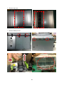
1
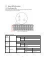
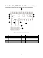
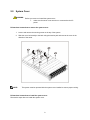
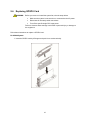
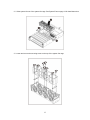
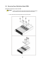
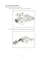
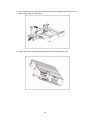
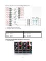
Dell PowerEdge C410x Hardware Owner’s Manual Notes, Cautions, and Warnings NOTE: A NOTE indicates important information that helps you make better use of your computer. CAUTION: A CAUTION indicates potential damage to hardware or loss of data if instructions are not followed. WARNING: A WARNING indicates a potential for property damage, personal injury, or death. Information in this publication is subject to change without notice. © 2010 Dell Inc. All rights reserved. Reproduction of these materials in any manner whatsoever without the written permission of Dell Inc. is strictly forbidden. Trademarks used in this text: Dell™, the DELL logo, and PowerEdge™ are trademarks of Dell Inc. Other trademarks and trade names may be used in this publication to refer to either the entities claiming the marks and names or their products. Dell Inc. disclaims any proprietary interest in trademarks and trade names other than its own. Regulatory Model B02S July 2010 Rev. A00 I Contents Notes, Cautions, and Warnings I Contents II Introduction 1 Checklist 1 Chapter 1: Product Overview 2 1.1 A Tour of the System 1.1.1 System Front View 1.1.2 System Back View 2 2 3 1.2 System LEDs Description 1.2.1. Front System LEDs 1.2.2. LAN LEDs 4 4 5 Chapter 2: Removing and Installing Hardware 6 Safety Measures 6 2.1. Dell PowerEdge C410X Middle Board Connectors and Jumpers 7 2.2. System Cover 8 2.3. GPGPU Cage 9 2.4. Replacing GPGPU Card 10 2.5. System Fans 14 2.6. System Fans Cages 16 2.7. Power Supplies 18 2.8. Removing Power Distribution Board (PDB) 19 2.9. Remove the power supply. See System Fans Cages 20 2.10. Replacing iPass Board 23 2.11. Replacing Middle Board 26 2.12. Replacing Front I/O Panel 27 2.13. Installing the Rail and the System 29 II Chapter 3: Cable Routings 31 iPass Port Mapping 32 Chapter 4: BMC Remote Management Console 33 Initial Configuration via DHCP Server Static/DHCP IP Controlled by Front Panel Button 33 34 Remote Management Console Overview 35 Enter Dell Remote Management Console Properties 36 36 Configuration Network Security User Services IPMI 37 37 38 39 40 41 Sessions 43 Updates 44 Utilities 45 Server Information Power Control Power Consumption GPU Power Consumption 46 46 47 48 Thermal Fans Temperatures 49 49 49 System Event Log Platform Events Traps Settings Email Settings 50 51 52 53 Chapter 5: Troubleshooting Your System 54 Chapter 6: Getting Help 59 Contacting Dell 59 Index 61 III Introduction Checklist Carefully unpack the Dell PowerEdge C410X server and check that the following items were included. One Dell PowerEdge C410X system Dell PowerEdge C410x Getting Started Guide Safety, Environmental, and Regulatory Information (SERI) Warranty and Support Information (WSI) or End User License Agreement (EULA) Contact Dell if some items are missing or appear damaged. 1 Chapter 1: Product Overview 1.1 A Tour of the System The following sections describe the external features of the Dell PowerEdge C410X server. 1.1.1 System Front View Figure 1 – Front View 1 System LED 8 GPGPU Cage 5 2 UID LED/Button 9 GPGPU Cage 6 3 Power LED/Button 10 GPGPU Cage 7 4 GPGPU Cage 1 11 GPGPU Cage 8 5 GPGPU Cage 2 12 GPGPU Cage 9 6 GPGPU Cage 3 13 GPGPU Cage 10 7 GPGPU Cage 4 2 1.1.2 System Back View Back view of system is shown below: Figure 2 – Back View 1 Power Module 1 11 iPass connector 6 2 Power Module 2 12 iPass connector 7 3 Power Module 3 13 iPass connector 8 4 Power Module 4 14 GPGPU Cage 11 5 BMC LAN Cable 15 GPGPU Cage 12 6 iPass connector 1 16 GPGPU Cage 13 7 iPass connector 2 17 GPGPU Cage 14 8 iPass connector 3 18 GPGPU Cage 15 9 iPass connector 4 19 GPGPU Cage 16 10 iPass connector 5 3 1.2 System LEDs Description 1.2.1. Front System LEDs The front system LEDs contain Status LED, Power LED and UID LED information. The detailed LEDs information is listed below: Figure 3 –Front System LEDs Table 1 Front System LEDs Status LED UID LED Displays status/errors and is controlled by BMC. Color Condition Occurrence Amber Blink Fast Power supply fail On FAN fail or sensor error Blink GPU card fail Lights when front or rear ID button is pressed. Color Condition Occurrence Blue Off No identification Blinking ID Button pressed on system (ID command executed) Lights green when server is powered on. Color Power LED Green 4 Condition Occurrence On Power on Blinking Power on fail or without any GPU card 1.2.2. LAN LEDs Figure 4 – LAN LEDs Table 2 LAN LEDs LAN LAN Link/Activity Color Condition Occurrence Green On LAN Link / no Access Blink LAN Access N/A Off Idle 10 LAN Speed N/A Off 10Mbps connection 100 LAN Speed Green On 10Mbps connection Blink Port identification with 10 or 100Mbps connection GbE LAN Speed Yellow On 1Gbps connection Blink Port identification with 1Gbps connection 5 Chapter 2: Removing and Installing Hardware Safety Measures Computer components and electronic circuit boards can be damaged by discharges of static electricity. Working on computers that are still connected to a power supply can be extremely dangerous. Follow the simple guidelines below to avoid damage to your computer or injury to yourself. Always disconnect the computer from the power outlet whenever you are working inside the computer case. If possible, wear a grounded wrist strap when you are working inside the computer case. Alternatively, discharge any static electricity by touching the bare metal system of the computer case, or the bare metal body of any other grounded appliance. Hold electronic circuit boards by the edges only. Do not touch the components on the board unless it is necessary to do so. Do not flex or stress the circuit board. Leave all components inside the static-proof packaging until you are ready to use the component for the installation. 6 2.1. Dell PowerEdge C410X Middle Board Connectors and Jumpers Figure 4 displays the most important DELL PowerEdge C410X middle board components. Figure 4 –Middle Board Connectors and Jumpers Item Component Items Component 1. PCI-E connectors 6. Front I/O connector 2. PCI-E connectors 7. FAN connectors 3. Power connectors 8. FAN LED connectors 4. iPass connectors 9. Failover setting pin header 5. Battery 7 2.2. System Cover WARNING: Before you remove or install the system cover: make sure the server is not turned on or connected to the AC power. Follow these instructions to remove the system cover: 1. Loosen and remove the securing screw on the top of the system. 2. Slide the cover horizontally to the back using the traction pad and remove the cover in the direction of the arrow. NOTE: This system must be operated with the system cover installed to ensure proper cooling. Follow these instructions to install the system cover: Reverse the steps above to install the system cover. 8 2.3. GPGPU Cage NOTE: When you remove or install the GPGPU cage, note the following points: Take note of the drive tray orientation before sliding it out. The tray will not fit back into the bay if inserted incorrectly. Follow these instructions to remove the cage: 1. Press the release button along the direction of the arrow. 2. Slide the cage assembly out of the system. Follow these instructions to install the cage: Reverse the steps above to install the cage. 9 2.4. Replacing GPGPU Card WARNING: Before you remove or install the system fan, take the steps below: Make sure the system is not turned on or connected to the AC power. Disconnect all necessary cable connections. Turn off the specific single GPU cage power. Failure to observe these warnings could result in personal injury or damage to the equipment. Follow these instructions to replace a GPGPU card: For M1060 System 1. Insert the GPGPU card by 45 degree and push it into socket vertically. 10 2. Secure the card in place with screws and place the GPGPU side cover as illustration arrow show. 3. Secure the GPGPU side cover and back cover in place with screws. 11 Follow these instructions to replace a GPGPU card: For M2050 System 1. Attach the support bracket on the GPGPU board and secure it in place with screws. 2. Insert the GPGPU card by 45 degree and push it into socket vertically. 12 3. Secure the card in place with screws and place the GPGPU side cover as illustration arrow show. 4. Secure the card in place with screws and place the GPGPU side cover as illustration arrow show. 13 2.5. System Fans In case a of system fan failure, you can quickly replace the system fan. WARNING: Before you remove or install the system fan, take the steps below: Make sure the system is not turned on or connected to the AC power. Disconnect all necessary cable connections. Failure to observe these warnings could result in personal injury or damage to the equipment. Follow the instruction to remove the system fan: 1. Loosen and remove the securing screw on the top of the system. 14 2. Lift the system fan out of the system fan cage. Follow these instructions to install the system fan: Reverse the step above to install the system fan. 15 2.6. System Fans Cages WARNING: Before you remove or install the system fan cage, take the steps below: Make sure the system is not turned on or connected to the AC power. Disconnect all necessary cable connections. Failure to observe these warnings could result in personal injury or damage to the equipment. 1. Loosen and remove the securing screw on the top of the system. 16 2. Lift the system fan out of the system fan cage. See System Fans on page 14 for detail instruction. 3. Loosen and remove the securing screw on the top of the system fan cage. 17 2.7. Power Supplies In case of a power supply failure, you can quickly replace the power supply unit. Follow these instructions to remove the power supply: WARNING: In order to reduce the risk of injury from electric shock, disconnect the failed power supply from the AC power before removing it from the system. 1. Pull up the power supply handle. 2. Press the retaining clip on the right side of the power supply along the direction of the arrow. 3. At the same time, pull out the power supply by using its handle. NOTE: The power supply takes considerable force to remove. Follow these instructions to install the power supply: Insert the replacement power supply firmly into the bay. The retaining clip should snap. Connect the AC power cord to the replacement power supply. 18 2.8. Removing Power Distribution Board (PDB) Follow these instructions to remove the PDB: WARNING: In order to reduce the risk of injury from electric shock, disconnect the failed power supply from the AC power before removing it from the system. 1. Loosen and remove the securing screws on the top of the system. 18 2.9. Remove the power supply. See System Fans Cages WARNING: Before you remove or install the system fan cage, take the steps below: Make sure the system is not turned on or connected to the AC power. Disconnect all necessary cable connections. Failure to observe these warnings could result in personal injury or damage to the equipment. 4. Loosen and remove the securing screw on the top of the system. 18 5. Lift the system fan out of the system fan cage. See System Fans on page 14 for detail instruction. 6. Loosen and remove the securing screw on the top of the system fan cage. 18 2. Power Supplies on page 18. 3. Loosen and remove the securing screws on the top of power supply cage and remove the securing screw on the side of the system. 4. Loosen and remove the securing screws on the PDB. 22 2.10. Replacing iPass Board Follow these instructions to replace the iPass board: 1. Loosen and remove the securing screws on the top of the system. 2. Remove the power supply. See Power Supplies on page 18 for detail instruction. 23 3. Loosen and remove the securing screws on the top of power supply cage and remove the power supply cage out of the system. 4. Loosen and remove the securing screws on the top of iPass connector cage. 24 5. Remove iPass connector cage. 6. Loosen and remove the securing screws on the top of iPass board. 25 2.11. Replacing Middle Board Follow these instructions to replace the middle board: 1. Remove the system cover. See System Cover on page 8. 2. Remove the fourteen (14) screws securing the mainboard in place. Lift the middle board out of the system in the direction of the arrow, front edge first, to clear the I/O ports. 26 2.12. Replacing Front I/O Panel WARNING: Before you remove or install the system cover: make sure the system is not turned on or connected to the AC power. 1. Loosen and remove the securing screws as illustration shown below 2. Loosen the securing screws and remove the ear board cover. 27 3. Loosen and remove the securing screws on the ear board. 28 2.13. Installing the Rail and the System WARNING: Before you remove or install the system cover: make sure the system is not turned on or connected to the AC power. Follow these instructions to install the rail into a rack: 1. Install the sliding rails into the rack. 2. Align the inner rails with the sliding rails of the rack. 29 3. Push the system into the sliding rails until the locking latch clicks into place. 4. Connect ipass connectors and power connectors. 30 Chapter 3: Cable Routings 1 Fan Power Cable 2 Front I/O Cable 3 RJ45 Cable 4 Fan LED Cable 5 GPU Cable 6 Switch Cable 31 iPass Port Mapping IPASS Mapping 1 Mapping 2 Mapping 3 Mapping 4 1 5 2 6 3 7 4 8 VS VS VS VS GPGPU IPASS 1, 15 1 2, 16 5 3, 13 2 4, 14 6 5, 11 3 6, 12 7 7, 9 4 8, 10 8 32 GPGPU VS VS VS VS 1,2 , 15, 16 N/A 3,4, 13, 14 N/A 5,6 , 11, 12 N/A 7,8 , 9, 10 N/A Chapter 4: BMC Remote Management Console This chapter provides information on the various functions of the Dell Remote Management Console GUI’s (Graphics User Interface). Initial Configuration via DHCP Server Before entering the Dell Remote Management Console, you need to connect the DHCP server in the subnet to which it is physically connected. If a DHCP server is found, it may provide a valid IP address, gateway address and net mask. Before you connect the device to your local subnet, be sure to complete the corresponding configuration of your DHCP server. It is recommended to configure a fixed IP assignment to the MAC address of the system. 33 Static/DHCP IP Controlled by Front Panel Button The following illustration shows the instruction for gathering IP source using front panel button. Start Function Locked ID button press IP source = DHCP N Sleep 1sec N Y N ID press count + 1 Y Y Change IP source to static Change IP source to DHCP N Power button press Static IP = 0.0.0.0 Y Y Power press count + 1 Set IP = 192.168.0.120 and subnet = 255.255.255.0 N N ID LED solid 5sec ID LED blinking fast 5sec (ID press time >= power time) and Power time >= 4sec and function unlock N Power button released Wait 30sec to finish Function Unlock Clear ID press count and power press count Y 34 Remote Management Console Overview 1. 2. 3. Open a web browser and type in your identified IP. The IP address can be found using your DHCP server. A dialog box prompts you to enter Username and Password. Enter the following values: Username: root Password: root NOTE: The default user name and password are in lower-case characters. NOTE: When you log in using the root user name and password, you have full administrative privileges. It is advised that once you log in, you should change the root password. 35 Enter Dell Remote Management Console After you successfully log into your Dell Remote Management Console, the Remote Management Console GUI appears. Properties Properties displays the firmware version of current remote client system. 36 Configuration Network You can view and modify the network settings on this screen. Select whether to obtain an IP address automatically or configure one manually. It is recommended to use DHCP if your environment has a DHCP server. You can set DHCP (obtain the IP address automatically) or STATIC IP (configure the IP address manually). When you finish configuration, click Apply Changes or for re-configuration click Refresh. 37 Security Security shows the current certificate status. To generate a new certificate, click Generate Certificate . To upload a certificate, click Upload Certificate. 38 User To configure a specific user, click the User ID. To display new user information, click Refresh. 39 Services You can configure the web server parameters (such as, HTTP Port Number, HTTPS Port Number, and Timeout) on a remote computer. By default, the timeout is 5 for the Max Sessions and 1 for the Active Sessions. When you finish the configuration, click Apply Changes. 40 IPMI This screen contains two sections: IPMI Serial and IPMI Settings. IPMI Serial There are three serial configuration in IPMI Serial: Connection Mode Settings, Baud Rate, and Channel Privilege Level Limit. The Connection Mode Settings allows user to select the Console redirection type and to manage the system from a remote location. Once the connection mode is set, select the Baud Rate from the drop-down list. With Channel Privilege Level Limit, users can be configured to operate with a particular maximum Privilege Level. Privilege levels tell the BMC which commands are allowed to be executed. Table 3 lists the currently defined User Privilege Levels. Table 3 User Privilege Levels User This may be considered the lowest privilege level. Operator All BMC commands are allowed, except for configuration commands that can change the behavior of the out-of-band interfaces. For example, Operator privilege does not allow the capability to disable individual channels, or change user access privileges. Administrator All BMC commands are allowed, including configuration commands. An Administrator can even execute configuration commands that would disable the channel that the Administrator is communicating over. 41 IPMI Settings IPMI Settings provides remote configuration over LAN. To activate IPMI remote configuration by LAN, check Enable IPMI Over LAN option, define the Channel Privilege Level Limit, and enter the Encryption Key. When you finish the configuration, click Apply Changes. 42 Sessions This screen displays information on Active Sessions. Additionally, the trash can icon provides the delete function for privileged users. Click Refresh to refresh the Sessions status. 43 Updates The firmware can be updated remotely. To update firmware, follow the instruction below: 1. Select the file on your local system using Browse. 2. Click Update to delete the current version and update to the new version. 44 Utilities Utilities provides System reboot and Factory default restore functions. To reboot system, click Reboot. To restore factory default, click Factory Default. 45 Server Information Power Control The Power Control allows you to power on/off/cycle the remote host system. Additionally you can see the remote power status. To perform the power control operation, select the operation and click Apply Changes. 46 Power Consumption This screen displays information on the system power consumption. The information includes Current Power Consumption, Power Consumption Monitoring Start Date, Max/Min Power Consumption, and Average Power Consumption. 47 GPU Power Consumption This screen displays the status of GPU power consumption. Each sensor displays different color to indicate the health status of a specified GPU device. The green color indicates the device is healthy and there’s no sensor that has any alert. The yellow color indicates the device has at least one sensor that has warning alert. The red color indicates the device has at least one sensor that has a critical alert. 48 Thermal This screen displays the Fans and Temperatures sensors of a remote host system. Click Refresh to update current health status for both Fans and Temperatures. The green color indicates the device is healthy and there’s no sensor that has any alert. The yellow color indicates the device has at least one sensor that has a warning alert. The red color indicates the device has at least one sensor that has a critical alert. Fans Temperatures 49 System Event Log System Event Log: It records the event when sensor has an abnormal state. When the log matches the pre-defined alert, the system sends out the notification automatically, if it is pre-configured. 50 Platform Events A platform event filter (PEF) can trigger an action and generate an alert when a critical hardware-related event occurs. For each PEF, you can choose the action to be taken when a platform event occurs. You can also choose to generate and send an alert when a platform event occurs. In the Platform Events screen, you can enable the generation of platform event alerts globally by clicking Global Alerting Enable. When you finish the configuration, click Apply Changes. 51 Traps Settings In the Trap Settings, user can set the IPv4 and Ipv6 Destination List. IPv6 and IPv4 are two completely separate protocols. IPv6 is not backwards compatible with IPv4, and IPv4 hosts and routers will not be able to deal directly with IPv6 traffic. IPv6 has a significantly larger address space than IPv4. This results from the use of a 128-bit address, whereas IPv4 uses only 32 bits. When you finish the configuration, click Apply Changes. 52 Email Settings If you want the alert to be sent by email, you can configure to specify the e-mail address, subject and message in the Email Settings. After you finish the configuration, click Apply Change to save the settings. 53 Chapter 5: Troubleshooting Your System Safety First—For You and Your System WARNING: Whenever you need to lift the system, get others to assist you. To avoid injury, do not attempt to lift the system by yourself. WARNING: Before removing the system cover, disconnect all power, then unplug the AC power cord, and then disconnect all peripherals, and all LAN lines. CAUTION: Many repairs may only be done by a certified service technician. You should only perform troubleshooting and simple repairs as authorized in your product documentation, or as directed by the online or telephone service and support team. Damage due to servicing that is not authorized by Dell is not covered by your warranty. Read and follow the safety instructions that came with the product. Symptom: iPass card / port not recognized by the system Check System Status (System must stay switched off) 1. Plug-in all four power cords to the 220V A/C power supply. NOTE: Do not press power button on the system. 2. Check front panel LED (ID and Power LED) ID and Power LED should not light at the beginning. After 30 seconds or so, when BMC is ready, ID LED and Power LED blink once. 3. System powers on. After 40 seconds, power LED lights. 54 4. When GPU cards are ready, power on the system for test. 5. All GPU cards LED should lights. If not, see Checking GPU Card on page 42. Checking GPU Card 1. Power off and remove top cover. 2. Power on and check if GPU card LED lights. 55 3. If not, power off, then reinstall GPU card again or swap GPU card. 4. If not, see Check iPass cable. Checking iPass Cable 1. Check if iPass cable is properly connected. 2. If not, power off the system and plug-in power cable again. 3. If not, swap iPass cable. 56 Checking iPass Connector to PowerEdge C6100 Systems 1. Check BTB Connectors to iPass Board. 2. Check System SMBUs device routing table. IPASS TOP IPASS Bottom iPass 1: Slot 1/15 iPass 5: Slot 2/16 iPass 2: Slot 3/13 iPass 6: Slot 4/14 iPass 3: Slot 5/11 iPass 7: Slot 6/12 iPass 4: Slot 7/9 iPass 8: Slot 8/10 Check if iPass Board (GS-IPASS2 / GS-IPASS3) is installed properly 1. Power off the system. 57 2. Remove top cover. 3. Remove PSU top cover. Press 58 4. Remove power cage. 5. Press iPass board to ensure it contacts middle plane. 6. Restart system and test it again. Chapter 6: Getting Help Contacting Dell For customers in the United States, call 800-WWW-DELL (800-999-3355). NOTE: If you do not have an active Internet connection, you can find contact information on your purchase invoice, packing slip, bill, or Dell product catalog. Dell provides several online and telephone-based support and service options. Availability varies by country and product, and some services may not be available in your area. To contact Dell for sales, technical support, or customer service issues: 1. Visit support.dell.com. 2. Click your country/region at the bottom of the page. For a full listing of country/region click All. 3. Click All Support from Support menu. 4. Select the appropriate service or support link based on your need. 59 5. Choose the method of contacting Dell that is convenient for you. 60 Index back view, 3 iPass port mapping, 34 cable routings, 33 LAN LEDs, 5 checking GPU card, 57 middle board checking iPass cable, 58 replacing, 27 checking iPass connector, 59 middle board connectors and jumpers, 7 checklist, 1 platform events, 53 configuring power consumption, 49 IPMI, 43 power distribution board network, 39 removing, 19 security, 40 power supplies, 18 services, 42 rail and system sessions, 45 installing, 30 user, 41 remote management console email settings, 55 overview, 37 firmware safety measures, 6 updates, 46 server information power control, 48 front I/O panel replacing, 28 system cover, 8 front view, 2 system event log, 52 getting help system fans, 14 contacting Dell, 62 system fans cages, 16, 20 GPGPU cage, 9 system LEDs GPU power consumption, 50 front, 4 initial configuration via DHCP server, 35 traps settings, 54 iPass board troubleshooting your system, 56 utilities, 47 replacing, 24 61