1
LBI-39171
Installation Manual
EDACS NETWORK
MANAGEMENT
ericssonz
LBI-39171
NOTICE!
This manual covers Ericsson and General Electric products manufactured and sold by Ericsson Inc.
NOTICE!
This product may only be used for the functions described in this manual. Use of the product for other purposes shall
constitute a violation of the license. Moreover, any addition of non-Ericsson approved hardware and software may cause the
product to malfunction.
NOTICE!
The software contained in this device is copyrighted by Ericsson Inc. Unpublished rights are reserved under the copyright
laws of the United States.
This manual is published by Ericsson Inc., without any warranty. Improvements and changes to this manual necessitated by
typographical errors, inaccuracies of current information, or improvements to programs and/or equipment, may be made by
Ericsson Inc., at any time and without notice. Such changes will be incorporated into new editions of this manual. No part
of this manual may be reproduced or transmitted in any form or by any means, electronic or mechanical, including
photocopying and recording, for any purpose, without the express written permission of Ericsson Inc.
EDACS and MASTR are registered trademarks, and GETC, Failsoft, Aegis, C3, C3 Maestro and Guardog are trademarks of
Ericsson Inc.
Unix is the registered trademark of UNIX Systems Laboratories in the U.S.A. and other countries.
TSSterm is the trademark of Thursby Software System, Inc.
Hewlett-Packard and HP are registered trademarks of Hewlett-Packard Company.
Digital, DEC, DECnet, DECwindows, VT, VT420, and VMS are trademarks of Digital Equipment Corporation.
iFOR
is a trademark and Gradient is a registered trademark of Gradient Technologies, Inc.
The Graphics Interchange Format is the Copyright property and GIFSM is the Service Mark property of Compuserve
Incorporated.
OSF/Motif is a trademark of the Open Software Foundation.
MultiNet and MultiWare are registered trademarks of TGV, Inc.
Copyright November 1996, Ericsson, Inc.
2
LBI-39171
TABLE OF CONTENTS
Section/Paragraph
Page
1. PREFACE.............................................................................................................................................................9
1.1 MANUAL ORGANIZATION ......................................................................................................................9
2. INTRODUCTION..............................................................................................................................................10
2.1 HOW TO USE THIS MANUAL................................................................................................................10
2.2 CONVENTIONS USED IN THIS MANUAL ...........................................................................................10
3. DOCUMENTATION.........................................................................................................................................11
3.1 HEWLETT-PACKARD DOCUMENTATION..........................................................................................11
3.2 RELATED ERICSSON PUBLICATIONS.................................................................................................11
4. SITE PREPARATION ......................................................................................................................................13
4.1 EQUIPMENT LOCATION ........................................................................................................................13
4.2 EQUIPMENT ROOM GROUNDING .......................................................................................................14
4.3 OPERATING ENVIRONMENT................................................................................................................14
4.4 ELECTRICAL POWER .............................................................................................................................14
5. HARDWARE INSTALLATION ......................................................................................................................15
5.1 UNPACKING EQUIPMENT .....................................................................................................................15
5.2 NM0 CONFIGURATION ..........................................................................................................................16
5.2.1 Basic NM0 Configuration Hardware ................................................................................................16
5.2.2 NM0 Upgrade Options......................................................................................................................16
5.2.3 Rear Panel Connectors......................................................................................................................17
5.2.4 NM0 System Cabling........................................................................................................................18
5.3 NM1 CONFIGURATION ..........................................................................................................................19
5.3.1 Basic NM1 Configuration Hardware ................................................................................................19
5.3.2 NM1 Upgrade Options......................................................................................................................19
5.3.3 NM1 System Cabling........................................................................................................................19
5.4 NM2 CONFIGURATION ..........................................................................................................................21
5.4.1 Basic NM2 Configuration Hardware ................................................................................................22
5.4.2 NM2 Upgrade Options......................................................................................................................22
5.4.3 NM2 System Cabling........................................................................................................................22
5.5 REMOTE X-STATIONS............................................................................................................................23
5.5.1 HP “X” Station Hardware.................................................................................................................23
5.5.2 X-Station Cabling .............................................................................................................................24
6. INITIAL SOFTWARE INSTALLATION .......................................................................................................25
6.1 STEP 1 -LOAD THE HP ENWARE X-STATION SOFTWARE (NM1 AND NM2 HP SERVERS
ONLY) ..............................................................................................................................................................25
3
LBI-39171
TABLE OF CONTENTS
Section/Paragraph
Page
6.2 STEP 2 - SETUP X-STATION TERMINAL (NM1 AND NM2 HP SERVER ONLY) ............................26
6.3 STEP 3 - INSTALL OPENVIEW NETWORK NODE MANAGER(NM0, NM1 AND NM2).................26
6.4 STEP 4 - INSTALL EDACS NETWORK MANAGER APPLICATION..................................................28
6.5 STEP 5 - INSTALL LICENSING RUN TIME KIT...................................................................................28
6.6 STEP 6 - RELOCATE EDACS FILES.......................................................................................................31
6.7 STEP 7 - INSTALL TSSTERM SOFTWARE ...........................................................................................32
6.8 STEP 8 - CONFIGURE X-STATION (IF PRESENT) TO USE TSSTERM .............................................33
6.9 STEP 9 - INSTALL TSSTERM LICENSE ................................................................................................34
6.10 STEP 10 - CONFIGURE NETWORK MANAGER STATION FONT SERVER ...................................34
6.11 STEP 11 - INSTALL PC-XWARE HOST SOFTWARE (XREMOTE) ..................................................36
6.11.1 HP Workstation Configuration........................................................................................................36
6.11.2 HP Server Configuration (NM1 and NM2).....................................................................................38
6.12 STEP 12 - INSTALL CEC/IMC MANAGER HP-UX CLIENT SOFTWARE........................................39
6.13 STEP 13 - PERFORM FULL SYSTEM IMAGE BACKUP ....................................................................39
6.14 STEP 14 - COMPLETING THE SOFTWARE INSTALLATION PROCESS ........................................40
7. CUSTOMIZING THE NETWORK MANAGER SOFTWARE....................................................................41
7.1 STEP 1 - CREATE USER ACCOUNTS ....................................................................................................41
7.2 STEP 2 - SETUP USER ACCOUNT PROFILE ........................................................................................42
7.2.1 C SHELL User Environment.............................................................................................................42
7.2.2 KORN Shell User Environment ........................................................................................................43
7.3 STEP 3 - SETUP USER ACCOUNT LOGIN ENVIRONMENT ..............................................................43
7.3.1 Setting Up The VUE Format Panel Icon...........................................................................................43
7.3.2 Set Up Home Session........................................................................................................................45
7.3.3 User Setup for PC-Xware..................................................................................................................45
7.3.4 Complete User Setup.........................................................................................................................46
7.4 STEP 4 -SET UP VUE EXIT CONDITION ..............................................................................................46
7.5 STEP 5 - SETUP HOST NAME TABLE ...................................................................................................46
7.6 STEP 6 - CUSTOMIZING HP OPENVIEW NETWORK NODE MANAGER ........................................47
7.6.1 Community Names............................................................................................................................48
7.6.2 Fault Propagation ..............................................................................................................................48
7.6.3 Disable IP Map Polling .....................................................................................................................48
7.6.4 Event Configuration ..........................................................................................................................48
7.7 STEP 7 - MAP GENERATION..................................................................................................................49
7.7.1 Configuration Rules ..........................................................................................................................49
7.7.2 Generate EDACS Maps ....................................................................................................................51
7.8 STEP 8 - ASSIGN THE OPENVIEW REDUCED MENU SET................................................................53
7.9 STEP 9 - ASSIGN THE EDACS REDUCED MENU SET........................................................................54
4
LBI-39171
TABLE OF CONTENTS
Section/Paragraph
Page
7.10 STEP 10 - RESTRICT ACCESS TO OPENVIEW NETWORK NODE MANAGER ............................55
7.11 STEP 11 - CONFIGURE PRINTERS ......................................................................................................56
7.12 STEP 12 - PERFORM FULL SYSTEM IMAGE BACKUP....................................................................56
8. ON-SITE CONFIGURATION..........................................................................................................................58
8.1 CEC/IMC MANAGER FOR NT SETUP...................................................................................................58
8.2 JESSICA PI SETUP ...................................................................................................................................59
8.3 BCU/CAL SETUP ......................................................................................................................................60
8.4 EDG SETUP ...............................................................................................................................................61
8.5 SYSTEM MANAGER SETUP ..................................................................................................................61
8.5.1 Software Installation And Configuration ..........................................................................................61
8.5.2 Post-Installation Tasks:.....................................................................................................................63
8.6 POLLING SETUP ......................................................................................................................................65
8.6.1 Device Polling Interval .....................................................................................................................65
8.6.2 Clock Synchronization Node ............................................................................................................66
8.6.3 Clock Polling Interval .......................................................................................................................66
8.6.4 Setup .................................................................................................................................................66
8.7 UPGRADING EDACS NETWORK MANAGER APPLICATION SOFTWARE ....................................67
8.8 PROCEDURE TO OBTAIN MAC ADDRESSES.....................................................................................68
8.8.1 System Manager................................................................................................................................68
8.8.2 PI/BCU/CAL/EDG ...........................................................................................................................68
8.8.3 CAL Terminal Server .......................................................................................................................68
8.8.4 CEC/IMC Manager for NT...............................................................................................................68
8.8.5 Network Manager .............................................................................................................................68
9. OPTIONAL ON-SITE CUSTOMIZATION....................................................................................................69
9.1 CUSTOMIZE MSM/SM SITE/DEVICE LABELS....................................................................................69
9.2 CUSTOMIZE EVENT DESCRIPTION.....................................................................................................70
9.2.1 Modifying Event Descriptions ..........................................................................................................70
9.3 CUSTOMIZING BACKGROUND GEOGRAPHICAL MAPS.................................................................70
9.4 JESSICA PI OR BCU/CAL ALARM THRESHOLD MIBS (EDACS-102 MIB) .....................................71
9.4.1 Setting the Alarm Thresholds............................................................................................................71
9.4.2 Deleting the Alarm Thresholds .........................................................................................................72
9.5 ICON MODIFICATIONS ..........................................................................................................................72
10. LICENSE UTILITIES AND OPERATIONS ................................................................................................73
10.1 MONITORING LICENSE STATUS .......................................................................................................73
10.2 INSTALLING THE LICENSE PASSWORD ..........................................................................................73
10.3 DELETING THE LICENSE PASSWORD ..............................................................................................73
5
LBI-39171
TABLE OF CONTENTS
Section/Paragraph
Page
10.4 RETRIEVING THE LICENSE TARGET ID...........................................................................................74
10.5 IFOR/LS LICENSE MAINTENANCE PROCEDURE ............................................................................74
10.5.1 Restoring License............................................................................................................................74
10.5.2 Using IFOR/LS In Multiple Systems ..............................................................................................74
11. SYSTEM MAINTENANCE ............................................................................................................................79
11.1 FILE CLEAN-UP......................................................................................................................................79
11.2 SETTING UP AUTOMATIC SNAPSHOTS ...........................................................................................79
11.3 REMOVING OLD SNAPSHOTS ............................................................................................................80
11.4 BACKING UP HP OPENVIEW LOGS ...................................................................................................80
11.5 RESTORING HP OPENVIEW FROM A BACKUP ...............................................................................81
11.6 CLEANING TAPE DRIVE HEADS ........................................................................................................82
11.7 PRINTER SETUP AND CONFIGURATION..........................................................................................82
11.7.1 Local Printer Configuration: ...........................................................................................................82
11.7.2 Remote Printer Configuration: ........................................................................................................83
11.7.3 Network Printer Configuration:.......................................................................................................84
11.8 CHANGING NETWORK MANAGER IP ADDRESS ............................................................................85
12. REMOTE ACCESS .........................................................................................................................................86
12.1 OVERVIEW .............................................................................................................................................86
12.1.1 Modem-HP Workstation Serial Port Connection ............................................................................86
12.1.2 Modem-HP Server Support Link Modem Port Connection ............................................................87
12.1.3 Modem-LAN Terminal Server Connection.....................................................................................87
12.2 CONFIGURATION ..................................................................................................................................88
12.2.1 PC Configuration - VT100 Emulation ............................................................................................88
12.2.2 Modem Configuration .....................................................................................................................89
12.2.3 PC Configuration for X Terminal Emulation ..................................................................................91
12.3 REMOTE ACCESS OPERATIONAL TESTS.........................................................................................93
12.3.1 VT100 Standard Login Test............................................................................................................93
12.3.2 X Windows Application Test..........................................................................................................94
12.4 SUPPLEMENTAL MODEM INFORMATION.......................................................................................96
12.4.1 Modem AT Command Descriptions ...............................................................................................96
12.4.2 Modem Register Descriptions .........................................................................................................96
12.4.3 HP-800 Series Modem Cable Pinout ..............................................................................................97
12.4.4 Hayes Accura 28.8 Modem Configuration......................................................................................97
12.4.5 HP-9000/800 Series Modem Setup .................................................................................................98
13. APPENDIX A - OPENVIEW COMMANDS...............................................................................................102
13.1 MAP PERMISSIONS - OVWPERMS COMMAND .............................................................................102
14. APPENDIX B - UNIX COMMANDS...........................................................................................................104
6
LBI-39171
TABLE OF CONTENTS
Section/Paragraph
Page
15. APPENDIX C - CONNECTOR DIAGRAMS .............................................................................................107
16. APPENDIX D - EDACS LICENSE REGISTRATION FAX FORM ........................................................110
17. INDEX.............................................................................................................................................................111
LIST OF FIGURES
Figure
Title
Page
Figure 1 - HP 9000 - 700 Series Workstation Rear Panel Connectors.....................................................................17
Figure 2 - 712/60 Interconnect Diagram ..................................................................................................................18
Figure 3 - HP 9000 - 800 Series Model G, Business Server Rear Panel Connectors...............................................20
Figure 4 - HP 9000/800, Model G, Business Server Interconnect Diagram.............................................................21
Figure 5 - ENVIZEX X-Station Rear Panel Connectors ..........................................................................................23
Figure 6 - 712/60 Interconnect Diagram ..................................................................................................................24
Figure 7 - Add A User Account Dialog Box ............................................................................................................41
Figure 8 - OpenView Front Panel ............................................................................................................................45
Figure 9 - Style Manager Startup Panel ...................................................................................................................45
Figure 10 - OpenView Window ...............................................................................................................................47
Figure 11 - Modem to HP Workstation Installation .................................................................................................86
Figure 12 - Modem to HP Server Installation ..........................................................................................................87
Figure 13 - Modem to LAN Terminal Server Installation........................................................................................87
Figure 14 - 9000/800 Series Modem Cable (40233A) .............................................................................................97
7
LBI-39171
LIST OF TABLES
Figure
Title
Page
Table 1 - Basic NM0 Configuration Hardware ........................................................................................................16
Table 2 - NM0 Hardware Upgrade Options .............................................................................................................16
Table 3 - Basic NM1 Configuration Hardware ........................................................................................................19
Table 4 - NM1 Hardware Upgrade Options .............................................................................................................19
Table 5 - Basic NM1 Configuration Hardware ........................................................................................................22
Table 6 - NM1 Hardware Upgrade Options .............................................................................................................22
Table 7 - HP “X” Station Hardware .........................................................................................................................23
Table 8 - Graphics and LAN AUI Connector Pinout .............................................................................................107
Table 9 - RS-232 Connector Pinout .......................................................................................................................107
Table 10 - SCSI Connector Pinout .........................................................................................................................108
Table 11 - PS2 Connector Pinout ...........................................................................................................................109
Table 12 - Parallel Connector Pinout .....................................................................................................................109
8
PREFACE
LBI-39171
1. PREFACE
This is one of four manuals for the EDACS Network Manager. This manual provides instructions for installing and
configuring the Network Manager station and associated equipment.
Additional documentation for the Network Manager is available in the following publications:
•
•
•
EDACS Network Management System Manual (LBI-39215):
This manual provides a system level overview of Network Management.
EDACS Network Management Enterprise Management Information Base (MIB) Reference Manual (LBI-39170):
This manual contains the EDACS common MIB files and defines each item identified within the file groups.
EDACS Network Manager User’s Guide (LBI-39169):
This manual contains information for using the Network Management system.
1.1 MANUAL ORGANIZATION
The manual is divided into the following sections:
Section 1
Preface - The preface section identifies the other manuals in the Network Manager manual set and
introduces the reader to the organization of this manual.
Section 2
Introduction - The Introduction section explains how to use this manual and annotation
conventions used in this manual.
Section 3
Documentation - This section provides a list of Ericsson documents for the associated EDACS
elements which might interface with the Network Manager. It also provides a list of manual and
documents which may be obtained (or are provided) by vendors and outside sources.
Section 4
Network Manager Installation - This section provides an overview of the installation process.
Section 5
Site Preparation - This section describes some of the issues concerning the physical site where
the Network Manager equipment will be located..
Section 6
Hardware Installation - This section provides instructions for unpacking and interconnecting the
Network Manager hardware.
Section 7
Initial Software Installation - This section provides the sequence of steps required to initially
install the software.
Section 8
Customizing The Network Manager Software - This section provides step-by-step instructions
for setting up the Network Manager software to meet a customer’s specific needs.
Section 9
On-Site Configuration - This section provides instructions for configuring other network
elements, including the System Manager, Jessica, BCU/CAL, EDG, and IMC for operating with
the Network Manager.
Section 9
Optional On-Site Customization - This section provides instructions for performing on-site
customizing of the Network Manager to meet the customer’s specific requirements.
Section 11
License Utilities and Operations - This section provides procedures for installing, upgrading and
monitoring the various licenses.
Section 12
System Maintenance - This section contains instructions for performing recurring system
maintenance tasks.
Section 13
Remote Access - This section provides background information and additional configuration
information for using modems to remotely access to the Network Manager.
9
LBI-39171
INTRODUCTION
2. INTRODUCTION
This manual contains installation instructions, physical and functional descriptions, specifications, and initial setup
instructions for the Enhanced Digital Access Communications System (EDACS ) Network Manager. The manual serves a
guide for persons responsible for installing, maintaining, or performing administrative tasks. It assumes these individuals are
familiar with the operating procedures for the various support software applications and the Network Management application
software.
2.1 HOW TO USE THIS MANUAL
This manual describes the tasks associated with planning a Network Management system, installing the system,
configuring the system to the customers needs, and maintaining the system at the Administrator level.
To locate a specific task refer to the Table of Contents or the Index.
2.2 CONVENTIONS USED IN THIS MANUAL
This manual uses the following typographic conventions:
Boldface Courier Font
Used to denote UNIX commands entered via the keyboard. These commands are
case sensitive and must include all spaces and periods.
Courier Text
Normal text in the courier font represents text displayed
Boldface Italics
Used to denote file names and paths when identified in the text.
Italics
Manual Titles, emphasized words, and UNIX command parameters supplied by the
user.
For example, an term IP Address would be replaced by a specific address such as
192.168.201.0.
<ENTER>
This indicates pressing the RETURN or ENTER key to activate a command.
“Double Quotes”
Indicates titles of sections, within a manual, SAM windows, and SAM menu bar
menus
->
Denotes stepping from one menu bar item to a submenu item, such as File -> Exit.
10
DOCUMENTATION
LBI-39171
3. DOCUMENTATION
In may be necessary to consult one or more of the following documents when installing or maintaining the Network
Management system. These manuals will also provide additional guidance if you encounter technical difficulties during the
installation or configuration process.
3.1 HEWLETT-PACKARD DOCUMENTATION
The following Hewlett-Packard (HP) manuals provide additional information on the HP products used with the Network
Manager:
•
HP 9000 Series Owner’s Guide
•
B1171-90079
HP Visual User Environment User’s Guide
•
J2316-90001
HP OpenView Network Node Manager User’s Guide
•
J2316-90000
HP OpenView Windows User’s Guide
•
J2310-90002
HP OpenView Windows Application Design and Style Guide
•
J2311-90001
HP OpenView SNMP Programmer’s Guide and Reference
•
J2311-90004
HP OpenView SNMP Management Platform Performance and Configuration Guide with HP
Network Node Manager Examples for Release 3.3
•
J2319-90002
HP OpenView Programmer’s Guide
•
J2319-90009
HP OpenView Programmer’s Reference
•
B2355-90037
HP Remote Access Manual
3.2 RELATED ERICSSON PUBLICATIONS
The following Ericsson publications provide additional information on EDACS elements which interface directly or
indirectly with Network Management System:
Console Electronics Controller (CEC) and Integrated MultiSite and Console Controller (IMC)
Documentation:
LBI-38662
-
EDACS Console Electronics Controller (CEC) and Integrated MultiSite and Console Controller (IMC)
Digital Audio Switch
LBI-38939
-
CEC/IMC Customer-Specific System Documentation Overview
LBI-39031
-
EDACS StarGate Controller Digital Audio Switch Maintenance Manual
LBI-39041
-
EDACS CEC/IMC Digital Dispatch DVIU Equipment Maintenance Manual
LBI-39062
-
EDACS C3 Maestro Console System Maintenance Manual
LBI-39100
-
EDACS C3 Maestro Console System with Enhanced Audio Enclosure
LBI-39124
-
EDACS CEC Manager operations Guide, V4.0l
LBI-39224
-
CEC/IMC Manager for Windows NT
11
LBI-39171
DOCUMENTATION
System Manager Documentation:
LBI-38703
-
EDACS VAX/VMS System Manager Installation, Setup, and Troubleshooting Technical Reference
Manual
LBI-38984
-
EDACS VAX/VMS System Manager User’s Guide
AE/LZT 123 1908/1
- Keyboard Mapping Template.
Billing Correlation Unit (BCU) and Centralized Activity Logger (CAL) Documentation:
LBI-38965
-
EDACS BCU/CAL System and Installation Manual
LBI-38967
-
EDACS Billing Correlation Unit/Centralized Activity Logger (BCU/CAL) User Interface Manual
Data Gateway Documentation:
LBI-38961
-
EDACS Data Gateway Technical Description
LBI-38962
-
EDACS Data Gateway Installation and Maintenance Manual
LBI-38963
-
EDACS Data Gateway User’s Reference Manual
LBI-38964
-
EDACS Data Gateway Configuration Reference Manual
Jessica PBX Gateway Documentation:
LBI-39000
-
EDACS Jessica PBX Gateway Systems Manual
LBI-39001
-
EDACS Jessica PBX Gateway Operator’s Manual
LBI-39039
-
EDACS Jessica PBX Gateway MD110 Configuration Manual
LBI-39040
-
EDACS Jessica PBX Gateway PI User’s Manual
LBI-39080
-
EDACS Jessica PBX Gateway Operator’s Manual (Pocket Guide)
Miscellaneous Ericsson Documents:
ECR-1895
-
Glossary of Mobile Radio Terms including Acronyms and Abbreviations.
Protocol Standards:
rfc-1213
12
-
Management Information Base for Network Management of TCP/IP-Based internets: MIB-II.
SITE PREPARATION
LBI-39171
4. SITE PREPARATION
Before you begin unpacking the Network Manager equipment, it may be necessary to prepare the operating location for
the system installation.
4.1 EQUIPMENT LOCATION
The type and extent of site preparation depends on the user’s specific needs. When installing the Network Manager
system, please observe the following conditions:
q
q
q
q
q
q
q
q
q
q
q
q
q
q
q
q
Install the Network Manager system in a securable location. This will discourage unauthorized access to the system
and ensure the system is not accidentally turned off.
Ensure the location has enough electrical outlets for all of the Network Manager equipment, including the
Workstation or Server, Console Terminals, and external peripheral equipment, such as CD-ROM, tape drives,
printers, etc.
Locate the AC outlets near the Network manager equipment. The AC power cord is the main disconnect device and
must be accessible at all times.
Provide a separate outlet for the Network Manager equipment. Refer to the section on Electrical Power.
Allow at least 12-inches of ventilation space behind the Network Manager equipment.
Provide a storage cabinet for computer supplies (tapes, disks, printer supplies, etc.)
Provide dedicated telephone outlets close to the Network Manager equipment for possible data communication
(modem) and voice communication (in case assistance is needed).
Ensure site is well ventilated and adequate lighting is available.
Route all peripheral cables so they are not in traffic areas where they can cause injury or can be kicked loose.
Plan peripheral installation to account for cable lengths.
DO NOT use extension cords, or a multiple outlet power strip, to provide electrical power to the Network Manager
equipment or peripherals.
DO NOT install Network Manager equipment near open windows, where the equipment might be exposed to
uncontrolled environmental conditions.
DO NOT install the Network Manager equipment near doorways where heavy traffic is likely.
DO NOT plug the Network Manager equipment or peripherals into power outlets controlled by a switch.
DO NOT plug non-office type equipment into the same outlet as the Network Manager equipment. This includes
items such as coffee pots, heaters, fans, radios, or televisions.
DO NOT use the Network Manager equipment as a plant stand, or a resting place for anything.
13
LBI-39171
SITE PREPARATION
4.2 EQUIPMENT ROOM GROUNDING
Ensure all equipment and facilities meet the requirements for grounding and lightning protection.
Ericsson manual LBI-39067 – Standard For Site Grounding And Protection provides instructions for proper grounding
of sites and radio equipment. These procedures should be observed in order to protect the equipment and service personnel
from lightning and other sources of electrical surges. This manual is not included, but is available on request from Ericsson
Inc.
4.3 OPERATING ENVIRONMENT
The room where the Network Manager equipment is located must meet the environmental conditions listed in the
Specifications section.
Although the temperature requirements for individual pieces of equipment may be broader, when several units are
assembled together more heat is generated. Because of this condition, the ambient room temperature outside the cabinet must
be lowered to ensure the temperature inside the units does not exceed the limits for the equipment.
4.4 ELECTRICAL POWER
All equipment used for the Network Manager system require 115 or 230 Vac (47 to 63 Hz) power sources. The
equipment power supplies auto select the applied power, so no adjustments or switches need to be changed. As a minimum,
each power outlet should be circuit breaker protected according to local building codes.
Uninterrruptible Power Supply (UPS) protection is optional. Maximum required UPS wattage rating for the Network
Manager equipment should be based on the sums of the Workstation or Server (per manufacturers specifications), video
monitor (per manufacturers specifications), and peripherals (per manufacturers specifications).
The HP9000-800 Business Server may also be ordered with an optional HP rechargeable battery back-up system which
provides power to the server if the AC power fails.
14
HARDWARE INSTALLATION
LBI-39171
5. HARDWARE INSTALLATION
The installation of the Network Manager involves unpacking the equipment and cabling up the system for use. The
unpacking procedure applies to all system configurations and cabling up the equipment, which is configuration dependent.
5.1 UNPACKING EQUIPMENT
When unpacking the Network Manager equipment always exercise care and use common sense. If it looks heavy, it
probably is.
CAUTION
The Network Manager computer equipment contains components which are vulnerable to Electrostatic
Discharge (ESD) damage. Observe all precautions for handling the equipment as described in Ericsson’s
publication, LBI-38737, and precautionary information provided in the accompanying User’s Guides.
Carefully unpack the Network Manager equipment by performing the following steps.
q
q
q
Verify all cartons listed on the Bill of Lading have been received. If any cartons are missing, notify the carrier
immediately and note the shortages on the Bill of Lading.
Before unpacking, carefully examine each carton for obvious damage. If any damage is detected, note the damage
on the Bill of Lading and notify the carrier. An inspector will usually be sent to your location to verify the damage.
Move the cartons as close as possible to where the equipment will be used. A hand truck or pallet jack may be
required.
CAUTION
DO NOT lift the Network Manager server (NM1 or NM2 configuration) out of the box. It is heavy, 50 kg
(110 lbs). Follow the instructions on the shipping container for turning the carton on its side and “walking”
the server out of the box.
q
q
q
q
q
Remove packing material.
Carefully remove equipment from cartons. Observe all safety precautions printed on the cartons.
Inventory the equipment. While inventorying the equipment check for any damage and the equipment supplied
matches the packing lists and equipment checklist included in this manual. If any damage or discrepancies are noted,
contact your Ericsson representative and the carrier.
Position the Network Manager equipment for use and assemble the peripheral equipment and accessories.
Using the proper configuration procedure, setup and interconnect the Network Manager equipment components.
15
LBI-39171
HARDWARE INSTALLATION
5.2 NM0 CONFIGURATION
The NM0 system is the base configuration for systems with up to two users and up to 100 network elements.
5.2.1 Basic NM0 Configuration Hardware
The following hardware components are included with the basic NM0 package:
Table 1 - Basic NM0 Configuration Hardware
q
q
q
q
q
q
q
HP PART
NUMBER
OPTION
A4023A
B3883AA
DESCRIPTION
HP9000 - 700 Series Workstation, Model 712/60 SPU
includes the following:
ANE
64 megabytes Ram
AQ5
17” Color Monitor - high resolution includes cable
AT6
Internal Hard Disk - 2 gigabytes SE SCSI-2
005
300 megabyte Swap size.
C1521B
4mm DDS Tape Drive (stand-alone) - 4 gigabyte with data compression
C2943A
External CD-ROM Drive (stand-alone) - 600 megabytes
C2908A
SCSI Cable, 1m (3.2 feet) long, 50 pin high-density to 50 pin high-density.
Connects workstation to CD-ROM.
K2296
SCSI Cable, 1m (3.2 feet) long, 50 pin high-density to 50 pin low-density.
Connects between CD-ROM (high-density) and DDS Tape Drive (lowdensity).
K2291
SE SCSI-2 Terminator for low-density connector. Connects to tape drive.
A4030B
PC-AT/Mini DIN connector with local kit including PC/AT PS/2 keyboard, 3
button mouse, localized manual set, and power cord.
5.2.2 NM0 Upgrade Options
The NM0 configuration can be enhanced by adding an additional 64 megabytes of RAM and further performance
improvement can be achieved by upgrading the 712/60 processor to the 712/100 processor. Installing these options will
permit the NM0 configuration to support additional managed network elements (appr. 2500).
Table 2 - NM0 Hardware Upgrade Options
q
q
16
HP PART
NUMBER
OPTION
DESCRIPTION
A4221A
712/60 to 712/100 Upgrade Kit
A2827B
64 megabytes RAM
HARDWARE INSTALLATION
LBI-39171
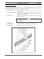
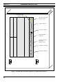
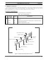
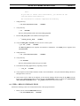
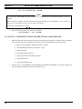
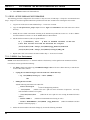
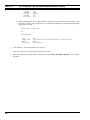
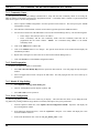
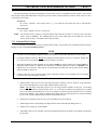
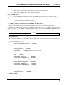
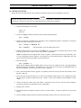
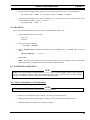
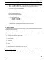
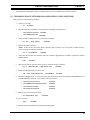
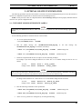
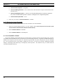
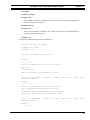
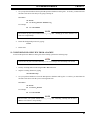
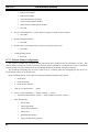
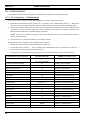
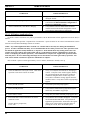
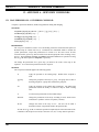
5.2.3 Rear Panel Connectors
Figure 1 shows the locations of the connectors on the Network Manager Workstation rear panel. The following
paragraphs describe the purpose of the connectors used by a typical Network Manager workstation. For a detailed description
of all connections on the rear panel, refer to the accompanying HP User’s Guides.
•
Power Cord Connector
Plug the workstation’s power cord into the power cord connector to provide AC
power to the system.
•
802.3 Network Connectors
The ThickNet LAN AUI or LAN-TP (twisted pair) connector is used to connect the
workstation to an 802.3 (Ethernet) network. Workstations connecting to a ThinLAN
network require an external transceiver.
•
SCSI Connector
The SCSI connector is used to connect to the workstation peripherals such as the CDROM and DDS Tape Drive.
NOTE
NOTE
When attaching external SCSI devices, be sure to terminate the last device on the
external SCSI bus. If no devices are attached, the SCSI connector does not
require a terminator.
•
PS2 Connectors
The PS2 connectors provide an interface for the workstations keyboard and mouse.
•
Monitor Connector
The Monitor video cable connects the monitor to the workstation.
•
Modem (RS-232)
Connects an external modem to the Network Manager.
Figure 1 - HP 9000 - 700 Series Workstation Rear Panel Connectors
17
LBI-39171
HARDWARE INSTALLATION
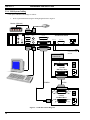
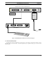
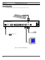
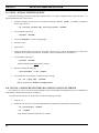
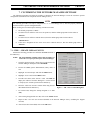
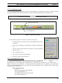
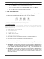
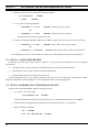
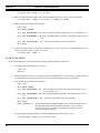
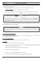
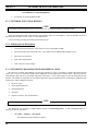
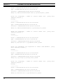
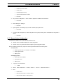
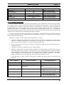
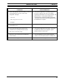
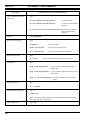
5.2.4 NM0 System Cabling
Cable up the NM0 Network Manager as follows:
1.
Hook- up the Workstation using the cabling diagram shown in Figure 2.
Modem (Optional)
Audio
Out
In
Line
Out
RS-232
Mouse
Parallel
Monitor
Keyboard
SCSI-2 Single Ended
712/60 Work Station
LAN-TP
LAN AUI
Connect to TCP/IP
Network
K2291
TERMINATOR
C1521B
DDS Tape Drive
C2908A
K2296
C2943A
CD-ROM Drive
Figure 2 - 712/60 Interconnect Diagram
18
HARDWARE INSTALLATION
LBI-39171
5.3 NM1 CONFIGURATION
The NM1 system is the base configuration for systems with three (3) users and up to 2000 network elements or five (5)
users and 1000 or less network elements. The NM1 configuration may be expanded to manage up to three (3) users with
10,000 network elements or five (5) users and 5,000 network elements.
5.3.1 Basic NM1 Configuration Hardware
The following hardware components are included with the basic NM1 package:
Table 3 - Basic NM1 Configuration Hardware
q
HP PART
NUMBER
OPTION
A2429A
DESCRIPTION
HP9000 - 800 Series Business Server, Model G60
includes the following:
A2980A
G60 - 96 MHz CPU with 2 megabyte cache
C1064WZ
ABA
C1064W 700/96 Console with white screen
A2516AZ
ODU
128 megabytes RAM
A2441A
ODS
LAN Personality card for base system I/O, includes 2 serial ports,
single-ended SCSI-2 interface, and pre-configured 802.3 ThinLAN.
A3087A
ODZ
Two (2) Internal Hard Disk Drives - 2 gigabytes SE SCSI-2
A3183A
ODZ
4mm DDS Internal Tape Drive - 4 gigabyte with data compression
A3184A
ODZ
Internal CD-ROM Drive - 650 megabytes
5.3.2 NM1 Upgrade Options
The NM1 configuration can be enhanced by adding additional RAM in 128 megabyte segments to a maximum RAM size
of 784 megabytes. Upgrading to the G70 Business server will permit the NM1 configuration to support up to 25 users with
2500 managed network elements.
Table 4 - NM1 Hardware Upgrade Options
q
q
PART
NUMBER
OPTION
DESCRIPTION
A2516A
ODZ
128 megabyte memory module
A2977
875
G70 Dual processor upgrade
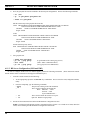
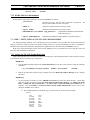
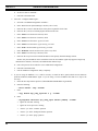
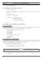
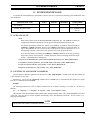
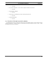
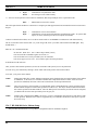
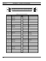
5.3.3 NM1 System Cabling
Cable up the NM1 Network Manager as follows:
1.
Connect power cord and Ethernet cable to server.
19
LBI-39171
HARDWARE INSTALLATION
Term Power Light
(Normal = Off)
Term
Power
SCSI
Self
Test
SCSI Self Test Light
(Normal = Off)
SCSI-2 (Single Ended)
SCSI Connector
Console Connector
Port 0
Console
Support Modem
Connector
Port 1
Modem
Console /
LAN
Self
Test
Console/LAN Self
Test Light
(Normal = Off)
LAN AUI Connector
LAN AUI
ThinLAN Connector
Thin LAN
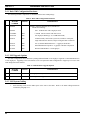
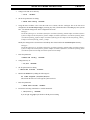
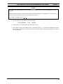
Figure 3 - HP 9000 - 800 Series Model G, Business Server Rear Panel Connectors
20
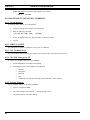
HARDWARE INSTALLATION
LBI-39171
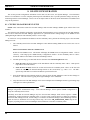
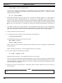
A2442A LAN I/O Card (Part of 9000/800 Server)
SCSI-2 Single Ended
Port 0
Console
Port 1
LAN AUI
Thin LAN
Modem
K2291
TERMINATOR
Transceiver
Keyboard
Datacomm
Connector
Printer Connector
Rear of Monitor
Connect to TCP/IP
Network
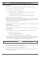
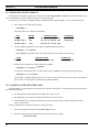
Figure 4 - HP 9000/800, Model G, Business Server Interconnect Diagram
5.4 NM2 CONFIGURATION
The NM2 system is the base configuration for systems with five (5) users and up to 10,000 network elements or ten (10)
users and 5,000 or less network elements. The NM2 configuration may be expanded to manage up to 25 users and 1,000
network elements.
21
LBI-39171
HARDWARE INSTALLATION
5.4.1 Basic NM2 Configuration Hardware
The following hardware components are included with the basic NM2 package:
Table 5 - Basic NM1 Configuration Hardware
q
HP PART
NUMBER
OPTION
A2429A
DESCRIPTION
HP9000 - 800 Series Business Server, Model G60
includes the following:
A2980A
G60 - 96 MHz CPU with 2 megabyte cache
C1064WZ
ABA
C1064W 700/96 Console with white screen
A2516AZ
ODU
128 megabytes RAM (qty: 4; 512 MB total RAM)
A2441A
ODS
LAN Personality card for base system I/O, includes 2 serial ports,
single-ended SCSI-2 interface, and pre-configured 802.3 ThinLAN.
A3087A
ODZ
Two (2) Internal Hard Disk Drives - 2 gigabytes SE SCSI-2
A3183A
ODZ
4mm DDS Internal Tape Drive - 4 gigabyte with data compression
A3184A
ODZ
Internal CD-ROM Drive - 650 megabytes
5.4.2 NM2 Upgrade Options
The NM2 configuration can be enhanced by adding additional RAM in 128 megabyte segments to a maximum RAM size
of 784 megabytes. Upgrading to the G70 Business server will permit the NM2 configuration to support up to 25 users with
2500 managed network elements.
Table 6 - NM1 Hardware Upgrade Options
q
q
HP PART
NUMBER
OPTION
DESCRIPTION
A2516A
ODZ
128 megabyte memory module
A2977
875
G70 Dual processor upgrade
5.4.3 NM2 System Cabling
1.
22
Interconnecting cables for the NM2 system is the same as the NM1. Refer to the NM1 cabling instructions
contained in paragraph 5.3.3.
HARDWARE INSTALLATION
LBI-39171
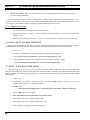
5.5 REMOTE X-STATIONS
At least one (1) HP “X” Station is required when using an HP Server setup. However multiple X-Stations will permit
remotely executing OpenView sessions on the Network Manager. The Network Manager requires one copy of the HP
Enware X Station software (ver. 3.5 or later) to be resident for support of one or more “X” Stations.
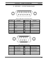
5.5.1 HP “X” Station Hardware
The following hardware components are included with the HP “X” Station package:
Table 7 - HP “X” Station Hardware
q
q
q
HP PART
NUMBER
OPTION
DESCRIPTION
C3253A
171
ENVIZEX “I” series 7Hz X Station with 17-inch color monitor (1024 x 768
resolution).
C2737A
ABA
ENVIZEX PC101/102 Keyboard kit with PS2 Interface (A2840-60201) and two
(2) power cords (8120-1378).
C2747A
OD1
X-Station 16 megabyte memory module.
Keyboard PS2 Connector
Monitor Connector
Power Cord
Connector
Parallel Connector
HP-HIL
(Audio in/out)
Thin LAN Connector
Mouse PS2 Connector
RS-232 (modem) Connector
LAN AUI Connector
LAN TP Connector
Figure 5 - ENVIZEX X-Station Rear Panel Connectors
23
LBI-39171
HARDWARE INSTALLATION
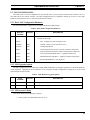
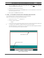
5.5.2 X-Station Cabling
1.
Cable the X-Station into the system according to diagram shown in Figure 6.
ENVIZEX X-Station
Keyboard
10BaseT
Thin LAN
LAN AUI
PARALLEL
RS-232
VIDEO
Connect to TCP/IP
Network
Figure 6 - 712/60 Interconnect Diagram
24
Mouse
HP-HIL
INITIAL SOFTWARE INSTALLATION
LBI-39171
6. INITIAL SOFTWARE INSTALLATION
Under normal circumstances all necessary software is preloaded and the system setup prior to installation at the
customer’s site. After which the Ericsson System Engineer and the customer need only customize the system to the
customer’s specific requirements.
However, if the factory is unable to preload all the required software, or if only the application package is purchased,
then it may be necessary to perform the initial installation tasks. The following procedures provide step-by-step instructions
for installing the system software in the field.
NOTE
Several components of the EDACS Network Manager requires licenses for proper operation. OpenView requires a
license from HP before it can be loaded. The EDACS Network Manager application can be loaded without the licenses
but is not operational. Permanent licenses are obtained from Ericsson. TSSterm can be loaded with a temporary license
good for 10 minute sessions. Permanent licenses are obtainable from Thursby Software Systems.
To obtain the TSSterm license, FAX the completed Registration form contained in the software box to the Thursby
Software Systems. This form requires the software package serial number and the Machine Identification Number
returned from “uname -i”.
To obtain the EDACS licenses, retrieve the target ID as specified by the procedure in this manual. FAX this information
on the form included with this manual.
To obtain the OpenView license, FAX the form located in the shipping box for OpenView. It requires the host name and
IP address.
NOTE
NOTE
Observe the following path and device names when referring to the Tape drive and the CD-ROM:
Tape Drive:
NM0 CD-ROM:
NM1 and NM2 CD-ROM:
/dev/rmt/0
·m
/dev/dsk/c20
·1d2s0
·
/dev/dsk/c2d0
·s2
6.1 STEP 1 -LOAD THE HP ENWARE X-STATION SOFTWARE (NM1 AND NM2 HP
SERVERS ONLY)
Use the following procedure when an X-Station is provided with the HP Server. If EDACS Network Manager is being
installed on an HP Workstation, skip to “Step 3 - Install OpenView Network Node Manager.” Prior to loading the Enware
software, only the dumb terminal is operational.
Ensure the HP Enware X-Station Software is Version 5.3 or later. To load the HP Enware X-Station Software, perform
the following:
1.
Apply power to the Network Manager system.
2.
Load the Enware software according to the instructions provided by the vendor.
25
LBI-39171
INITIAL SOFTWARE INSTALLATION
6.2 STEP 2 - SETUP X-STATION TERMINAL (NM1 AND NM2 HP SERVER ONLY)
Configure the X-Station for use with the Network Manager Server.
1.
Reboot the X-Station Terminal.
2.
While the terminal is rebooting, press and hold F12 until the configuration screen is displayed.
3.
Select the Terminal screen and set the Monitor field to match the monitor model number printed on the lower
left corner of the monitor.
4.
Set the Keyboard Layout field to PC.
5.
Select the Network -> General screen and set the following parameters:
6.
7.
•
Set Network Parameters field to “From Fields Below”.
•
Set File Server field to the IP Address of the Host server.
•
After the File Server IP Address, set the TFTP/NFS button to “TFTP”.
Select the Network -> Ethernet screen. Setup the Ethernet parameters for this X-Station Terminal.
•
Set the IP Address to the IP Address for this terminal.
•
Set Subnet Mask to the Subnet Mask for this terminal.
•
Set the Terminal Name to the Terminal Name for this terminal.
Select the Server screen:
•
Set Login field to “XDMCP Direct”
•
Set Login Host field to the IP Address of the Host server.
8.
Click on the OK button. The terminal will indicate it must reboot before the changes will go into effect. Click
on the REBOOT button if changes were made or click on the OK button to continue without making changes.
9.
The X-Station is now operational and should be used for the remainder of the installation process.
6.3 STEP 3 - INSTALL OPENVIEW NETWORK NODE MANAGER(NM0, NM1 AND NM2)
Use the following procedure to install the OpenView Network Node Manager (NNM). Refer to the HP OpenView
Network Node Manager Products Installation Guide for additional details.
NOTE: You must have an OpenView License prior to starting this procedure.
1.
Log in as root.
2.
Verify you have sufficient disk space by entering the following command:
> bdf
<ENTER>
The hard disk must have at least 65 MB available for the NNM and 17 MB for the EDACS Application.
3.
26
Insert the HP Network Node Manager CD-ROM (J2317A) into the CD-ROM drive.
INITIAL SOFTWARE INSTALLATION
4.
LBI-39171
Load the HP OpenView Installation utility fileset, OVIC, onto the disk drive by entering the following
command:
NM0 Workstation:
·1d2s0
· OVIC
> /etc/update -s /dev/dsk/c20
<ENTER>
NM1 or NM2 Server:
·s2 OVIC
> /etc/update -s /dev/dsk/c2d0
<ENTER>
NOTE: If the command errors out, the CD-ROM may be incorrectly added in the /etc/checklist file. If the CDROM is listed in /etc/checklist an attempt is made to mount it automatically on reboot. Delete the CD-ROM
from the /etc/checklist file and execute /etc/update again.
5.
Check for errors by entering:
> more /tmp/update.log
6.
<ENTER>
Enter the following to set PATH to include /usr/OV/bin.
> echo $SHELL
•
<ENTER>
If the display responds with sh or ksh, then enter the following commands:
> PATH=$PATH:/usr/OV/bin
> export PATH
•
<ENTER>
<ENTER>
If the display responds with csh, then enter the following command:
> set path=($path /usr/OV/bin) <ENTER>
7.
Enter the following command and install the Activation Key.
> /usr/OV/bin/ovkey
<ENTER>
If the key is valid, ovkey will install the key and display a message indicating you have a valid activation
key. In case of difficulty, refer to the HP OpenView NNM Installation Guide.
8.
Install NNM and the SNMP Management Platform (must load these in order):
·1d2s0
·
> /usr/OV/bin/ovinstall -p SNMPRUN -- -s /dev/dsk/c20
·1d2s0
·
> /usr/OV/bin/ovinstall -p NNMGR -- -s /dev/dsk/c20
9.
<ENTER>
<ENTER>
Check for errors by entering:
> more /tmp/update.log <ENTER>
Resolve any errors before proceeding.
10. From the user login, run OpenView.
> ovw &
C
<ENTER>
11. Verify OpenView is running.
27
LBI-39171
INITIAL SOFTWARE INSTALLATION
12. Select File->Exit and close OpenView.
6.4 STEP 4 - INSTALL EDACS NETWORK MANAGER APPLICATION
The EDACS Network Manager Application is distributed on a 90M DDS tape in tar (Tape Archive Recovery) file
format. The NM application requires 17 Mbytes of disk space on the hard drive. To load the application, perform the
following procedure:
NOTE: You must be logged in as root to execute this procedure.
1.
Insert the Network Manager Application data tape (350A1900, tape 1 of 2) into the tape drive.
2.
Copy the tar file from the tape to the disk by entering the following command:
·m /tmp/nm10
·5.tar <ENTER>
> cp -p /dev/rmt/0
NOTE: This takes a few minutes, the tape drive LED should be flashing green.
3.
Extract the Network Manager application from the tar file by executing the following command:
·5.tar
> tar -xvf /tmp/nm10
<ENTER>
NOTE: The file names being extracted will be echoed to the screen.
C
4.
Verify the EDACS directory now exists by entering the following:
> ls /usr/EDACS
<ENTER>
NOTE: Several directories should be listed on the screen.
6.5 STEP 5 - INSTALL LICENSING RUN TIME KIT
Perform the following steps to install the iFOR/LS Administrator Runtime Kit (ARK). The ARK is a component part of
the Network License System (NetLS).
NOTE
NOTE
a)
The Runtime Kit may be installed before the EDACS licenses are obtained, but they must be added per item 14
before the Network Manager Application software is accessible.
b) Licensing software requires an active LAN interface for proper operation.
c)
iFOR/LS is a commonly used licensing engine. The steps described in this procedure require halting the licensing
engine and should be executed by a trained System Administrator.
d) This procedure assumes the /usr/EDACS directory has been installed on the hard drive.
1.
Log into the HP-UX workstation where iFOR/LS ARK needs to be installed as root.
2.
Verify the appropriate files are present by executing the following UNIX commands:
> cd /usr/EDACS/netls <ENTER>
> ls
<ENTER>
The directory listing should show two (2) tar files named: file1, file2.
3.
Extract the install script:
> tar -xvf file1 <ENTER>
The directory listing should show five (5) files named: file1, file2, Copyright, README, and install.
28
INITIAL SOFTWARE INSTALLATION
4.
Verify that there are no users logged into the workstation using tools that require iFOR/LS licenses.
> users
5.
LBI-39171
<ENTER>
Determine the process ID for any currently executing iFOR/LS license database processes.
> ps -ef | more
<ENTER>
Search for Local Location Broker Daemon, llbd, the Global Location Broker Daemon, glbd, the iFOR/LS
License Server Daemon, netlsd, and the non-replicatable Global Location Broker Daemon, nrglbd processes.
6.
Write down the process ID for each active process found.
7.
Terminate each active process found by executing:
> kill -9 processID
<ENTER>
8.
Repeat step 5 and verify the four processes are no longer active.
9.
Install the iFOR/LS ARK by executing the following from the /usr/EDACS/netls directory:
>
./install
-d
/usr/EDACS/netls <ENTER>
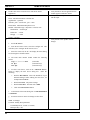
Executing this file will initiate the following script. Respond to all prompts according to system requirements:
The NetLS Server Kit product consists of one component:
NetLS Administrator Runtime Kit (ARK)
The complete NetLS product places all its trees into the /usr/lib
directory by default.
Symbolic links are then used to point to the
parts of the product that are required in standard locations (for
example, include files in /usr/include and manpages in /usr/local/man).
New top level [/usr/lib]:
<ENTER>
Do you want see a commentary as NetLS_ARK is installing [n]?
Do you want to use the NetLSd from HP [default no]?
“n”
“no”
This may take some time please be patient
Do you want netlsd started automatically when the machine boots [n]? “y”
HP NetLS already installed.
Do you want to use NetLS from HP [No]? “No”
NCS must be properly configured and initialized for NetLS to function
properly.
Checking cell name configurations. Please wait.......
29
LBI-39171
INITIAL SOFTWARE INSTALLATION
A NCS location broker configuration ordinarily contains one or more
Global Location Broker daemons belonging to one GLB cell, known as the
default cell. Most configurations use the default cell.
For some sites, it is desirable to assign some machines to an
alternate cell, where the GLB object has a different identification.
There are already existing GLB cells on this network: You may choose
to join one of them, or you may create a new one for this machine.
You must choose which cell you wish this system to belong to.
Press enter for a list of available cells.
The following GLB servers were found in alternate cells:
Svr_Name
Type of Server
Cell_Name
Uuid
You have four options:
1) Continue with installation without choosing a Cell_Name.
2) Use the default for the system Cell Name.
3) Create a new alternate cell for the system Cell Name.
4) Choose an existing alternate cell for the system Cell Name.
WARNING:
If you continue[1] the install without choosing a Cell Name then
NetLS will not function. If you do not understand these options input
[1] to continue and consult your system administrator or the
documentation Managing NCS Software
Please indicate your choice [1,2,3,4]: “3”
Will create new alternate GLB cell for this system.
Continuing setup...
After this installation has been done, you must run the
/usr/lib/netls/conf/netls_first_time shell script. It contain the
commands needed to initialize NCS and to start up the NCS and NetLS
daemons the first time. After that, the daemons will start
automatically whenever the system is booted. The llbd daemon will be
started after running /usr/lib/netls/conf/netls_first_time.
The glbd daemon will be started after running
/usr/lib/netls/conf/netls_first_time.
The netlsd daemon will be started after running
/usr/lib/netls/conf/netls_first_time.
The NCS setup completed successfully
Install of NetLS_ARK finished
30
INITIAL SOFTWARE INSTALLATION
LBI-39171
Done.
If you want to remove this installation, you should run the
/usr/lib/netls/conf/remove.sh
The installation of NetLS completed successfully
7.
Change directory:
> cd /usr/lib/netls/conf
8.
<ENTER>
Verify directory:
> ls
<ENTER>
Directory listing should include a file named netls_first_time.
9.
Execute netls_first_time to start iFOR/LS licensing daemons.
>
./netls_first_time
<ENTER>
10. Verify that llbd, glbd, and netlsd processes are active on the system.
> ps -ef | more
<ENTER>
The llbd and glbd processes originate from /etc/ncs or /usr/etc/ncs. The netlsd process originates from
/usr/lib/netls/bin.
11. Change directory:
> cd
/usr/lib/netls/bin
<ENTER>
12. Verify directory:
> ls <ENTER>
Directory listing should include the ls_tv executable.
13. Test iFOR/LS licensing application by requesting a license.
>
./ls_tv
<ENTER>
14. Verify output to screen includes Gradient, not HP, version information. Verify that Network Manager Station is
among the active server list.
15. Now licenses can be added to the database for the Network Manager Station using the ls_admin (network
license server administration) utility found in directory /usr/lib/netls/bin. Refer to section 10.2, INSTALLING
THE LICENSE PASSWORD and the /ls_admin information on the License PAK.
.
6.6 STEP 6 - RELOCATE EDACS FILES
Perform the following to move the various EDACS files to their proper directories.
1.
Ensure you are in the /usr/EDACS/bin directory.
> cd /usr/EDACS/bin
<ENTER>
31
LBI-39171
2.
INITIAL SOFTWARE INSTALLATION
Enter the following command to move all files to their appropriate directory.
>
./edacsInstall
<ENTER>
The display will respond “Installing EDACS from /usr/EDACS.”
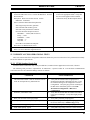
6.7 STEP 7 - INSTALL TSSTERM SOFTWARE
Use the following procedure to install the TSSterm software. TSSterm provides the terminal emulation into the System
Manager platform.
1.
Fill out the Registration card and FAX to designated address for a permanent key (the temporary key is good for
only 10 minutes).
2.
Enter the following as root and verify responses:
> /etc/update -s /dev/rmt/0
·m TSSTERM
a)
Display shows the TSSterm copyright notice.
b) Press <Return> to continue.
c)
The display shows the following:
TSSterm License Manager Customization
This procedure will tailor the your node to run the TSSterm License Manager.
Do you want to configure TSSTERM License Manager?
d) Enter “YES”
e)
Before continuing, please be ready to answer the following questions:
Autostart at boot:.............................[Y]
License manager key file:................[ /etc/tss_license]
License manager log file: ................[/tmp/tss_lmgr.log]
Verbose environment variable: .......[0]
f)
Press <Return> to continue.
g) The display provides instructions on requesting permanent key (1-800-283-5070).
h) Autostart at boot time:............................YES
i)
Key file (return = /etc/tss_license): ........<Return>
j)
Log file (return = /tmp/tss_lmgr.log):.....<Return>
k) Verbose (return = 0):..............................<Return>
l)
Verify inputs. Is this correct? ................YES
m) Installation complete.
Press RETURN to continue.
3.
<Return>
Enter the following to check for errors:
> more /tmp/update.log
<ENTER>
If any errors are detected, refer to the Troubleshooting Section in the TSSterm manual.
32
INITIAL SOFTWARE INSTALLATION
4.
LBI-39171
Modify run level (inittab file) for TSSterm as follows:
> chmod 644 /etc/inittab <ENTER>
5.
Invoke vue pad by entering /usr/vue/bin/vuepad /etc/inittab, vue pad is similar to notepad on a
PC. Edit the /etc/inittab file by;
•
Find the line: tlmg:2:once /etc/rc.lmgr #Start tsslmgr daemons
•
Change the line to read: tlmg:4:once /etc/rc.lmgr #Start tsslmgr daemons
> chmod 444 /etc/inittab <ENTER>
6.8 STEP 8 - CONFIGURE X-STATION (IF PRESENT) TO USE TSSTERM
1.
Execute /usr/EDACS/bin/termInstall to convert TSSterm to X-station font format.
> cd /usr/EDACS/bin
> terminstall
<ENTER>
<ENTER>
2.
At each X-Terminal set up the font server by entering the configuration screen (press and hold F12 if the XTerminal is booted and your logged into HP-Vue).
3.
Select the “Server” option. You should see the Font Path options list similar to that shown below. (It is likely
several fonts will be explicitly listed).
./fonts/iso_8859.1/75dpi/
./fonts/iso_8859.1/10··0dpi/
./fonts/misc/
/rom/fonts/default/
4.
At the end of the “./fonts/misc/” line, press the <ENTER> key to start a new line. Add the following TSSterm
fonts to the font path window:
./fonts/tssterm/75dpi/
./fonts/tssterm/10·0·dpi/
5.
Click on the OK button. The terminal will indicate it must be rebooted for the changes to take effect. Click on
the REBOOT button to reboot the X-Station and load the new fonts.
6.
Repeat items 2 thru 5 for each X-Station connected to the system.
33
LBI-39171
INITIAL SOFTWARE INSTALLATION
6.9 STEP 9 - INSTALL TSSTERM LICENSE
Perform the following procedures to install the TSSterm license. To install a temporary license, start with item 1. To
install a permanent license, skip to item 6..
1.
Install the temporary license (key) by entering the following command: (NOTE: If installing a permanent
license, skip to item 6.)
> cp /etc/tss_license.tmp /etc/tss_license <ENTER>
2.
Verify TSSterm will execute.
> tssterm
<ENTER>
3.
Answer “CONTINUE” to license warning popup.
4.
Select File->Exit
5.
Skip to Item 8.
6.
Using the HP Vue Editor (described in the Editor Options section), edit the tss_license file to include the
permanent license number from the FAX. Remember, spaces and capital letters are significant.
7.
Verify TSSterm will execute.
> tssterm
<ENTER>
TSSterm should execute without license warning.
8.
Reboot by entering the following:
> /etc/shutdown -r now <ENTER>
9.
Verify TSSterm license manager is started at boot by entering:
> ps -ef | grep lmgr
<ENTER>
Display responds with: includes /etc/tsslmgr process
6.10 STEP 10 - CONFIGURE NETWORK MANAGER STATION FONT SERVER
If you plan to use a PC to access the Network Manager system, then the Network Manager Font Server containing the
fonts added by TSSterm must be properly configured.
To setup and use the Font Server on HP-UX 9.0 execute the following procedure:
1.
Login as root.
2.
Ensure the X11 font server exists on the HP machine by looking for the font and font server directories.
> cd /usr/lib/X11 <ENTER>
> ls
<ENTER>
Verify that the fs and fonts directories are available.
34
INITIAL SOFTWARE INSTALLATION
3.
Change to the font server directory:
> cd fs
4.
LBI-39171
<ENTER>
Set the file permissions for editing:
> chmod 644 config <ENTER>
5.
Using the HP Vue Editor (refer to the HP VUE User’s Guide), edit the “catalogue” line in the font server
configuration file /usr/lib/X11/fs/config by removing any fonts you DO NOT have and adding any fonts you DO
have. The default catalogue line in the configuration file reads:
catalogue =
/usr/lib/X11/fonts/type1.st,/usr/lib/X11/fonts/ifo.st,/usr/lib/X11/fonts/hp_roman8/75dpi/,/usr/lib/X11/fonts/is
o_8859.1/75dpi/,/usr/lib/X11/fonts/iso_8859.1/100dpi/,/usr/lib/X11/fonts/misc/,/usr/lib/X11/fonts/hp_kana8
/,/usr/lib/X11/fonts/hp_japanese/75dpi/,/usr/lib/X11/fonts/hp_korean/75dpi/,/usr/lib/X11/fonts/hp_chinese_
s/75dpi/,/usr/lib/X11/fonts/hp_chinese_t/75dpi/
Modify the catalogue file as shown below and add any other fonts found in the /usr/lib/X11/fonts directory:
catalogue =
/usr/lib/X11/fonts/type1.st,/usr/lib/X11/fonts/ifo.st,/usr/lib/X11/fonts/hp_roman8/75dpi/,/usr/lib/X11/fonts/is
o_8859.1/75dpi/,/usr/lib/X11/fonts/iso_8859.1/100dpi/,/usr/lib/X11/fonts/misc/,/usr/lib/X11/fonts/hp_kana8
/,/usr/lib/X11/fonts/tssterm/75dpi,/usr/lib/X11/fonts/tssterm/100dpi
3.
Reset the permissions
> chmod 444 config
4.
<ENTER>
Change directory to:
> cd /etc <ENTER>
5.
Set file permissions for editing
> chmod 644 inittab
6.
<ENTER>
Edit the /etc/inittab file by adding the following line:
fs :2345:respawn:/usr/bin/X11/fs
This will run the font server at all typical system run levels.
7.
Reset the permissions
> chmod 444 inittab <ENTER>
8.
Execute the following command to re-read the inittab file.
> /etc/init q
<ENTER>
If you do a ps -ef | grep fs you should see the fs process running.
35
LBI-39171
INITIAL SOFTWARE INSTALLATION
6.11 STEP 11 - INSTALL PC-XWARE HOST SOFTWARE (XREMOTE)
This procedure installs the PC-Xware software from the 350A1900 tape 2 of 2. This software provides access to the
Network Manager application from a remote location for the purpose of troubleshooting, configuring , and interfacing with
the Network Manager even if the LAN is inoperative.
The following instructions will configure the Network Manager station. See the Remote Access section for instructions
on configuring PCs and Modems.
1.
Insert data tape 350A1900 tape 2 of 2 into the tape drive.
2.
Ensure you are logged in as ROOT. (Password required.)
> su <ENTER>
3.
Copy the PC-Xware tar file from the tape using the following command:
·m /tmp/pcxware.tar <ENTER>
> cp -p /dev/rmt/0
4.
Extract the PC-Xware host software using the following command:
> tar -xvf /tmp/pcxware.tar /usr/pcxware
5.
<ENTER>
Verify that there is now a /usr/pcxware directory that contains the following subdirectories and files:
/application - xinitremote, Xremote, (already extracted from hpux10.tar)
/manpages - Xremote.1, xinitremote.1 (already extracted from manpages.tar)
/manual - *.ps files (postscript format)
/user_setup - .cshrc (example user .cshrc file)
/utilities - x* executables (already extracted from hp.tar)
6.
Install the PC-Xware host software, use the following command:
> /usr/pcxware/user_setup/pcxwareInstall
7.
<ENTER>
Remove the temporary PC-Xware tar file using the following command:
> rm
/tmp/pcxware.tar
<ENTER>
6.11.1 HP Workstation Configuration
HP’s standard configuration for serial port communication is set up as follows:
•
•
•
•
•
9600 baud rate
7 data bits
1 stop bit
EVEN parity
XON/XOFF flow control
This configuration must be modified for use with PC-Xware to the following:
•
•
•
•
•
36
19200 baud rate, if using an HP Workstation (9600 for an HP Server)
8 data bits
1 stop bit
NO parity
NO flow control (preferred for efficiency, but may be necessary due to heavy line noise.)
INITIAL SOFTWARE INSTALLATION
LBI-39171
The UNIX command “stty” allows a user to view or set the options for a terminal port. This command can be used as a
tool to aid in troubleshooting modem configuration problems. A sample stty output might look like this:
zappa:/> stty -a
speed 19200 baud; line = 0; susp = ^Z; dsusp <undef>
rows = 0; columns = 0
intr = ^C; quit = ^\; erase = ^H; kill = ^U; swtch = ^@
eof = ^D; eol = ^@; min = 4; time = 0; stop = ^S; start = ^Q
-parenb -parodd cs8 -cstopb hupcl cread -clocal -loblk -crts
-ignbrk brkint ignpar -parmrk -inpck istrip -inlcr -igncr icrnl -iuclc
ixon ixany ixoff -rtsxoff -ctsxon -ienqak
isig icanon iexten -xcase echo echoe echok -echonl -noflsh
opost -olcuc onlcr -ocrnl -onocr -onlret -ofill -ofdel tostop
The instructions to configure an HP-700 series workstation, running HP-UX 9.x, are detailed in the following list.
NOTE: Superuser privilege is required to perform these instructions!
1.
Connect the modem into the serial port on the back of the CPU case. Verify that the AC power cable is
connected. Verify that the phone line goes into the modem. Verify that the serial communication cable
connects the modem to one of the HP’s serial ports. Verify that the modem is powered ON.
2.
Login and run the SAM utility. To add a modem to the known devices, go to the Peripheral Devices>Terminals and Modems->Actions->Add Modem... screen. Press OK to a popup about no terminals or modems
found, if applicable. Press OK on the popup window about port availability. Configure the following:
Modem Configuration Parameter
Recommended Value
(Defaults in BOLD)
Mux/Serial Card
Port Number
Speed (baud rate)
Use Device for Calling Out
Receive In-coming Calls (start getty process)
CCITT Modem (used for international calling)
Choose one from the list given or take default.
Choose one from the list given or take default.
19200
NO
YES
NO
Press OK to add the modem. Another popup should appear, stating that a new device file was created. Press
OK and exit SAM. Verify that a new getty process has been started for the modem by executing this command
(a sample output has also been provided):
> ps -ef
root
root
root
| grep getty
1359
28831
1
245
1
0
1068
1
0
14:15:10
May 7
14:12:44
ttyp2
?
0:00
grep getty
console 0:00
/etc/getty -h console console
0:00
/etc/getty -h ttyd00 19200
NOTE: ttyd00 is the device file name given by SAM. 19200 is the stated baud rate.
3.
Verify that the following line has been put into the /etc/inittab file. If not seen, put it there.
a0:4:respawn: /etc/getty -h ttyd00 19200
where ttyd00 is the device file name given in SAM, and 19200 is the desired baud rate.
If the inittab file was modified, execute this command for the changes to take effect:
> init q
37
LBI-39171
4.
INITIAL SOFTWARE INSTALLATION
Next, the gettydefs file must be modified to the desired port configurations. Execute the following commands:
> cd
/etc
> cp
-f gettydefs gettydefs.sav
> chmod 777 gettydefs
Edit the 19200 setup in the gettydefs file from this:
19200 # B19200 HUPCL IGNPAR PARENB ICRNL IXON OPOST ONLCR CS7 CREAD
ISIG ICANON ECHO ECHOK PARENB ISTRIP IXANY TAB3
# B19200
SANE CS7 PARENB ISTRIP IXANY TAB3 HUPCL
#login: #19200
to this:
19200 # B19200 HUPCL IGNPAR ICRNL OPOST ONLCR CS8 CREAD
ISIG ICANON ECHO ECHOK ISTRIP IXANY TAB3
# B19200
SANE CS8 ISTRIP IXANY TAB3 HUPCL
#login: #19200
and the 9600 setup entry to this:
9600 # B9600 HUPCL IGNPAR ICRNL OPOST ONLCR CS8 CREAD
ISIG ICANON ECHO ECHOK ISTRIP IXANY TAB3
# B9600
SANE CS8 ISTRIP IXANY TAB3 HUPCL
#login: #9600
5.
Save gettydefs file.
>
>
>
>
chmod 444 gettydefs
ps -ef | grep getty
kill <PID>
ps -ef | grep getty
(to get the PID of the current getty process)
(where <PID> is PID found above)
(verify getty has a new PID number)
6.11.2 HP Server Configuration (NM1 and NM2)
In order to configure an HP server for modem support, perform the following instructions (These instructions assume
that the modem will be connected into the Support Link Modem port.) :
1.
2.
From the console terminal, do the following:
•
At the login prompt, press the <Control-B> key combination. This executes the CM (Configuration Menu)
utility.
•
From the CM prompt, type the following commands:
> help
This provides a listing of the CM commands.
> ca
This is used to configure the modem port.
Enter: Baud rate = 9600
Protocol = Bell
System Identification =
> ur
This is used to unlock the remote access port.
> co
Quit CM. Return to login prompt.
Execute all the instructions listed in the HP Workstation Configuration section.
NOTE: The Support Link Modem port has a maximum baud rate of 9600. Use a baud rate of 9600, instead of
19200, when executing the HP Workstation Configuration instructions.
38
INITIAL SOFTWARE INSTALLATION
LBI-39171
6.12 STEP 12 - INSTALL CEC/IMC MANAGER HP-UX CLIENT SOFTWARE
This procedure installs the CEC/IMC Manager HP-UX Client Software from the 350A2001 data tape into the Network
Manager. The CEC/IMC Manager HP-UX client application allows the Network Manager user to remotely access the
CEC/IMC Manager. This application requires approximately 21 Mbytes of disk space on the hard drive.
1.
Insert data tape 350A2001 into the tape drive.
2.
Ensure you are logged in as ROOT. (Password required.)
> su
3.
<ENTER>
Copy the CEC/IMC Manager HP-UX client tar file from tape to the hard disk by entering the following:
·m /tmp/imcmgr_hp.tar
> cp -p /dev/rmt/0
4.
<ENTER>
Extract the CEC/IMC Manager HP-UX client software from the tar file /tmp/imcmgr_hp.tar by entering
> tar -xvf /tmp/imcmgr_hp.tar /usr/IMC_EDACS
5.
Change directory to:
> cd /usr/IMC_EDACS/bin
6.
<ENTER>
<ENTER>
Enter the following command:
>
./edacsInstallIMC
<ENTER>
This establishes the necessary soft links pointing to the right executables and/or scripts to run your application.
NOTE: If you reinstall or upgrade the EDACS Network Manager application software, you must also repeat
this step before successful invocation of CEC/IMC Manager HP-UX client application.
7.
Remove the temporary CEC/IMC Manager HP-UX client software tar file by entering:
> rm /tmp/imcmgr_hp.tar
8.
<ENTER>
Verify the file permissions for file /dev/lan0 are set to mode 755 by entering the following command:
·
> chmod 755 /dev/lan0
<ENTER>
This ensures the CEC/IMC Manager HP-UX client (an HP DCE - Distributed Computing Environment client)
can communicate with the server residing on the Windows NT platform.
6.13 STEP 13 - PERFORM FULL SYSTEM IMAGE BACKUP
At this point all software has been loaded and the system is ready for customization. However, we strongly recommend
you make a full system image backup tape before proceeding with the customization.
Perform a full System Image Backup using the following procedure:
1.
As root user: Use console login.
> /etc/shutdown now
<ENTER>
System will shutdown and come back up in single-user mode. If asked what terminal type, press <Enter>
2.
·m).
Insert the System Image Backup Tape into the tape drive (assume device name = /dev/rmt/0
3.
Enter the following commands:
> cd / <ENTER>
39
LBI-39171
INITIAL SOFTWARE INSTALLATION
·m
> tar -cvf /dev/rmt/0
.
<ENTER>
NOTE
NOTE
One 90mm tape should handle the entire backup and the backup process will take approximately one hour to
complete.
When the backup is complete, carefully label all System Image backup tapes as “Sysddmmmyyyy Vol # (number of
this tape) of # (total number of tapes it took to complete the backup)”.
For example: Sys12DEC1994 Vol 1 of 4.
3.
Enter the following command to reboot the workstation.
> /etc/shutdown -r now
<ENTER>
6.14 STEP 14 - COMPLETING THE SOFTWARE INSTALLATION PROCESS
1.
2.
40
Gather the following software packages and tapes and package them together for shipment with the equipment.
The customer, upon receipt, should store the software in an environmentally safe and secure location.
•
EDACS Network Manager Application Software (2 tapes).
•
CEC/IMC Manager HP-UX Client software (1 tape).
•
TSSterm Software.
•
HP X-Station Enware software.
•
OpenView Network Node Manager Software.
•
Unix Media Software.
•
System Image Backup Tape.
Proceed to the “CUSTOMIZING THE NETWORK MANAGER SOFTWARE” section and configure the
Network Manager according to the Network Manager Survey.
CUSTOMIZING THE NETWORK MANAGER SOFTWARE
LBI-39171
7. CUSTOMIZING THE NETWORK MANAGER SOFTWARE
The following procedures will allow the installer to customize the Network Manager to meet the customer’s specific
configuration as described in the completed Network Manager Survey.
NOTE
NOTE
The following procedures can only be completed after the Network Manager Survey has been properly annotated
with the customer’s specific configuration data.
When creating user accounts keep the following conventions in mind:
a.
The default group name is “users.”
b.
If a subset of users will have write access to OpenView, then the default group name for that subset is
c.
If a subset of users will have reduced menu set, then the default group name for that subset is
“nmwrite”.
“redmenu users”.
d.
If the user is designated to have write access and a reduced menu set, then the default group name is
“nmwrite”.
7.1 STEP 1 - CREATE USER ACCOUNTS
Perform the following procedure for each User Account identified in
the NM Survey.
NOTE: The environmental variables setup in this procedure are
vital to the successful operation of the Network Manager.
1.
Using the Password Utility, change the root password to the
Network Manager default password “NETMGR”.
2.
Execute the SAM (system administration) utility while in
root.
3.
Highlight “User and Groups” and click the OPEN button.
4.
Highlight “Users” and click the OPEN button.
5.
From the Users menu, select Actions -> Add. The SAM will
display the “Add User Account” Dialog box. Use this screen
to setup any user accounts specified in the NM Survey.
6.
Fill in the “Add User Account” window fields using the user
data obtained from the NM survey.
7.
For each account, change the “Startup Program” to C Shell
(csh).
8.
After entering the applicable user data, click on the APPLY button.
9.
Repeat 6 thru 8 for each user account identified in the Network Manager Survey (including the Support
Account).
Figure 7 - Add A User Account Dialog Box
10. After all users have been added, click on the OK button.
41
LBI-39171
CUSTOMIZING THE NETWORK MANAGER SOFTWARE
11. Select EXIT to return to the functional area.
7.2 STEP 2 - SETUP USER ACCOUNT PROFILE
The following procedure configures the user accounts. It may save time, if both Step 2 - Setup User Account Profile and
Step 3 - Setup User Account Login Environment are performed for each user account before selecting the next account.
1.
Log into one of the user accounts added in Step 1 - Create User Accounts.
2.
Copy the /usr/pcxware/user_setup template files for .login and .xinitremoterc into each remote user’s home
directory.
3.
Modify the user’s Shell environment according to the instructions provided in section 7.2.1 for the C SHELL
User Environment or section 7.2.2 for the KORN Shell User Environment.
4.
Edit the shell environment (.cshrc) as specified below:
if ( ! $?DISPLAY ) exit
# Exit if DISPLAY variable is NOT set
# All that follows will NOT be executed for rlogins!
/usr/bin/X11/xrdb -merge /usr/EDACS/app_defaults/TSSterm
/usr/bin/X11/xrdb -merge /usr/EDACS/config/C/XNm_add
5.
Repeat items 1 thru 4 for each user account created in Step 1 - Create User Accounts.
7.2.1 C SHELL User Environment
.
NOTE: In the instructions below, a “ ” character indicates “this directory” and is significant in command executions.
For each user created, perform the following:
1.
If C Shell is being used, either copy /usr/EDACS/config/C/.cshrc to the user’s home directory or edit the user
account .cshrc file as follows:
•
Coping the /usr/EDACS/config/C/.cshrc file to the user’s home directory:
.
> cp /usr/EDACS/config/C/ cshrc $HOME/
.
OR
•
Editing the user account:
Add the following statements to the .cshrc file:
> unset autologout
(to turn off disappearing windows)
> /usr/OV/bin
(Added to the user’s path for easier invocation of OpenView. All newly
created windows will have a new path.)
> /usr/lib/netls/bin
utilities.)
> setenv LANG C
(Added in the user’s path for ease in using the IFOR/LS license
(Added for internationalized text string to work.)
> setenv XAPPLRESDIR /usr/EDACS /app_defaults
Monitor to function properly.)
2.
42
(Added for MultiSite and Site
Ensure the current window reflects the changes by execute the following command:
CUSTOMIZING THE NETWORK MANAGER SOFTWARE
> source cshrc
LBI-39171
<ENTER>
7.2.2 KORN Shell User Environment
.
If Korn Shell is being used, edit the user environment profile file as follows:
> /usr/OV/bin
(Added in the user’s path for easier invocation of OpenView. All
newly created windows will have a new path
> LANG=“C”
(Added for internationalized text string to work.)
> export $LANG
(Added for internationalized text string to work.)
> XAPPLRESDIR=“/usr/EDACS /app_defaults”
> export $XAPPLRESDIR
(Added and for MultiSite and Site Monitor
to function properly.)
(Added and for MultiSite and Site Monitor to function properly.)
7.3 STEP 3 - SETUP USER ACCOUNT LOGIN ENVIRONMENT
The Network Manager platform can be customized to provide an EDACS icon on the HP VUE Front Panel which will
bring up a read-only version of OpenView by double clicking on the icon. The Network Manager can also be configured to
automatically bring down the OpenView and performance applications when the VUE front panel EXIT is selected.
Refer to the Login Environment section of the Network Manager Survey to determine the need to setup the VUE front
panel icon and configure the EXIT button.
7.3.1 Setting Up The VUE Format Panel Icon
Setup VUE front panel icon for each user account created using one of the following methods. This procedure sets up an
icon which will invoke a read-only copy of OpenView
METHOD 1:
1.
Copy the EDACS bitmap images from /usr/EDACS/bitmaps/C to the user’s home directory using the following
command:
> cp /usr/EDACS/config/C/vuewmrc
2.
.
$HOME/ vue/vuewmrc
<ENTER>
Depress the right mouse button in open workspace and select Restart Workspace Manager to have changes
take effect.
METHOD 2:
1.
Use this procedure to modify or create a $HOME/.vue/vuewmrc file in the users home directory. On line help
from Vue for this procedure is found under Front Panel and Workspace Manager -> Configure the Front
Panel -> Modify the Top or Bottom Row -> To add or delete a control from the top or bottom row. In
summary, select the Toolboxes ->General Toolbox->System Admin->EditVuewmrc action. You are now
editing the vuewmrc file as follows:
•
add CONTROL EDACS in the BOX Top {} portion of the file as shown in the example:
BOX Top
{
TYPE
CONTROL
CONTROL
CONTROL
CONTROL
CONTROL
CONTROL
SWITCH
CONTROL
primary
Clock
Date
Load
Style
EDACS
Help
Switch
Printer
43
LBI-39171
CUSTOMIZING THE NETWORK MANAGER SOFTWARE
CONTROL
CONTROL
CONTROL
CONTROL
HELP_TOPIC
Mail
Home
Toolboxes
Trash
FPTop
}
•
add the following lines after the BOX Bottom{} statement of the file as shown in the example. This
will cause a read-only copy of OpenView to be invoked with output put to a window titled OpenView
Output with a scroll bar.
#
# Regular Session: Top Row Controls
#
###
CONTROL EDACS
{
TYPE
PUSH_ACTION
IMAGE
HELP_STRING
}
44
button
f.exec "/usr/bin/X11/xterm -sb -title 'OpenView Output' -e /usr/OV/bin/ovw -ro &"
EDACS
"Invoke OpenView"
2.
Click on the File->Save menu options to save changes
3.
Click on the and File->Exit menu option to quit the edit session.
4.
Depress the right mouse button in open workspace and select Restart Workspace Manager to have changes
take effect.
CUSTOMIZING THE NETWORK MANAGER SOFTWARE
LBI-39171
7.3.2 Set Up Home Session
The following procedure configures the HP VUE Style Manager to automatically start with the standard Network
Manager style parameters and not those deliberately or accidentally changed during a previous operating session.
NOTE
NOTE
DO NOT have any applications open when performing this procedure.
EDACS Front Panel Icon
Style Manager icon
Figure 8 - OpenView Front Panel
Use the following procedure to start the user’s Home Session at login.
1.
From the OpenView front panel, select the Style Manager button on the
Front Panel.
2.
Choose the Style Manager’s Startup button to display the Startup dialog
box..
3.
Select the “Return to Home Session” and ensure the Logout Confirmation
Dialog is set “On.”
4.
Select “Set Home Session...”
5.
Click on OK to return to the Style Manager.
6.
Select File->Exit to return to OpenView.
7.3.3 User Setup for PC-Xware
The xinitremote file is the first file activated during an X session. It is responsible Figure 9 - Style Manager Startup
Panel
for executing the main XRemote file. The X processes look for a user-defined list of X
applications to start. These applications are specified in the .xinitremoterc file, located in the user’s home directory. A
sample .xinitremoterc file is shown below. Note that only the last file should be run in the foreground. Create this file for
each user. We recommended putting an xterm session as the last X application to start. When the xterm is closed, all the
other applications will also close.
> more .xinitremoterc
#!/bin/csh
# Run initial applications in the background.
xclock -display $DISPLAY &
# Last application must run in the foreground.
xterm -display $DISPLAY -ls
45
LBI-39171
CUSTOMIZING THE NETWORK MANAGER SOFTWARE
NOTE: The command ovw -ro & could be added to the initial application section if you desire to have the
OpenView startup immediately.
Be aware that the X session display is identified by a display number appended to the HP host name, such as
192.168.201.2:d.0. Where “192.168.201.2” is the default Network Manager IP address and “d” is the display number. (For d
= 0, the display is the local host terminal.) The display number will change between sessions.
7.3.4 Complete User Setup
1.
Verify the EDACS icon is displayed in the VUE Front Panel.
2.
Repeat the entire Step 3 - Setup User Account Login Environment for each User Account listed in the Network
Manager Survey.
3.
After all User Accounts created in Step 1 - Create User Accounts have been setup, proceed with the next step.
7.4 STEP 4 -SET UP VUE EXIT CONDITION
If specified in the Network Manager Survey, setup the VUE EXIT condition using the following procedure: When the
VUE EXIT button is selected, OpenView will automatically clean up Network Manager processes before exiting.
1.
Login as root.
2.
Save the current Xreset file to a temporary location using the following command:
> cp /usr/vue/config/Xreset /usr/vue/config/Xreset.org
1.
Copy the cleanexit file to the user configuration directory using the following command:
> cp /usr/EDACS/bin/cleanexit
/usr/vue/config/Xreset
7.5 STEP 5 - SETUP HOST NAME TABLE
Users may prefer to see the host names of remote devices instead of their IP Addresses. By setting up a Host Name
Table, the Network Manager can associate the host name with the IP Address and display the devices host name when menu
items are invoked. The following procedure allows you to set up the Host Name Table using data obtained from the Network
Manager Survey.
1.
Login as root.
2.
Run SAM (If the system is running HP VUE, you can run SAM using the action the action in the
System_Admin subdirectory of the General Toolbox.)
3.
In SAM, open:
•
46
Networking and Communications -> System-to-System Connectivity ->Internet Connectivity
4.
Choose ADD from the Actions menu.
•
Items 5 through 8 are to be performed for each remote device.
5.
Enter the IP Address in the “Internet Address” field.
6.
Enter the Host Name in the “Remote System Name” field.
7.
Enter comments, as required, in the “Comments” field.
CUSTOMIZING THE NETWORK MANAGER SOFTWARE
LBI-39171
8.
Click on the APPLY button to add the data to the Host Name Table. NOTE: Do not click the OK button,
clicking on the OK button will exit the process.
9.
Repeat items 5 through 8 for each remote device.
10. After the last device is entered, click on the CANCEL button to view to the finished table. Review the table
entries and verify that they are correct.
11. When complete, select EXIT from the File menu.
7.6 STEP 6 - CUSTOMIZING HP OPENVIEW NETWORK NODE MANAGER
Use the following procedure to configure the HP OpenView Network Node Manager:
NOTE: Be sure to log into an user account with read/write privileges.
1.
Logout of root by entering “exit”, and login as user.
2.
From the user login, run OpenView:
> ovw &
C
3.
Verify OpenView comes up with the EDACS Menu item present on the main menu bar and that it indicates this
is a read/write version (“Read/Write” is displayed in the lower left corner of the display).
If the EDACS Menu item is not present there was a serious problem with the EDACS Application installation.
Refer to the Troubleshooting section for additional information.
EDACS Menu item
Read/Write version
Figure 10 - OpenView Window
47
LBI-39171
CUSTOMIZING THE NETWORK MANAGER SOFTWARE
7.6.1 Community Names
The OpenView Network Node Manager (NNM) must be setup with the same community names for accessing the
EDACS elements as the EDACS elements have programmed in them. A community name is similar to a password and both
sides need to expect or use the same password.
1.
Select “Options->SNMP Configuration” from the OpenView main menu bar. This will open up the “SNMP
Configuration” window.
2.
Select Default “Global Default” with left mouse button to populate OpenView SNMP Parameters.
3.
For each device listed in the CEC/IMC/RCEC section of the Network Manager Survey, enter the following data:
•
In the “Target” field, enter the device’s IP Address.
•
In the “Community” and the “Set Community” fields, enter the Community Name that will be
programmed into the remote element. NOTE: We recommend using “edacs” as the default
Community Name.
4.
Click on the ADD button to add the data.
5.
Click on the APPLY button to save changes. The specific Nodes Section of the window should display the
information just added
6.
Repeat items 3 through 5 for each remote device listed in the Network Manager Survey.
7.
Click on CANCEL to exit the SNMP Configuration window.
7.6.2 Fault Propagation
In addition, propagation of faults are customizable.
1.
Select File->Describe/Modify Map from the OpenView main menu bar. This will popup the map description
window.
2.
Select “Propagate Most Critical” and press the OK button. This will propagate the most severe status up to
parent icons.
7.6.3 Disable IP Map Polling
1.
Select Options->Topology/Status Polling: IP...
2.
Turn off - Polling Master Switch, display responds: OK.
3.
Select File->Exit to close OpenView.
7.6.4 Event Configuration
The OV_Set_Status_Color must be set to “Don’t Log or Display.” This will reduce the chance of over filling the Event
Log under heavy loading conditions (large number of elements) and improves the system performance.
48
1.
From the OpenView Menu bar, select Options->Event Configuration: SNMP. OpenView will display the
Event Configuration window.
2.
In the Enterprise Identification box, select the “OpenView” enterprise. The window will display the events
associated with this selection.
3.
In the Event Identification box, select the “OV_Set_Status_Color” event.
CUSTOMIZING THE NETWORK MANAGER SOFTWARE
LBI-39171
4.
Click on the Modify button. OpenView will display the Modify Event window.
5.
From the Event Category pulldown menu, select “Don’t log or display” and click on the OK button.
6.
Click on the Apply button to save the changes and OK to exit the function.
7.7 STEP 7 - MAP GENERATION
The EDACS Network Manager Map Generation application assists in the generation of maps to pictorially represent the
actual EDACS Network. The NM survey contains the information required to properly set up the EDACS Maps.
The following icons represent EDACS Nodes: IMC Node, CEC Node, RCEC Node, and StarGate.
Customize the Network Manager Application using the following procedures.
7.7.1 Configuration Rules
The following configuration rules apply to the application. Violations of these rules will result in unmanaged elements,
however the icons will be allowed. For on-line help information, select the Help->Index->Tasks OpenView menu item. Open
the EDACS Map generation Topic.
•
Each IMC/CEC/RCEC can have 32 consoles on it.
•
A remote CEC may have 0 sites.
•
A CEC may connect to 1 site.
•
An IMC may connect to 1 to 32 sites.
•
A StarGate may connect to zero (0) sites.
•
Icons and connections will be drawn automatically for the number of channels indicated for each site.
•
Icons and connections will be drawn automatically for each console marked as present.
•
Add connections for icons manually added.
When certain EDACS icons are added to a map, the EDACS Map Generation application appears in the Attributes
section of the OpenView Add Object popup. The EDACS icons with associated EDACS Map Generation Actions are listed
below.
•
•
IMC Node Add -- This operation displays a popup window asking how many channels to add on which sites and
which consoles are present. It creates an IMC Node submap with Site icons connected to a Switching Center icon.
It creates a Switching Center submap with Consoles connected to an IMC. It creates Site submaps with a Site
Controller, ACU, PMU, TU, and the number of channels indicated in the popup.
CEC Node Add -- This operation displays a popup window asking how many channels to add on which sites and
which consoles are present. Note that a CEC supports one Site. It creates a CEC Node submap with Site icons
connected to a CEC icon. It creates a Site submap with a Site Controller, ACU, PMU, TU, and the number of
channels indicated in the popup.
49
LBI-39171
•
•
•
•
CUSTOMIZING THE NETWORK MANAGER SOFTWARE
Site Add -- This operation displays a popup window asking how many channels to add on this Site. It creates a Site
submap with a Site Controller, ACU, PMU, TU, and the number of channels indicated in the popup.
Switching Center Add -- This operation displays a popup window asking which consoles are present. It creates a
Switching Center submap with Console icons connected to an IMC.
EDACS Top Add -- This operation displays a popup asking for the EDACS device polling interval and the EDACS
clock synchronization polling interval.
Directly Connected EDACS Element Add -- When an EDACS icon is manually added for a directly connected
EDACS element, the Selection Name must equal the IP Address of the element or the host name as specified in
/etc/hosts. The following are directly connected EDACS elements: PI, BCU/CAL, CEC/IMC Manager, and
System Manager. The Selection Name ties the EDACS icon with the EDACS capabilities to the object created by
the OpenView IPMAP application, the HP application which finds devices supporting SNMP on the LAN. It is also
possible that directly connected elements may be added prior to their discovery by the IPMAP application. Care
must be taken to ensure that the object we create is also used by IPMAP. Not only must the Selection Name equal
the IP Address, but the IP Host Name must equal the actual Host Name that IPMAP will find.
NOTE: By associating the EDACS icon with the same object defined by the IPMAP application, the directly
connected element will have a child submap containing icons representing the interfaces defined in MIB-II. (For
example, the IP interface group will have an associated icon.) The parent of this child submap is in the IPMAP
submaps not the EDACS submaps. This feature can aid in network connection debugging. Namely, to see where
this element is in the overall network, go into the Directly Connected Device's child map and select the "parent"
button.
Furthermore, the EDACS Network Manager must uniquely identify the device in the EDACS network. The EDACS
Network Manager classifies three types of devices: Node, Subnode, and Subsite.
The list below shows the breakdown of EDACS devices.
•
Node devices are IMC, StarGate, CEC, CEC/IMC Manager, BCU/CAL, and System Manager.
•
Subnode devices are Console, Site Controller, ELI, PI, ACU, PMU, and TU.
•
Subsite devices are GETCs and Base stations.
After an icon has been added, the describe operation listed in the User’s Manual may be used to display the Identifiers
used by alarm processing and performance graph invocation.
50
CUSTOMIZING THE NETWORK MANAGER SOFTWARE
LBI-39171
The following naming conventions regarding the selection name field are recommended, but not required. The selection
name used for each symbol added must be unique except for the directly connected EDACS elements. Refer to the Procedure
to Add Symbols if necessary.
For Devices:
net x, node y, subnode z device name, where: x, y, z are replaced by the actual net#, node #, and subnode #
respectively.
For Connections:
net x, node y, subnode z device A to device B.
NOTE: The Selection Name for directly connected elements must equal the IP Address or the Host Name if the host
name is setup in /etc/hosts. The /etc/hosts file provides a table which maps the IP Addresses to the Host
Names. Refer to Step 5 - Setup Host Name Table procedure.
7.7.2 Generate EDACS Maps
Use the following recommended procedure to generate EDACS maps. The procedure uses information from the Network
Manager section of the Network Manager Survey.
NOTE
NOTE
a.
The EDACS Network Manager application places no restrictions on the manual placement of icons on maps.
b.
By default, Polling is turned off. Do not turn polling on until the physical devices are connected. Polling will
try to talk to devices and will turn icons RED when it cannot access them.
c.
With Network Manager polling disabled, the icon will be GREEN if properly added to the database, BLUE if
improperly added or there is a duplicate (icon added last is GREEN, duplicates are BLUE). BROWN icons
indicate device is not licensed. There must be a licensed IMC/CEC/RCEC/SG with the same network number
and node number as this device.
d.
Container icons (Site, Sw Ctr, Region, EDACS TOP) will be BLUE if there are no managed icons on its submap
or if the devices on the submap are restricted.
1.
Add the EDACS Top level icon to the open map and enter the customer’s name or “EDACS” in the label field..
This icon will automatically create an empty submap and thus will be blue.
NOTE: Do not modify the Polling intervals or set the map generation attributes at this time. The Polling
intervals will be disabled by default (default value = 0). If the top-level EDACS icon parameters for polling
interval and clock synchronization are never set, no popups are generated because the fields are never actually
written to the database. Once polling is enabled, then a popup will occur when OpenView is invoked informing
the user of the current polling intervals and clock synchronization source.
2.
Double-click on EDACS Top level icon to access the EDACS Top level submap.
3.
Add the Region icons corresponding to the Region Names listed in the Network Manager Survey.
4.
Organize the site pages per associated IMC.
5.
Add an IMC Node icon for each IMC on the specified Region submap or the EDACS Top submap if no Regions
are specified.
51
LBI-39171
CUSTOMIZING THE NETWORK MANAGER SOFTWARE
7.7.2.1 IMC NODE ADD
1.
Enter the Node Name in the label field and a description as documented on the Network Manager Survey.
2.
Select the EDACS Map Generation and then Object Attributes.
3.
Enter the following data in the EDACS Identifiers dialog box.
4.
•
Set the Network Number to 1 (use same Network number for all of this customer’s devices).
•
Set Node Number as specified in the NM survey.
•
Set NIM number as specified in survey (Adding NIM Number will add column to MSM.)
Select the Sites as specified in the Network Manager Survey.
NOTE: Even if channels are skipped, pick the highest numbered channel. Site Controller, PMU, TU, and ACU
will be automatically added. If the customer does not have a particular channel or a particular site equipment,
then delete the item from the Site submap after the map has been generated
5.
Select the consoles as specified in the Survey.
6.
Click on VERIFY and OK to add the specified Submaps and icons. Icons will all turn GREEN when the
operation is complete.
NOTE: This may take a few minutes to complete.
7.
For each site delete ACU, PMU, TU if they are not present on the site. If channel numbers are not sequential,
delete unused channels.
8.
Using the information from each site’s listed in the Network Manager Survey, make the following entries:
•
Add the site’s description, if provided.
•
Change the Site Label to reflect the Site’s Name.
Refer to the modifying labels procedure found in the User’s Guide, LBI-39169.
9.
On Switching Center submap, add BCU/CAL, PI, EDG, System Manager, IMC Manager as specified in the
Network Manager Survey. Add descriptions to the icons specified in the Network Manager Survey. If
necessary, refer to the Add Descriptions to Objects section in the User’s Guide, LBI-39169.
NOTE
The selection name must equal the IP address or the host name that has been added to the /etc/hosts file.
10. Add descriptions to the icons specified in the Network Manager Survey using the procedure in the Add
Descriptions to Objects section in the User’s Guide, LBI-39169.
11. Add connections linking devices to their associated Switching Center.
12. Return to the EDACS Top level submap and repeat items 1 thru 11 for each CEC Node, IMC Node, or Remote
CEC Node specified in the survey.
52
CUSTOMIZING THE NETWORK MANAGER SOFTWARE
LBI-39171
7.7.2.2 STARGATE ADD
1.
Add the StarGate (if applicable) at the region level (if present) or at the node level.
2.
Add the StarGate Manager on the same submap as the StarGate.
7.7.2.3 VERIFICATION
C
1.
Enter each submap created and move all icons from holding area to map area. Verify all icons are green.
•
A blue icon indicates the item was not properly added to the OpenView database.
•
A brown icon indicates the item is not licensed.
7.8 STEP 8 - ASSIGN THE OPENVIEW REDUCED MENU SET
If the Network Manager Survey specifies using the reduced menu bar set, perform the following procedure:
The “ls -l” command will display the file permissions for these three levels. The “chown” command is used to
change the file owner. The “chgrp” command changes the group of a file, and the “chmod” command changes the
permissions to any or all levels.
NOTE
NOTE
The full OpenView menu set may be assigned to the owner or a group, but not both.
OWNER Example:
In the following example, the full menu bar set will be assigned to the user known as “tester3.” All others will have a
reduced menu bar set.
At the UNIX prompt, as root, enter:
> cd /usr/OV/registration/C
> ls -l
<ENTER>
> cd ovsnmp
<ENTER>
> chown tester3 *
> chmod 400 *
<ENTER>
<ENTER> (restricts file access to owner)
> chmod 444 xnmevents
> cd
..
<ENTER>
<ENTER>
<ENTER>
> chmod 400 nmpolling
<ENTER>
> chown tester3 nmpolling
<ENTER>
> chmod 400 terminal
<ENTER>
> chown tester3 terminal
<ENTER>
> chmod 400 demandpoll
<ENTER>
> chown tester3 demandpoll
<ENTER>
> cd ovhpux
..
<ENTER>
> chmod 400 *
<ENTER>
> chown tester3 *
<ENTER>
GROUP Example:
53
LBI-39171
CUSTOMIZING THE NETWORK MANAGER SOFTWARE
Since reduction is based on file permissions, a group rather than owners can be assigned a full menu bar if desired. In the
following example, the full menu bar will be available to all members of the group designated “redmenu.” All others will
have a reduced menu bar.
At the UNIX prompt, as root, enter:
> cd /usr/OV/registration/C
> ls -l
<ENTER>
> cd ovsnmp
<ENTER>
> chgrp redmenu *
> chmod 040 *
<ENTER>
<ENTER> (restricts file access to group)
> chmod 444 xnmevents
> cd
..
<ENTER>
<ENTER>
<ENTER>
> chmod 040 nmpolling
<ENTER> (Changes group on all levels to ?)
> chgrp redmenu nmpolling
<ENTER>
> chmod 040 terminal
<ENTER>
> chgrp redmenu terminal
<ENTER>
> chmod 040 demandpoll
<ENTER>
> chgrp redmenu demandpoll
<ENTER>
> cd ovhpux
..
<ENTER>
> chmod 040 *
<ENTER>
> chgrp redmenu * <ENTER>
7.9 STEP 9 - ASSIGN THE EDACS REDUCED MENU SET
The Network Manager system administrator can also restrict access to certain critical EDACS functions by assigning
user’s the restricted menu set contained in the “ovedacsres.reg” file. In the following example, “adm” is given read
permissions to the “ovedacs.reg” which contains the full menu set, while all other users are given read permissions to the
restricted menu set contained in the “ovedacsres.reg” file.
NOTE
NOTE
The full EDACS menu set may be assigned to the owner or a group, but not both. Remember to insert a space
.
between “ovedacsres.reg” and the second argument “ ”.
In the following example, “adm” is designated as the owner of the file ovedacs.reg and will be the only account with
access to all EDACS functions. All other user’s will see a the restricted menu set.
OWNER Example:
At the UNIX prompt, as root, enter:
> cd /usr/OV/registration/C
<ENTER>
> cp /usr/EDACS/registration/C/ovedacsres.reg
> chown adm ovedacs.reg ovedacsres.reg
54
.
<ENTER>
<ENTER>
CUSTOMIZING THE NETWORK MANAGER SOFTWARE
> chmod 400 ovedacs.reg
<ENTER>
> chmod 044 ovedacsres.reg
> ls -l
LBI-39171
<ENTER>
<ENTER> (Note: Permissions are opposite each other).
Although the previous example restricts the full EDACS menu to “adm”, it could also be restricted to a group, as shown
below. It is vital, however, that the ovedacs.reg and ovedacsres.reg files have some owner and opposite permissions.
GROUP Example:
At the UNIX prompt, as root, enter:
> cd /usr/OV/registration/C
<ENTER>
> cp /usr/EDACS/registration/C/ovedacsres.reg
> chgrp netman ovedacs.reg ovedacsres.reg
> chmod 040 ovedacs.reg
> chmod 404 ovedacsres.reg
> ls -l
.
<ENTER>
<ENTER>
<ENTER>
<ENTER>
<ENTER> (Note: Permissions are opposite each other).
NOTE: The restricted EDACS menu set sent with the Network Manager has the Reboot, Restart, and Shutdown menu
items removed and the Configure menu item grayed out. If an alternate menu set is required, contact Ericsson Technical
Assistance Center for help.
7.10 STEP 10 - RESTRICT ACCESS TO OPENVIEW NETWORK NODE MANAGER
If the Network Manager Survey specifies restricting OpenView access, then execute the following procedure
OpenView will only permit one read/write copy to be operating at a time. All other simultaneous sessions will be read
only.
NOTE: The read version of OpenView will see icon status updates.
The following operations are still valid:
•
Event Configuration
•
IPMAP polling
•
Application Builder
•
MIB Browser
•
MIB loading/unloading.
The following example assigns write permission to the “adm” account. (Note: Another user account name may be
substituted in the following instructions.) The write copy could be restricted to another user or to a group.
File permissions are used to reduce the menu items seen when OpenView is invoked. In UNIX, there are three
permission levels
•
•
•
1.
Owner
Group
Other
Login as root by entering the following command and entering the proper password
> su
<ENTER>.
55
LBI-39171
2.
CUSTOMIZING THE NETWORK MANAGER SOFTWARE
Display the current users by entering the following command:
> cd /usr/OV/bin
>
3.
./ovwls
<ENTER>
<ENTER>
As root, enter the following command
>
./ovwchmod
<ENTER> (restricts write copy to owner)
-a -G 644
OR
>
./ovwchmod
<ENTER> (restricts write copy to a group)
-a -G 464
This will restrict the write copy of ovw to the owner.
4.
Execute the following command to make the user “adm” (or group “nmwrite”) the owner of the write version:
>
./ovwchown
<ENTER> (makes “adm” owner of write version)
-a -G adm
OR
>
./ovwchgrp
-a -G nmwrite
<ENTER> (makes group “nmwrite” owner of write version)
The commands used to the previous example are similar to the UNIX equivalents and are listed in Appendix A.
7.11 STEP 11 - CONFIGURE PRINTERS
If specified in the NM survey, setup a printers at this time. The printer may be connected in any of the following
configurations:
•
A local printer, that is a printer connected to the Workstation or Server via a serial or parallel port.
•
A Remote Printer, this is a printer connected to another UNIX device.
•
A Network Printer, printers connected to the TCP/IP LAN.
After determining the type or types of printers attached to the system, refer to the instructions contained in the “Printer
Setup and Configuration” section (paragraph 11.6) and complete the printer setup and configuration.
7.12 STEP 12 - PERFORM FULL SYSTEM IMAGE BACKUP
Perform a full System Image Backup using the following procedure:
1.
As root user: Use console login.
> /etc/shutdown now
<ENTER>
System will shutdown and come back up in single-user mode. If asked what terminal type, press <Enter>
2.
·m).
Insert the System Image Backup Tape into the tape drive (assume device name = /dev/rmt/0
3.
Enter the following commands:
> cd / <ENTER>
·m
> tar -cvf /dev/rmt/0
56
.
<ENTER>
CUSTOMIZING THE NETWORK MANAGER SOFTWARE
LBI-39171
NOTE
NOTE
One 90mm tape should handle the entire backup and the backup process will take approximately one hour to
complete.
When the backup is complete, carefully label all System Image backup tapes as “Sysddmmmyyyy Vol # (number of
this tape) of # (total number of tapes it took to complete the backup)”.
For example: Sys12DEC1994 Vol 1 of 4.
3.
Enter the following command to reboot the workstation.
> /etc/shutdown -r now
<ENTER>
4.
Store the tape in an environmentally safe and secure location.
5.
This completes the Network Manager factory customization process. To complete the installation proceed to
the “On-Site Configuration” section and ensure all associated elements are properly configured for use with the
Network Manager.
57
LBI-39171
ON-SITE CONFIGURATION
8. ON-SITE CONFIGURATION
This section presents configuration information for the IMC, PI, BCU/CAL, and System Manager. The information
herein is not intended to cover the complete platform-specific installations, but to provide particular settings necessary for
functioning with the Network Manager. Please refer to the subject LBIs for the most current information on installation and
setup for the platforms.
8.1 CEC/IMC MANAGER FOR NT SETUP
NOTE: These instructions assume the CEC/IMC Manager and CEC/IMC Manager SNMP Agent software have been
installed.
The following setup should be performed to ensure that the Network Manager receives traps from the CEC/IMC Manager
For NT and to ensure that the IMC Manager applications are synchronized after making changes in the SNMP services
(adding/deleting IP addresses and community names to receive traps).
To confirm or set trap destination IP addresses and the community name, perform the following steps at the CEC/IMC
Manager For NT:
1.
The community name for the CEC/IMC Manager For NT machine running SNMP services can be seen or set as
follows:
Main->Control Panel->Network->SNMP services
Double click on SNMP services. The monitor will display the SNMP Services Configuration window. Click on
“Security”. This brings up the “SNMP Security Configuration” window. Set the community name to “edacs”
and the IP Address to the address of the Network Manager station.
2.
For IMC-specific traps, go to DOS and check to determine if C:\winmon\trapdest.txt exists.
•
•
If the file exists, add the IP address of the NM Station with the community name “edacs”. IMC-specific
traps will be sent to this address.
If the file does not exist, edit the file so that each line has the community name “edacs” as the first field
and the IP address of the Network Manager Station as the second field, e.g., edacs x.x.x.x. The IMCspecific traps will then be sent to the IP addresses specified in this file.
3.
Once the IP addresses and community names are entered, reboot the IMC Manager For NT for these changes to
be effective. This can be done by going into Program Manager->File->Shutdown.
4.
Traps from the same CEC/IMC Manager can be sent to multiple Network Manager stations by performing steps
1 through 3 for each trap destination.
NOTE
NOTE
The Network Manager and the CEC/IMC Manager For NT must have the same community name or the CEC/IMC
Manager will generate Authentication Traps. At the Network Manager, choose options->SNMP Configuration to
verify the community name set there.
Potentially, more than one Network Manager may have the same IMC Manager listed in their respective “SNMP
Configuration” window with proper community name. If for any reason, someone chooses to change the community
name at the IMC Manager For NT, and the change is not made at all Network Managers; Network Manager stations
which are listed as destination for receiving Generic traps, will receive IM_Authentication_failure traps at the
frequency of polling interval of Network Manager which still has not corrected its community name.
58
ON-SITE CONFIGURATION
LBI-39171
8.2 JESSICA PI SETUP
Ensure that the Jessica PBX Interface (PI) contains the following settings for Network Manager connectivity.
NOTE
NOTE
Read the procedure before proceeding. Several of the steps are dependent on functionality purchased and require
rebooting or cycling power on and off. The rebooting and power cycling can be combined.
1.
Log into the PI under the root account.
Login: root
Password:
2.
Execute the config command to obtain the current NODE_ID and SITE_ID.
pSH+> config
3.
Execute the following command and set the number in the configuration parameter “NODE_ID” to match the
number of the IMC Node connected to the PI.
pSH+> config -s NODE_ID 33
pSH+> savecfg
4.
(This permanently stores the NODE_ID in the PI.)
Enable the Ethernet Interface by setting up the IP.DAT file. The procedure for setting up this file may be found
in the IP.DAT Parameters (Remote Access Setup) section of LBI-39040.
NOTE: If IP.DAT has been changed, then a reboot is required. Check feature licenses before rebooting. Also
if “Jessica Performance Source upgrade” was purchased to provide RTM (Real-Time Monitoring) data, then
power off the PI and check the jumpers for proper placement.
5.
Enter the following:
pSH+> product -l
Ensure that the Multisite Monitor (MSM) and EZ Access licenses are enabled if the PI is providing Multisite
Monitor/Site Monitor information. The MSM license is only required if the PI will be providing RTM data for
the Network Manager. The EZ Access license is always required.
6.
If the “Jessica Performance Source upgrade” was purchased, the PI is sourcing real-time data and has a link to
the IMC CAM card.
7.
Power down the PI and ensure that port 1 on the fv5310 WANServer/Mezzanine Card is configured for DTE.
All four jumpers should be installed on the port 1 header. (Refer to the WANServer board diagrams in LBI39000.)
8.
Connect the RS-422 Control Cable (part number: 2203710G1) between the PI and the CAM according to
procedures contained in the Installation section of LBI-39000.
9.
Reapply power to the PI.
10. If the IP.DAT has been changed, reboot the system, if not done already. A reboot is required to see any license
change.
11. Execute the trap command to define which Network Manager Station will receive traps sent by the PI.
59
LBI-39171
ON-SITE CONFIGURATION
For example: pSH+> trap -a -i IP Address
12. Enter the comm command to define which Network Manager Station may read or write to this platform.
For example: pSH+> comm -a -i IP Address -c edacs -v write
13. Enter the following information at the prompt:
pSH+> bcs
BCS> show system
BCS> set system/PIM = 16 (This is the SITE_ID, which ranges from 1 to 32. The default is 16.)
BCS> set system/NIM = 32 (This is the NIM Number of the IMC. This number ranges from 1 to
32.)
BCS> set system/node = 33
(This is the node number of the connected IMC.)
BCS> exit
14. Execute the traf command to verify that the CAM link is up. (Check the last line of information on the screen
for the CAM status of either “on line” or “off line.”)
For example: pSH+> traf -i
8.3 BCU/CAL SETUP
Ensure that the BCU/CAL contains the following settings for Network Manager connectivity.
1.
Log into the BCU/CAL under the root account.
Login: root
Password:
2.
Enable the Ethernet Interface by setting up the IP.DAT configuration file. The procedure for setting up this file
may be found in the IP.DAT Configuration File procedure in the Installation section of LBI-38965.
3.
Enter the following information at the prompts:
pSH+> bcs
BCS> show system
BCS> set system/PIM = 16 (This is the SITE_ID of the PI on this node, which ranges from 1 to
32. The default is 16.)
BCS> set system/NIM = 32 (This is the NIM Number of the IMC. This number ranges from 1 to
32.)
BCS> set system/node = 33 (This is the node number of the connected IMC.)
BCS> exit
pSH+> product -l
3.
(Ensure that the Multisite Monitor (MSM) license is enabled if the BCU/CAL is
providing Multisite Monitor/Site Monitor information. Note: A reboot is
required to see any license change. If the MSM is not licensed, a feature
encryption diskette is required.)
Execute the trap command to define to which Network Manager Station the traps are sent.
For example: pSH+> trap -a -i IP Address of NM
60
ON-SITE CONFIGURATION
4.
LBI-39171
Enter the comm command to define which Network Manager Station may read or write to this platform.
For example: pSH+> comm -a -i IP Address of NM -c edacs -v write
5.
Execute the stat command to verify that the CAM link is up. (Check the last line of information on the screen
for the CAM status of either “on line” or “off line.”)
For example: pSH+> stat -i
8.4 EDG SETUP
Ensure that the EDG contains the following settings for Network Manager connectivity.
1.
Log into the EDG under the root account.
Login: root
Password:
2.
Change directories by entering
> cd cnfg
3.
<ENTER>
Edit the SYSTEM.TXT file and add the following in IP section [IP] of the file: (NOTE: There is no local
editor.)
CAP_Ext_Address
4.
IP Address
Reboot EDG.
NOTE: The subnet mask depends on the class of the IP address and is not changeable. Refer to LBI-38964,
EDACS Data Gateway Configuration Reference manual for additional details.
8.5 SYSTEM MANAGER SETUP
NOTE
NOTE
NOTE: The System Manager’s Network Manager interface requires a System Manager software version Group 6
(or later) and MultiNet software. Before proceeding with this procedure, locate the licenses for these software
packages. The information found on these licenses will be used during setup.
8.5.1 Software Installation And Configuration
NOTE
NOTE
A system disk image backup must be performed prior to S/W installation.
1.
Perform a system disk backup prior to starting. (If necessary, refer to LBI-38703)
2.
Install the EDACS System Manager group 6 software as described in the Software Release Notes.
3.
Install and configure the MultiNet V3.5 software as follows:
61
LBI-39171
ON-SITE CONFIGURATION
NOTE
NOTE
These procedures originated from the MultiNet Installation Guide provided by TGV. However, due to unnecessary
complexity within that guide these procedures were developed to simplify the process.
a.
Reserve sufficient disk space (~20,000 blocks are required).
b.
Log into the system account.
c.
Add the following lines to sys$system:modparams.dat
d.
•
MIN_CHANNELCNT =
200
•
ADD_SPTREQ =
1700
•
ADD_GBLSECTIONS =
20
•
ADD_GBLPAGES =
340
Enter the following:
> @sys$update:autogen getdata reboot
e.
Following the reboot, log into the TEST2 account.
f.
Load the MultiNet Product Authorization Key (PAK) as follows:
•
Enter
> @sys$update:vmslicense
Choose [1] Register, and then enter the data from the PAK when prompted.
•
Enter “No” to the cluster member node restriction question.
NOTE
NOTE
If the license is expired or is improperly installed, the System Manager application will not start when the VAX is
rebooted.
g.
Perform the actual MultiNet installation as follows:
NOTE
NOTE
This procedure requires knowledge of the System Node Name (Host Name). Production systems, by default, have a
Node Name of “SYSMGR”. However, if this name has been changed due to network reconfiguration, the Node
Name can be obtained by entering the following command:
> mc ncp show exec
•
<ENTER>
Load the tape (labeled MultiNet V3.5).
Note: The following line is for installation of V3.5. This will change with other versions of MultiNet.
•
62
Enter the following:
ON-SITE CONFIGURATION
> @sys$update:vmsinstal multinet035 mka500:
LBI-39171
<ENTER>
•
Ignore the file limit warning.
•
Ignore the ‘active processes’ warning.
•
Answer “yes” to the ‘continue’ question.
•
Answer “yes” to the ‘backup satisfaction‘ question.
•
Verify the tape is mounted and enter “yes” when ready.
•
If asked, answer “yes” to the ‘purge’ question.
•
Answer “yes” to select the ‘TCP/IP applications’, and answer “no” in response to all other software
applications, online documentation and library files.
•
Answer “no” to the ‘change selections’ question.
•
Answer “yes” to the ‘add user commands in DCL tables’ question.
•
Answer “yes” to the ‘purge’ question.
•
Answer “yes” to the ‘configure TCP/IP’ question.
•
Enter the Host Name.
•
Enter the IP Address of the Host.
•
Enter <ENTER> to the ‘Subnet Mask’ question.
•
Enter <ENTER> to the ‘Default Route’ question.
•
Answer “no” to the ‘Domain Name Service (DNS)’ question.
•
Answer “est” to the ‘time zone’ question.
8.5.2 Post-Installation Tasks:
1.
Edit the file “sys$manager:systartup_v5.com” (refer to LBI-38703, Editor Instructions). Add the following
new line just before the line “$ Startup the System Manager Software Package”:
$ @sys$sysroot:[multinet]start_multinet.com
2.
Reboot the system.
NOTE
NOTE
When System Manager is rebooted and the Network Manager has device polling enabled, all Network Manager
icons representing its proxied devices turn red.
3.
Log into the TEST2 account and enter the following:
> Multi Config/menu
4.
<ENTER>
Select (using the arrow and return keys) the “Configure Multinet Server.”
a.
Select “View/Modify an Existing Service.”
b.
Select “SNMP.”
c.
Select “Enable or Disable Service.”
63
LBI-39171
5.
ON-SITE CONFIGURATION
d.
Set Service State to “Enabled.”
e.
Exit back to the Main menu.
Select the “Configure SNMP Agent.”
a.
Select the “Set SNMP Configuration Variables.”
b.
Enter “EDACS VAX System Manager” into the sysdescr field,.
c.
Enter into the sysContact field the name of the person responsible for the CPU.
d.
Enter into the sysLocation field the physical location of the CPU.
e.
Enter “edacs” into the Read Community field.
f.
Enter “edacs” into the Write Community field.
g.
Enter “30033” into the Master Agent Port field.
h.
Enter “64000” into the Master-Agent-maxmsg size field.
i.
Enter “8192” into the SNMP-Agent-maxmsg size field.
j.
Enter “Enabled” into the Authentication failure traps field.
k.
Enter “edacs” into the Trap Community field.
l.
Enter into the Trap Destination field the IP address of the primary Network Manager station.
NOTE: Only one IP Address can be entered here since the TGV Master Agent only supports a single trap
destination for cold start, warm start, and Authentication Failure Traps.
m. Exit to the previous screen and select “Save and Reload Configuration.”
6.
n.
Exit back to the Main menu.
o.
Exit the “Multinet Configuration” utility completely.
If you are using the Multinet V3.5, it will be necessary to install an ECO (patch) which corrects numerous
problems within the SNMP Master Agent. If you are using a version of Multinet later than V3.5, skip to the
next step.
a.
Insert the ECO tape into the tape drive (labeled Multinet SNMP Master Agent Patch).
b.
Enter the following:
> mount mka500: snmp <ENTER>
c.
Enter
> copy mka500:dpc_snmp_agent035.a [] <ENTER>
d.
Enter
> @sys$update:vmsinstal dpc_snmp_agent dka300:[TEST2] <ENTER>
64
•
Ignore the ‘file limit’ warning
•
Ignore the ‘active processes’ warning
•
Answer “yes” to the ‘continue’ question
•
Answer “yes” to the ‘backup satisfaction’ question
•
Answer “yes” to the ‘purge’ question
ON-SITE CONFIGURATION
LBI-39171
7.
Edit the file “smdat:ip_addresses.dat” (refer to LBI-38703, Editor Instructions) and place all Network
Manager IP Addresses in this file in a single column format (i.e., each address starts on a new line).
8.
Upon completion, Log out of the TEST2 Account.
9.
Log into the EGESYSMGR account.
10. From the User Menu option 10 (external device definition) screen 4:4, for each Site Controller, enter a valid
IMC number in the node number field at the bottom.
11. Log out of the EGESYSMGR account.
12. Sub-Agent and Trap Handler Initialization
NOTE: This procedure requires the EDACS Network Manager Feature License.
a.
Log into the sminstall account
Username = sminstall
Password = sminstall
b.
Enter “no” to the new release question.
c.
Select Option 17.
d.
When instructed, enter the EDACS Network Manager Feature license password.
13. Upon completion, reboot the system.
8.6 POLLING SETUP
Once EDACS devices are configured, turn on the Device Polling Interval. The Network Manager application will talk to
the remote devices and verify their status.
The EDACS Network Manager Application may be initialized for the interval between polls for missed events detection
and for the Node to which the EDACS Network Manager application should synchronize the clock.
The device polling interval is defined as the time (in seconds) between polls of each device. A device is considered to be
any of the following:
•
Integrated Multisite and Console Controller (IMC)
•
Console Electronics Controller (CEC)
•
StarGate Controller
•
IMC Manager
•
System Manager
•
Console
•
Jessica PBX Interface (PI)
•
Billing Correlation Unit/ Centralized Activity Logger (BCU/CAL)
NOTE: The site devices are not included in this list. Their status is obtained through the System Manager Proxy Agent.
8.6.1 Device Polling Interval
The number of polls per device varies depending upon the device. In addition, some devices have summary status
capability. If the summary indicates an active trap, further polling is enacted to determine which conditions are active.
65
LBI-39171
ON-SITE CONFIGURATION
To determine the frequency by which an individual device is polled, one must multiply the interval by the number of
polled devices in the EDACS network.
The following equation may be used to determine the time between successive polls of the same device:
Device Polling Interval(s)
× Devices = Time between Device Successive Poll(s)
Device
By default, status polling is disabled. The device polling interval is associated with the EDACS top container icon.
NOTE
NOTE
a.
By default, Polling is turned off. Do not turn polling on until the devices are physically connected. Polling will
try to talk to devices and will turn icons RED if it cannot access them.
b.
With Network Manager polling disabled, the icon will be GREEN if properly added to the database, BLUE if
improperly added or there is a duplicate (icon added last is GREEN, duplicates are BLUE). BROWN icons
indicate device is not licensed. There must be a licensed IMC/CEC/RCEC/SG with the same network number
and node number as this device.
Polling parameters associated with EDACS Top level Icon (looks like a world globe) can be modified on icon add or
modified using procedure in the “Setup” section below.
NOTE
NOTE
We strongly recommend setting the polling interval to a value of 30 seconds or more. If the interval level is set
below this value, and multiple Network Manager stations are polling the System Manager, there may be an increase
in the number of SNMP “sets” failures. This results from the frequency of polling requests exceeding the System
Manager’s response time.
8.6.2 Clock Synchronization Node
The Node Number of the CEC/IMC Manager is set to act as clock synchronization source. The default is that the
Network Manager will not synchronize to any Node.
8.6.3 Clock Polling Interval
The clock polling interval is defined as the time (in minutes ) between successive polls.
8.6.4 Setup
To view/modify the EDACS polling attributes, perform the following:
1.
Select the top-level icon using the left mouse button, and then select the Monitor ->Description->Selected Object
menu item from the OpenView main menu bar.
2.
Choose the EDACS Initization attributes. The polling attributes will be listed.
3.
Press the View/Modify Object Attributes button.
OR
66
1.
Select the top-level icon, depress and hold down the right mouse button.
2.
Move the mouse to the Describe/Modify Object...menu option and release the mouse button.
ON-SITE CONFIGURATION
3.
LBI-39171
Select the EDACS Initialization Object Attributes and press the View/Modify Object Attributes button.
8.7 UPGRADING EDACS NETWORK MANAGER APPLICATION SOFTWARE
Login and perform the following operations:
1.
Change to root login:
> su
2.
<ENTER>
Enter the following commands to stop all OpenView and EDACS NM processes:
> /usr/OV/bin/ovstop <ENTER>
> /usr/EDACS/bin/ks <ENTER>
3.
Verify all EDACS NM processes are gone before continuing:
> ps -ef | grep edacs
4.
<ENTER>
Remove the EDACS directory.
NOTE: If there are any files in the EDACS directory that you wish to save, move them to another directory
before executing the following command.
> rm -r /usr/EDACS
5.
Verify that the hard disk has sufficient disk space available (approximately 16.5MB) to perform the EDACS
NM installation:
> bdf
6.
<ENTER>
Insert the tape into the tape drive and copy the tar file from the tape to the disk.
·m
> cp -p /dev/rmt/0
7.
<ENTER>
/tmp/nm10
·5.tar
Extract the NM application from the tar file.
> tar -xvf /tmp/nm105.tar
8.
9.
<ENTER>
/usr/EDACS
<ENTER>
Install the NM application. It is necessary to stop and start OpenView after performing the edacsInstall. Do not
reinstall IFOR/LS or TSSterm. User accounts will not be affected.
> /usr/OV/bin/ovstart
<ENTER>
> /usr/EDACS/bin/edacsInstall
<ENTER>
> /usr/OV/bin/ovstop
<ENTER>
> /usr/OV/bin/ovstart
<ENTER>
Remove the tar file from the hard disk.
> rm /tmp/nm105.tar
<ENTER>
10. Exit root login:
> exit
<ENTER>
11. Run the OpenView application to start EDACS polling again.
67
LBI-39171
ON-SITE CONFIGURATION
NOTE: Do NOT run OpenView while logged in as root user!!!
> ovw &
<ENTER>
8.8 PROCEDURE TO OBTAIN MAC ADDRESSES
8.8.1 System Manager
To obtain the MAC address on a VMS platform:
1.
Log into a privileged account (test2 will do just fine)
2.
Enter the following commands:
> mc ncp sho exec stat
<ENTER>"
3.
Review the displayed data, the "physical address" is the MAC address.
4.
Log out
8.8.2 PI/BCU/CAL/EDG
The VME crate’s IP address is obtainable via the "mac -d" command.
8.8.3 CAL Terminal Server
The CAL's Emulex terminal server's MAC address is provided on a label on the back side of the unit.
8.8.4 CEC/IMC Manager for NT
In order to view the MAC address on an NT MOMPC:
1.
Execute REGEDT32.exe from the DOS prompt
2.
From HKEY_LOCAL_MACHINE on Local Machine:
•
Software
•
Description
•
Microsoft
•
RPC
•
UUIDTemporary Data NetworkAddress:REG_BINARY: <MAC Address>
8.8.5 Network Manager
To view the MAC address on the Network Manager:
68
1.
Log in as root and run SAM.
2.
Select Networking/Communications -> Network Interface Cards.
3.
The Station Address is the MAC address.
OPTIONAL ON-SITE CUSTOMIZATION
LBI-39171
9. OPTIONAL ON-SITE CUSTOMIZATION
The following procedures will allow the installer to customize the Network Management System to meet the customer’s
specific site configuration requirements as described in the Network Manager Survey.
NOTE: These processes cannot be completed until the Network Manager Survey has been properly annotated with the
customer’s site specific configuration data.
9.1 CUSTOMIZE MSM/SM SITE/DEVICE LABELS
NOTE
NOTE
Customizing the MSM/SM Site/Device labels will need to be repeated for each Network Manager application
update.
Use the following procedure to customize the site or device labels.
1.
As root user perform the following:
> cd /usr/EDACS/nls/C
2.
<ENTER>
Edit the MSM message file, /usr/EDACS/nls/C/msm_msg.msg
/usr/EDACS/nls/C/sm_msg.msg, to reflect the new label(s).
> chmod 777 /usr/EDACS/nls/C/msm_msg.msg
<ENTER>
or
the
SM
message
file,
(MSM message file)
or
> chmod 777 /usr/EDACS/nls/C/sm_msg.msg
3.
<ENTER>
(SM message file)
Invoke the vuepad and edit the files as required. See the following examples.
For example, if you want to change the label for site 1 from “Site 1” to “Candlers” change the line for site 1 as
follows:
As reads:
25014
Change to read: 25014
“Site 1”
Site_1_label
“Candlers”
Site_1_label
NOTE
NOTE
There is only one Site X label. Modification of the Site X label will be reflected in all nodes. Remember, Site labels
may be up to eight (8) characters long and Device labels may be up to ten (10) characters long.
To change a device label for site 1 from “Device 33” to read “Dallas” change the line as follows:
As reads:
15021
Change to read: 15021
4.
“Device 33”
“Dallas”
Device_33_label
Device_33_label
Enter the following command to restore permissions.
> chmod 444 /usr/EDACS/nls/C/msm_msg.msg
<ENTER>
(MSM message file)
or
> chmod 444 /usr/EDACS/nls/C/sm_msg.msg
5.
<ENTER>
(SM message file)
As the root user, generate new catalog files by executing the following :
69
LBI-39171
OPTIONAL ON-SITE CUSTOMIZATION
> /usr/EDACS/bin/edacsMsgUpdate
6.
Test changes by invoking MSM and SM.
9.2 CUSTOMIZE EVENT DESCRIPTION
NOTE
NOTE
Customizing Event Descriptions will need to be repeated for each Network Manager application update.
The Event Descriptions show Node Numbers, Site Numbers, and ACU Lead Numbers. It may be desirable to add text
describing the association, such as “Node 33 is the Dallas Switch.”
Use the following procedure to Modifying Event Descriptions.
9.2.1 Modifying Event Descriptions
1.
From the OpenView Menu bar, select Options->Event Configuration: SNMP.
2.
Select the enterprise that sources the event. For example, System Manage, IMC Manager, PI, etc.
3.
Select the event of interest.
4.
Click on the Modify button.
5.
Click on OK to save the changes.
9.3 CUSTOMIZING BACKGROUND GEOGRAPHICAL MAPS
HP OpenView Network Node Manager provides the capability to assign a CompuServe Graphic Interchange Format
(GIF) file or an X11 monochrome bitmap format (XBM) file as the background for network maps. OpenView Network
Node Manager ships with the set of standard image files shown below. These outline images are the only maps that Ericsson
provides. The installer is responsible for selecting the appropriate maps at installation time or purchasing any additional maps
(in the form of GIF or XBM files) desired.
•
all 50 U.S. states
•
major Canadian provinces
•
western hemisphere
•
continents
•
countries in Europe, Asia, and the Pacific
NOTE
NOTE
Background graphics may no contain more than eight (8) colors.
The images that are provided are simple outlines located in /usr/OV/backgrounds. To add a background map to a
submap, perform the steps below.
1.
Select Edit -> Submap - > Description
The Submap Description dialog box appears.
70
OPTIONAL ON-SITE CUSTOMIZATION
LBI-39171
2.
In the “Background Graphics Text” field, enter the path and filename of the background graphic (for example,
from root, /usr/OV/backgrounds/virginia.gif).
3.
Click on the OK button.
The background graphic appears in the submap window. Symbols in the submap appear over the background graphic
file. Users and applications can specify a background graphic for each submap.
TROUBLESHOOTING
If the graphic file contents change but the name remains the same, OpenView will not reread the file. The background
graphic will not change on the screen. Exit and re-invoke OpenView to see the changes.
If an incorrect path or filename is specified, the background graphic will not be loaded, and no error message will be
displayed.
If more than eight (8) colors are used, the MSM/SM may be adversely affected. See the “Out Of Color map entries”
problem described in the Troubleshooting section of this manual.
9.4 JESSICA PI OR BCU/CAL ALARM THRESHOLD MIBS (EDACS-102 MIB)
Setting Alarm Thresholds at a remote platform is an advanced feature which is useful when troubleshooting or system
tuning. The following example demonstrates setting an absolute rising alarm generated at the PI or BCU/CAL which sources
performance data when the number for queued calls on a node exceeds 100 in a 10-second interval. Note; a popup window
could be associated with the PI_RisingAlarm or the BCU_RisingAlarm.
Use the following procedure to set up the Jessica PI or the BCU/CAL alarm thresholds.
9.4.1 Setting the Alarm Thresholds
NOTE: Refer to LBI-39170 for additional information on MIB objects. To use the MIB Browser, select Monitor ->
MIB Value -> Browse MIB: SNMP.
1.
Using the MIB Browser, view the variables under private.enterprises.ericsson.edacs.system
.alarm.alarmThreshold.alarmThreshTable.alarmThreshEntry.
2.
Select alarmThreshIndex and start a query to determine the next available index.
3.
Create an alarmThreshEntry by highlighting the alarmThreshStatus variable, entering “3” (or the next
available instance number) for the instance number, and setting its value to “createRequest”.
4.
Verify that a new entry was created by viewing the message area of the popup window for successful set
completion..
5.
Set the following alarm parameters to the values indicated and specify the same MIB instance for each
parameter: (Be sure to watch the message area for successful completion messages for each set.)
•
alarmThreshVariable = .1.3.6.1.4.1.193.10.1.5.2.2.7
This is the complete path to variable you want to monitor, in this case:
private.enterprise.ericsson.edacs.system.node.nodePerformance.nodeTotal.nodeTotalQueued
•
•
•
alarmThreshSampleType = absoluteValue (To determine numeric path, select MIB Object of interest and
perform the describe operation.
alarmThreshInterval = 1000 (This value is in hundredths of a second, therefore a value of 1000 = 10
seconds.)
alarmThreshPermanence = permanent
71
LBI-39171
•
•
•
•
6.
OPTIONAL ON-SITE CUSTOMIZATION
alarmThreshStartupAlarm = risingAlarm
alarmThreshRisingThreshold = 100 (An alarm occurs when the number of queues on this node increases
from 99 to 100.)
alarmThreshFallingThreshold = 0 (Must be zero alarmThreshStartupAlarm is defined as risingAlarm.
Only valid if alarmThreshStartupAlarm is defined as a fallingAlarm or a risingOrFallingAlarm.)
alarmThreshNotifyThisNMS = 0.0.0.0
In the entry you created, set alarmThreshStatus to “enabled”.
9.4.2 Deleting the Alarm Thresholds
Use the following procedure to delete up the Jessica PI or the BCU/CAL alarm thresholds.
1.
Using the Network Manager Browser, view the variables under private.enterprises.ericsson.edacs.system
.alarm.alarmThreshold.alarmThreshTable.alarmThreshEntry.
2.
Set the alarmThreshStatus to “disabled”.
3.
Set the alarmThreshStatus to “deleteRequest”.
9.5 ICON MODIFICATIONS
The Network Manager comes standard with an icon editor which is accessible from the personal toolbox on the VUE bar.
The bitmaps used in the EDACS icons are located in the /usr/OV/bitmaps/C directory. In general, the EDACS bitmaps are
named ed_xxx.38.p and ed_xxx.38.m where xxx is the device type like IMC, the .p file is the pixels file, and .m is the mask
file. The 38 represents the size of the bitmap. Bitmaps for size 20, 28, 32, and 38 are provided. Modifying the default
bitmaps is discouraged and should only be attempted by trained personal. The default file may be restored from the
/usr/EDACS/bitmaps/C directory.
72
LICENSE UTILITIES AND OPERATIONS
LBI-39171
10. LICENSE UTILITIES AND OPERATIONS
10.1 MONITORING LICENSE STATUS
This procedure must be run on the HP node having the licensed server.
1.
> cd /usr/lib/netls/bin
2.
>
./ls_stat
<ENTER>
<ENTER>
(to view network license server status)
NOTE: If expiration date is before the start date, the license is good for 100 years.
10.2 INSTALLING THE LICENSE PASSWORD
NOTE
This procedure assumes that the script file automatically generated by the ls_pass utility has been modified to include a hardcoded directory path for the ls_admin utility. It also assumes that all non-UNIX command lines are commented out.
1.
Log in as ROOT.
2.
Change directory to where the password script file (named script_filename) is located.
3.
Execute script:
./script_filename
NOTE: Vendor definition is repeated in every license and will get error on execution of scripts after the first.
4.
To verify that the passwords are now installed,
Change directory: cd /usr/lib/netls/bin
Execute utility:
./ls_admin
Select the appropriate Server, Vendor, and Product for the license that was just added. Select License
and verify that the new license is displayed on the screen. Press the Exit button in the upper left-hand
corner to quit the ls_admin utility.
5.
Log out of the ROOT account.
10.3 DELETING THE LICENSE PASSWORD
1.
Log in as ROOT.
2.
Run the ls_admin utility.
Change directory:cd /usr/lib/netls/bin
Execute utility:
./ls_admin
Select the appropriate Server, Vendor, Product, License for the license that must be deleted. Press the
Delete button on the left-hand side. A delete confirmation window will appear and select Delete again.
Verify that the license is no longer displayed on the screen. Press the Exit button in the upper left-hand
corner to quit the ls_admin utility.
73
LBI-39171
3.
LICENSE UTILITIES AND OPERATIONS
Log out of the ROOT account.
10.4 RETRIEVING THE LICENSE TARGET ID
1.
Log-in. (ROOT is not required.)
2.
Change directory:/usr/lib/netls/bin
installed)
3.
Execute ls_targetid utility.
Execute utility:
4.
(or /usr/etc/netls (must be root to get here) if iFOR/LS ARK is not
./ls_targetid
The output from this program will be as follows:
Permanent Target ID: ######
Note the Permanent Target ID given.
5.
Log out.
10.5 IFOR/LS LICENSE MAINTENANCE PROCEDURE
10.5.1 Restoring License
Sometimes licenses may become stale - meaning that the IFOR/LS servers still see the license as IN USE, but the license
is NOT being used. In order to restore these licenses to an available status, perform the following:
1.
Login to the system. Be sure IFOR/LS servers are running.
> ps -ef | grep netlsd
> ps -ef | grep llbd
> ps -ef | grep glbd
2.
Run the ls_stat utility provided by IFOR/LS.
> cd /usr/lib/netls/bin
> ./ls_stat -I
10.5.2 Using IFOR/LS In Multiple Systems
When more than one system exists in an IFOR/LS license cell, some cell maintenance must be performed when systems
are removed from the cell; otherwise, license activities may be less time-efficient and the ls_tv (IFOR/LS license test and
verification utility) may exit abnormally with a segmentation fault and core dump.
Execute the following commands to maintain cell integrity:
1.
Login as root to a system that still remains in the existing cell.
2.
Run the lb_admin utility to clean the databases as follows:
NOTE
NOTE
In the following sequences, after the machines are removed from the cell, an alternate method is to run drm_admin
to purge all references to these machines from the name space. This eliminates the core dumping feature.
> cd /etc/ncs
74
LICENSE UTILITIES AND OPERATIONS
LBI-39171
> ./lb_admin
lb_admin: use global
lb_admin: clean
Answer “YES” to questions of whether or not to delete servers that are not responding and are
known to no longer exist in the cell.
lb_admin: use local
lb_admin: clean
Answer YES to questions of whether or not to delete servers that are not responding and are
known to no longer exist in the cell.
lb_admin: exit
An example lb_admin clean-up session is recorded below:
moonunit:/etc/ncs> ./lb_admin
lb_admin: use global
lb_admin: clean
Data from GLB replica: ip:moonunit
working . . . . .
-----------object = 6cf7f30511f2.02.93.75.2a.cf.00.00.00
type = nls
interface = nls
"NLS @ ip:nanook" @ ip:nanook[1111] global
Server not responding - unable to contact remote site. [using short
timeouts] Delete? y
working .
-----------object = 6cf7f30511f2.02.93.75.2a.cf.00.00.00
type = 3bd624ea7000.0d.00.00.80.9c.00.00.00
interface = 3bd624ea7000.0d.00.00.80.9c.00.00.00
"NLS[2.0] @ ip:nanook" @ ip:nanook[1111] global
Server not responding - unable to contact remote site. [using short
timeouts] Delete? y
working .
------------
75
LBI-39171
LICENSE UTILITIES AND OPERATIONS
object = 6cf7f30511f2.02.93.75.2a.cf.00.00.00
type = 4ca0fd5cf000.0d.00.02.1a.9a.00.00.00
interface = 3bd624ea7000.0d.00.00.80.9c.00.00.00
"NLS[2.0]: Hewlett-Packard NetLS Test" @ ip:nanook[1111] global
Server not responding - unable to contact remote site. [using short
timeouts] Delete? y
working .
-----------object = 6cf7f30511f2.02.93.75.2a.cf.00.00.00
type = 4ca0f7ea1000.0d.00.02.1a.9a.00.00.00
interface = 3bd624ea7000.0d.00.00.80.9c.00.00.00
"NLS[2.0]: Hewlett-Packard Netls" @ ip:nanook[1111] global
Server not responding - unable to contact remote site. [using short
timeouts] Delete? y
working .
-----------object = 709fa69ceeb2.02.93.75.2a.cd.00.00.00
type = 705e6f3466f8.02.93.75.2a.cf.00.00.00
interface = 3bd624ea7000.0d.00.00.80.9c.00.00.00
"NLS[2.0]: Ericsson Inc." @ ip:dweezle[1290] global
Server not responding, but registered in remote llbd database. [using
short timeouts] Delete? y
working . .
-----------object = 709f569c7bf6.02.93.75.2c.3f.00.00.00
type = 3bd624ea7000.0d.00.00.80.9c.00.00.00
interface = 3bd624ea7000.0d.00.00.80.9c.00.00.00
"NLS[2.0] @ ip:ringo" @ ip:ringo[1110] global
Server not responding - unable to contact remote site. [using short
timeouts] Delete? y
working .
-----------object = 6cf7f30511f2.02.93.75.2a.cf.00.00.00
type = 705e6f3466f8.02.93.75.2a.cf.00.00.00
interface = 3bd624ea7000.0d.00.00.80.9c.00.00.00
"NLS[2.0]: Ericsson Inc." @ ip:nanook[1111] global
76
LICENSE UTILITIES AND OPERATIONS
LBI-39171
Server not responding - unable to contact remote site. [using short
timeouts] Delete? y
working .
-----------object = 7236729963fc.02.93.75.2a.d0.00.00.00
type = nls
interface = nls
"NLS @ ip:cypress" @ ip:cypress[1109] global
Server not responding, and is NOT registered with remote llbd. [using
short timeouts] Delete? y
working .
-----------object = 709fa69ceeb2.02.93.75.2a.cd.00.00.00
type = 3bd624ea7000.0d.00.00.80.9c.00.00.00
interface = 3bd624ea7000.0d.00.00.80.9c.00.00.00
"NLS[2.0] @ ip:dweezle" @ ip:dweezle[1290] global
Server not responding, but registered in remote llbd database. [using
short timeouts] Delete? y
working .
-----------object = 709fa69ceeb2.02.93.75.2a.cd.00.00.00
type = 4ca0fd5cf000.0d.00.02.1a.9a.00.00.00
interface = 3bd624ea7000.0d.00.00.80.9c.00.00.00
"NLS[2.0]: Hewlett-Packard NetLS Test" @ ip:dweezle[1290] global
Server not responding, but registered in remote llbd database. [using
short timeouts] Delete? y
working . . . . .
-----------object = 709f569c7bf6.02.93.75.2c.3f.00.00.00
type = 4ca0fd5cf000.0d.00.02.1a.9a.00.00.00
interface = 3bd624ea7000.0d.00.00.80.9c.00.00.00
"NLS[2.0]: Hewlett-Packard NetLS Test" @ ip:ringo[1110] global
Server not responding - unable to contact remote site. [using short
timeouts] Delete? y
working .
77
LBI-39171
LICENSE UTILITIES AND OPERATIONS
-----------object = 709f569c7bf6.02.93.75.2c.3f.00.00.00
type = 705e6f3466f8.02.93.75.2a.cf.00.00.00
interface = 3bd624ea7000.0d.00.00.80.9c.00.00.00
"NLS[2.0]: Ericsson Inc." @ ip:ringo[1110] global
Server not responding - unable to contact remote site. [using short
timeouts] Delete?
11 entries deleted of 21 entries processed lb_admin:
lb_admin: use global
lb_admin: clean
Data from GLB replica: ip:moonunit
working . . . . . . . . . .
-----------object = 709f569c7bf6.02.93.75.2c.3f.00.00.00
type = 705e6f3466f8.02.93.75.2a.cf.00.00.00
interface = 3bd624ea7000.0d.00.00.80.9c.00.00.00
"NLS[2.0]: Ericsson Inc." @ ip:ringo[1110] global
Server not responding - unable to contact remote site. [using short
timeouts] Delete? y
1 entries deleted of 10 entries processed lb_admin: use local
lb_admin: clean
working . . . . . . . . . .
working .
-----------object = *
type = *
interface = 526cb5cd4000.0d.00.01.32.6a.00.00.00
"aserver:0" @ ip:localhost[0]
Server not responding, but registered in remote llbd database. [using
short timeouts] Delete? y
1 entries deleted of 11 entries processed lb_admin:
78
SYSTEM MAINTENANCE
LBI-39171
11. SYSTEM MAINTENANCE
To optimize the Network Manager’s performance it may be necessary to perform the following system maintenance tasks
on a routine basis.
MAINTENANCE TASK
1.
File Clean-up
2.
Cleaning Tape Drive Heads
DAILY
WEEKLY
MONTHLY
AS REQUIRED
X
Every 25 hours of tape
drive use.
11.1 FILE CLEAN-UP
ovsuf
Delete unused entries from the /usr/ov/conf/ovsuf configuration file. The ovsuf file contains the
configuration information that tells the start-up process what background processes to start.
You should not normally edit this file. Entries in the ovsuf file are added or deleted through the
ovaddobj or ovdelobj commands. However, the ovdelobj command does not physically delete an
entry in the ovsuf file; the entry is still in the file, but the entry has a special designation of “1:” at
the beginning of the line. This tells the start-up process not to start this particular entry.
If you have repeatedly been running the ovaddobj or ovdelobj commands, the file may grow large
and you may want to clean up the file. Cleaning up this file consists of deleting all lines that begin
with “1:”, which designates a deleted entry.
1:netmon:/usr/OV/bin/netmon:OVs_YES_START:ovtopmd,trapd,ovwdb:-P:OVs_WELL_BEHAVED:15:
0: ovtopmd:/usr/OV/bin/ovtopmd:OVs_YES_START:trapd,ovwdb:-O:OVs_WELL_BEHAVED:15:
0:ovwdb:/usr/OV/bin/ovwdb:OVs_YES_START: :-O:OVs_WELL_BEHAVED:15:
0:trapd:/usr/OV/bin/trapd:OVs_YES_START: : :OVs_WELL_BEHAVED: :
11.2 SETTING UP AUTOMATIC SNAPSHOTS
The HP OpenView Windows graphical user interface has a file: Map Snapshot -> Create menu item that enables you
to take snapshots of your maps.
Alternatively, you can use the ovmapsnap command from a crontab entry to automatically take snapshots at regular
intervals. For information about crontab.
Example:
The following crontab entry causes a snapshot, identified by the comment “Automap”, to be taken at 1:00 am every
Saturday.
0 1 * * 6 ovmapsnap -c -c "Automap" -m mapname | mailx -s"Auto Snapshot" ovwuser
This example would send ovwuser a mail reminder that a snapshot had been taken. The variable mapname is the name
of the map. Since this process creates snapshots automatically, delete old snapshots periodically. See the section “11.3Removing Old Snapshots”
NOTE
NOTE
This operation will consume a considerable amount of memory.
79
LBI-39171
SYSTEM MAINTENANCE
11.3 REMOVING OLD SNAPSHOTS
The HP OpenView Windows graphical user interface has a file: Map Snapshot -> Delete menu item that enables you to
remove old snapshots to free up memory and improve system performance.
Alternatively, you can remove snapshots through a terminal interface using commands. To do so, follow these steps:
1.
Get a listing of all current maps by typing:
ovmapdump -1
This will produce a list similar to the following:
MAP
default
Example Map 1
Example Map 2
2.
CREATION TIME
Tue Apr 27 11:52:32 1993
Thr Apr 22 12:05:48 1993
Wed Apr 28 14:37:49 1993
PERMS
R/W
R/O
None
COMMENTS
example map
List all available snapshots for a given map by using the following command:
ovmapsnap -1 -m mapname
where mapname is the name of the map. This will produce a list similar to the following:
NAME
testing
3.
CREATION TIME
Fri Apr 23 12:05:48 1993
COMMENTS
testing ovmapsnap
Delete the given snapshot by using the following command:
ovmapsnap -d -n Testing -m mapname
If you want to automatically delete the oldest entry, set up a crontab entry using the following command:
ovmapsnap -d -f -m mapname
Note that this command automatically deletes the oldest entry and that may not be the entry you wanted to
delete. Refer to the HP OpenView documents for additional details.
11.4 BACKING UP HP OPENVIEW LOGS
You should make a weekly backup of the HP OpenView databases and log files. You should always back up before any
of the following situations:
•
When Preparing to greatly expand the managed area of your network.
•
When preparing to do extensive editing and customization of your network.
•
After initial discovery or expansion of the discovery process when you feel you have a map that accurately
reflects your network.
To back up HP OpenView databases and log files, follow these steps:
1.
Exit any executing ovw sessions using the file: Exit menu item.
2.
Stop the executing daemons (background programs or processes) by typing:
/usr/OV/bin/ovstop
80
SYSTEM MAINTENANCE
3.
LBI-39171
Use your preferred method to back up the HP OpenView databases and log files. To do this, you must know the
file name of the device file that you are going to back up to.
EXAMPLE:
cd /usr/OV
tar -cvf device_filename databases log
For example,
tar -cvf /dev/rmt/0m
NOTE
NOTE
Do not back up your system without executing ovstop first. Backing up an active database can
result in a corrupt backup.
4.
Restart the background processes by typing:
ovstart
5.
Restart ovw.
11.5 RESTORING HP OPENVIEW FROM A BACKUP
To restore HP OpenView databases and log files from a backup, perform the following steps:
NOTE
NOTE
You will lose any discovered data and map customization changes since the backup was created.
1.
Exit any executing ovw sessions using the file: Exit menu item.
2.
Stop the executing daemons by typing:
/usr/OV/bin/ovstop
3.
Use your preferred method to restore the HP OpenView databases and log files. To do this, you must know the
file name of the device file that you are restoring them from.
EXAMPLE:
cd /usr/OV
tar -xvf device_filename
For example,
tar -xvf /dev/rmt/0m
NOTE
NOTE
Do not restore your system without executing ovstop first. Restoring a backup onto an active
database can result in a corrupt backup.
81
LBI-39171
4.
SYSTEM MAINTENANCE
Restart the background processes by typing:
ovstart
5.
Restart ovw.
11.6 CLEANING TAPE DRIVE HEADS
You should clean the heads of your tape drive after every 25 hours of tape drive use or if the Media Wear (Caution)
signal is displayed on the Tape Drive LED indicators:
NOTE
NOTE
Only use HP Cleaning Cassettes (HP92283K) to clean the tape heads. Do not use cotton swabs or other means of
cleaning the tape heads.
Perform the following procedure to clean the tape heads:
1.
Insert the cleaning cassette into the tape drive. The tape automatically loads the cassette and cleans the heads.
At the end of the cleaning cycle, the drive ejects the cassette.
2.
Write the current date on the cleaning cassette label to track its usage. Discard the cleaning cassette after using
it 25 times. For additional information on the use and care of the tape drive, refer to the Server or Workstation
Owner’s Guide.
11.7 PRINTER SETUP AND CONFIGURATION
Reference the HP Owner's manual for more detailed printer setup instructions.
11.7.1 Local Printer Configuration:
Connect the printer to the Network Manager workstation or server via either a parallel or serial port as directed in the
manufacturer's instructions.
1.
Login as root and run SAM.
•
2.
> SAM
Choose:
•
Printers and Plotters -> Printers / Plotters -> Actions -> Add Local Printer ->
•
If using a parallel port: Add Parallel Printer / Plotter ->
⇒ Select the parallel card from the list. Press OK.
⇒ Select the parallel card from the list. Press OK.
•
If using a serial port: Add Serial (RS-232) Printer / Plotter ->
⇒ Select the serial card from the list. Press OK.
3.
82
Enter the following:
•
Printer Name
•
Printer Model / Interface...
SYSTEM MAINTENANCE
4.
•
Printer Device File Name
•
Printer Class
•
Default Request Priority
•
System Default Printer checkbox
•
Press OK.
Do you want to add printer "x" to the "Printers" subpanel of the HP VUE Front Panel?
•
5.
Press OK.
If print spooler is not running: Do you want to start the print spooler now?
•
7.
Press YES.
Restart Workspace Manager?
•
6.
LBI-39171
Press YES.
If you have not already done so, connect the printer to the system, turn the power on and make sure the printer is
on-line.
•
Press OK.
11.7.2 Remote Printer Configuration:
This option is available if one of the following conditions exist:
•
Network access to another UNIX device with a local printer.
•
Network access to a printer with software capable of processing print requests.
Before continuing with the setup, acquire the following information about the remote printer:
If UNIX device:
•
Remote system name (i.e. hostname or IP address)
•
Remote printer name
•
BSD system?
If intelligent printer:
1.
•
Printer name or IP address
•
Print queue name
•
BSD system?
- Login as root and run SAM.
•
> SAM
2.
Choose: Printers and Plotters -> Printers / Plotters -> Actions -> Add Remote Printer ->
3.
Enter:
•
Printer Name
•
Remote System Name (or Printer name)
•
Remote Printer Name (or Print queue )
83
LBI-39171
4.
SYSTEM MAINTENANCE
•
Remote Cancel Model
•
Remote Status Model
•
System Default Printer checkbox
•
Anyone Cancels Request checkbox
•
Remote Printer on BSD System checkbox
•
Press OK.
Do you want to add printer "x" to the "Printers" subpanel of the HP VUE Front Panel?
•
5.
Restart Workspace Manager?
•
6.
Press OK.
If print spooler is not running: Do you want to start the print spooler now?
•
7.
Press YES.
Press YES.
Trouble-shooting NOTE.
•
Press OK.
11.7.3 Network Printer Configuration:
This option is available only if TCP-IP spooling software has been installed on the HP workstation or device! This
software must be purchased for each device that runs a network printer configuration. (Sometimes this software is distributed
with the purchase of a printer Ethernet card.) Recommended distributors are HP and Strategic Technologies.
We recommend configuring only one device (print server) as a network printer and configuring all other devices as
remote printers, making use of the print server.
Before continuing with the setup, acquire the following information about the remote printer:
•
Printer name
•
Printer node name
•
Printer model / interface
1.
Login as root and run SAM.
2.
Choose: Printers and Plotters -> Printers / Plotters -> Actions ->
•
3.
84
> SAM
Add Network Based Printer / Plotter -> Add TCP/IP Protocol Printer / Plotter ->
Enter the following:
•
Printer Name
•
Printer Node Name:
•
Printer Model / Interface...
•
Printer Class
•
Default Request Priority
•
System Default Printer checkbox
SYSTEM MAINTENANCE
•
4.
Press OK.
If print spooler is not running: Do you want to start the print spooler now?
•
7.
Press YES.
Restart Workspace Manager?
•
6.
Press OK.
Do you want to add printer "x" to the "Printers" subpanel of the HP VUE Front Panel?
•
5.
LBI-39171
Press YES.
Trouble-shooting NOTE.
•
Press OK.
11.8 CHANGING NETWORK MANAGER IP ADDRESS
If it should become necessary to change the IP Address of the Network Manager station, you must reinstall the iFor/LS
Administrator Runtime Kit. Install the runtime kit by performing the procedure contained in section 6.5, Step 5 - Install
Licensing Run Time Kit, items 4 through 15.
85
LBI-39171
REMOTE ACCESS
12. REMOTE ACCESS
This section describes installing and configuring an optional Hayes modem which will allow remote access to the
Network Manager.
12.1 OVERVIEW
An optional modem may be connected to the Network Manager in one of three ways:
1.
Modem connected directly to the HP Workstation.
2.
Modem connected to the HP Server.
3.
Modem connected into a Terminal Server on the EDACS LAN.
12.1.1 Modem-HP Workstation Serial Port Connection
NM
Work
station
PC
Serial
Port
COM1
Modem
Modem
Phone
Lines
Figure 11 - Modem to HP Workstation Installation
This is the recommended EDACS Network Configuration for remote access. Its primary advantage is that remote access
is still possible when the EDACS LAN is not operational. The maximum baud rate is limited to 19,200 bits/second by the
serial port on the HP workstation.
NOTE
NOTE
Neither of the modems in this configuration is the standard server HP Support Link Modem. The HP Support Link
Modem is limited to a baud rate of 2400 bits/second.
86
REMOTE ACCESS
LBI-39171
12.1.2 Modem-HP Server Support Link Modem Port Connection
PC
NM
Server
Support
Link Port
COM1
HP Cable
Modem
Modem
Phone
Lines
Figure 12 - Modem to HP Server Installation
This remote access configuration is capable of providing remote access when the EDACS LAN is not operational, but the
maximum baud rate is limited to 9,600 bits/second by the Support Link Modem port on the HP server. The HP 40233A
Modem Cable is required to connect the modem to the NM Server.
NOTE
NOTE
Neither of the modems in this configuration is the standard server HP Support Link Modem. The HP Support Link
Modem is limited to a baud rate of 2400 bits/second.
12.1.3 Modem-LAN Terminal Server Connection
Terminal
Server
PC
Port
##
COM1
Modem
EDACS
NM
LAN
Modem
Phone
Lines
Figure 13 - Modem to LAN Terminal Server Installation
This remote access configuration is also a possible scenario, but it may be limited in efficiency due to heavy traffic on the
EDACS LAN. Its primary disadvantage is that it can not provide remote access into the Network Management station when
the EDACS LAN is not operational. Again, the maximum baud rate is limited to 19,200 bits/second on the HP workstation or
9,600 bits/second on the HP server.
NOTE
NOTE
Neither of the modems in this configuration is the standard server HP Support Link Modem. The HP Support Link
Modem is limited to a baud rate of 2400 bits/second.
87
LBI-39171
REMOTE ACCESS
12.2 CONFIGURATION
It is imperative that the hardware configurations be performed in sequential order for proper operation.
12.2.1 PC Configuration - VT100 Emulation
If a PC will be used to remotely access the Network Manager, it must be configured as follows:
•
•
Install Microsoft Windows/Terminal software or an equivalent serial communications package, i.e. Reflection2.
This can be used for modem configuration and for vt100-based telnet sessions into the Network Manager station.
Install X-based software application, such as PC-Xware or ReflectionX. (ReflectionX also requires that Reflection2
be installed.) This can be used to login to the Network Manager station and run the OpenView application, the
Multisite Monitor application, or the IMC Manager application.
NOTE: PC-Xware host software is running on the Network Manager station and will do compression when PCXware is running on the PC.
•
Be sure that there is a COM port available for the modem connection.
The instructions for the Terminal software configuration are as follows:
1.
Double-click on the Terminal icon under the Window’s Utility icon.
2.
For the initial setup, enter File -> New to configure the communications session. (In all later uses, enter File ->
Open to open the session created for NM remote access.)
3.
Configure/save the communication session parameters for the Terminal software. Reference the table below.
Communication Session Parameter
Phone number
Recommended Value
TERMINAL Setup Location
xxxx or 9yyyxxxx (local)
81yyyxxxx (long dist)
Settings->Phone Number...
Connection Timeout (seconds)
60
Settings->Phone Number...
Redial after Timeout
no
Settings->Phone Number...
Signal when Connected
Terminal Emulation
yes
Settings->Phone Number...
DEC-VT100 (ANSI)
Settings->Terminal Emulation...
Line Wrap, Sound - No Local Echo
Settings->Terminal Preferences...
CR->CR/LF
off
Settings->Terminal Preferences...
Columns
80
Settings->Terminal Preferences...
Cursor
Block, Blink
Settings->Terminal Preferences...
Terminal Font
Fixedsys - 15
Settings->Terminal Preferences...
Translations
None
Settings->Terminal Preferences...
Scroll Bars
yes
Settings->Terminal Preferences...
Buffer Lines
25
Settings->Terminal Preferences...
Function, Arrow, Control Keys
yes
Settings->Terminal Preferences...
Terminal Modes
Baud Rate - Workstation (Server)
19200 (9600)
Settings->Communications...
Data Bits
8
Settings->Communications...
Stop Bits
1
Settings->Communications...
Parity
NONE
Settings->Communications...
Flow Control
NONE
Settings->Communications...
Connector
COM1
Settings->Communications...
88
REMOTE ACCESS
LBI-39171
Parity Check
no
Settings->Communications...
Carrier Detect
yes
Settings->Communications...
Dial - Prefix/Suffix
atdt/
Settings->Modem Commands...
+++/ath
Settings->Modem Commands...
at&f&c1&d2s36=1&k0&q0
Settings->Modem Commands...
Hayes
Settings->Modem Commands...
Hangup - Prefix/Suffix
Originate
Modem Defaults
Configuration session file
nm_modem.trm
File->Save As...
12.2.2 Modem Configuration
The AT (ATtention) command set is used to set modem parameters. These commands are explained in the Hayes modem
User’s Reference guide. After the modem has been put into the configuration mode (by typing +++), the user must use the
AT command prefix to configure/view the modem’s parameters. Each parameter is referenced via a letter(s) designation and
an optional value field. The AT command set is not case sensitive. Multiple parameters may be set on the same AT
command line, if preferred. AT commands execute and return successfully with an OK message. The +++ command will
return successfully without the OK message and will reposition the cursor to the first character on the same line. Reference the
Appendix for the common modem AT command set and register descriptions.
It is best to configure both modems from within the PC environment. The HP modem will be configured from the PC
first, so that the PC modem can be configured last and remain physically connected. For simplicity, only the Terminal
software instructions will be detailed.
Instructions to configure a modem using the Terminal application are as follows:
1.
Connect the modem per the instructions in the owner’s manual for the modem. Verify that the AC power cable is
connected. Verify that the phone line goes into the modem. Verify that the serial communication cable connects the
modem to one of the PC’s COM ports. Verify that the modem is powered ON.
2.
Start the Terminal software and open (File->Open) the nm_modem.trm settings file that was created earlier in the C
Configuration section.
3.
It should now be possible to communicate directly with the modem(s).
Within the Terminal window, execute the modem commands in the following table in sequential order for the HPside modem and then the PC-side modem. The commands in grey are different depending on whether the modem is
being configured for the HP or the PC. In this case, execute only the command that is appropriate for the modem
you are configuring. After the HP-modem has been configured, turn the modem off and replace it with the PCmodem. The HP-modem can now be physically connected to the HP workstation or server.
If extra information is desired, reference the Appendix for the HP-specific modem instructions and detailed setup
instructions.
Modem Commands
Parameter Description
Value Range/Description
(Defaults in BOLD)
+++
at&f
ate1
Put the modem in configuration mode
Restore factory default settings
Echo keyboard characters while in
command state
atv1
Result code format
at&c1
Data carrier signal detection
at&d2
Data terminal ready signal operation
None
None
0 = Do not echo keyboard characters to
screen
1 = Echo keyboard characters to screen
0 = Display result codes as numbers
1 = Display result codes as words
0 = Assume carrier detect signal present
1 = Track carrier detect signal presence
0 = Ignore status of DTR signal
1 = On DTR transition, goto command
89
LBI-39171
ats0=1
ats0=0
(for HP modem)
(for PC modem)
REMOTE ACCESS
Set the modem to automatically answer the
phone
ats36=1
Protocall negotiation feedback - Action for
modem to take if initial error-control
negotiation fails.
ats48=7
Feature negotiation action
at&k0
Flow control
at&q0
Operational mode control
at&w0
Save parameters
at&v
View modem parameters
NOTE #1:
>
>
>
state. On O command, enter online state.
2 = On DTR transition, hang up and enter
command state.
3 = On DTR transition, hang up and reset.
0 = Do not answer phone.
1 = Answer phone on first ring.
n = Answer phone on nth ring. (max = 255)
0 = Hang up.
1 = Standard asynchronous connection.
3 = Asynch mode w/ auto speed buffering.
4 = V.42 protocol. On fail, hang up.
5 = V.42 protocol. On fail, asynch mode.
7 = V.42 protocol. On fail, asynch w/
auto speed buffering.
0 = Disable feature negotiation. Proceed
with LAPM.
7 = Enable feature negotiation.
128 = Disable feature negotiation. Use s36
options.
0 = Disable local flow control.
3 = Enable RTS/CTS flow control.
4 = Enable XON/XOFF flow control.
0 = Communicate in asynchronous mode.
5 = Communicate in error-control mode.
6 = Async mode w/ auto speed buffering.
8 = MNP error-control w/ 2:1 compression.
9 = V.42 bis/MNP2-4 error-control.
0 = Profile 0
1 = Profile 1
None = View profile 0.
0
= View profile 0.
1
= View profile 1.
Here is an EXAMPLE with table information on one command line:
+++
ate1v1&f&c1&d2s0=1s36=1s48=7&k0&q0&w0&w1
at&v
NOTE #2: Here is an EXAMPLE of the at&v output for a Hayes ACCURA 288 modem:
> at&v
ACTIVE PROFILE:
B1 E1 L3 M1 Q0 V1 W0 X4 &B1 &C1 &D2 &G0 &L0 &P0 &Q0 &R0 &S0 &X0 &Y0
%A013 %C1 %G1 \A3 \C0 \G0 \J1 \K5 \N1 \Q0 \T000 \V0 \X0 -J1 "H3 "O032
S00:001 S01:000 S02:043 S03:013 S04:010 S05:008 S06:002 S07:060 S08:002
S09:006 S10:014 S11:095 S12:050 S18:000 S25:005 S26:001 S37:000 S72:000
STORED PROFILE 0:
B1 E1 L3 M1 Q0 V1 W0 X4 &B1 &C1 &D2 &G0 &L0 &P0 &Q0 &R0 &S0 &X0
%A013 %C1 %G1 \A3 \C0 \G0 \J1 \K5 \N1 \Q0 \T000 \V0 \X0 -J1 "H3 "O032
S00:001 S02:043 S03:013 S04:010 S05:008 S06:002 S07:060 S08:002
S09:006 S10:014 S11:095 S12:050 S18:000 S25:005 S26:001 S37:000 S72:000
TELEPHONE NUMBERS:
&Z0=
&Z1=
&Z2=
90
REMOTE ACCESS
LBI-39171
&Z3=
OK
In this example, s00 will be 1 for the HP modem and 0 for the PC modem.
4.
Visually check the modems for the following when the modem is operational:
LED
HS
AA
Description
High Speed (9600 and above)
Auto answer
CD
OH
RD
SD
TR
MR
Carrier Detect
Off Hook
Receive Data
Send Data
Terminal Ready
Modem Ready
Standby State
ON
ON (HP)
OFF (PC)
ON
ON
Blink
Blink
ON
ON
Runtime State
ON
ON (HP)
OFF (PC)
ON
ON
Blink
Blink
ON
ON
Trouble-shooting Notes:
•
•
•
5.
If the TR or MR lights are not ON when in the standby state, try the following:
At the HP, kill the getty process and verify that a new getty process is automatically respawned. This procedure
is detailed in the HP Workstation Configuration section.
If the modem fails to return to the normal standby state after a call is dropped, cycle power on the modem(s).
Modems cannot be operationally tested until Network Manager station has been configured per the instructions in
section HP Workstation Configuration or HP Server Configuration.
12.2.3 PC Configuration for X Terminal Emulation
This procedure sets up the font server for use with a PC running the PC-Xware Classic - X-terminal emulation software.
This procedure assumes PC-Xware Classic has been configured to run Network Manager from your PC and only requires
setting up the Font Server.
PC-Xware Classis software is not included with the Network Manager equipment ordered from Ericsson and must
therefore be ordered separately from an authorized vendor. The following is the recommended vendor:
Spectrum Office Systems
1964 Gallows Road
Suite 300
Vienna, VA 22182
Contact: Barbara Dean
Phone Number: (703) 556-6511, ext. 204
email address: [email protected]
The following table is a list of instructions on configuring the communication parameters for a Network Manager remote
access session:
COMMAND
EXPECTED RESULT
91
LBI-39171
REMOTE ACCESS
1.
Double-click on the Xsession icon to start the PC-Xware
application.
1.
Verify that the PC-Xware application main
window appears entitled PC-Xware.
2.
Open the Edit folder. Perform these functions:
2.
Verify that lists are updated on the screen
with the input.
3.
Verify that the screen updates with the
changes.
Hosts: Add all known hosts to the host list.
Applications: (optional)
Defaults: path = /usr/bin/X11, port = 7000
Phone Book: Add NM modem phone to list.
Modem: Add modem type - Hayes288 - to the list with
Initialization = ATE1V1Q0
Dial Prefix = ATDT
Hangup = +++ATH
Scripts: (optional)
3.
a.
Invoke PC-Xware.
b. From the PC-Xware screen, select the Configure tab. This
will allow you to configure the PC-Xware Server.
c. Select the Fonts Tab, the PC will display the Fonts dialog
box showing the Font Path window.
d. The Fonts Path window should contain the following
entries:
tcp/IP address:7000
75 dpi
100 dpi
(Font Path)
(Font Directory)
(Font Directory)
e. To add a Font Server, click on the “Add Font Server”
button to display the Font Server dialog box. Enter the
following:
•
Enter the Host Address. This is the IP address of your
Network Manager station running the font server, for
example: 147.117.44.63.
•
Enter the Protocol. The protocol is tcp.
•
Enter the Host Port. The Host Port is 7000.
•
Click on the Insert before button.
f. At the bottom of the Fonts dialog box set Font Substitution
to Automatic.
g.
Exit and re-enter PC-Xware for changes to take effect.
XDM: no changes
Terminal: Modify these parameters:
Terminal Reported: VT100 (or VT220)
Backspace Key: BS
92
REMOTE ACCESS
4.
Open the Start folder. It is now time to create a user-defined
session for NM remote access. Click on the Build box. Perform
these functions:
Description: Enter a title for this session, such as
NMremote <hostname>
Serial: Select the NM modem from phone list.
Select login script from list. (optional)
Select modem from modem type list.
Select the serial port from the COM list.
Press the Serial Port Setup box and set:
Baud Rate = 19200 (9600 for Server)
Parity = None
Handshake = None
Data Bits = 8
Stop Bits = 1
Press OK to exit Serial Port Setup box.
Press OK to exit Build Session screen.
4.
5.
It is now time for an X-based operational test of the modems.
Refer to section X Windows Application Test.
5.
LBI-39171
Verify that the list selections appear on the
screen in the appropriate fields. Verify that
the new session appears in the Available
Connections list by the Description entered.
12.3 REMOTE ACCESS OPERATIONAL TESTS
These tests assume that all the configuration instructions detailed in previous sections have been performed successfully.
Be sure the modems are powered ON.
12.3.1 VT100 Standard Login Test
Terminal software instructions only will be provided here, but other software applications can be used, if desired.
The following table provides a sequential list of instructions / expected results for a VT100-based communications
session between a PC and a Network Manager station via modems.
COMMAND
EXPECTED RESULT
1.
Check the modem LEDs. Start the Terminal software
on the PC and open the nm_modem.trm file.
1.
Verify that the modem LEDs are appropriate as
detailed in the Modem Configuration section. Verify
the Terminal Settings are as configured in section C
Configuration. Verify the getty process is running on
the HP via the instructions given in section HP
Workstation Configuration or HP Server
Configuration.
2.
On the PC, select Phone->Dial
2.
Verify that the modem dials the number and connects
to the Network Manager. Verify that a login prompt
appears.
3.
Enter your user name at the login prompt.
3.
Verify that a password prompt appears.
4.
Enter your password at the password prompt.
4.
Verify that the typical HP login messaging appears on
the screen, followed by a TERM = (hp) prompt.
5.
At the TERM = (hp) prompt, type vt100 (or vt220).
5.
Verify that your typical UNIX prompt appears.
6.
At the UNIX prompt, type ll.
6.
Verify that a long listing of the user’s home directory
93
LBI-39171
REMOTE ACCESS
COMMAND
EXPECTED RESULT
appears and that the modem lights - RD,SD - blink
during the transfer.
7.
At the UNIX prompt, type stty.
7.
Verify that the stty output shows that the port is setup
as detailed in the HP Workstation Configuration or
HP Server Configuration section.
8.
At the Terminal menu, select Phone->Hangup.
8.
Verify that the session is ended and the Terminal
window returns to the modem configuration session.
Verify that the modem lights are appropriate.
12.3.2 X Windows Application Test
PC-Xware software instructions only will be provided here, but the ReflectionX software application can also be used, if
desired.
The following table provides a sequential list of instructions / expected results for an X-based communications session
between a PC and a Network Manager station via modems.
NOTE: Any X-based application that is executed over a modem will be extremely slow during the initialization
process. In order to minimize this delay, it is recommended that the user NOT perform ANY other operations on the
PC until the X application is fully initialized. (i.e. OpenView - Wait until the home map is fully painted, the event
window drawn, the trapd.log file(s) fully loaded, and any synchronization activities completed before moving the
mouse or attempting any window operations.) After initialization is complete, the X application operations will be
noticeably faster. Be aware that background maps increase the amount of X-traffic generated by OpenView. DO
NOT exit the modem session before OpenView initialization is complete.
Rule of thumb: OpenView takes approximately 10 to 15 minutes (minimum) to initially come up.
COMMAND
EXPECTED RESULT
1.
Select the NMremote session just created. Click on the
Open box to start the X-session via modem.
1.
Verify, via sound, that the modems are attempting to
connect. Verify that a new window appears, titled by
the session Description, that shows the modem AT
commands configured in the modem setup screen.
Verify that a CONNECT message appears when the
modems connect. Verify that a Generic Login prompt
appears.
2.
Enter your HP user name.
2.
Verify that a password prompt appears.
3.
Enter your HP password.
3.
Verify that the standard HP copyright blurb appears,
followed by the TERM = (hp) prompt.
4.
Enter vt100 (or vt220).
4.
Verify that your UNIX command prompt appears next.
5.
Enter xinitremote on the command line to start the
XRemote session.
5.
Verify that the current window disappears. Verify that
the modem RD-SD LEDs blink. Verify that the X
applications specified in the .xinitremoterc file appear
on the screen. There will be a noticeable delay in
painting the screens, due to the modem speed.
NOTE: May be prompted for;
Term = HP
94
REMOTE ACCESS
COMMAND
6.
At the UNIX prompt in the xterm window, execute any
X-based application. Be sure to run it in the
background. Examples:
LBI-39171
EXPECTED RESULT
6.
Verify that the application is eventually displayed on
the screen. (OpenView may take 10-15 minutes,
depending on the database size, background maps, and
phone line noise.) Verify that the modems are
communicating by watching the RD-SD lights blink.
Verify that you can interface with the application once
the initialization is complete.
> ovw -ro &
> msm -t my_bcu -s1 -s2 -c5 &
> imcmgr &
7.
Exit the application(s) manually started from the
command line above.
7.
Verify that the application(s) exits cleanly.
8.
Exit from the last application specified in the
.xinitremoterc file, probably the xterm session.
8.
Verify that the application exits cleanly. Verify that
the NMremote session screen reappears. Ignore
garbage characters on the screen.
9.
Verify the NMremote session window disappears.
Visually verify the modems return to a standby state.
Enter “Exit” at the Unix prompt.
9.
Select File->Close Connection in the NMremote
session window.
10. Exit the PC-Xware application.
10. Verify that the PC-Xware application exits.
95
LBI-39171
REMOTE ACCESS
12.4 SUPPLEMENTAL MODEM INFORMATION
12.4.1 Modem AT Command Descriptions
AT
COMMAND
A
A/
B
D
E
H
I
L
M
N
O
P
Q
Sr?
Sr=n
T
V
W
X
Z
&B
&C
&D
&F
&G
&K
&Q
&S
&V
&W
&Y
&Zn=x
COMMAND DESCRIPTION
Answer Command
Re-execute previous command line
Select Protocol Compatibility
Dial Telephone Number & Dial Modifiers
Echo Command Characters
Switch Hook Control
Identification Request
Speaker Volume
Speaker Control
Modulation Fallback Options
Return to Online mode
Set Pulse Dial Mode
Enable/Disable Result Codes
Current Value of Register
Writing to S-Registers
Set Tone Dial Mode
Select Result Code Format
Negotiation Progress Message Options
Select Extended Result Code Function
Modem Reset
Disable Automatic Retrain
Data Carrier Detect
Data Terminal Ready
Factory Defaults
Guard Tone
Flow Control
Operational Mode Control
Data Set Ready
View Active Configuration
Store User Profile
Select Stored Profile on Power-Up
Store Telephone Numbers
12.4.2 Modem Register Descriptions
REGISTER
S0
S1
S2
S3
S4
S5
S6
S7
S8
96
REGISTER DESCRIPTION
Ring to Answer On
Ring Count
Escape Sequence Character
Carriage Return Character
Linefeed Character
Backspace Character
Wait Time before Blind Dialing
Wait for Carrier After Dial
Pause Time for Comma Dial Modifier
REMOTE ACCESS
S9
S10
S11
S12
S25
S30
S36
S37
S48
LBI-39171
Carrier Detect Response Time
Lost Carrier to Hang-Up Delay
DTMF Dialing Speed
Escape Character Guard Time
DTR Detection
Inactivity Timer
Protocol Negotiation Fallback
Maximum DCE Speed
Feature Negotiation Action
12.4.3 HP-800 Series Modem Cable Pinout
Note:
The lines marked by * are typically required for modems.
This cable is non-symmetrical, and may not work if reversed.
Gnd
TD
RD
RTS
DSR
GND
DCD
CTS
DTR
RI
CPU
1
2
3
4
6
7
8
9
20
22
-----------<--------------------->
<--------------------->
<---------->
----------->
<----------<----------<-----------
1
3
2
8
20
7
4
22
6
5
Modem
Gnd
RD
TD
DCD
DTR
GND
RTS
RI
DSR
CTS
*
*
*
*
*
*
Figure 14 - 9000/800 Series Modem Cable (40233A)
12.4.4 Hayes Accura 28.8 Modem Configuration
These register settings have *NOT* been tested by the Hewlett Packard Response Center and are
*NOT* guaranteed to work. For specific modem support, please contact the modem
manufacturer.
**NOTE**
Since 28,800 baud is not a valid port speed, it is recommended that you first set the modem up as a
19,200 or 9600 baud to establish functionality.
Hayes Accura:
Modem should be configured with the following parameters:
**
&F
&C1
&D2
E1
SO=1
S36=1
S48=7
V1
&KO
-
Default factory settings
DCD tracks state of date carrier from remote
Enable hang-up on DTR transition
Echo characters from the keyboard in command state
Enable auto answer
LAPM or async
LAPM or async
Display result codes as words
Disable local flow control
97
LBI-39171
REMOTE ACCESS
**
&QO
&WO
-
Communicate in asynchronous mode
Save changes to non-volatile memory
** After successful operation of the modem is established, &K3, &Q5 and &Q6 can be experimented with:
&K3
-
Enable RTS/CTS local flow control
This will require that the modem be connected to a computer port that supports RTS/CTS and that the feature be turned on in
the port.
&Q5
&Q6
-
Communicate in error-control modem
Communicate in async mode with automatic speed buffering enable - for systems that
require (or desire) constant speed between computer and modem.
Connect a terminal to the modem, use CU in direct connect mode or use KERMIT to communicate with modem directly.
Hit AT several times until it answers OK. (If you do not get OK, check your cable, and watch the TD & RD lights. They
should flicker.)
Enter the “AT” commands like this:
AT &F &C1 &D2 SO=1 S36=1 &KO &QO &WO [return]
You can run all the commands together on one line, or
You can do them one at a time preceded by the AT command.
You can use upper or lower case. You can delete spaces between parameters.
It should answer OK each time.
Once you have entered all the parameters, do one last AT &WO &W1 [return] to save the parameters.
You can verify your command by entering a AT&V which will list the profiles stored in the modem.
To be safe, cycle power on the modem.
NOTE:
Settings that enable flow control, and data compression can be changed after successful operation of the modem
is established. At the outset, it is advisable to disable data compression and flow control. After successful
operation is established, then flow control can be turned back on and experimented with.
NOTE:
There is no register to set this modem to a constant DTE speed (constant DTE being a fixed speed between the
modem and the computer no matter what speed the user calls in on). The Hayes Accura modem will retain the
last connect speed between DTE and DCE. Since the DTE speed is fixed and if you call out from the computer,
you MUST call out at the same speed that you set the getty for.
NOTE:
Software flow control should **NOT** be used if you use or contemplate using UUCP as it will interfere with
UUCP operation. Hardware flow control is supported only on certain HP-UX interfaces and requires a special
device file setup.
12.4.5 HP-9000/800 Series Modem Setup
This procedure describes how to set up a Hayes Compatible modem on 9000/800 computers.
98
REMOTE ACCESS
LBI-39171
12.4.5.1 Resolution Text
1.
Read “Remote Access User’s Guide” manual for information on Devices, Modem Support, KERMIT, CU and
UUCP.
2.
Verify modem is Hayes compatible. Hayes compatibility is interpreted by some modem vendors to mean it uses the
“AT” command set, not necessarily that a specific AT command is the same as used by Hayes. Therefore, any
instructions that refer to specific AT commands may be different in your modem. Contact your modem vendor if
you have problems or questions.
3.
Verify you are connected to a port that supports modems. The panel into which you plug the cable from the modem
should say “Full Modem”.
Note:The HP9000 Series 800 serial interface cards support modems on every port, modems on some ports or only
hardwired devices depending on the card you have. The interface card in the computer is connected via a cable or
cable pair to one or more panels. The panels are marked as “Full Modem” (all ports support modems) or, in the case
of some older systems, ports that support modems on a mixed panel will show some ports as supporting modems if
they are labeled 1M or 2M on the appropriate port. Panels that have “Direct Distribution Panel” or “DDP” do NOT
support modems.
4.
Verify the proper cable is being used to connect modem to the RS-232 port:
9000 Series 800 Computers use 40233A cable. 92219Q cable may be used on SOME 800 series systems but
40233A will work on all.
Note:Cable is NOT bi-directional. Do NOT connect it backwards. HP cable is marked as to which end connects to
computer. If you have made your own per HP specifications, you will have to make sure you have it right. Strange
problems can result from backwards cable.
5.
Verify or create the correct modem device files:
Creating device files is best done by using SAM. Make sure you know the select code for the device and the
port number.
If you don’t know how to use SAM to add a modem, refer to the “Installing Peripherals” manual.
Write down the device files SAM says it created.
Note 1: At 8.0, if the port was previously set up for a direct connect terminal, you must remove the entry in
/etc/inittab for that port or SAM will not create the modem port. At 9.0, SAM can remove the direct connect ports in
use.
Note 2: Do NOT use the CCITT option in North America.
Note 3: /etc/1ssf should be used to verify device files
Type: /etc/1ssf /dev/ttyd*XpY /dev/cu*XpY
Where X and Y represent the appropriate numbers that SAM displayed for the device you created.
The /etc/1ssf command should show the devices as follows:
/dev/ttydXpY - should be a call-in device. CCITT should not be shown.
/dev/culXpY - should be a call-out device
99
LBI-39171
REMOTE ACCESS
/dev/cuaXpY - should be a hardwired device
Verify that getty is running on port and that it is in a pending state, meaning there should be a ? mark in the tty field.
If getty is not in a pending state, then hardware should be checked out per steps 6 and 7. Verification is done by
using the following command:
ps -ef | grep ttydXpY
6.
With modem disconnected from port and powered on, the DTR or TR light should be off. When modem is
connected to port, DTR or TR light should come on. Therefore, port is setting DTR or TR., not the modem. If
DTR or TR light remains on all the time, this indicates that the modem has DTR strapped high and setting should be
changed. Check modem users manual for procedure on how to change strapping. For Hayes compatible modems
that are NOT set up with switches, as a minimum, the following AT command AT&F&C1&D2S0=1&W MUST be
set.
7.
After modem is connect to port, perform another ps -ef | grep ttydXpY and verify that getty is still in a pending state.
If getty has a port number in tty field instead of a question mark, then the modem has carrier detect (CD) strapped
high. Check modem users manual or contact modem manufacturer for procedure on how to change strapping.
8.
At this point modem is ready for call-in use.
9.
To set modem up for call-out usage you must check entries in the following file:
/usr/lib/uucp/Devices
You should add the following two lines if they do not exist:
ACU culXpY = 2400 hayes
Direct culXpY - 2400 direct
Note 1: If there are any lines that have ttydXpY instead of culXpY, remove them. Dialing devices should NEVER
be used for dialout.
Note 2: The 2400 is the baud rate. Use the appropriate baud rate for your modem.
10. To test call-out ability use the following cu command:
cu -s2400 -1culXpY -m dir
Note:The 2400 is the baud rate. Use the appropriate baud rate for your modem.
After this is entered you should get a message indicating that you are connected. Entering “AT” and return should
give you an OK back, but if it doesn’t this may be caused by the modem’s echo parameter being turned off. So enter
“ATDTphone_number” and listen to modem to see if it dials. If modem doesn’t dial then have modem checked out.
Type ~. to exit the cu (1) command.
11. Modem is now ready for call-out using cu -s2400 phone_number. Read the “Remote Access: User’s Guide” for
more information.
NOTE
NOTE
If you have problems getting a modem to work, please note the following from the “HP Remote Access: User’s
Guide”:
100
REMOTE ACCESS
LBI-39171
12.4.5.2 Prerequisites and Conditions
Before starting, keep in mind that HP computers are not restricted to using only modems by Hewlett-Packard Company.
If you have problems installing a non-HP modem, ensure that you installed the modem according to its documentation. If this
does not solve the problem(s), consult the Sales Representative or an appropriate official at the company from which you
obtained the modem.
HP Remote Access Manual B2355-90037 Page 4-16
12.4.5.3 Unsupported Modems.
You can often use an unsupported modem with UUCP. In some cases, you can receive incoming calls on a modem that
does not provide auto-dial functions. Just remember that the term, unsupported, means Hewlett-Packard Company does not
guarantee correct operation.
HP Remote Access Manual B2355-90037 Page 4-21
Most modem manufacturers have technical support numbers. Refer to your modem manual for these numbers or for
assistance in configuring your modem.
101
LBI-39171
APPENDIX A - OPENVIEW COMMANDS
13. APPENDIX A - OPENVIEW COMMANDS
13.1 MAP PERMISSIONS - OVWPERMS COMMAND
ovwperms - OpenView Windows (OVW) map permission listing and changing
SYNOPSIS
ovwperms [-a] [-G] [-l] [-m mode ] [-u user ] [-g group ] [ map ... ]
ovwchown [-a] [-G] user [ map ... ]
ovwchgrp [-a] [-G] group [ map ... ]
ovwchmod [-a] [-G] mode [ map ... ]
ovwls [-a] [-G] [ map ... ]
DESCRIPTION
The ovwperms command is used to view and modify permission associated with OpenView
Windows maps as created with ovw(1). Permissions are maintained similar to normal file
system permissions, except that permissions are forced to be the same across all files
associated with a given map, and are based on user ID and group ID of the executing ovw(1)
process. The ovwchown, ovwchgrp, ovwchmod, and ovwls commands are equivalent to using
the -u, -g, -m, and -l options to ovwperms, respectively.
The change the permissions for a given map, you must be the owner of the map or the
superuser. To see the current permissions use the -l option.
OPTIONS
The ovwperms command supports the following options:
-a
Apply the operation to all existing maps. Default if the -l option is
used.
-g group
Change the group ID of the maps to group. The group can be either a
decimal group ID or a group name found in the group file.
-G
Apply the operation to the global map permissions. The global map
permissions control the ability to create new maps or delete existing
ones.
-l
List the current permissions for the indicated maps.
-m mode
Change the permissions of the maps according to mode, which can be
an absolute or symbolic value as accepted by chmod(1).
-u user
Changes the owner of the maps to user. The user can be either a
decimal user ID or a login name found in the password file.
At least one of -g, -l, -m, or -u must be specified or implied by the invocation name of the
command. If the -l option is not used, at least one of -a, -G, or a map must be specified.
102
APPENDIX A - OPENVIEW COMMANDS
LBI-39171
EXAMPLES
The following command changes the owner of all maps to ovwuser, the group of all maps to
ovwgroup, and sets permissions of all maps to remove write permission from others. The
example assumes that a single user owns all maps, or that the command is run by the superuser.
ovwperms -a -u ovwuser -g ovwgroup
The following commands are equivalent, and change the owner of maps MyMap1 and MyMap2 to ovwuser2.
ovwperms -u ovwuser2 MyMap1 MyMap2
ovwchown ovwuser2 MyMap1 MyMap2
103
LBI-39171
APPENDIX B - UNIX COMMANDS
14. APPENDIX B - UNIX COMMANDS
This section provides a quick reference to some of the more commonly used UNIX commands.
FUNCTION
Change File Owner or Group
COMMAND, SYNTAX AND DESCRIPTION
Type:
chown [-R] owner file...
(changes the owner ID of one or
more files to owner)
chgrp [-R] group file...
(changes the group ID of one or
more files to group)
Change Password
Type passwd, followed by old password, and repeat new password.
Change Working Directory
Type:
cd
(to change directories to your home directory)
cd directory-name
(to change directories to another directory)
Changing Identities
Type: su [username]
Changing Permissions
Type:
chmod nnn filename
(chmod c=p...[,c=p...] filename)
n, a digit from 0 to 7, sets the access level for the user (owner), group, and others
(public), respectively. c is one of: u-user, g-group, o-others, or a-all. p is one of:
r-read access, w-write access, or x-execute access.
Copy Files
Type:
cp source-filename destination-filename
(To copy a file into another
filename)
cp source-filename destination-directory
(To copy a file into another
directory)
Create File
Type cat >filename, then text ending with <ctrl> D, or see Editing Files.
Date and Time
Type:
date
date -u
for universal time (Greenwich Mean Time)
Extracting Archived Files
Type: tar -xv[f drive]file...
Find Name of Current
Type pwd
104
APPENDIX B - UNIX COMMANDS
FUNCTION
LBI-39171
COMMAND, SYNTAX AND DESCRIPTION
Directory
List Files and Directories
List Hidden Files
Type:
ls
(for listing of current directory)
ls directory-name
(for listing of another directory)
ls filename
(for listing of a single file)
ls -t
or
ls -t directory-name
or
ls -t filename
(for a listing reversed sorted by time of last
modification)
ls -F
or
ls -F directory-name
(for a listing that marks directory names by
appending a / character to them
Type:
ls -[l]a
List users on the system
Type: user -c
c lists the login names of all users in the cluster.
Log In
Type username to system login prompt.
Type password to password prompt.
Log Out
Type logout or <ctrl> D depending on system setup.
Look at File
Type cat filename
or more filename
Make (or Create) Directory
Type mkdir directory-name.
Making a Tape Archive
Type: tar -cv[f drive]file...
105
LBI-39171
APPENDIX B - UNIX COMMANDS
FUNCTION
Move (or Rename Files and
Directories
COMMAND, SYNTAX AND DESCRIPTION
Type:
mv source-filename destination-filename
(To rename a file)
mv source-filename destination-directory
(To move a file into another
directory)
mv source-directory-name destination-directory-name (To rename a directory
or move it into another
directory)
Print File
Type lpr filename
Remove (or Delete) File
Type:
Report Process Status
rm filename
(to remove a file)
rmdir directory-name
(to remove an empty directory)
rm -r directory-name
(to remove a directory and its contents)
Type:
ps -[aux]
Search Files
(prints certain information about active processes)
Type:
grep search-string filename
(to type out lines containing the string in a
specific file)
grep search-string filename(s)
(to type out lines containing the string in more
than one file)
grep -v search-string filename(s) (to type out lines that don’t contain the
string)
Seeing Permissions
Type:
ls -l filename
Setting Default Permissions
Type:
unmask ugo
ugo is a three digit number. Each digit restricts the default permissions for the
user, group, and others, respectively.
Who is Logged In
106
Type: who
APPENDIX C - CONNECTOR DIAGRAMS
LBI-39171
15. APPENDIX C - CONNECTOR DIAGRAMS
1
2
9
3
10
4
11
5
12
6
7
13
14
8
15
Table 8 - Graphics and LAN AUI Connector Pinout
Pin Number
Description
Pin Number
Description
1
GROUND
9
GROUND
2
GROUND
10
HSYNC
3
RED
11
GROUND
4
GROUND
12
GROUND
5
GREEN
13
NC
6
GROUND
14
GROUND
7
BLUE
15
HSYNC
8
GROUND
1
2
6
3
7
4
8
5
9
Table 9 - RS-232 Connector Pinout
Pin Number
Description
Pin Number
Description
1
DCD - Carrier Detect
6
DSR - Data Set Ready
2
RXD - Receive Data
7
RTS - Request to Send
3
TXD - Transmit Data
8
CTS - Clear To Send
4
DTR - Data Terminal Ready
9
RI - Ring Indicator
5
GROUND
107
LBI-39171
APPENDIX C - CONNECTOR DIAGRAMS
1
2
3
4
5
6
7
8
9
10 11 12 13 14 15 16 17 18 19 20 21 22 23 24 25
26 27 28 29 30 31 32 33 34 35 36 37 38 38 40 41 42 43 44 45 46 47 48 49 50
Table 10 - SCSI Connector Pinout
Pin Number
108
Description
Pin Number
Description
1
GROUND
26
D[0]
2
GROUND
27
D[1]
3
GROUND
28
D[2]
4
GROUND
29
D[3]
5
GROUND
30
D[4]
6
GROUND
31
D[5]
7
GROUND
32
D[6]
8
GROUND
33
D[7]
9
GROUND
34
Data Parity
10
GROUND
35
GROUND
11
GROUND
36
GROUND
12
GROUND
37
GROUND
13
NC
38
Term Power
14
GROUND
39
GROUND
15
GROUND
40
GROUND
16
GROUND
41
ATN
17
GROUND
42
GROUND
18
GROUND
43
BUSY
19
GROUND
44
ACK
20
GROUND
45
RST
21
GROUND
46
MSG
22
GROUND
47
SEL
23
GROUND
48
CD
24
GROUND
49
REQ
25
GROUND
50
IO
APPENDIX C - CONNECTOR DIAGRAMS
5
LBI-39171
6
3
4
2
1
Table 11 - PS2 Connector Pinout
Pin Number
Description
Pin Number
Description
1
Data
4
+5 V
2
NC
5
Clock
3
GROUND
6
NC
1
2
14
3
15
4
16
5
17
6
18
7
19
8
20
9
21
10
22
11
23
12
24
13
25
Table 12 - Parallel Connector Pinout
Pin Number
Description
Pin Number
Description
1
Strobe
14
AFD
2
D[0]
15
ERR
3
D[1]
16
INIT
4
D[2]
17
SLIN
5
D[3]
18
GROUND
6
D[4]
19
GROUND
7
D[5]
20
GROUND
8
D[6]
21
GROUND
9
D[7]
22
GROUND
10
ACK
23
GROUND
11
BUSY
24
GROUND
12
PE
25
GROUND
13
SLCT
109
LBI-39171
APPENDIX D - EDACS LICENSE REGISTRATION FAX FORM
16. APPENDIX D - EDACS LICENSE REGISTRATION FAX FORM
ericcsonz
Software Services
Mountain View Road
Lynchburg, VA 24502
Phone:
FAX Number:
(804) 528-6610
(804) 592-5138
IMPORTANT: If you are using a temporary EDACS license, you must either mail or fax this
form to Ericsson Software Services in order to receive your permanent license.
Name:
Title:
Company Name:
Department Address:
Street Address:
City:
State:
Country:
Postal Code:
Daytime Phone Number:
email:
FAX Number:
I have read and understand the terms and conditions as stated on the back of the Temporary license P.A.S.
Signature:
NETWORK MANAGER INFORMATION
Customer Order Number: _________________________
Temporary License Number: ________________
Network Manager IP Address: _____________________
Network Manager Target ID: ________________
License Requested:
Network Mgr. Application:______
IMC Node (qty): _______
CEC Node (qty):
RCEC Node (qty):
StarGate (qty):
# Concurrent Users: _______
__________
_______
System Manager/Network Manager Interface: __________________
NOTE: Attach (or FAX) a copy of the Temporary License P.A.S. with this application.
110
_______
INDEX
LBI-39171
17. INDEX
—A—
Adding a CEC Node, 50
Adding a Site, 50
Adding a StarGate, 53
Adding a Switching Center, 50
Adding an IMC Node, 52
—B—
Background Maps, 71
Backup
Full System Image, 39, 56
OpenView Databases and Log Files, 82
BCU/CAL
Manuals, 12
On-Site Configuration, 60
Setting Alarm Thresholds, 72
—C—
Cabling
NM0 System Configuration, 18
NM1 System Configuration, 19
NM2 System Configuration, 22
X-Station Configuration, 24
CAL Terminal Server
Obtaining the MAC Address, 68
CEC Node
Adding, 50
CEC/IMC
Manuals, 11
CEC/IMC Manager For NT
Obtaining the MAC Address, 68
On-Site Configuration, 58
CEC/IMC Manager HP-UX Client
Software Installation, 39
Changing Network Manager IP Address, 87
Clock Polling Interval, 66
Clock Synchronization Node, 66
Community Names, 48
Creating User Accounts, 41
C-Shell User Environment, 42
Customization
Optional, On Site, 70
Customizing
Adding a CEC Node, 50
Adding a Site, 50
Adding a StarGate, 53
Adding a Switching Center, 50
Adding an IMC Node, 52
Adding Community Names, 48
Background Geographical Maps, 71
EDACS Map Generation, 51
Event Configuration, 49
Event Descriptions, 71
Icons, 73
Map Generation, 49
OpenView Network Node Manager, 47
Setting Up Host Name Table, 46
Setting Up VUE Exit Conditions, 46
Customizing Site or Device Labels, 70
—D—
Device Labels, 70
Device Polling Interval, 65
Documentation
BCU/CAL, 12
CEC/IMC, 11
Hewlett-Packard (HP) OpenView, 11
Network Management, 11
System Manager, 12
—E—
EDACS
License, 25
Map Generation, 51
EDACS files, 31
EDACS Reduced Menu Set, 54
EDG
Obtaining the MAC Address, 68
On-Site Configuration, 61
Electrical Power, 14
Event Configuration, 49
Event Descriptions, 71
—F—
File Clean-up, 81
Font Server
Setup, 34
—G—
Generating EDACS Maps, 51
Group Accounts
Assigning EDACS Reduced Menu Set, 54
Assigning Openview Reduced Menu Set, 53
—H—
Hardware Installation, 15
Hayes Compatible Modem
Setup, 100
Hewlett-Packard (HP) OpenView
Manuals, 11
111
LBI-39171
INDEX
Host Name Table
Displaying Names instead of IP Addresses, 46
HP Enware X-Station Software
Installation, 25
HP Vue Editor, 35
HP VUE Style Manager
Set up Home Session, 45
—I—
Icon Editor, 73
iFOR/LS Administrator Runtime Kit
Installation, 28
IFOR/LS License
Restoring, 75
Using for Multiple Systems, 75
IMC Node
Adding, 52
Installation
Customizing Network Manager Application Software,
41
Electrical, 14
Environment, 14
Hardware, 15
HP Enware X-Station Software, 25
MultiNet Software, 62
PC-Xware Host Software, 36
Remote Access Modem, 88
Remote X-Station, 23
Server (NM1 and NM2), 19
Site Preparation, 13
Software, Initial Installation, 25
TSSterm License, 34
Workstation (NM0), 16
Introduction, 10
Intstallation
CEC/IMC Manager HP-UX Client Software, 39
IP Address
Using Host Name Instead of, 46
—J—
Jessica PI
On-Site Configuration, 59
Setting Alarm Thresholds, 72
—K—
Korn Shell User Environment, 43
—L—
LAN Terminal Server
Remote Access Configuration, 89
Licenses
EDACS, 25
iFOR/LS Administrator Runtime Kit, 28
TSSterm, 25
112
Licensing
Deleting Password, 74
Installing Passwords, 74
Monitoring Status, 74
Loading the HP Enware X-Station Software, 25
Local Printer Configuration, 84
Login Environment
User Account, 43
—M—
MAC Address
For CAL Terminal Server, 68
For CEC/IMC Manager for NT, 68
For Network Manager, 68
For PI,BCU/CAL, and EDG, 68
For System Manager, 68
Maintenance
Cleaning Tape Drive Heads, 84
File Clean-up, 81
Map Generation, 49, 51
Map Snapshots
Removing, 82
Setting up, 81
Maps
Customizing Background Geographical Maps, 71
Snapshots, 81
Modem
LAN Terminal Server Installation, 89
Serevr Installation, 89
Setting up a Hayes Compatible, 100
Workstation Installation, 88
Modem Configuration
HP Environment, 91
PC Environment, 91
MultiNet
Software Installation, 62
—N—
Network License System (NetLS), 28
Network Manager
Customizing Software, 41
Map Generation, 49
NM0 System Configuration, 16
NM1 System Configuration, 19
NM2 System Configuration, 21
Obtaining the MAC Address, 68
Remote Access, 88
Remote X-Station Configuration, 23
Network Manager Application Software
Installation, 28
Upgrading, 67
Network Manager Font Server, 34
Network Manager Server
Configure for X-Station, 26
INDEX
Network Node Manager
Restricting Access To, 55
Network Printer Configuration, 86
NM0 System Hardware, 16
Cable Connections, 18
Rear Panel Connections, 17
Upgrade Options, 16, 22
NM1 System Hardware, 19
Cable Connections, 19
Upgrade Options, 19
NM2 System Hardware, 21
Cable Connections, 22
—O—
On-Site Configuartion
BCU/CAL, 60
CEC/IMC Manager For NT, 58
EDG, 61
Jessica PI, 59
System Manager, 61
On-Site Configuration, 58
OpenView
Restricting Access To Network Node Manager, 55
OpenView Databases and Log Files
Backing Up, 82
Restoring, 83
OpenView Network Node Manager
Community Names, 48
Customizing, 47
Installation, 26
OpenView Reduced Menu Set, 53
Operating Environment, 14
—P—
Password
License, 74
PC
Font Server, 34
Remote Access Configuration, 90
X-Terminal Emulation Configuration, 93
PC-Xware
HP Server Configuration, 38
Remote Access Testing, 96
Setting up User Accounts, 45
Software Installation, 36
Workstation Configuration, 36
Polling, 65
Clock Polling Interval, 66
Clock Synchronization Node, 66
Device Polling Interval, 65
Setup, 66
Printer
Local Printer Configuration, 84
Network Printer Configuration, 86
LBI-39171
Remote Printer Configuration, 85
Printers
Configuration, 56
—R—
Remote Access, 88
PC Configuration, 90
Remote Access Testing, 95
Remote Printer Configuration, 85
Remote X-Station Hardware, 23
Restoring IFOR/LS License, 75
Restoring OpenView Backup Files, 83
—S—
Security Management
Assigning EDACS Reduced Menu Set, 54
Assigning OpenView Reduced Menu Set, 53
Restricting Access To Network Node Manager, 55
Server
Remote Access Configuration, 89
Set up Home Session, 45
Setting Alarm Thresholds, 72
Site
Adding, 50
Site Labels, 70
Site Preparation, 13
Software
HP Enware X-Station, 25
iFOR/LS Administrator Runtime Kit Installation, 28
Initial Installation, 25
Installing OpenView Network Node Manager, 26
Network Manager Application Installation, 28
TSSterm Software Installation, 32
StarGate
Adding, 53
Switching Center
Adding, 50
System Image Backup, 39, 56
System Manager
Manuals, 12
MultiNet Software, 62
Obtaining the MAC Address, 68
On-Site Configuration, 61
—T—
Tape Drive
Head Cleaning, 84
Testing Remote Access, 95
TSSterm
Configuring X-Station, 33
License, 25
License Installation, 34
113
LBI-39171
—U—
Unpacking Equipment, 15
Upgrading Network Manager Application Software, 67
User Account Profile
C Shell User Environment, 42
Korn Shell User Environment, 43
Set up, 42
User Accounts
Assigning EDACS Reduced Menu Set, 54
Assigning Openview Reduced Menu Set, 53
Creating, 41
Setting up Home Session, 45
Setting up Login Environment, 43
Setting up PC-Xware, 45
Setting up Profiles, 42
VUE Front Panel Icon Setup, 43
Using This Manual, 10
114
INDEX
—V—
VUE EXIT
User Account, 46
VUE Front Panel Icon
User Account, 43
—W—
Workstation
Remote Access Configuration, 88
—X—
X-Station
Configuring to Use TSSterm, 33
Setup For Server, 26
X-Station Hardware
Cable Connections, 24
X-Terminal Emulation
PC Configuration, 93
INDEX
LBI-39171
This page intentionally left blank
115
LBI-39171
Ericsson Inc.
Private Radio Systems
Mountain View Road
Lynchburg, Virginia 24502
1-800-592-7711 (Outside USA, 804-592-7711)
Printed in U.S.A.