1
owners
manual
MODEL NO.
113.24201
CRRFr$1dgH
CAUTION:
Read
SAFETY
12-INCHBANDSAW/
iNSTRUCTIONS
SANDER
carefully
assembly
operating
repair parts
SEARS,
ROEBUCK
Part No. 69079
AND
CO.,
Chicago,
IL 60684
U.S.A.
and
SIMPSONS-SEARS
LIMITED,
Toronl
Printed In U,S.A.
general
safety instructions
1, KNOW YOUR POWER TOOL
for power
12. USE SAFETY
Read
the
owner's
manual
carefully.
Learn
=_s
application
and limitations
as well as the specific
potential
hazards peculiar to this tool.
2. GROUND
ALL TOOLS
Safety
Also use
dusty.
face
IN PLACE
Keep
KEYS
benches
DANGEROUS
invite
accidents.
Floor
should
ENVIRONMENT
Keep
work
8. MAKE WORKSHOP
with padlocks,
starter keys.
a safe distance from
Consult
switches,
or
cutting
by removing
and safer at the rate for which
to do a job
it was not
gloves, neckties or jewelry
to get
footwear
3.
associated
Standards
National
manufacturer's
with
For
the
Seal.
power
are
Safer 3, of
Standards
(ANSI_.
and
accessor=es
such as
position
before plugging
ACCESSORIES
manual
for
recommended
that accompany
accessories may
contacted.
tools,
produced
Underwriters"
including
in
fhe
acc0rdanc_
Laboratorles
parllcular
with
and
tool
applicable
American
PARTS
use of the tool,
a guard or other
part that
for
alignment
of
moving
parts,
breakage
of
parts,
parts,
binding
mounting,
of
and any
other conditions
that may affect its operation.
A guard
or other
part
that is damaged should
be properly
repaired or replaced.
is
2
the
safest
STARTING
is in "OFF"
tool is accidentally
check
moving
THIS SAFETY SEAL OF THE
POWER TOOL INSTITUTE ASSURES YOU ...
Th=r
and
lubricating
is damaged should be carefully checked to ensure that it
will operate properly and perform
its intended function
-
caught
in moving
parts,
Rubber-soled
recommended for best footing.
I,
changing
owner's
Before further
or attachment
clothing,
best
for
TOOLS
20. CHECK DAMAGED
11. WEAR PROPER APPAREL
No loose
is
Do not store materials above or near the tool such that
it is necessary to stand on the tool to reach them.
10. USE RIGHT TOOL
Don't force tool
designed for.
operation
19. NEVER STAND ON TOOL
Serious =njury could occur if the tool istipped or if the
9. DON'T FORCE TOOL
It will do the iob better
it was designed.
the
for
accessories. Follow the instructions
the accessories. The use of improper
cause hazards.
work
KID-PROOF
master
clean
instructions
18. USE RECOMMENDED
AWAY
be kept
and
17. AVOID ACCIDENTAL
space.
All visitors
area.
sharp
Make sure switch
in.
Don't use power tools in damp or wet locations.
work area well lit. Provide adequate surrounding
7. KEEP CHILDREN
if cutting
and balance at all times.
before
servicing; when
blades, bits, cutters, etc.
must not be slippery due to wax or sawdust.
6. AVOID
with ANS Z87.1-1968.
mask
TOOLS WiTH CARE
tools
16. DISCONNECT
5. KEEP WORK AREA CLEAN
and
footing
performance.
Follow
changing accessories.
Form habit of checking
to see that keys and adjusting
wrenches are removed from tool before turning
it on.
areas
dust
14. DON'T OVERREACH
15. MAINTAIN
order.
4. REMOVE ADJUSTING
AND WRENCHES
Cluttered
or
Use clar_Ds or a vise to hold work when practical.
It's
safer than using your hand, frees both hands to operate
tool.
Keep proper
and in working
GOGGLES
goggles must comply
13. SECURE WORK
This tool is equipped with an approved 3-conductor
cord and a 3-prong groundh=g type plug to fit the
proper grounding type receptacle. The green conductor
in the cord is the grounding wire. Never connect the
green wire to a live terminal.
3. KEEP GUARDS
roars
That
compliance
with
appilcable
safety
dependent
inspection
taries _UL).
and
testing
That
too{
is inspected
every
moiarlzed
4. That
rules
ever), tool has with it adequate
fc_r the protection
of the user.
5, That
the
tool
;s a sponsor
manufacturer
of
the Insfitute's
standards
conducted
_s a member
Consumer
under
by
is
by
in-
L=bara-
power.
instructions
and
of the Power
Safety
assured
Underwriters'
a
Tool
Education
llzt
of
Institute
Program.
safety
and
Safety
is a combination
of
alertness
at all times when
operator
the band
common
sense and
saw is being used.
k,
WARNING:
FOR YOUR
OWN SAFETY,
DO NOT ATTEMPT
TO OPERATE
YOUR
BAND
SAW UNTIL
IT IS
COMPLETELY
ASSEMBLED
AND INSTALLED
ACCORD
ING TO THE
INSTRUOTaONS
. . . AND UNTIL
YOU
HAVE
READ
AND
UNDERSTAND
THE
Use caution
when cutting
off round material
such as
dowel
rods, or tubing.
They have a tendency
to roll
while being cut causing the blade to "bite".
Always
use a "V" block,
or clamp round material
to a miter
FOLLOWBNG:
PAGE
1. General
Safety
Instructions
2. Getting
To Know
Your
Basic Band Saw Operation
4.
Maintenance
......
gauge.
2
.......
13
..................
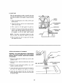
m. When backing
up the workpiece,
the blade may bind
in the kerf (cut) . . . this is usually caused by sawdust
clogging up the kerf. If this happens;
15
...........................
19
Of Machine
The band saw
work bench, in
band saw to tip
such as cutting
be bolted to the
6.
Tools
Band Saw/Sander
3.
5. Stability
for Power
I.
Insert a screwdriver
or wedge in the kerf..,
rotate
the wheels by hand while backing
up the workpiece.
The band saw should be positioned
so neither the operator nor a casual observer is forced to stand in line with
the blade. This band saw is intended
for indoor use only.
Eyes, Hands,
Face, Ears, Body
a.
Wear safety goggles that comply
with
ANS Z87.11968, and a face shield if operation
is dusty. Wear
ear plugs or muffs during extended
periods of operation. Do not wear gloves . . . roll long sleeves above
the elbow.
b.
Do not
hand.
Avoid
could
sanding
pieces
of
material
too
small
to hold
by
e.
belt.
Make sure the blade
Always
o.
Never operate the band saw with
the unused shaft end of the motor
Read and follow
of the band saw.
runs downward
toward
adjust
tension
correctly
h. When cutting a large piece of material,
supported
at table height.
more
4.
BEFORE
UAL.
firmly
against
the table.
j. Do not feed the material
too fast while
cutting.
Only feed the material
fa_t enough so that the blade
will cut. Keep fingers away from the blade.
on
front
GOGGLES
BE-
WHEN
OPER-
SAW
BLADE
IS INSTALLED
POINTING
DOWNWARD
TO
TABLE-BEFORE
OPERATING
ADJUST
MANUAL
MACHINE.
OPERATING
BLADE
TENSION.
BEARINGS
ARE
ALWAYS
PIECE
THIS
THE
TEETH
THE
BE SURE
THRUST
BLADE
GUIDES,
AND
PROPERLY
ADJUSTED
MACHINE-SEE
UPPER
BY NO MORE
MAC
GUIDE
THEN
1/4
OWNERS
MAN.
TO CLEAR
WORK-
INCH.
6. MINIMIZE
INJURY
POTENTIAL
OF CONTACTWITH
SAW
BLADE
OR
SANDING
BELT
BY KEEPING
FINGERS
A SAFE
DISTANCE
AWAY
7.
MAINTAIN
ALL
i, Hold the work
on
SAFETY
OWNER'S
WEAR
SAFETY
THIS
MACHINE.
WARD
HINE
than
make sure it is
cover
appearing
OWN
UNDERSTAND
3. BE POSITIVE
PROPERLY
for the blade or sand-
blade guides not
when cutting.
instructions
OPERATING
2. ALWAYS
ATING
5.
g. Always
adjust the upper
1/4" above your material
the
YOUR
AND
FORE
the table
ing belt being used.
protective
removed.
DANGER
FOR
1. READ
in the right direction.
Always adjust tracking
wheels
correctly
so that the blade does not run off the wheels.
f.
Never leave the band saw work area with the power
on before the machine
has come to a complete
stop,
or without
removing
and storing
the switch
key.
awkward
hand positions,
where a sudden slip
cause a hand to mow
into the blade or the
Never turn your band saw "ON"
before clearing the
table of a!l Objects
(tools,
scraps of wood,
etc.)
except for the workpiece
and related feed or support
devices for the operation
planned.
d.
n.
8. If any part of this band saw should break, bend, or fail
in any way or any electrical
component
fail to perform
properly,
or if any is missing, shut off power
switch,
remove
power supply
cord from power supply
and replace damaged
missing
and/or
failed
parts before
resuming operation.
9.
cut
Turn off the band saw, . . remove plug from power
source outlet
. . . remove
cover from
band saw.
must be bolted
securely
to a stand or
addition,
if there is any tendency
for the
over or move during
certain operations
long heavy boards. The band saw should
floor.
Location
7. Protection:
Use caution
when cutting off material
which
is irregular in cross section which could pinch the blade
before the cut is completed.
A piece of molding
for
example should lay flat on the table and no_ be permitted to rock while being cut.
8.
BE
CONTROL
TIMES--HOLD
ATTENTIVE
TING
SLOT.
END
OF
OF
FIRMLY
TO
SLOT
THIN
IN
THE
WORKPIECE
AGAINST
CUT-OFF
INSERT.
THE
AT
TABLE
PIECES
OR
JAMMING
HIT
IN
10. Think
Safety. Safety is a combination
of operator common sense and alertness at all times the band saw/sander
is operating.
additiona! safety instructions
for band saw/sander
WARNING:
THE 5" BAND
SAW PULLEY
2-1/2"
MOTOR
PULLEY
FURNISHED,
WILL
BLADE
AT APPROXIMATELY
900
RPM
FEET PER MINUTEI
WHEN
USED WITH A
MOTOR.
NEVER
INCREASE
THIS
GEROUS.
WARNING:
DO NOT ALLOW FAMILIARITY
(GAINED
FROM FREQUENT
USE OF YOUR BAND SAW) TO
BECOME COMMONPLACE. ALWAYS REMEMBER THAT
A CARELESS FRACTaON OF A SECOND IS SUFFICIENT TO iNFLICT
SEVERE iNJURY.
AND THE
RUN THE
(OR 2700
1725 RP_
SUBSTITUTE
THESE
PULLEYS
TO
SPEED BECAUSE
IT COULD BE DAN-
4
This machine
is designed
to
Do not use any motor
that
use a 1725
runs faster
RPM motor
than 1725
only.
RPM.
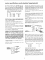
It is wired for operation
on 110-120
volts, 60 Hz., alternating
current.
IT
MUST
NOT BE CONVERTED
TO
OPERATE
ON 230 VOI.TS.
EVEN
THOUGH
SOME OF
THE RECOMMENDED
MOTORS ARE DUAL VOLTAGE.
THESE CRAFTSMAN
MOTORS HAVE BEEN
FOUND TO BE ACCEPTABLE
FOR USE ON
THIS TOOL.
HP
1/3
RPM
1725
VOLTS
110-120
CATALOG NO.
1250
1/2
1725
110-120
1254
1/2
1725
110-120
1255
This power tool is equipped
with a 3-conductor
cord and
grounding type plug which has a grounding
prong, approved
by Underwriters'
Laboratories
and the Canadian
Standards
Association.
The ground
conductor
has a green jacket
and
is attached to the tool housing at one end and to the ground
prong
This plug
requires
outlet as shown.
adapter
known
CAUTION: Do not use blower or washing machine motors
or any motor with an automatic reset overload protector
as their use may be hazardous.
This
machine
the operator
TO POWER SOURCE
must
from
be grounded
electric
while
OUTLET
in use to
plug at the other
a mating
3-conductor
end.
grounded
type
If the outlet
you are planning to use for this power tool is
of the two prong type
DO NOT REMOVE
OR ALTER
THE
GROUNDING
PRONG
IN ANY
MANNER.
Use an
It
CONNECTING
in the attachment
as shown
and always
connect
the
grounding
lug
to
ground.
is recommended
replace
THREE
that
the TWO prong
prong outlet.
An adapter
to 2-prong
you
have
outlet
with
a qualified
electrician
a properly
grounded
as shown below is available for connecting
plugs
receptacles.
The green grounding
lug extending
from the adapter must be connected
to a permanent
such as to a properly
grounded
outlet box.
ground
protect
shock,
Plug power cord into a 110-120V
properly
outlet
protected
by a 15-amp. time delay
fuse or circuit breaker.
grounded
type
or Circuit-Saver
If you are not sure that your outlet
is properly
have it checked by a qualified
electrician.
grounded,
WARNING: DO NOT PERMIT FINGERS TO TOUCH THE
TERMINALS
OF PLUGS WHEN INSTALLING
OR REMOVING
THE PLUG TO OR FROM THE OUTLET.
WARNING:
IF NOT PROPERLY
GROUNDED
THIS
POWER TOOL CAN INCUR THE POTENTIAL HAZARD
OF ELECTRICAL SHOCK. PARTICULARLY
WHEN USED
IN DAMP LOCATIONS IN PROXIMITY TO PLUMBING.
IF AN ELECTRICAL
SHOCK OCCURS THERE IS THE
POTENTIAL
OF A SECONDARY
HAZARD SUCH AS
YOUR HANDS CONTACTING
THE SAW BLADE.
If power cord is worn
it replaced immediately.
or cut,
or damaged
If your unit is for use on less than
that looks like below.
in any way, have
150 volts
it has a plug
NOTE: The adapter illustrated is for use only if you already
have a properly
grounded
2-prong
receptacle.
Adapter
is
not allowed
in Canada by the Canadian
Electrical
Code.
The use of any extension
cord will cause some toss of
power.
To keep this to a minimum
and to prevent
overheating
and motor burn-out,
use the table below to determine the minimum
wire size (A.W,G.)
extension
cord. Use
only 3 wire extension
cords which
type
plugs and 3-pate receptacles
plug.
Extension
Cord
Length
have 3-prong grounding
which
accept the tools
Wire
Up to 100 Ft.
3--PRONG
PLUG
PROPERLY
GROUNDED
/fl
UI
OUTLET_,_
/n
ul
<
GROUNDING
PRONG
CHECK
Size
A.W.G.
16
100-200
Ft.
14
200-400
Ft,
10
MOTOR
ROTATION
WARNING:
FOR YOUR
OWN SAFETY,
MAKE
PLUG IS NOT CONNECTED
TO POWER SOURCE
LET. WHEN CHANGING
MOTOR
ROTATION.
SURE
OUT-
The
motor
must
rotate
COUNTERCLOCKWISE
when
viewed
from the shaft end to which
you will mount
the
pulley.
(See page 11) If it does not, change the direction
according
to
the
instructions
furnished
with
the
motor.
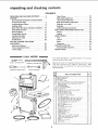
unpacking and checking contents
CONTENTS
UNPACKING
AND
ASSEMBLY
CHECKING
CONTENTS
.....
...........................
6
Mounting Band Saw/Sander on Recommended
Craftsman Floor Base ...................
7
Installing
Sawdust
8
Installing
Table
Motor
Pulley
Elbow .................
.......................
Belt Guard
Check Motor
Rotation
9
and Motor
Installation..
..................
Mounting
Motor
Attaching
Belt Guards ...................
12
The Blade ....................
Adjusting
The Table ....................
13
15
19
Switch ........................
GETTING
TO KNOW
SAW/SANDER
YOUR
20
BAND
.........................
Adjustment
Diagrams
22
...................
Tension
Adjustment
Tension
Scales ........................
-
Installing Sanding Attachment .............
BASIC BAND SAW/SANDER OPERATION
Sawing .............................
Sanding ............................
MAINTENANCE ........................
Tires ..............................
General
...........................
Motor .............................
Lubrication ..........................
TROUBLE SHOOTING
...................
Recommended Accessories................
REPAIR PARTS ........................
10
11
......................
Installing
On-Off
Table Tilting .........................
Blade Guide Adjustment .................
Lateral Guide Adjustment ................
Blade Thrust Bearing Adjustment ...........
Guide Bar Lock Knob ..................
Guide Bar ...........................
7
22
Knob ................
TOOLS
22
22
NEEDED
--
-
22
22
22
22
22
23
23
25
25
25
26
26
26
26
26
27
27
28
......
Your Band Saw/Sander
(w_thout rno[or or floor
s shipped
basel
comolete
m one carton
Separate all oarts from packing
materials
and check each
i[ern w_th
Ilustratlon
and "Table of Loose Parts." Make
certain all items
paekinq material.
MEDIUM
SCREWDRIVER
3!8-tNCH
are accounted
\
I
1
2
3
4
5
6
1
8
9
TABLE
I/2-I
n. Sanding
I/4-I
n. Band-Saw
Sawdust
OF LOOSE
PARTS
any
Qty.
Two
Bags
I
Blade
...............
I
1
containing
the
following
Screw
Bcrew
Wrench,
Wrench,
1/8"
5/32"
Set
Screw
Wrench,
3/16"
Washer,
1 I/8"
.
ttems:
............
. ...........
. ...........
t
...........
2
diameter
Locknut
1
1
.................
I
Pan-Hd.
Mach,
Screw,
Self
Tap,
10-32x3i8",
Pan
aaeh,
Screw,
Self
Tap,
B-32x1/4"
Rd.
Soc-Hd.
Setscrew,
Flat
Flat
Hd. Mach_ Screw,
Hex
Nut,
6-32
Knurled
Rubber
Hd.
Clamp
Pt,, 5/16-t8x3/8"
6-32x7/16".
........
....................
Gasket
Mach.
Platen
Inaetl
Screw
..............
Tenspon
Switch
Key
I
I
I
..................
I
for
sawing)
sanding)
................
....................
1
1
I
{nartowalot,
Knob
1
.
1
..............
Table
Insert
(w_de slot,
for
Tilt
Lock
Handle
(Wrench)
Spacer
Blade
....
2
.
1
1
A ignmen
t Plate
...................
Motor
Pulley,
2-I/2".
...............
Sanding
.
. .
1
.....................
(str,ps)
.
. .
Lockwasher,
No. 6 ..............
Pointer
.....................
Tube
Table
2
Belt
Set
Set
Spht
Tilt
1
1
, 1
, 1
E I bow
Trunmon
8/
discarding
Bas_e Saw Assembly
................
Owner's Manual.
Saw Table ......................
1/2x 52-1n, V-Belt ..................
Carton containing
Belt Guard, Belt-Guard
Support,
Support
Bracket,
three Clips and three SelfTapping
Screws
...................
Flat
7
before
WRENCH
Key
N0.
1
for
.......
........
1
1
1
1
!
2
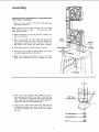
assemb!y
MOUNTING BAND SAW/SANDER
CRAFTSMAN FLOOR BASE
ON RECOMMENDED
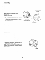
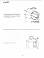
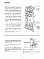
1. Unscrew
the four knobs
and remove the cover.
front
NOTE:
Check
the
bolts
saw. Make sure they
loose during
shipment.
on the
which
2. Place the band saw on the
align mounting
holes.
3.
hold
are tight
the
of the band
feet
. , . they
base, position
to
may
saw
the band
have come
as shown,
and
LEFT
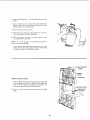
Find one 5/16"-18
x 3" Hex. Head bolt, two 5/16"18 x 2" Hex. Head bolt, three nuts, flat washers and
Iockwashers
furnished
with base. Find one 1-1/8'" dia.
flat
washer
from
the stiffner
among
the
Position
5.
Insert the two 2" bolts through
the holes
foot and through the holes in the stiffner.
6.
Place
a
bolts
from
washer,
underneath.
with
parts
4.
flat
furnished
loose
Iockwasher,
Do
furnished.
CHECK BOLTS
FOR
base as shown.
and
not
FOOT_
in the
a nut
tighten
on
the
right
these
nuts.
STIFFNER
3" BOLT
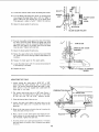
7. Place the
1-1/8"
diameter
flat
washer on the 3"
bolt and insert the bolt in the hole in the left foot.
Place a flat washer, a Iockwasher,
and a nut
from underneath
and tighten
the nut. Now
other two nuts which you installed before.
on the bolt
tighten
the
8. Find two Hex. Head screws 7/16"
long, and two nuts
furnished
with
base, Insert these screws thru the top
of the base and stiffner
and screw on the nuts. Tighten
the nuts.
I
F LATWASH
ER -.-------_
@
LOCKWASHER
NUT
7
b
assembly
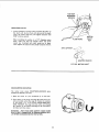
INSTALLING
SELF-THREADING
SCREW
SAWDUST ELBOW
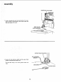
1. Find the sawdust elbow, the clamp, the strip of rubber
gasket, and two 10-32 x 3/8" self-threading screws
among the loose parts.
The holes for attaching
the clamp are not threaded,
but
the screws are "self-threading"
and will cut a thread as
they are screwed in.
2. Screw both of the self-threading
cut the threads and then remove
screws into
them.
CLAMP
/
the holes to
SAWDUST
ELBOW
3. Place the elbow in the opening, and attach the clamp
with the two screws.
RUBBER GASKET
4.
\
Peel off the protective
covering from the rubber gasket
and stick it around
the clamp. Make sure it extends
a little beyond
each end of the clamp.
The
out.
gasket
will
help to
For the most
efficient
Craftsman
Home-n-Shop
prevent
sawdust
from
\
leaking
removal
of sawdust, attach a
Vac to the sawdust
elbow.
8
TABLE TRUNNION
INSTALLING
TABLE
NION PiN
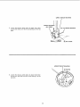
Remove
the protective
oil
Use any ordinary
household
that is applied
to the table.
type grease and spot remover.
CAUTION:
Never use gasoline, naptha or similar highly
volatile solvents.
Apply
a coat of automobile
wax to the table.
TABLE
LOCK BOLT
\
\
1. Place the table
on the band saw so that
pins and the table
trunnion.
2.
bolt
the two
go through
Find the 1-I/8"
dia. flat washer, a sleeve
the trunnion
lock nut and the table lock
among
3,
lock
the
trunnion
the slot
in the
11/16"
handle
long,
from
_NUT
loose parts,
Hold the head of the table lock bolt inside the band saw
with your left hand and put the 1-1/8" dia. flat washer,
the sleeve, and the handle on the bolt.
4. Screw the nut on the bolt and tighten it with
while the table is in a horizontal
position.
the handle
lllJ,;/
TABLE
LOCK
BOLT
TABLE
LOCK
HANDLE
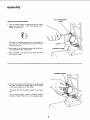
assemb|y
THREAD CUTTING
SCREWS
MOTOR
PULLEY
I NSTA L LAT! ON
MOUNTING
1. Place
facing
BELT
BELT
the
motor
GUARD
AND
MOTOR
GUARD
on
your
workbench
with
the
shaft
you.
If you are using a double
shaft must be facing you.
shaft
motor,
the 5/8"
dia.
BELT GUARD
SU PPORT BRACKET
BELT GUARD
SUPPORT
2. Attach
screws,
guard
support
furnished
with
to the bracket
the guard.
with
the two
NOTE: The holes in the bracket are not threaded, but the
screws are "thread cutting screws" and will cut a thread as
they are tightened.
SCREWS
10
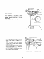
s/32 iNCH
I
_
SETSCREW
/
WRENC.
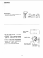
MOUNTING
I.
Loosen
PULLEY
setscrew
in motor
pulley
the shaft with the hub flush
insert
the motor
shaft key
5/32"
setscrew wrench.
and place the pulley on
with the end of the shaft,
and tighten setscrew with
_J___'_"_
_-
When installing
the pulley
on a 1/2"
diameter motor
shaft,
make sure that
the adapter
sleeve and 3/16"
square
key furnished
with
your
motor
are in place.
Then tighten the setscrew with a 5/32"
setscrew wrench.
3/16x
MOTOR
FLUSH
HERE
SHAFT
KEY
3/16 KEY ....,.
L
\
ADAPTER
SLEEVE
112" DIAo MOTOR SHAFT
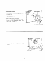
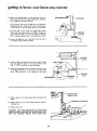
CHECK MOTOR
The
motor
viewed from
I.
Place
the
ROTATION
must
rotate
the PULLEY
motor
on
COUNTERCLOCKWISE
end.
your
workbench
or on the
when
floor.
2. Stand clear of the motor
and plug the cord into a properly grounded
outlet
(See page 4). Notice the rotation
of the pulley.
If it is not turning
COUNTERCLOCKWISE,
REMOVE
the plug from the outlet,
and change
the rotation
of the motor
according
to the instructions
furnished
with the motor.
WARNING:
FOR YOUR OWN SAFETY, MAKE SURE
PLUG IS NOT CONNECTED TO POWER SOURCE OUTLET WHEN CHANGING MOTOR ROTATION.
11
assembly
MOUNTING
MOTOR
1. Find four 5/16"-18x 1" carriage bolts, flat washers,lockwashersand nuts supplied with base.
MOTOR MOUNT
BRACKET
2, Insert bolts through holes marked "X"
motor mount bracket.
GUARD
:
c:_
L--J_ _-_c:_
from behind
3. Attach motor..,
place a flat washer and a Iockwasher
on each holt . . . screw on nuts but DON'T TIGHTEN
them.
4. Loosen the two BELT
-[
SUPPORT
BELT GUARD
SUPPORT SCREWS _,_
SCREWS.
5. Loosen the two MOTOR BASE CLAMP SCREWS and
rotate the motor so that the ventilation holes are
facing downward ... tighten the screws.
VENTILATION
HOLES
FACING DOWNWARD
6. Tighten the BELT GUARD SUPPORT SCREWS.
12
MOTOR BASE
CLAMP SC
(BOTH ENDS)
ATTACHING
BELT
GUARDS
1. Remove the pulley from the band saw, using the 5/32"
setscrew wrench to loosen the screw. Be careful not to
lose the shaft key.
Attach
nished
NOTE:
the belt guard
with the guard.
The support
support
bracket
is not
with
the three
screws fur-
required.
The holes for attaching
the support
but the screws
are "self-threading"
thread
as they
are screwed
in.
are not threaded,
and will cut a
SELF-THREADING
FLUSH
/
2.
Replace the pulley
the shaft.
with
the
hub
flush
with
the end of
13
HERE
SCREW
assembty
LONG
POINTED
3. Install
long
three clips
tabs
4. Insert one
that it will
on the belt guard 90 ° apart with
pointing
AWAY
from
the
round
looped end of belt all the way
be below motor pulley.
into
TAB
THIS
WAY
\
the
opening.
guard
so
/
OPEN
END
/
_'_--SPRING
_"_
5. Snap the guard into
position
as shown,
14
CLIPS
(SET 90 ° APART)
6. Look down
pulley.
7. Insert
the
into guard..,
belt
guard, and out
band saw pulley
into
pull belt
the
open
the round
by rotating
8. Snap the belt guard
into
end
opening,
pulley.
upwards
of the
NOTE:
It
is only
does not slip
while
motor
second
belt
Place belt onto
the
position,
9. Move the motor sideways so that the belt
ter of the opening in the top of the base.
10, PUSH downward
and tighten motor
onto
on motor
bolt nuts.
necessary
to
apply
to tension
is in the cen-
tension
the
to
belt
belt so that
it
running.
If you cannot obtain sufficient
tension with the motor
pushed all the way down, remove the four motor bolts
and insert them in the LOWE R set of holes.
BLADE TENSION
KNOB
.TENSION
STUD
iNSTALLING
1. Find the
a dab of
screw it
turns, just
2. Loosen
guard.
POINTER
THE BLADE
blade tension knob among the loose parts. Put
grease or vaseline on the end of the knob and
on the tension
stud. Screw it on only a few
enough to start moving the pointer.
the two
mounting
screws and remove
the
-,-BLADE
GUARD
MOUNTING
blade
15
assembly
GUIDE
BAR LOCK
KNOB
GUIDE
BAR
3. Loosen the guide bar lock knob and position the upper
guide assembly
approximately
three inches above the
table and tighten
the knob,
UPPER
BLADE
UPPER
1/8"
..__
THRUST
SETSCREW
WR ENCH''_
!
BEARING
!
4. Loosen the two setscrews which lock the upper blade
guides and separate them about 1/8".
Do that
table,
same
thing
to
the
lower
guides
beneath
the
SETSCR
EWS
BLADE
16
GUIDE
UPPER THRUST BEARING
THRUST
ADJ.
5. Loosen the setscrew which locks the upper thrust bearing and turn knob until the thrust bearing is all the way
back.
BEARING
KNOB
1/8"
/
SETSCREW
BLADE
LOWER THRUST
WRENCH
GUIDE
BEARING
SETSCREW
6.
Loosen
the
ing and turn
way back.
setscrew
the
knob
which
until
locks
the
the thrust
lower thrust
bearing
bear-
)
is all the
17
assembly
7. Carefully
uncoil
the blade,
holding it at arms length.
8. Place the blade over the wheels with the teeth pointing
downwards.
Make sure the blade is between
the blade
guides and
is in the center
of the rubber
TRACKING
ADJUSTMENT
SCREW
tires.
9. Screw down the tension knob until the
to 1/4. This will put sufficient
tension
which is 114" wide.
pointer
points
on the blade
10. Turn the upper wheel by hand a few times and notice
if the blade remains in the approx, center of the tire on
the top wheel.
If the blade
moves away
while you are turning
properly.
from
the center
it. the blade
of the wheel
is not TRACKING
The top wheel shaft
to be tilted
so that
is hinged which allows the wheel
the blade can be TRACKED.
By
turning the
be tilted.
tracking
adjustment
If the blade
moves toward
the
screw,
front
the
wheel will
of the
band saw:
a. Turn the tracking adjustment
screw clockwise about
1/4 of a turn, as though
you were tightening
it.
If the
blade moves toward
the
back
of the
band
BLADE
CENTERED
ON TIRES
OF BOTH
WHEELS
saw:
a. Turn the tracking adjustment
screw counterclockwise about 1/4 of a turn as though you were loosenmg it.
Turn the screw
the approximate
The thrust
will rotate
just enough to cause the blade to run in
center of the tire,
bearings support the blade from the rear and
when the blade is pushed against them while
you are cutting.
ings should step
As soon as you
rotating.
stop cutting,
11. Turn
the thrust
bearing adjustment
thrust
bearing
moves toward
the
touches
it.
knob
blade
the
bear-
THRUST BEARIN(
so that the
and almost
12. Turn the upper wheel by hand so that the blade moves
downward,
move the bearing until it barely touches the
r
blade and starts to rotate. Now move the bearing back
slightly,
until
it stops rotating.
Tighten
the thrust
bearing setscrew.
13, Adjust
the lower thrust
bearing the same way.
18
THRUST BEARING
ADJ. KNOB
GL
14.
Loosen
the setscrew
which
locks the
blade guide holder.
15. Turn the blade guide adjustment
knob, so that the guides
move toward the blade. Move them until the "ledge"
is
APPROX.
1/32"'
BLADE
about 1/32" from
the deepest part of the blade teeth.
This deep part is called a "gullet".
Tighten the setscrew.
16. Adjust
the lower
GUIDE
KNOB
guides the same way.
SETSCREW
BLADE GUIDE HOLDER
17. Press the two guides evenly against the sides of the blade,
but don't pinch the blade. Release the guides and rotate
the upper wheel a little bit, moving the blade downward.
Make sure one guide is not farther
away from the blade
than the other. Tighten
both setscrews_
18. Adjust
the lower
Y
li II
*'-"--
SAW BLADE
_UPPER
BLADE
GUIDE
guides the same way.
19,
Rotate the
the guides
necessary.
upper wheel a few times by hand, and check
and thrust
bearings. Make readjustments
if
20.
Replace
21.
Locate the table insert with
in the opening in the table.
22.
Replace the cover.
the
blade
guard
on the
upper
guides.
the narrow
slot
and place it
_'_TABLE
ALIGNMENT
SCREW
ADJUSTING
THE
TABLE
1. Locate
among
the
loose parts a 5/16"-18"
x 3/8"
socket
head flat
point
setscrew
and a knurled
head
screw. The knurled head screw keeps the table in alignment. Screw
it into the tapped
hole underneath
the
front
edge of the table.
2. The
socket
partially
on the
head
into
left
screw
acts
as a
90 °
stop.
Screw
COMBiNATiON
DE
the tapped
hole in the top of the table
side.
Use the 5/32"
setscrew
wrench.
5/32"'
3. Raise the blade guides all the way up.
4. Loosen the table lock slightly
and push down on the
left side of the table until it touches the frame of the
band saw.
5. Screw
frame,
in the stop screw and notice
the table will start to tilt.
6. Place a square
tinue to screw
with
7. Find
the
pointer
as it touches
the
on the table against the blade and conin the stop screw until the table is square
the blade. Tighten
long and attach
the screw.
that
the table lock.
and a pan head screw
the pointer.
8-32 x I/4
SQUARE
it
inches
Set at 0 degrees and tighten
19
SETSCREW
WRENCH
assembly
ON-OFF SW|TCH
WARNING:
DON'T CONNECT POWER CORD
TO ELECTRICAL
OUTLET IN YOUR SHOP
UNTIL YOU ARE SURE THAT MOTOR ROTATION
IS CORRECT. (SEEPAGE 11).
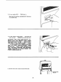
The On-Off Switch has a locking feature.TH|S SHOULD
PREVENT UNAUTHORIZED
AN D POSSIBLY HAZARDOUS USE BY CHILDREN AND OTHERS.
1. Insert key into switch.
NOTE:
Key is made of yellow plastic
©
2. To turn machine on, insert finger under switch lever
and pull end of switch out.
2O
3. To turn
machine
OFF
. ..
PUSH
lever in.
Never leave the machine unattended
to a complete
4.
until
it has come
stop.
To lock switch
in OFF
with
. . . REMOVE
one hand
position
. ..
hold switch
key with
other
IN
hand.
WARNING:
FOR YOUR OWN SAFETY, ALWAYS LOCK THE SWITCH
"OFF"
WHEN
MACHINE
iS NOT IN USE ... REMOVE KEY
AND KEEP IT IN A SAFE PLACE . . . ALSO
• . . IN THE EVENT OF A POWER FAILURE
(ALL OF YOUR
LIGHTS GO OUT) TURN
SWITCH OFF... LOCK II"AND REMOVE THE
KEY. THIS WiLL PREVENT THE MACHINE
FROM STARTING
UP AGAIN
WHEN THE
POWER COMES BACK ON.
5. Connect motor cord to outlet on back of band saw.
)RD
OUTLET
21
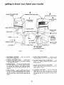
getting to know your band saw/sander
2
COVER RETAiNiNG
(4-Used)
8
KNOB
GUIDE BAR LOCK KNOB
/---TENSION
ADJUSTING
KNOB-_
3
1
BLADE TENSION
SCALE
ADJUSTMENT
DIAGRAMS
ON-OFF SWITCH "_
BLADE
GUARD
MOTOR CORD
OUTLET
!
9
7
GUIDE
BAR
THRUST
BEARING
ADJ. KNOB
(Lower Knob
Not Shown)
TILT
LOCK
HANDLE
SAW PULLEY
BLADE GUIDE
ADJ. KNOB
(Lower Knob Not Shown)
BA CK
FRONT
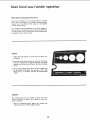
1. ADJUSTMENT DIAGRAMS . . . Helo you to become
familiar with the adjustments.
5=
2. TENSION
ADJUSTMENT
KNOB . . . Tightening
the
knob will increase the tension on the blade. Loosening
it will decrease the tension.
6.
BLADE GUIDE ADJUSTMENT
. .. Turning the knob
moves the guides in ol out for various widths of blades.
LATERAL
BLADE
GUIDE
guides can be adjusted
by the setscrews.
3. TENSION SCALES...
The fractional markings indicate
the correct blade tension for various widths of blades.
For example, when installing a 1/4" wide blade, tighten
the tension knob until the pointer is pointing to the 1/4
marking.
7,
BLADE
THRUST
BEARING
ing the knob moves the
various widths of blades.
4. TABLE TILTING . .. Loosen the table lock handle, tilt
the table to the desired angle and tighten the lock handle.
To return the table to the 90 ° position, tilt it until the
90 ° stop screw rests on the frame, then tighten the lock
handle.
8°
GUIDE
should
ADJUSTMENT
sideways
. . . The
and locked
ADJUSTMENT...
thrust
bearings
in position
Turn*
in or out
BAR LOCK KNOB.
- . The upper blade guides
not be more than 1/4" above your workpiece
while cutting.
Always adjust the guides before turning
the band saw and lock the guide bar by tightening
knob.
22
for
on
the
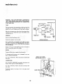
9. GUIDE
BAR
When the upper guides are raised or lowered,
they must
not deflect the blade sideways. This means that the guide
bar must be parallel
to the blade, or square with the
table.
1.
Remove the blade guard,
guide assembly.
2.
Lower
1-3/4"
3. Hold
4.
cover,
the guide bar until
from the table.
a square
on
the
the table
blade,
/_"_"_--__
and the upper
end is approximately
against
SCREW
the
guide
_ IIlIIA\ L//_Y/ /
WRENCH
bar.
If the bar is not square with the table, loosen the four
screws in the guide bar support.
Use the 3/16"
setscrew wrench.
To reach the lower left screw, it will
be
necessary
to
tilt
the
upper
wheel
outward.
NOTE:
The holes in the guide bar support
are larger
than the screws. This allows the support
to be moved.
5. Move the guide bar until
then tighten the screws.
iNSTALLING
SANDING
it is square with
the
table,
ATTACHMENT
WARNING:
FOR YOUR
OWN SAFETY,
TURN
SWITCH
"OFF"
AND ALWAYS
REMOVE
PLUG FROM POWER
SOURCE
OUTLET
BEFORE
INSTALLING
SANDING
ATTACHMENT.
1. Remove the blade
alignment
screw.
guard,
the table
2. Remove the cover,
the blade.
release the blade tension
5. Loosen
the
setscrew that
the
bearing
two
and the table
and remove
HEX.
3. Remove
the upper blade guide
wrench to remove the screw.
4. Loosen the
and move
insert,
apart
ASSEMBLY
Use a 3/8"
locks the lower thrust bearing,
as far
back as it will
go.
setscrews
guides, Spread them
is inside the holder.
assembly.
that
so that
lock
the
lower
HD. SCREW
blade
the end of each guide
23
getting to know your band saw/sander
6. Attach the sanding platen to the guide bar with the
same screw that held the upper blade guide assembly.
Do not tighten the screw at this time.
On the smooth side of the sanding belt, you will find a
"directional arrow". The belt n_ust run in the direction
of this arrow so that the splice does not come apart.
7. Place the belt on the wheels and tighten the tension
knob until the pointer points to SAND. Rotate the
upper wheel by hand a few times to make sure that the
belt is tracking properly and is not rubbing the guides.
PLATEN
8. Loosen the guide bar lock knob and lower the end of
the sanding platen below the table.
-'k
SANDING
PLATEN
CENTER OF S
9. Locate among the loose parts, the insert with the wide
slot, the alignment
plate,
a flat head machine screw
6-32 x 7/16",
a small hex nut and Iockwasher.
TABLE IN
10. Attach the alignment
plate to the insert so that the end
of the alignment
plate is in the center of the slot in the
insert, Place the insert
in the opening
in the table.
ALIGNMENT
LOC KWASH ER
\
,/_
PLAT E
-,_----SANDING
BELT
AND PLATEN
11. Hold a square
platen.
on the table
against the
sanding
belt
and
platen
to
)MBINATION
12. Tighten the hex.
the guide bar.
head
screw which
holds the
13. Replace the cover.
WARNING:
FOR YOUR OWN SAFETY. DO NOT SAND
IRON OR STEEL BECAUSE THE SPARKS COULD IGNITE THE SAWDUST
INSIDE
YOUR BAND SAW.
24
SQUARE
basic band sac/sander
BASIC BAND SAW/SANDER
operation
OPERATION
A band saw is basically a "curve cutting"
machine.
It differs
from a saw in two respects. It is capable of cutting thicker
material
and it cuts faster.
Unlike a saw, it is not capable
of doing
Your
inside cutting.
Craftsman
Band
Saw/Sander
the usual band saw operations,
a sander as well. You can finish
and plastics
and non-ferrous
is not
only
capable
of
but it can be converted
into
wood, certain compositions
metals.
SAWING
1. Adjust the upper
workpiece.
guides not
more than 1/4"
above your
2. Use both hands while feeding the work into the blade.
Hold the workpiece
firmly
against the table. Use gentle
pressure, and do not force the work, but allow the blade
to cut.
3. The smallest
diameter
that
can be cut out
is determined
by the width
of the blade. For example,
a 1/4"
wide
blade will cut a minimum
diameter
of approximately
1-I/2".
SANDING
The
with
some
sand
your
1. Press the workpiece
gently against the sanding
and keep moving it until the edge is smooth.
belt,
scraps
actual
sanding
belt
of wood
workpiece.
cuts
first
very
before
rapidly.
you
Practice
attempt
to
25
maintenance
WARNING:
FOR YOUR OWN SAFETY,
TURN :SWITCH
"OFF"
AND
REMOVE
PLUG FROM POWER SOURCE
OUTLET
BEFORE
MAINTAINING
OR LUBRICATING
YOUR
BAND SAW.
MOTOR
ON-OF F SWITCH
OUTLET
[
I
TIRES
Pitch
and sawdust
that
accumulate
on the tires
should
be
removed with a stiff brush or scraped off with a piece of
wood. De not use a sharp knife or any kind of solvent.
When the tires become
replacing the tires,
not glue them on.
worn
stretch
they should
them
around
be replaced.
the wheels
When
but do
[
|GREEN
GREEN]
GENERAL
GROUND
Keep your
Remove
Band Saw/Sander
the sawdust
from
clean.
m
the inside,
WIRING
DIAGRAM
Do not allow pitch to accumulate
on the table, the insert,
the guides or the thrust bearings, Clean them with CraftsTan Gum and Pitch Remover. CAUTION:
Do not immerse
the thrust bearings.
Apply a thin coat of automobile-type
wax
that the wood slides easily while cutting,
on the table
so
MOTOR
Frequently
blow out any sawdust
from
If the power cord is worn or cut,
have it replaced immediately.
For motor
the motor.
maintenance,
follow
the motor.
or damaged
instructions
in any way,
furnished
WHEEL NOT SHOWN
FOR PICTURE CLARITY
with
LUBRICATION
All of the BALL
BEARINGS
are packed with
factory.
They require no further
lubrication.
For motor
the motor.
Periodically
guide rods.
lubrication,
apply
a few
follow
drops
instructions
Of oil
to
grease at the
furnished
the upper
with
wheel
GUIDE RODS
26
m
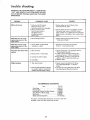
trouble
shooting
WARNING: FOR YOUR OWN SAFETY, TURN SWITCH
"OFF"
AND REMOVE PLUG FROM POWER SOURCE
OUTLET BEFORE TROUBLE SHOOTING YOUR BAND
SAW/SANDER,
PROBABLE CAUSE
TROUBLE
Motor
will not run.
1.
Defective
Defective
On-Off
switch
REMEDY
switch.
cord.
1. Replace defective
Band Saw/Sander
Defective switch box receptacle,
2. Motor protector
open,
(only if your motor is
equipped with an
overload protector).
Other cause.
Blade does not run in the
approximate
center of the
parts before
again.
using
2. Consult Sears Service. Any attempt to repair
this motor may create a HAZARD
unless
repair is done by a qualified
service technician,
Repair service is available at your nearest Sears
Store.
1. Not tracking
properly.
1. Adjust tracking, see Assembly
"Installing
the Blade."
Blade does not,run
in the
approximate
center of the
lower wheel,
1. Lower wheel
correctly
on
not positioned
shaft.
1, Reposition
the wheel, see Assembly
Section,
"Installing
the Blade."
Band Saw slows down
1. Belt too loose.
upper
Section,
wheel.
when
1, Adjust belt tension, see Assembly
Section,
"Attaching
Belt Guards.'"
2. Tighten
motor base clamp screws. See
Assembly Section, "Motor
Installation".
3. Stop feeding, and back up the material
slightly, until the band saw speeds up.
4. Replace blade.
cutting,
2. Motor
pivots
3. Cutting
4.
Blades breaking.
in motor
base.
too small a radius.
Dull blade.
1. Too
much tension,
1. Adjust tension. See Getting To Know
Your Band Saw/Sander,
"3 Tension
Scales."
2. Kink in blade caused by cutting
too small a radius or turning the
material
too fast when
2. Use correct cutting technique.
See Basic
Band Saw/Sander
Operation
Section.
cutting.
RECOMMENDED
ACCESSORIES
item
Floor
Cat. No.
Base ....................
9-22213
Miter Gauge ...................
Hold-Down
Clamp For Miter Gauge ....
Stop-Rods
For Miter Gauge .........
Rip Fence .....................
Blades and Sanding Belts ...........
The
above
available
recommended
at the time
accessories
this manual
27
9-29929
9-29928
9-29924
9-23432
See Catalog
are current
was printed.
and were
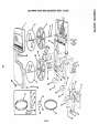
CRAFTSMAN
12-INCH
BAND SAW/SANDER,
MODEL
113.24201
8
ia
2
4
SEE FIGURE
FOR
EXPLODED
VIEW
14
\'
10
oo
3fi
40
\
39
38
2
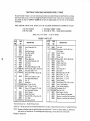
CRAFTSMAN
12-INCH
BAND SAW/SANDER,
MODEL
113.24201
All parts illustrated
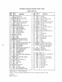
in Figures 1 and 2 and listed under part numbers may be ordered through any Sears Retail Store or Catalog
Order House. Order parts by mail from the Catalog Order House that serves the territory
in which you live. In several instances,
part numbers
are listed for COMPLETE
ASSEMBLIES.
All parts are shipped prepaid
within
the limits of the Continental
United States.
WHEN
ORDERING
REPAIR
PARTS,
ALWAYS
GIVE
1. THE PART NUMBER
2. THE PART NAME
THE
order
by Part
FIGURE
t_
cD
PART
NO.
1
2
3
4
5
6
7
8
9
10
11
12
13
!4
69069
41815
38524
37158
41711
STD315228
69028
41812
60256
60251
38884
STD601105
30789
STD503105
15
38450
16
17
18
18
19
60265
6O252
STD304430
STD304520
30646
20
21
22
23
24
60254
60253
425338
69052
STD541031
*Standard
tStock
Hardware
Item -
NOTE:
• Supplied
I
Frame with
Trim
Washer, Spring
Bearing, Ball
Wheel, Upper Drive
Ring Internal
Retaining
Key, Switch
Bearing, Ball
1-3/8
Ring, Internal
Retaining 1-11/16
*Screw Type 23, 10-32 x 1/2, Pan Hd.
Key, Square 3/16 x 1-1/4
*Screw, Set, 5/16-18 x 1/2, Soc. Hd.,
Cup Pt.
tPutley,
1/2 V Groove, 5" x 5/8
Bore, Keyed with Set Screw
Clip, "S"
Guard, Belt
otBett,
V Type, 1/2 x 43
fBelt "V" Type, 1/2 x 52
tPutley,
1/2 V Groove, 2-1/2"
x 5/8
Bore, Keyed with Set Screw
Bracket, Support
Support,
Belt Guard
*Screw, 5116-18 x I, Sems, Hex, Hd.
Foot, Right
*Nut, Square, 5/16-18
May Be Purchased
May be secured
through
Only.
AS SHOWN
ON THE
LIST:
not
by
Key
Number
LIST
PART
NO.
25
26
69053
STD522503
27
28
29
30
31
32
33
34
35
36
37
38
39
40
41
42
43
44
45
46
47
69023
65013
69004
STD601103
69078
69059
69058
69025
69006
69060
60272
37887
60096
37911
69062
133427
69063
69005
STD551t06
STD54t006
69037
69079
69081
69083
DESCRIPTION
Foot, Left
*Screw Mach., 1/4-20
Hd., Slotted.
Spacer, Bearing
Elbow
Clamp,
*Screw,
Gasket,
Wheel,
Shaft,
Lens
Tube
Mach., 10-32
Foam
Lower Drive
Lower Wheel
x 3/8,
Truss
x 3/8,
Pan Hd.
Knob Assembly
I"
Stud, Cover
tBlade, Band Saw, 1/4 x B0
tWrench,
Hex., "L",
1/8
1Wrench, Hex., "L", 5/32
tWrenchr
Hex., "L", 3/16
Platen, Sanding
*Screw, Mach., 6-32 x 7/16,
Flat
Hd.
Insert, Table (Sanding)
Plate, Sanding Alignment
*Lockwasher,
No. 6
*Nut, Hex., 6-32
tBelt, Sanding, 1/2 x 80
Owner's Manual (Not Illustrated)
Bag Asm. Loose Parts (Not Illustrated)
Bag Asm. Loose Parts (Not tlt6strated)
Locally.
the Hardware
Department
Shipping and handling
charges for standard hardware
these items by mail uneconomical.
To avoid shipping
In Canada
-
KEY
NO.
Screw, Self-Locking
Ring, Retaining 5/8
Item -
Number
1 PARTS
DESCRIPTION
Cover,
Tire
INFORMATION
3. THE MODEL NUMBER 113.24201
4. THE NAME OF ITEM - 12-INCH BAND SAW/SANDER
Always
KEY
NO.
FOLLOWING
of most Sears or Simpsons-Sears
Retail
items (identified
by *) such as nuts, screws,
and handling charges, you may obtain most
Stores or Catalog
Order
Houses.
washers, etc., make buying
of these locally.
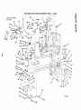
CRAFTSMAN
12-tNCH
BAND SAW/SANDER.
MODEL
113.24201
B
"0
Q
a_
Q
8
I
21
20
19 14
FIGURE
2
CRAFTSMAN
12-INCH
BAND SAW/SANDER,
FIGURE
PART
NO.
69017
STD551050
STD5510t2
69073
9423400
69031
69033
STD502502
69042
69046
69047
69O48
69049
69021
STD 541037
69077
69072
STD551037
STD600802
38724
69070
453068
69029
38876
69068
41426
69022
69019
69018
273229
69016
STD600602
69066
STD533725
69057
38794
69074
STD571203
69065
69024
*Standard
tStock
Order
Pin, Pointer Pivot
Washer, Plain, 1/2 x 1-1/4 × 1/8,
Washer, Plain, 17/64 x 1/2 x 1/16
Scale, Tension
"Screw, Type 23, 1/4-20 x 3/8 Pan Hd.
Knob Assy., Tension Adjustment
Knob Assy., 1-1/2"
*Screw, Set, J/4-20 x t/4 Soe. Hd., FL Pt.
Sleeve, Thrust Bearing
Screw, Thrust Adjustment
Washer, 1/4 x !-13/32
x 1/t0
Knob, Lower Guide
Screw, Guide Adjustment
Pin, Trunnion
Nut, Hex. 3/8-16
Spacer
Wrench
Washer, Plain, 3/8 x 1-!/8
Guide Assy., Fulcrum (includes Kmi No. 241
Bracket, Upper '¢2,1eel Support
Rod, Upper Wheel Guide
Spring, Wheel Tension
Spring, Pointer
Screw. Tapping,
1/4-20 x 1/2, Hex Washer Hd.
Pointer
*screw, Type 23, 6-32 x 1/4, Pan Hd.
Scale Tilt
x 2-1/2
Pin, Rol! 1/8 x 5/16
Insert Table
60190
Pin, Lower Guide Support
Screw, Self-Locking,
5/16-18
Hardware
Item
Item
- May Be Purchased
.- May t_ secured
Houses.
oSupplied
x 7/64
Bumper, Upper Wheel
Pin Roll 1/4 x 3/4
Bolt, Carriage, 3/8-16
Trunnion
Screw, Knurled
Table
in Canada
only.
through
42
43
44
45
46
47
48
49
5O
51
52
53
54
55
56
57
"Screw, Type 23, 8-32 x 1/4, Pan Hd.
Pointer, Tilt
Frame Ass,/., W/Trim (Incl, Key Nos. 14 & 40)
*screw, 5/16-18 x 3/4, Scms. Hex. Hd.
113.24201
2 PARTS LIST
KEY
NO.
DESCRIPTION
MODEL
58
59
60
61
62
63
64
65
PART
NO.
69039
69045
STD551031
38825
STD502505
STD522505
STD315505
69038
STD522507
STD551t25
69041
STD601103
69044
69043
69035
216278
69036
69034
69012
37393
STD551225
STD522512
STD372252
69014
66
67
STD551208
STD510802
69
70
71
72
73
74
75
76
77
78
79
80
69066
STD600803
69009
60287
447845
69010
60257
69082
69027
71046
69026
37875
DESCRIPTION
Guide, 8tade
Guide, Lower Blade
Washer, Plain, 5/16 × 9/16x
!/t6
Ring, Retaining, 5/16
Screw, S_t, 1/4-20 x 3/4, Soc_ Hd,, Ft Pt.
_Screw, Mach. 1/420 x t/2, Pan Hd,
Bearing, BaH
Guide, Upper Blade
"Screw, Mach., !/4-20 x 7/8, Hex. Hal.
* Lockwasher,
1/4
Support,
Upper Blade
*Screw, Type 23, 1032 x 5/16, Pan Hd.
Guard
Knob Upper Guide
Bar, Guide
*Screw, Cap, 1/4.20
x t/2,
Box Assy,, Switch
Switch, Lcyck mg
Gasket, Switch Box
Outlet Assembly
• Connector,
Wire, t4-18
Cord Assembly
Reiief, Strain
Locally.
Department
of most Sears o! Simpsons
Hd.
• Guard, Wire
• Screw, Type 23, Pan Hd. No. 8-,32 x 3/8"
Relief, Strain
• Screw, Nylon.
6-32 x 3/8. Pan Hd.
• Screw, Type T, 1/4.20 x 1/2, Pan Hd.
x 3/8
the Hardware
Socket,
Support,
Guide Ba;
Spring, Guide Bar
Spacer
Nut, Speed
* Lockwasher,
External Tooth 1/4
*Screw, Mach., t/420
x 1-1/4, Pan Hd.
*Bulb, Light 115/125V,
26 Watt, DbL
contact, Bayonet Base, Appliance
Socket, Light
Lockwashe[
No. 8
S_:_ew Mach., Pan Hd. 8-32 x 1/4
Sears Retail
Stores
or Catalog
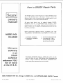
How
Sears
to ORDER
Repair
Parts
The Model Number will be found on a plate attached to your
saw, at the left-hand side of the base. Always mention the
Model Number when requesting service or repair parts for your
CRAFTSMAN
124NCH BAND SAW/SANDER.
owners
manual
All parts
ROEBUCK
listed
AND
herein may be ordered
CO. or StMPSONS-SEARS
through
SEARS,
LIMITED.
When
ordering parts by mail, selling prices will be furnished on request or parts will be shipped at prevailing prices and you will
be billed accordingly.
WHEN ORDERING
REPAIR
FOLLOWING
INFORMATION
MODEL NO.
113.24201
1. The PART NUMBER
3. The MODEL NUMBER
113,24201
PARTS, ALWAYS
AS SHOWN IN
GIVE THE
THIS LmST.
2. The PART DESCRIPTION
4. The NAME OF ITEM -CRAFTSMAN
12-INCH
BAND SAW/SANDER
SER VICE
is at
YOUR
SERVICE
wherever
YOU
live
Your
Sears merchandise
takes on added value when
you dis-
cover that Sears has over 2,000 Service Units throughout
the
country.
Each is staffed by Sears-trained, professional technicians using Sears approved parts and methods.
or move
in the U.S.A.
SEARS,
ROEBUCK
Part No. 69079
AND
CO.,
Chicago,
IL 60684
Form
U.S.A.
No. SP4016
and
1
SIMPSONS-SEARS
LIMITED,
Toronto
Printed
i_ U.S.A.!l/73