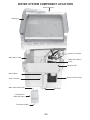
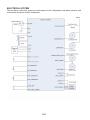
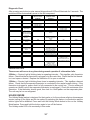
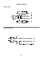
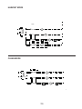
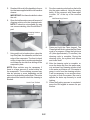
1
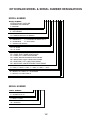
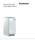
KAR-19
TECHNICAL EDUCATION
2007 DESIGN
15q & 18q AUTOMATIC
ICE MAKERS
KUIA15NRH*11
KUIA15PRL*11
KUIA15NLH*11
KUIA15PLL*11
KUIA18NNJ*11
KUIA18PNL*11
Intoductory Models
* Denotes Color Designation
JOB AID 4317408
FORWARD
This KitchenAid Job Aid “2007 Design 15" & 18" Automatic Ice Makers” (Part No. 4317408),
provides the In-Home Service Professional with information on the installation, operation, and
service of the 2007 Design 15" & 18" Automatic Ice Makers. For specific information on the model
being serviced, refer to the “Use and Care Guide,” or “Tech Sheet” provided with the ice maker.
The Wiring Diagram and Strip Circuits used in this Job Aid are typical and should be used for
training purposes only. Always use the Wiring Diagram supplied with the product when servicing
the ice maker.
GOALS AND OBJECTIVES
The goal of this Job Aid is to provide detailed information that will enable the In-Home Service
Professional to properly diagnose malfunctions and repair the KitchenAid 2007 Design 15" & 18"
Automatic Ice Makers.
The objectives of this Job Aid are to:
• Understand and follow proper safety precautions.
• Successfully troubleshoot and diagnose malfunctions.
• Successfully perform necessary repairs.
• Successfully return the ice maker to its proper operational status.
WHIRLPOOL CORPORATION assumes no responsibility for any repairs made
on our products by anyone other than In-Home Service Professionals.
Copyright © 2007, Whirlpool Corporation, Benton Harbor, MI 49022
- ii -
TABLE OF CONTENTS
Page
GENERAL .............................................................................................................................. 1-1
Ice Maker Safety ................................................................................................................ 1-1
KitchenAid Model & Serial Number Designations .............................................................. 1-2
Model & Serial Number Label Location.............................................................................. 1-3
Specifications ..................................................................................................................... 1-4
INSTALLATION INFORMATION ............................................................................................ 2-1
Electrical Supply Requirements ......................................................................................... 2-1
Water Supply And Drain Connections ................................................................................ 2-2
THEORY OF OPERATION .................................................................................................... 3-1
Operating Systems............................................................................................................. 3-1
Operational Modes ............................................................................................................. 3-5
Models With Internal Drain Pumps..................................................................................... 3-8
COMPONENT ACCESS ........................................................................................................ 4-1
Component Locations ........................................................................................................ 4-1
Removing The Bin Thermistor, Cutter Grid, Evaporator Thermistor,
& Water Distributor ......................................................................................................... 4-2
Removing The Electronic Control Housing Components ................................................... 4-5
Removing The Water Recirculation Pump ......................................................................... 4-7
Removing The Reservoir Drain Pump & Water Level Sensor............................................ 4-8
Removing The Condenser Fan Motor ................................................................................ 4-9
Removing The Evaporator ............................................................................................... 4-12
Removing The Measured Fill Water Valve ....................................................................... 4-16
Removing The Hot Gas Valve & Solenoid ....................................................................... 4-17
Removing The Condenser ............................................................................................... 4-18
Removing The Compressor ............................................................................................. 4-19
Removing The Internal Drain Pump ................................................................................. 4-21
Removing The Ice Maker Door & Gasket (15" Models) ................................................... 4-22
Removing The Ice Maker Door & Gasket (18" Models) ................................................... 4-23
COMPONENT TESTING ........................................................................................................ 5-1
Bin Thermistor .................................................................................................................... 5-1
Evaporator Thermistor ....................................................................................................... 5-1
Cutter Grid.......................................................................................................................... 5-2
Dual Transformer ............................................................................................................... 5-2
Water Recirculation Pump ................................................................................................. 5-3
Reservoir Drain Pump ........................................................................................................ 5-3
Water Level Sensor ............................................................................................................ 5-4
Condenser Fan Motor ........................................................................................................ 5-4
Measured Fill Water Valve ................................................................................................ 5-5
Hot Gas Valve Solenoid ..................................................................................................... 5-5
Compressor, Overload Protector, & Relay ......................................................................... 5-6
- iii -
Page
DIAGNOSTICS & TROUBLESHOOTING ............................................................................. 6-1
Water And Its Effect On Making Ice ................................................................................... 6-1
Troubleshooting Chart ........................................................................................................ 6-2
Diagnostic Flow Chart For Ice Maker Control Board ......................................................... 6-5
WIRING DIAGRAM & STRIP CIRCUITS ............................................................................... 7-1
Wiring Diagram .................................................................................................................. 7-1
Strip Circuits ....................................................................................................................... 7-2
TECH TIPS ............................................................................................................................. 8-1
Cleaning The Ice Maker ..................................................................................................... 8-1
Cleaning The Evaporator Plate ....................................................................................... 8-1
- iv -
GENERAL
ICE MAKER SAFETY
Your safety and the safety of others are very important.
We have provided many important safety messages in this manual and on the appliance.
Always read and obey all safety messages.
This is the safety alert symbol.
This symbol alerts you to potential hazards that can kill or hurt you and others.
All safety messages will follow the safety alert symbol and either the word
“DANGER” or “WARNING.” These words mean:
WARNING
You can be killed or seriously injured if you don’t
immediately follow instructions.
DANGER
You can be killed or seriously injured if you don’t
follow instructions.
All safety messages will tell you what the potential hazard is, tell you how to reduce the chance
of injury, and tell you what can happen if the instructions are not followed.
1-1
KITCHENAID MODEL & SERIAL NUMBER DESIGNATIONS
MODEL NUMBER
MODEL NUMBER
INTERNATIONAL SALES IND.
OR MARKETING CHANNEL
IF PRESENT
K UI A 15 NR H S
PRODUCT GROUP
K = KITCHENAID
PRODUCT IDENTIFICATION
UI = UNDERCOUNTER ICE MAKER
MERCHANDISING SCHEME
A = ARCHITECT
C = CULINARY & ARCHITECT II
S = STANDARD
O = OUTDOOR
V = SIGNATURE SERIES
CAPACITY / SIZE / SERIES / CONFIGURATION
15 = 15" WIDE
18 = 18" WIDE
FEATURES
PR = PUMP, RIGHT HAND DOOR SWING
PL = PUMP, LEFT HAND DOOR SWING
PN = PUMP, NON-REVERSIBLE DOOR SWING
NR = NON-PUMP, RIGHT HAND DOOR SWING
NL = NON-PUMP, LEFT HAND DOOR SWING
NN = NON-PUMP, NON-REVERSIBLE DOOR SWING
YEAR OF INTRODUCTION
H = 1999, J = 2000, K = 2001, L = 2002, S = 2006, T = 2007
COLOR CODE
B = BLACK, W = WHITE, S = STAINLESS
T = BISCUIT, M = METEORITE
ENGINEERING CHANGE (NUMERIC)
SERIAL NUMBER
SERIAL NUMBER
DIVISION RESPONSIBILITY
E = EVANSVILLE, IN
YEAR OF PRODUCTION
T = 2006, U = 2007
WEEK OF PRODUCTION
04 = 4th WEEK
PRODUCT SEQUENCE NUMBER
E T 04 54321
1-2
0
MODEL & SERIAL NUMBER LABEL LOCATION
The Model/Serial Number label location is shown below.
Model & Serial
Number Location
1-3
SPECIFICATIONS
AC Power Supply . . . . . . . . . . . . . . . . . . . . . . . . . . . . . .97 to 127 VAC (rated 115VAC), 60 Hz
Amperage . . . . . . . . . . . . . . . . . . . . . . . . . . . . . . . . . . . . . . . . . . . . . . . . . . . . . 6.5 Amps (max)
Minimum Circuit Capacity . . . . . . . . . . . . . . . . . . . . . . . . . . . . . . . . . . . . . . . . . . . . . . .15 Amps
Ice Production per 24 hours (Approximate)
Ambient Temperature
Water Temperature
60⋅F (15⋅C)
70⋅°F (21°C)
46 lbs (21 kg)
80⋅°F (27°C)
47 lbs (21 kg)
90⋅°F (32°C)
40 lbs (18 kg)
100⋅°F (38°C)
40 lbs (18 kg)
110⋅°F (43°C)
38 lbs (17 kg)
Ice Shape . . . . . . . . . . . . . . . . . . . . . . . . . . . . . . . . . . . . . . . . . . . . . . . . . . . 3/4" x 3/4" Square
Ice Thickness @ Normal Setting (Approximate) . . . . . . . . . . . . . . . . . . . . . . . . . 0.32" (8.1 mm)
Ice Thickness @ Thin Setting (Approximate) . . . . . . . . . . . . . . . . . . . . . . . . . . . 0.28" (7.0 mm)
Ice Thickness @ Thick Setting (Approximate). . . . . . . . . . . . . . . . . . . . . . . . . . 0.39" (9.9 mm)
15 Inch Storage Capacity (Approximate). . . . . . . . . . . . . . . . . . . . . . . . . . . . . . 25 lbs. (11.3 kg)
18 Inch Storage Capacity (Approximate). . . . . . . . . . . . . . . . . . . . . . . . . . . . . .35 lbs. (15.9 kg)
Exterior Dimensions (W x D x H) . . . 15" or 18" x 24" x 34" (381 or 457.2 x 609.6 x 863.6 mm)
Exterior Finish . . . . . . . . . . . . . . . . . . . . . . . . . . . . . . . . . . . . . Stainless Steel or Painted Steel
Net Weight . . . . . . . . . . . . . . . . . . . . . . . . . . 15" = 94 lbs. (42.6 kg) 18" = 123 lbs. (55.8 kg)
Cube Thickness Control . . . . . . . . . . . . . . . . . . . Water Level Sensor & Control Board Setting
Harvest Control . . . . . . . . . . . . . . . . . . . . . . . . . . . . . . . . . . . . . . .Thermistor under Evaporator
Bin Ice Level Control . . . . . . . . . . . . . . . . . . . . . . . . . . . . . . . . . . . . . .Thermistor on side of Bin
Refrigerant . . . . . . . . . . . . . . . . . . . . . . . . . . . . . . . . . . . . . . . . . . . . . . . . . . . . . . . . . . . . R134a
Ambient Temperature . . . . . . . . . . . . . . . . . . . . . . . . . . . . . . . . . . . . . . . . . . . . . . . 55 to 100⋅F
Water Pressure . . . . . . . . . . . . . . . . . . . . . . . . . . . . . . . . . . . . . . . . . . . . . . . . . . 20 to 120 psig
Water Consumption (Dependent On Water Pressure) . . . . . . . . . . 6 to 10 gallons per 4 hours
1-4
INSTALLATION INFORMATION
ELECTRICAL SUPPLY REQUIREMENTS
IMPORTANT: If this product is connected to
a GFCI (Ground Fault Circuit Interrupter) protected outlet, nuisance tripping of the power
supply may occur, resulting in the loss of cooling. Ice quality may be affected. If nuisance
tripping has occurred, and if the condition of
the ice appears poor, dispose of it.
WARNING
Recommended Grounding Method
Electrical Shock Hazard
For personal safety, this appliance must be
grounded. This appliance is equipped with a
power supply cord having a 3-prong grounding
plug. To minimize possible shock hazard, the
cord must be plugged into a mating, 3- prong,
grounding-type wall receptacle, grounded in
accordance with the National Electrical Code
and local codes and ordinances. If a mating
wall receptacle is not available, it is the personal responsibility of the customer to have
a properly grounded, 3-prong wall receptacle
installed by a qualified electrician.
Plug into a grounded 3 prong outlet.
Do not remove ground prong.
Do not use an adapter.
Do not use an extension cord.
Failure to follow these instructions can
result in death, fire, or electrical shock.
Before you move the ice maker into its final
location, it is important to make sure you have
the proper electrical connection:
• A 115 Volt, 60 Hz, AC only 15- or 20- amp electrical supply, properly grounded in accordance
with the National Electrical Code and local
codes and ordinances, is required.
• It is recommended that a separate circuit,
serving only the ice maker, be provided. Use
a receptacle which cannot be turned off by
a switch or pull chain.
2-1
WATER SUPPLY AND DRAIN CONNECTIONS
8.
Use 1/4" (6.35 mm) O.D. copper tubing
for the cold water supply and:
a) Measure from the connection at the
back of the ice maker to the cold water
pipe.
b) Add an extra 36" (91.4 cm) to ensure
that you have the proper length. Make
sure both ends of the copper tubing are
cut square.
c) Slip a compression sleeve and compression nut over the ends of the copper
tubing.
d) Insert the end of tubing into the water
shutoff outlet as far as it will go, and
screw the compression nut onto the
outlet. Tighten the compression nut
with an adjustable wrench, but do not
overtighten it.
9. Place the free end of the copper tubing into
a container or sink, and turn on the main
water supply. Flush the tubing until water
is clear, and then turn off the shutoff valve
on the water pipe. NOTE: Always drain the
water line before making the final connection to the inlet of the water valve to avoid
a possible water valve malfunction.
10. Bend the copper tubing to meet the water
line inlet, located on the back of the ice
maker cabinet, as shown below.
CONNECTING THE WATER LINE
1.
2.
Turn off the main water supply.
Turn on the nearest faucet and allow it to
run long enough to clear line of water.
3. Find a 1/2"(12.70 mm) to 1-1/4" (3.18
cm) vertical cold water pipe near the ice
maker.
NOTE: A horizontal pipe will work, but drill on
the top side of the pipe, not the bottom. This
will keep water away from the drill motor, and
also keeps normal sediment from collecting in
the valve.
4. Using a grounded drill, a 1/4" (6.35 mm)
hole in the cold water pipe you have selected.
5. Fasten a shutoff valve to the cold water
pipe with a pipe clamp. Make sure that the
outlet end is firmly in the 1/4" (6.35 mm)
drilled hole, and that the washer is under
the pipe clamp.
IMPORTANT: Do not use a piercing-type, or
a 3/16" (4.76 mm) saddle-type valve. These
can reduce water flow and easily become
clogged.
6.
7.
Tighten the packing nut.
Tighten the pipe clamp screws carefully
and evenly so that the washer makes a
watertight seal. Do not overtighten the
pipe clamp. If the water line is soft copper
tubing, you could crush it.
2-2
11. Thread the nut onto the coupling at the
end of the copper tubing. Tighten the nut
by hand. Then tighten it with a wrench two
more turns. Do not overtighten.
SIDE VIEW
15" Models
CONNECTING THE DRAIN
Gravity Drain System
Connect the ice maker drain to your drain
in accordance with all state and local codes
and ordinances. If the ice maker is provided
with a gravity drain system, use the following
guidelines when installing the drain lines. This
will avoid water from flowing back into the ice
maker storage bin and potentially flowing onto
the floor, causing water damage.
• Drain lines must have a minimum of 5/8"
(15.88 mm) inside diameter.
• Drain lines must have a 1" drop per 48"
(2.54 cm drop per 122 cm) of run, or 1/4"
drop per 12" (6.35 mm per 30.48 cm) and
not have any low points where water can
settle.
• The floor drains must be large enough to
accommodate drainage from all drains.
• The ideal installation has a standpipe with a
1-1/2" (3.81 cm) to 2" (5.08 cm) PVC drain
reducer installed directly below the outlet of
the drain tube, as shown. You must maintain
a 1" (2.54 cm) air gap between the drain hose
and the standpipe.
• It may be desirable to insulate the drain line
up to the drain inlet.
18" Models
1.
2.
3.
4.
2-3
Drain Hose
1" (2.54 cm) Air Gap
PVC Drain Reducer
Center of drain should be 20" (50.8 cm) back on
15" models from front of door and 23" (58.4cm)
back on 18" models from front of door, with or
without the 3/4" (1.91 cm) panel on the door.
Drain Pump System (On Some Models)
Connect the ice maker drain to your drain in
accordance with the International Plumbing
Code and any local codes and ordinances.
NOTE: If the drain hose becomes twisted and
water cannot drain, the ice maker will not operate.
Connecting the Drain
After ensuring that the drain system is adequate, follow these steps to properly place
the ice maker:
1. Plug in ice maker or reconnect power.
WARNING
Excessive Weight Hazard
Use two or more people to move and
install ice maker.
Failure to do so can result in back or
other injury.
2.
WARNING
3.
Electrical Shock Hazard
Plug into a grounded 3 prong outlet.
Do not remove ground prong.
Do not use an adapter.
Do not use an extension cord.
Failure to follow these instructions can
result in death, fire, or electrical shock.
4.
2-4
Style 1 - For gravity drain system, push
the ice maker into position so that the ice
maker drain tube is positioned over the
PVC drain reducer. Style 2 - For drain
pump system connect the drain pump
outlet hose to the drain. See “Drain Pump
System” earlier in this section.
Recheck the ice maker to be sure that it
is level.
If it is required by your local sanitation
code, seal the cabinet to the floor with
an approved caulking compound after
all water and electrical connections have
been made.
THEORY OF OPERATION
OPERATING SYSTEMS
There are three operating systems in the ice
maker:
• Refrigeration System
• Water System
• Electrical System
There are two very important additions to the
refrigeration system in the ice maker: the Hot
Gas Valve, and the Condenser Accumulator
Tube. The components operate as follows:
• Hot Gas Valve - Allows high pressure
refrigerant gas to bypass the condenser
and flow through the condenser accumulator tube.
• Condenser Accumulator Tube - Hot gas
pushes liquid refrigerant through the
accumulator tube into the evaporator,
helping to evenly heat the evaporator plate so that the ice slab releases
quickly and evenly.
REFRIGERATION SYSTEM
The refrigeration system in the ice maker is
very similar to the system used in other refrigeration appliances. The refrigerant used in this
unit is R134a.
3-1
A water softener, or poly phosphate feeder, will
not cure all of the problems associated with hard
water, but they can be used to reduce scale
buildup in the ice maker. NOTE: Some poly
phosphate feeders will cause a slime buildup
in the water system when the water supply has
a low mineral content.
The ice maker’s water system is shown on
next page.
WATER SYSTEM
The water system provides:
• Fresh water for ice production
• Water recirculation as ice is produced
• Water removal after ice is produced
The water system circulates water to freeze
into ice on the evaporator during the freeze
cycle. During the harvest cycle, it drains away
minerals and contaminates. During the clean
cycle, cleaning solution is circulated to clean
the system of minerals and contaminates.
The hardness of the water supplied to the ice
maker will affect the quality of the ice that is
produced. It may also affect the operation of
the water system.
3-2
WATER SYSTEM COMPONENT LOCATIONS
Water Distributor
Evaporator
Water Level Sensor
Water Return Tube
Water Recirculation
Pump
Reservoir Pan
Manual Drain
Reservoir Drain Pump
Drain Overflow
Water Valve Outlet Tube
Bin Drain
Measured Fill
Water Inlet Valve
From Water Supply
3-3
ELECTRICAL SYSTEM
The ice maker’s electrical system provides power for the refrigeration and water systems, and
controls the operation of each component.
3-4
OPERATIONAL MODES
During the Freeze mode, some of the hot gas
that is in the condenser accumulating tube,
condenses to a liquid, and remains in the accumulating tube.
During the later stages of the Freeze mode, as
the ice slab forms on the evaporator freezing
plate, some of the refrigerant passing through
the evaporator will not evaporate into a gas, but
will remain a liquid. This liquid refrigerant will
settle in the accumulator, while the refrigerant
vapor is sucked off through the suction tube at
the top of the accumulator. This accumulated
liquid refrigerant will eventually be directed to
the evaporator to quickly warm the evaporator
plate during the Harvest mode.
NOTE: It is very important that the accumulator
is not tilted out of a horizontal position. If moved,
it could cause compressor failure.
There are four main operational modes for the
ice maker (more detailed operation is found in
the flow chart on page 6-5):
• Freeze
• Harvest
• Clean
• Service (Diagnostics)
ICE MAKING CYCLE
In addition, there are three possible “Off” cycles
for the ice maker. They occur when:
1. The bin is full of ice and the LED is illuminated “ON/OFF” (Idle mode).
2. The "On/OFF” control switch has been
held for three seconds. The ON/OFF
LED will go out.
3. The Holiday Mode.
Electrical System
Line Voltage is supplied to the electrical control
switches and the primary side of the step-down
dual transformer. The dual transformer reduces
120 VAC to 8.75 VAC for the cutter grid and
the bin light and 12 VAC for the drain and recirculating pumps. The electronic control board
directs 12 VAC to the water recirculating and
reservoir drain pumps, and 120 VAC to the
hot gas solenoid, condenser fan motor, and
compressor. The measured fill water valve will
always have 120 VAC on the BK and WH wires
and 14 VDC on the OR/WH and BK/RD wires.
An evaporator thermistor supplies temperature
information to the electronic control to determine
when to terminate the harvest cycle.
Water System
The water recirculating pump moves the water
from the reservoir pan up to the distributor,
where it flows out over the evaporator freezing plate.
Water that does not freeze on the evaporator
plate runs off the front edge, and falls back into
the reservoir, where it is recirculated back to
the water distributor.
As the ice slab forms, the minerals in the water
are on the surface of the ice. The water flowing over the top of the ice slab washes these
minerals back into the water reservoir pan. The
water continues to recirculate until the water
level in the reservoir drops to the bottom of the
water level sensor. When the water level in the
reservoir drops below the sensor, the control
terminates the freeze mode and initiates the
harvest mode.
The control signals the measured fill valve to fill
to the selected water level setting. The measured fill valve uses a flow meter to accurately fill
to the correct volume. Thin Ice uses 32 ounces
(954cc), Normal Ice 37 ounces (1106cc), and
Thick Ice 42.5 ounces (1258cc).
Refrigeration System
The hot gas refrigerant, under high pressure, is
forced through the condenser, where it changes
into a liquid, and flows through the drier and
capillary tube into the evaporator. Under low
pressure in the evaporator, the liquid refrigerant
absorbs heat from the water flowing over the
evaporator as the refrigerant evaporates into
a gas. As a low pressure gas, the refrigerant
flows back through the suction line of the heat
exchanger, to the compressor.
3-5
The electronic control board operates the various components and systems in the ice maker
for each of the Freeze and Harvest modes.
HARVEST MODE
Electrical System
When the water level in the reservoir drops
below the water level sensor it signals the
electronic control to terminate power to the
condenser fan, and then the water recirculating
pump. The reservoir drain pump is activated
to fully drain the reservoir. Power is then supplied to the hot gas valve and a fill request is
sent to the measured fill valve. The fill valve
fills to the requested volume while the hot gas
valve is energized for the balance of the harvest mode.
If the evaporator thermistor is unplugged, the
evaporator defaults to a timed 4 minute harvest.
CLEAN MODE
Electrical System
The electronic control board operates the
various components and systems during the
Clean mode.
For the order of the components cycled, see
the flow chart on page 6-13.
Water System
When the service control switch is in the “Clean”
position, the water recirculating pump circulates
the cleaning solution that has been added to the
reservoir, up to the water distributor, across the
evaporator, and back into the reservoir, where
it is recirculated. The compressor and hot gas
valve operate to heat the evaporator.
If the water level sensor is disconnected or
open, the control defaults to 25 minutes of
freeze time. The cleaning indicator LED feature will not function if the water level sensor
is disconnected.
DIAGNOSTIC MODE
1.
Do not continue with the diagnosis of the ice
maker if a fuse is blown, a circuit breaker
is tripped, or if there is less than a 120 volt
power supply at the wall outlet.
2. All units that have failed during the first few
days of use should be checked for loose
connections or miswiring.
Entering and Navigating — Manual
Diagnostics
• Turn the product on. Within 10 seconds of
Power On, press and hold the On and the
Clean buttons. Release both buttons when
all user interface LEDs begin to flash.
• Within 5 seconds of all LEDs flashing, push
any other button on the user interface. This
begins manual diagnostics.
• If no button is pressed within 5 seconds, the
product goes into the automatic diagnostic
mode used at the assembly plant. Each
component is cycled for 5 seconds.
• The Service button (or Off button on some
models) is used to advance through each
step.
• To exit manual diagnostics, press the Power
button (or On button on some models)
Refrigeration System
The hot gas valve opens, allowing high pressure refrigerant gas to bypass the condenser,
and flow through the condenser accumulating
tube. The hot gas pushes the liquid refrigerant
that has accumulated in the accumulator tube
up into the evaporator. The hot liquid refrigerant
evenly heats the evaporator plate so that the
ice slab releases quickly and evenly.
The ice slab, when released, slides off of the
evaporator plate onto the cutter grid.
Water System
The electronic control board sends a signal to
the water valve. The signal tells the water valve
how much water to be filled, allowing water to
flow into the water reservoir pan. The water
fill volume is determined by the ice thickness
setting.
As a result of the hot gas flow and the ice sliding
off the evaporator plate, the evaporator temperature begins to rise. When the evaporator
thermistor reaches the set temperature (52°F),
the unit switches to the Freeze mode. This cycling between Freeze and Harvest, continues
until the ice bin is full.
3-6
Diagnostic Chart
After pressing any button to enter manual diagnostics all LEDs will illuminate for 5 seconds. The
controls will then automatically move to the first component.
Order
Component
On/Off LED
(On for some
models)
Service LED
(Off for some
models)
Clean LED
Feature Light (for
some models)
1
Entry into Test
Mode
ON
ON
ON
ON
2
Bin Thermistor
OFF
OFF
OFF
3
Evaporator
Thermistor
ON Solid--OK
2 blinks--Open
4 blinks--Short
OFF
OFF
OFF
4a
Water Valve
4 min time out
Service button
press will advance
to step 6
Water Level
Sensor
OFF
ON Solid--reservoir full
Blinking--reservoir
empty
ON Solid--OK
2 blinks--Open
4 blinks--Short
ON
OFF
OFF
ON
OFF
5
Recirculation
Pump
ON
ON Solid--reservoir full
Blinking--reservoir
empty
ON
ON
OFF
6
Reservoir Drain
Pump
ON
OFF
OFF
OFF
7
Compressor and
Condenser Fan
Motor
ON Solid while cooling
ON
OFF
8
Compressor and
Hot Gas Valve
ON Solid while heating
ON Solid while heating
OFF
Twice Ice
OFF
Blinking when evap
thermistor reaches
4.5ºF; full frost pattern
should be visible
ON Solid while heating
Blinking when evap
thermistor reaches 52ºF
OFF
OFF
Ice Thickness
OFF
ON Solid--No delay
Blinking--10 min delay
between cycles
Press Clean button to
cycle between settings
OFF
4b
9
10
2 Blinks--Thin
4 Blinks--Normal
6 Blinks--Thick
Press Clean button to
cycle between settings
OFF
ERROR DISPLAYS
These errors will occur at any time during normal operation if a thermistor fails.
2 Blinks — Service Light is blinking twice in repeating intervals – This signifies a bin thermistor
failure. Check that the bin thermistor is plugged in to the control box. Check that the bin thermistor is not open or shorted. Replace the thermistor if it is open or shorted.
3 Blinks — Service Light is blinking three times in repeating intervals – This signifies a harvest
failure. Check that the evaporator thermistor is connected to the sealed system tubing. If the
thermistor is plugged in, ensure that it is fully connected to the control box. (The ice maker will
operate on a timed cycle if the evaporator thermistor is unplugged.) Check the resistance of the
thermistor. If the thermistor checks good, then look for a frost pattern on the evaporator plate.
The unit may be low on refrigerant.
HOLIDAY MODE
The Holiday Mode feature is designed for the traveler or for those whose religious observances
require turning off the lights and the ice maker. By selecting this feature, ice production and the
interior lights will be disabled. Press and hold the Holiday Mode button to turn on the Holiday
Mode feature. Press and hold the button again to turn off the feature.
The Holiday mode LED is lite constantly in this mode.
3-7
MODELS WITH INTERNAL DRAIN PUMPS
into the pump inlet, and then into the drain pump
chamber. As the water level rises, it bridges the
“full” contacts, and the pump starts to run. The
pump discharges the water through the outlet
and the check valve. When the “full” connection
is removed, the pump runs for an additional 12
seconds to empty the tank.
If the water level in the drain pump continues
to rise, due to a slow or blocked drain, or a
blocked vent hose, and touches the “overfill”
contact, power will be turned off to the drain
pump’s 120 VAC outlet, causing the ice maker
to turn off.
The power cord on the internal drain pump is
connected to a 120 VAC wall outlet. The ice
maker is then connected to the 120 VAC outlet
on the drain pump. If the drain pump fails, or if
the drain becomes blocked, power is shut off
to the 120 VAC outlet on the drain pump.
When the unit is first plugged in, the drain
pump will run for 20 seconds. The power can
be disconnected and reconnected to verify that
the pump is operating properly.
Water from the ice maker reservoir, or melting
ice from the bin, drains down the bin drain tube
Vent Outlet
Pump Inlet
White
Contacts Sense Continuity
Through The Water
Black
Pump Outlet &
Check Valve
Green
Overfill Contact
Full Contacts
Connector Hose
(Contains Screen Washer)
Screen
Washer
3-8
COMPONENT ACCESS
This section instructs you on how to service each component inside the 2007 Design 15” & 18”
Automatic Ice Makers. The components and their locations are shown below.
COMPONENT LOCATIONS
Dual Transformer
Light Switch Electronic Control Board
Push-button
Switch
Evaporator
NOTE: The Evaporator
Thermistor Is Located On
Tubing Below Evaporator
Cutter Grid
Bin
Thermistor
Water Level
Sensor
Water
Recirculation
Pump
Reservoir
Drain Pump
Compressor
Condenser
Fan Motor
Hot Gas Valve &
Solenoid (Behind
Condenser)
Condenser
Measured Fill
Water Valve
Condenser Accumulator Tube
4-1
REMOVING THE BIN THERMISTOR, CUTTER GRID,
EVAPORATOR THERMISTOR, & WATER DISTRIBUTOR
6.
WARNING
To remove the bin thermistor:
a) Disconnect the bin thermistor connector
from the bottom of the control housing.
b) Pull the bin thermistor out of the retaining clamp and remove it.
Electrical Shock Hazard
Control Housing
Plug into a grounded 3 prong outlet.
Do not remove ground prong.
Do not use an adapter.
Do not use an extension cord.
Failure to follow these instructions can
result in death, fire, or electrical shock.
1.
2.
3.
4.
5.
Connector
Unplug ice maker or disconnect power.
Open the ice maker door.
Cover or remove the ice from the storage
bin.
Place a cloth in the drain hole to avoid
hardware from falling inside.
Remove the two hex-head screws from the
cutter grid cover and remove the cover.
Bin Thermistor
Retaining Clamp
7.
Cutter Grid Cover
To remove the cutter grid:
a) Disconnect the cutter grid and bin
thermistor connectors from the bottom
of the control housing.
b) Remove the two hex-head screws from
both sides of the cutter grid. The longer
screw and white spacer are on the right
side.
Spacer Bracket (Left Side)
18˝ Models
Cutter Grid Cover Screws
Cutter Grid Cover
Bin Thermistor Connector
Cutter Grid Connector
Cutter Grid Screws
4-2
c) Slide the cutter grid forward and out of
the unit and place it on a work surface.
Be careful not to scratch the ice maker
liner.
d) Remove the spacer from the right cutter
grid bracket tab.
8.
To remove the evaporator thermistor:
a) Remove the cutter grid from the unit
(see step 7 on page 4-2 for the procedure).
b) Disconnect the evaporator thermistor
connector from the bottom of the control
housing.
c) Remove the two hex-head mounting
screws from the water trough and pull
the trough from the unit.
Control Housing
Evap Thermistor Connector
Water Trough Screws
Cutter Grid
Spacer
e) Unsnap the two ice guides from the
cutter grid tabs. There should be a
slight outward tilt after the guides are
installed. Bend the metal tabs outward
if necessary.
Water Trough
d) Reach behind the accumulator, and
unclip the evaporator thermistor from
the evaporator tubing and remove it.
Cutter Grid
Ice Guides
Evaporator Thermistor
Bottom Of The Evaporator
Accumulator
Continued on the next page.
4-3
9.
To remove the water distributor:
a) Remove the cutter grid from the unit
(see step 7 on page 4-2 for the procedure).
b) Pull out on the left and right water distributor retainers, and remove the tabs
from the slots in the evaporator. Pull
the distributor forward and remove the
water hose.
Water Distributor
Water Hose
Tab
Water Distributor
4-4
REMOVING THE ELECTRONIC CONTROL
HOUSING COMPONENTS
NOTE: The control housing components consist of:
• (1) Electronic control board
• (2) Dual transformer
• (3) Light switch
• (4) Push-button switch assembly
WARNING
Electrical Shock Hazard
Disconnect power before servicing.
Replace all parts and panels before
operating.
Failure to do so can result in death or
electrical shock.
1.
2.
3.
4.
5.
6.
2
Unplug ice maker or disconnect power.
Open the ice maker door.
Cover or remove the ice from the storage
bin.
Remove the cutter grid cover and the cutter
grid (see page 4-2 for the procedures).
Disconnect the remaining two connectors
(bin and evaporator thermistors) from the
bottom of the control housing.
Remove the four hex-head screws from
the control housing and lower the housing
so that you can access the components.
3
7.
1
4
To remove the electronic control
board:
a) Disconnect the six harness connectors
from the board terminals.
b) Remove the two mounting screws.
Six (6) Harness Connectors
Screw
Control Panel
Electronic Control Board
Screw
Continued on the next page.
4 Control Housing Screws
4-5
8.
To remove the dual transformer:
a) Disconnect the six pin wire connector
from harness.
b) Remove the two mounting screws from
the transformer bracket.
c) Disconnect the green ground wire from
its terminal.
NOTE: Reconnect the green ground wire when
installing new dual transformer.
NOTE: If the switch assembly or light switch
is replaced, the replacement part and decorative overlay must be ordered using the model
number of the ice maker. The service replacement switch is not supplied with a decorative
overlay.
9.
To remove the light switch or push-button switch assembly:
a) Peel off the decorative overlay from the
front of the control housing.
Decorative Overlay
Dual Transformer
b) Disconnect the molex plug from switch
assembly. Press the back of switch assembly and push the switch assembly
out of the housing.
Green Ground Wire
Locking Arm
Screw (1 of 2)
WARNING
Light Switch
Electrical Shock Hazard
Connect green ground wire to ground
terminal.
Failure to do so can result in death or
electrical shock.
4-6
Switch Assembly
REMOVING THE WATER RECIRCULATION PUMP
6.
Remove the hex-head screw from the water
recirculation pump shield and remove the
shield (see the lower left photo).
7. Disconnect the water fill tube from the
pump mounting bracket.
8. Disconnect the two wire recirculation and
drain pump connectors from the harness
block.
9. Remove the two thumbscrews from the
reservoir and remove the reservoir from
the ice maker.
10. Remove the recirculation pump outlet
tube.
11. Remove three hex-headed screws from
the pump mounting bracket and remove
pump assembly.
12. Separate the recirculation pump from the
bracket.
WARNING
Electrical Shock Hazard
Disconnect power before servicing.
Replace all parts and panels before
operating.
Failure to do so can result in death or
electrical shock.
1.
2.
3.
4.
5.
Unplug ice maker or disconnect power.
Open the ice maker door.
Remove the ice from the storage bin.
Unscrew the drain cap from the reservoir, drain the water, and replace the cap
tightly.
Place a cloth in the drain hole to avoid
hardware from falling inside.
2-Wire Connector
Spacer Bracket (Left Side) 18˝ Models
Water Fill Tube
Recirculation Pump
Outlet Tube
Recirculation
Pump Shield
Screw
Water Reservoir
Thumbscrew
Thumbscrew
Drain Cap
Drain Pump
4-7
REMOVING THE RESERVOIR DRAIN PUMP
& WATER LEVEL SENSOR
6.
WARNING
To remove the water level sensor:
a) Disconnect the water level sensor electrical connection.
b) Remove the retaining clips, if present.
c) Pull the sensor up and out of the
bracket.
Electrical Shock Hazard
Disconnect power before servicing.
Replace all parts and panels before
operating.
Failure to do so can result in death or
electrical shock.
1.
2.
3.
4.
5.
Unplug ice maker or disconnect power.
Open the ice maker door.
Unscrew the drain cap from the reservoir, drain the water, and replace the cap
tightly.
Remove the recirculating pump cover hexhead screw.
To remove reservoir drain pump:
a) Disconnect the reservoir drain pump
electrical connection.
b) Remove the pump retaining screw and
bracket.
c) Rotate the pump 1/4 turn and pull it
down and out of reservoir.
Screw
Water Level Sensor
Water Recirculation
Pump Shield
Water Reservoir
Screw
Drain Cap
Drain Pump
4-8
REMOVING THE CONDENSER FAN MOTOR
6.
WARNING
7.
8.
Remove the two 5/16” screws from the
front of the cabinet.
Remove two hex-head screws from the
measured fill water valve bracket.
Allow the valve to drop down out of the
way.
Electrical Shock Hazard
Disconnect power before servicing.
Replace all parts and panels before
operating.
Failure to do so can result in death or
electrical shock.
1.
2.
3.
4.
5.
Hot Gas Valve
Unplug ice maker or disconnect power.
Open the ice maker door.
Remove the ice from the storage bin.
Disconnect the water and drain lines from
the ice maker and remove the unit from its
installation.
Remove the four hex-head screws from
the front panel and remove the panel.
Measured Fill Water Valve
Screw
Water Inlet Tubing
Screw
NOTE: If the unit you are servicing is equipped
with an internal drain pump, perform steps 9
and 10. If the unit does not have an internal
pump, skip those steps, and proceed to step
11 on the next page.
9. From the back of the unit, remove the four
screws from the unit compartment cover
and remove the cover.
Front Panel Screws
Unit Compartment Cover
4 Screws
Continued on the next page.
4-9
10. Disconnect the inlet tube and the vent tube
from the internal drain pump.
Tubing
Internal Drain Pump
12. Disconnect the wire connector from the
condenser fan motor.
13. Remove the four screws (two bottom and
two side) from the condenser fan motor
shroud. Slide the shroud assembly back
towards the compressor, and then lift and
remove the assembly from the unit.
Motor Connector
11. Tilt the front of the cabinet up until you
can access the two side screws on the
condenser fan motor shroud, and secure
the cabinet so that it cannot tip forward or
backward.
Tilt
Condenser Fan Motor Bottom Shroud Screws
Condenser Fan Motor Left Side Shroud Screw
Continued on the next page.
4-10
14. Remove condenser fan motor blade by
pulling the fan blade straight off the shaft.
NOTE: Make sure when reinstalling the fan
blade that the blade is seated completely
on motor shaft.
15. Remove the two hex-head screws from the
condenser fan motor and remove it from
the shroud.
Condenser Fan Motor Screw (1 of 2)
Condenser Fan Blade
4-11
REMOVING THE EVAPORATOR
7.
WARNING
Remove the two 5/16” hex-head screws
from the top hinge and remove the
hinge.
Hinge Screws
Electrical Shock Hazard
Disconnect power before servicing.
Replace all parts and panels before
operating.
Failure to do so can result in death or
electrical shock.
1.
2.
3.
4.
5.
6.
Unplug ice maker or disconnect power.
Open the ice maker door.
Remove the ice from the storage bin.
Remove the cutter grid and the evaporator
thermistor from the unit (see pages 4-2
and 4-3 for the procedures).
Disconnect the bin thermistor connector
from the bottom of the control housing
(see page 4-2).
Remove the top door screw from the ice
maker door, and pull the door off the bottom hinge.
8.
Remove the two front and two rear screws
from the cabinet top.
2 Hex-Head Screws
Screw
Top Door Screw
9.
4-12
Screw
Lift the cabinet top and position it forward
on top of the unit.
10. 18˝ Models Only: Remove the six screws
from the counterbalance plate and remove
the plate from the rear of the unit.
11. From the rear of the unit, remove the six
hex-head screws from the channel cover
and remove the cover.
12. Remove the four screws from the unit compartment cover and remove the cover.
13. Cut the tie wrap from around the tubing
and wire harness inside the channel.
Screw (1 of 6)
Tie Wrap
Counterbalance Plate
18˝ Models
14. Remove the two screws from the reservoir
water trough and remove the trough.
Screw
Water Trough
Screw
Channel Cover
(6 Screws)
Continued on the next page.
Unit Compartment Cover
(4 Screws)
4-13
15. Remove the hex-head screw from the water
recirculation pump shield and remove the
shield.
16. Remove the water fill tube from the notch
in the water recirculation pump bracket,
and pull the free end of the water line up,
out of the unit.
Retainer
Tab
Water Recirculation Pump Shield
Water Distributor
Screw
Hose
Evaporator
Water Fill Tube
Refer to the photos at the top of the next column.
17. Pull out on the left and right water distributor retainers and remove the tabs from the
slots in the evaporator, disconnect it from
the hose, and remove it.
18. Remove the four screws from the evaporator, then carefully lift the evaporator
just high enough to remove the two right
spacers.
2 Screws
2 Screws & Spacers
19. Remove the Permagum from the liner
channel.
4-14
Remove Permagum
20. Lift the cabinet top off the unit and stand
it on the floor near the rear of the unit.
21. Lift the evaporator and its connecting tubing high enough from the unit to access
the tubing underneath.
REASSEMBLY NOTES:
• When installing the new evaporator, use a
generous amount of thermal heat trap paste
between the hot gas valve, and the evaporator tubing joint to protect the hot gas valve
when brazing.
• Be sure to reinstall the Permagum in the
liner channel of the cabinet around the wire
sheath and tubing, so that there are no air
leaks after the cabinet top is installed (see
the photo in step 19 on page 4-14).
Suction Line
22. Access the sealed system and discharge
the refrigerant into an approved recovery
system.
IMPORTANT: Refrigerant lines must be
connected by a licensed, EPA certified
refrigerant technician in accordance with
established procedures.
23. Unbraze (and cut) the evaporator from the
tubing at the following locations:
• Suction line at the compressor.
• Hot gas line at the hot gas valve.
• Cut capillary tube at the drier filter.
Hot Gas
Valve Joint
Drier Filter Capillary Tube
4-15
REMOVING THE MEASURED FILL WATER VALVE
WARNING
Measured Fill Valve
Electrical Shock Hazard
Disconnect power before servicing.
Replace all parts and panels before
operating.
Failure to do so can result in death or
electrical shock.
1.
2.
3.
4.
5.
6.
Unplug ice maker or disconnect power.
Turn water supply off to ice maker.
Open the ice maker door.
Remove the four hex-head screws from
the front panel and remove the panel.
7.
Remove the two hex-head screws from
the measured fill water valve bracket.
Place a pan or towel under the valve to
catch water.
Disconnect the water inlet and outlet tubing from the quick disconnect fittings on
the measured fill water valve.
Measured Fill Valve
Bracket
Screws
Front Panel Screws
8.
Disconnect the two electrical connectors
from the valve.
Outlet Tube
Inlet Tube
Two Electrical Connectors
4-16
REMOVING THE HOT GAS VALVE & SOLENOID
2-Wire Connector
WARNING
Electrical Shock Hazard
Disconnect power before servicing.
Replace all parts and panels before
operating.
Failure to do so can result in death or
electrical shock.
1.
2.
7mm Nut
Hot Gas Valve Solenoid
Unplug ice maker or disconnect power.
Tip the front of the cabinet back and prop
it up (see steps 2 through 11 on pages 4-9
and 4-10 for the procedure).
4.
Hot Gas Valve & Solenoid
To remove the hot gas valve:
a) Remove the solenoid from the hot gas
valve (see step 3 for the procedure).
b) Access the sealed system and discharge the refrigerant into an approved
recovery system.
IMPORTANT: Refrigerant lines must be
connected by a licensed, EPA certified
refrigerant technician in accordance with
established procedures.
c) Unbraze the hot gas valve from the
tubing.
Hot Gas Valve
3.
To remove the hot gas valve solenoid
(see the photo at the top of the next
column):
a) Disconnect the 2-wire connector from
the solenoid terminals.
b) Remove the 7mm hex-head screw from
the solenoid and lift the solenoid off the
hot gas valve.
Valve Tubing Joints
REASSEMBLY NOTE: When installing the new
hot gas valve, use a generous amount of thermal
heat trap paste between the valve and tubing
joints to protect the valve when brazing.
4-17
REMOVING THE CONDENSER
3.
WARNING
4.
Electrical Shock Hazard
Disconnect power before servicing.
Replace all parts and panels before
operating.
Failure to do so can result in death or
electrical shock.
1.
2.
5.
Unplug ice maker or disconnect power.
Tip the front of the cabinet back and prop
it up (see steps 2 through 11 on pages 4-9
and 4-10 for the procedure).
6.
Remove the four condenser fan motor
screws from the fan motor shroud and pull
the motor assembly back away from the
condenser as far as possible, but do not
remove it (see step 13 on page 4-10 for the
procedure).
Remove the two mounting screws from
the condenser bracket flanges.
Access the sealed system and discharge
the refrigerant into an approved recovery
system.
IMPORTANT: Refrigerant lines must be
connected by a licensed, EPA certified
refrigerant technician in accordance with
established procedures.
Unbraze the two condenser joints from the
tubing.
Condenser
Tubing Joints
Condenser
2 Condenser Bracket Screws
4-18
REMOVING THE COMPRESSOR
6.
WARNING
Remove the terminal cover using a standard screwdriver. Insert the screwdriver
into the cover slot, and press down to
unsnap and remove it.
Compressor
Electrical Shock Hazard
Disconnect power before servicing.
Replace all parts and panels before
operating.
Failure to do so can result in death or
electrical shock.
1.
2.
3.
4.
5.
Unplug ice maker or disconnect power.
Open the ice maker door.
Remove the ice from the storage bin.
Disconnect the water and drain lines from
the ice maker and remove the unit from its
installation.
At the rear of the unit, remove the four
screws from the unit compartment cover
and remove the cover.
Terminal Cover
Cover Slot
7.
8.
Remove the wires from the ground terminal, the overload protector terminal, and
the relay terminal.
Pull the overload protector and relay from
the compressor pins.
Ground Wire
Unit Compartment Cover
4 Screws
Overload
Protector
Relay
Continued on the next page.
4-19
9.
Pull the two clips off the rear studs of the
compressor.
Clip On Stud
15. Pull the two clips off the front compressor
mounting studs.
16. Lift the compressor off the four mounting
studs and remove it from the unit. Remove
the four metal spacers and rubber isolators
from the compressor stud locations.
Suction Line
10. Tip the front of the cabinet back and prop
it up (see steps 5 through 11 on pages 4-9
and 4-10 for the procedure).
Compressor
Discharge Line
2 Clips, Metal Spacers, & Rubber Isolators
WARNING
Filter/Drier
11. Access the sealed system and discharge
the refrigerant into an approved recovery
system.
IMPORTANT: Refrigerant lines must be
connected by a licensed, EPA certified
refrigerant technician in accordance with
established procedures.
12. Cut the suction and discharge lines from
the compressor.
13. Cut the drier filter from the system (do not
use a torch to remove the drier filter).
14. Unbraze the compressor suction and discharge joints from the tubing.
Electrical Shock Hazard
Connect green ground wire to ground
terminal.
Failure to do so can result in death or
electrical shock.
Perform the following steps after installing the
new compressor.
1. Install the overload protector and relay on
the compressor pins.
2. Connect the wires to the ground terminal,
the overload protector terminal, and the
relay terminal.
4-20
REMOVING THE INTERNAL DRAIN PUMP
5.
WARNING
6.
7.
Electrical Shock Hazard
Disconnect power before servicing.
Replace all parts and panels before
operating.
Failure to do so can result in death or
electrical shock.
1.
2.
3.
4.
Loosen the clamps and pull the ends of
the three water lines from the internal drain
pump.
Disconnect the power cord plug from the
internal drain pump.
Remove the two mounting screws from
the internal drain pump.
Ends Of 3 Water Lines
Unplug ice maker or disconnect power.
Remove the ice from the storage bin.
Disconnect the water and drain lines from
the ice maker and remove the unit from its
installation.
At the rear of the unit, remove the four
screws from the unit compartment cover
and remove the cover.
Internal Drain Pump
Power Cord Plug
8.
Unit Compartment Cover
4 Screws
4-21
Screws
Remove the internal drain pump from the
unit.
REMOVING THE ICE MAKER DOOR & GASKET
(15˝ MODELS)
1.
To remove the door, remove the top door
screw from the ice maker door, and pull
the door off the bottom hinge.
2.
To remove the door gasket:
a) Open the ice maker door.
b) Pull the gasket out of the door track.
NOTE: Be sure to check the new gasket
for a proper seal after you install it.
Top Door Screw
Door Track
Door Gasket
4-22
REMOVING THE ICE MAKER DOOR & GASKET
(18˝ MODELS)
The 18˝ Ice Maker has a spring-loaded, dropdown door. Since the door design is somewhat
unique, accessing procedures are included
below. To replace the gasket perform step six
only.
1.
2.
Remove the end of the spring from the door
bracket and the screw (on some models)
from the bottom of the door hinge.
Bracket
Remove the two top and two bottom screws
from the grille and remove it from the front
of the ice maker.
Hinge Bottom Hinge
Spring Screw
Top Grille
Screws (1 of 2)
3.
Open the ice maker door and remove the
four front hinge screws (2 per hinge) and
remove the door. NOTE: Support the door
while you remove the screws to avoid it
from falling off the unit.
Hinge Screws
(2 each side)
Bottom Grille
Screws (1 of 2)
Continued on the next page.
4-23
4.
Remove the two screws from the bottom
door cap.
7.
Remove the six screws from the inner door
panel and remove the panel.
Bottom Door Cap Screws
5.
Remove the three screws from the door
handle and the top door cap and remove
the handle and cap from the door.
Inner Door Panel
Screw (1 of 6)
Handle & Cap Screw (1 of 3)
8.
Slide the door insulation out of the top of
the outer door panel.
Door Insulation
6.
Peel the gasket from the grooves in the
door and remove the gasket.
Gasket
Door Channel
4-24
Outer Door Panel
9.
Slide the bottom door cap and channel
supports out of the outer door panel.
10. Slide the bottom door cap off the channel
supports.
Channel Supports
Door
Hinge
Outer
Door
Panel
Bottom Door Cap & Channel Supports
Hinge Pin
Channel Support
11. To remove the door hinge, pull the hinge
pin out of the channel support and remove
the hinge.
Door Hinge
Hinge Pin
Channel Support
Continued on the next page.
4-25
3.
REASSEMBLY NOTES:
1.
2.
To reassemble the unit, reverse the disassembly procedure.
Slide the edge of the outer door panel
between the tabs and the inside edge of
the top door cap.
When you reinstall the inner door panel,
slide the edge under the door handle, as
shown below.
Door Handle
Inner Door Panel
Tab
Inside Edge Of
Top Door Cap
Outer Door Panel
Top Door Cap
4.
Before you reinstall the grille, position the
insulation pads and the air block as shown
below.
Air Block
Insulation Pads
4-26
COMPONENT TESTING
Before testing any of the components, perform
the following checks:
• Control failure can be the result of corrosion
on connectors. Therefore, disconnecting
and reconnecting wires will be necessary
throughout test procedures.
• All tests/checks should be made with a VOM
or DVM having a sensitivity of 20,000 ohmsper-volt DC, or greater.
• Check all connections before replacing components, looking for broken or loose wires,
failed terminals, or wires not pressed into
connectors far enough.
• Resistance checks must be made with power
cord unplugged from outlet, and with wiring
harness or connectors disconnected.
WARNING
Electrical Shock Hazard
Disconnect power before servicing.
Replace all parts and panels before operating.
Failure to do so can result in death or electrical shock.
BIN THERMISTOR
EVAPORATOR THERMISTOR
Refer to page 4-2 for the procedure for accessing the bin thermistor.
1. Unplug ice maker or disconnect power.
Refer to page 4-2 for the procedure for accessing the evaporator thermistor.
1. Unplug ice maker or disconnect power.
2.
Set the ohmmeter to the appropriate
scale.
2.
Set the ohmmeter to the appropriate
scale.
3.
For the most accurate measurement,
immerse the thermistor in ice water for 5
minutes, then use the 32°F/0°C reading
in the chart.
3.
For the most accurate measurement,
immerse the thermistor in ice water for 5
minutes, then use the 32°F/0°C reading
in the chart.
4.
Touch the ohmmeter test leads to the
two bin thermistor connectors. The meter
should indicate as shown in the following
chart.
4.
Touch the ohmmeter test leads to the two
evaporator thermistor connectors. The
meter should indicate as shown in the
following chart.
Sensor Temperature
Resistance 7
°F ( C)
Sensor Temperature
Resistance 7
°F ( C)
0 (–18)
10 (–12)
32 (0)
50 (10)
70 (21)
90 (32)
0 (–18)
10 (–12)
32 (0)
50 (10)
70 (21)
90 (32)
81,715 - 99,874
59,422 - 72,627
30,266 - 36,992
18,219 - 22,267
10,280 - 12,564
6,387 - 7,807
5-1
81,715 - 99,874
59,422 - 72,627
30,266 - 36,992
18,219 - 22,267
10,280 - 12,564
6,387 - 7,807
WARNING
Electrical Shock Hazard
Disconnect power before servicing.
Replace all parts and panels before operating.
Failure to do so can result in death or electrical shock.
CUTTER GRID
DUAL TRANSFORMER
Refer to page 4-2 for the procedure for accessing the cutter grid.
1. Unplug ice maker or disconnect power.
2.
Set the ohmmeter to the appropriate
scale.
3.
Touch the ohmmeter test leads to the pins
of the cutter grid 2-wire connector. The
meter should indicate 4 to 5 ohms
Refer to page 4-5 for the procedure for accessing the dual transformer.
1. Unplug ice maker or disconnect power.
5-2
2.
Set the ohmmeter to the appropriate
scale.
3.
Touch the ohmmeter test leads to the
primary black and white leads of the dual
transformer. The meter should indicate
between 3.5 and 4.5 ohms.
4.
Touch the ohmmeter test leads to the secondary yellow and yellow leads of the dual
transformer. The meter should indicate
between 0.11 and 0.14 ohms.
5.
Touch the ohmmeter test leads to the
secondary red and red leads of the dual
transformer. The meter should indicate
between 0.14 and 0.18 ohms.
WARNING
Electrical Shock Hazard
Disconnect power before servicing.
Replace all parts and panels before operating.
Failure to do so can result in death or electrical shock.
RESERVOIR DRAIN PUMP
WATER RECIRCULATION PUMP
Refer to page 4-7 for the procedure for accessing the water recirculation pump.
1. Unplug ice maker or disconnect power.
2.
3.
Set the ohmmeter to the appropriate
scale.
Touch the ohmmeter test leads to the
outside water recirculation pump wire
connector pins. The meter should indicate
approximately 3.6 ohms.
Refer to page 4-8 for the procedure for accessing the reservoir drain pump.
1. Unplug ice maker or disconnect power.
2.
Set the ohmmeter to the appropriate
scale.
3.
Touch the ohmmeter test leads to the
outside reservoir drain pump wire connector pins. The meter should indicate
approximately 3.6 ohms.
5-3
WARNING
Electrical Shock Hazard
Disconnect power before servicing.
Replace all parts and panels before operating.
Failure to do so can result in death or electrical shock.
CONDENSER FAN MOTOR
WATER LEVEL SENSOR
Refer to page 4-8 for the procedure for accessing the condenser fan motor.
1. Run the diagnostic tests (see page 3-7)
and check for the proper operation of the
condenser fan motor in step 7.
Refer to page 4-8 for the procedure for accessing the water level sensor.
1. Run the diagnostic tests (see page 3-7)
and check for the proper operation of the
water level sensor. in step 4b.
2.
With the water level sensor immersed in
water the Service LED should stay on
solid.
3.
With the water level sensor out of the water
the Service LED should blink.
NOTE: During operation, 120 volts will
be present at the condenser fan motor
electrical connector.
5-4
WARNING
Electrical Shock Hazard
Disconnect power before servicing.
Replace all parts and panels before operating.
Failure to do so can result in death or electrical shock.
MEASURED FILL WATER VALVE
HOT GAS VALVE SOLENOID
Refer to page 4-17 for the procedure for accessing the hot gas valve solenoid.
1. Unplug ice maker or disconnect power.
Refer to page 4-16 for the procedure for accessing the measured fill water valve. Refer to
page 3-7 for diagnostic mode.
1. Unplug ice maker or disconnect power.
2.
Unsnap and remove the cover from the
measured fill water valve.
3.
Set the ohmmeter to the appropriate
scale.
4.
Touch the ohmmeter test leads to the measured fill water valve solenoid terminals.
The meter should indicate between 240
and 280 ohms.
5-5
2.
Set the ohmmeter to the appropriate
scale.
3.
Touch the ohmmeter test leads to the pins
of the hot gas valve solenoid 2-wire connector. The meter should indicate between
365 and 390 ohms.
WARNING
Electrical Shock Hazard
Disconnect power before servicing.
Replace all parts and panels before operating.
Failure to do so can result in death or electrical shock.
COMPRESSOR, OVERLOAD
PROTECTOR, & RELAY
Overload
4.
Common (C)
a) Position the relay with the coil facing
down, as shown below.
b) Insert the tip on one of the ohmmeter
test leads into the Run (M) pin socket,
and touch the other ohmmeter lead to
the spade terminal. The meter should
indicate a closed circuit (0 ohms).
c) Move the tip of the ohmmeter test lead
from the spade terminal into the Start
(S) pin socket. Leave the other ohmmeter lead at the Run (M) location. The
meter should indicate an open circuit
(infinite).
Start (S)
Relay
Run (M)
Refer to page 4-19 for the procedure for accessing the compressor.
1. Unplug ice maker or disconnect power.
2.
Set the ohmmeter to the appropriate
scale.
3.
To test the compressor windings:
b) Touch one of the ohmmeter test leads to
the Common (C) pin, and the other lead
to the Run (M) pin. The meter should
indicate between 2 and 3 ohms.
To test the relay:
Spade Terminal
Run (M)
Start (S)
Relay Coil
a) Touch one of the ohmmeter test leads
to the Common (C) pin, and the other
lead to the Start (S) pin. The meter
should indicate between 8 and 11
ohms.
d) Turn the relay over so that the coil faces
up, as shown below.
e) With the tip of the ohmmeter test leads
at the Start (S) and Run (M) pin sockets, the meter should indicate a closed
circuit (0 ohms).
Run (M)
Start (S)
Relay Coil
Common (C)
Run (M)
5-6
Start (S)
Spade Terminal
DIAGNOSTICS & TROUBLESHOOTING
WATER AND ITS EFFECT ON MAKING ICE
Quality ice is defined as solid, clear, and free
of taste or odor. All ice makers can provide this
type of ice only if the water used to produce the
ice is pure, and free of mineral contamination.
The following charts show some of the problems
that can affect ice production.
EFFECT ON ICE QUALITY
INGREDIENT
EFFECT
CORRECTION
Algae
Objectionable Taste and Odor
Carbon Filter
Minerals:
Sodium
Potassium
Magnesium
Calcium
Cloudy Ice
Slow Cutting
Refreezing
1. Check for water flow
.
restriction
2. Polyphosphate feeder or
water softener
3. Change water source
EFFECT ON ICE MAKER
INGREDIENT
EFFECT
CORRECTION
Iron
Chlorine
Manganese
Staining (Aesthetics only)
1. Use only Ice Machine
Cleaner P/N 4396808
2. Water softener and iron
filter
Permanent Hardness
Calcium or Magnesium
Sulfates
Chlorides
Nitrates
Scale
1. Abrasive cleaning
2. Polyphosphate feeder or
water softener reduces
or eliminates need for
abrasive cleaning
Temporary Hardness
Calcium or Magnesium
Carbonates
Scale
1. Use only Ice Machine
Cleaner P/N 4396808
2. Polyphosphate feeder or
water softener reduces
frequency of cleaning by
50%
RECOMMENDATIONS:
Water softeners or polyphosphate feeders are not cure-alls, but do reduce and, in some cases,
prevent scale buildup. Use only Ice Maker Cleaner (P/N 4396808) if there is scale buildup on
evaporator plate or in water hoses.
CAUTION: Some polyphosphate feeders cause slime buildup. Their use in low mineral content
water should be carefully considered.
NOTE: Reverse Osmosis filters are not recommended with this unit. These filters can
limit the water flow to the unit and limit its capacity to produce sufficient ice.
Water Hardness Test Kit: A Water Hardness Test Kit (P/N 4171690) is available from FSP
Parts Distribution.
6-1
TROUBLESHOOTING CHART
P roblem
P robable C aus e
T es t P roc edure-Ac tion
C heck circuit
No power at wall outlet
breaker/fus es
C
heck
for kinked drain
No power at
hos e, blocked s creen or
auxilary drain
blocked vent outlet or
pump power outlet
hos e.
Disconnected
s elector s witch
W ill not run
W ill not make ice
W ater res ervoir is
empty
E vaporator is cold
with thin or no ice
s lab
Reconnect and check for
proper operation.
Loos e connections
at s elector s witch
or control board
R epair connections
No power through
power cord
C heck continuity of power
cord and replace if open
R oom temperature
below 55°F (13°C )
B in thermis tor has unit
s hut off C us tomer
Ins truction
Ice touching bin
thermis tor
W ater s upply turned
off
Loos e or mis s ing
res ervoir cap
T urn on water s upply
W ater s lide return tube
out of res ervoir
R epos ition tube
Inlet tube out of
pos ition and mis s ing
res ervoir
W ater inlet tube frozen
near evaporator
Defective inlet water
valve
An ice s lab only
partially releas ed from
evaporator and water
was bridged down into
the bin
6-2
Normal operation
T ighten or replace
R epos ition tube
T haw and repos ition tube
T es t and repair or replace
Look for interference with
cutter grid and clean the
evaporator plate (s ee
procedure on page 8-1)
P roblem
P robable C aus e
T es t P roc edure-Ac tion
S lab will not releas e
C lean the evaporator
during harves t due to plate(s ee procedure on
s cale build up
page 8-1)
W ill not make ice
Defective or
T es t and repair or replace
W ater res ervoir is
dis connected hot gas
empty. E vaporator is
Defective hot gas
T es t and repair or replace
cold with 3/4" thick or
valve
larger ice s lab
R oom temperature
C us tomer ins truction
over 100°F (38°C )
S eeping water valve
C ondens er is hot
R eplace water valve
P artial refrigerant leak C heck for leak/res triction
or res triction (U
and repair or replace
s haped s lab)
defective component
W ill not make ice
W ater res ervoir is full B locked condens er or
E vaporator is cold
s talled fan motor
with
thin/partial/irregular T ube not attached to
outlet of recirculation
or no ice s lab
pump
R eattach tube
Defective recirculating
pump
R epair or replace the
pump motor as s embly
P artially blocked water
dis tributor
C lean dis tributor and
evaporator
C ompres s or is not
running
T es t compres s or, relay
and overload
W ill not make ice
W ater res ervoir is full B locked condens er or
s talled fan motor
E vaporator is warm
Unit is in the s tartup
mode
R oom temperature
below 55°F (13°C )
P oor ice production
C lean condens er, repair
or replace motor
C lean condens er, repair
or replace motor
W ait 5 minutes and
recheck
B in thermis tor has unit
s hut off C us tomer
Ins truction
S eeping water valve
C ondens er is hot
R eplace water valve
S low or defective drain
or drain pump caus ing
water to back up into
the bin
R epair or replace drain
or drain pump
6-3
P roblem
P robable C aus e
T es t P roc edure-Ac tion
T oo much ice in bin
Defective bin
thermis tor
R eplace
B anging s ound
T he s lab dropping off the
plate and ice dropping
from the cutter grid
into an empty bin
are normal s ounds
G rinding, cavitating
s ound
T he res ervoir is empty.
Look for a partially
releas ed s lab,
interference with cutter
grid etc and clean the
evaporator plate, (s ee
procedure on page 8-1)
G rinding, cavitating
s ound from
recirculation pump
If the res ervoir is full
replace the pump
Nois y drain pump
R epair or replace
Ice freezing together
in the bin
Normal
T his is normal with
low cus tomer us eage
C loudy, s oft, thin,
or poor tas ting ice
P oor water quality
S ee chart on page 6-1
Nois y
Open or dis connected
bin thermis tor or
thermis tor wiring
Service LED on some
models or Off LED on
other models.
Defective, loos e or
mis pos itioned
evaporator thermis tor
6-4
T es t thermis tor & wiring
harnes s or reconnect
T es t thermis tor & wiring
harnes s or reconnect
DIAGNOSTIC FLOW CHARTS FOR
ICE MAKER CONTROL BOARD
OVERVIEW
6-5
Flush Mode: (6 minutes maximum) The Flush Mode begins every time the user interface is
changed to “On” from “Off”, “Clean” or “Holiday”. This will be the initial time it is turned on, or when
the ice maker is turned on after the completion of the Clean or Holiday Modes, or (drain pump
models only) when operation resumes after the ice maker is shut down by the drain pump.
6-6
Freeze Mode: Time in this mode is dependent on the water level in the reservoir. There is no
minimum time and the maximum time is 25 minutes.
6-7
Harvest Mode: Time in this mode will be 2 to 17 minutes, dependent on the condition of the
evaporator thermistor.
6-8
Harvest
Bin Not Full
6-9
Harvest
Bin Full
6-10
Idle Mode: Time in this mode is dependent on the temperature at the bin thermistor.
NOTE: “Bin Full” set point is 36°F. The ice maker will stay in the “Idle Mode” as long as the ice
in the bin touches the bin thermistor and keeps it lower than 36°F.
6-11
Failure Mode: This mode will last indefinitely until the failure is corrected. The Service Button,
(not on all models) will reset the failure mode.
NOTE: If the Clean LED is flashing 3 blinks, look for an evaporator thermistor that has not reached
52°F. This may be due to a loose or improperly positioned thermistor, a hot gas failure, a sealed
system leak or restriction.
The bin thermistor is constantly checked during the Flush, Idle, and Harvest Modes, and the
end of each Freeze Mode. If the LED is flashing 2 blinks, look for a disconnected or open bin
thermistor.
6-12
Clean Mode: (70 minutes) The Clean Mode may only be selected while the ice maker is turned
off at the user interface.
NOTE: At the end of the Clean Mode, the ice maker will stay OFF. The reservoir is to be drained
by the consumer prior to restarting the ice maker.
6-13
— NOTES —
6-14
WIRING DIAGRAM & STRIP CIRCUITS
WIRING DIAGRAM
MEASURED
FILL WATER
VALVE
7-1
STRIP CIRCUITS
FLUSH MODE
Electronic
Smart Valve
Bk
Wh
Water Valve
Electronic Control
Bk
Rd
Bu
Rd/Bk
GY
Water Recirculation Pump
Wh
Bu/Yl
Rd/Bk
Transformer
Reservoir Drain Pump
Bk
Wh
Water Valve
Electronic
Smart Valve
ICE MAKING MODE
Electronic
Control
Bk
Rd
Bu
Rd/Bk
GY
Water Recirculating Pump
Wh
Bk
Or
Wh
Transformer
Condenser Fan
Rd
Wh
Overload
7-2
Compressor
Relay
HARVEST MODE
Electronic
Control
Bk
Rd
Bu/Yl
Rd/Bk
Reservoir Drain Pump
Wh
Vi
Wh
Transformer
Hot Gas Solenoid
Bk
Rd
Wh
Overload
Compressor
Relay
Bk
Wh
Water Valve
Electronic
Smart Valve
CLEAN MODE
T
Electronic Control
Bk
Rd
Bu
Rd/Bk
Water Recirculation Pump
Wh
Vi
Wh
Transformer
Hot Gas Solenoid
Bk
Rd
Wh
Overload
Compressor
Relay
Electronic Control
Bk
Rd
Bu/Yl
Rd/Bk
o
Reservoir Drain Pump
Wh
Transformer
7-3
— NOTES —
7-4
TECH TIPS
CLEANING THE ICE MAKER
CLEANING THE
EVAPORATOR PLATE
WARNING
NOTE: Use one 16 oz (473 ml) bottle of Ice
Machine Cleaner, Part Number 4396808. For
best performance, do not use any other type
of ice machine cleaner in the ice maker.
1. Press and hold the OFF keypad to turn
the unit off.
2. For easier access to the evaporator, remove the cutter grid (see page 4-2).
3. Remove the ice from the bin.
Electrical Shock Hazard
Disconnect power before servicing.
Replace all parts and panels before
operating.
Failure to do so can result in death or
electrical shock.
4.
Unscrew the drain cap from the reservoir
and allow the reservoir to drain completely,
then reinstall the drain cap.
NOTES:
• KitchenAid recommends cleaning the ice
maker at least once a year. More frequent
cleaning may be required in areas that contain heavy amounts of minerals in the water
supply.
• Always wear rubber gloves when handling
cleaning solutions.
Reservoir Drain Cap
Continued on the next page.
8-1
5.
6.
8.
Read and follow all of the handling information that was supplied with the ice machine
cleaner.
IMPORTANT: Use the entire bottle to clean
the unit.
Open the bottle and pour a small amount of
cleaning solution onto the cleaning brush.
NOTE: If a brush is not available you may
use a non scratching, blue Scotch-Brite™
pad.
Pour the remaining solution from the bottle
into the water reservoir. Using the empty
bottle, fill the reservoir with clean water
to within 1/4" of the top of the overflow
port.
Add Remaining Cleaner
Cleaning Solution
On Pad
9.
Press and hold the Clean keypad. The
Clean light will blink to show that the Clean
cycle is in progress. When the light turns
off (after approximately 70 minutes), the
cleaning cycle is complete. During the
cleaning cycle, the system both cleans
and rinses itself.
10. After the cleaning cycle is complete, remove the drain cap from the water reservoir, and see if any cleaning solution is left
in the water as it drains out. If the water is
green in color from the cleaning solution,
it will be necessary to run another cleaning cycle to flush the system. Be sure to
replace the drain cap securely to avoid
leaking.
11. When the flushing process is completed,
press the ON keypad to resume ice production.
7. Using only front-to-back motions, clean the
top of the plate, the sidewalls, and the front
edge of the evaporator. The front-to-back
motion is important to avoid scratches that
could keep the ice slab from sliding off the
evaporator plate.
NOTE: More solution may be necessary if
there is a large amount of scale buildup on
the evaporator. The scrubbing process may
take ten minutes or more, depending on the
amount of scale buildup on the plate. The entire
plate should feel smooth when the cleaning is
finished.
Scrub Front-To-Back
8-2
PRODUCT SPECIFICATIONS
AND
WARRANTY INFORMATION SOURCES
IN THE UNITED STATES:
FOR PRODUCT SPECIFICATIONS AND WARANTY INFORMATION CALL:
FOR WHIRLPOOL PRODUCTS: 1-800-253-1301
FOR KITCHENAID PRODUCTS: 1-800-422-1230
FOR ROPER PRODUCTS:
1-800-447-6737
FOR TECHNICAL ASSISTANCE WHILE AT THE CUSTOMER’S HOME CALL:
THE TECHNICAL ASSISTANCE LINE: 1-800-832-7174
HAVE YOUR STORE NUMBER READY TO IDENTIFY YOU AS AN
AUTHORIZED IN-HOME SERVICE PROFESSIONAL
FOR LITERATURE ORDERS:
PHONE: 1-800-851-4605
FOR TECHNICAL INFORMATION AND SERVICE POINTERS:
www.servicematters.com
IN CANADA:
FOR PRODUCT SPECIFICATIONS AND WARRANTY INFORMATION CALL:
1-800-488-4791
FOR TECHNICAL ASSISTANCE WHILE AT THE CUSTOMER’S HOME CALL:
THE TECHNICAL ASSISTANCE LINE: 1-800-832-7174
HAVE YOUR STORE NUMBER READY TO IDENTIFY YOU AS AN
AUTHORIZED IN-HOME SERVICE PROFESSIONAL