1
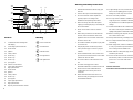
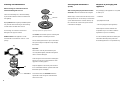
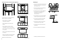
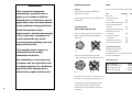
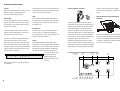
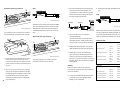
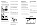
Operating instructions
Gas hob KM 326G
Conversion kit AH 102 C4U
Instructions pour l’utilisation
du dessus de cuisinière au gas KM 326G
Kit de conversion AH 102 C4U
a r t . n r. 7 2 2 . 3 9 2 . 2 0 / T 9 1 7 0 1 B
english
français
page
1 - 27
operating instructions gashob KM 326G
page
1 - 17
converting instructions converting kit AH 102 C4U
page
18 - 27
CDN
page
28 - 55
de cuisinière au gas KM 326G
page
28 - 45
Mode d'emploi du kit de conversion AH 102 C4U
page
46 - 55
USA
CDN
Instructions pour l’utilisation du dessus
Warning
If the information in this
manual is not followed
exactly, a fire or explosion
may result causing damage
to property, personal injury
or death.
* Do not store or use gasoline or
other flammable vapors and liquids
in the vicinity of this or any other
appliance.
* What to do if you smell gas
– Do not try to light any appliance.
– Do not touch any electrical
switch.
– Do not use any phone in your
building.
– Immediately call your gas supplier
using a neighbour’s phone. Follow
the gas supplier‘s instructions.
– If you cannot reach your gas
supplier, call the fire department.
* Installation and service must be
performed by a qualified installer,
service agency or the gas supplier.
1
Warning and safety instructions
2.8
2.7
3
4
1. Read all the instructions before using your
hob unit.
2.6
2.5
2. Use the unit only for its intended purpose.
4.1
2.4
2.2/2.3
2.1
2.
4.2/4.3
4.4
5
3. Do not use the unit unless all parts are
properly in place according to the
installation and operating instructions.
4. Before servicing, disconnect the power
supply by removing the plug or switching off
the circuit breaker.
1
5. Never use the unit to warm or heat the
room.
8
7
6
6. When using an electrical socket near the
burners, make sure that the cable of the
General
1.
control knobs with marking and
Marking
2
2-zone high-speed wok burner
2.1
burner head
2.2
ignition
2.3
safety control
2.4
burner ring
2.5
burner cap
2.6
burner cap
2.7
pan support
2.8
trivet for 2-zone burner
3.
super high-speed burner
4.
high-speed burner
range-top service. Unsuitable containers
may break due to a sudden temperature
change.
17. Position the handle of the container towards
the centre of the range to minimize burns,
spillage and ignition of flammable materials.
18. Before removing pots and pans, be sure to
turn surface unit to “OFF”.
20. Use a deep fat thermometer to prevent
8. Keep all play items stored away from the
or near the unit.
unit to prevent injury to curious or playful
children.
9. Please remember that, in use, burners and
pot racks become hot; therefore ensure that
children do not touch them.
front right burner
16. Use only certain containers suitable for
the burner of the unit.
rear left burner
rear right burner
boiling over, which may cause smoke.
15. Never use moist pot holders.
19. Always heat fat slowly, watching as it heats.
7. Do not allow children to operate or play with
front left burner
hob in case of spitting grease or pans
appliance does not come into contact with
2-zone wok burner
LED display
2.
14. If high settings are used, remain near the
10. Do not store items on the unit when not in
use.
overheating.
21. When frying foods, make sure that the food
is as dry as possible to prevent moisture
from causing hot fat to bubble over.
22. When shallow or deep-fat frying, do not
overfill the pan with oil.
23. Do not use the hob if it is not connected to
the electricity mains or in the event of a
power cut. It is not safe under these
conditions.
11. Do not let cooking grease or other
flammable materials accumulate on the unit.
12. Never leave the unit unattended when
4.1
burner head
cooking with oil or fat. Very hot oil can
4.2
ignition
cause fire.
4.3
safety control
4.4
burner cap
before touching or exposing surface areas
5
pan support
to flammable materials.
6.
super high-speed burner
7.
high-speed burner
8.
drip tray of heat resistant ceramic
Save the instructions.
Leave these instructions with the consumer.
13. Allow sufficient time for the unit to cool
3
Important notes for the user
Gas burners
OFF
– Installation and maintenance should only be
– When a gas cooking appliance is being used,
If a burner blows out, the electronic ignition
carried out by a suitably qualified person
heat and moisture are produced in the area
automatically sparks all burners to relight the
(licensed gas fitter in Canada).
where the appliance is situated. Make sure
flame.
– For safety reasons, this hob should only be
HI
natural ventilation openings or fit a
The flame is lit by means of an electrical ignition
mechanical ventilator (extractor). When the
device. When the burner control is pressed and
not only around the burner, but also the
hob is used for longer periods, extra
turned, a high voltage flows into the electrode
control panel. Therefore ensure that small
ventilation may be needed, such as an open
by the burner. Sparks are created. A spark
children do not touch the hob when it is being
window or a higher setting on the ventilator
ignites the gas to give a flame.
used.
(extractor).
fitted as a built-in appliance.
– Please remember that the hob becomes hot,
XLO
that the area is sufficiently ventilated; open
LO
2-zone super high-speed wok burner
Outer ring
– Push in the burner control knob and turn it to
– When cooking or boiling in large pots or pans,
ensure that there is a minimum distance of
Advice
2˝ (50 mm) between the pot and a heat-
– The safe and efficient use of this appliance
sensitive worktop.
requires that it be regularly serviced by a
After combustion, the hot gases flow
qualified technician; however, the frequency
outwards under the base of the pot and may
of service will depend on usage. Once a year
consequently burn the edge of the worktop if
should suffice.
it is too close.
Lighting and adjusting
the “HI” position. Ignition follows.
– Turn the control to the desired setting once
the burner is alight.
OFF
You may set the knob at any position between
“HI” and “LO”.
HI
– Make sure there is a minimum distance of
5/8˝ (15 mm) between the pot or pan and the
Before starting check
Inner ring
– Push in the burner control knob and turn it to
control panel. Never place a pot on the
control panel.
– When using a cooker hood over the gas hob,
LO
Remove all packaging materials and labels
before using your hob.
high-speed and super high-speed burners
ensure that any burners in use are always
covered with a pot or frying pan. Otherwise,
Check:
A symbol above the control knob indicates
parts of the cooker hood could be damaged
– that the gas is on at the mains;
which burner is being operated.
by the heat and/or flames.
– that the plug is in the wall socket;
– Note that potential hazards may exist with
overhead cabinets.
the “HI” position. Ignition follows.
– that the pan supports are positioned correctly.
– Turn the control to “LO” once the burner is
alight.
– Push in the burner control knob and turn it to
– Push in the burner control knob and turn it to
any position between “LO” and “XLO”.
the “HI” position. Ignition follows.
– Not to be used for space heating. This
instruction is based on safety considerations.
– Turn the control to the desired setting once
the burner is alight. The LED’s indicate the
position of the control knob.
You may set the knob at any position between
“HI” and “LO”.
4
5
How to use gas burners
Cooking in comfort
Pans and pots
Place the pot over the pot support fitted above
frying and pot-roasting
The heat from the burner is transferred via the
the hob.
deep-frying and blanching
pan base. If the base is thick, the heat will take
cooking large quantities
longer to reach the contents, but the base will
stir-frying
have a more uniform temperature. Thin and light
are best done on the super high-speed wok
pans will cause food to burn more easily.
For small pots with a diameter of less then
7˝ (175 mm), the trivet must be used in
combination with the 2-zone wok burner.
Right
Make sure the trivet is securely fixed to the pot
Check to ensure that the burner is burning
stewing and steaming
support.
correctly. The flames should be blue and
cooking standard portions
uniform.
making a roux
Wrong
burner.
To use the gas as efficiently as possible, it is
Push the appropriate control knob, turn it
are best done on the high-speed burner.
counter-clockwise to the setting “HI”.
The high-speed burner is ideal for preparing
best to use a pan with a large diameter.
portions for about 4 people.
If the burner fails to ignite, check that:
– the burner cap is positioned correctly;
making sauces
– the burner is clean and dry.
keeping food hot
cooking through/simmering
To switch off the gas supply to the burner, turn
the control knob, in a clockwise direction, to the
Wrong
are best done on the inner ring of the 2-zone
Right
Wrong
burner.
The tips of the flames are the hottest. If flames
escape around the sides of the pan, a great deal
“OFF” position.
If the flames are not uniform, check to ensure
At the “LO”position, this burner is large enough
When cooking or boiling in large pots or pans,
that the burner cap is properly positioned on the
to cook food through.
ensure that there is a minimum distance of
ring.
of heat is lost.
2˝ (50 mm) between the pot and a heat-sensitive
worktop.
If the flames are irregular and yellow, check to
After combustion, the hot gases flow outwards
ensure that a pressure regulator has been
under the base of the pot and may consequently
installed. Do not use the appliance and inform
burn the edge of the worktop if it is too close.
the installer.
Make sure there is a minimum distance of
Right
5/8˝ (15 mm) between the pot or pan and the
control panel. Never place a pot on the control
Keeping the flame beneath the pan saves time
panel.
and gas and is the safest way to cook.
Cook with the lid on the pan. This can save on
energy by up to 50%.
6
7
Cleaning and maintenance
Cleaning and maintenance
(cont.)
Disposal of packaging and
appliance
After cleaning always dry the burners and the
The packaging of the appliance is recyclable. It
electrodes, otherwise the flame will not ignite.
is made up of:
When using a cooker hood over the hob, ensure
– cardboard
Before cleaning, be certain the burners are
turned off and the grates are cool.
tab
In the event of boiling over, clean immediately,
to prevent the substance which has boiled over
indentation
from igniting.
that any burners in use are always covered with
a pan. Otherwise flames could be drawn up by
Wiping the hob down regularly immediately after
the suction of the cooker hood, parts of which
use prevents dirt from burning on and resulting
could then be damaged.
– polyethylene film (PE)
– CFC-free polystyrene (PS rigid foam)
in stains which are difficult to remove.
Please dispose of these materials in a
For cleaning, use a mixture of water and
Super high-speed burner/ high-speed burner
responsible way in accordance with the
regulations of your local authority.
detergent or all-purpose cleaner.
The burners can be taken apart for cleaning and
Stubborn stains on the appliance can be
put back together as the diagram shows.
Do not submerge hot burner caps in cold water.
sponge.
Your local authority will also be able to give you
information about disposing of disused
removed with a non-abrasive cream or a soft
household appliances in a responsible way.
The quick change in temperature may damage
the enamel.
Important:
The burners must only be lit when they are
correctly fitted together, otherwise the ignition
device could be damaged.
Avoid using too much water when cleaning the
burners. Do not use scouring powder or other
aggressive cleaning agents.
tab
Keep the appliance and vicinity clear and free
from combustible materials, gasoline and other
flammable vapors and liquids.
indentation
From time to time, the electrodes should be
wiped with a well wrung-out cloth and dried
2-zone high-speed wok burner
8
with a clean cloth.
9
Cleaning and maintenance
Cleaning and maintenance
(cont.)
Disposal of packaging and
appliance
After cleaning always dry the burners and the
The packaging of the appliance is recyclable. It
electrodes, otherwise the flame will not ignite.
is made up of:
When using a cooker hood over the hob, ensure
– cardboard
Before cleaning, be certain the burners are
turned off and the grates are cool.
tab
In the event of boiling over, clean immediately,
to prevent the substance which has boiled over
indentation
from igniting.
that any burners in use are always covered with
a pan. Otherwise flames could be drawn up by
Wiping the hob down regularly immediately after
the suction of the cooker hood, parts of which
use prevents dirt from burning on and resulting
could then be damaged.
– polyethylene film (PE)
– CFC-free polystyrene (PS rigid foam)
in stains which are difficult to remove.
Please dispose of these materials in a
For cleaning, use a mixture of water and
Super high-speed burner/ high-speed burner
responsible way in accordance with the
regulations of your local authority.
detergent or all-purpose cleaner.
The burners can be taken apart for cleaning and
Stubborn stains on the appliance can be
put back together as the diagram shows.
Do not submerge hot burner caps in cold water.
sponge.
Your local authority will also be able to give you
information about disposing of disused
removed with a non-abrasive cream or a soft
household appliances in a responsible way.
The quick change in temperature may damage
the enamel.
Important:
The burners must only be lit when they are
correctly fitted together, otherwise the ignition
device could be damaged.
Avoid using too much water when cleaning the
burners. Do not use scouring powder or other
aggressive cleaning agents.
tab
Keep the appliance and vicinity clear and free
from combustible materials, gasoline and other
flammable vapors and liquids.
indentation
From time to time, the electrodes should be
wiped with a well wrung-out cloth and dried
2-zone high-speed wok burner
8
with a clean cloth.
9
Troubleshooting
Electrical circuit diagram
Problem
Cause
Solution
Burner does not burn well
– Burner dirty or moist
– Clean and/or dry the burner
– Not suitable for type of gas
– Check identification plate
SW1
SW2
SW3
SW4
SW5
and if necessary have the
appliance adapted
Ignition sparks but burner
– Burner dirty or moist
com S1
– Burner cap not aligned
properly
Ignition does not spark
A
re-ignition
N
earth
– Clean and/or dry the burner
does not ignite
– Position the cap properly
onto the ring
– The appliance has not yet
been plugged in properly
– Plug in the appliance
properly
S1
S2
S3
S4
S5
LED
12-leds
com S1
LED
9-leds
com S1
LED
9-leds
com S1
LED
9-leds
com S1
LED
spark/sense
5-point gas re-ignitor
120 Vac/60 Hz/3 VA
9-leds
TWO ZONE FRONTLEFT BACK LEFTBACK RIGHT FRONT RIGHT
WOK BURNER
L
N
120V/60HZ
main connecting board
– Ignition is defective
– Phone the Miele Service
Department
If your appliance does not operate as desired,
In the event of any fault on this appliance,
first check if you can solve the problem yourself
please contact:
by using the table above. There is often a simple
– your Miele dealer or
reason for the problem.
– the Miele Service Department,
the address of which is shown on the back
Repairs to the gas and electrical components of
page.
this appliance must only be carried out by a
suitably qualified person (licensed gas fitter in
Please quote the model and serial number of
Canada).
your appliance. You will find both on the data
plate located on the underside of the appliance.
Repairs by unauthorised personnel could be
dangerous and are not covered by the
guarantee.
10
11
Electrical connection
Gas connection
Connect the gas supply to the pressure
The automatic ignition and the safety device
These appliances must be installed with a
regulator using a 1/2” gas line connector
require connect ion to an A.C. single phase
separate shut-off valve and a gas pressure
between the shut-off valve and the pressure
120 V, 60 Hz supply. Fuse rating 6 A.
regulator.
regulator. Flexible harmonica-type stainless
steel pipe is recommended.
The appliances are factory equipped with a
Both shut-off valve and pressure regulator must
power supply cord with molded three prong plug
be easily accessible to the consumer.
For USA only
– ready for connection to an electrically
The gas connection must be made in
grounded socket which complies with your local
The shut-off valve is solely intended to be used
accordance with the local codes, or in absence
electrical codes or with the National Electrical
to shut off the gas supply.
of local codes, with the National Fuel Gas Code
Code ANSI/NFPA No. 70 for the USA or
Electrical Code Part I for Canada.
ANSI Z 223.1.
This appliance and its individual shut-off valve
must be disconnected from the gas supply
Gas pressures for USA
Ensure that the receptacle is positioned so that
piping system during any pressure testing of that
Warning
it is easily accessible when the appliance is
system.
As shown in the above diagram, the regulator
Max. supply pressure:
1/2 psi
included must be used when connecting the
Min. supply pressure:
5˝ water column
built in.
Natural gas
The hob comes equipped for natural gas.
Miele hob.
under the appliance complies with the mains
You should find out details about the type of gas
– Any pipe connections must be made using a
voltage.
and calorific value from your Gas Utility and
thread sealant approved for gas connections.
Max. supply pressure:
1/2 psi
compare this information with the type of gas
Failure to correctly install these items could
Min. supply pressure:
11˝ water column
quoted on the data plate.
lead to a gas leak and subsequent explosion.
Check that the data given on the data plate
Warning:
Liquid propane gas, after converting this
This appliance must be grounded.
appliance with conversion kit number AH102 C4U.
Manifold pressure:
Before using the appliance, check the
Do not cut or remove the grounding prong from
connection with a soapy solution for leaks.
the plug.
Never use a flame of any sort. The interior of
– Do not use any regulator unless it has been
supplied by Miele Appliances.
– natural gas
4˝ water column
– propane gas
10˝ water column
this appliance has been tested by the
manufacturer.
Pressure regulator
A pressure regulator is included with the
appliance.
After installing a gas shut-off valve in an easily
accessible location under the hob, install the
gas pressure regulator to the manifold pipe
using pipe dope on threads of the manifold pipe
12
(see also next page).
13
b. The appliance must be isolated from the gas
For Canada only
Building-in dimensions
supply piping system by closing its individual
The gas connection must be made in
accordance with the local codes, or in absence
manual shut-off valve during any pressure
of local codes, with the current CAN/CA B 149.1
testing of the gas supply piping system at
and .2 Inst.
test pressures equal to or less than 1/2 psi
(3.5 kPa).
Gas pressures for Canada
Manifold pressure:
Warning
– natural gas 4˝ water column
The base of the hob will become hot. The gas
– liquid propane gas 10˝ water column
connection used must comply with the relevant
national and local regulations.
35 7/16" (900 mm)
20 3/16"
(515 mm)
min. 1 3/4"
(45 mm)
3"
(75 mm)
Nominal rating natural gas 4˝ 1)
Burner
high setting
low setting
Important
kW
kW Btu/hr
When the gas hob has been installed, it is
Btu/hr
2.7
9200
0.35 1200
essential to check the main cable is not in
super high-speed burner 3.4
12000
0.45 1500
contact with hot parts of the appliance,
2-zone wok burner
14000
0.17
high-speed burner
4.0
580
19 5/16"
(490 mm)
otherwise temperature damage to the cable
min. 3" (75 mm)
could occur.
Nominal rating LP gas 10˝ with conversion kit 1)
Burner
high setting
low setting
1)
Important
33 7/8" (860 mm)
kW
Btu/hr
kW Btu/hr
This appliance with the orifices as delivered for
Prepare a cut-out in the worktop according to
There may be a wall at the rear and a wall or tall
2.0
7000
0.40 1300
natural gas or LP gas by the manufacturer is
the dimensions given in the diagram above.
units at one side. On the other side, however, no
super high-speed burner
2.7
9200
0.50 2000
suitable for use till 2000 feet. By installation
2-zone wok burner
3.3 11200
0.18 600
above 2000 feet contact your distributor or Miele
high-speed burner
unit or divider may stand higher than the hob.
USA/Canada and ask for a replacement set with
Important
orifices suitable for your altitude.
a. The appliance and its individual shut-off valve
must be disconnected from the gas supply
Change the orifices as written in the instructions
piping system during any pressure testing of
of the manual.
this system at test pressures in excess of
1/2 psi (3.5 kPa).
14
15
Clearance above and around the appliance
Building-in
1. Make the cut-out in the work surface. Ensure
that there is sufficient space allowed at the
min 33 1/4" (845 mm)
sides and at the rear.
min 33 1/14"
(845 mm)
2. Attach the sealing strip to the underside of
min 18"
(460 mm)
min 10"
(254 mm)
the hob and the aeration profile.
min 10"
(254 mm)
3.* Connect the pressure regulator supplied at
the angle-joint, ensuring that they are
positioned correctly. (See also
not allowed
“Gas Connection”.)
glass shield
sealing tape
4. Place the hob in the cut-out. Check that the
air inlets at the back of the hob are clear.
worktop
For safety reasons, ensure that the following
minimum clearences are provided:
5. Secure the hob in position. The brackets
wooden block
clamp underneath the work surface.
burner box
– between adjacent combustible
construction 4” (100 mm).
min. 10"
(254 mm)
6. Make the gas connection. Check the gas
connections with a soapy solution.
– between appliance and rear wall 1 3/8”
(30 mm).
7. Put the plug in the socket (see "Electrical
Connection").
– between appliance and the overhead
not advisable
combustible construction 33 1/4” (845 mm).
8. Test to check that the hob is operational.
– between appliance and front edge of worktop
2 9/16” (65 mm).
– depth of overhead cabinets must not exceed
13” (330 mm).
– between combustible constructions and the
extended cooking surface 18” (460 mm).
* Undertray is positioned on work surface.
Wall strips must be heat-resistant.
16
recommended
17
WARNING
This conversion kit must be
installed by a qualified service
agency in accordance with the
manufacturer's instructions and all
applicable codes and requirements
of the authority having jurisdiction.
If the information in these
instructions is not followed exactly,
a fire, explosion or production of
carbon monoxide may result,
causing property damage, personal
injury or loss of life.
Safety Instructions
Parts
Warning
This conversion kit includes the following parts:
This conversion kit must be installed by a
Part
qualified service agency.
ID number
Number
A
1
090
1
007
1
087
2
075
2
054
1
025
1
Low flame screw burner C
040
2
Low flame screw burner B
036
2
Burner cap
This conversion kit is for use with Miele gas hob
KM 326G only.
Injector wok burner
outer ring
Injector wok burner inner ring
Injector super high-speed
Conversion kit
type number AH 102 C4U
burner C
Injector high-speed burner B
Low flame screw outer
These conversion instructions are to be used
together with the operating and installation
instructions.
wok burner
Low flame screw inner
wok burner
Conversion instructions
The qualified service agency is
responsible for the proper
installation of this kit.
Data plate LP gas 10” W.C.
Right
Wrong
Conversion data plate
This appliance is to be converted to Propane
Check to ensure that the burner is burning
10” W.C. (2.491 kPa) only.
correctly. The flames should be blue and uniform.
The installation is not proper and
complete until the operation of the
converted appliance is checked as
specified in the manufacturer's
instructions supplied with the kit.
Input ratings LP gas
high speed burner . . . . . . . . . . . . . 7000 Btu/hr
super high speed burner . . . . . . . 9200 Btu/hr
wok burner inner ring . . . . . . . . . . 1125 Btu/hr
wok burner outer ring . . . . . . . . . 11200 Btu/hr
Right
Wrong
If the flames are not uniform, check to ensure that
the burner cap is properly positioned on the ring.
If the flames are irregular and yellow, check to
ensure that a pressure regulator has been
18
installed. Do not use the appliance and inform
the installer.
19
Conversion instructions
Caution
Remove the three screws securing the dual ring
Before proceeding with the conversion, shut off
wok burner. Remove the wok burner base plate.
pressures: min. 11" WC (5" WC, natural gas), max.
the gas supply to the appliance prior to
Lift the ceramic tray from the hob.
1/2 psi.
Pressure regulator conversion
purposes. Check gas pressure. Permitted
disconnecting the electrical power.
Note
High speed and super high speed burner
Disassembly
Each regulator shaft is equipped with a black
conversion
Shut off gas supply, disconnect the manifold
ring. This ring may cling to the rubber seal in the
pipe, disconnect the electrical power. Remove
ceramic tray. Check and remove the rings from
The pressure regulator is located on the gas
pan supports, burner heads and burner rings.
the rubber seals.
supply pipe. Unscrew and remove the brass cap
Remove control knobs.
in the centre of the regulator. This gas regulator
For future use
is only adjustable for 4" and 10" gas pressure.
In the event that the hob is built in, undo the
Save the orifices removed from the appliance
There is a blue plastic pin on the inside of the
bracket clamps underneath the work surface.
for future use. For converting this appliance
cap, marked "NAT" and "LP". Pull this pin from the
Lift the hob on to the work surface.
back to Natural gas, follow the instructions and
cap and insert it the other way round. Snap the
Unscrew and replace injectors on the high-
use the numbers in brackets (… ).
pin into the cap. The pin must be positioned as in
speed and super high-speed burners. Replace
the drawing above. The regulator is now
each injector separately. Refer to illustration
Unscrew the venturis on the high-speed and
super high-speed burners using a 20 mm
Igniter
adjusted for propane gas 10" WC. (For natural
“Locations of injectors and minimum adjustment
wrench. Lift and remove the burner rings and
The relationship between the igniter and the
gas 4", turn the pin back.) Screw the cap back on
screws” for screw locations.
burner base plates. Disconnect the wires from
main burners can't be changed. The relationship
the regulator. The pressure regulator is equipped
the ignition plugs. Keep the wire from dropping
in the case of LP gas and natural gas is identical.
with a separate connection for pressure testing
into the undertray by inserting it in one of the
The distance between the igniter and the high
slots in the burner supports.
speed burner and super high speed burner is
± 3.5 mm. For the two zone
high speed burner the
Locations of injectors and minimum adjustment screws
(Natural gas)
LP gas
distance between the
(034)
007
(170)
090
(166)
087
(145)
075
075
(145)
087
(166)
igniter and the inner ring is
± 2.5 mm.
Remove the top five screws in the back of the
hob undertray.
LP gas
(Natural gas)
20
054 025 036 040 036 040
(100)(042) (055)(060) (055)(060)
21
Wok burner outer ring conversion
1. First loosen the 8 mm ring securing the gas
Note
feed pipe. Disconnect the gas pipe. The
B
6. Reattach the gas pipe and tighten the 8 mm
ring.
actual injector is a thin metal cap mounted
A
between the two brass fittings attached to
Note
the left of the wok burner body.
A
B
Outer ring airslot (B)
gaspipe
A
injector
B
Adjust the air slot on the outer ring injector now.
The correct distance for the air slot (B) is 0.083".
Outer ring injector (B)
Inner ring air slot (A)
Slide the brass tube to the prescribed distance
and tighten the holding screw at the rear of the
The wok burner outer ring injector is located on
Inner ring injector
Adjust the air slot on the inner ring injector now.
The slot is adjusted by shifting the metal clip
tube.
2. Two 12 mm wrenches are needed to
the right hand side of the wok burner body (B).
separate the fittings.
Wok burner inner ring conversion
B
A
around the right-hand fitting. Move the clip to
obtain a full opening of the hole (A) in the fitting.
Use one 12 mm wrench to keep the righthand fitting in place, while using the other
Reference table
12 mm wrench to loosen the left-hand fitting.
LP gas
adjustment
3. With the left fitting loosened, unscrew the
right-hand fitting from the wok burner body.
4. Holding them vertical, take both fittings
high-speed burner
super high-speed burner
apart. The metal cap with the injector will
Inner ring injector (A)
1. Unscrew the screw holding the brass tube to
remain on top of the lower fitting. Replace
wok burner inner ring
the injector cap with the injector cap marked
the left of the injector. Access this screw
The inner ring injector is located on the left
007 (034, natural gas) and put the two fittings
from the rear. Slide the brass tube to the left,
hand side of the wok burner body (A).
back together.
wok burner outer ring
injector
screw
0.75 mm
0.36 mm
0.03”
0.014”
0.87 mm
0.40 mm
0.034”
0.016”
0.50 mm
0.25 mm
0.02”
0.01”
0.90 mm
0.54 mm
0.035”
0.021”
but do not insert it into the aluminium tube all
the way.
Warning
natural gas
Make sure that the natural gas injector is
2. Use a 10 mm wrench and unscrew the outer
ring injector. Support the aluminium gas pipe
injector is installed.
feeding the injector by holding it down, while
22
adjustment
removed from the fitting when the propane gas
injector
screw
high-speed burner
1.45 mm
0.55 mm
super high-speed burner
1.66 mm
0.60 mm
turning the wrench. Unscrew the injector
5. Screw the assembled fittings back into the
wok burner inner ring
0.60 mm
0.42 mm
and replace it with the injector marked 090
wok burner body. Carefully tighten both
wok burner outer ring
1.70 mm
1.00 mm
(170, natural gas).
fittings. Do not overtighten.
23
Minimum adjustment screws
1. Lift and remove the small black ring if this is
3. Put the black switches with the light emitting
still on the regulator shaft (see note in
"Disassembly").
Installing appliance
Testing converted appliance
1. Install the appliance according to the
Note
diodes back in place.
4. Attach the label 'This control has been
installation instructions.
This appliance has been internally tested for gas
leakages by the manufacturer.
converted for use with propane gas' to the
2. Lift and remove the square black switches.
Do not disconnect the wires from the
top of the hob undertray. Attach it as close to
the controls as possible.
switches or the light emitting diodes (LED).
5. Fill in the conversion date label and attach
2. Attach the moulding at the rear to the
undertray. Put the hob back in the work
Caution
surface and fasten the bracket clamps
Check converted hob for gas leaks. Check the
underneath the work surface.
connection with a soapy solution. Never use a
flame of any sort.
conversion kit identification label close to the
appliance's original identification plate.
3. Set the gas pressure regulator to a new
pressure of 10” WC (4" WC, natural gas).
Check that the hob functions normally:
Note
Check pressure (see page 21). Permitted
Turn on the gas supply and plug in the power
This concludes conversion. The hob can now be
pressures: minimum 11” WC (5" WC, natural
supply cord.
reassembled.
gas), max. 1/2 psi.
Light each of the burners individually.
When the burner is at low setting, or when the
Assembly
1. Check that the seals are fitted on the ceramic
The wok burner is equipped with two minimum
tray. Put the ceramic tray on the hob. Make
adjustment screws, one for each burner ring.
sure it is correctly positioned on the undertray.
4. Reconnect gas supply, reconnect the manifold
control knob is turned quickly from 'high' to 'low',
pipe, reconnect the electrical power.
the flame should not go out.
When set at 'high', the gas flame must burn with
5. Put the burner heads and pan supports in
Put the black ring around the regulator shaft
place. Make sure the burner heads are
as shown. Press the black rings into the seals.
mounted the right way. Put the burner head
Put the control knobs back.
marked "A" on top of the wok burner.
the center clearly visible.
Locations of injectors and minimum
2. Put the wok burner base plate back in place.
adjustment screws
Fasten the three screws securing the wok
burner base plate.
(Natural gas)
Propane gas
(034)
007
(170)
090
(166)
087
(145)
075
075
(145)
087
(166)
Note
Make sure you replace both minimum
adjustment screws. Put screw 054 (100, natural
gas) on the left, 025 (042, natural gas) on the
right.
3. Connect the wires to the ignition plugs. Put
the high-speed and super high-speed burner
24
Use a small screwdriver and replace each
base plates and burner rings back. Fasten
screw individually.
the high-speed and super high-speed
venturis using a 20 mm wrench.
Propane gas
(Natural gas)
054 025 036 040 036 040
(100)(042) (055)(060) (055)(060)
25
Warranty and service
Technical details
The warranty period is effective from the date of purchase of the appliance.
Model number:
Gas source:
KM 326G
see identification plate
All malfunctions caused by installation errors, improper use or maintenance are excluded from the
Energy source:
guarantee.
Overall wattage, electricity:
Evidence of the date of purchase must be provided upon request, for example through a delivery slip
Total burnerrate
or sales receipt.
Natural gas
120 V - 60 Hz
3 VA
56400 Btu/hr (16.2 kW)
Liquid propane gas
43600 Btu/hr (12.78 kW)
This appliance with the orifices as delivered for
In the event of any fault with this appliance, please contact:
natural gas or LP gas by the manufacturer is
suitable for use till 2000 feet. By installation
your Miele Dealer, or
above 2000 feet contact your distributor or Miele
USA/Canada and ask for a replacement set with
the Miele Service Department, the address of which is shown on the back page.
orifices suitable for your altitude.
When contacting the Service Department, please quote the Model and Serial numbers of your
Change the orifices as written in the instructions
appliance. You will find both on the data plate located on the underside of the appliance.
of the manual.
Where you can find Miele
Miele Appliances, inc.
22 D Worlds Fair drive
Somerset, NJ 08873
Tel. number.: (732) 560-0899
Toll Free:
1-800-843-7231
Fax number: 732-560-9649
Miele Limited
55G East Beaver Creek Rd.
Richmond Hill, Ontario
Canada L4B IE5
26
Phone:
(905) 707-1171
Fax:
(905) 707-0177
27
Warranty and service
Technical details
The warranty period is effective from the date of purchase of the appliance.
Model number:
Gas source:
KM 326G
see identification plate
All malfunctions caused by installation errors, improper use or maintenance are excluded from the
Energy source:
guarantee.
Overall wattage, electricity:
Evidence of the date of purchase must be provided upon request, for example through a delivery slip
Total burnerrate
or sales receipt.
Natural gas
Liquid propane gas
120 V - 60 Hz
3 VA
56400 Btu/hr (16.2 kW)
43600 Btu/hr (12.78 kW)
This appliance with the orifices as delivered for
In the event of any fault with this appliance, please contact:
natural gas or LP gas by the manufacturer is
suitable for use till 2000 feet. By installation
your Miele Dealer, or
above 2000 feet contact your distributor or Miele
USA/Canada and ask for a replacement set with
the Miele Service Department, the address of which is shown on the back page.
orifices suitable for your altitude.
When contacting the Service Department, please quote the Model and Serial numbers of your
Change the orifices as written in the instructions
appliance. You will find both on the data plate located on the underside of the appliance.
of the manual.
.
26
Operating instructions
Gas hob KM 326G
Conversion kit AH 102 C4U
Instructions pour l’utilisation
du dessus de cuisinière au gas KM 326G
Kit de conversion AH 102 C4U
a r t . n r. 7 2 2 . 3 9 2 . 2 0 / T 9 1 7 0 1 B
Operating instructions
Gas hob KM 326G
Conversion kit AH 102 C4U
Instructions pour l’utilisation
du dessus de cuisinière au gas KM 326G
Kit de conversion AH 102 C4U
a r t . n r. 7 2 2 . 3 9 2 . 2 0 / T 9 1 7 0 1 B
Alteration rights reserved / 2503
This paper is made from cellulose bleached without the use of chlorine.
01