1
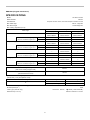
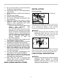
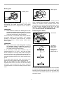
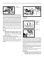
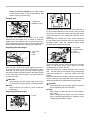
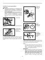
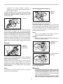
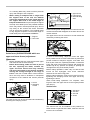
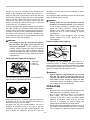
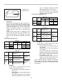
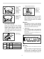
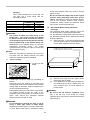
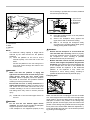
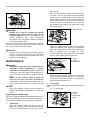
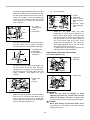
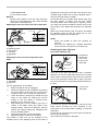
ENGLISH (Original instructions)
INSTRUCTION MANUAL
Slide Compound Miter Saw
LS1216
LS1216L
010049
DOUBLE INSULATION
IMPORTANT: Read Before Using.
1
ENGLISH (Original instructions)
SPECIFICATIONS
Model
LS1216/ LS1216L
Blade diameter
305 mm
European countries: 30 mm, other than European countries: 25.4 mm
Hole diameter
Max. Miter angle
Left 52° , Right 60°
Max. Bevel angle
Left and Right 45°
Max. Cutting capacities (H x W)
Bevel angle
Miter angle
0°
Thickness of wood facing on guide
fence for increased height of cut
44mm×382mm
69mm×363mm
102mm×363mm
54mm×363mm
115mm×300mm
61mm×290mm
60mm
―
120mm×250mm
―
59mm×268mm
87mm×268mm
44mm×268mm
69mm×255mm
102mm×255mm
54mm×255mm
30mm
―
115mm×202mm
―
45mm
―
120mm×172mm
―
―
87mm×233mm
―
―
102mm×220mm
―
25mm
―
115mm×178mm
―
35mm
―
120mm×155mm
―
―
87mm×185mm
―
―
102mm×178mm
―
25mm
―
115mm×140mm
―
35mm
―
120mm×122mm
―
60°(right)
Thickness of wood facing on guide
fence for increased height of cut
45°(right)
87mm×382mm
78mm×290 mm
52°(left and right)
Thickness of wood facing on guide
fence for increased height of cut
0°
59mm×382mm
35mm
45°(left and right)
Thickness of wood facing on guide
fence for increased height of cut
45°(left)
Special Max. Cutting capacities
Crown molding 45 ゚ type
203 mm
(with Crown molding stopper used)
Base board (H)
165 mm
(with Horizontal vise used)
Special Max Width Cutting Capacities
(with 38 mm (1-1/2") thick platform used)
Bevel angle
0°
Miter angle
Max. cutting
0°
416 mm
45° (Left and right)
292 mm
Refer to OPERATION for the cutting procedure.
No load speed (min-1)
3200
Laser Type (LS1216L only)
Red Laser 650 nm,
Dimensions (L x W x H)
1.6mW ( Laser Class 2M )
806 mm x 640 mm x 721 mm
2
Net weight
For all countries other than European countries
LS1216…26.3 kg
LS1216L …26.4 kg
For European countries
LS1216…26.5 kg
LS1216L…26.6 kg
/II
Safety class
• Due to our continuing programme of research and development, the specifications herein are subject to change without notice.
• Note: Specifications may differ from country to country.
• Weight according to EPTA-Procedure 1/2003
END210-6
ENF002-1
Power supply
The tool should be connected only to a power supply of
the same voltage as indicated on the nameplate, and
can only be operated on single-phase AC supply. They
are double-insulated in accordance with European
Standard and can, therefore, also be used from sockets
without earth wire.
Symbols
The following show the symbols used for the equipment.
Be sure that you understand their meaning before use.
・ Read instruction manual.
・
DOUBLE INSULATION
・
To avoid injury from flying debris, keep
holding the saw head down, after
making cuts, until the blade has come
to a complete stop.
・
When performing slide cut, first pull
carriage fully and press down handle,
then push carriage toward the guide
fence.
Do not place hand or fingers close to
the blade.
Never look into the laser beam. Direct
laser beam may injure your eyes.
Only for EU countries
Do not dispose of electric equipment
together with household waste material!
In observance of European Directive
2002/96/EC on waste electric and
electronic
equipment
and
its
implementation in accordance with
national law, electric equipment that
have reached the end of their life must
be collected separately and returned to
an
environmentally
compatible
recycling facility.
・
・
・
ENG102-3
Noise
The typical A-weighted noise level determined according
to EN61029:
Sound pressure level (LpA) : 88 dB(A)
Sound power level (LWA) : 101 dB(A)
Uncertainty (K) : 3 dB(A)
Wear ear protection
ENG238-2
Vibration
The vibration emission value determined according to
EN61029 :
Vibration emission (ah) : 2.5 m/s2 or less
Uncertainty (K) : 1.5 m/s2
The declared vibration emission value has been
measured in accordance with a standard test method
and may be used for comparing one tool with another.
The declared vibration emission value may also be used
in a preliminary assessment of exposure.
WARNING:
•
•
ENE006-1
Intended use
The tool is intended for accurate straight and miter
cutting in wood. With appropriate saw blades, aluminum
can also be sawed.
3
The vibration emission during actual use of the
power tool can differ from the declared emission
value depending on the ways in which the tool is
used.
Be sure to identify safety measures to protect the
operator that are based on an estimation of
exposure in the actual conditions of use (taking
account of all parts of the operating cycle such as
the times when the tool is switched off and when it
is running idle in addition to the trigger time).
ENH003-12
5.
We Makita Corporation as the responsible
manufacturer declare that the following Makita
machine(s):
Designation of Machine:
Slide Compound Miter Saw
6.
For European countries only
EC Declaration of Conformity
7.
Model No./ Type: LS1216, LS1216L,
are of series production and
Conforms to the following European Directives:
2006/42/EC
And are manufactured in accordance with the following
standards or standardised documents:
EN61029
The technical documentation is kept by our authorised
representative in Europe who is:
Makita International Europe Ltd,
Michigan, Drive, Tongwell,
Milton Keynes, MK15 8JD, England
8.
9.
10.
30th January 2009
11.
000230
Tomoyasu Kato
Director
Makita Corporation
3-11-8, Sumiyoshi-cho,
Anjo, Aichi, JAPAN
12.
ENA001-2
13.
SAFETY INSTRUCTIONS
WARNING! When using electric tools, basic safety
precautions, including the following, should always
be followed to reduce the risk of fire, electric shock
and personal injury. Read all these instructions
before operating this product and save these
instructions.
14.
For safe operations:
1.
2.
3.
4.
Keep work area clean.
Cluttered areas and benches invite injuries.
Consider work area environment.
Do not expose power tools to rain. Do not use
power tools in damp or wet locations. Keep work
area well lit. Do not use power tools where there is
risk to cause fire or explosion.
Guard against electric shock.
Avoid body contact with earthed or grounded
surfaces
(e.g.
pipes,
radiators,
ranges,
refrigerators).
Keep children away.
Do not let visitors touch the tool or extension cord.
All visitors should be kept away from work area.
15.
16.
17.
4
Store idle tools.
When not in use, tools should be stored in a dry,
high or locked up place, out of reach of children.
Do not force the tool.
It will do the job better and safer at the rate for
which it was intended.
Use the right tool.
Do not force small tools or attachments to do the
job of a heavy duty tool. Do not use tools for
purposes not intended; for example, do not use
circular saws to cut tree limbs or logs.
Dress properly.
Do not wear loose clothing or jewellery, they can
be caught in moving parts. Rubber gloves and
non-skid footwear are recommended when
working outdoors. Wear protecting hair covering
to contain long hair.
Use safety glasses and hearing protection.
Also use face or dust mask if the cutting operation
is dusty.
Connect dust extraction equipment.
If devices are provided for the connection of dust
extraction and collection facilities ensure these
are connected and properly used.
Do not abuse the cord.
Never carry the tool by the cord or yank it to
disconnect it from the socket. Keep the cord away
from heat, oil and sharp edges.
Secure work.
Use clamps or a vice to hold the work. It is safer
than using your hand and it frees both hands to
operate the tool.
Do not overreach.
Keep proper footing and balance at all times.
Maintain tools with care.
Keep cutting tools sharp and clean for better and
safer performance. Follow instructions for
lubrication and changing accessories. Inspect tool
cord periodically and if damaged have it repaired
by an authorized service facility. Inspect extension
cords periodically and replace, if damaged. Keep
handles dry, clean and free from oil and grease.
Disconnect tools.
When not in use, before servicing and when
changing accessories such as blades, bits and
cutters.
Remove adjusting keys and wrenches.
Form the habit of checking to see that keys and
adjusting wrenches are removed from the tool
before turning it on.
Avoid unintentional starting.
Do not carry a plugged-in tool with a finger on the
switch. Ensure switch is off when plugging in.
18.
19.
20.
21.
22.
7.
Use outdoor extension leads.
When tool is used outdoors, use only extension
cords intended for outdoor use.
Stay alert.
Watch what you are doing. Use common sense.
Do not operate tool when you are tired.
Check damaged parts.
Before further use of the tool, a guard or other part
that is damaged should be carefully checked to
determine that it will operate properly and perform
its intended function. Check for alignment of
moving parts, free running of moving parts,
breakage of parts, mounting and any other
conditions that may affect its operation. A guard or
other part that is damaged should be properly
repaired or replaced by an authorized service
center unless otherwise indicated in this
instruction manual. Have defective switches
replaced by an authorized service facility. Do not
use the tool if the switch does not turn it on and
off.
Warning.
The use of any accessory or attachment, other
than those recommended in this instruction
manual or the catalog, may present a risk of
personal injury.
Have your tool repaired by a qualified person.
This electric tool is in accordance with the relevant
safety requirements. Repairs should only be
carried out by qualified persons using original
spare parts, otherwise this may result in
considerable danger to the user.
8.
9.
10.
11.
12.
13.
14.
15.
16.
17.
18.
ENB034-6
19.
ADDITIONAL SAFETY RULES
FOR TOOL
1.
2.
3.
4.
5.
6.
20.
Wear eye protection.
Keep hands out of path of saw blade. Avoid
contact with any coasting blade. It can still
cause severe injury.
Do not operate saw without guards in place.
Check blade guard for proper closing before
each use. Do not operate saw if blade guard
does not move freely and close instantly.
Never clamp or tie the blade guard into the
open position.
Do not perform any operation freehand. The
workpiece must be secured firmly against the turn
base and guide fence with the vise during all
operations. Never use your hand to secure the
workpiece.
Never reach around saw blade.
Turn off tool and wait for saw blade to stop
before moving workpiece or changing
settings.
21.
22.
23.
24.
25.
26.
5
Unplug tool before changing blade or
servicing.
Always secure all moving portions before
carrying the tool.
Stopper pin which locks the cutter head down
is for carrying and storage purposes only and
not for any cutting operations.
Do not use the tool in the presence of
flammable liquids or gases. The electrical
operation of the tool could create an explosion
and fire when exposed to flammable liquids or
gases.
Check the blade carefully for cracks or
damage before operation.
Replace
cracked
or
damaged
blade
immediately.
Use only flanges specified for this tool.
Be careful not to damage the arbor, flanges
(especially the installing surface) or bolt.
Damage to these parts could result in blade
breakage.
Make sure that the turn base is properly
secured so it will not move during operation.
For your safety, remove the chips, small
pieces, etc. from the table top before
operation.
Avoid cutting nails. Inspect for and remove all
nails from the workpiece before operation.
Make sure the shaft lock is released before the
switch is turned on.
Be sure that the blade does not contact the
turn base in the lowest position.
Hold the handle firmly. Be aware that the saw
moves up or down slightly during start-up and
stopping.
Make sure the blade is not contacting the
workpiece before the switch is turned on.
Before using the tool on an actual workpiece,
let it run for a while. Watch for vibration or
wobbling that could indicate poor installation
or a poorly balanced blade.
Wait until the blade attains full speed before
cutting.
Stop operation immediately if you notice
anything abnormal.
Do not attempt to lock the trigger in the on
position.
Be alert at all times, especially during
repetitive, monotonous operations. Do not be
lulled into a false sense of security. Blades are
extremely unforgiving.
Always use accessories recommended in this
manual. Use of improper accessories such as
abrasive wheels may cause an injury.
27.
28.
29.
30.
31.
32.
33.
34.
35.
36.
37.
38.
39.
40.
Do not use the saw to cut other than wood,
aluminum or similar materials.
Connect miter saws to a dust collecting device
when sawing.
Select saw blades in relation to the material to
be cut.
Take care when slotting.
Replace the kerf board when worn.
Do not use saw blades manufactured from
high speed steel.
Some dust created from operation contains
chemicals known to cause cancer, birth
defects or other reproductive harm. Some
examples of these chemicals are:
•
lead from lead-based-painted material and,
•
arsenic
and
chromium
from
chemically-treated lumber.
Your risk from these exposures varies,
depending on how often you do this type
of work. To reduce your exposure to these
chemicals: work in a well ventilated area
and work with approved safety equipment,
such as those dust masks that are
specially
designed
to
filter
out
microscopic particles.
To reduce the emitted noise, always be sure
that the blade is sharp and clean.
The operator is adequately trained in the use,
adjustment and operation of the machine.
Use correctly sharpened saw blades. Observe
the maximum speed marked on the saw blade.
Refrain from removing any cut-offs or other
parts of the workpiece from the cutting area
whilst the tool is running and the saw head is
not in the rest position.
Use only saw blades recommended by the
manufacturer which conform to EN847-1.
Wear gloves for handling saw blade (saw
blades shall be carried in a holder wherever
practicable) and rough material.
When fitted with laser, no exchange with
different type of laser is permitted. Repairs
shall only be carried out correctly.
INSTALLATION
Bench mounting
1
1. Stopper pin
009483
When the tool is shipped, the handle is locked in the
lowered position by the stopper pin. Release the stopper
pin by simultaneously applying a slight downward
pressure on the handle and pulling the stopper pin.
•
WARNING:
Ensure that the tool will not move on the
supporting surface. Movement of the miter saw
on the supporting surface while cutting may result
in loss of control and serious personal injury.
1. Hex bolts
1
1
1
010593
This tool should be bolted with four bolts to a level and
stable surface using the bolt holes provided in the tool's
base. This will help prevent tipping and possible injury.
FUNCTIONAL DESCRIPTION
•
SAVE THESE INSTRUCTIONS.
6
WARNING:
Always be sure that the tool is switched off and
unplugged before adjusting or checking
function on the tool. Failure to switch off and
unplug the tool may result in serious personal
injury from accidental start-up.
Blade guard
1. Blade guard
1. Blade guard
1
1
009486
With the blade guard so positioned, cleaning can be
more completely and efficiently accomplished. When
cleaning is complete reverse procedure above and
secure bolt. Do not remove spring holding blade guard.
If guard becomes damaged through age or UV light
exposure, contact a Makita service center for a new
guard. DO NOT DEFEAT OR REMOVE GUARD.
009485
When lowering the handle, the blade guard rises
automatically. The blade guard returns to its original
position when the cut is completed and the handle is
raised.
WARNING:
Never defeat or remove the blade guard or the
spring which attaches to the guard. An exposed
blade as a result of defeated guarding may result
in serious personal injury during operation.
In the interest of your personal safety, always maintain
the blade guard in good condition. Any irregular
operation of the blade guard should be corrected
immediately. Check to assure spring loaded return
action of guard.
Positioning kerf board
•
1. Kerf board
1
WARNING:
•
Never use the tool if the blade guard or spring
are damaged, faulty or removed. Operation of
the tool with a damaged, faulty or removed guard
may result in serious personal injury.
If the see-through blade guard becomes dirty, or
sawdust adheres to it in such a way that the blade
and/or workpiece is no longer easily visible, unplug the
saw and clean the guard carefully with a damp cloth. Do
not use solvents or any petroleum-based cleaners on
the plastic guard because this may cause damage to the
guard.
If the blade guard becomes dirty and needs to be
cleaned for proper operation follow the steps below:
With the tool switched off and unplugged, use the
supplied socket wrench to loosen the hex bolt holding
the center cover. Loosen the hex bolt by turning it
counterclockwise and raise the blade guard and center
cover.
009488
1
2
4
3
1. Saw blade
2. Blade teeth
3. Kerf board
4. Left bevel cut
5. Straight cut
6. Right bevel cut
5
6
001538
This tool is provided with the kerf boards in the turn base
to minimize tearing on the exit side of a cut. The kerf
boards are factory adjusted so that the saw blade does
not contact the kerf boards. Before use, adjust the kerf
boards as follows:
7
1. Lock lever
2. Locking screw
1
2
3
1
4
009496
First, unplug the tool. Loosen all the screws (3 each on
left and right) securing the kerf boards. Re-tighten them
only to the extent that the kerf boards can still be easily
moved by hand. Lower the handle fully and push in the
stopper pin to lock the handle in the lowered position.
Loosen the locking screw counterclockwise which
secures the upper slide poles and also push forward the
lock lever which secures the lower slide poles. Pull the
carriage toward you fully. Adjust the kerf boards so that
the kerf boards just contact the sides of the blade teeth.
Tighten the front screws (do not tighten firmly). Push the
carriage toward the guide fence fully and adjust the kerf
boards so that the kerf boards just contact the sides of
blade teeth. Tighten the rear screws (do not tighten
firmly).
After adjusting the kerf boards, release the stopper pin
and raise the handle. Then tighten all the screws
securely.
NOTICE:
•
After setting the bevel angle ensure that the
kerf boards are adjusted properly. Correct
adjustment of the kerf boards will help provide
proper support of the workpiece minimizing
workpiece tear out.
2
1. Adjusting bolt
2. Turn base
3. Stopper lever
4. Slide pipe
009518
2
1
3
1. Top surface of
turn base
2. Periphery of
blade
3. Guide fence
009737
1. Stopper lever
1
Maintaining maximum cutting capacity
009736
This tool is factory adjusted to provide the maximum
cutting capacity for a 305mm saw blade.
Unplug the tool before any adjustment is attempted.
When installing a new blade, always check the lower
limit position of the blade and if necessary, adjust it as
follows:
First, unplug the tool. Lower the stopper lever to position
the saw blade as shown in the figure. Push the carriage
toward the guide fence fully and lower the handle
completely. Use the socket wrench to turn the adjusting
bolt until the periphery of the blade extends slightly
below the top surface of the turn base at the point where
the front face of the guide fence meets the top surface of
the turn base.
With the tool unplugged, rotate the blade by hand while
holding the handle all the way down to be sure that the
blade does not contact any part of the lower base.
Re-adjust slightly, if necessary.
After adjustment, always return the stopper lever to the
original position by turning it counterclockwise.
•
8
WARNING:
After installing a new blade and with the tool
unplugged, always be sure that the blade does
not contact any part of the lower base when the
handle is lowered completely. If a blade makes
contact with the base it may cause kickback and
result in serious personal injury.
1. Latch lever
1
Stopper arm
1. Stopper arm
2. Adjusting screw
2
1
010322
To adjust the bevel angle, loosen the lever at the rear of
the tool counterclockwise. Push the latch lever forward
as shown in the figure fully while supporting the weight
of the saw head so as to release the pressure on the
lock pin.
When tilting the carriage to the right, tilt the carriage to
the left slightly after loosening the lever and press the
releasing button. With the releasing button being
pressed, tilt the carriage to the right.
009487
The lower limit position of the blade can be easily
adjusted with the stopper arm. To adjust it, rotate the
stopper arm in the direction of the arrow as shown in the
figure. Adjust the adjusting screw so that the blade stops
at the desired position when lowering the handle fully.
Adjusting the miter angle
4
1. Lock lever
2. Grip
3. Cam
1
3
1. Scale plate
2. Release button
3. Pointer
4. Latch lever
2
2
1
009513
3
Tilt the saw blade until the pointer points to the desired
angle on the bevel scale. Then tighten the lever
clockwise firmly to secure the arm.
When the latch lever is pulled towards the front of the
saw, the saw blade can be locked using positive stops
at the right and left 22.5 ° and 33.9 ° angle to the base
surface.
When the latch lever is pushed to the back of the saw as
shown in the figure, the saw blade can be locked at any
desired angle within the specified bevel angle range.
009517
Push the grip so that the cams engages and turn it
clockwise until it stops. Turn the turn base while pressing
down the lock lever. When you have moved the grip to
the position where the pointer points to the desired angle
on the miter scale, turn the grip 90° counterclockwise to
lock the turn base.
CAUTION:
After changing the miter angle, always secure the
turn base by turning the grip 90° counterclockwise.
NOTICE:
•
When turning the turn base, be sure to raise the
handle fully.
•
CAUTION:
After changing the bevel angle, always secure the
arm by tightening the lever clockwise.
NOTICE:
•
When tilting the saw blade be sure the handle is
fully raised.
•
When changing bevel angles, be sure to position
the kerf boards appropriately as explained in the
"Positioning kerf boards" section.
•
Adjusting the bevel angle
1. Lever
1
009489
9
To prevent the switch trigger from being accidentally
pulled, a lock-off button is provided. To start the tool,
press in the lock-off button and pull the switch trigger.
Release the switch trigger to stop.
Slide lock adjustment
1. Lock lever
2. Locking screw
WARNING:
Before plugging in the tool, always check to
see that the switch trigger actuates properly
and returns to the "OFF" position when
released. Do not pull the switch trigger hard
without pressing in the lock-off button. This
can cause switch breakage. Operating a tool with
a switch that does not actuate properly can lead to
loss of control and serious personal injury.
A hole is provided in the switch trigger for insertion of
padlock to lock the tool off.
•
2
1
009496
To lock the lower slide pole, pull the lock lever towards
the front of the saw.
To lock the upper slide pole, turn the locking screw
clockwise.
Switch action
For European countries
•
1. Lock-off button
2. Switch trigger
3. Lever
4. Hole for padlock
1
2
3
•
4
009886
To prevent the switch trigger from being accidentally
pulled, a lock-off button is provided. To start the tool, push
the lever to the left, press in the lock-off button and then
pull the switch trigger. Release the switch trigger to stop.
•
WARNING:
Before plugging in the tool, always check to
see that the switch trigger actuates properly
and returns to the "OFF" position when
released. Do not pull the switch trigger hard
without pressing in the lock-off button. This
can cause switch breakage. Operating a tool with
a switch that does not actuate properly can lead to
loss of control and serious personal injury.
A hole is provided in the switch trigger for insertion of
padlock to lock the tool off.
For all countries other than European countries
•
•
WARNING:
Do not use a lock with a shank or cable any
smaller than 6.35 mm in diameter. A smaller
shank or cable may not properly lock the tool in the
off position and unintentional operation may occur
resulting in serious personal injury.
NEVER use tool without a fully operative switch
trigger. Any tool with an inoperative switch is
HIGHLY DANGEROUS and must be repaired
before further usage or serious personal injury may
occur.
For your safety, this tool is equipped with a lock-off
button which prevents the tool from unintended
starting. NEVER use the tool if it runs when you
simply pull the switch trigger without pressing the
lock-off button. A switch in need of repair may
result in unintentional operation and serious
personal injury. Return tool to a Makita service
center for proper repairs BEFORE further usage.
NEVER defeat the lock-off button by taping down
or some other means. A switch with a defeated
lock-off button may result in unintentional operation
and serious personal injury.
Electronic function
Constant speed control
•
1. Switch trigger
2. Lock-off button
3. Hole for padlock
The tool is provided with an electronic speed
control which helps maintain a constant blade
rotation speed even under load. A constant blade
rotation speed will result in a very smooth cut.
Soft start feature
•
1
3
2
009491
10
This function allows the smooth start-up of the tool
by limiting the start-up torque.
Aligning the laser line
Laser beam action
For models LS1216L only
A
B
1. Switch for laser
1
009494
Laser line can be shifted to either the left or right side of
the blade according to the applications of cutting. Refer
to explanation titled "Laser beam action" regarding its
shifting method.
009492
CAUTION:
Never look into the laser beam. Direct laser beam
may injure your eyes.
•
LASER RADIATION, DO NOT STARE INTO THE
BEAM OR VIEW DIRECTLY WITH OPTICAL
INSTRUMENTS, CLASS 2M LASER PRODUCT.
To turn on the laser beam, press the upper position (I) of
the switch. To turn off the laser beam, press the lower
position (0) of the switch.
Laser line can be shifted to either the left or right side of
the saw blade by adjusting the adjusting screw as
follows.
•
NOTE:
•
Use wood facing against the guide fence when
aligning the cutting line with the laser line at the
side of guide fence in compound cutting (bevel
angle 45 degrees and miter angle right 45
degrees).
A) When you obtain the correct size on the left side of
workpiece
•
Shift the laser line to the left of the blade.
B) When you obtain the correct size on the right side of
workpiece
•
Shift the laser line to the right of the blade.
Align the cutting line on your workpiece with the laser
line.
1. Adjusting screw
1
ASSEMBLY
009493
•
1.
Loosen the adjusting screw by turning it
counterclockwise.
2.
With the adjusting screw loosened, slide the
adjusting screw to the right or left as far as it goes.
3.
Tighten the adjusting screw firmly at the position
where it stops sliding.
Laser line is factory adjusted so that it is positioned
within 1 mm from the side surface of the blade (cutting
position).
WARNING:
Always be sure that the tool is switched off and
unplugged before working on the tool. Failure to
switch off and unplug the tool may result in serious
personal injury.
Socket wrench storage
1. Wrench holder
2. Socket wrench
1
NOTE:
•
When laser line appears dim and hard to see
because of direct sunlight, relocate the work area
to a place where there is less direct sunlight.
2
009495
The socket wrench is stored as shown in the figure.
When the socket wrench is needed it can be pulled out
of the wrench holder. After using the socket wrench it
can be stored by returning it to the wrench holder.
11
Installing or removing saw blade
•
•
WARNING:
Always be sure that the tool is switched off and
unplugged before installing or removing the
blade. Accidental start up of the tool may result in
serious personal injury.
Use only the Makita socket wrench provided to
install or remove the blade.Failure to use the
wrench may result in overtightening or insufficient
tightening of the hex bolt and serious personal
injury.
1. Shaft lock
2. Blade case
3. Hex bolt
1
2
1. Stopper pin
1
3
009498
1
2
009483
Lock the handle in the raised position by pushing in the
stopper pin.
1
2
3
1. Center cover
2. Socket wrench
3. Hex bolt
4. Blade guard
3
1. Arrow
2. Arrow
3. Blade case
4. Saw blade
4
009500
1
2
1. Hex bolt
2. Outer flange
3. Saw blade
4. Inner flange
5. Spindle
6. Ring
3
6
4
009497
To remove the blade, use the socket wrench to loosen
the hex bolt holding the center cover by turning it
counterclockwise. Raise the blade guard and center
cover.
4
5
009925
Press the shaft lock to lock the spindle and use the
socket wrench to loosen the hex bolt clockwise. Then
remove the hex bolt, outer flange and blade.
NOTE:
•
If the inner flange is removed be sure to install it on
the spindle with its protrusion facing away from the
blade. If the flange is installed incorrectly the
flange will rub against the machine.
•
12
WARNING:
Before mounting the blade onto the spindle,
always be sure that the correct ring for the
blade's arbor hole you intend to use is installed
between the inner and the outer flanges. Use of
the incorrect arbor hole ring may result in the
improper mounting of the blade causing blade
movement and severe vibration resulting in
possible loss of control during operation and in
serious personal injury.
To install the blade, mount it carefully onto the spindle,
making sure that the direction of the arrow on the
surface of the blade matches the direction of the arrow
on the blade case.
Dust box (Optional accessory)
1. Dust box
2. Cover
3. Button
1
1. Hex bolt
3
2
006793
Insert the dust box into the dust nozzle.
Empty the dust box when necessary.
To empty the dust box, open the cover by pushing the
button and dispose of the sawdust. Return the cover to
the original position and lock it in place. Dust box can
easily be removed by pulling it out while turning it near
the dust nozzle on the tool.
1
009524
Install the outer flange and hex bolt, and then use the
socket wrench to tighten the hex bolt (left-handed)
securely counterclockwise while pressing the shaft lock.
Return the blade guard and center cover to its original
position. Then tighten the hex bolt clockwise to secure
the center cover. Release the handle from the raised
position by pulling the stopper pin. Lower the handle to
make sure that the blade guard moves properly. Make
sure the shaft lock has released spindle before making
cut.
NOTE:
•
If you connect a Makita vacuum cleaner to this tool,
cleaner operations can be performed.
NOTICE:
•
Empty the dust box before collected sawdust level
reaches the cylinder section.
1
1. Cylinder section
2. Dust box
3. Sawdust
1
1. Cylinder section
2. Dust box
Dust bag
2
1
3
1. Fastener
2. Dust bag
3. Dust nozzle
2
3
010592
009501
The use of the dust bag makes cutting operations
cleaner and dust collection easier. To attach the dust
bag, fit it onto the dust nozzle.
When the dust bag is about half full, remove the dust
bag from the tool and pull the fastener out. Empty the
dust bag of its contents, tapping it lightly so as to remove
particles adhering to the insides which might hamper
further collection.
2
010591
Securing workpiece
NOTE:
If you connect a vacuum cleaner to your saw, cleaner
operations can be performed.
•
•
13
WARNING:
It is extremely important to always secure the
workpiece correctly with the proper type of vise
or crown molding stoppers. Failure to do so may
result in serious personal injury and cause damage
to the tool and/or the workpiece.
After a cutting operation do not raise the blade
until it has come to a complete stop. The raising
of a coasting blade may result in serious personal
injury and damage to the workpiece.
When cutting a workpiece that is longer than
the support base of the saw, the material
should be supported the entire length beyond
the support base and at the same height to
keep the material level. Proper workpiece support
will help avoid blade pinch and possible kickback
which may result in serious personal injury. Do not
rely solely on the vertical vise and/or horizontal
vise to secure the workpiece. Thin material tends
to sag. Support workpiece over its entire length to
avoid blade pinch and possible KICKBACK.
•
1
1
3
010594
A red indicating area will appear as the lower fences are
moved inward and will disappear as the lower fences are
moved outward.
The upper fences can be removed or moved inward and
outward by loosening the levers.
1. Support
2. Turn base
2
1. Upper fence
2. Lower fence
3. Red indicating
area
2
001549
Guide fence (SLIDING FENCES which are
upper and lower fences) adjustment
•
•
009611
In case of bevel-cutting, adjust the lower and upper
fence positions to be as close to the blade as practical to
provide maximum workpiece support, and make sure
that no part of the tool, especially the blade, contacts the
lower and upper fences when lowering and raising the
handle fully at any position and pulling or pushing the
carriage all the way at the lowest position.
Before cutting operations, make a dry run with the saw
turned off and unplugged, then check clearance
between fences and moving parts.
Before cutting operations, firmly secure lower fences by
tightening the clamping screws and upper fences by
tightening the levers.
When bevel-cutting operations are complete, don't
forget to return the upper fences to the original position
and return it.
WARNING:
Before operating the tool, make sure that the upper
and lower fences are secured firmly.
Before bevel-cutting, make sure that no part of
the tool, especially the blade, contacts the
upper and lower fences when fully lowering
and raising the handle in any position and while
moving the carriage through its full range of
travel. If the tool or blade makes contact with the
fence this may result in kickback or unexpected
movement of the material and serious personal
injury.
1. Levers
2. Clamping
screws
1
Vertical vise
4
1
2
1. Vise knob
2. Vise arm
3. Vise rod
4. Screw
009508
The lower fences can be moved inward and outward by
loosening the clamping screws.
3
2
009502
The vertical vise can be installed in two positions on
either the left or right side of the base. Insert the vise rod
into the hole in the base.
14
Position the vise arm according to the thickness and
shape of the workpiece and secure the vise arm by
tightening the screw. If the screw to secure the vise arm
contacts the carriage, install the screw on the opposite
side of vise arm. Make sure that no part of the tool
contacts the vise when lowering the handle fully and
pulling or pushing the carriage all the way. If some part
contacts the vise, re-position the vise.
Press the workpiece flat against the guide fence and the
turn base. Position the workpiece at the desired cutting
position and secure it firmly by tightening the vise knob.
Turning the vise knob to 90° counterclockwise allows the
vise knob to be moved up and down, facilitating the
quick setting of workpiece. To secure the workpiece after
setting, turn the vise knob clockwise.
•
clockwise. Then turn the vise knob clockwise to secure
the workpiece.
The maximum width of workpiece which can be secured
by the horizontal vise is 215 mm.
•
•
WARNING:
The workpiece must be secured firmly against
the turn base and guide fence with the vise
during all operations. If the workpiece is not
properly secured against the fence the material
may move during the cutting operation causing
possible damage to the blade, causing the material
to be thrown and loss of control resulting in serious
personal injury.
WARNING:
Always rotate the vise nut clockwise until the
workpiece is properly secured. If the workpiece
is not properly secured the material may move
during the cutting operation causing possible
damage to the blade, causing the material to be
thrown and loss of control resulting in serious
personal injury.
When cutting a thin workpiece, such as base
boards, against the fence, always use the
horizontal vise.
Holders (Optional accessory)
1. Holder
2. Screw
1
Horizontal vise (optional accessory)
2
009607
The holders can be installed on either side as a
convenient means of holding workpieces horizontally.
Slip the holder rods into the holes in the base and adjust
their length according to the workpiece to be held. Then
tighten the holders securely with the screws.
1. Vise plate
2. Vise nut
3. Vise knob
1
3
2
•
009606
The horizontal vise can be installed in two positions on
either the left or right side of the base.
WARNING:
Always support a long workpiece so it is level
with the top surface of the turn base for an
accurate cut and to prevent dangerous loss of
tool control. Proper workpiece support will help
avoid blade pinch and possible kickback which
may result in serious personal injury.
OPERATION
NOTICE:
•
Before use, be sure to release the handle from the
lowered position by pulling the stopper pin.
•
Do not apply excessive pressure on the handle
when cutting. Too much force may result in
overload of the motor and/or decreased cutting
efficiency. Push down handle with only as much
force as is necessary for smooth cutting and
without significant decrease in blade speed.
•
Gently press down the handle to perform the cut. If
the handle is pressed down with force or if lateral
force is applied, the blade will vibrate and leave a
005232
When performing 15° or greater miter cuts, install the
horizontal vise on the side opposite the direction in
which the turn base is to be turned.
By flipping the vise nut counterclockwise, the vise is
released, and rapidly moves in and out. To grip the
workpiece, push the vise knob forward until the vise
plate contacts the workpiece and flip the vise nut
15
mark (saw mark) in the workpiece and the
precision of the cut will be impaired.
During a slide cut, gently push the carriage toward
the guide fence without stopping. If the carriage
movement is stopped during the cut, a mark will be
left in the workpiece and the precision of the cut
will be impaired.
•
•
2.
1. Lock lever
2. Locking screw
2
WARNING:
Make sure the blade is not contacting the
workpiece, etc. before the switch is turned on.
Turning the tool on with the blade in contact with
the workpiece may result in kickback and serious
personal injury.
1.
1
009496
Loosen the locking screw counterclockwise and
also push forward the lock lever so that the
carriage can slide freely. Secure the workpiece
with the proper type of vise.
Press cutting (cutting small workpieces)
009504
009503
Pull the carriage toward you fully. Switch on the
tool without the blade making any contact and wait
until the blade attains full speed. Press the handle
down and PUSH THE CARRIAGE TOWARD THE
GUIDE
FENCE
AND
THROUGH
THE
WORKPIECE. When the cut is completed, switch
off the tool and WAIT UNTIL THE BLADE HAS
COME TO A COMPLETE STOP before returning
the blade to its fully elevated position.
Workpieces up to 87 mm high and 183 mm wide
can be cut in the following manner.
After turning the stopper lever clockwise and
sliding the carriage to your desired position, push
the carriage toward the guide fence fully and
tighten the locking screw clockwise and pull the
lock lever towards the front of the saw to secure
the carriage. Secure the workpiece correctly with
the proper type of vise or crown molding stoppers.
Switch on the tool without the blade making any
contact and wait until the blade attains full speed
before lowering. Then gently lower the handle to
the fully lowered position to cut the workpiece.
When the cut is completed, switch off the tool and
WAIT UNTIL THE BLADE HAS COME TO A
COMPLETE STOP before returning the blade to its
fully elevated position.
•
Slide (push) cutting (cutting wide workpieces)
•
WARNING:
Firmly tighten the locking screw clockwise and
pull the lock lever towards the front of the saw
so that the carriage will not move during
operation. Insufficient tightening of the locking
screw may cause possible kickback which may
result in serious personal injury.
•
•
•
16
WARNING:
Whenever performing a slide cut, first pull the
carriage full towards you and press the handle
all the way down, then push the carriage toward
the guide fence. Never start the cut with the
carriage not pulled fully toward you. If you
perform the slide cut without the carriage pulled
fully toward you unexpected kickback may occur
and serious personal injury may result.
Never attempt to perform a slide cut by pulling
the carriage towards you. Pulling the carriage
towards you while cutting may cause unexpected
kickback resulting in possible serious personal
injury.
Never perform the slide cut with the handle locked
in the lowered position.
Never loosen the knob which secures the
carriage while the blade is rotating. A loose
carriage while cutting may cause unexpected
kickback resulting in possible in serious personal
injury.
3.
NOTICE:
•
When pressing down the handle, apply pressure in
parallel with the blade. If a force is applied
perpendicularly to the turn base or if the pressure
direction is changed during a cut, the precision of
the cut will be impaired.
•
Before bevel-cutting, an adjustment of the upper
fence and lower fence maybe required. Refer to
the section titled "Guide fence adjustment".
Miter cutting
Refer to the previously covered "Adjusting the
miter angle".
4.
Bevel cut
5.
Compound cutting
Compound cutting is the process in which a bevel
angle is made at the same time in which a miter
angle is being cut on a workpiece. Compound
cutting can be performed at the angle shown in the
table.
009505
Miter angle
Left and Right 0 - 45
Loosen the lever and tilt the saw blade to set the
bevel angle (Refer to the previously covered
"Adjusting the bevel angle"). Be sure to retighten
the lever firmly to secure the selected bevel angle
safely. Secure the workpiece with a vise. Make
sure the carriage is pulled all the way back toward
the operator. Switch on the tool without the blade
making any contact and wait until the blade attains
full speed. Then gently lower the handle to the fully
lowered position while applying pressure in parallel
with the blade and PUSH THE CARRIAGE
TOWARD THE GUIDE FENCE TO CUT THE
WORKPIECE. When the cut is completed, switch
off the tool and WAIT UNTIL THE BLADE HAS
COME TO A COMPLETE STOP before returning
the blade to its fully elevated position.
•
•
•
Bevel angle
Left and Right 0 - 45
009713
When performing compound cutting, refer to
"Press cutting", "Slide cutting", "Miter cutting" and
"Bevel cut" explanations.
6.
WARNING:
After setting the blade for a bevel cut, before
operating the tool ensure that the carriage and
blade will have free travel throughout the entire
range of the intended cut. Interruption of the
carriage or blade travel during the cutting operation
may result in kickback and serious personal injury.
While making a bevel cut keep hands out of the
path of the blade. The angle of the blade may
confuse the operator as to the actual blade path
while cutting and contact with the blade will result
in serious personal injury.
The blade should not be raised until it has
come to a complete stop. During a bevel cut the
piece cut off may come to rest against the blade.
If the blade is raised while it is rotating the cut-off
piece maybe ejected by the blade causing the
material to fragment which may result in serious
personal injury.
Cutting crown and cove moldings
Crown and cove moldings can be cut on a
compound miter saw with the moldings laid flat on
the turn base.
There are two common types of crown moldings
and one type of cove moldings; 52/38° wall angle
crown molding, 45° wall angle crown molding and
45° wall angle cove molding. See illustrations.
52
45
38
45
45
1
45
2
1. 52/38 ゚ type
crown molding
2. 45 ゚ type crown
molding
3. 45 ゚ type cove
molding
3
001555
There are crown and cove molding joints which are
made to fit "Inside" 90° corners ((1) and (2) in Fig.
A) and "Outside" 90° corners ((3) and (4) in Fig. A).
1. Inside corner
2. Outside corner
(1) (2) (3) (4)
Fig.A
001556
17
1
2
1
(2)
(1)
(2)
(1)
(3)
(2)
(1)
(1)
(2)
(4)
with its CEILING CONTACT EDGE
against the guide fence on the saw.
•
The finished piece to be used will
always be on the LEFT side of the blade
after the cut has been made.
In the case of right bevel cut
1. Inside corner
2. Outside corner
2
(1)
(2)
Table (A)
Bevel angle
Molding
position in
52/38° type 45° type
Fig. A
001557
For inside
corner
Measuring
Measure the wall length and adjust workpiece on
table to cut wall contact edge to desired length.
Always make sure that cut workpiece length at the
back of the workpiece is the same as wall length.
Adjust cut length for angle of cut. Always use
several pieces for test cuts to check the saw
angles.
When cutting crown and cove moldings, set the
bevel angle and miter angle as indicated in the
table (A) and position the moldings on the top
surface of the saw base as indicated in the table
(B).
In the case of left bevel cut
For outside
corner
(1)
(2)
(3)
(4)
For outside
corner
(1)
(2)
(3)
(4)
Left 30°
(1)
For inside
corner
For
outside
corner
Miter angle
52/38° type
(2)
(3)
Left 31.6°
Left 35.3°
Table (B)
For
outside
corner
(2)
(3)
(4)
Finished piece
Wall contact edge should be Finished piece
against guide fence.
will be on the
Right side of
blade.
Ceiling contact edge should
be against guide fence.
Finished piece
will be on the
Wall contact edge should be Left side of
blade.
against guide fence.
Example:
In the case of cutting 52/38° type crown
molding for position (1) in Fig. A:
•
Tilt and secure bevel angle setting to
33.9° RIGHT.
•
Adjust and secure miter angle setting to
31.6° RIGHT.
•
Lay crown molding with its broad back
(hidden) surface down on the turn base
with its WALL CONTACT EDGE against
the guide fence on the saw.
•
The finished piece to be used will
always be on the RIGHT side of the
blade after the cut has been made.
Crown molding stoppers (optional accessories)
allow easier cuts of crown molding without tilting
the saw blade. Install them on the base as shown
in the figures.
45° type
Right 31.6° Right 35.3°
Molding
Molding edge against
position in
guide fence
Fig. A
(1)
Left 35.3°
006364
006361
For inside
corner
Left 31.6°
Right 31.6° Right 35.3°
Table (B)
Right 31.6° Right 35.3°
Left 33.9°
Right 33.9° Right 30°
Molding
Molding edge against
position in
guide fence
Fig. A
(4)
For inside
corner
45° type
Right 31.6° Right 35.3°
006363
Table (A)
Bevel angle
Molding
position in
52/38° type 45° type
Fig. A
Miter angle
52/38° type
Ceiling contact edge should
be against guide fence.
Wall contact edge should be
against guide fence.
Ceiling contact edge should
be against guide fence.
Finished piece
Finished piece
will be on the
Left side of
blade.
Finished piece
will be on the
Right side of
blade.
006362
Example:
In the case of cutting 52/38° type crown
molding for position (1) in Fig. A:
•
Tilt and secure bevel angle setting to
33.9° LEFT.
•
Adjust and secure miter angle setting to
31.6° RIGHT.
•
Lay crown molding with its broad back
(hidden) surface down on the turn base
18
1
7.
1. Crown molding
stopper L
(Optional
accessory)
2. Crown molding
stopper R
(Optional
accessory)
3. Turn base
2
3
Cutting aluminum extrusion
1. Guide fence
2. Vise
3. Spacer block
4. Aluminum
extrusion
5. Spacer block
1
2
3
4
5
009521
009523
1. Crown molding
stopper L
2. Crown molding
stopper R
3. Turn base
3
When securing aluminum extrusions, use spacer
blocks or pieces of scrap as shown in the figure to
prevent deformation of the aluminum. Use a
cutting lubricant when cutting the aluminum
extrusion to prevent build-up of the aluminum
material on the blade.
009522
WARNING:
Never attempt to cut thick or round aluminum
extrusions. Thick or round aluminum extrusions
can be difficult to secure and may work loose
during the cutting operation which may result in
loss of control and serious personal injury.
•
Fig. B: At right 45° miter angle
Fig. C: At left 45° miter angle
Position crown molding with its WALL CONTACT
EDGE against the guide fence and its CEILING
CONTACT EDGE against the crown molding
stoppers as shown in the figure. Adjust the crown
molding stoppers according to the size of the
crown molding. Tighten the screws to secure the
crown molding stoppers. Refer to the table (C) for
the miter angle.
8.
Wood facing
Use of wood facing helps to assure splinter-free
cuts in workpieces. Attach a wood facing to the
guide fence using the holes in the guide fence and
6 mm screws.
See the figure concerning the dimensions for a
suggested wood facing.
1. Guide fence
2. Crown molding
1
Over
15mm
Over 290mm
Over 340mm
80mm
2
009520
1
Table (C)
Position in
Miter angle
Fig. A
For inside
corner
(1)
Right 45°
(2)
Finished piece
(4)
•
Save the right side of blade
Right 45°
180mm
1
010046
Left 45°
For outside
corner
116mm
1. Hole
Save the right side of blade
Save the left side of blade
(3)
135mm 106mm
115 - 120mm
2
1
Save the left side of blade
•
006365
19
CAUTION:
Use straight wood of even thickness as the wood
facing.
In order to completely cut through workpieces with
a height of 102 mm to 120mm a wood facing
should be used on the guide fence. The wood
facing will space the workpiece away from the
fence allowing the blade to complete a deeper cut.
Example:
When cutting workpieces 115 mm and 120
mm high, use a wood facing with the
following thickness.
Miter angle
0°
Left and Right 45°
Left and Right 52°
Right 60°
results and kickback which may result in serious
personal injury
Be sure to return the stopper arm to the original
position when performing other than groove
cutting. Attempting to make cuts with the stopper
arm in the incorrect position could lead to
unexpected cutting results and kickback which
may result in serious personal injury.
•
Thickness of wood facing
115 mm
35 mm
30 mm
25 mm
25 mm
120 mm
60 mm
45 mm
35 mm
10.
35 mm
010048
WARNING:
Use screws to attach the wood facing to the
guide fence. The screws should be installed
so that the screw heads are below the surface
of the wood facing so that they will not interfere
with the positioning of the material being cut.
Misalignment of the material being cut can case
unexpected movement during
the cutting
operation which may result in a loss of control and
serious personal injury.
NOTICE:
•
When the wood facing is attached, do not turn the
turn base with the handle lowered. The blade
and/or the wood facing will be damaged.
•
0° Miter angle: Over 450 mm (17-3/4")
45° Miter angle: Over 325 mm (12-3/4")
38 mm (1-1/2")
9.
Groove cutting
1
Special Max Width Cutting Capacities
Technique
The maximum width cutting capacity of this tool
can be achieved by following the steps below:
For the maximum cutting width of this tool refer to
the SPECIFICATIONS under "Special Max Width
Cutting Capacities"
(1) Set the tool at 0° or 45° miter angle and make
sure that the turn base is locked. (Refer to the
section titled "Adjusting the miter angle".)
1. Cut grooves with
blade
Over 760 mm (30")
010565
001563
(2)
A dado type cut can be made by proceeding as
follows:
Adjust the lower limit position of the blade using
the adjusting screw and the stopper arm to limit the
cutting depth of the blade. Refer to "Stopper arm"
section described previously.
After adjusting the lower limit position of the blade,
cut parallel grooves across the width of the
workpiece using a slide (push) cut as shown in the
figure. Then remove the workpiece material
between the grooves with a chisel.
•
(3)
•
WARNING:
Do not attempt to perform this type of cut by
using a wider type blade or dado blade.
Attempting to make a groove cut with a wider blade
or dado blade could lead to unexpected cutting
20
Remove both right and left upper fences
temporarily and set aside
Cut a platform to the dimensions indicated in
the drawing above using a 38mm thick, flat
stock material such as wood, plywood or
particle board.
WARNING:
Be sure to use flat stock as a platform. Stock
that is not flat may move during the cutting
operation which may result in kickback and serious
personal injury.
move resulting in possible loss of control, kickback
and serious personal injury.
1
2
3
4
1. Upper fence
2. Vertical vise
3. Workpiece
4. Platform
4
010356
3
1
(6)
2
(7)
1. Screws (two each side)
2. Lower fence
3. Base
4. Platform
(8)
010357
NOTE:
•
The maximum cutting capacity in height will be
reduced by the same amount as the platform
thickness.
(4) Place the platform on the tool so that it
extends equally over each side of the tool
base.
Secure the platform to the tool using four 6
mm wood screws through four holes in the
lower fences.
•
•
•
•
WARNING:
Make sure that the platform is laying flat
against the tool base and secured firmly to the
lower fences using the four screw holes
provided. Failure to properly secure the platform
may result in movement and possible kickback
resulting in serious personal injury.
Ensure that the tool is firmly mounted to a
stable and flat surface. Failure to properly mount
and secure the tool could cause the tool to be
unstable resulting in a loss of control and/or the
tool falling which may result in serious personal
injury.
Place the workpiece to be cut on the platform
secured to the tool.
Secure the workpiece firmly against the
upper fences with a vise before cutting.
Make a cut through the workpiece slowly
according to the operation titled "Slide (push)
cutting (cutting wide workpieces)."
WARNING:
Ensure that the workpiece is secured with the
vise and make the cut slowly. Failure to properly
secure the workpiece and to cut slowly may cause
the workpiece to move resulting in possible
kickback and serious personal injury.
Beware that after several cuts are performed at
various miter angles the platform may become
weakened. If the platform becomes weakened due
to the multiple kerf cuts left in the material the
platform should be replaced. If the weakened
platform is not replaced it may cause the
workpiece to move, during cutting, resulting in
possible kickback and serious personal injury.
Carrying tool
1
1. Stopper pin
009483
(5)
•
Make sure that the tool is unplugged. Secure the blade
at 0° bevel angle and the turn base at the full right miter
angle position. Secure the slide poles so that the lower
slide pole is locked in the position of the carriage fully
pulled to operator and the upper poles are locked in the
position of the carriage fully pushed forward to the guide
fence (refer to the section titled "Slide lock adjustment ".)
Lower the handle fully and lock it in the lowered position
by pushing in the stopper pin.
Install both of the removed upper fences on
the tool.
WARNING:
Do not use the tool without upper fences
installed. The upper fences provide the adequate
support required to cut the workpiece.
If the workpiece is not supported properly it may
21
the carriage.
Turn the grip counterclockwise which secures the
turn base. Turn the turn base so that the pointer
points to 0° on the miter scale. Then turn the turn
base slightly clockwise and counterclockwise to
seat the turn base in the 0° miter notch. (Leave as
it is if the pointer does not point to 0°.) Loosen the
hex sockets bolts securing the guide fence using
the socket wrench.
009506
1. Triangular rule
WARNING:
Stopper pin is only for carrying and storage
purposes and should never be used for any
cutting operations. The use of the stopper pin for
cutting operations may cause unexpected
movement of the saw blade resulting in kickback
and serious personal injury.
Carry the tool by holding both sides of the tool base as
shown in the figure. If you remove the holders, dust bag,
etc., you can carry the tool more easily.
•
•
1
009509
Lower the handle fully and lock it in the lowered
position by pushing in the stopper pin. Square the
side of the blade with the face of the guide fence
using a triangular rule, try-square, etc. Then
securely tighten the hex socket bolts on the guide
fence in order starting from the right side.
CAUTION:
Always secure all moving portions before carrying
the tool. If portions of the tool move or slide while
being carried loss of control or balance may occur
resulting in personal injury.
MAINTENANCE
1
WARNING:
Always be sure that the tool is switched off and
unplugged before attempting to perform
inspection or maintenance. Failure to unplug and
switch off the tool may result in accidental start up
of the tool which may result in serious personal
injury.
•
Always be sure that the blade is sharp and
clean for the best and safest performance.
Attempting a cut with a dull and /or dirty blade may
cause kickback and result in a serious personal
injury.
NOTICE:
•
Never use gasoline, benzine, thinner, alcohol or
the like. Discoloration, deformation or cracks may
result.
1. Screw
2. Pointer
3. Miter scale
•
3
009525
Make sure that the pointer points to 0° on the miter
scale. If the pointer does not point to 0°, loosen the
screw which secures the pointer and adjust the
pointer so that it will point to 0°.
2.
Bevel angle
Push the latch lever forward fully to release the positive
stops.
(1) 0° bevel angle
Adjusting the cutting angle
1
This tool is carefully adjusted and aligned at the factory,
but rough handling may have affected the alignment. If
your tool is not aligned properly, perform the following:
2
1.
2
3
Miter angle
Push the carriage toward the guide fence and
tighten the locking screw clockwise and pull the
lock lever towards the front of the saw to secure
009512
22
1. Pointer
2. Lever
3. Bevel scale
plate
Push the carriage toward the guide fence and
tighten the locking screw clockwise and pull
the lock lever towards the front of the saw to
secure the carriage. Lower the handle fully
and lock it in the lowered position by pushing
in the stopper pin. Loosen the lever at the
rear of the tool.
3
2
(2)
2
1. 0 ゚ Angle
adjusting bolt
2. Lever
3. Latch lever
3
4
009608
Adjust the 45° bevel angle only after
performing 0° bevel angle adjustment. To
adjust left 45° bevel angle, loosen the lever
and tilt the blade to the left fully. Make sure
that the pointer on the arm holder points to
45° on the bevel scale on the arm. If the
pointer does not point to 45°, turn the left 45°
bevel angle adjusting bolt on the side of the
arm until the pointer points to 45°.
To adjust right 45° bevel angle, perform the
same procedure described above.
1
Turn the hex socket bolt on the right side of
the arm holder two or three revolutions
counterclockwise to tilt the blade to the right.
2
1. Pointer
2. Scale plate
3. Left 45 ゚ bevel
angle adjusting
bolt
4. Right 45 ゚ bevel
angle adjusting
bolt
1
009511
1
45° bevel angle
1. Triangular rule
2. Saw blade
3. Top surface of
turn table
Adjustment of the laser line position
For models LS1216L only
3
1. Workpiece
2. Laser line
1
001819
Carefully square the side of the blade with
the top surface of the turn base using the
triangular rule, try-square, etc. by turning the
hex socket bolt on the right side of the arm
holder clockwise. Then tighten the lever
securely.
2
009526
1. Vertical vise
1. Bevel scale
plate
2. Pointer
1
1
2
009527
009490
•
Make sure that the pointers on the arm holder
point to 0° on the bevel scale plate on the
arm. If they do not point to 0°, loosen the
screws which secure the pointers and adjust
them so that they will point to 0°.
•
23
WARNING:
Since the tool must be plugged in while
adjusting the laser line, special care must be
taken to not switch on the tool. Accidental start
up of the tool may result in serious personal injury.
CAUTION:
Never look directly into the laser beam. Direct
eye exposure to the beam could cause serious
damage to the eyes.
changed by turning two screws with a hex wrench. (The
movable range of laser line is factory adjusted within 1
mm from the side surface of blade.)
To shift the laser line movable range further away from
the side surface of blade, turn the two screws
counterclockwise after loosening the adjusting screw.
Turn these two screws clockwise to shift it closer to the
side surface of the blade after loosening the adjusting
screw.
Refer to the section titled "Laser line action" and adjust
the adjusting screw so that the cutting line on your
workpiece is aligned with the laser line.
LASER RADIATION
Do not stare into beam.
NOTICE:
•
Beware that impacts to the tool may cause the
laser line to be misaligned or may cause damage
to the laser, shortening its life.
Adjusting the laser line for the left side of the blade.
•
1
5
4
2
NOTE:
•
Check the position of laser line regularly for
accuracy .
•
Have the tool repaired by a Makita authorized
service center for any failure on the laser unit.
3
1. Screw to change the movable range of the adjusting
screw
2. Adjusting screw
3. Hex wrench
4. Laser line
5. Saw blade
Cleaning the laser light lens
For models LS1216L only
009514
Adjusting the laser line for the right side of the
blade.
1
2
1
2
3
1. Screwdriver
2. Screw (one
piece only)
3. Lens for the
laser light
3
009609
If the lens for the laser light becomes dirty, or sawdust
adheres to it in such a way that the laser line is no longer
easily visible, unplug the saw and remove and clean the
lens for the laser light carefully with a damp, soft cloth.
Do not use solvents or any petroleum-based cleaners on
the lens.
1. Adjusting screw
2. Saw blade
3. Laser line
009515
For both adjustments, do as follows.
1.
Make sure that the tool is unplugged.
2.
Draw the cutting line on the workpiece and place it
on the turn table. At this time, do not secure the
workpiece with a vise or similar securing device.
3.
Lower the blade by lowering the handle and just
check to see where the cutting line and the
position of the saw blade is. (Decide which
position to cut on the line of cut.)
4.
After deciding the correct position of the line in
relation to the blade, return the handle to the
original position. Secure the workpiece with the
vertical vise without shifting the workpiece from
the pre-checked position.
5.
Plug the tool and turn on the laser switch.
6.
Adjust the position of laser line as follows.
The position of laser line can be changed as the
movable range of the adjusting screw for the laser is
1. Lens for the
laser light
1
009610
To remove the lens for the laser light, remove the saw
blade before removing the lens according to the
instructions in the section titled "Installing or removing
saw blade".
Loosen but do not remove the screw which secures the
lens using a screwdriver.
Pull out the lens as shown in the figure.
24
NOTE:
•
If the lens does not come out, loosen the screw
further and pull out the lens again without removing
the screw.
ACCESSORIES
WARNING:
These Makita accessories or attachments are
recommended for use with your Makita tool
spcified in this manual. The use of any other
accessories or attachments may result in serious
personal injury.
•
Only use the Makita accessory or attachment
for its stated purpose. Misuse of an accessory or
attachment may result in serious personal injury.
If you need any assistance for more details regarding
these accessories, ask your local Makita Service Center.
•
Steel & Carbide-tipped saw blades
•
Replacing carbon brushes
1. Limit mark
1
001145
Remove and check the carbon brushes regularly.
Replace when they wear down to the limit mark. Keep
the carbon brushes clean and free to slip in the holders.
Both carbon brushes should be replaced at the same
time. Use only identical carbon brushes.
1
2
1. Screwdriver
2. Brush holder
cap
Miter saw blades
For smooth and precise cutting in various materials.
Combination
General purpose blade for fast and smooth rip,
crosscuts and miters.
Crosscutting
For smoother cross grain cuts. Slices cleanly
against the grain.
Fine cross cuts
For sand-free cuts cleanly against the grain.
Non-ferrous metals For miters in aluminum, copper, brass, tubing,
and other non-ferrous metals.
miter saw blades
006526
•
•
•
•
•
009516
•
Use a screwdriver to remove the brush holder caps.
Take out the worn carbon brushes, insert the new ones
and secure the brush holder caps.
After replacing brushes, plug in the tool and break in
brushes by running tool with no load for about 10
minutes. Then check the tool while running and electric
brake operation when releasing the switch trigger. If the
electric brake is not working correctly, have the tool
repaired by a Makita service center
•
•
•
After use
After use, wipe off chips and dust adhering to the
tool with a cloth or the like. Keep the blade guard
clean according to the directions in the previously
covered section titled "Blade guard". Lubricate the
sliding portions with machine oil to prevent rust.
•
When storing the tool, pull the carriage toward you
fully so that the slide pole is thoroughly inserted
into the turn base.
To maintain product SAFETY and RELIABILITY, repairs,
any other maintenance or adjustment should be
performed by Makita Authorized Service Centers,
always using Makita replacement parts.
•
25
Vise assembly (Horizontal vise)
Vertical vise
Socket wrench 13
Holder
Dust bag
Crown molding stopper set
Triangular rule
Dust box
Hex wrench (for LS1216L)
26
27
Makita Corporation Anjo, Aichi, Japan
884908A220
28