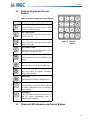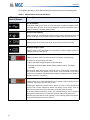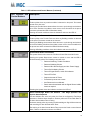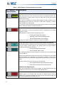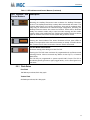
1
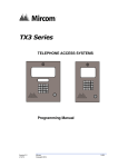
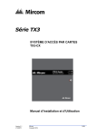
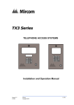
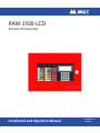
RAM-3500-LCD
Remote Annunciator
Installation and Operation Manual
LT-1093 Rev. 1
July 2014
Table of Contents
1.0
Introduction
6
1.1
Contact Us ..................................................................................................................... 6
2.0
Mechanical Installation
2.1
Mounting Dimensions .................................................................................................... 8
3.0
Configuring the Main Board
3.1
RAM-3500-LCD Main Board Components ..................................................................... 11
3.2
Dip Switches .................................................................................................................. 12
3.2.1
Setting the RAM-3500-LCD Address ............................................................................. 12
4.0
Wiring
4.1
RAM-3500-LCD Wiring .................................................................................................. 15
5.0
Operation
5.1
LCD Display ................................................................................................................... 16
5.2
Numeric Keypad and Cursor Buttons ............................................................................ 17
5.3
Common LED Indicators and Control Buttons ............................................................... 17
5.3.1
Flash Rates .................................................................................................................... 21
6.0
Specifications
6.1
Electrical Specifications ................................................................................................. 22
6.2
Current Drain for Battery Calculations ........................................................................... 22
6.3
Environmental Specifications ......................................................................................... 22
7.0
Warranty & Warning Information
8
11
14
16
22
23
3
List of Figures
4
Figure 1
Mounting the BB-1001 backbox directly to the wall ....................................................... 9
Figure 2
Installing the Annunciator Cover Bracket onto the RAM-3500-LCD .............................. 10
Figure 3
RAM-3500-LCD Remote Annunciator Main Board Layout ............................................. 11
Figure 4
Power Supply and RS-485 Wiring on the Main Board ................................................... 15
Figure 5
Numeric Keypad ............................................................................................................. 17
List of Tables
Table 1
Table 2
Table 3
Table 4
Table 5
Table 6
Table 7
Table 8
Table 9
Table 10
Table 11
BB-1001 Backbox Dimensions ......................................................................................
BB-1002 Backbox Dimensions ......................................................................................
BB-1003 Backbox Dimensions ......................................................................................
BB-1008 Backbox Dimensions ......................................................................................
BB-1012 Backbox Dimensions ......................................................................................
RAM-3500-LCD Remote Annunciator Main Board Component Functions ....................
RAM-3500-LCD Address Setting ...................................................................................
Configuring Functions ....................................................................................................
Wiring Table for Indicating and Auxiliary Power Circuits ...............................................
Numeric Keypad and Cursor Buttons ............................................................................
LED Indicators and Control Buttons ...............................................................................
8
8
8
8
8
11
12
13
14
17
18
5
Introduction
1.0
Introduction
The RAM-3500-LCD Remote Annunciator is used as a component of an FX-3500/MR-2350
Fire Alarm System. It provides an exact mimic of the FX-3500/MR-2350 display at a remote
location.
The RAM-3500-LCD features the following:
i
•
4 line LCD display.
•
Common feature LEDs and push buttons.
•
Alpha numeric keypad for the LCD.
Note:
Configuring FX-3500/MR-2350 Series fire alarm panels from this remote
annunciator is not permitted.
Each RAM-3500-LCD has its own address. Addresses available are 1 to 7 inclusive.
This annunciator may be selected to operate as an ancillary device by using the system
configurator and using DIP Switch SW1 to disable all buttons except:
i
•
Lamp Test.
•
Buzzer Silence.
•
Info and Arrow Buttons.
Note:
The ancillary device option takes priority over any other selections made on DIP
Switch.
For more information on how to configure the RAM-3500-LCD as an ancillary device, see
Describes the Jumpers, Ports, Switches and Potentiometer on the Main Board. on page 11.
1.1
Contact Us
For General Inquiries, Customer Service and Technical Support you can contact us Monday to
Friday 8:00 A.M. to 5:00 P.M. E.S.T.
6
Introduction
General Inquiries
Toll Free
1-888-660-4655 (North America Only)
Local
905-660-4655
Email
[email protected]
Customer Service
Toll Free
1-888-MIRCOM5 (North America Only)
Local
905-695-3535
Toll Free Fax
1-888-660-4113 (North America Only)
Local Fax
905-660-4113
Email
[email protected]
Technical Support
Toll Free
1-888-MIRCOM5 (North America Only)
Local
905-695-3535
Email
[email protected]
Website
www.mircom.com
7
Introduction
2.0
Mechanical Installation
The RAM-3500-LCD can be surface mounted using one of the BB-1000 series semi-flush
enclosures. The following table gives the backboxes, their dimensions, and their capacity.
Backbox Model
Dimensions
Chassis Capacity
BB-1001
9.00”H x 12.75”W x 1.20”D
1
BB-1002
18.00”H x 12.75”W x 1.20”D
2
BB-1003
26.4”H x 12.75”W x 1.2”D
3
BB-1008
33”H x 22.5”W x 1.25”D
8
BB-1012
45”H x 22.5”W x 1.25”D
12
These enclosures may also be mounted to a 4” square electrical box.
2.1
Mounting Dimensions
Table 1 BB-1001 Backbox Dimensions
Backbox Dimensions
9.00”H x 12.75”W x 1.20”D
Horizontal distance between mounting screws
9.95”
Vertical distance between mounting screws
7.50”
Table 2 BB-1002 Backbox Dimensions
Backbox Dimensions
18.00”H x 12.75”W x 1.20”D
Horizontal distance between mounting screws
9.95”
Vertical distance between mounting screws
16.5”
Table 3 BB-1003 Backbox Dimensions
Backbox Dimensions
26.4”H x 12.75”W x 1.20”D
Horizontal distance between mounting screws
9.95”
Vertical distance between mounting screws
24.90”
Table 4 BB-1008 Backbox Dimensions
Backbox Dimensions
33”H x 22.5”W x 1.25”D
Horizontal distance between mounting screws
20.9”
Vertical distance between mounting screws
35.2”
Table 5 BB-1012 Backbox Dimensions
8
Backbox Dimensions
45”H x 22.5”W x 1.25”D
Horizontal distance between mounting screws
20.9”
Vertical distance between mounting screws
52.0”
Introduction
How to mount the BB-1000 Series enclosures directly to the wall
1. Open the front door.
2. Mount the backbox to the wall using the four screws provided.
BACKBOX
WALL
DOOR
BACKBOX CAN BE MOUNTED
WITH STANDARD 4" X 4"
ELECTRICAL BOXES
12.75"
B
H
A
1.2"
BB-1001 BACKBOX IS SHOWN
#6-32
HEXNUTS
ANNUNCIATOR CHASSIS
Figure 1
Mounting the BB-1001 backbox directly to the wall
9
Introduction
How to mount the Annunciator Cover Bracket onto the RAM-3500-LCD
1. Place the RAM-3500-LCD into the backbox, ensure that the mounting holes on the
annunciator line up with the studs in the backbox.
2. Place the Annunciator Cover Bracket over the RAM-3500-LCD and use the nuts
provided with the backbox to secure the assembly. Refer to the figure below.
Figure 2
10
Installing the Annunciator Cover Bracket onto the RAM-3500-LCD
Introduction
3.0
Configuring the Main Board
SW2
ADDRESS
SW1
CONFIG
Figure 3
3.1
P2 DISPLAY EXPANSION OUT
+ IN - + OUT - + IN -
24 VDC
S
RS-485
+ OUT - S
JW1
EOL
RAM-3500-LCD Remote Annunciator Main Board Layout
RAM-3500-LCD Main Board Components
Describes the Jumpers, Ports, Switches and Potentiometer on the Main Board.
Table 6 RAM-3500-LCD Remote Annunciator Main Board Component Functions
Component
Function
JW1
EOL. If annunciator is last in line move jumper to right most pins.
P2
Connect to RAX-1048TZDS with a ribbon cable.
SW1
Configures specific functions. For more information see Table 8
Configuring Functions on page 13.
SW2
Configures address of RAM-3500-LCD. For more information see SW2
configures the address of the RAM-3500-LCD. Address 1 to 7 inclusive are
valid for all RAM-3500-LCD Annunciators in the system. Table 7 RAM3500-LCD Address Setting describes the switch settings for each
address. on page 12
11
Introduction
3.2
Dip Switches
The RAM-3500-LCD utilizes two DIP switches for configuring the address and available
functions.
3.2.1 Setting the RAM-3500-LCD Address
SW2 configures the address of the RAM-3500-LCD. Address 1 to 7 inclusive are valid for all
RAM-3500-LCD Annunciators in the system. Table 7 RAM-3500-LCD Address Setting
describes the switch settings for each address.
Table 7 RAM-3500-LCD Address Setting
Address
DIP Switch Setting
0
1
5
0
0
6
0
0
12
1
2
3
4
ON
1
1
1
0
0
4
1
7
0
0
1
1
2
3
4
1
2
3
4
ON
0
1
2
3
4
ON
3
1
0
1
1
1
1
2
3
4
ON
0
1
2
3
4
ON
2
0
0
0
1
DIP Switch Setting
ON
1
0
1
2
3
4
ON
1
Address
Introduction
3.2.2 Configuring Functions
SW1 configures the functions of the RAM-3500-LCD. Table 8 Configuring Functions describes
the switch settings for each function.
Table 8 Configuring Functions
Function
1
2
3
4
5
6
7
8
1
2
3
4
5
6
7
8
ON
1
2
3
4
5
6
7
8
ON
1
2
3
4
5
6
7
8
ON
1
2
3
4
5
6
7
8
ON
1
2
3
4
5
6
7
8
Disable
Set switch to ON
ON
5
1
2
3
4
5
6
7
8
ON
Buzzer Silence
4
1
2
3
4
5
6
7
8
ON
Lamp Test Button
3
1
2
3
4
5
6
7
8
ON
Fire Drill Button
2
1
2
3
4
5
6
7
8
ON
Signal Silence Button
1
Enable
Set switch to OFF
ON
System Reset Button
Switch #
13
Introduction
4.0
Wiring
The RS-485 Wiring to the RAM-3500-LCD is recommended to be Twisted Shielded Pair. The
wire must follow:
•
300mA power limited
•
22 AWG maximum of 2000 feet
•
20 AWG maximum of 4000 feet
•
18 AWG maximum of 8000 feet
•
Maximum 40 ohm loop resistance
The 24VDC field wiring needs to be of an appropriate gauge for the number of annunciators
and the total wiring run length.
See 6.2 Current Drain for Battery Calculations on page 22 to calculate the Maximum current
for all annunciators summed together.
For information on wiring the RAX-1048TZDS Annunciator Adder Modules to the Main
Board see RAX-1048TZDS.
i
Note:
!
All circuits are power limited and must use type FPL, FPLR or FPLP Power
Limited Cable.
Attention: Accidentally connecting any of the 24V DC wires to the RS-485 wiring
will result in damage to the Annunciator and/or to the Fire Alarm
Control Panel to which it is connected.
Table 9 Wiring Table for Indicating and Auxiliary Power Circuits
Total
Maximum
Current for all
Annunciators
14
Maximum Wiring Run to Last Annunciator
18AWG
16AWG
14AWG
12AWG
Max.
Loop
Resistance
Amperes
ft
m
ft
m
ft
m
ft
m
Ohms
0.06
2350
716
3750
1143
6000
1829
8500
2591
30
0.12
1180
360
1850
567
3000
915
4250
1296
15
0.30
470
143
750
229
1200
366
1900
579
6
0.60
235
71
375
114
600
183
850
259
3
0.90
156
47
250
76
400
122
570
174
2
1.20
118
36
185
56
300
91
425
129
1.5
1.50
94
29
150
46
240
73
343
105
1.2
1.70
78
24
125
38
200
61
285
87
1.0
Introduction
4.1
RAM-3500-LCD Wiring
+
+
+
S
+
S
-
Figure 4
i
Note:
Power Supply and RS-485 Wiring on the Main Board
RS-485 connection is supervised locally by both the FACP and annunciator. All
circuits are power limited and supervised.
15
Introduction
5.0
Operation
5.1
LCD Display
The display is a four line, 20 character back-lit alphanumeric LCD. It displays information
regarding the panel, its circuits, and devices. An on-screen cursor is controlled by the cursor
buttons for menu selection and control. Report information provided by the LCD display
includes:
•
Alarm Log
•
Event Log
•
Current Levels
•
Device Information
•
Verification and Maintenance Reports
Use the cursor buttons on the Numeric Keypad for menu selection and control. For more
information see 5.2 Numeric Keypad and Cursor Buttons.
16
Introduction
5.2
Numeric Keypad and Cursor
Buttons
Table 10 Numeric Keypad and Cursor Buttons
Key
2
ABC
4
GHI
6
MNO
8
TUV
X
M
?
1
2
ABC
3
X
6
M
9
?
DEF
Description
Key 2 (Up cursor)
Press this button to move the cursor or scroll
up lists in a continuous loop.
Key 4 (Left Cursor)
Press this button to move the cursor or select
options to the left.
4
5
GHI
JKL
7
8
PRS
TUV
*
0
QZ
MNO
WXY
#
Key 6 (Right Cursor)
Press this button to move the cursor or select
options to the right.
Figure 5
Numeric
Keypad
Key 8 (Down Cursor)
Press this button to move the cursor or scroll
down lists in a continuous loop.
Cancel Button
Press this button to cancel an operation or exit
a menu.
Menu Button
Press this button to view the command menu.
Info Button
Press this button for detailed information
about a displayed item.
Enter Button
Press this button to select a displayed item.
Star Button
*
#
5.3
Press this button to move the cursor to the left
for certain configurations such as entering a
device address.
Hash Button
Press this button to move the cursor to the
right for certain configurations such as
entering a device address.
Common LED Indicators and Control Buttons
17
Introduction
For complete descriptions of all LED indicators and control buttons see the following table.
Table 11 LED Indicators and Control Buttons
LED Indicator and
Control Buttons
Description
AC On Indicator
Illuminates steady green when the main AC power is within acceptable levels.
The LED turns off when the level falls below the power-fail threshold and the
panel is switched to standby (battery) power.
Ground Fault Indicator
Flashes yellow at the Trouble rate when a Ground Fault is detected on any field
wiring. Clearing the Ground Fault clears the indication and turns the LED off.
CPU Fault Indicator
Flashes yellow at the Trouble rate when the processor ceases functioning.
Battery/Charger Trouble
Flashes yellow at the Slow Flash rate. Clearing the trouble condition clears the
indication and turns the LED off.
Alarm Queue Button and Indicator
Flashes red when there is an alarm in queue. The buzzer sounds steady.
An alarm can be generated in two ways
• When any Alarm configured point or input activates.
• Pressing the General Alarm button and the system is set for Two Stage
operation.
Pressing the Alarm Queue button allows the user to cycle through and review a
list of active alarms from oldest to most recent. Once all alarms in the queue
have been reviewed the LED will illuminate steady. Resetting the panel clears the
indication and turns the LED off.
Supervisory Queue Button and Indicator
Flashes yellow at the Fast Flash Rate when a Latching or Non-Latching circuit is
activated. The buzzer sounds at the fast rate.
Pressing the Supervisory Queue button allows the user to cycle through and
review a list of active supervisory alarms from oldest to most recent. Once all
alarms in the queue have been reviewed the LED will illuminate steady.
If all Non-Latching Supervisory circuits are restored and there are no Latching
Supervisory Circuits active, the indication will clear and the LED will turn off.
Resetting the panel will clear the activation of any Latching Supervisory Alarms,
clears the indication and turns the LED off.
18
Introduction
Table 11 LED Indicators and Control Buttons (Continued)
LED Indicator and
Control Buttons
Description
Trouble Queue Button and Indicator
Flashes yellow when any trouble condition is detected on the panel. The buzzer
sounds at the slow rate.
Pressing the Trouble Queue button allows the user to cycle through and review a
list of active Troubles from oldest to most recent. Once all troubles in the queue
have been reviewed the LED will illuminate steady.
Clearing all Trouble conditions clears the indication and turns the LED off.
Building Queue Button and Indicator
Flashes yellow at the Trouble Flash rate when any Building condition is detected
on the panel. The buzzer sounds at the fast rate.
Pressing the Building Queue button allows the user to cycle through and review a
list of active Building Conditions from oldest to most recent. Once all conditions in
the queue have been reviewed the LED will illuminate steady.
Clearing all Building conditions clears the indication and turns the LED off.
System Reset Button and Indicator
The System Reset button resets the Fire Alarm Control Panel and all Circuits.
Pressing the System Reset button causes a trouble to occur and the LED to
illuminate steady yellow. The following events will occur
•
Resets all Latching, Trouble Conditions.
•
Resets all Initiating Circuits.
•
Resets 4-Wire Smoke Supply and Aux. Power Supply.
•
Turns off all Indicating Circuits.
•
Turns off Signal Silence, Ack & GA Indicators.
•
Turns off Fire Drill.
•
Stops and resets all Timers.
•
Processes inputs as new events.
•
Aux Disconnect is not affected.
•
Reset cannot be activated until the Signal Silence Inhibit
timer has expired.
Resetting the System clears the indication and turns the LED off.
Alarm Acknowledge Button and Indicator - Two Stage Operation and
Positive Alarm Sequence
LED and Indicator are active only when the Panel is configured for Two Stage
Operation or Positive Alarm Sequence. Flashes yellow at the Fast Flash Rate as
the Auto General Alarm Timer is timing.
Illuminates steady yellow by pressing the Acknowledge or Signal Silence buttons
and cancelling the Auto General Alarm Timer.
The expiring of the Auto General Alarm Timer causes the Panel to enter General
Alarm, clears the indication and turns the LED off.
19
Introduction
Table 11 LED Indicators and Control Buttons (Continued)
LED Indicator and
Control Buttons
Description
Automatic Alarm Signal Cancel Button and Indicator
Automatic Alarm
Signal Cancel
LED and Indicator are active only when the Panel is configured for PAS or Two
Stage Operation. Flashes yellow at the Fast Flash Rate as the Auto General
Alarm Timer is timing.
If the panel is configured for Positive Alarm Sequence (PAS), activation of the
Acknowledge button within 15 seconds of a PAS alarm will delay a common
alarm activation for 180 seconds.
The expiring of the Auto General Alarm Timer causes the Panel to enter General
Alarm, clears the indication and turns the LED off.
General Alarm Button and Indicator - Two Stage Operation or PAS
LED and Indicator are active only when the Panel is configured for Two Stage
Operation or PAS.
LED illuminates steady red when the following occurs:
•
Pressing the General Alarm button.
•
Activating a General Alarm Initiating Circuit.
•
The Auto General Alarm Timer expiring.
Resetting the System clears the indication and turns the LED off.
Signal Silence/Releasing Service Signal Silence Button and Indicator
Use Releasing Service Signal Silence for releasing operation and Signal Silence
for other modes. Flashes yellow at the Trouble Flash rate when Indication
Circuits are silenced by the following:
•
Pressing the Signal SIlence button.
•
The Auto Signal SIlence Timer.
Any Subsequent Alarms cause the Signals to resound, clears the indication and
turns the LED off.
Pressing the Signal Silence button when the Panel is in Alarm turns on the Signal
Silence Indicator and deactivates any Silenceable Indicating Circuits. NonSilenceable Circuits are unaffected. Signals will re-sound upon any subsequent
Alarm.
This button does not function during one of the following:
•
Any configured Signal Silence Inhibit Timer period.
•
If Fire Drill has activated the Indicating Circuits.
Additional Two Stage Function
If the Auto General Alarm Timer has not expired, this Signal Silence button also
performs the same function as the Alarm Acknowledge button.
Buzzer Silence Button and Indicator
Flashes yellow at the Trouble Flash rate when the Buzzer Silence button is
pressed. Any new alarm, supervisory or trouble events resounds the buzzer and
will cause the Buzzer Silence LED to turn off.
20
Introduction
Table 11 LED Indicators and Control Buttons (Continued)
LED Indicator and
Control Buttons
Description
Auxiliary Disconnect Button and Indicator
Activating the Auxiliary Disconnect button activates the Auxiliary Disconnect
function. The Auxiliary Alarm Relay is always disconnected with this button. The
Common Alarm Relay, the Common Supervisory relay and all correlated alarm
relays may be disconnected as selected through configuration. Activating the
Auxiliary Disconnect button also causes the Common Trouble LED to illuminate
steady, the common trouble relay to send a trouble message and the trouble
buzzer to flash at the trouble flash rate. Pressing the Auxiliary Disconnect button
again de-activates this function and the system will go back to normal.
Visual Indicator Test Button and Indicator
Visual
Indicator Test
Pressing the Visual Indicator Test button illuminates all front panel LEDs on
steady in the appropriate color and turns the buzzer on steady. If Visual Indicator
Test is active for more than 10 seconds, Common Trouble is activated.
Fire Drill Button and Indicator
Illuminates steady yellow during an active Fire Drill.
Pressing the Fire Drill button activates all programmed and non-Disconnected
Indicating Circuits. It does not transmit any Alarms via the City Tie, or Common
Alarm Relay.
Fire Drill may be programmed to operate specific NAC Circuits. Fire Drill is
cancelled by pressing the button again (toggle switch), or if the Panel goes into a
real Alarm.
5.3.1 Flash Rates
Fast Flash
120 flashes per minute, 50% duty cycle.
Trouble Flash
20 flashes per minute, 50% duty cycle.
21
Introduction
6.0
Specifications
6.1
Electrical Specifications
24 VDC power limited nominal voltage
Standby 70mA Max., Alarm 100mA Max. All LEDs illuminated 40 mA Max.
6.2
Current Drain for Battery Calculations
The maximum normal current drain will be during Lamp Test when all lamps are illuminated on
one chassis at a time. Thus the currents are:
•
Normal Standby = 70mA
•
Maximum = 100mA
The Normal Standby Current is used for battery size calculations (see the FX-3500/MR-2350
Fire Alarm Control Panel manual for battery calculations) and includes the current drain for the
Trouble Buzzer, Trouble LED, and one Alarm LED. The Maximum Current is used to calculate
the wire size (see ‘section above).
6.3
Environmental Specifications
This annunciator is intended for indoor use only.
22
Introduction
7.0
Warranty & Warning Information
Warning Please Read Carefully
Note to End Users: This equipment is subject to terms and conditions of sale as follows:
Note to Installers
This warning contains vital information. As the only individual in contact with system users, it is
your responsibility to bring each item in this warning to the attention of the users of this
system. Failure to properly inform system end-users of the circumstances in which the system
might fail may result in over-reliance upon the system. As a result, it is imperative that you
properly inform each customer for whom you install the system of the possible forms of failure.
System Failures
This system has been carefully designed to be as effective as possible. There are
circumstances, such as fire or other types of emergencies where it may not provide protection.
Alarm systems of any type may be compromised deliberately or may fail to operate as
expected for a variety of reasons. Some reasons for system failure include:
•Inadequate Installation
A Fire Alarm system must be installed in accordance with all the applicable codes and
standards in order to provide adequate protection. An inspection and approval of the initial
installation, or, after any changes to the system, must be conducted by the Local Authority
Having Jurisdiction. Such inspections ensure installation has been carried out properly.
•Power Failure
Control units, smoke detectors and many other connected devices require an adequate power
supply for proper operation. If the system or any device connected to the system operates
from batteries, it is possible for the batteries to fail. Even if the batteries have not failed, they
must be fully charged, in good condition and installed correctly. If a device operates only by
AC power, any interruption, however brief, will render that device inoperative while it does not
have power. Power interruptions of any length are often accompanied by voltage fluctuations
which may damage electronic equipment such as a fire alarm system. After a power
interruption has occurred, immediately conduct a complete system test to ensure that the
system operates as intended.
•Failure of Replaceable Batteries
Systems with wireless transmitters have been designed to provide several years of battery life
under normal conditions. The expected battery life is a function of the device environment,
usage and type. Ambient conditions such as high humidity, high or low temperatures, or large
temperature fluctuations may reduce the expected battery life. While each transmitting device
has a low battery monitor which identifies when the batteries need to be replaced, this monitor
may fail to operate as expected. Regular testing and maintenance will keep the system in
good operating condition.
•Compromise of Radio Frequency (Wireless) Devices
Signals may not reach the receiver under all circumstances which could include metal objects
placed on or near the radio path or deliberate jamming or other inadvertent radio signal
interference.
•System Users
A user may not be able to operate a panic or emergency switch possibly due to permanent or
temporary physical disability, inability to reach the device in time, or unfamiliarity with the
correct operation. It is important that all system users be trained in the correct operation of the
alarm system and that they know how to respond when the system indicates an alarm.
•Automatic Alarm Initiating Devices
Smoke detectors, heat detectors and other alarm initiating devices that are a part of this
system may not properly detect a fire condition or signal the control panel to alert occupants of
a fire condition for a number of reasons, such as: the smoke detectors or heat detector may
have been improperly installed or positioned; smoke or heat may not be able to reach the
23
Introduction
alarm initiating device, such as when the fire is in a chimney, walls or roofs, or on the other
side of closed doors; and, smoke and heat detectors may not detect smoke or heat from fires
on another level of the residence or building.
•Software
Most MGC products contain software. With respect to those products, MGC does not warranty
that the operation of the software will be uninterrupted or error-free or that the software will
meet any other standard of performance, or that the functions or performance of the software
will meet the user’s requirements. MGC shall not be liable for any delays, breakdowns,
interruptions, loss, destruction, alteration or other problems in the use of a product arising our
of, or caused by, the software.
Every fire is different in the amount and rate at which smoke and heat are generated. Smoke
detectors cannot sense all types of fires equally well. Smoke detectors may not provide timely
warning of fires caused by carelessness or safety hazards such as smoking in bed, violent
explosions, escaping gas, improper storage of flammable materials, overloaded electrical
circuits, children playing with matches or arson.
Even if the smoke detector or heat detector operates as intended, there may be circumstances
when there is insufficient warning to allow all occupants to escape in time to avoid injury or
death.
•Alarm Notification Appliances
Alarm Notification Appliances such as sirens, bells, horns, or strobes may not warn people or
waken someone sleeping if there is an intervening wall or door. If notification appliances are
located on a different level of the residence or premise, then it is less likely that the occupants
will be alerted or awakened. Audible notification appliances may be interfered with by other
noise sources such as stereos, radios, televisions, air conditioners or other appliances, or
passing traffic. Audible notification appliances, however loud, may not be heard by a hearingimpaired person.
•Telephone Lines
If telephone lines are used to transmit alarms, they may be out of service or busy for certain
periods of time. Also the telephone lines may be compromised by such things as criminal
tampering, local construction, storms or earthquakes.
•Insufficient Time
There may be circumstances when the system will operate as intended, yet the occupants will
not be protected from the emergency due to their inability to respond to the warnings in a
timely manner. If the system is monitored, the response may not occur in time enough to
protect the occupants or their belongings.
•Component Failure
Although every effort has been made to make this system as reliable as possible, the system
may fail to function as intended due to the failure of a component.
•Inadequate Testing
Most problems that would prevent an alarm system from operating as intended can be
discovered by regular testing and maintenance. The complete system should be tested as
required by national standards and the Local Authority Having Jurisdiction and immediately
after a fire, storm, earthquake, accident, or any kind of construction activity inside or outside
the premises. The testing should include all sensing devices, keypads, consoles, alarm
indicating devices and any other operational devices that are part of the system.
•Security and Insurance
Regardless of its capabilities, an alarm system is not a substitute for property or life insurance.
An alarm system also is not a substitute for property owners, renters, or other occupants to act
prudently to prevent or minimize the harmful effects of an emergency situation.
24
Introduction
IMPORTANT NOTE: End-users of the system must take care to ensure that the system,
batteries, telephone lines, etc. are tested and examined on a regular basis to ensure the
minimization of system failure.
Limited Warranty
Mircom Technologies Ltd., MGC Systems Corp. and MGC System International Ltd. together
with their subsidiaries and affiliates (collectively, MGC) warrants the original purchaser that for
a period of three years from the date of shipment, proprietary manufactured product shall be
free of defects in materials and workmanship, under normal use. During the warranty period,
MGC shall, at its option, repair or replace any defective product upon return of the product to
its factory, at no charge for labor and materials. Non-proprietary, third party or OEM product
shall be warranted in accordance with the warranty period of the manufacturer. Any
replacement and/or repaired parts are warranted for the remainder of the original warranty or
ninety (90) days, whichever is longer. The original owner must promptly notify MGC in writing
that there is defect in material or workmanship, such written notice to be received in all events
prior to expiration of the warranty period.
International Warranty
The warranty for international customers is the same as for any customer within Canada and
the United States, MGC shall not be responsible for any customs fees, taxes, or VAT that may
be due.
Conditions to Void Warranty
This warranty applies only to defects in parts and workmanship relating to normal use. It does
not cover:
•damage incurred in shipping or handling;
•damage caused by disaster such as fire, flood, wind, earthquake or lightning;
•damage due to causes beyond the control of MGC such as excessive voltage, mechanical
shock or
•water damage;
•damage caused by unauthorized attachment, alterations, modifications or foreign objects;
•damage caused by peripherals (unless such peripherals were supplied by MGC);
•defects caused by failure to provide a suitable installation environment for the products;
•damage caused by use of the products for purposes other than those for which it was
designed;
•damage from improper maintenance;
•damage arising out of any other abuse, mishandling or improper application of the products.
Warranty Procedure
To obtain service under this warranty, please return the item(s) in question to the point of
purchase. All authorized distributors and dealers have a warranty program. Anyone returning
goods to MGC must first obtain an authorization number. MGC will not accept any shipment
whatsoever for which prior authorization has not been obtained. NOTE: Unless specific preauthorization in writing is obtained from MGC management, no credits will be issued for
custom fabricated products or parts or for complete fire alarm system. MGC will at its sole
option, repair or replace parts under warranty. Advance replacements for such items must be
purchased.
25
Introduction
Note: MGC’s liability for failure to repair the product under this warranty after a reasonable
number of attempts will be limited to a replacement of the product, as the exclusive remedy for
breach of warranty.
Disclaimer of Warranties
This warranty contains the entire warranty and shall be in lieu of any and all other warranties,
whether expressed or implied (including all implied warranties of merchantability or fitness for
a particular purpose) and of all other obligations or liabilities. MGC neither assumes nor
authorizes any other person purporting to act on its behalf to modify or to change this
warranty, or to assume for it any other warranty or liability concerning this product.
This disclaimer of warranties and limited warranty are governed by the laws of the province of
Ontario, Canada.
Out of Warranty Repairs
MGC will at its option repair or replace out-of-warranty products which are returned to its
factory according to the following conditions. Anyone returning goods to MGC must first obtain
an authorization number. MGC will not accept any shipment whatsoever for which prior
authorization has not been obtained.
Products which MGC determines to be repairable will be repaired and returned. A set fee
which MGC has predetermined and which may be revised from time to time, will be charged
for each unit repaired.
Products which MGC determines not to be repairable will be replaced by the nearest
equivalent product available at that time. The current market price of the replacement product
will be charged for each replacement unit.
The foregoing information is accurate as of the date of publishing and is subject to change or
revision without prior notice at the sole discretion of the Company
WARNING: Mircom recommends that the entire system be completely tested on a regular basis.
However, despite frequent testing, and due to, but not limited to, criminal tampering or electrical
disruption, it is possible for this product to fail to perform as expected.
NOTE: Under no circumstances shall Mircom be liable for any special, incidental, or consequential
damages based upon breach of warranty, breach of contract, negligence, strict liability, or any
other legal theory. Such damages include, but are not limited to, loss of profits, loss of the product
or any associated equipment, cost of capital, cost of substitute or replacement equipment,
facilities or services, down time, purchaser’s time, the claims of third parties, including
customers, and injury to property.
MIRCOM MAKES NO WARRANTY OF MERCHANTABILITY OR FITNESS FOR A PARTICULAR
PURPOSE WITH RESPECT TO ITS GOODS DELIVERED, NOR IS THERE ANY OTHER WARRANTY,
EXPRESSED OR IMPLIED, EXCEPT FOR THE WARRANTY CONTAINED HEREIN.
26
CANADA - Main Office
25 Interchange Way
Vaughan, ON L4K 5W3
Tel: (888) 660-4655
(905) 660-4655
Fax: (905) 660-4113
U.S.A
4575 Witmer Industrial Estates
Niagara Falls, NY 14305
Tel: (888) 660-4655
(905) 660-4655
Fax: (905) 660-4113
TECHNICAL SUPPORT
North America
Tel: (888) Mircom5
(888) 647-2665
International
Tel: (905) 647-2665
© MGC 2014
Printed in Canada
Subject to change without prior notice
www.mircomgroup.com