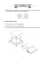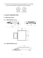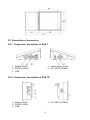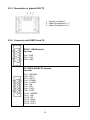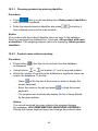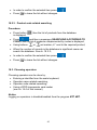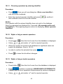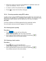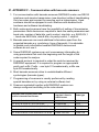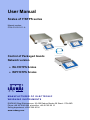
1
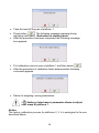
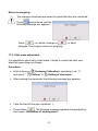
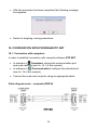
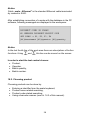
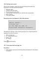
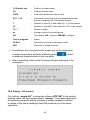
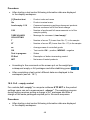
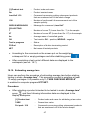
User Manual
Scales of Y/KTPS series
Manual number:
ITKU-51-03-01-11-A
Control of Packaged Goods
Network version
• WLY/KTPS Scales
• WPY/KTPS Scales
MANUFACTURER OF ELECTRONIC
WEIGHING INSTRUMENTS
RADWAG Wagi Elektroniczne, 26–600 Radom Bracka 28 Street - POLAND
Phone +48 48 38 48 800, phone/fax. +48 48 385 00 10
Selling department +48 48 366 80 06
www.radwag.com
JANUARY 2011
2
Table OF CONTENTS
1.
2.
3.
4.
INTENDED USE..........................................................................................................................5
PRECAUTIONARY MEASURES................................................................................................5
WARRANTY CONDITIONS........................................................................................................6
UNPACKING AND MOUNTING .................................................................................................6
4.1. WPY/KTPS/C1 scales ...........................................................................................................6
4.2. WPY/KTPS/D2 scales ...........................................................................................................7
5. SCALE CONSTRUCTION ..........................................................................................................8
5.1. Main dimensions....................................................................................................................8
5.1.1. WPY/KTPS/C1 scales ................................................................................................8
5.1.2. WPY/KTPS/D2 scales ................................................................................................8
5.2. Description of connectors ......................................................................................................9
5.2.1. Connectors’ description in PUE 7 ...............................................................................9
5.2.2. Connectors’ description in PUE 7P.............................................................................9
5.2.3. Description of glands PUE 7P ..................................................................................10
5.2.4. Connector with RS232 and I/O .................................................................................10
6. GETTING STARTED ................................................................................................................11
7. KEYPAD OVERLAY .................................................................................................................11
8. FUNCTIONS OF KEYS.............................................................................................................12
8.1. Keys on the overlay .............................................................................................................12
8.2. Screen function buttons.......................................................................................................12
9. INDICATING WINDOW.............................................................................................................13
10. PROGRAM STRUCTURE ......................................................................................................14
10.1. Inventory of parameters ....................................................................................................15
10.1.1. Scale parameters - weighing..................................................................................15
10.1.2. Communication ......................................................................................................15
10.1.3. Devices ..................................................................................................................16
10.1.4. Display ...................................................................................................................17
10.1.5. Others ....................................................................................................................17
10.1.6. User Calibration .....................................................................................................18
10.2. Navigating within the menu ...............................................................................................18
10.2.1. Buttons ...................................................................................................................18
10.2.2. Return to weighing .................................................................................................19
11. WEIGHING ..............................................................................................................................20
11.1. Conditions of operational use ...........................................................................................20
11.2. Zeroing ..............................................................................................................................21
11.3. Tarring...............................................................................................................................21
11.4. Weighing for dual range scales.........................................................................................22
12. SCALE PARAMETERS ..........................................................................................................22
12.1. Median filter.......................................................................................................................23
12.2. Filter ..................................................................................................................................23
12.3. Autozero ............................................................................................................................24
12.4. Minimum weight for different functions (LO) .....................................................................24
13. COMMUNICATION .................................................................................................................25
13.1. RS 232 settings .................................................................................................................25
13.2. ETHERNET setting ...........................................................................................................25
13.3. TCP protocol setting .........................................................................................................26
14. DEVICES.................................................................................................................................26
14.1. Computer ..........................................................................................................................26
14.1.1. Computer port ........................................................................................................27
3
14.1.2. Computer address..................................................................................................27
14.2. Printer................................................................................................................................27
14.2.1. Printer port .............................................................................................................28
14.2.2. Printer code page ...................................................................................................28
14.3. Barcode scanner ...............................................................................................................28
14.3.1. Port for barcode scanner........................................................................................29
14.3.2. Offset......................................................................................................................29
14.3.3. Code length ............................................................................................................29
14.4. Transponder card reader ..................................................................................................30
14.4.1. Com port for transponder card readers..................................................................30
15. DISPLAY .................................................................................................................................31
15.1. Function keys ....................................................................................................................31
15.2. Displaying platforms..........................................................................................................32
16. OTHER PARAMETERS..........................................................................................................33
16.1. Languages ........................................................................................................................33
16.2. Setting date and time ........................................................................................................33
16.3. Sound signal .....................................................................................................................34
16.4. Touch panel calibration .....................................................................................................34
16.5. Software version ...............................................................................................................35
16.6. Factory number .................................................................................................................35
17. CUSTOMER CALIBRATION ..................................................................................................35
17.1. Calibration procedure........................................................................................................35
17.2. Start mass adjustment ......................................................................................................37
18. COOPERATION WITH PROGRAM KTP NET .......................................................................38
18.1. Connection with computers...............................................................................................38
18.2. Choosing product ..............................................................................................................39
18.2.1. Choosing products by entering identifier................................................................40
18.2.2. Product name related searching ............................................................................40
18.2.3. Product code related searching .............................................................................41
18.3. Choosing operators...........................................................................................................41
18.3.1. Choosing operators by entering identifier ..............................................................42
18.3.2. Wybór z listy po nazwie operatora .........................................................................42
18.3.3. Wybór z listy po kodzie operatora ..........................................................................42
18.3.4. Choosing operators using RFID readers................................................................43
18.4. Entering batch quantity .....................................................................................................43
18.5. Entering a batch number...................................................................................................43
18.6. Starting test control ...........................................................................................................44
18.7. Test control with average tare...........................................................................................44
18.8. Empty – full control ...........................................................................................................45
18.9. Full – empty control...........................................................................................................46
18.10. Estimating average tare..................................................................................................47
19. TECHNICAL PARAMETERS .................................................................................................49
19.1. Scales of WLY/KTPS series .............................................................................................49
19.2. Scales of WPY/KTPS series .............................................................................................50
20. ERROR MESSAGES ..............................................................................................................51
21. APPENDIX F - Communication with barcode scanners ....................................................52
4
1. INTENDED USE
Scales of WPY/KTPS series together with KTP NET software constitute
a multi-stand system (network). Each scale is an independent scale and
information about the status of testing are sent in real time. The computer
program allows to collect data in real time from every connected scale.
The system allows to start test controls from scales or the computer level.
Cooperation scale-computer:
• Inventory of subsequent weighings in the database,
• Automatic printout of reports directly after a control has been completed,
• Sending identity codes from a scale to the computers to identify goods
and operators (product code, operator code, batch quantity, batch
number, Start/Stop test control),
• Defining product codes with descriptions (names) on the computer level.
Users can add individual names that are specific for the working place.
2. PRECAUTIONARY MEASURES
A. Please, read carefully this user manual before and use the device
according to its intended use;
B. Weighed loads should be placed in possibly central part of scale pan;
C. Do not clean the device with agents causing corrosion;
D. Weighing pan should be loaded with goods having gross mass lower
than maximal capacity of the scale;
E. Do not leave loads on the pan for longer period of time ;
F. In case of failure, immediately disconnect scale power supply;
G. Devices that are to be withdrawn from usage should be utilized
according to the law.
5
3. WARRANTY CONDITIONS
A. RADWAG is obliged to repair or change those elements that appears
to be faulty because of production and construction reason,
B. Defining defects of unclear origin and outlining methods of elimination
can be settled only in participation of a user and the manufacturer
representatives,
C. RADWAG does not take any responsibility connected with destructions
or losses derives from non-authorized or inappropriate (not adequate
to manuals) production or service procedures,
D. Warranty does not cover:
• Mechanical failures caused by inappropriate maintenance of
the device or failures of thermal or chemical origin or caused
by atmospheric discharge, overvoltage in mains or other
random event,
• Inappropriate cleaning.
E. Loss of warranty appears after:
• Access by an unauthorized service,
• Intrusion into mechanical or electronic construction
of unauthorized people,
• Installing another operating system,
• Removing or destroying protection stickers.
F. The detailed warranty conditions one can find in warranty certificate.
G. Contact with the central authorized service:
+48 48 384 88 00 ext. 106 or 107.
4. UNPACKING AND MOUNTING
4.1. WPY/KTPS/C1 scales
A. Take the device out of the package,
B. Put the scale on an even stiff ground,
C. Remove transport protection:
6
D. Scale should be levelled by turning regulation feet. Levelling is correct
if air bubble is situated in the central position:
4.2. WPY/KTPS/D2 scales
A. Take the device out of the package,
B. Put the scale on an even stiff ground,
C. Fit the pan and the bracket under the device according to the drawing:
7
E. Scale should be levelled by turning regulation feet. Levelling
is correct if air bubble is situated in the central position:
5. SCALE CONSTRUCTION
5.1. Main dimensions
5.1.1. WPY/KTPS/C1 scales
5.1.2. WPY/KTPS/D2 scales
8
5.2. Description of connectors
5.2.1. Connectors’ description in PUE 7
1 – Ethernet RJ45
2 – RS232 (COM1)
3 – USB
1 – power supply socket
2 – I/O, RS232 (COM2)
5.2.2. Connectors’ description in PUE 7P
1 – Ethernet RJ45
2 – RS232 (COM1)
3 – USB
1 – I/O, RS232 (COM2)
9
5.2.3. Description of glands PUE 7P
1 – Supply cord gland
2 – Gland for platforms 1, 2
3 – Gland for platforms 3, 4
5.2.4. Connector with RS232 and I/O
RS232 - DB9/M (male),
top view:
Pin2 - RxD
Pin3 - TxD
Pin5 - GND
I/O, RS232 DSUB15/F (female),
top view:
Pin1 - GNDWE
Pin2 - OUT1
Pin3 - OUT2
Pin4 - COMM
Pin5 - 6÷9VDC
Pin6 - IN4
Pin7 - IN3
Pin8 - TxD2
Pin9 - 5VDC
Pin10 - GNDRS
Pin11 - IN2
Pin12 - IN1
Pin13 - RxD2
Pin14 - OUT4
Pin15 - OUT3
10
6. GETTING STARTED
• After the terminal is connected to power the ON/LOAD
diode starts to light.
to start the operating system loading procedure.
• Press
Windows CE together with RADWAG software loading is signalled
by blinking the red diode ON/LOAD.
• When the loading procedure is completed the main software
window appears.
7. KEYPAD OVERLAY
11
8. FUNCTIONS OF KEYS
8.1. Keys on the overlay
Key
Description
Turning on/off the scale
Zeroing
Tarring
Confirmation of weighing
Entering the scale menu (not active after establishing
a connection with the computer)
Selecting products
Selecting operators
Batch quantity declaration
8.2. Screen function buttons
Key
Description
Batch number declaration
Starting / completing test controls
Open the list of operators
Open the list of products
Entering density
Starting the procedure of estimating the average tare
12
Moving left the description line for button functions.
Scrolling up the list of operators or products
Moving right the description line for button functions.
Scrolling down the list of operators or products
Leaving the screen displaying the list of operators or
products
9. INDICATING WINDOW
In the main application window one can see four separate parts:
1. The working mode information is displayed in the top part of the display.
It is accompanied by date and time. Additionally following functions are
accessible:
• operator „Logout”,
• show / hide the screen keyboard (button
)
2. Below the status bar you can see weighing window(s).:
3. There is a workspace below this window:
• In case of lack of communication with the computer the screen
looks like below:
13
• If a scale establishes connection with the database following
messages are displayed in the workspace:
Notice:
Description of setting codes and cooperation with PC software
KTP NET 2003 can be found in ch. 18 of this manual.
4. There are screen buttons below the workspace (description of button
functions – see ch. 8.2 of this manual)::
10. PROGRAM STRUCTURE
The main menu has been divided into six functional groups.
In every group there are parameters of similar use.
Icon
Description
Scale
Communication
Devices
Display
Other
User Calibration
14
10.1. Inventory of parameters
10.1.1. Scale parameters - weighing
Icon
Description
Value
Platform 1
-
Median Filter
0.5
Filter
Fast
Autozero
Yes
LO threshold
0
Weighing software version
2.0
10.1.2. Communication
Icon
Description
Value
COM1
-
Baud Rate
9600
Data bits
8
Stop bits
1
Parity
None
COM2
-
Baud Rate
9600
Data bits
8
Stop bits
1
15
Parity
None
Ethernet
-
DHCP
No
IP Address
192.168.0.2
Subnet mask
255.255.255.0
Gateway
192.168.0.1
Tcp
-
Port
4001
10.1.3. Devices
Icon
Description
Value
Computer
Port
None
Address
1
Printer
-
Port
COM1
Code page
1250
Barcode reader
-
Port
None
Offset
0
16
Code length
0
Transponder card reader
-
Port
None
Description
Value
Actions
-
Left proximity sensor
None
Right proximity sensor
None
Input 1
None
Input 2
None
Input 3
None
Input 4
None
Set Default
-
Show all platforms
No
10.1.4. Display
Icon
10.1.5. Others
Icon
Description
Value
Language
Polish
Date & Time
-
Beep
Buttons
17
Touch screen calibration
-
Factory Number
-
Software version
2.0.0 KTP NET
10.1.6. User Calibration
An option only for non-verified scale
Icon
Description
Value
Platform 1
-
Setting of start mass
-
Calibration
-
10.2. Navigating within the menu
Owing to the colour display with the touch panel navigating within the menu
is simple and intuitive.
10.2.1. Buttons
Entering the main menu
Menu list „up”
Menu list „down”,
Scrolling „up-down”
18
Decreasing parameter value
Increasing parameter value
Enter (OK)
Abort
Clearing an editing field
Screen keyboard on / off
One level up
10.2.2. Return to weighing
The changes introduced are saved for good after they are
several times until the following
confirmed. Press
message box appears:
Press:
– to confirm changes or
changes. The program returns to weighing.
19
– to abort
11. WEIGHING
Put a load on the weight pan. When pictogram
is ready to read.
is displayed the indication
11.1. Conditions of operational use
In order to assure a long term operating period with appropriate
measurements following principles should be adhered to:
• Avoid applying mechanical shocks to the weight pan:
• Loads should be placed in the centre of the pan (eccentric errors
are outlined in PN-EN 45501 chapter 3.5 and 3.6.2):
• Do not apply concentrated forces (all load in one point):
20
• Avoid side loads, particularly side strokes:
11.2. Zeroing
In order to zero the indication choose a platform on the touch panel and
.
press
After zeroing is performed the indication is equal zero and following
and
.
symbols usually appear:
Zeroing is possible only when the indication is stable.
Notice:
Zeroing is possible only within ±2% of full range around zero. If the
zeroed value is beyond the interval of ±2%, Err2 is displayed.
11.3. Tarring
In order to tare the scale choose a platform on the touch panel if necessary,
. You will see the indication
put a package on the pan and press
.
equal zero and following symbols usually appear:: Net and
After placing a load on the weight pan net mass will be shown. Tarring is
possible within the whole range of the scale. After unloading the pan the
display shows the tarred value with minus sign.
You can also inscribe tare values to the assortment database. Every product
has a field “Tare”. In that case tare is automatically set to this value after
selecting the product.
Notice:
Tarring cannot be performer when a negative or zero value is being
displayed. In such case Err3 appears on the display.
21
11.4. Weighing for dual range scales
Switching between the I range and the II range happens automatically
(exceeding Max of the I range).
Weighings in the second range is signalled by a pictogram in the top left
. Then weighings is done with the accuracy
corner of the display
)
of the II range to the moment of returning to zero (autozero range
where the scale switches back to the I range.
Switching between the II range and I range is automatic both in the
switching point the autozero zone. While in AUTOZERO – pictogram
appears. Then pictogram
is off and a scale returns to
weighing in the I range.
12. SCALE PARAMETERS
Users can set the scale according to the ambient conditions (filtering level)
or own needs (autozero) and set the LO threshold for minimum load that
enables operation of some functions. This parameters are placed in
<
Weighing>.
In order to enter submenu <
Weighing>, press
and then: „
Platform 1”.
Weighing /
Notice:
Weighing parameters are directly related to a specific weighing platform,
so at the beginning the weighing platform should be selected for which
we want to set parameters.
22
Inventory of scale parameters:
Median Filter
Filter
Autozero
LO Threshold
12.1. Median filter
The median filter is intended for eliminating short-lasting mechanical shocks.
Procedure:
• Enter <
<
Weighing> according to ch. 12 of the manual, select
Median Filter> and then set an appropriate value.
Accessible settings:
None - median filter is off
0.5, 1, 1.5, 2, 2.5 - filtering level to choose
12.2. Filter
This filter is intended to suppress continuous mechanical vibrations at the
cost of stabilization time.
Procedure:
• Enter <
<
Weighing> according to ch. 12 of the manual, select
Filter> and then set an appropriate value.
Accessible settings:
None, V. Fast, Fast, Average, Slow.
23
Notice:
The higher filtering level the longer stabilization time.
12.3. Autozero
The autozero function has been implemented in order to assure precise
indications. This function controls and corrects „0” indication.
While the function is active it compares the results continuously with constant
frequency. If two sequentional results differ less than the declared value
of autozero range, so the scale will be automatically zeroed and the
and
will be displayed.
pictograms
If AUTOZERO is disabled zero is not corrected automatically. However, in
particular cases, this function can disrupt the measurement process e.g.
slow pouring of liquid or powder on the weighing pan. In this case, it is
advisable to disable the autozero function.
Procedure:
• Enter <
<
Weighing> according to ch. 12 of the manual, select
Autozero> and then set an appropriate value.
Accessible settings:
NO
YES
-
Autozero off
Autozero on
12.4. Minimum weight for different functions (LO)
Parameter <LO THRESHOLD> is associated with automatic weighing.
Next weighing will not be saved until the indication goes under the
THRESHOLD LO (net).
Procedure:
Threshold Lo> according to ch. 12 of this manual
• After entering <
a keyboard is displayed,
• Inscribe LO and confirm by pressing
24
.
13. COMMUNICATION
The scale can communicate with external devices via different ports:
•
•
COM 1 (RS232),
COM 2 (RS232),
•
Ethernet,
•
Tcp.
The communication can be configured in parameters’ group
Communication>.
<
In order to enter <
<
Communication>, press
and then
Communication>.
13.1. RS 232 settings
Procedure:
• Enter <
Communication> according to ch.13 of the manual, select
<
COM1> or <
COM2>, and then set an appropriate value.
For RS 232 following parameters are accessible:
•
•
•
•
Baud Rate
Data bits
Stop Bit
Parity
- 4800, 9600, 19200, 38400, 57600, 115200 bit/s
- 5, 6, 7, 8
- No, 1, 1.5, 2
- No – Odd – Even – Mark – Space
13.2. ETHERNET setting
Procedure:
• Enter <
select <
Communication> according to ch.13 of the manual ,
Ethernet> and then set an appropriate value.
25
Following settings are accessible for Ethernet:
•
•
•
•
DHCP
IP Address
Subnet Mask
Default gateway
- Yes – No
- 192.168.0.2
- 255.255.255.0
- 192.168.0.1
Notice:
The settings above are only for information purposes. Transmission
parameters should be matched to the local client network.
• Go back to weighing saving parameters and restart the device.
13.3. TCP protocol setting
TCP (Transmission Control Protocol) is a protocol for communication
between two computers. It operates in mode client-server. Server awaits
on connection initiation on a specified port while client initiates connection
to the server. Scale software allows setting the port for the „Tcp” protocol.
Procedure:
• Enter <
Communication> parameter group as described
in chapter 13 of the manual,
Tcp /
Port” then you will see window <Port>
• Select: „
with the screen keyboard,
• Enter the required number and press
.
14. DEVICES
14.1. Computer
Scales can cooperate with PC software KTP NET. In submenu
Computer> some settings needs to be configured for cooperation
<
with computers.
Enter submenu <
Computer>, press
„
Computer”.
Devices /
26
and then:
14.1.1. Computer port
Procedure:
• Enter parameters’ group <
14 of this manual, select „
set the appropriate option.
Devices> according to ch.
Computer /
Port” and then
The scale can communicate with a computer via following ports:
• RS 232 (COM1),
• RS 232 (COM2),
• Tcp.
14.1.2. Computer address
Procedure:
• Enter <
Devices> parameter group as described in chapter
14 of the manual,
Computer /
Address” then the window <Address>
• Choose „
with the screen keyboard appears,
• Enter the required address and confirm it by pressing
14.2. Printer
In <
Printer> submenu users can:
• Setting communication with a printer,
• Setting code page of a printer.
To enter <
„
Printer>, press
Devices /
and then:
Printer”
27
.
14.2.1. Printer port
Procedure:
• Enter <
Devices> parameter group as described in chapter 14
of the manual, choose „
appropriate option.
Printer /
Port” and then select an
Printers can be attached to:
• RS 232 (COM1),
• RS 232 (COM2),
• USB.
14.2.2. Printer code page
Procedure:
• Enter parameters <
of the manual,
Printer /
• Choose „
will be displayed,
Devices> as described in chapter 14
Code Page” then the screen keyboard
• Write the required code page and confirm by pressing
.
Notice:
The default value is 1250 – code page for Middle-East Europe.
14.3. Barcode scanner
Cooperating with a barcode scanner allows immediate finding of the product
in the assortment database the wanted product immediately. Configuration
of communication can be configured in <
set the following things:
Barcode reader>. Users can
• Communication port for a barcode scanner,
• Offset setting (a number of characters that are omitted while reading),
• Code length (number of characters that are analysed counting from
the offset).
28
Notice:
Communication> set the baud rate (default 9600b/sec).
In submenu <
The detailed description of cooperation scale – barcode scanner can be
found in APPENDIX A in this manual.
14.3.1. Port for barcode scanner
Procedure:
• Enter <
„
Devices> according to ch.14 of the manual, choose
Barcode reader /
Port” and then set the appropriate value.
Barcode scanners can be connected to:
• RS 232 (COM1),
• RS 232 (COM2),
14.3.2. Offset
It outlines the first character that is significant for searching the assortment
database. All preceding characters are skipped.
Procedure:
• Enter <
Devices> according to ch.14 of the manual,
• Choose „
Barcode reader /
keyboard is displayed,
Offset” , then the screen
• Write a new offset and confirm it by pressing
.
14.3.3. Code length
Number of characters that is considered while searching the assortment
database.
29
Procedure:
• Enter <
Devices> according to ch.14 of the manual,
• Choose „
Barcode Scanner /
keyboard is displayed,
Code Length” then the screen
• Write a new length and confirm it by pressing
.
14.4. Transponder card reader
Depending on settings in PC software KTP NET, selecting (logging on) an
operator, after establishing connection with the computer, can be performed
by:
• Typing a password on a keyboard,
• Approaching a transponder card to the reader.
The card needs to be registered first.
Notice:
In case of problems with reading transponder cards check the submenu
<
Communication> and set appropriate baud rate (default 9600b/s).
14.4.1. Com port for transponder card readers
Procedure:
• Enter group of parameters <
Devices> according to ch. 14
of this manual, select „ Transponder cards reader /
and set appropriate option.
The scale can communicate with the reader via following ports:
• RS 232 (COM1),
• RS 232 (COM2).
30
Port”
15. DISPLAY
15.1. Function keys
In submenu <
•
•
Actions> users can set actions following keys:
proximity sensors,
digital inputs of PUE7.
If a sensor or input has been attributed a function it has been activated at
the same time. If a sensor or input has no ascribed a function in stays
inactive.
Procedure:
• Press
and then: „
Display /
Actions”,
• Ascribe actions for optical sensors and/or digital inputs.
List of functions:
Zero
Tare
Enter tare *
Parameters
Local Parameters *
Set MIN and MAX *
Print
Escape
User
31
Assort
Logout
F1
F2
F3
F4
F5
Arrow up
Arrow down
G
T
*) – Functions not attached to software KTP NET.
15.2. Displaying platforms
If a terminal is equipped with two platforms users can switch between
platforms in two ways:
• By pressing the platform number on the scale screen,
• By activating in parameters all platforms that will be separately
placed in the main window of the program. In that case platforms
can be activated by pressing the area of this platform.
32
To activate all platforms press
„
Display /
, choose:
Show all platforms”,
and set appropriately.
NO
YES
-
Displaying all platforms disabled
Displaying all platforms enabled
16. OTHER PARAMETERS
There is a group of parameters different from others which influence
the operation of the scale.
They are gathered in group <
To enter <
Others>, press
Others> e.g. language, beep etc.
and then
<
Others>.
16.1. Languages
Procedure:
• Enter submenu <
choose <
Others> according to ch. 16 of this manual,
Language> and set the parameter.
Accessible languages:
•
•
•
•
•
•
Polish,
English,
German,
French,
Russian,
Spanish.
16.2. Setting date and time
Users can set date and time that are visible in the main window of the
display.
33
Procedure:
• Enter <
Others> according to ch. 16 of this manual,
• Select option <
Date and Time> then the screen keyboard appears,
• Set year, month, day, hour, minutes and confirm by pressing
.
16.3. Sound signal
Procedure:
• Enter <
Others> according to ch. 16 of this manual, <
and set accordingly.
Beep>
Settings:
None
Buttons
Sensors
All
-
Sound for buttons and proximity sensors disabled
Sound for buttons enabled
Sound for proximity sensors enabled
Sound for buttons and proximity sensors enabled
16.4. Touch panel calibration
Touch panel calibration is required when inappropriate operation is
recognized. E.g. the reaction in a different place than the touching point.
Procedure:
• Enter submenu <
• Select <
appears,
Others> according to ch. 16 of this manual,
Touch Screen Calibration> and then an editing field
• Using a thin and soft pointer press (keep pressed for some time)
in the point where the cross appears, after indicating the 4th place
.
confirm changes by pressing
34
16.5. Software version
Procedure:
•
Enter submenu <
choose <
number.
Others> according to ch. 16 of this manual,
Software Version> to see the program version
16.6. Factory number
Procedure:
• Enter submenu <
choose <
Others> according to ch. 16 of this manual,
Factory number> to see the program version number.
17. CUSTOMER CALIBRATION
An option only for non-verified scale
Scales require to recalculate internal divisions to more suitable ones (e.g. g,
kg etc.). In order to do this they require a calibration factor. It is adjusted
during the calibration procedure using a mass standard. Calibration should
be made when weighing a standard mass shows a different mass value.
To enter <
<
Customer Calibration>, press
and then:
Customer Calibration>.
17.1. Calibration procedure
• Enter submenu <
and select: “
Customer Calibration> according to ch. 17
Platform 1 /
Calibration”,
• After entering the parameter the following message box appears:
35
• Take the load off the pan of platform 1,
. The following message appears during
• Press button
adjusting start mass: „Evaluation of starting mass”,
• After the procedure has been completed the following message
box appears:
• Put calibration mass on pan of platform 1 and then select
,
• After the procedure of calibration factor determination following
command appears:
• Return to weighing, saving parameters.
Setting of start mass> parameter allows to adjust
<
start mass of platform 1.
Notice:
The factory calibration process for platforms 2, 3, 4 is analogical to the one
described above.
36
Return to weighing:
The changes introduced are saved for good after they are confirmed.
several times until the
Press
following message box appears:
– to confirm changes or
Press:
changes. The program returns to weighing.
– to abort
17.2. Start mass adjustment
It is possible to adjust only a start mass, it helps to correct the start zero
when the span does not change.
Procedure:
• Enter submenu <
and select: “
Customer Calibration> according to ch. 17
Platform 1 /
Setting of start mass”,
• After entering the parameter the following message box appears:
• Take the load off the pan of platform 1,
• Press button
. The following message appears during adjusting
start mass: „Evaluation of starting mass”,
37
• After the procedure has been completed the following message
box appears:
• Return to weighing, saving parameters.
18. COOPERATION WITH PROGRAM KTP NET
18.1. Connection with computers
In order to establish connection with computer software KTP NET :
• In submenu <
Computer> choose the communication port
and scale address (see ch. 14.1 of this manual),
Communication> configure the selected port
• In submenu <
(see ch. 13 of this manual),
• Connect the scale and computer using an appropriate cable.
Cable diagram scale – computer (RS232)
38
Notice:
Cable „scale - Ethernet” is the standard Ethernet cable terminated
by connector RJ45 .
After establishing connection of a scale with the database in the PC
software, following messaged are displayed in the workspace:
Notice:
In the last fourth line of the work area there are descriptions of button
functions. Using
and
this line can be moved on the screen.
In order to start the test control choose:
•
•
•
•
Product,
Operator,
Batch quantity,
Batch number.
18.2. Choosing product
Choosing products can be done by:
•
•
•
•
Entering a identifier form the scale keyboard,
Product name related searching,
Product code related searching,
Using a barcode scanner (see ch. 14.3 of this manual).
39
18.2.1. Choosing products by entering identifier
Procedure:
• Press
, then you will see dialog box <Enter product identifier>
with the screen keyboard,
• Enter the required product identifier and press
then software returns to the main window.
to confirm it,
Notice:
If no product with the entered identifier does not exist in the database
there is a message box displayed for 2 seconds: <No product with such
a identifier>. The weighing program returns to displaying <Enter product
identifier>.
18.2.2. Product name related searching
Procedure:
• Press button
is displayed,
• Using buttons
, then the list of products from the database
or
set marker „>” next to required product,
• When the number of records in the database is significant users can
search the database. To do this:
− Press
in the top bar of the screen in order to display the
screen keyboard,
− Enter the name or its part and press
keyboard,
to hide the screen
− The program will automatically display the list of items filtered
by the given pattern.
Notice:
If no record matched the given criterion the program displays
the message: <NO ITEMS MEETING SEARCHING CRITERIA!>.
Display the screen keyboard again and change the entered name.
40
• In order to confirm the selected item press
• Press
to leave the list without changes.
,
18.2.3. Product code related searching
Procedure:
• Press button
is displayed,
, then the list of products from the database
, and then a message <SEARCHING ACCORDING TO
• Press
CODE> and the list of products complemented by codes is displayed,
• Using buttons
or
set marker „>” next to the required product,
• When the number of records in the database is significant users can
search the database. See ch. 18.2.2.,
• In order to confirm the selected item press
• Press
,
to leave the list without changes.
18.3. Choosing operators
Choosing operators can be done by:
•
•
•
•
Entering a identifier form the scale keyboard,
Operator name related searching,
Operator code related searching,
Using a RFID transponder card reader
(see ch. 14.4 of this manual).
Notice:
Logging on operators is disabled/enabled from the program KTP NET.
41
18.3.1. Choosing operators by entering identifier
Procedure:
• Press
, then you will see dialog box <Enter user identifier>
with the screen keyboard,
• Enter the required operator identifier and press
then software returns to the main window.
to confirm it,
Notice:
If no operator with the entered identifier does not exist in the database
there is a message box displayed for 2 seconds: <No operator with such
a identifier!>. The weighing program returns to displaying <Enter operator
identifier>.
18.3.2. Wybór z listy po nazwie operatora
Procedure:
• Press button
• Using
or
, then the list of users from the database is displayed,
set marker „>” next to required operator,
• When the number of records in the database is significant users can
search the database. See ch. 18.2.2.,
• In order to confirm the selected item press
• Press
,
to leave the list without changes.
18.3.3. Wybór z listy po kodzie operatora
Procedure:
• Press button
, then the list of users from the database is displayed,
• Press
, and then a message <SEARCHING ACCORDING TO
CODE> and the list of operators complemented by codes is displayed,
• Using
or
set marker „>” next to required operator,
42
• When the number of records in the database is significant users can
search the database. See ch. 18.2.2.,
• In order to confirm the selected item press
• Press
,
to leave the list without changes.
18.3.4. Choosing operators using RFID readers
In order to log in using an RFID transponder card reader the card need to be
attributed to an operator in the database of PC software. The mode of saving
transponder cards numbers can be enabled form the level of program
KTP NET.
If all this conditions are fulfilled approaching the registered card to
the card reader causes automatic logging in of the operator.
18.4. Entering batch quantity
Procedure:
• Press
, then you will see dialog box
<Enter batch quantity> with the screen keyboard,
• Enter required batch quantity and confirm by pressing
then software returns to the main window.
,
18.5. Entering a batch number
Procedure:
• Press
, then you will see dialog box
<Enter batch number> with the screen keyboard,
• Enter required batch number and confirm by pressing
hen software returns to the main window.
43
,
18.6. Starting test control
After all the necessary codes are entered following information are
displayed in the main window workspace:
•
•
•
•
•
•
Operator name,
Product code and name,
Product nominal mass (Qn),
Tare ascribed to the product (for controls with average tare),
Batch quantity,
Test control mode.
Exemplary look of workspace in the main window:
Depending on settings in the computer program (for a selected product),
operators can perform testing:
•
•
•
•
With average tare,
full / empty (destructive),
empty / full,
full / empty.
Press
to start testing.
18.7. Test control with average tare
Procedure:
• After starting a test control following data are displayed in the display
workspace:
44
[1] Product test
-
Product code and name
Qn
-
Product nominal mass
TARE
-
Tare value attributed to the product
PUT 1 / 30
-
Command concerning putting subsequent products
that are numbered out of the whole sample
T
-
Number of errors T (Lower than Qn –T) in the sample
2T
-
Number of errors 2T (Lower than Qn –2T) in the sample
Th. 1
-
Sample number
av.
-
Average mass of controlled goods
OK
-
Test results: OK. - positive, WRONG - negative
Test in progress
-
Status
F5-End
-
Description of button terminating control
NET
-
Net mass of tested products
• According to the command on the screen put on the weight pan
subsequent products and after stabilizing press
subsequent measurements to the computer,
to send
• After completing a test control following data are displayed in the
workspace:
18.8. Empty – full control
For controls „empty-full” in computer software KTP NET in the product
settings users can set a measurement „charge”. The weighing program
during testing requires putting a charge of empty packages and then
a charge of the same packages filled with products put in the same
sequence.
45
Procedure:
• After starting a test control following information data are displayed
in the display workspace:
[1] Product test
-
Product code and name
Qn
-
Product nominal mass
Load empty: 1/10
-
Command concerning putting subsequent products
that are numbered out of the whole charge
1/30
-
Number of performed full measurements out of the
sample quantity
TARE VALUES
COLLECTING
-
Message for command „Load empty”
T
-
Number of errors T (Lower than Qn –T) in the sample
2T
-
Number of errors 2T (Lower than Qn –2T) in the sample
av.
-
Average mass of controlled goods
OK
-
Test results: OK. - positive, WRONG - negative
Test in progress
-
Status
F5-End
-
Description of button terminating control
NET
-
Net mass of tested products
• According to the command on the screen put on the weight pan
subsequent empty or full packages and after stabilizing press
• After completing a test control different data are displayed in the
workspace (see ch. 18.7).
18.9. Full – empty control
For controls„full - empty” in computer software KTP NET in the product
settings users can set a measurement „charge”. The weighing program
during testing requires putting a charge of full packages and then a
charge of the same packages emptied put in the same sequence.
Procedure:
• After starting a test control following information data are displayed
in the display workspace:
46
,
[1] Product test
-
Product code and name
Qn
-
Product nominal mass
Load full 1/10
-
Command concerning putting subsequent products
that are numbered out of the whole charge
1/30
-
Number of performed full measurements out of the
sample quantity
GROSS WEIGHINGS
COLLECTING
T
-
Message for command „Load full”
-
Number of errors T (Lower than Qn –T) in the sample
2T
-
Number of errors 2T (Lower than Qn –2T) in the sample
Av.
-
Average mass of controlled goods
OK
Test in progress
-
Test results: OK. - positive, WRONG - negative
Status
F5-End
-
Description of button terminating control
NET
-
Net mass of tested products
• According to the command on the screen put on the weight pan
subsequent full or empty packages and after stabilizing press
,
• After completing a test control different data are displayed in the
workspace (see ch. 18.7).
18.10. Estimating average tare
Users can perform the procedure of estimating average tare before starting
testing in mode „Average tare”. This procedure consist in weighing at least
10 empty packages. It is possible only if „TARE CHECKING MODULE”
is enabled in computer program KTP NET .
Procedure:
• After selecting a product intended to be tested in mode „Average tare”
press
, and then following information data are displayed in the
display workspace:
[1] Product test
-
Product code and name for attributing a tare value
TARE
-
Present tare value
Put pack. 1/10
-
Command concerning putting subsequent products
that are numbered out of the whole sample
47
Deviation
-
Standard deviation
Adm.
-
Acceptable value of standard deviation
Test in progress
-
Status
F5-End
-
Description of button terminating control
NET
-
Net mass of tested package
Notice:
In order to have a product tested in mode „Average Tare”, standard
deviation „Deviation” of weight of tested packages (sample of at least
10 measurements) cannot exceed 0.25 of the maximum acceptable
negative limit T with reference to the nominal package weight.
• According to the command ordering what to put on the weight pan one
after stabilizing to confirm every
need to follow them and press
weighing,
• If the tare test result is positive following summarizing data can be seen
in the display workspace:
• If the tare test result is negative following summarizing data can be
seen in the display workspace:
48
19. TECHNICAL PARAMETERS
19.1. Scales of WLY/KTPS series
Scale type:
Maximum capacity
Minimum capacity
Reading division [d]
Verification interval [e]
Tare range
Repeatability
Linearity
Stabilization time
OIML Class
Pan size
Operation temperature
Storage temperature
Ingress protection rating
Power supply
Display
Interfaces
Net / Gross weight
Package dimensions
WLY
0,6/1,2/KTPS/D2
WLY
1,2/3/KTPS/D2
WLY
3/6/KTPS/D2
WLY
6/12/KTPS/D2
0,6 / 1,2kg
5g
0,1 / 0,2g
0,1 / 0,2g
-1,2kg
0,1 / 0,2g
±0,1 / 0,2g
1,2 / 3kg
10g
0,2 / 0,5g
0,2 / 0,5g
-3kg
0,2 / 0,5g
±0,2 / 0,5g
3 / 6kg
25g
0,5 / 1g
0,5 / 1g
-6kg
0,5 / 1g
±0,5 / 1g
6 / 12kg
50g
1 / 2g
1 / 2g
-12kg
1 / 2g
±1 / 2g
3s
II
195 x 195mm
-10°C to +40°C
-25°C to +70°C
IP 54
110÷230VAC 50/60Hz – 10,5÷15VDC
5,7’’ with touch panel
2 x USB, 2 x RS232, Ethernet, 4In / 4Out
2,7 / 3,6kg
490 x 300 x 150mm
WLY
6/12/KTPS/C1/R
WLY
12/30/KTPS/C1/R
WLY
60/KTPS/C2/R
WLY
60/120/KTPS/C2/R
WLY
6/12/KTPS/C1/K
WLY
12/30/KTPS/C1/K
WLY
60/KTPS/C2/K
WLY
60/120/KTPS/C2/K
6 / 12kg
50g
1 / 2g
1 / 2g
-12kg
1 / 2g
±1 / 2g
12 / 30kg
100g
2 / 5g
2 / 5g
-30kg
2 / 5g
±2 / 5g
60kg
0,5kg
10g
10g
-60kg
10g
±10g
60 / 120kg
0,5kg
10 / 20g
10 / 20g
-120kg
10 / 20g
±10 / 20g
3s
II
360 x 290mm
400 x 500mm
-10°C to +40°C
-25°C to +70°C
IP 54
110÷230VAC 50/60Hz – 10,5÷15VDC
5,7’’ with touch panel
2 x USB, 2 x RS232, Ethernet, 4In / 4Out
6,5 / 7,8kg
15,5 / 17,8kg
550 x 420 x 220mm
720 x 580 x 220mm
49
19.2. Scales of WPY/KTPS series
WPY
0,6/1,5/KTPS/D2
WPY
1,5/3/KTPS/D2
Maximum capacity
0,6 / 1,5kg
1,5 / 3kg
3 / 6kg
Minimum capacity
4 / 10g
10 / 20g
40 / 40g
Scale type:
WPY
3/6/KTPS/D2
Reading division [d]
0,2 / 0,5g
0,5 / 1g
1 / 2g
Verification interval [e]
0,2 / 0,5g
0,5 / 1g
1 / 2g
-1,5kg
-3kg
-6kg
0,2 / 0,5g
0,5 / 1g
1 / 2g
±1 / 2g
±1 / 2g
2s
±1 / 2g
Tare range
Repeatability
Linearity
Stabilization time
OIML Class
III
Pan size
195 × 195mm
Operation temperature
-10°C to +40°C
Storage temperature
-25°C to +70°C
Ingress protection rating
IP 54
Power supply
110÷230VAC 50/60Hz – 10,5÷15VDC
Display
5,7’’ with touch panel
Interfaces
2 x USB, 2 x RS232, Ethernet, 4In / 4Out
Net / Gross weight
2,7 / 3,6kg
Package dimensions
Scale type:
490 x 300 x 150mm
WPY
3/6/KTPS/C1/K
WPY
6/15/KTPS/C1/K
WPY
15/30/KTPS/C1/K
WPY
30/60/KTPS/C1/K
WPY
3/6/KTPS/C1/R
WPY
6/15/KTPS/C1/R
WPY
15/30/KTPS/C1/R
WPY
30/60/KTPS/C1/R
Maximum capacity
3 / 6kg
6 / 15kg
15 / 30kg
30 / 60kg
Minimum capacity
20 / 40g
40 / 100g
100 / 200g
200 / 400g
Reading division [d]
1 / 2g
2 / 5g
5 / 10g
10 / 20g
Verification interval [e]
1 / 2g
2 / 5g
5 / 10g
10 / 20g
Tare range
-6kg
-15kg
-30kg
-60kg
Repeatability
1 / 2g
2 / 5g
5 / 10g
10 / 20g
Linearity
±1 / 2g
±2 / 5g
±5 / 10g
±10 / 20g
Stabilization time
2s
OIML Class
III
Pan size
290 × 360mm
Operation temperature
-10°C to +40°C
Storage temperature
-25°C to +70°C
Ingress protection rating
Power supply
IP 54
110÷230VAC 50/60Hz – 10,5÷15VDC
Display
Interfaces
5,7’’ with touch panel
2 x USB, 2 x RS232, Ethernet, 4In / 4Out
Net / Gross weight
6,5 / 7,8kg
Package dimensions
550 x 420 x 220mm
50
20. ERROR MESSAGES
Err2
-
Value beyond the zero range,
Err3
-
Value beyond the tare range,
Err8
-
Tarring / zeroing operation time exceeded,
NULL
-
Zero value from the AD converter,
FULL
-
Measurement range overflow,
HI
-
Display range overflow,
LH
-
Start mass error, the mass on the weighing platform
is beyond the acceptable range ±10 of start mass
51
21. APPENDIX F - Communication with barcode scanners
1. For communication with barcode scanners RADWAG scales use RS232
interfaces and simplex transmission (one direction) without handshaking.
Only two wires are required for assuring such a transmission. Used
scanners should be equipped in such interface with disabled both
hardware and software handshaking.
2. Both scales and scanners have the possibility of setting of transmission
parameters. Both devices are required to have the same parameters set:
baud rate, number of data bits, parity control, stop bits. e.g. 9600,8,N,1
– baud rate 9600 bit/s, data 8-bits, no parity control, 1 stop bit.
3. Barcode scanners can send additional information apart from the
expected barcode e.g. symbology (type of barcode). It is advisable
to disable such information because RADWAG devices and
software do not use it.
4. Some RADWAG systems can omit unnecessary information by
using parameters that mark the beginning and the length of the
code required to analyse.
5. A special protocol is required in order the code be received by
RADWAG equipment. It is required to program an appropriate
prefix and suffix. Prefix – one byte 01 hexadecimally, suffix one
byte 0D hexadecimally.
6. Most barcode scanners allow to enable/disable different
symbologies (barcode types).
7. Programming of scanners is usually performed by reading
special barcodes or by using an external software tool.
8. Scanners marketed together with RADWAG systems are
always configured according to the rules above.
Barcode with required prefix and
suffix in hexadecimal format
Barcode without
required –fixes in
ASCII format
Code type
01 30 30 32 31 30 31 32 36 0D
00210126
EAN-8
01 30 31 32 33 34 35 36 37 38 39 0D
0123456789
2 of 5
01 43 4F 44 45 20 33 39 20 54 45 53 54 0D
CODE 39 TEST
CODE 39
01 31 31 30 31 32 33 34 35 36 37 38 39 31 0D
1101234567891
EAN-13
01 43 6F 64 65 20 31 32 38 20 54 65 73 74 0D
CODE 128 Test
CODE 128
52
MANUFACTURER
OF ELECTRONIC WEIGHING INSTRUMENTS
RADWAG WAGI ELEKTRONICZNE
26 – 600 Radom, Bracka 28 Street
POLAND
Phone +48 48 38 48 800, phone/fax. + 48 48 385 00 10
Selling Department + 48 48 366 80 06
www.radwag.com
53