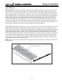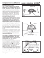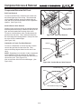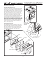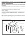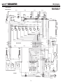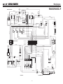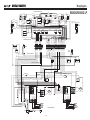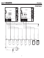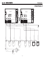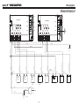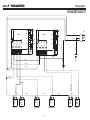
1
Technical Service Manual
Ranges
30
36
48
60
Inch
Inch
Inch
Inch
Rangetops
36 Inch
48 Inch
© WOLF APPLIANCE COMPANY, L.L.C.
2004 ALL RIGHTS RESERVED
JOB AID #803331
(Revision E - Aug. 2004)
General Information
RANGES & RANGETOPS
SECTION 1
GENERAL INFORMATION
1-1
General Information
RANGES & RANGETOPS
INTRODUCTION
This Wolf Appliance Technical Service Manual, Part #803331, has been compiled to provide the most recent technical service information about the Wolf Appliance Company, LLC. Ranges and Rangetops. This information will
enable the service technician to troubleshoot and diagnose malfunctions, perform necessary repairs, and return a
Wolf Range and/or Rangetop to proper operational condition.
The service technician should read the complete instructions contained in this Training/Service Manual before initiating any repairs on a Wolf Appliance.
* Some information in Section 2 (Theory of Operation) has been provided by the American Gas Association
and reprinted with AGA’s approval.
IMPORTANT SAFETY INFORMATION
TECHNICAL ASSISTANCE
Below are the Product Safety Labels used in this manual. The "Signal Words" used are WARNING and
CAUTION.
If you should have any questions regarding a Wolf
appliance and/or this manual, please contact:
Please note that these safety labels are placed in areas
where awareness of personal safety and product safety
should be taken and lists the precautions to be taken
when the signal word is observed.
INDICATES THAT HAZARDOUS OR UNSAFE PRACTICES COULD RESULT IN SEVERE PERSONAL
INJURY OR DEATH
Indicates that hazardous or unsafe practices could
result in minor personal injury or product and/or
property damage
In addition, please pay attention to the signal word
“NOTE”, which highlights especially important information within each section.
Wolf Appliance Company, LLC
ATTN: Service Department
P.O. Box 44988
Madison, WI 53744-4988
Customer Service & Parts / Warranty Claims
Phone #: (800) 332 - 9513
Technical Assistance
Phone #: (800) 919 - 8324
Customer Service & Technical Assistance
Facsimile #: (608) 441 - 5887
Parts / Warranty Claims
Facsimile #: (608) 441 - 5886
Office Hours:
7:00 AM to 7:00 PM Central Time
Monday through Friday
This manual is designed to be used by Authorized Service Personnel only. Wolf Appliance Company, LLC.
assumes no responsibility for any repairs made to Wolf appliances by anyone other than Authorized
Service Technicians.
The information and images are the copyright property of Wolf Appliance Company, LLC, an affiliate of Sub-Zero
Freezer Company, Inc. Neither this manual nor any information or images contained herein may be copied or used
in whole or in part without the express written permission of Wolf Appliance Company, LLC, an affiliate of Sub-Zero
Freezer Company, Inc. © Wolf Appliance Company, LLC all rights reserved.
1-2
General Information
RANGES & RANGETOPS
TABLE OF CONTENTS
Page #
Page #
Section 1 - General Information
Section 4 - Component Access and Removal Cont’d
Introduction......................................................................... 1-2
Important Safety Information.............................................. 1-2
Technical Assistance.......................................................... 1-2
Table of Contents............................................................... 1-3
Warranty Information......................................................... 1-5
Model Features.................................................................. 1-6
Model Key.......................................................................... 1-7
Top Configurations - 30”, 36” & 48” Ranges..................... 1-8
Top Configurations - 60” Range........................................ 1-9
Top Configurations - Rangetops....................................... 1-10
Switches & Lights............................................................ 4-9
Thermostat.......................................................................4-9
Components Below Roll Front.......................................... 4-10
Roll Front....................................................................... 4-10
Surface Burner Valve.....................................................4-10
Charbroiler/French Top Valve....................................... 4-10
Components Behind Lower Access Panel........................ 4-11
Lower Access Panel...................................................... 4-11
Door Switch................................................................... 4-11
Oven Burner Bi-Metal Valve.......................................... 4-11
Oven Burner Orifice....................................................... 4-11
Oven Compartment Components.....................................4-12
Oven Rack.................................................................... 4-12
Oven Rack Guide.......................................................... 4-12
Oven LIght Components............................................... 4-12
Oven Convection Fan................................................... 4-12
Oven Bottom Panel....................................................... 4-12
Oven Flame Deflector................................................... 4-13
Oven Burner Tube......................................................... 4-13
Oven Glow Coil Igniter.................................................. 4-13
Oven Broiler Glow Coil Igniter....................................... 4-14
Oven Infrared Broiler Burner......................................... 4-14
Oven Door Components................................................... 4-15
Door Assembly.............................................................. 4-15
Disassembling Door...................................................... 4-15
Side Panels & Components on Rear of Unit.................... 4-16
Side Panels................................................................... 4-16
Oven Bi-Metal Valve..................................................... 4-16
Oven Broiler Orifice....................................................... 4-16
Spark Module.................................................................4-16
Fan Relay.......................................................................4-16
Section 2 -Theory of Operation
Types of Fuel Gas.............................................................
Heating Value of Gas.........................................................
Specific Gravity of Gas......................................................
Principals of Gas Combustion...........................................
Burner Components...........................................................
Types of Burners................................................................
Simple Theory of Operation...............................................
2-2
2-2
2-2
2-3
2-4
2-5
2-6
Section 3 - Installation Information
Gas Pressure..................................................................... 3-2
Leak Testing....................................................................... 3-2
Electrical Requirements..................................................... 3-2
Unit Blocking....................................................................... 3-3
Unit Leveling....................................................................... 3-3
Range Installation Dimensions........................................... 3-4
Rangetop Installation Dimensions...................................... 3-5
Section 4 - Component Access and Removal
Important Warnings & Cautions.......................................... 4-2
Surface Burner Components.............................................. 4-3
Burner Grate & Rings...................................................... 4-3
Pressed Steel Top........................................................... 4-3
Surface Burner Body....................................................... 4-3
Surface Burner Orifice.................................................... 4-4
Surface Burner Electrode................................................ 4-4
Surface Burner Support................................................... 4-4
Infrared Charbroiler Components....................................... 4-5
Cover, Grate & Frame..................................................... 4-5
Charbroiler Orifice........................................................... 4-5
Charbroiler Burner Box................................................... 4-5
Charbroiler Sparker......................................................... 4-5
Infrared Griddle Components............................................. 4-6
Griddle Plate.................................................................... 4-6
Griddle Orifice................................................................. 4-6
Griddle Burner Box.......................................................... 4-6
Griddle Solenoid Valve................................................... 4-7
Griddle Thermostat......................................................... 4-7
Griddle Sparker................................................................4-7
French Top Components................................................... 4-8
Rings, Plate, Spacers & Burner Head............................. 4-8
French Top Burner Pan................................................... 4-8
French Top Electrode & Electrode Wire.......................... 4-8
French Top Orifice........................................................... 4-8
Control Panel Components................................................ 4-9
Control Panel................................................................... 4-9
Section 5 -Troubleshooting Guide
How to Use the Troubleshooting Guide............................. 5-2
Troubleshooting Guide Table of Contents.......................... 5-2
Troubleshooting Guide....................................................... 5-3
Section 6- Technical Data
Gas Pressure Table............................................................ 6-2
Orifice Chart....................................................................... 6-2
Checking Oven Ignition System......................................... 6-3
Section 7 - Wiring Diagrams
RANGES
Model R304....................................................................... 7-2
Model R366....................................................................... 7-3
Model R364C.................................................................... 7-4
Model R364C.................................................................... 7-5
Model
Model
Model
Model
Model
Model
Model
Model
1-3
R488........................................................................ 7-6
R486C..................................................................... 7-7
R486G..................................................................... 7-8
R484CG................................................................... 7-9
R484DC................................................................. 7-10
R484DG................................................................. 7-11
R484F.................................................................... 7-12
R482CF................................................................. 7-13
General Information
RANGES & RANGETOPS
Page #
Section 7 - Wiring Diagrams Cont’d
Model
Model
Model
Model
Model
Model
R606DC................................................................
R606DG................................................................
R606F....................................................................
R606CG.................................................................
R604CF.................................................................
R604GF.................................................................
7-14
7-15
7-16
7-17
7-18
7-19
Model
Model
Model
Model
RANGETOPS
RT366...................................................................
RT364C.................................................................
RT364G.................................................................
RT362F..................................................................
7-20
7-21
7-22
7-23
Model
Model
Model
Model
Model
Model
Model
Model
RT488...................................................................
RT486C.................................................................
RT486G.................................................................
RT484CG..............................................................
RT484DC..............................................................
RT484DG..............................................................
RT484F.................................................................
RT484F.................................................................
7-24
7-25
7-26
7-27
7-28
7-29
7-30
7-31
1-4
General Information
RANGES & RANGETOPS
WARRANTY INFORMATION
This page contains a summary of the 2 & 5 Year
Warranty that is supplied with every Wolf product, followed by details and notes about the warranties.
TWO & FIVE YEAR Warranty Summary
• Two year TOTAL PRODUCT warranty, parts and
labor.
• Limited Parts Only Warranty for the 3rd through 5th
year on the following parts only:
Gas Burners (excluding appearance)
• Stainless Steel (Classic, Platinum & Carbon) doors,
panels and product frames are covered by a limited
60 day parts and labor warranty for cosmetic
defects.
Serial
Plate
Warranty Details:
The warranty applies only to products installed for
normal residential use. The warranty applies only to
products installed in the United States or Canada.
Warranty Notes:
• All warranties begin at the time of the unit's initial
installation.
Figure 1-2. In most cases the serial plate is located
inside the top burner box, on the left inside panel of
ranges and rangetops. But, on models with the
French Top located on the left, the serial plate is on
the opposite (right) side.
• All Warranty and Service information collected by
Wolf Appliance Company, LLC. is arranged and
stored under the unit serial number and/or the customer's name. Please note that Wolf Appliance
LLC. requests that you have the model and serial
number available whenever contacting the factory or
parts distributor.
• See Figure 1-1 for typical serial plate layout.
• See Figures 1-2, 1-3 for serial plate location and
access.
Oven Broiler
BTU Rating
Gas Type
(Natural or LP)
Griddle BTU Rating
WOLF APPLIANCE COMPANY, LLC
WOLF GOURMET
GAS
OPEN
TOP
French Top
BTU Rating
Model Number
Location
Serial
Number
Location
INPUT RATING EACH
BURNER-BTU/HR.
NAT
GRIDDLE
16,000
FRENCH
TOP
15,000
VOLTS
115
FITCHBURG, WI
OVEN
BROILER
18,000
LEFT
OVEN
MAN.
PRESS.
10"
CHAR
BROILER
18,000
16,000
RIGHT
OVEN
30,000
30,000
ELECTRICAL RATING
PHASE
1
AMPS.
MINIMUM HORIZONTAL CLEARANCE FROM SI
ADJACENT COMBUSTIBLE CONSTRUCTION EX
12" FROM SIDE WALLS 0" FROM REAR WAL
ADJACENT COMBUSTIBLE MATERIALS BELOW
AND SIDE OF THE APPLIANCE: 0", MAXI
MINIMUM VERTICAL DISTANCE BETWEEN TH
MATERIALS ABOVE THE APPLIANCE : 30"
THE TOP BROILER GRID TO UNPROTECTED
MINIMUM HORIZONTAL DISTANCE BETWEEN
EITHER SIDE OF THE APPLIANCE SHALL N
APPLIANCE. TO BE USED IN CONJUNCTIO
COOKING UTENSILS SHALL NOT BE USED O
MINIMUM HORIZONTAL CLEARANCE FROM IS
COMBUSTIBLE SIDE AND BACK WALL IS 12
6
"
HP
.05
MODEL
BD
60
Charbroiler
BTU Rating
Right Oven
BTU Rating
E
3".
Figure 1-3. To access the serial plate, remove the
grates from the pressed steel top. Remove the
burner heads and then use the “S” hook supplied
with the unit to remove the pressed steel top.
Left Oven
BTU Rating
SEQ.
ML
SERIAL
NO.
ANSI Z21.1
HERTZ
DES AND BACK OF APPLIANCE TO
TENDING 18" ABOVE THE COOKING SURFAC
L. MINIMUM CLEARANCE BETWEEN
THE COOKING SURFACE AND THE BACK
MUM DEPTH FOR OVERHEAD CABINETS IS 1
E COOKING SURFACE AND COMBUSTIBLE
. MINIMUM VERTICAL DISTANCE BETWEEN
OVERHEAD COMBUSTIBLE SURFACES 36".
OVERHEAD CABINETS INSTALLED TO
OT BE LESS THAN THE NOMINAL WIDTH OF
N WITH A SUITABLE VENT HOOD ONLY.
N AN OPEN TOP BROILER SECTION.
LAND INSTALLATION COOKTOP TO
Water Column
Pressure
-
"HOUSEHOLD GAS COOKING APPLIANCES"
"CGA IR 58, 1995"
800117-A
Figure 1-1. Typical Serial Plate Layout
1-5
General Information
RANGES & RANGETOPS
MODEL FEATURES
All ranges:
Oven burners input rated at 18,000 and 30,000 BTU. Infrared Oven Broiler input rated at 18,000 BTU.
Some models:
Charbroiler on rangetop rated at 16,000 BTU input. Griddle on rangetop rated at 18,000 BTU input. French Top on
rangetop rated at 15,000 BTU input.
RANGE FEATURES:
•
•
•
•
•
•
•
•
•
•
•
•
•
•
•
•
Natural or LP gas models
Classic stainless steel exterior
Large red control knobs with four position settings (optional blackknobs available)
Chrome bezels surround all knobs
Dual brass burners with automatic re-ignition at all settings
Cast iron porcelain coated grates
Optional S-grates available
Stainless steel drip tray on ball bearing slides
Door windows and interior lights in ovens
Porcelain oven interior
3" (76 mm) adjustable stainless steel legs in front and adjustable rear casters
Full side panels and skirt
High altitude conversion kit available
Optional risers – 5" (127 mm), 10" (254 mm) and 20" (508 mm) with shelf
Two and five year residential warranty
CSA certified for US and Canada
RANGETOP FEATURES:
•
•
•
•
•
•
•
•
•
•
•
•
•
Natural or LP gas models
Classic stainless steel exterior
Large red control knobs with four position settings (optional black knobs available)
Chrome bezels surround all knobs
Dual brass burners with automatic re-ignition at all settings
Cast iron porcelain coated grates
Optional S-grates available
Stainless steel drip tray on ball bearing slides
Low profile stainless steel island trim
High altitude conversion kit available
Optional 10-1/2" (267 mm) riser
Two and five year residential warranty
CSA certified for US and Canada
1-6
General Information
RANGES & RANGETOPS
MODEL NUMBER KEY
Refer to this key for an example of the model numbers.
Model:
R
60 6
CG - LP
Product Type
R
Range
RT
Rangetop
Size
30
30 - inch wide unit
36
36 - inch wide unit
48
48 - inch wide unit
60
60 - onch wide unit
Surface Burners
2
2 - open burners
4
4 - open burners
6
6 - open burners
8
8 - open burners
Model Features
C
2 - open burners
G
4 - open burners
F
6 - open burners
DG
Double Griddle (22”)
DC
Double Charbroiler (22”)
Fuel
LP
Propane Gas (Propane Gas will be indicated by -LP at the end of the model number.
Example: R606CG-LP-LP)
NOTE: If model number doesn’t have -LP at the end, unit is Natural Gas.
1-7
General Information
RANGES & RANGETOPS
TOP CONFIGURATIONS OF 30”, 36” and 48” RANGES
Configuration
New Model #
Old Model #
Description
R304
AS30Ki
4 Open Burners
R366
AS36Ki-2
6 Open Burners
R364C
AS36Ki-7
4 Open Burners - w/11" Charbroiler
R364G
AS36Ki-6
4 Open Burners - w/11" Griddle
R488
PS488K
8 Open Burners
R486C
PS486BK
6 Open Burners - w/11" Charbroiler
R486G
PS486GK
6 Open Burners - w/11" Griddle
R484CG
PS48GBK
4 Open Burners - w/11" Charbroiler & 11"Griddle
R484DC
PS484BK
4 Open Burners - w/22" Charbroiler
R484DG
PS484GK
4 Open Burners - w/22" Griddle
R484F
PS484FK
4 Open Burners - w/22" French Top
R482CF
PS48FBK
2 Open Burners - w/11" Charbroiler & 22" French Top
NOTE: (- LP) Following the New Model Number signifies Propane Gas
1-8
General Information
RANGES & RANGETOPS
TOP CONFIGURATIONS OF 60” RANGE
Configuration
New Model #
Old Model #
Description
R606DC
S60BKK
6 Open Burners - w/22" Charbroiler
R606DG
S60GKK
6 Open Burners - w/22" Griddle
R606F
S60FKK
6 Open Burners - w/22" French Top
R606CG
S60GBKK
6 Open Burners - w/11" Charbroiler & 11" Griddle
R604CF
S60FBKK
4 Open Burners - w/11" Charbroiler & 22" French Top
R604GF
S60FGKK
4 Open Burners - w/11" Griddle & 22" French Top
NOTE: (- LP) Following the New Model Number signifies Propane Gas
1-9
General Information
RANGES & RANGETOPS
TOP CONFIGURATIONS OF 36” & 48” RANGETOPS
Configuration
New Model #
Old Model #
Description
RT366
SB366
6 Open Burners
RT364C
SB364B
4 Open Burners - w/11" Charbroiler
RT364G
SB364G
4 Open Burners - w/11" Griddle
RT362F
SB362F
2 Open Burners - w/22" French Top
RT488
SB488
8 Open Burners
RT486C
SB486B
6 Open Burners - w/11" Charbroiler
RT486G
SB486G
6 Open Burners - w/11" Griddle
RT484CG
SB48GB
4 Open Burners - w/11" Charbroiler & 11"Griddle
RT484DC
SB484B
4 Open Burners - w/22" Charbroiler
RT484DG
SB484G
4 Open Burners - w/22" Griddle
RT484F
SB484F
4 Open Burners - w/22" French Top
RT482CF
SB48FB
2 Open Burners - w/11" Charbroiler & 22" French Top
NOTE: (- LP) Following the New Model Number signifies Propane Gas
1-10
RANGES & RANGETOPS
Theory of Operation
SECTION 2
THEORY OF OPERATION
2-1
Theory of Operation
RANGES & RANGETOPS
THEORY OF OPERATION
A service technician should understand how a gas appliance operates before attempting to service the appliance.
This section provides descriptions of the different types of fuel gases and explains gas heating values. A definition
of specific gravity of gas is given along with its characteristics and effects. Gas combustion principals are explained
and gas burner components are described and illustrated. The end of this section contains illustrations which
demonstrate basic cooking appliance theory of operation.
Types of Fuel Gas:
Gases used to supply heat energy are called fuel gases. Common fuel gases are not simply one kind of hydrocarbon, they are mixtures of hydrocarbon gases. They contain other gases as well, such as free hydrogen, carbon
dioxide and nitrogen. As an example natural gas might contain 85% methane, 12% ethane and 3% of other gases.
The presence of each of these gases in the fuel gas has some effect on the nature of the gas.
Some common fuel gasses are methane [CH4], ethane [C2H6], Propane [C3H8] and butane [C4H ]. Propane and
butane are nearly odorless. Natural gas that is processed to remove condensables and moisture, has little or no
odor and no color. Odorants are added to natural gas before distribution to aid in leak detection. A common odorant
used is a colorless liquid containing sulfur compounds.
10
Heating Value of Gas:
Heat energy produced when burning a fuel gas is commonly expressed in British Thermal Units (BTU). One BTU of
heat will raise the temperature of one pound of water one degree Fahrenheit.
The more carbon and hydrogen atoms in each molecule of a fuel gas, the higher its heating value. Natural gas
which is high in methane has a heating value of about 950 to 1150 BTU per cubic foot. The variance is due to the
various other substances found in natural gases. The more ethane, propane or butane in the gas raises the heating
value. Propane, or LP gas, has a heating value of about 2500 BTU per cubic foot, and butane about 3200 BTU per
cubic foot.
Specific Gravity of Gas:
The specific gravity of a gas is the weight of one cubic foot, or the gas compared to one cubic foot of dry air. When
stating the specific gravity of a gas, a pressure and temperature must be clearly stated. In the gas industry, the
standard conditions of pressure and temperature are 30.0 inches of mercury and 60° F. A pressure of 30.0 inches of
mercury will sustain a column of mercury 30 inches high in a tube with a vacuum on top of the column. Since air is
used as the reference, its specific gravity is always 1.0. This value of 1.0 has no direct physical meaning with
regard to air, such as its density. It is only a relative number or ratio used to express specific gravity of other gases.
The specific gravity of a gas will determine if the gas will rise or fall when released into the air. Natural gas will rise
since its specific gravity is less than 1.0 at 0.4 to 0.8. Propane has a specific gravity of 1.5 and butane 2.0. These
gases will fall when released into the air. They sometimes collect in low spots into pools which become a hazard if
open flames are present.
In addition, specific gravity has two other characteristics. It has an important effect on the flow of gases through orifices, and hence the rating of the burners. Gas flow through an orifice is dependent upon the orifice size and the
gas pressure upstream of the orifice. More of a lighter gas will flow through a given orifice size than a heavier gas
at the same gas pressure. This effect is taken into account in tables and calculators used to select orifice sizes for
burners.
The gas flow in pipes is also affected by specific gravity. At a given pressure at a pipe inlet, more lighter gas will
flow through a pipe than a heavier gas.
2-2
RANGES & RANGETOPS
Theory of Operation
Principals of Gas Combustion:
Combustion - When oxygen acts with a substance to produce large amounts of heat rapidly.
Requirements for Combustion - There are three required elements for combustion to occur; Fuel (Gas), Oxygen
(Air) and Heat (Ignition Temperature, which for gas is between 1100°F/593°C and 1200°F/649°C). All must be present. Removing any one of the three and combustion will cease.
Chemistry of Combustion - Combustion of gas is a chemical reaction between fuel gas and oxygen. The basic
elements of common fuel gasses are hydrogen [H] and carbon [C]. When hydrogen burns, water vapor [H2O] is produced. Complete burning of carbon in fuel gases form carbon dioxide [CO2] and water vapor [H2O].
Controlled Combustion - Controlled combustion takes place when gas and air are supplied at proper rates to
assure complete combustion of the gas in a steady flame. When a gas appliance is operating properly, burning
starts at the burner ports. Gas flow is controlled by gas orifice size and gas pressure upstream of the orifice. Air is
mixed with the gas before it passes through the burner ports. This added air is called “Primary Air”. The remaining
air required for complete combustion is supplied to the burner at the point of combustion and is called “Secondary
air”.
Adjustments of the gas-to-air ratio and the secondary air supply is the key to obtaining stable blue flames at a burner. Proper amounts of primary and secondary air are required for quiet and efficient burner operation and for complete combustion of the gas. Air Shutters or other devices provide control of primary air. Inlet opening and flue outlets control Secondary Air flow.
Total air - In an ideal situation, primary and secondary air is all that is needed (for the oxygen required) to burn the
gas, but some additional air is required to assure complete burning of the gas. The total air, “primary”, “secondary”
and “excess” are expressed as percentages of the amount needed. About ten cubic feet of air is required to completely burn one cubic foot of gas. For this reason an appliance should not be operated in an air tight home.
Limits of Flammability - Not all air-to-gas mixtures will burn. Mixtures with 0% - 4% natural gas in air are too lean
to burn. Mixtures of 4% - 14% natural gas in air can burn with a controlled flame. Flammability limits come into play
when primary air adjustments are made on burners. If too much primary air is used, the mixture may become too
lean and fall below flammability limits, thus preventing combustion.
Incomplete Combustion (Causes and Effects) - To obtain complete combustion, sufficient amounts of air must be
supplied to the process. This air must have a reasonably normal oxygen content. Complete burning of gas produces harmless carbon dioxide gas and water vapor. If the air supply is insufficient, incomplete combustion occurs
resulting in the formation of toxic byproducts, such as carbon monoxide [CO] or aldehydes.
Carbon monoxide is colorless and odorless. Inhaling carbon monoxide in sufficient quantities could cause death by
reducing oxygen levels in the blood.
Aldehydes, which are equally dangerous, have a sharp and penetrating odor which is easily detected by smell at
very low concentrations. The odor caused by aldehydes should not be confused with odorants added to natural gas.
The absence of aldehydes does not assure that carbon monoxide is not present. However, if the odor of aldehydes
is present, then carbon monoxide is virtually always present.
Gas Burner Operation - A gas burner is a device to burn gas under control in order to produce useful heat.
Primary air is brought into the burner from outside of the appliance at atmospheric pressure. The gas jet streaming
from the orifice draws primary air with it into the burner.
The gas/air mixture, combined with a spark at the burner port(s) and the secondary air creates a controlled burn.
2-3
Theory of Operation
RANGES & RANGETOPS
Burner Components:
Gas Orifice - An opening or hole which regulates or limits the amount of gas flowing to a burner. Gas flow rate (volume) depends on the size of the orifice (hole) and the gas pressure at the inlet of the orifice.
Air Shutter - This is used to adjust the size of the primary air inlet area and therefore controls primary air flow.
Venturi Tube (Open Surface Burner & French Top Only) - A section of pipe at the inlet of the burner body that narrows and then flares out again. This tube helps maintain a proper and constant primary air injection.
Mixing Tube/Throat - Serves to carry the gas/air mixture from the venturi tube to the burner body.
Burner Body - The accumulation chamber below the burner base which allows the gas and air to mix together fully.
Burner Base/Cross Over Ring - The component below the burner ring which carries the gas/air mixture to the
burner ring.
Burner Ring/Burner Head - The component containing the burner ports where the gas/air mixture ignites. The
burner ports are distributed in a useful pattern to optimize heat transfer. The flames should be spread so they can
be easily reached by secondary air and provide a stable blue flame.
Burner Ring
Venturi Tube
Burner Ports
Burner Base
Gas Orifice
Mixing Tube
Burner Body
Figure 2-1. Cut-away View of Open Surface Burner Components
2-4
Air Shutter
RANGES & RANGETOPS
Theory of Operation
Types of Burners:
Blue Flame Burners - All Wolf open surface burners, French Top burners and the "U" burner in the oven are blue
flame burners. With this type of burner, primary air is mixed with the fuel gas before the gas reaches the burner
ports. An orifice is used to regulate gas flow to the burner. Air which is mixed with the gas inside the burner body
enters through openings in the burner body. A shutter or venturi tube is used to adjust the size of these openings
and control the primary air. Gas and air mix in the mixing tube or throat, which then exits the burner ports where it is
ignited. Secondary air is air from around the flames. The flame produced has several zones, each represents a
stage in burning of the gas. The burner tip has a thin dark blue cone called the inner or primary cone. A lighter
cone called the outer cone, surrounds the inner cone. Air around the flame diffuses into the flame to burn at the
outer cone. If conditions are perfect, products from the inner cone burn here. The final products of burning are carbon dioxide and water vapor. An outer mantle surrounds the outer cone where burning is usually completed. It is
nearly invisible and glows only because of the high temperature of the final combustion.
Infrared Burners - Wolf gas ranges also use two types of infrared burners. The under-fired application for the charbroiler and the griddle uses a porous refractory ceramic tile burner. (See Figure 2-2) An over-fired screen type
burner is used in the oven broiler. With these two types of burners, a substantial amount of energy output is in the
form of infrared radiant energy. With infrared heat, thermal energy is transmitted through space without heating the
medium through which it travels. Infrared energy is usually not affected by air flowing between the burners and
heated surfaces because of the burner’s numerous and tiny flames. This type of heat is very efficient and compact.
The under-fired refractory infrared burner requires 100 percent primary air and is designed to have a hot glowing
burner surface. The flame burns close to the burner surface at a high temperature. In the case of the over-fired
screen type oven broiler, it does not require 100 percent primary air since sufficient amounts of secondary air can
easily reach the screen where the gas is burning.
NOTE: There is no shutter on infrared burners for adjusting the primary air and there is no change in orifice size for
different altitude.
Porous Ceramic Surface
Figure 2-2. Infrared Burner (Under-fired Application for the Charbroiler or Griddle Shown)
2-5
Theory of Operation
RANGES & RANGETOPS
Gas Cooking Appliance Simple
Theory of Operation:
Regulator
Gas arrives at the house through pipes
(usually under ground) in the form of natural gas or liquid propane gas. This gas
supply can be from a local utility source or
a tank source.
A "Gas Pressure Regulator" on the appliance is connected to the gas supply line of
the house. The regulator maintains the
gas pressure in the appliance at a given
point below the house gas pressure.
(See Figure 2-3)
GAS
GAS
Gas from
house supply
Figure 2-3. Gas Pressure Regulator
The gas passes through the regulator and
is piped to a valve. This valve can be
opened in varying amounts, to allow a specific quantity of gas to pass through. This
is how the size of the flame is adjusted.
(See Figure 2-4)
Valve
GAS
GAS
After the valve, the gas is piped to a “gas
orifice,” which is an opening of very small
diameter. The gas is pushed through the
small diameter of the gas orifice, so when
it exits it is under high velocity. This high
velocity stream of gas causes a drop in
Figure 2-4. Gas Valve
pressure around itself. The low pressure
around the stream of gas draws the
nearby air, referred to as "primary
air," with it into the venturi tube.
Primary air is drawn to low pressure
around stream of gas exiting orifice
(See Figure 2-5)
(Continued on next page)
GAS
Venturi Tube
Orifice
Figure 2-5. Gas Orifice
2-6
Control Knob
Theory of Operation
RANGES & RANGETOPS
The gas and air travel through the
venturi tube and the mixing tube,
also called the throat, where the
gas and air begin to mix together.
The gas and air mixture then enters
into the base of the burner. The
large volume of the base allows the
gas and air to expand, mixing them
together thoroughly.
(See Figure 2-6)
Mixing Tube
GAS & AIR MIX
Gas & air exits burner ports,
mixes with secondary air
and is ignited by a spark
GAS & AIR MIX
GAS
With the proper gas and air mixture,
a flame of natural gas should be
blue with a deep blue inner cone
and have no trace of yellow flame.
(See Figure 2-8)
With liquid propane gas some
orange tipping is acceptable.
In both cases, the flame should be
odorless and completely free of
dangerous gases.
Figure 2-6. Venturi, Mixing Tube & Burner Body
Figure 2-7. Gas/Air Exit Burner Ports and is Ignited
Proper flame has dark blue
inner cone surrounded by
lighter blue cone
GAS & AIR MIX
GAS
The gas and air mixture then exits
out of the burner ports where it further mixes with “secondary air.”
A spark is introduced to this gas
and air mixture as it leaves the
burner ports, which causes ignition.
(See Figure 2-7)
GAS
Venturi Tube
Figure 2-8. Proper Flame
2-7
Theory of Operation
RANGES & RANGETOPS
2-8
Installation Information
RANGES & RANGETOPS
SECTION 3
INSTALLATION
INFORMATION
3-1
Installation Information
RANGES & RANGETOPS
INSTALLATION INFORMATION
Leak Testing:
This section of the manual covers some of the installation issues that a service technician may need to know
when servicing a Wolf range or rangetop. If additional
installation information is needed after reviewing this
section of the manual, please refer to the installation
guide or contact the Wolf Appliance Customer Service
Department.
NEVER USE OPEN FLAMES TO CHECK FOR GAS
LEAKS. ONLY USE A COMMERCIAL LEAK DETECTION SOLUTION OR SOAP SUDS AROUND GAS
CONNECTIONS TO CHECK FOR LEAKS. DO NOT
USE LIQUID NEAR VALVE STEMS.
Gas Pressure:
Electrical Requirements:
NOTE: All Wolf gas appliances are manufactured to
work with natural gas, but Wolf gas appliances can be
converted to work with LP gas (Liquid Propane gas).
A Wolf gas appliance requires 110 to 120 volts AC and
a 15 ampere dedicated circuit breaker to operate
properly.
The power supply cord provided on the appliance is
equipped with a 3-prong (grounding) plug. The installation site must be equipped with a properly grounded 3prong receptacle. If the electric receptacle or the power
cord are not properly grounded and polarized, this
could cause a shock hazard and the appliance may
experience ignition problems. (See Figure 3-1)
Natural Gas Manifold Pressure
Standard natural gas orifices on the appliance are set
for 5” WC (Water Column Pressure).
Liquid Propane Manifold Pressure
The standard propane gas orifices in a conversion kit
will be set for 10” WC (Water Column Pressure).
Gas Supply Pressure
• Maximum line pressure for natural gas and LP is 14”
WC; 1/2 psi (3.5 kPa).
• Minimum line pressure for natural gas is 7” WC.
• Minimum line pressure for LP gas is 11” WC.
Neutral
Line
Voltage
(Power)
Gas Pressure Regulator
To control and maintain a uniform gas pressure in the
gas manifold, Wolf gas appliances must be connected
to the gas supply line through a pressure regulator.
The burner orifices are sized for the pressure delivered
by the regulator. Never attempt to operate a Wolf gas
appliance without the use of the proper pressure regulator.
Ground
The maximum gas supply pressure to the regulator
should never exceed 14” WC (Water Column
Pressure); 1/2 psi (3.5kPa).
Figure 3-1. Proper Polarity at Electric Receptacle
TO AVOID SHOCK HAZARD, NEVER REMOVE THE
GROUND PRONG FROM THE PLUG OF THE POWER
SUPPLY CORD.
3-2
Installation Information
RANGES & RANGETOPS
Unit Blocking:
Unit Leveling:
Wolf ranges can tip forward under certain load conditions. The anti-tip wall bracket must be attached to the
wall behind the appliance so that it is directly above the
bottom rear brace when the range is fully installed.
(See Figure 3-2)
Wolf ranges can be leveled at the front by adjusting the
3" (76 mm) adjustable front legs. (See Figure 3-3)
In order to level the rear of the unit, use the caster
wrench (p/n 803239), to rotate the 2-5/16" (59 mm) nut
clockwise to raise or counterclockwise to lower the unit.
(See Figure 3-4)
Use shims to level a wolf rangetop.
Anti-Tip
Bracket
Figure 3-2. Anti-Tip Wall Bracket Installation
UP
Wall
Side Panel
Figure 3-3. Unit Leveling, Front Leveling Leg
Anti-Tip
Bracket
61/2" min.
to floor
REAR CASTER
ADJUSTMENT NUT
Rear
Channel
Brace
HEIGHT ADJUSMENT
WITH CASTER WRENCH
Floor
Figure 3-2. Anti-Tip Wall Bracket Installation
Figure 3-4. Unit Leveling, Rear Caster Adjustment
3-3
Installation Information
RANGES & RANGETOPS
INSTALLATION DIMENSIONS
28 3/8" (721)
OVERALL DEPTH
RANGES
27 1/4" (692)
9 1/4"
1 3/4"
(235)
(44)
20" (508)
RISER
10" (254)
RISER
5" (127)
RISER
COOKING
SURFACE
56 3/4"
ISLAND OR PENINSULA INSTALLATION
(1441)
46 3/4"
37"
(1187)
(940)
35 1/2"
41 3/4"
(902)
(1060)
36"
(914)
36"
(914)
191/8" (486)
43 3/8" (1102)
2 1/2"
(64)
A
3" (76) FRONT LEGS WITH
1" (25) HEIGHT ADJUSTMENT
OVERALL WIDTH
24 1/2" (622)
REAR CASTERS ALLOW
1" (25) HEIGHT ADJUSTMENT
25 1/4"(641)
COMBUSTIBLE CONSTRUCTION
VENTILATION HOOD
13" max
(330)
CABINET
DEPTH
*30" min (762)
SURFACE BURNERS AND
GRIDDLE
ISLAND INSTALLATION:
NO SIDE WALL OR REAR WALL
ABOVE COOKING SURFACE
*36" min (914)
30" (762) TO 36" (914)
COOKING SURFACE TO
BOTTOM OF
VENTILATION HOOD
ALL 60" (1524) RANGES
CHARBROILER
6" min
(152)
TO
COMBUSTIBLE
MATERIALS
*44" min (1118)
6" min
(152)
TO
COMBUSTIBLE
MATERIALS
COOKING
SURFACE
18" min (457)
TO COOKING
SURFACE
27 1/4" (692)
PENINSULA INSTALLATION:
NO SIDE WALL ABOVE
COOKING SURFACE
*** ISLAND
INSTALLATION
COOKING SURFACE
37"
B
(940)
FINISHED ROUGH OPENING WIDTH
LOCATION OF
ELECTRICAL
D
E
8"
(203)
E
36" max
36"
(914)
(914)
LOCATION OF
2" **GAS SUPPLY
(51)
5 1/2"
(140)
C
G
3"
5"
* MINIMUM DISTANCE FROM COOKING SURFACE
(127)
TO BOTTOM OF COMBUSTIBLE CONSTRUCTION
** LOCATION OF GAS SUPPLY EXTENDS
(76)
3" (76) ON FLOOR FROM BACK WALL
NOTE: Dimensions in parentheses are in millimeters.
30" Range
A Overall Width of Range (width may vary to +1/4")
B Finished Rough Opening Width
36" Range
*** 12" (305) MINIMUM CLEARANCE TO
COMBUSTIBLE MATERIALS Ð
0" (0) TO NON-COMBUSTIBLE MATERIALS
48" Range
60" Range
48"(1219)
60"(1524)
30"(762)
36"(914)
30 1/4"(768)
36 1/4" (921)
48 1/4"(1226)
60 1/4"(1530)
C Location of Gas Supply (within shaded area)
12"(305)
10"(254)
12"(305)
12"(305)
D Location of Electrical
10"(254)
10"(254)
26"(660)
10"(254)
E Location of Electrical (within shaded area)
12”(305)
12"(305)
12"(305)
12"(305)
3-4
Installation Information
RANGES & RANGETOPS
INSTALLATION DIMENSIONS
27 1/4" (692)
OVERALL DEPTH
(to knobs)
1 3/4"
(44)
RANGETOPS
10 1/2" (267)
RISER
COOKING
SURFACE
20"
ISLAND OR PENINSULA
INSTALLATION
(508)
10 1/2" (267)
9 1/2" (241)
9 1/2" (241)
2 3/4"
(70)
(to knobs)
A
OVERALL WIDTH
24" (610)
COMBUSTIBLE CONSTRUCTION
VENTILATION HOOD
13" max
(330)
CABINET
DEPTH
*30" min (762)
SURFACE BURNERS
AND GRIDDLE
30" (762) TO 36" (914)
COOKING SURFACE TO
BOTTOM OF
VENTILATION HOOD
*36" min (914)
6" min
CHARBROILER
(152)
TO
COMBUSTIBLE
MATERIALS
ISLAND INSTALLATION:
NO SIDE WALL OR REAR WALL
ABOVE COOKING SURFACE
18" min (457)
TO COOKING
SURFACE
6" min
(152)
TO
COMBUSTIBLE
MATERIALS
PENINSULA INSTALLATION:
NO SIDE WALL ABOVE
COOKING SURFACE
** ISLAND
INSTALLATION
COOKING SURFACE
9 1/2" (241)
3/4" (19) PLATFORM
TOP VIEW
OF PLATFORM
1/2"
(13)
BACK WALL
3" (76)
G
E
C
2 3/4"
14"
(70)
(356)
3/4" (19) PLATFORM
36" max
LOCATE ELECTRICAL AND
GAS SUPPLY WITHIN
SHADED AREA THROUGH
BOTTOM OF PLATFORM
24" (610)
(914)
C
B
** 12" (305) MINIMUM CLEARANCE TO
FINISHED ROUGH OPENING WIDTH
COMBUSTIBLE MATERIALS Ð
0" (0) TO NON-COMBUSTIBLE MATERIALS
* MINIMUM DISTANCE FROM COOKING SURFACE TO BOTTOM OF COMBUSTIBLE CONSTRUCTION
NOTE: Dimensions in parentheses are in millimeters.
36" Rangetop
48" Rangetop
A Overall Width of Rangetop
36" (914mm)
48" (1219mm)
B Finished Rough Opening Width
361/4" (921mm)
481/4" (1226mm)
C Location of Gas Supply and Electrical
8" (203mm)
16" (406mm)
3-5
Installation Information
RANGES & RANGETOPS
3-6
Component Access & Removal
RANGES & RANGETOPS
SECTION 4
COMPONENT
ACCESS AND REMOVAL
4-1
Component Access & Removal
RANGES & RANGETOPS
COMPONENT ACCESS AND REMOVAL
This section explains how to access and remove components from a Wolf range and rangetop.
NOTE: Before attempting to access or remove any components from a Wolf appliance, take note of the WARNINGS and CAUTIONS below.
TO AVOID SERIOUS BURNS AND/OR EXPLOSIONS, KEEP COMBUSTIBLES AWAY FROM THE APPLIANCE
WHENEVER A FLAME IS PRESENT. KEEP IN MIND THAT OVEN SURFACES AND COMPONENTS GET HOT
DURING USE OF THE APPLIANCE. IF THE OVEN IS SWITCHED ON DURING SERVICE, KEEP YOUR FACE
AWAY FROM THE DOOR WHEN OPENING IT.
TO AVOID ELECTRIC SHOCK, POWER TO THE UNIT MUST BE DISCONNECTED WHENEVER ACCESSING
AND/OR REMOVING COMPONENTS POWERED BY ELECTRICITY OR COMPONENTS NEAR OTHER
ELECTRICAL COMPONENTS.
IF IT IS NECESSARY TO REMOVE A UNIT FROM ITS INSTALLATION, REMEMBER THAT THE UNIT COULD
TIP FORWARD WHEN PULLED FORWARD BEYOND THE ANTI-TIP COMPONENTS, RESULTING IN SERIOUS
INJURY OR DEATH. PULLING A UNIT FROM ITS INSTALLATION SHOULD ONLY BE PERFORMED BY AN
AUTHORIZED SERVICE TECHNICIAN OR INSTALLER.
WHEN REASSEMBLING GAS SUPPLY LINE TO REGULATOR, ONLY PIPE THREAD COMPOUND SHOULD BE
USED. DO NOT USE TEFLON TAPE TO SEAL GAS PIPE CONNECTIONS.
WHEN REASSEMBLING REGULATOR TO MANIFOLD, ONLY PIPE THREAD COMPOUND SHOULD BE USED.
DO NOT USE TEFLON TAPE TO SEAL GAS CONNECTIONS.
-
If removing or disconnecting the door spring, remember it could recoil quickly when released.
4-2
Component Access & Removal
RANGES & RANGETOPS
Surface Burner Components:
Burner Grate
Surface Burner Grate, Inner Burner, Outer Burner
Ring & Outer Burner Base Removal
Inner Burner
• Lift the burner grate from the pressed steel top.
• Lift the inner burner from the inner burner base.
• Lift the outer burner ring from the outer burner base.
• Lift the outer burner base from the burner body.
(See Figure 3-1)
Outer Burner Ring
Outer Burner Base
Surface Burner Pressed Steel Top Removal
Pressed Steel Top
After the grates are removed, the pressed steel top can
be removed by placing the vinyl coated end of the “S”
hook removal tool (supplied with the unit) into one of
the oblong holes in the steel top and lifting up. (See
Figure 3-2)
Figure 3-1. Components that Lift Off
Surface Burner Body Removal
In order to remove the Burner Body, the components
listed above will need to be removed first, and the unit
will need to be pulled from its installation so that the
back panel can be removed.
Once the back panel is removed, disconnect the appropriate electrode wire from the spark module and clip
any cable ties around the wire being removed.
With wrenches, disconnect the inner burner gas supply
line from the burner body. (See Figure 3-3)
With one wrench on the outer burner orifice holder, use
another wrench to disconnect the flexible gas line which
supplies the outer burner. (See Figure 3-4)
Extract the burner body mounting screws with a Phillips
head screwdriver and lift the burner body from the
appliance, along with the electrode wire.
NOTE: The inner burner base can be removed from
the burner body with a large Allen wrench.
“S” Hook
Figure 3-2. Steel Top Removal
Hold flat portion of orifice
holder with wrench.
Disconnect inner burner
supply line here.
Use another wrench
to disconnect flex tube
connection.
Figure 3-3. Disconnect Inner Burner Supply Line
Figure 3-4. Disconnect Outer Burner Supply Line
4-3
Component Access & Removal
RANGES & RANGETOPS
Surface Burner Orifice Removal
Outer - The outer burner orifice is hex shaped and
attached to the orifice holder near the inlet of the venturi tube. Use a wrench to remove it. (See Figure 3-5)
Inner burner orifice
Inner - The inner burner orifice is small and bellshaped. It is located inside the inner burner mixing
tube and held in place by the gas line brass fitting. To
remove the orifice, use a wrench to disconnect the
brass fitting from the mixing tube. Then, use a flatblade screwdriver to reach into the mixing tube and
knock the orifice out. (See Figure 3-5)
Outer burner orifice
Surface Burner Electrode Removal
Burner Body
Figure 3-5. Surface Burner Orifice Removal
The surface burner electrode is attached to the burner
body using an E-ring and a retaining spring at the bottom side of the burner body. The electrode wire is
inserted down through a mounting hole in the burner
body and through the retaining spring. When the electrode is installed down fully into the mounting hole, the
retaining spring is pushed up tight to the bottom of the
burner body and compressed slightly. The E-ring is
placed behind the retaining spring into a groove on the
base of the electrode. (See Figure 3-6) The electrode
wire is then inserted into a wire sleeve and routed to
the spark module which is located on the back side of
the unit.
In order to remove a surface burner electrode, the unit
must be pulled from its installation and the back panel
must be removed. Once the back panel is removed,
disconnect the appropriate electrode wire from the
spark module. Then, using an 10mm allen wrench,
remove the inner burner base.
Access the bottom of the burner body and locate the Ering at the base of the electrode. Remove the E-clip
using a small flat-blade screwdriver. Then, pull the
electrode and its wire out form the wire sleeve and up
through the burner body. (See Figure 3-6)
Electrode
Burner Body
Retaining Spring
E-Ring
Electrode Wire
Wire Sleeve
Figure 3-6. Surface Burner Electrode Removal
Surface Burner Support Removal
The burner body will need to be disconnected from the
top of the surface burner support before attempting to
remove the support. But, do not extract the support
mounting screws until a pencil has been used to mark
the position of the locator holes and the edge of the
support at front and rear. (See Figure 3-7)
NOTE: These markings will assist in proper location of
the support when reinstalling. Failure to mark the location before removal could cause burner alignment problems when reinstalling the support.
After marking the support location, use a Phillips head
screwdriver to remove the four mounting screws, two at
front and two at rear. Then lift the support from the top
of the appliance.
Before removing burner support, mark
the location of the hole and the edge
of the support at the front and back.
Figure 3-7. Mark Location Of Burner Support
4-4
Component Access & Removal
RANGES & RANGETOPS
Infrared Charbroiler Components:
Cover Spacer
Infrared Charbroiler Cover, Cover Spacer, Grate,
Screen, Blank-off Plate & Charbroiler Frame
Removal
Cover
•
•
cover from the broiler frame.
cover spacer from the broiler
Grille
grille from the broiler frame.
screen from the burner box.
blank-off from the burner box.
frame from the top of the unit.
Blank-off Plate
•
•
•
•
Lift the Charbroiler
Lift the Charbroiler
frame.
Lift the Charbroiler
Lift the Charbroiler
Lift the Charbroiler
Lift the Charbroiler
(See Figure 3-8)
Screen
Infrared Charbroiler Orifice Removal
The orifice is located in the brass orifice elbow, which is
threaded into the orifice holder at the front of the burner
box.
NOTE: It is possible to access and remove the orifice
without lifting out the infrared burner box, however lifting
the box out first will make the task easier.
To remove the orifice, first remove the heat shield and
disconnect the gas line from the brass orifice elbow.
Then, unscrew the elbow from the orifice holder, and
extract the orifice from the elbow with wrenches. (See
Figure 3-9)
Charbroiler Frame
Figure 3-8. Components that Lift Off
Infrared Charbroiler Burner Box Removal
After removing the components listed above, extract the
screw securing the sparker bracket. Then, extract the
screw from the rear of the IR burner box. Extract the
screws from the heat shield/baffle and lift it out.
Disconnect the gas line from the brass orifice elbow
and lift the burner box out. (See Figure 3-10)
IR Charbroiler Orifice
Infrared Charbroiler Sparker Removal
The infrared Charbroiler sparker is attached to a bracket with a screw and then mounted 1/32” above the surface of the burner tile. The sparker wire is then inserted into a wire sleeve and routed to the spark module
which is located on the back side of the unit.
In order to remove the Charbroiler sparker, the unit
must be pulled from its installation and the back panel
must be removed.
Once the back panel is removed, disconnect the sparker wire from the module. Extract the mounting screw
from the sparker bracket and pull the sparker wire up
through oblong hole in the back wall. (See Figure 3-10
& 3-16)
Orifice Elbow
Figure 3-9. IR Charbroiler Orifice Removal
Sparker
Burner Box
Heat Shield
Gas Line
Figure 3-10. IR Charbroiler Burner & Sparker
4-5
Component Access & Removal
RANGES & RANGETOPS
Infrared Griddle Components:
Lift plate straight up;
tilt plate forward until
vertical; lift straight
up to disengage thermostat bulb from
channel.
Infrared Griddle Plate Removal
The griddle plate rests on top of the unit frame. A rigid
drain spout is welded to the bottom front of the griddle
plate and leads down to the grease trap on the drip
pan. A channel is welded to the bottom of the griddle
plate into which the griddle thermostat bulb is inserted.
11” Griddle Plate with Riser - To remove an 11” griddle
plate from a unit with a riser, first remove the surface
burner pressed steel tops at either side of the griddle.
Then, lift the griddle plate until the front edge clears the
to of the roll front. Then, rotate the plate until the back
corner clears the face of the riser.
NOTE: Care should be taken at this time to avoid
scratching the roll top or riser.
Lift the griddle straight up until the drain spout clears
the unit frame. Now, tilt the griddle plate forward until it
is vertical and lift straight up to disengage the thermostat bulb from the channel. (See Figure 3-11)
Figure 3-11. Griddle Plate Removal
22” Griddle Plate with Riser - If the appliance is
equipped with a 22” griddle and a riser, the unit will
need to be pulled from its installation and the riser
removed in order to remove the griddle plate. Then, lift
the plate straight up until the drain spout clears the unit
frame. Now, tilt the griddle plate forward until it is vertical and lift straight up to disengage the thermostat bulb
from the channel. (See Figure 3-11)
Infrared Griddle Orifice Removal
IR Griddle Orifice
The orifice is located in the brass orifice elbow, which is
threaded into the orifice holder at the front of the burner
box.
NOTE: It is possible to access and remove the orifice
without lifting out the infrared burner box, but lifting the
box out first will make the task easier.
To remove the orifice, first remove the heat shield and
disconnect the gas line from the brass orifice elbow.
Then, unscrew the elbow from the orifice holder, and
extract the orifice from the elbow with wrenches. (See
Figure 3-12)
Orifice Elbow
Figure 3-12. IR Griddle Orifice Removal
Sparker
Burner Box
Infrared Griddle Burner Box Removal
After removing the griddle plate, extract the screw
securing the sparker bracket. Then, extract the screw
from the rear of the IR burner box. Extract the screws
from the heat shield/baffle and lift it out. Disconnect the
gas line from the brass orifice elbow and lift the burner
box out. (See Figure 3-13)
Heat Shield
Gas Line
Figure 3-13. IR Griddle Burner Box Removal
4-6
Component Access & Removal
RANGES & RANGETOPS
Infrared Griddle Solenoid Valve Removal
Shield
The griddle solenoid valve is mounted to the side wall
beneath the open burner pressed steel top, usually on
the left hand side.
In order to remove the solenoid, the surface burner
components will need to be removed first. Extract the
solenoid shield mounting screws and remove the shield.
Disconnect the gas lines from the brass elbows and the
elbows from the valve body. Now, extract the bolts from
the solenoid mounting bracket and pull the solenoid
from the unit. (See Figure 3-14)
Gas Lines
Mounting
Bracket
Elbow
Valve Body
Infrared Thermostat Removal
Figure 3-14. IR Griddle Solenoid Removal
The griddle thermostat is mounted to the control panel
with two screws and the thermostat bulb is inserted into
a channel welded to the bottom of the griddle plate.
To remove the thermostat, first disconnect the control
panel from the unit (See Control Panel Removal
Instructions) and tilt the top of the panel down. Unplug
the electrical leads from the thermostat. Pull the control
knob from the shaft of the thermostat and extract the
thermostat mounting screws. Pull the thermostat bulb
from the channel at the bottom of the griddle plate and
lift the thermostat from the unit. (See Figure 3-15)
Thermostat
Infrared Griddle Sparker Removal
The infrared griddle sparker is attached to a bracket
with a screw and then mounted 1/32” above the surface
of the burner tile. The sparker wire is then inserted into
a wire sleeve and routed to the spark module which is
located on the back side of the unit.
In order to remove the griddle sparker, the griddle plate
must be removed, the unit must be pulled from its
installation and the back panel must be removed.
Once the back panel is removed, disconnect the sparker wire from the module. Extract the mounting screw
from the sparker bracket and pull the sparker wire up
through the oblong hole in the back wall.
(See Figure 3-16)
Control Panel
Figure 3-15. IR Griddle Thermostat Removal
Sparker
Sparker Bracket
Figure 3-16. IR Griddle Sparker Removal
4-7
Component Access & Removal
RANGES & RANGETOPS
French Top Components:
Spacer
French Top Burner Rings, Top Plate, Porcelanized
Spacer, Flame Ring & Burner Head Removal
• Lift the center ring from the second ring, using the
•
•
•
•
•
•
Rings (3)
Top Plate
French Top hook provided with the appliance.
Lift the second ring from the third ring.
Lift the third ring from the top plate
Lift the top plate from the appliance.
Lift the porcelanized spacers from the appliance.
Lift the flame ring off burner pan.
Lift the burner head off of the burner.
(See Figure 3-17)
Spacer
Flame Ring
Burner Head
French Top Burner Pan Removal
After removing the components listed above, extract the
screws at front, back and sides of the burner pan.
Then, lift the front of the pan up.
NOTE: If the burner pan has been riveted in place, the
rivets will need to be drilled out. When reinstalling the
burner pan 1/8” rivets may be used, or #10-24X1/2”
screws (part #730228) can be installed.
From under the burner pan, disconnect the electrode
wire terminal from the electrode. Disconnect the gas
line from the orifice holder at the bottom of the pan and
lift the pan off of the appliance. (See Figure 3-18)
Figure 3-17. Components that Lift Off
Electrode
Burner Pan
French Top Electrode & Electrode Wire Removal
Electrode - Begin removing the electrode by disconnecting the electrode wire terminal from the electrode.
Remove the retaining clip from the bottom of the electrode and pull the electrode up out of its mounting hole.
(See Figure 3-18)
Electrode Wire
Orifice Holder
Electrode Wire - The French Top electrode wire has a
terminal at one end that fits onto the base of the electrode. The other end of the wire is inserted into a wire
sleeve and routed to the spark module which is located
on the back side of the unit.
In order to remove the French Top electrode wire, the
unit must be pulled from its installation and the back
panel removed. Then, disconnect the electrode wire
terminal from the electrode and unplug the other end of
the wire from the spark module. (See Figure 3-18)
Gas Line
Figure 3-18. French Top Burner Pan Removal
Orifice
French Top Orifice Removal
The French Top burner orifice is hex shaped and
attached to the orifice holder/jet holder at the bottom of
the burner pan.
Use wrenches to remove the orifice from the holder.
(See Figure 3-19)
Figure 3-19. French Top Orifice Removal
4-8
Component Access & Removal
RANGES & RANGETOPS
Control Panel Components:
Control Panel Removal
NOTE: If servicing a rangetop, it will need to be pulled
forward slightly to access the control panel mounting
screws.
Begin removing a control panel by pulling all of the control knobs from the valve shafts. Extract the screws
from the bottom left and right corners of the panel. Pull
the bottom of the control panel out about thirty degrees
and lift slightly to disengage the top flange of the panel
from its mounting. Then, tilt the top forward. (See
Figure 3-20)
To completely remove the control panel, the control
knobs must be pulled from the thermostats. Then,
extract all thermostat mounting screws and unplug all
electrical leads from the lights and switches. (See
Figure 3-20 & 3-21)
Extract screws;
pull bottom out; lift
up; tilt top forward.
Figure 3-20. Control Panel Removal
Fan Switch, Light Switch & Indicator Light Removal
After tilting the top of the control panel forward, a light
switch, fan switch and/or indicator light can be removed
by first disconnecting the electrical leads. Then,
depress the tabs on the sides of the switch or light
while pushing it towards the front of the panel. (See
Figure 3-21)
Switch
Light
Thermostat and Thermostat Bezel Removal
Bezel
After tilting the top of the control panel forward, disconnect the electrical leads from the thermostat. Extract
the thermostat mounting screws (which pass through
the bezel into the thermostat bracket). Now, push the
thermostat back out of the control panel. (See Figure
3-21)
NOTE: The thermostat bulb will need to be pulled from
the oven compartment or griddle at this time.
Knob
Figure 3-21. Switch, Light and Thermostat Removal
Manifold Pipe
Micro-Switch Removal
Surface Burner Micro-Switch - Remove a micro-switch
from a surface burner valve by first disconnecting the
wire leads to the switch. Then, extract the mounting
screw and pull the switch from the valve. (See Figure
3-22)
Charbroiler or French
Top Micro-switch
Charbroiler or French Top Micro-Switch - Remove a
micro-switch from a Charbroiler or French Top burner
valve by disconnecting the wire leads to the switch.
Then, pull the switch from the valve shaft. (See Figure
3-22)
Surface Burner Micro-switch
Figure 3-22. Micro-Switch Removal
4-9
Component Access & Removal
RANGES & RANGETOPS
Components Below the Roll Front:
Baffle
Screw
Roll Front Removal
To remove the Roll Front, extract the two screws from
the left and right legs of the roll top. Then extract the
roll front baffle mounting screws from behind the roll
front and lift the roll front and baffle off of the appliance
together. (See Figure 3-23)
Roll Front
Surface Burner Valve Removal
Surface burner valves are held to the manifold pipe with
bolts that pass down through a bracket at the top of the
pipe, and are threaded into the body of the valve.
To remove a surface burner valve, first disconnect the
gas lines from the valve. Then, extract the bolts from
the valve body and mounting bracket. Now pull or twist
the valve off of the manifold pipe.
(See Figure 3-24)
Roll Front Baffle
under Roll Front
Figure 3-23. Roll Front Removal
Bolts
Charbroiler or French Top Valve Removal
Bracket
To remove a Charbroiler or French Top valve, first disconnect the gas lines from the valve first. Then,
remove the ninety degree elbow from the rear of the
valve.
NOTE: Depending on the location of other components
on the manifold, it may be necessary to extract the
valve shaft mounting screws and pull the shaft from the
valve at this point. (See Figure 3-25)
Now, unscrew the valve from the manifold pipe. (See
Figure 3-25)
Manifold Pipe
Valve
Figure 3-24. Surface Burner Valve Removal
Manifold Pipe
Valve
Valve Shaft Mounting Screws
Figure 3-25. Charbroiler / French Top Valve Removal
4-10
RANGES & RANGETOPS
Component Access & Removal
Components Behind Lower Access Panel:
Lower Access Panel Removal
The lower access panel can be removed by extracting
the mounting screws from the right and left corners of
the panel and pulling the panel forward.
(See Figure 3-26)
Door Switch Removal
The door switch is attached to a bracket with nuts and
bolts. The bracket is then attached to the bottom frame
brace with screws.
Begin removing the door switch by disconnecting the
electrical leads. Then, extract the switch bracket
mounting screws and pull the switch and bracket away
from the unit. The switch can now be removed from the
bracket by extracting the bolts from the nuts. (See
Figure 3-27)
Lower Access Panel
Figure 3-26. Lower Access Panel Removal
Oven Burner Bi-Metal Valve Removal
The oven burner bi-metal valve is attached to the bottom frame brace with a screw.
To remove the oven burner bi-metal valve, first disconnect the electrical leads and the gas lines. Then,
extract the mounting screw and lift the bi-metal valve
from the appliance. (See Figure 3-28)
Bracket
Switch
Oven Burner Orifice Removal
The oven orifice is bell shaped with a hex shaped end.
One end of the oven orifice elbow is inserted through a
hole in the orifice fitting bracket. The orifice is then
threaded onto the end of the elbow that protrudes
through the bracket.
To remove the oven orifice, first remove the screws that
hold the orifice fitting bracket to the bottom frame brace.
Then, use wrenches to disconnect the oven orifice from
the orifice elbow. (See Figure 3-28)
Figure 3-27. Door Switch Removal
Bi-Metal Valve
Oven Orifice
Pipe Plug
Orifice Fitting
Bracket
Orifice Elbow
Figure 3-28. Oven Bi-Metal Valve
and Oven Orifice Removal
4-11
Component Access & Removal
RANGES & RANGETOPS
Oven Compartment Components:
Socket
Oven Rack Removal
To remove an oven rack, pull the rack forward until it
stops. Then, lift the front of rack to about a twenty-five
degree angle and continue to pull the rack forward and
out of the oven compartment. (No Diagram)
Oven Rack Guide Removal
Lens
The tops of the oven rack guides are hooked up into
holes in the side walls, then the bottom of the rack
guides are lowered down into holes in the bottom oven
panel.
To remove an oven rack guide, lift it straight up, then
pivot the bottom towards the center of the oven. Now,
pull the rack guide down out of the holes in the side
wall and out of the oven. (No Diagram)
Bulb
Figure 3-29. Light Components Removal
Oven Light Components Removal
To access and remove the light components, begin by
unscrewing the light lens. The light bulb can now be
removed by unscrewing it from the light socket. (See
Figure 3-29)
In order to remove the light socket, the unit must be
pulled from its installation and the back panel removed.
Then, disconnect the electrical leads from the socket
terminals. With a small flat-blade screwdriver gently
expand the metal tabs on each side of the ceramic
socket and pull the socket out of the lamp base. (See
Figure 3-29)
Fan
Assembly
Oven Convection Fan Removal
Fan Cover
The convection fan assembly is held to the back wall
with screws. The fan cover is positioned in front of the
fan assembly and also held to the back wall with
screws.
To remove the fan assembly, first extract the fan cover
mounting screws and pull the cover from the oven.
Then, extract the fan assembly mounting screws and
pull the fan assembly forward slightly. Disconnect the
fan’s electrical leads and pull the fan assembly from the
oven. (See Figure 3-30)
Figure 3-30. Convection Fan Removal
Bottom
Panel
Oven Bottom Panel Removal
To remove the bottom oven panel, extract the screws at
the front and back, then lift the panel up and out of the
oven. (See Figure 3-31)
Figure 3-31. Bottom Panel Removal
4-12
RANGES & RANGETOPS
Component Access & Removal
Oven Flame Deflector Removal
The oven flame deflector sits on top of two deflector
rests, one at the front and one at the back of the oven
compartment. The screws that hold the front rest in
place pass through the unit frame into the rest and help
to secure the flame deflector.
Removing the flame deflector requires the lower access
panel and the bottom oven panel to be removed first.
Then, loosen, but do not remove, the front burner rest
mounting screws and lift the deflector up and out of the
oven. (See Figure 3-32)
Flame
Deflector
Back
Rest
Oven Burner Tube Removal
Front
Rest
The oven orifice protrudes into the burner tube inlet,
thus keeping the burner tube in the correct position at
the front. A screw at the back of the burner tube
secures the tube to the bottom of the oven compartment. The oven glow coil igniter is attached to a bracket on the side of the burner tube.
To remove an oven burner tube, the lower access panel
will need to be removed. Then, disconnect the oven
orifice fitting bracket from the bottom frame brace. Cut
any cable ties that may be around the glow coil wires.
Extract the screw at the back of the oven burner tube.
Lift the rear of the burner tube slightly while pulling it
towards the rear of the unit. Now, extract the glow coil
igniter mounting screws, pull the igniter away from the
burner tube, and lift the burner tube up and out of the
oven. (See Figure 3-33)
Figure 3-32. Flame Deflector Removal
Glow
Coil
Igniter
Oven Glow Coil Igniter Removal
Two screws secure the oven glow coil igniter to a
bracket on the side of the oven burner tube. One of the
igniter wire leads is attached to the oven bi-metal valve
and the other wire lead is connected to another wire
with a butt-connector.
To remove an oven glow coil igniter, the lower access
panel will need to be removed. Then, cut any cable ties
that may be around the glow coil wires. Disconnect the
wire lead from the bi-metal valve and cut the other wire
lead just after the butt-connector. Now, lift the oven
burner tube out of the oven compartment with the glow
coil igniter attached. Extract the glow coil igniter mounting screws and pull the igniter away from the burner
tube. (See Figure 3-33)
Burner Tube
Figure 3-33. Burner Tube & Igniter Removal
4-13
Component Access & Removal
RANGES & RANGETOPS
Oven Broiler Glow Coil Igniter Removal
The oven broiler glow coil igniter is attached to the igniter bracket with screws and the bracket is attached to
the top of the oven compartment, just under the oven
broiler burner. The igniter wire leads are inserted
through a wire sleeve and then routed into a hole in the
side wall, then beneath the side panel and up to a
molex connector under the surface burners.
Begin removing a broiler glow coil igniter by accessing
the molex connector under the surface burners. With a
pin extractor, push the pins on the igniter wires out of
the molex connector.
NOTE: At this time it is recommended to tie a piece of
string or wire (about 24” in length) to the igniter wire
leads. By pulling this string down into the oven compartment with the wire leads during removal of the igniter, the string can then be attached to the wires of the
replacement igniter and pulled back up to the molex
connector. Failure to use this string will require the unit
to be pulled from its installation and the side panel to be
removed.
Now, extract the igniter bracket mounting screws from
the top of the oven compartment and pull the igniter
wires down and out of the hole in the oven side wall.
(See Figure 3-34)
Broiler Burner
Burner Mounting
Brackets
Glow Coil Igniter & Bracket
Oven Infrared Broiler Burner Removal
The broiler burner box sits in a pocket at the top of the
oven. The burner mixing tube runs from the burner box
to the back side of the appliance. The orifice holder
bracket is welded to the back end of the mixing tube.
The broiler burner is held in place by four brackets
placed over the edges of the burner box. The brackets
are then secured to the top of the oven with screws.
In order th remove the broiler burner, the unit must be
pulled from its installation and the back panel and flue
removed. Then, disconnect the gas line from the orifice
elbow and remove the orifice elbow from the holder.
Pull the broiler mixing tube out through the back side of
the unit. Inside the oven, disconnect the glow coil igniter from the top of the oven. Extract the burner bracket
mounting screws.. Now, lower the broiler burner down
at the front slightly, then pull it forward, down and out of
the oven. See Figure 3-34)
NOTE: The mixing tube must be replaced with the
burner box. This is supplied as an assembly for service. When inserting the mixing tube back into the burner box, make sure that the tube is inserted fully to rests
against brackets inside the burner box.
Figure 3-34. Broiler Burner & Igniter Removal
4-14
RANGES & RANGETOPS
Component Access & Removal
Oven Door Components:
Oven Door Assembly Removal
To remove an oven door, first relieve the tension of the
door spring using a channel-lock wrench between the
eye-bolt and mounting bracket. Squeze the chanel-lock
wrench together and remove the nut from the eye-bolt.
Now, when the channel-lock wrench is released, the
spring tension will be relieved and the S-hook can be
removed from the rocker arm and the door hinge.
Then, extract the two inner hinge pin mounting screws
from the bottom of the door and loosen, but do not
remove the two outer hinge pin mounting screws. (See
Figure 3-35) After loosening the screws, disengage the
hinge pin from the trunion bolt using a nut-driver to slide
the two outer hinge pin mounting screws towards the
center of the door. Now, lift the door assembly off of
the unit. (See Figure 3-35)
Disassembling Oven Door
If it is necessary to access or remove any of the components that make up the door assembly, extract all of
the screws around the edge of the door and pull the
door skin from the liner. This will allow removal of all
door assembly components. (See Figure 3-36)
Figure 3-35.
Door Assembly
Removal
Trunion
Bolt
S-Hook
Liner
Outer Screw
Inner Screw
Window
Insulation
Paper
Insulation
Hinge & Support
Spacer
Skin
Logo
Figure 3-36. Disassembling Oven Door
4-15
Component Access & Removal
RANGES & RANGETOPS
Side Panels & Components on Rear of Unit:
NOTE: To remove side panels and components on rear of unit, the appliance must be be pulled from its installation.
Side Panel Removal
Remove a side panel by first extracting the screws from the panel’s back flange. Then, remove the screw at the bottom of the front flange. Now, pivot the back flange from the unit while sliding the panel forward. (See Figure 3-37)
Oven Bi-Metal Valve Removal
To remove the oven broiler bi-metal valve, disconnect the electrical leads and the gas lines from the valve. Then,
extract the mounting screw and lift the bi-metal valve from the bracket. (See Figure 3-37)
Oven Broiler Orifice Removal
The broiler orifice is hex shaped and located in the brass broiler orifice elbow, which is threaded into the broiler orifice holder on the back end of the broiler mixing tube.
To remove the the orifice, first remove the flue which covers the orifice holder. Disconnect the gas line from the
brass elbow and unscrew the elbow from the orifice holder. Now, use wrenches to remove the orifice from the holder. (See Figure 3-37)
Spark Module Removal
NOTE: It is recommended to note and label the electrode/sparker wire locations before removing a spark module.
Begin removing a spark module by disconnecting all wire leads at the module. Then, extract the module mounting
screws and pull the module from the bracket. (See Figure 3-37)
Fan Relay Removal
To remove a fan relay, first disconnect all wire leads at the relay. Then, extract the relay mounting screws and lift
the relay from the bracket. (See Figure 3-37)
Broiler Orifice Elbow
Oven Bi-Metal Valve
Side Panel
Flue
Spark Module
Figure 3-37. Side Panel and Components on Rear of Unit
4-16
Fan Relay
RANGES & RANGETOPS
Troubleshooting Guide
SECTION 5
TROUBLESHOOTING GUIDE
5-1
Troubleshooting Guide
RANGES & RANGETOPS
TROUBLESHOOTING GUIDE
This section of the manual contains the General Troubleshooting Guide which will help the Service Technician troubleshoot a Wolf Range or Cooktop.
How to Use the Troubleshooting Guide
The troubleshooting guide table of contents shows how the troubleshooting guide is laid out. The troubleshooting
guide is organized into component areas with the most common problems listed first.
On the table of contents below, identify the description of the problem that the unit is experiencing. To the left of the
problem description is a letter. Locate that letter in the left column of the Troubleshooting Guide. The center column of the troubleshooting guide will identify the possible causes for the problem. The information to the right of the
possible causes will explain what tests to perform in order to determine if what you are checking is the cause, and/or
what action to take to correct the problem.
Troubleshooting Guide Table of Contents
page #
Problems Associated with the Surface Burners
A. Constant sparking.......................................................
B. Intermittent Spark......................................................
C. Poor ignition ...............................................................
D. No ignition....................................................................
E. Burner noise or whistle................................................
F. Flame appearance.......................................................
1. Tall flame
2. Yellow flame
3. Pulsing flames
page #
Problems Associated with the French Top
S. Constant sparking.........................................................6-7
T. Intermittent spark......................................................... 6-7
U. Poor ignition ................................................................. 6-8
V. No ignition..................................................................... 6-8
W. Uneven Heat................................................................ 6-8
X. Not hot enough at center.............................................. 6-8
Y. Too hot at front.............................................................. 6-8
6-3
6-3
6-3
6-4
6-4
6-4
Problems Associated with the Oven Burner
Z. Burner does not light...................................................
AA. Temperature to hot or cool for thermostat setting......
BB. Delayed ignition..........................................................
CC. Rushing noise from burner.........................................
DD. Yellow flames..............................................................
Problems Associated with the Charbroiler
G. Constant sparking.........................................................6-4
H. Intermittent spark......................................................... 6-5
I. Poor ignition................................................................. 6-5
J. No ignition................................................................... 6-5
K. Uneven Heat................................................................ 6-5
L. Too hot..........................................................................6-5
Problems Associated with the Griddle
M. Constant sparking.......................................................
N. Intermittent spark........................................................
O. Poor ignition ...............................................................
P. No ignition...................................................................
Q. Uneven Heat................................................................
R. Cannot regulate temperatures....................................
6-8
6-8
6-9
6-9
6-9
Problems Associated with the Oven Broiler
EE. Burner does not light.................................................. 6-9
FF. Delayed ignition......................................................... 6-10
GG. Rushing noise from burner........................................ 6-10
6-6
6-6
6-6
6-7
6-7
6-7
Problems Associated with the Convection Fan
HH. Does not come on when switch is turned on............ 6-10
II. Fan does not shut off when door is open................. 6-10
Problems Associated with the Oven Light
JJ. No lights..................................................................... 6-10
Cosmetic
KK. Surface burner rings turn rainbow colors................... 6-10
LL. Riser is discolored or burned..................................... 6-10
5-2
RANGES & RANGETOPS
PROBLEM
A. CONSTANT SPARKING AT
SURFACE BURNERS
POSSIBLE CAUSE
Burner base not properly positioned on
burner body
Troubleshooting Guide
TEST / ACTION
Rotate to correct position and advise owner
Electrode wired in wrong position at module Check routing from wiring diagram for model
B. INTERMITTENT SPARKING
AT SURFACE BURNERS
Ground wire disconnected at outlet in wall
Have electrician repair
Reverse Polarity at outlet power supply or
power cord
May have to call an electrician. May have to
properly wire the power cord to the unit.
Defective micro switch at burner valve
Replace micro switch
Arc at cut or splice in electrode wire
Replace electrode wire
Cable ties on wire too tight
Cut tie and replace so wire is loose
Defective spark module
Replace spark module
Arcing at module to bracket or chassis
Check for break in insulation or missing fish
paper shield
Dirty electrode
Clean with wire brush
Cracked or damaged electrode
Replace electrode
Electrode wired in wrong position at module Check routing from wiring diagram for model
C. POOR IGNITION AT SURFACE BURNERS
Broken micro switch at burner valve
Replace micro-switch
Electrode wires touching each other/metal
Separate and cover with sleeving
Arc at cut or splice in electrode wire
Replace electrode wire
Defective spark module
Replace spark module
Bad connection at the molex connector on
the spark module
Determine by continuity check
Arcing at module to bracket or chassis
Check for break in insulation
Outer burner ring not correctly placed on
the burner base
Rotate to correct position and advise owner
Burner base not properly positioned on
burner body
Rotate to correct position and advise owner
Burner base may be binding on pressed
steel top and lifting
Check to see that there is an even concentric
clearance between the burner base and the
pressed steel top. The burner support may
have to be repositioned
Partially plugged holes or slots in the burn- Clear as necessary
er head
Improper Gas orifice
Check orifice stamp number
Gas pressure
Check for type gas and check gas pressure with
a manometer
5-3
Troubleshooting Guide
PROBLEM
D. NO IGNITION AT SURFACE
BURNERS
E. SURFACE BURNER NOISE
OR WHISTLE
F.
FLAME APPEARANCE ON
SURFACE BURNER
1. Tall flame
2. Yellow flame
3. Flames pulsing
RANGES & RANGETOPS
POSSIBLE CAUSE
TEST / ACTION
Defective micro-switch at burner valve
Replace micro switch
Defective or loose wiring
Replace/repair wiring
Defective spark module or short to unit
chassis
Replace spark module
No Power
Check outlet and circuit breaker
No gas to unit
Check gas pressure with a manometer
Air shutter or venturi out of adjustment
Adjust air shutter or venturi
Check for proper orifice sizes
Check orifice stamp number
Gas pressure
Check for type gas and check gas pressure with
a manometer
Burner outer ring and burner base not posi- Reposition rings
tioned properly
Air shutter or venturi needs adjustment
Adjust air shutter or venturi
By-products of combustion are affecting pri- Make sure flue boxes are secure and seal is
mary or secondary air
intact around IR broiler venturi tube
G. CONSTANT SPARKING AT
CHARBROILER
Incorrect gas orifices
Check stamp number on orifices
Gas pressure
Check gas pressure using a manometer
Orifice holes in burner rings not to specification
Replace burner rings
Sparker wire wired in wrong position at
spark module
Check routing from wiring diagram for model
Ground wire disconnected at outlet or on
power cord to junction box
May have to call an electrician
Reverse polarity at outlet, power supply or
power cord
May have to call an electrician. may have to
properly wire power cord to unit
Defective micro switch at burner valve
Replace micro switch
Cable ties on wire too tight
Cut tie and replace so wire is loose
Defective spark module
Replace spark module
Arcing at spark module to bracket or unit
chassis
Check for break in insulation or missing
5-4
RANGES & RANGETOPS
PROBLEM
H. INTERMITTENT SPARKING
AT CHARBROILER
POSSIBLE CAUSE
Troubleshooting Guide
TEST / ACTION
Dirty sparker
Clean food debris from sparker
Cracked or damaged sparker
Replace sparker
Sparker wire wired in wrong position at
spark module
Check routing from wiring diagram for model
Defective micro switch at burner valve
Replace micro switch
Sparker wires touching each other or metal Separate and cover with sleeving
Arc at cut or splice in sparker
Replace sparker
Bad connection at the molex connector on
the spark module
Determine by continuity check. Repair/replace
molex connector.
Defective spark module
Replace spark module
Cracked or damaged sparker
Replace sparker
Sparker not arcing to ground strap close
enough to tile surface
The strap and sparker should be clear of the
screen and 1/32” above the tile
Partially plugged holes in the burner tile
Clear as necessary with wire like paper clip.
Replace burner if too may burner holes are
clogged.
Wrong orifice size
Check orifice stamp number
Blockages in mixer tube or orifice
Clear or clean as necessary
Gas pressure
Check gas pressure using a manometer
Bent orifice bracket holder
Straighten so that gas jet is aimed straight down
mixer tube or replace bracket holder
Defective micro switch
Replace micro switch
Loose or bad wire connection
Check all wires per wiring diagram
Defective sparker
Replace sparker
Defective spark module
Replace spark module
No power
Check outlet and circuit breaker
No gas
Check gas pressure using manometer
Short to spark module bracket unit chassis
Visually inspect the spark module bracket
K. UNEVEN HEAT AT CHARBROILER
Unit not level
Level unit from front to rear and side to side
L.
Needs blank off plate
Place blank-off plate on ceramic tiles per owner
manual instruction
I.
J.
POOR IGNITION AT CHARBROILER
NO IGNITION AT CHARBROILER
CHARBROILER TOO HOT
5-5
Troubleshooting Guide
PROBLEM
M. CONSTANT SPARKING AT
GRIDDLE
N. INTERMITTENT SPARKING
AT GRIDDLE
RANGES & RANGETOPS
POSSIBLE CAUSE
TEST / ACTION
Sparker wired in wrong position at spark
module
Check routing from wiring diagram for model
Ground wire disconnected at outlet in wall
or power cord to unit junction box
May have to call an electrician
Reverse polarity at outlet, power supply or
power cord
May have to call an electrician. May have to
properly wire the power cord.
Defective solenoid assembly
Replace solenoid assembly
Defective thermostat
Replace thermostat
Arc at cut or splice in sparker wire
Replace sparker
Cable ties on wire too tight
Cut tie and replace the wire tie
Defective spark module
Replace spark module
Arcing at spark module to bracket or unit
chassis
Check for break in insulation or missing fish
paper shield
Cracked or damaged sparker
Replace sparker
Sparker wired in wrong position at spark
module
Check routing from wiring diagram for model
Sparker wires touching each other or metal Separate and cover with sleeving
O. POOR IGNITION AT GRIDDLE
Arc at cut or splice in sparker wire
Replace sparker
Bad connection at the molex connector on
the spark module
Determine by continuity check. Repair/replace
molex connector.
Defective thermostat
Replace thermostat
Defective spark module
Replace spark module
Cracked or damaged sparker
Replace sparker
Sparker not acing to ground strap close
enough to tile surface
The strap and sparker should be clear of the
screen and 1/32” above the tile
Partially plugged holes in the burner tile
Clear as necessary with wire paper clip.
Replace burner if too many burner holes are
clogged.
Wrong orifice size
Check orifice stamp number
Gas pressure
Check gas pressure with a manometer
Blockages in mixer tube or orifice
Clear or clean as necessary
Bent orifice bracket holder
Straighten bracket holder so gas jet is aimed
straight down mixing tube or replace bracket
holder
5-6
RANGES & RANGETOPS
PROBLEM
P.
NO IGNITION AT GRIDDLE
POSSIBLE CAUSE
Troubleshooting Guide
TEST / ACTION
Defective sparker
Replace sparker
Defective solenoid or valve
Replace solenoid or valve
Loose wire connection
Check all wires per wiring diagram
Defective spark module
Replace spark module
Defective thermostat
Replace thermostat
Short at spark module bracket or unit chas- Visually inspect the spark module or bracket for
sis
damage
No gas
Check gas pressure with a manometer
Q. UNEVEN HEAT AT GRIDDLE Unit not level
Level unit from front to rear and side to side
R. CANNOT REGULATE TEMPERATURE AT GRIDDLE
Kinked or pinched capillary tube on the
thermostat
Straighten capillary tube or replace thermostat.
Thermostat bulb not installed properly
Install thermostat bulb properly
Defective thermostat
Replace thermostat
S. CONSTANT SPARKING AT
FRENCH TOP
T.
INTERMITTENT SPARKING
AT FRENCH TOP
Electrode wired in wrong position at module Check routing from wiring diagram for model
Ground wire disconnected at outlet in wall
or unit junction box
May have to call an electrician.
Reverse polarity at outlet, power supply or
power cord
May have to call an electrician. May have to
properly wire the power cord to the unit.
Cracked or defective electrode
Replace electrode
Defective micro switch at burner valve
Replace micro switch
Arc at cut or splice in electrode wire
Replace electrode wire
Cable ties on wire too tight
Cut tie and replace so wire is loose
Defective spark module
Replace spark module
Arcing at spark module to bracket or unit
chassis
Visually inspect the spark module or bracket for
damage.
Cracked or defective electrode
Replace electrode
Electrode wired in wrong position at module Check routing from wiring diagram for model
Arc at cut or splice in electrode wire
Replace electrode wire
Electrode wires touching each other or
metal
Separate cover with sleeving
Bad connection at molex connector on
spark module
Determine by continuity check. Repair/replace
molex connector.
Broken micro switch at burner valve
Replace micro switch
Defective spark module
Replace spark module
5-7
Troubleshooting Guide
PROBLEM
U. POOR IGNITION AT
FRENCH TOP
V.
NO IGNITION AT FRENCH
TOP
RANGES & RANGETOPS
POSSIBLE CAUSE
TEST / ACTION
Burner head not in position
Locate per owner’s manual and advise owner
Partially plugged holes in the burner head
Clear as necessary
Cracked or damaged electrode or wiring
Replace electrode or wiring
Check for proper orifice size
Check orifice number stamped on orifice
Gas pressure
Check gas pressure with a manometer
Loose wire connection
Check per wiring diagram
Defective electrode
Replace electrode
Defective spark module
Replace spark module
No power
Check outlet and circuit breaker
No gas
Check gas pressure with a manometer
W. UNEVEN HEAT AT FRENCH Unit not level
TOP
Level unit from front to rear and side to side
X. NOT HOT ENOUGH AT CEN- Flame ring missing
TER OF FRENCH TOP
Place as shown in owner’s manual and advise
customer
Y.
TOO HOT AT FRONT OF
FRENCH TOP
Outer plate installed backwards
Turn outer plate in proper direction
Z.
OVEN BURNER DOES NOT
LIGHT
Defective glow coil igniter
Replace if not drawing 3.3 to 3.6 amps. See
procedure in technical section
Defective bi-metal valve
Replace if not drawing 3.03 to 3.3 VAC. See
procedure in technical section
Loose or broken connection between com- Check all connections per wiring diagram
ponents
AA. OVEN BURNER
TEMPERATURE TOO HOT
OR COOL FOR THERMOSTAT SETTING
Defective thermostat
Check continuity at the thermostat and replace if
defective.
No power
Check outlet and circuit breaker
No gas
Verify that there is gas to the appliance. You
may have to also check bimetal valve. Also
check shut-off valve on manifold to verify it is in
open position.
Oven burner thermostat out of calibration
Calibrate oven burner thermostat (See instructions in Tech Data section of manual)
5-8
RANGES & RANGETOPS
PROBLEM
BB. DELAYED IGNITION OF
OVEN BURNER
POSSIBLE CAUSE
Troubleshooting Guide
TEST / ACTION
Igniter bracket bent
Straighten and reposition or replace if necessary. Needs to be 90° with burner tube.
Orifice bracket holder reversed
Reverse the bracket so the flange faces toward
the back of the unit.
Defective glow coil igniter
Replace if not drawing 3.3 to 3.6 amps. See
procedure in technical section
Bent orifice bracket holder
Straighten so that gas jet is aimed straight down
venturi tube, replace if necessary.
Defective bi-metal valve
Replace if not drawing 3.03 to 3.3 VAC. See
procedure in technical section
Kinked or pinched capillary tube on the
thermostat
Straighten the capillary tube or replace the thermostat
Defective thermostat
Replace thermostat
Blockage in venturi or orifice
Clear as necessary
Orifice bracket holder reversed
Reverse the bracket so the flange faces toward
the back of the unit.
Bent orifice bracket holder
Straighten so that gas jet is aimed straight down
venturi tube, replace if necessary.
Oven burner tube pushed too far back
Pull burner tube forward so orifice is in burner
tube.
Air shutter out of adjustment
Adjust air shutter
DD. YELLOW FLAMES AT OVEN Air shutter out of adjustment
BURNER
Wrong or dirty orifice
Adjust air shutter
CC. RUSHING NOISE FROM
OVEN BURNER
EE. OVEN BROILER BURNER
DOES NOT LIGHT
Check orifice size and clean if necessary
Replace if not drawing 3.3 to 3.6 amps.
Defective glow coil igniter
Loose or broken connection between com- Check all connections per wiring diagram
ponents
Defective bi-metal valve
Replace if not drawing 3.03 to 3.3 VAC.
Defective thermostat
Check continuity at the thermostat and replace if
defective.
No power
Check outlet and circuit breaker
No gas
Verify that there is gas to the appliance. You
may have to also check bimetal valve. Also
check shut-off valve on manifold to verify it is in
open position.
5-9
Troubleshooting Guide
PROBLEM
FF. DELAYED IGNITION OF
OVEN BROILER
GG. RUSHING NOISE FROM
OVEN BROILER BURNER
HH. CONVECTION FAN DOES
NOT COME ON WHEN
SWITCH IS TURNED ON
II.
CONVECTION FAN DOES
NOT SHUT OFF WHEN
DOOR IS OPEN
JJ. PROBLEMS ASSOCIATED
WITH THE OVEN LIGHT
KK. SURFACE BURNER RINGS
TURN RAINBOW COLORS
RANGES & RANGETOPS
POSSIBLE CAUSE
TEST / ACTION
Igniter bracket bent
Straighten and position
Defective glow coil igniter
Replace if not drawing 3.3 to 3.6 amps.
Defective bi-metal valve
Replace if not drawing 3.03 to 3.3 VAC.
Bent orifice bracket holder
Straighten so that gas jet is aimed straight down
venturi tube, replace if necessary.
Blockage in venturi or orifice
Clear as necessary
Bent orifice bracket holder
Straighten so that gas jet is aimed straight down
venturi tube, replace if necessary.
Back Lighting situation
Gas is burning between screens or in box.
Broiler needs to be replaced
Oven broiler is on
Fan does not function during broil
Loose connection
Check all components in circuit. See wiring diagram.
Defective fan panel switch
Check for continuity and replace if defective
Defective fan motor
Check for continuity and replace if defective
Defective fan relay
Check for continuity and replace if defective
No Power
Check outlet and circuit breaker
Fan switch in “COOL” position
This is normal operation. Instruct customer
Defective fan door switch
Check for continuity and replace if defective
Defective fan relay
Check for continuity and replace if defective
Defective fan panel switch
Check for continuity and replace if defective
Defective light bulb
Check light bulb and replace if necessary
Loose or disconnected wire connection in
the wiring circuit
Check for voltage at the light sockets
Defective light panel switch
Check light circuit with wiring diagram
Defective light socket
Check continuity of the light socket
No power
Check outlet and circuit breaker
Discoloration from heat
This is normal after repeated use
LL. RISER IS DISCOLORED OR Discoloration from heat, caused by flames
licking out from large pots at rear burners.
BURNED
5-10
This is normal. Always test cleaning solutions
on a non conspicuous stainless steel spot
before attempting to clean.
Technical Data
RANGES & RANGETOPS
SECTION 6
TECHNICAL DATA
6-1
Technical Data
RANGES & RANGETOPS
GAS PRESSURE
Natural Gas and Liquid Propane Maximum
Gas Supply Line Pressure
Natural Gas Minimum
Liquid Propane Minimum
14” WC
7” WC
11” WC
Natural GasManifold Pressure, with Standard Orifice
5” WC
Liquid Propane Manifold Pressure, with Standard Orifice
10” WC
ORIFICE CHART
Natural Gas 5” WC
Description
BTU
Valve, Burner
Orifice, Inner Bypass
Orifice, Outer Bypass
16,000
Burner, Body Assy
Orifice, Inner
Orifice, Outer
16,000
Burner, Charbroiler
Orifice
16,000
Burner, Griddle
Orifice
18,000
Burner, Oven Broil
Orifice
18,000
French Top
Orifice
15,000
Burner, Oven Tube
Large Oven Orifice
30,000
Burner, Oven Tube
Small Oven Orifice
18,000
Liquid Propane Gas 10” WC
Stamp No.
Part No.
800892
800884
Valve, Burner
Orifice, Inner Bypass
Orifice, Outer Bypass
16,000
*40
*88
800882
800872
Burner Body Assy
Orifice, Inner
Orifice, Outer
16,000
*34
*170
800048
Burner, Charbroiler
Orifice
16,000
*50
18,000
*46
800047
Burner, Griddle
Orifice
800259
Burner, Oven Broil
Orifice
18,000
*48
800060
French Top
Orifice
15,000
*170
800071
Burner, Oven Tube
Large Oven Orifice
30,000
*36
800073
Burner, Oven Tube
Small Oven Orifice
18,000
*48
Description
* Standard Orifice Size Supplied with Unit
6-2
BTU
Stamp No.
Part No.
*25
*54
800055
800054
*7
*109
800052
800875
*56
800050
*55
800049
*56
800057
*117
800061
*1.65
800059
*55
800058
Technical Data
RANGES & RANGETOPS
CHECKING OVEN IGNITION SYSTEM
When Glow Coil draws
3.3 to 3.6 amps
Valve Operates
110 - 120 VAC Input
(96 VAC Minimum)
L1
Neutral
3.03 to 3.3 VAC
Valve Opens
6-3
Technical Data
RANGES & RANGETOPS
6-4
Wiring Diagrams
RANGES & RANGETOPS
SECTIO
N7
WIRING
DIAGRAMS
7-1
Wiring Diagrams
RANGES & RANGETOPS
R304/R304-LP
MANIFOLD COVER SECTION
WHITE (29)
BLUE (30)
WHITE (24)
BLUE (30A)
WHITE (26)
C
BLACK (42)
BLACK (21)
BLACK (21)
BR
BA
THERMOSTAT
L1
L2
BLACK (41)
1 2
FAN
SWITCH
INDICATOR
19-09-1029 RCPT
1 2 19-09-2028 PLUG
LIGHT
BLACK (23)
BLACK (22)
RED (32)
BROWN (27)
WHITE (24)
LIGHT
SWITCH
PURPLE (34)
YELLOW (31)
BLACK (38)
LEFT
REAR
BLUE (28)
BLACK (37)
BLACK (36)
RIGHT
RIGHT
FRONT
REAR
FRONT
BROWN (39)
BROILER
IGNITOR
WHITE (25)
LEFT
WHITE (19)
YELLOW (33)
BLACK (35)
RED (40)
1
2
3
4
5
6
7
8
9 10 11 12
MOLEX G-2
19-09-2128 PLUG
1
2
3
4
5
6
7
8
9 10 11 12
MOLEX G-1
MANIFOLD PIPE SECTION
BROILER
SAFETY
WHITE (6)
WHITE (20)
19-09-1129 RCPT
LIGHT
PURPLE (10)
24 6
RIGHT
REAR
S3
S4
S2
4 POINT SPARK MODULE
MOLEX 10-17-3111 PLUG
GROUND
DOOR
SWITCH
PURPLE (11)
RED (8)
OVEN
SAFETY
YELLOW (9)
RED (14)
WHITE (16)
WHITE (3)
BLACK (15)
BROWN (4)
11 10 9 8 7 6 5 4 3 2 1
PURPLE (43)
BLUE (5)
7
13 5
FAN RELAY
RIGHT
FRONT
S1
LEFT
FRONT
LEFT
REAR
BROWN (13)
MOTOR
115V
60 HZ
GREEN (17)
WHITE
OVEN IGNITOR
WHITE (18)
J - BOX
GROUND
WHITE (2)
BLACK (1)
BLACK (12)
OVEN SECTION
7-2
BLUE (30B)
8
WHITE (20A)
YELLOW (7)
PLUG
BLACK
GREEN
BACK PANEL SECTION
3 CONDUCTOR
POWER CORD
1
19-09-1019 RCPT
1
19-09-2019 PLUG
Wiring Diagrams
RANGES & RANGETOPS
R366/R366-LP
YELLOW (69)
MANIFOLD COVER SECTION
BLUE (64)
BLUE (65)
BA
BLACK (25)
BLACK (24)
BLACK (26)
BROILER
IGNITOR
TOP PANEL
WHITE (30)
BLACK (52)
BLACK (51)
LEFT
LEFT
MID
MID
RIGHT
RIGHT
REAR
FRONT
REAR
FRONT
REAR
FRONT
YELLOW (69)
L2
BLACK (53)
BLACK (54)
WHITE (66)
BR
OVEN
P 2 1 19-09-2028 PLUG
BLACK (51)
WHITE (31)
BLUE (64)
BLACK (58)
C
R 2 1 19-09-1029 RCPT
OVEN
INDICATOR
LIGHT
BLACK (59)
L1
WHITE (66)
FAN SWITCH
WHITE (32)
LIGHT
SWITCH
MANIFOLD PIPE SECTION
BLUE (36)
ORANGE (38)
PURPLE (39)
YELLOW (46)
PURPLE (47)
BLACK (50)
BROWN (55)
S1
19-09-1129 RCPT 1
2
3
4
5
6
7
8
9 10
11 12
MOLEX G-2
1
2
3
4
5
6
7
8
9 10
11 12
MOLEX G-1
19-09-2128 PLUG
S2
S3
S4
RIGHT
FRONT
RIGHT
REAR
MID
FRONT
MID
REAR
LEFT
FRONT
LEFT
REAR
RED (45)
BROWN (35)
RED (56)
S5
S6
GROUND
6 POINT SPARK MODULE
MOLEX 10-17-3111 PLUG
11 10
9
8
7
6
5
4
3
2
1
GREEN (17)
PURPLE (10)
PURPLE (60)
BROWN (13)
WHITE (16)
BLACK (12)
YELLOW (9)
PURPLE (7)
8
ORANGE (6)
4 6
1
3 5
WHITE (3)
WHITE (2)
BLACK (1)
OVEN
SAFETY
2 3
4
19-09-2028 PLUG
R
1
2 3
4
19-09-1029 RCPT
FRONT PANEL
BLUE (62)
7
WHITE (21)
YELLOW (68)
WHITE (20)
OVEN LIGHT
BROWN (4)
BLACK (15)
DOOR
SWITCH
PURPLE (11)
RED (8)
BLUE (5)
2
MOTOR
115V
60HZ
1
WHITE (22)
RED (14)
P
WHITE (19)
N
BROILER
SAFETY
WHITE (18)
WHITE
OVEN IGNITOR
OVEN SECTION
J -BOX
BLACK
GROUND
GREEN
PLUG
3-CONDUCTOR
POWER CORD
BACK PANEL SECTION
7-3
Wiring Diagrams
RANGES & RANGETOPS
R364C/R364C-LP
MANIFOLD COVER SECTION
MAIFOLD PIPE SECTION
BLUE (64)
FAN SWITCH
WHITE (32)
BLACK (58)
C
BR
OVEN
L2
P 2 1 19-09-2028 PLUG
BLACK (54)
WHITE (31)
LEFT
BLUE (65)
BA
BLACK (25)
BLACK (24)
BLACK (27)
BLACK (51)
LEFT
RIGHT
RIGHT
REAR
FRONT
C/B
BROILER
IGNITOR
TOP PANEL
WHITE (30)
BLACK (52)
BLACK (53)
REAR
FRONT
WHITE (66)
L1
R 2 1 19-09-1029 RCPT
OVEN
INDICATOR
LIGHT
BLACK (59)
BLUE (64)
LIGHT
SWITCH
WHITE (66)
BLUE (36)
ORANGE (40)
YELLOW (44)
YELLOW (46)
PURPLE (47)
BLACK (50)
BROWN (55)
S1
19-09-1129 RCPT 1
2
3
4
5
6
7
8
9 10
11 12
MOLEX G-2
1
2
3
4
5
6
7
8
9 10
11 12
MOLEX G-1
19-09-2128 PLUG
S2
S3
RIGHT
FRONT
RIGHT
REAR
CHAR
LEFT
FRONT
LEFT
REAR
RED (45)
BROWN (35)
RED (56)
S4
S5
S6
GROUND
6 POINT SPARK MODULE
MOLEX 10-17-3111 PLUG
11 10
9
8
7
6
5
4
3
2
1
FRONT PANEL
GREEN (17)
PURPLE (10)
PURPLE (60)
BROWN (13)
WHITE (16)
BLACK (12)
YELLOW (9)
YELLOW (7)
8
2
1
ORANGE (6)
WHITE (3)
WHITE (2)
BLACK (1)
OVEN
SAFETY
2
R
1
2
19-09-2028 PLUG
19-09-1029 RCPT
BLUE (62)
7
WHITE (21)
3 5
OVEN LIGHT
BROWN (4)
BLACK (15)
DOOR
SWITCH
PURPLE (11)
RED (8)
BLUE (5)
4 6
1
WHITE (22)
RED (14)
MOTOR
115V
60HZ
P
WHITE (20)
WHITE (19)
N
BROILER
SAFETY
WHITE (18)
WHITE
OVEN IGNITOR
J -BOX
BLACK
GROUND
GREEN
PLUG
3-CONDUCTOR
POWER CORD
BACK PANEL SECTION
OVEN SECTION
7-4
Wiring Diagrams
RANGES & RANGETOPS
MANIFOLD COVER SECTION
BLUE (64)
L2
BLUE (65)
BA
BLACK (25)
BLACK (24)
BROILER
IGNITOR
TOP PANEL
WHITE (30)
BLACK (26)
WHITE (33)
BLACK (27)
YELLOW (44)
BLACK (51)
WHITE (31)
REAR
BLACK (51)
BLACK (51)
LEFT
RIGHT
RIGHT
FRONT
REAR
FRONT
WHITE (66)
BR
OVEN
P 2 1 19-09-2028 PLUG
BLUE (64)
WHITE (69)
BLACK (58)
C
R 2 1 19-09-1029 RCPT
OVEN
INDICATOR
LIGHT
BLACK (59)
L1
WHITE (66)
FAN SWITCH
WHITE (32)
LIGHT
SWITCH
R364G/R364G-LP
MANIFOLD PIPE SECTION
BLUE (36)
YELLOW (46)
PURPLE (47)
BLACK (50)
ORANGE (68)
L2
ORANGE (67)
S1
19-09-1129 RCPT 1
2
3
4
5
6
7
8
9 10
11 12
MOLEX G-2
1
2
3
4
5
6
7
8
9 10
11 12
MOLEX G-1
19-09-2128 PLUG
S2
S3
RED (56)
RIGHT
FRONT
RIGHT
REAR
LEFT
FRONT
LEFT
REAR
RED (45)
GRIDDLE
BROWN (35)
L1
GRIDDLE
BROWN (55)
ORANGE (40)
SOLENOID
S4
S5
S6
GROUND
6 POINT SPARK MODULE
MOLEX 10-17-3111 PLUG
11 10
9
8
7
6
5
4
3
2
1
FRONT PANEL
GREEN (17)
PURPLE (10)
PURPLE (60)
BROWN (13)
WHITE (16)
BLACK (12)
YELLOW (9)
YELLOW (7)
8
ORANGE (6)
4 6
1
3 5
BROWN (4)
WHITE (3)
WHITE (2)
BLACK (1)
OVEN
SAFETY
2
R
1
2
19-09-2028 PLUG
19-09-1029 RCPT
BLUE (62)
7
WHITE (21)
OVEN LIGHT
BLACK (15)
DOOR
SWITCH
PURPLE (11)
RED (8)
BLUE (5)
2
MOTOR
115V
60HZ
1
WHITE (22)
RED (14)
GRIDDLE
INDICATOR
LIGHT
P
WHITE (20)
WHITE (19)
N
BROILER
SAFETY
WHITE (18)
WHITE
OVEN IGNITOR
OVEN SECTION
PLUG
J -BOX
BLACK
GROUND
GREEN
3-CONDUCTOR
POWER CORD
BACK PANEL SECTION
7-5
Wiring Diagrams
RANGES & RANGETOPS
MANIFOLD COVER SECTION
(109)
BLACK
CENTER
RIGHT
(110)
BLACK
CENTER
RIGHT
RIGHT
(111)
BLACK
LEFT
LEFT
LEFT CENTER
LEFT CENTER
RIGHT CENTER
RIGHT CENTER
RIGHT
REAR
FRONT
WHITE/BROWN (39)
PURPLE (38)
LEFT OVEN
IGNITOR
LEFT OVEN
IGNITOR
2
3
3
4
ORANGE (37)
BLUE (36)
4
MANIFOLD PIPE SECTION
4
YELLOW (45)
RIGHT OVEN
IGNITION
RIGHT OVEN
IGNITION
YELLOW (45)
WHITE (76)
SWITCH
DOOR
SWITCH
PLUG
10
11
10
11
MOLEX G-2
RECPT
PLUG
1 1 2 2 3 3 4 4 5 5 6 6 7 7 8 8 9 9 1010 1111 1212 MOLEX
G-1
MOLEXG-2
PLUG
1
6
5
4
3
2
7
8
9
10
11 12
RECPT
PLUG
1
2
PLUG
1
1
2
14
4
8
12 14
13
4 8 12
1 5 9 13
FAN RELAY
1 5 9
FAN RELAY
2
2
MOLEX G-1PURPLE (10)
N
6
5
4
3
S2
LFT
FRT
LFT
FRT
S3
LFT
MID
LFT
REAR
MID
REAR
S4
BLACK (24)
BLACK (15)
GRN (121)
LFT
MID
LFT
FRT
RT
MID
RT
REAR
MID
MID
FRT
REAR
WHITE (12)
RT
MID
RT
FRT
MID
WHITE (20)
GRN (122)
FRT
PURPLE (11)
(98)
WHITE
(11)
PURPLE
BROILER
THERMAL
BROILER
VALVE
THERMAL
VALVE
J -BOX
N
N
RIGHT
FRONT
RIGHT
FRONT
WHITE
RIGHT
OVEN LIGHT
RIGHT
OVEN LIGHT
W
N
N
W
BLACK
WHITE
J -BOX
BACK PANEL SECTION
G
L
SPRK
G
L MDL
SPRK
MDL
RIGHT
REAR
RIGHT
REAR
WHITE (18)
WHITE (18)
WHITE (98)
BACK PANEL SECTION
7-6
GRN (122)
WHT (100)
N
G
L
SPRK
N
G
L MDL
SPRK
MDL
MOTOR
115V
MOTOR
60 HZ
115V
60 HZ
WHITE (20)
WHT (100)
S6
S5
WHITE (12)
W
YELLOW (7)
BLACK (24)
1
2
S6
REAR
LFT
REAR
7
RED (8)
GRN (121)
S5
S4
S3
S2FOR WIRING
SIMPLICITY
LFT
LEFT
OVEN LIGHT
LEFT
OVEN LIGHT
W
N
8
WHITE (99)
1
S1
WHITE (77)
9
YELLOW (7)
WHITE (99) BLACK (15)
2
4 3
6 5 MODULE
7 SPARK
9 6 8POINT
OF RANGE
FRONT
FROM
VIEWED
MODULE
6 POINT SPARK
SIMPLICITY
WIRING
FOR
OF RANGE
FRONT
FROM
VIEWED
S1
OVEN SECTION
1
RED (8)
WHITE (77)
OVEN SECTION
11 12
2
1
RECPT
PURPLE (10)
RIGHT OVEN
THERMAL
RIGHT OVEN
VALVE
THERMAL
VALVE
DOOR
22
BLUE (62)
WHITE (76)
PLUG
LEFT OVEN
THERMAL
LEFT OVEN
VALVE
THERMAL
VALVE
10
9
8
7
6
5
4
3
2
1
RECPT
MANIFOLD PIPE SECTION
BROWN (1)
BROWN (1)
BLUE (2)
BLUE (2)
ORANGE (3)
ORANGE (3)
PURPLE (4)
PURPLE (4)
WHITE/BRN (5)
WHITE/BRN (5)
1
2
3
11
BROILER
IGNITOR
BROILER
IGNITOR
BLUE (62)
PURPLE (38)
BLUE (85)
BLUE (85)
PLUG
1
2
BROWN (83)
BROWN (83)
RECPT
PLUG
1
RED (80)
RED (80)
RECPT
WHITE/BLUE (40)
WHITE/BROWN (39)
BROWN (35)
4
3
2
1
FRONT
BROWN (60)
BROWN (60)
BROWN (35)
FRONT
WHITE (22)
WHITE (22)
ORANGE (37)
BLUE (36)
RIGHT
REAR
(40)
WHITE/BLUE
FRONT
REAR
RIGHT
(112)
BLACK
REAR
FRONT
REAR
FRONT
REAR
2
GROUND
GROUND
GREEN
BLACK
GREEN
WHITE (21)
WHITE (21)
BLACK
CENTER
LEFT(108)
FRONT
1
BLUE (64)
BLUE (64)
BLACK
CENTER
LEFT(107)
REAR
BLACK (112)
BLACK (111)
BLACK (110)
BLACK (109)
BLACK (108)
(106)
BLACK
LEFT
FRONT
WHITE (66)
BLUE (95)
BLUE (95)
WHITE (66)
BLACK (114)
BLACK (115)
(105)
BLACK
LEFT
REAR
BLUE (65)
BLACK (114)
BLACK (115)
BROWN (84)
BROWN (84)
BLACK (107)
BLUE (65)
BLUE (64)
PURPLE (47)
PURPLE (47)
BLACK (106)
BLUE (64)
BLACK (58)
WHITE (25)
WHITE (25)
BLACK (116)
BLACK (58)
GRN (120)
GRN (120)
YELLOW (44)
YELLOW (44)
RED (82)
BLACK (116)
BLACK (105)
BLACK (59)
RIGHT L1 BA
OVEN
BR
RIGHT
T-STATL1 BA
L2
C
OVEN
BR
T-STAT
L2
C
ORANGE (9)
ORANGE (9)
BLACK (117)
RED (82)
BLACK (113)
BLACK (113)
L1
LEFT
OVEN
L1
LEFT
T-STAT
L2
OVEN
T-STAT
(117)
BLACK
L2
WHITE (75)
WHITE (75)
RED (81)
FAN
SWITCH
FAN
SWITCH
YELLOW (41)
YELLOW (41)
RED (42)
RED (42)
RED (81)
RIGHT
INDICATOR
RIGHT
LIGHT
INDICATOR
LIGHT
BLACK (59)
ORANGE (86)
ORANGE (86)
LEFT
INDICATOR
LEFT
LIGHT
INDICATOR
LIGHT
WIHTE/BLUE (6)
WIHTE/BLUE (6)
LEFT
LIGHT
LEFT
SWITCH
LIGHT
SWITCH
R488/R488-LP
WHITE (26)
RIGHT LIGHT
SWITCH
RIGHT LIGHT
SWITCH
WHITE (27)
3-CONDUCTOR
POWER CORD
3-CONDUCTOR
POWER CORD
PLUG
PLUG
WHITE (19)
WHITE (19)
WHITE (28)
WHITE (29)
WHITE (26)
WHITE (27)
WHITE (28)
WHITE (29)
MANIFOLD COVER SECTION
Wiring Diagrams
RANGES & RANGETOPS
R486C/R486C-LP
LEFT
INDICATOR
LIGHT
MANIFOLD COVER SECTION
WHITE (29)
WHITE (28)
RED (82)
LEFT
LIGHT
SWITCH
L1
RIGHT L1
OVEN
T-STAT
L2
L2
BLACK (118)
RIGHT
INDICATOR
LIGHT
BLACK
(59)
RED (81)
LEFT
OVEN
T-STAT
WHITE (27)
WHITE (26)
RIGHT LIGHT
SWITCH
FAN
SWITCH
BLACK (58)
BA
BLUE (64)
BR
C
BLUE (65)
BLACK (114)
BLACK (116)
BLACK (117)
WHITE (66)
BROWN (84)
RIGHT CENTER
LEFT
RIGHT CENTER
BLACK (111)
BLACK (112)
RIGHT
RIGHT
C/B
FRONT
ORANGE (37)
REAR
FRONT
FRONT
REAR
ORANGE (86)
YELLOW (44)
REAR
1029-R
1
2
2028-P
1
2
BLUE (64)
BLACK (109)
PURPLE (47)
BLACK (108)
BLACK (113)
LEFT
BLACK (107)
BLACK (106)
WHITE (25)
BLUE (95)
BLACK (105)
BROILER
IGNITOR
WHT/BLUE (40)
WHITE/BROWN (39)
BROWN (35)
1
2
3
4
1049-R
1
2
3
4
MANIFOLD PIPE SECTION
14
RECPT
1
2
3
4
5
6
7
8
9
10
11 12
MOLEX G-2
PLUG
1
2
3
4
5
6
7
8
9
10
11 12
MOLEX G-1
2028-P
1
2
4
1029-R
1
2
1 5 9
FAN RELAY
WHITE (76)
YELLOW (45)
LEFT OVEN
13
PURPLE (10)
RIGHT OVEN
IGNITOR
8 12
WHITE (21)
2048-P
RED (42)
YELLOW (41)
BLUE (62)
BLUE (36)
4
3
2
1
VIEWED FROM FRONT OF RANGE
FOR WIRING SIMPLICITY
S1
S2
S3
S4
S5
S6
WHITE (77)
OVEN SECTION
LEFT
OVEN LIGHT
N
LFT
LFT
RT
RT
RT
RT
REAR
FRT
MID
MID
REAR
FRT
REAR
FRT
WHITE (12)
L
G
SPRK
MDL
BROWN (60)
RIGHT
OVEN LIGHT
N
WHITE (18)
WHITE
PURPLE (11)
GREEN
W
PLUG
BLACK
J -BOX
BACK PANEL SECTION
7-7
BROILER
THERMAL
VALVE
C/B
GROUND
W
N
WHITE (19)
5
ORANGE (9)
BLUE (2)
WHITE (22)
RED (8)
YELLOW (7)
6
GRN (121)
6 POINT SPARK MODULE
RIGHT OVEN
THERMAL
VALVE
WHITE (20)
WHITE (75)
SWITCH
7
MOTOR
115V
60 HZ
WHITE (99)
WHITE (98)
DOOR
8
9
BLACK (15)
GRN (120)
LEFT OVEN
THERMAL
VALVE
10
11
BLACK (24)
WHITE/BLUE (6)
PLUG
ORANGE (3)
WHITE/BRN (5)
BROWN (1)
BLUE (85)
BROWN (83)
RED (80)
IGNITION
3-CONDUCTOR
POWER CORD
Wiring Diagrams
RANGES & RANGETOPS
LEFT
INDICATOR
LIGHT
WHITE (29)
WHITE (30)
BLACK (118)
L1
L1
GRIDDLE
L2
SOLENOID
L2
WHT/BLU
WHITE/BLUE (33)
L1
LEFT
OVEN
RIGHT
INDICATOR
LIGHT
BLACK (59)
RIGHT
OVEN L2
BLACK (58)
BA
BR
C
RIGHT LIGHT
SWITCH
FAN
SWITCH
BLUE (64)
BLACK (116)
BLACK (117)
BROWN (84)
WHITE (26)
BLUE (65)
BLACK (115)
WHITE (66)
BLACK (114)
LEFT
REAR
FRONT
LEFT CENTER
LEFT CENTER
FRONT
REAR
WHITE/BLUE (32)
BLACK (111)
BLACK (112)
RIGHT
RIGHT
REAR
FRONT
PURPLE (47)
LEFT
BLACK (108)
BLACK (107)
BLACK (113)
BLACK (106)
ORANGE (86)
YELLOW (44)
BLACK (105)
WHITE (25)
BLUE (95)
1029-R
1
2
2028-P
1
2
BROILER
IGNITOR
YELLOW (41)
PURPLE (38)
BROWN (35)
MANIFOLD PIPE SECTION
9 10 11 12
MOLEX G-2
2028-P
1
2
4 8 12
19-09-2128 PLUG
1
2
3
4
5
6
7
8
9 10 11 12
MOLEX G-1
1029-R
1
2
1 5 9
BROWN (1)
BROWN (83)
8
BLUE (85)
RED (80)
7
WHITE (77)
DOOR
SWITCH
13
PURPLE (10)
RIGHT OVEN
IGNITOR
LEFT OVEN
THERMAL VALVE
6
WHITE (76)
YELLOW (45)
LEFT OVEN
IGNITOR
5
10-17-3111 PLUG
WHT/BLUE (6)
11 10 9
8 7
S1
LEFT
OVEN LIGHT
OVEN SECTION
N
S2
LFT LFT
REAR FRT
WHITE (20)
GRN (121)
6 5 4 3
2
1
S3
S4
S5
LFT
MID
REAR
LFT
MID
FRT
RT RT
REAR FRT
WHITE (12)
W
S6
L
G N
GRIDDLE
BROILER
THERMAL
VALVE
RIGHT
OVEN LIGHT
N
WHITE (18)
W
WHITE
PURPLE (11)
J -BOX
BLACK
GROUND
GREEN
BACK PANEL SECTION
7-8
MOTOR
115V
60 HZ
BLACK (15)
WHITE (99)
6 POINT SPARK MODULE IS
VIEWED FROM FRON OF RANGE
FOR WIRING SIMPLICITY
RIGHT OVEN
THERMAL VALVE
BLACK (24)
WHITE (21)
4
4
BROWN (60)
3
3
WHITE (22)
2
2
ORANGE (9)
1
1
WHITE (75)
1049-R
19-09-1129 RECPT
WHITE (98)
4
14
GRN (120)
3
RED (8)
2
ORANGE (3)
PURPLE (4)
YELLOW (7)
1
BLUE (2)
2048-P
BLUE (62)
RED (42)
ORANGE (37)
BLUE (36)
3-CONDUCTOR
POWER CORD
PLUG
WHITE (19)
LEFT
LIGHT
SWITCH
WHITE (27)
INDICATOR
LIGHT
RED (82)
RED (81)
R486G/R486G-LP
WHITE
WHITE (28)
BLUE (64)
MANIFOLD COVER SECTION
Wiring Diagrams
RANGES & RANGETOPS
LEFT
INDICATOR
LIGHT
RED (82)
WHITE/BLUE (33)
LEFT
L1
OVEN
T-STAT L2
BLACK (118)
SOLENOID
RIGHT L1
OVEN
T-STAT L2
GRIDDLE L1
T-STAT
RIGHT LIGHT
SWITCH
FAN
SWITCH
BLACK (58)
BA
BLUE (65)
BR
C
L2
WHITE (66)
BLACK
(116)
BLACK (117)
BROWN (84)
BLACK (115)
BLACK (114)
LEFT
BLACK (110)
BLACK (106)
LEFT
BLACK (111)
BLACK (112)
RIGHT
RIGHT
REAR
FRONT
WHITE/BLUE 32
ORANGE (37)
FRONT
BROWN (35)
3
4
MANIFOLD PIPE SECTION
4
LEFT OVEN
19-09-1129 RECPT
1
2
3
4
5
6
7
8
9 10
11 12
MOLEX G-2
19-09-2128 PLUG
1
2
3
4
5
6
7
8
9 10
11 12
MOLEX G-1
1
5 9
13
RED (8)
7
6
5
4
3
2
1
VIEWED FROM FRONT OF RANGE
OVEN SAFETY
RIGHT
60 HZ
WHITE (20)
S2
S3
S4
S5
WHITE (75)
FOR WIRING SIMPLICITY
S1
S6
WHITE (77)
LEFT
OVEN LIGHT
N
LFT
LFT
REAR
FRT
C/B
GRD
RT
RT
REAR
FRT
BROILER
SAFETY
WHITE (98)
8
GRN (120)
9
MOTOR
115V
BLACK (15)
YELLOW (7)
ORANGE (3)
WHITE/BLUE (4)
BLUE (85)
BROWN (1)
11 10
WHITE (22)
BLACK (24)
6 POINT SPARK MODULE
OVEN SECTION
8 12
PURPLE (10)
10-17-3111 PLUG
DOOR
SWITCH
4
FAN RELAY
IGNITION
BROWN (83)
RED (80)
BROILER
IGNITOR
14
RIGHT OVEN
IGNITOR
LEFT
2
WHITE (76)
YELLOW (45)
OVEN SAFETY
2
1
BROWN (60)
2
3
1
BLUE (62)
ORANGE (9)
1
2
BLUE (2)
1049-R
1
1029-R
2028-P
RED (42)
BLUE (36)
2048-P
BLUE (64)
REAR
YELLOW (41)
YELLOW (44)
C/B
ORANGE (86)
BLACK (105)
BLACK (113)
BLUE (95)
WHITE (21)
LEFT
LIGHT
SWITCH
WHITE (30)
RIGHT
OVEN LIGHT
WHITE
PURPLE (11)
W
BACK PANEL SECTION
7-9
N
WHITE (18)
WHITE (12)
WHITE (19)
RED (81)
RIGHT
INDICATOR
LIGHT
BLACK
(59)
R484CG/R484CG-LP
WHITE (26)
PURPLE (47)
WHITE (29)
WHITE (27)
WHITE (28)
WHITE (25)
MANIFOLD COVER SECTION
J -BOX
PLUG
BLACK
GROUND
GREEN
W
3-CONDUCTOR
POWER CORD
Wiring Diagrams
RANGES & RANGETOPS
MANIFOLD COVER SECTION
LEFT
INDICATOR
LIGHT
WHITE (29)
RIGHT L1
GRIDDLEL2
L1
LEFT OVEN
WHITE (31)
LEFT
SOLENOID
L2
ORANGE (51)
RIGHT
SOLONOID
BLACK (119)
PURPLE (52)
WHITE (30)
BLACK (59)
BLACK (117)
LEFT
LIGHT
SWITCH
PURPLE
PURPLE (53)
RED (82)
RED (81)
R484DC/R484DC-LP
WHITE (28)
L1
BLACK (58)
BA
BR
C
RIGHT
OVEN L2
RIGHT
INDICATOR
LIGHT
LT
RT
WHITE (27)
INDICATOR LIGHTS
BLUE (65)
WHITE (26)
L1
LEFT
GRIDDLE L2
WHITE
BLACK (116)
BLACK (118)
ORANGE
WHITE (66)
RIGHT LIGHT
SWITCH
FAN
SWITCH
1
1
1029-R
2028-P
BLACK (115)
2
2
BROWN (84)
BLUE (95)
LEFT
RIGHT
RIGHT
REAR
FRONT
REAR
FRONT
YELLOW (41)
RED (42)
ORG (50)
BLUE (36)
BROWN (35)
MANIFOLD PIPE SECTION
7
8
9 10 11 12
MOLEX G-2V FEMALE
4 8 12
19-09-2128 PLUG
1
2
3
4
5
6
7
8
9 10 11 12
MOLEX G-1 MALE
1 5 9
DOOR
SWITCH
13
PURPLE (10)
11 10 9
RIGHT OVEN
THERMAL
VALVE
S1
LFT
REAR
8 7
BLACK (24)
BLACK (15)
WHITE (21)
BROWN (83)
6
BLUE (85)
RED (80)
RIGHT OVEN
IGNITOR
WHITE (77)
LEFT OVEN
THERMAL
VALVE
5
WHITE (76)
YELLOW (45)
LEFT OVEN
IGNITOR
4
MOTOR
115V
60 HZ
WHITE (20)
6 5 4 3
2
1 10-17-3111 PLUG
6 POINT SPARK MODULE IS
VIEWED FROM FRONT OF RANGE
FOR WIRING SIMPLICITY
S3
S6
S4
S5
S2
LFT GRD GRD
FRT LEFT RIGHT
RT
REAR
BROILER
THERMAL
VALVE
BACK PANEL SECTION
ORANGE (9)
RT
FRT
PURPLE (11)
LEFT
OVEN LIGHT
N
OVEN SECTION
7-10
W
RIGHT
OVEN LIGHT
N
WHITE (18)
W
WHITE
WHITE (12)
J -BOX
BLACK
GROUND
GREEN
3-CONDUCTOR
POWER CORD
PLUG
WHITE (19)
4
3
BROWN (60)
3
2
WHITE (22)
2
14
1
WHITE (75)
1
BLUE (62)
WHITE (98)
1049-R
BROILER
IGNITOR
19-09-1129 RECPT
GRN (120)
4
RED (8)
3
ORANGE (3)
PURPLE (4)
YELLOW (7)
2
BROWN (1)
1
BLUE (2)
2048-P
WHITE (25)
LEFT
BLACK (114)
ORANGE (86)
BLACK (112)
BLACK (113)
BLACK (111)
PURPLE (47)
BLACK (106)
BLUE (64)
YELLOW (44)
BLACK (105)
Wiring Diagrams
RANGES & RANGETOPS
LEFT
INDICATOR
LIGHT
RIGHT L1
GRIDDLE
T-STAT L2
RED (82)
RED (81)
LEFT
LIGHT
SWITCH
WHITE (30)
LEFT
L1
OVEN
T-STAT L2
WHITE
(31)
LEFT
SOLENOID
RIGHT
INDICATOR
LIGHT
BLACK (59)
ORANGE (51)
RIGHT
BLACK (58)
RIGHT L1 BA
OVEN
BR
T-STAT L2 C
WHITE (27)
BLUE (65)
RIGHT LIGHT
SWITCH
FAN
SWITCH
BLACK (116)
BLACK (118)
WHITE (66)
WHITE (26)
LEFT
L1
GRIDDLE
T-STAT L2
SOLENOID
BLACK (119)
R484DG/R484DG-LP
PURPLE (52)
WHITE (29)
WHITE (28)
PURPLE (53)
BLK (117)
MANIFOLD COVER SECTION
1029-R
BLACK (115)
2028-P
1
2
1
2
BROWN (84)
BLUE (95)
REAR
FRONT
BROWN (35)
2
3
4
1
2
3
4
MANIFOLD PIPE SECTION
2
3
4
5
6
7
8
9
10
11 12
MOLEX G-2
19-09-2128 PLUG
1
2
3
4
5
6
7
8
9
10
11 12
MOLEX G-1
4
BROWN (60)
RED (8)
WHITE (22)
BLACK (15)
6
5
4
3
2
10-17-3111
PLUG
1
6 POINT SPARK MODULE
RIGHT OVEN
THERMAL
VALVE
VIEWED FROM FRONT OF RANGE
FOR WIRING SIMPLICITY
S1
S5
WHITE (20)
BROILER
THERMAL
VALVE
S2
S3
S4
S6
LFT
LFT
GRD
GRD
RT
RT
REAR
FRT
LEFT
RIGHT
REAR
FRT
WHITE (77)
WHITE (19)
7
WHITE (98)
8
GRN (120)
9
60 HZ
WHITE (75)
SWITCH
10
MOTOR
115V
BLACK (24)
YELLOW (7)
ORANGE (3)
BLUE (85)
BROWN (1)
RED (80)
DOOR
13
PURPLE (10)
IGNITION
11
LEFT OVEN
THERMAL
VALVE
8 12
1 5 9
FAN RELAY
RIGHT OVEN
BROWN (83)
IGNITOR
1
WHITE (76)
YELLOW (45)
LEFT OVEN
14
19-09-1129 RECPT
PURPLE (4)
1049-R
1
BLUE (2)
2048-P
BLUE (62)
RED (42)
YELLOW (41)
ORG (50)
BLUE (36)
BROILER
IGNITOR
WHITE (21)
FRONT
RIGHT
WHITE (25)
REAR
RIGHT
BLACK (114)
ORANGE (86)
LEFT
BLACK (112)
BLACK (113)
LEFT
BLACK (111)
PURPLE (47)
BLACK (106)
BLUE (64)
YELLOW (44)
BLACK (105)
RIGHT
OVEN LIGHT
ORANGE (9)
PURPLE (11)
LEFT
OVEN LIGHT
N
OVEN SECTION
W
WHITE
J -BOX
GROUND
GREEN
W
PLUG
BLACK
WHITE (12)
BACK PANEL SECTION
7-11
N
WHITE (18)
3-CONDUCTOR
POWER CORD
Wiring Diagrams
RANGES & RANGETOPS
R484F/R484F-LP
MANIFOLD COVER SECTION
LEFT
LIGHT
SWITCH
LEFT
INDICATOR
LIGHT
RED (81)
LEFT
OVEN
T-STAT
L2
BLACK (117)
RIGHT
INDICATOR
LIGHT
BLACK
(59)
RED (82)
L1
WHITE (27)
WHITE (28)
WHITE (29)
RIGHT L1
OVEN
BA
T-STAT L2
C
WHITE (26)
RIGHT LIGHT
SWITCH
FAN
SWITCH
BLACK (58)
BLUE (65)
BR
WHITE (66)
BLACK (114)
BLACK (115)
BLACK (116)
BROWN (84)
1029-R
F/T
REAR
FRONT
1
2
1
2
PURPLE (47)
FRONT
RIGHT
2028-P
WHITE (25)
REAR
RIGHT
ORANGE (86)
LEFT
BLACK (112)
RED (42)
YELLOW (44)
LEFT
BLACK (111)
BLACK (110)
BLUE (64)
BLACK (106)
BLACK (105)
BLACK (113)
BLUE (95)
BROILER
IGNITOR
YELLOW (41)
ORANGE (37)
BLUE (62)
BLUE (36)
BROWN (35)
14
2048-P
1
2
3
4
1049-R
1
2
3
4
MANIFOLD PIPE SECTION
19-09-1129 RECPT
1
2
3
4
5
6
7
8
9
10
11 12
MOLEX G-2
19-09-2128 PLUG
1
2
3
4
5
6
7
8
9
10
11 12
MOLEX G-1
8 12
13
1 5 9
FAN RELAY
PURPLE (10)
WHITE (76)
YELLOW (45)
4
RIGHT OVEN
LEFT OVEN
IGNITOR
8
7
6
5
4
3
2
1
6 POINT SPARK MODULE
RIGHT OVEN
THERMAL
VALVE
VIEWED FROM FRONT OF RANGE
FOR WIRING SIMPLICITY
S1
S2
LFT
REAR
LFT
FRT
S3
S4
S5
RT
REAR
RT
FRT
S6
WHITE (77)
LEFT
OVEN LIGHT
F/T
BROILER
THERMAL
VALVE
RIGHT
OVEN LIGHT
WHITE
J -BOX
W
BACK PANEL SECTION
7-12
GROUND
GREEN
W
PLUG
BLACK
WHITE (12)
N
N
WHITE (18)
PURPLE (11)
OVEN SECTION
WHITE (19)
SWITCH
9
MOTOR
115V
60 HZ
WHITE (20)
ORANGE (9)
DOOR
10
WHITE (75)
LEFT OVEN
THERMAL
VALVE
11
WHITE (98)
10-17-3111 PLUG
GRN (120)
RED (8)
WHITE (22)
BLACK (15)
WHITE (21)
BROWN (60)
BLACK (24)
YELLOW (7)
BLUE (2)
ORANGE (3)
BROWN (1)
BLUE (85)
BROWN (83)
RED (80)
IGNITION
3-CONDUCTOR
POWER CORD
Wiring Diagrams
RANGES & RANGETOPS
R482CF/R482CF-LP
MANIFOLD COVER SECTION
LEFT
INDICATOR
LIGHT
LEFT
OVEN
T-STAT
BLACK (117)
L1
RED (82)
RIGHT L1
OVEN
T-STAT L2
L2
RIGHT LIGHT
SWITCH
FAN
SWITCH
BLACK (58)
BA
BLUE (65)
BR
C
WHITE (66)
BLACK (116)
BLACK (114)
BLACK (115)
BROWN (84)
BLUE (64)
1029-R
BLACK (111)
BLACK (110)
RIGHT
RIGHT
REAR
FRONT
CHAR
BROILER
FRENCH
TOP
BLACK (112)
ORANGE (86)
YELLOW (44)
BLACK (109)
BLACK (113)
BLUE (95)
2028-P
4
1
2
3
4
1
2
3
4
5
6
7
8
9
10
11 12
MOLEX G-2
4
19-09-2128 PLUG
1
2
3
4
5
6
7
8
9
10
11 12
MOLEX G-1
1
8
12
13
5 9
FAN RELAY
PURPLE (10)
WHITE (76)
YELLOW (45)
2
14
19-09-1129 RECPT
BROWN (60)
WHITE (22)
YELLOW (3)
RED (4)
7
6
5
4
3
2
1
VIEWED FROM FRONT OF RANGE
FOR WIRING SIMPLICITY
S1
S2
F/T
C/B
S3
S4
S5
S6
WHITE (77)
OVEN SECTION
LEFT
OVEN LIGHT
N
RT
RT
REAR
FRT
RIGHT
OVEN LIGHT
WHITE
J -BOX
GROUND
GREEN
W
PLUG
BLACK
BACK PANEL SECTION
7-13
N
WHITE (18)
PURPLE (11)
WHITE (12)
W
WHITE (20)
BROILER
THERMAL
VALVE
WHITE (75)
SWITCH
8
6 POINT SPARK MODULE
RIGHT OVEN
THERMAL
VALVE
DOOR
9
ORANGE (9)
10
WHITE (98)
LEFT OVEN
THERMAL
VALVE
11
60 HZ
BLACK (15)
GRN (120)
10-17-3111 PLUG
MOTOR
115V
BLACK (24)
WHITE (19)
ORANGE (1)
BLUE (85)
BROWN (83)
RED (80)
IGNITION
WHITE (21)
RIGHT OVEN
LEFT OVEN
IGNITOR
PURPLE (2)
1049-R
3
RED (42)
MANIFOLD PIPE SECTION
2
1
BLUE (62)
YELLOW (41)
ORANGE (37)
1
2
BROILER
IGNITOR
PURPLE (38)
2048-P
1
PURPLE (47)
RED (81)
RIGHT
INDICATOR
LIGHT
BLACK
(59)
WHITE (26)
WHITE (25)
LEFT
LIGHT
SWITCH
WHITE (27)
WHITE (28)
WHITE (29)
3-CONDUCTOR
POWER CORD
Wiring Diagrams
RANGES & RANGETOPS
R606DC/R606DC-LP
MANIFOLD COVER SECTION
(44)BN
(43)W
L/OVEN
TSTAT
L1
L2
L1
R/OVEN
TSTAT
L2
(36)BK
(96)P
(CONV.)
(100)P
LEFT
OVEN
SECTION
(107)BK
(106)BK
BA
BR
C
(88)W/R
BA
BR
C
(48)BK
(49)BK
L/REAR
SW
L/FRONT
SW
CTR REAR
SW
(52)BK
(51)BK
(50)BK
L/CHAR-BROIL
CTR FRONT
SW
(33)BL
(45)W/OR
(CONV.)
(115)BK
(95)BK
(47)BK
(102)BK
(32)BL
(33)BL
(42)W/BN
R/CHAR-BROIL
SW
(12)W
(99)R
(344)W/P
(96)P
(COOL)
SW
(34)W
(86)OR
(40)R
(140)R
(35)BK
R/LIGHT
SWITCH
R/FAN
SWITCH
R/INDICATOR
LIGHT
L/INDICATOR
LIGHT
(COOL)
(16)W
(15)W
(89)P
L/LIGHT
SWITCH
(14)W
(13)W
(101)BK
(131)W
L/FAN
SWITCH
RIGHT
OVEN
SECTION
(53)BK
(54)BK
R/REAR
SW
R/FRONT
SW
R/BROILER
IGNITER
4
5
6
7
8
9
4
5
6
7
8
9
(43)W
(100)P
(44)BN
(86)OR
(101)BK
(34)W
(571)R
(99)R
(32)BL
(42)W/BN
(89)P
(12)W
(45)W/OR
(88)W/R
(344)W/P
1
2
3
4
5
6
7
8
9
1
2
3
4
5
6
7
8
9
10
11 12
1
2
3
4
5
6
7
8
9
1
2
3
4
5
6
7
8
9
10
11 12
(56)R
(57)W/OR
L/OVEN
IGNITOR
R/OVEN
IGNITER
(64)P
(68)P
(85)W/BN
3
3
(59)W/P
(62)W
(63)W
2
2
(38)W/R
1
1
(571)R
(31)OR
(54)BK
(17)BN
(129)R
(30)P
(28)BL
(29)Y
(23)OR
MANIFOLD PIPE SECTION
(27)BN
L/BROILER
IGNITER
(1)Y
(62)W
1
2
1
R/DOOR
SWITCH
(1)Y
RIGHT OVEN
THERMAL
VALVE
(64)P
KICK-PLATE SECTION
(2)Y
2
(57)W/OR
(38)W/R
(22)W
(620)P
(9)BN
(41)OR
(11)BK
(49)BL
(61)W
(81)R
LEFT OVEN
THERMAL
VALVE
(59)W/P
L/DOOR
SWITCH
(55)BK
(76)BN
(77)OR
(169)P
(69)R
(74)Y
(73)BL
(72)BN
(71)OR
(56)R
(37)W
(34)W
R/OVEN LIGHT
N
(24)W
L/OVEN LIGHT
(41)OR
(105)W
N
W
(82)W
W
(18)W
(24)W
R/BROILER
THERMAL
VALVE
(80)W
L/BROILER
THERMAL
VALVE
(81)R
(70)W
(79)W
(25)BK
(66) G
(169)P
NEUT
6
8
10
(77)OR
11
(76)BN
12
(10)P
(49)BL
REIG 4
9
(69)R
REIG 3
14
REIG 2
4
REIG 1
8
(87)Y
6
7
(60)G
8
RIGHT
9
(73)BL
R/FAN
MOTOR
14W
12
9
(74)Y
10
(71)OR
11
(72)BN
5
1
12
(83)BK
4
REIG 3
8
12
5
REIG 2
1
REIG 1
9
13
L/RELAY
LEFT SPARK MODULE
REIG1
REIG2
REIG3
REIG4
REIG1
REIG2
REIG3
(11)BK
(55)BK
(80)W
WHITE
(79)W
(18)W
(105)W
WHITE
WHITE
WHITE
J -BOX
BLACK
WHITE
SPARKER
RIGHT REAR
SPARKER
RIGHT FRONT
SPARKER
L/CHAR-BROILER
SPARKER
R/CHAR-BROILER
WHITE
WHITE
WHITE
BACK PANEL SECTION
WHITE
GREEN
18/3-CONDUCTOR
POWER CORD
PLUG
7-14
L/FAN
MOTOR
14W
14
(26)W
13
(21)W
NEUT
LINE
GND
REIG 4
R/RELAY
REIG4
(25)BK
(20)BK
(20)BK
(70)W
LINE
GND
7
(620)P
SPARKER
LEFT FRONT
SPARKER
LEFT REAR
SPARKER
CENTER-FRONT
SPARKER
CENTER-REAR
(8)W
Wiring Diagrams
RANGES & RANGETOPS
(99)R
(344)W/P
(44)BN
(43)W
(132)W
(35)BK
(96)P
L1
L/OVEN
TSTATL2
(36)BK
(CONV.)
BA
BR
C
(100)P
(96)P
(641)R
(581)R
L1
R/GRIDDLE
TSTAT
L2
L1
L/GRIDDLE
TSTAT
L2
(88)W/R
BA
BR
C
L1
R/OVEN
TS
L2
R/FAN
SWITCH
(COOL)
(107)BK
(106)BK
YEL
(116)BK
(642)Y
(582)Y
(116)BK
(58)BK
LEFT
INDICATOR LIGHTS
(102)BK
(32)BL
(33)BL
(42)W/BN
(45)W/OR
(CONV.)
(115)BK
(95)BK
R606DG/R606DG-LP
(16)W
R/LIGHT
SWITCH
(15)W
R/INDICATOR
LIGHT
(12)W
(40)R
WHT
RT
LT
(33)BL
(34)W
(86)OR
L/INDICATOR
LIGHT
(140)R
(14)W
RED
(101)BK
L/LIGHT
SWITCH
(89)P
MANIFOLD COVER SECTION
(13)W
(131)W
L/FAN
SWITCH
(COOL)
RIGHT
OVEN
SECTION
OVEN
SECTION
(641)R
(47)BK
(642)Y
R/SOLENOID
L/BROILER
IGNITER
(49)BK
(48)BK
L/REAR
SW
L/FRONT
SW
CTR/REAR
SW
(53)BK
(54)BK
R/REAR
SW
R/FRONT
SW
(50)BK
CTR/FRONT
SW
(591)W
L/SOLENOID
R/BROILER
IGNITER
(59)W/P
(2)Y
(43)W
(44)BN
(581)R
(100)P
(86)OR
(101)BK
(582)Y
(34)W
(571)R
(99)R
(32)BL
(42)W/BN
(89)P
(571)R
(45)W/OR
(88)W/R
(344)W/P
(12)W
9
1
2
3
4
5
6
7
8
9
1
2
3
4
5
6
7
8
9
10
11 12
9
1
2
3
4
5
6
7
8
9
1
2
3
4
5
6
7
8
9
10
11 12
(7)R
(620)P
(22)W
8
8
(41)OR
(9)BN
7
7
(11)BK
(69)Y
6
6
(49)BL
5
5
(61)W
(81)R
4
4
(64)P
(68)P
(85)W/BN
3
3
(38)W/R
(59)W/P
(62)W
(63)W
2
2
(56)R
(57)W/OR
L/DOOR
SWITCH
(56)R
1
1
(71)OR
(72)BN
(73)BL
(74)Y
L/OVEN
IGNITOR
(76)BN
(77)OR
(55)BK
LEFT OVEN
THERMAL
VALVE
(17)BN
(31)OR
(54)BK
(23)OR
(27)BN
(28)BL
(29)Y
MANIFOLD PIPE SECTION
R/OVEN
IGNITER
KICK-PLATE SECTION
(1)Y
(85)W/BN
(38)W/R
1
1
R/DOOR
SWITCH
(1)Y
RIGHT OVEN
THERMAL
VALVE
(64)P
(57)W/OR
(62)W
2
2
(37)W
(34)W
R/OVEN LIGHT
(105)W
N
W
(22)W
L/OVEN LIGHT
(41)OR
(18)W
(24)W
N
(82)W
W
L/BROILER
THERMAL
VALVE
R/BROILER
THERMAL
VALVE
(80)W
(81)R
(70)W
(79)W
(25)BK
(66) G
(7)R
(69)Y
(77)OR
(76)BN
6
7
8
9
10
11
12
NEUT
LINE
GND
REIG 4
REIG 3
REIG 2
REIG 1
14
4 8
5
1
RIGHT SPARK MODULE
(26)W
9 13
14
4 8
5
1
9 13
REIG1
WHITE
WHITE
WHITE
BACK PANEL SECTION
PLUG
7-15
WHITE
L/FAN
MOTOR
14W
12
LEFT SPARK MODULE
SPARKER
RIGHT REAR
SPARKER
RIGHT FRONT
SPARKER
L/GRIDDLE
SPARKER
R/GRIDDLE
(21)W
(83)BK
L/RELAY
REIG2
WHITE
WHITE
GREEN
12
NEUT
LINE
GND
REIG 4
REIG 3
REIG 2
REIG 1
REIG3
WHITE
BLACK
R/FAN
MOTOR
14W
(60)G
(73)BL
(74)Y
(71)OR
(72)BN
6
7
8
9
10
11
12
REIG4
WHITE
WHITE
J -BOX
(87)Y
R/RELAY
REIG1
(80)W
(79)W
(18)W
(105)W
REIG2
REIG3
REIG4
(25)BK
(20)BK
(11)BK
(55)BK
(70)W
(20)BK
(49)BL
(10)P
(620)P
SPARKER
LEFT FRONT
SPARKER
LEFT REAR
SPARKER
CENTER FRONT
SPARKER
CENTER REAR
(8)W
Wiring Diagrams
RANGES & RANGETOPS
MANIFOLD COVER SECTION
(14)W
2
2
(36)BK
(CONV.)
(96)P
(100)P
(88)W/R
(45)W/OR
(CONV.)
(115)BK
(95)BK
LEFT
(102)BK
(32)BL
(33)BL
(42)W/BN
(12)W
BA
BR
C
(33)BL
(34)W
(86)OR
(43)W
1
1
(99)R
(344)W/P
(44)BN
(96)P
L1
R/OVEN
TSTAT
L2
(COOL)
(107)BK
(106)BK
(140)R
BA
BR
C
L1
L/OVEN
TSTAT
L2
R606F/R606F-LP
(16)W
R/LIGHT
SWITCH
R/FAN
SWITCH
R/INDICATOR
LIGHT
(40)R
(35)BK
(15)W
L/INDICATOR
LIGHT
(89)P
L/LIGHT
SWITCH
(101)BK
(13)W
(131)W
L/FAN
SWITCH
(COOL)
RIGHT
1
1
2
2
OVEN
SECTION
OVEN
SECTION
(47)BK
L/BROILER
IGNITER
(49)BK
(48)BK
L/REAR
SW
L/FRONT
SW
(52)BK
(51)BK
CTR REAR
SW
(53)BK
FRENCH-TOP
SW
CTR FRONT
SW
(54)BK
R/REAR
SW
R/FRONT
SW
R/BROILER
IGNITER
(43)W
(100)P
(44)BN
(86)OR
(101)BK
(34)W
(571)R
(99)R
(32)BL
(42)W/BN
8
9
1
2
3
4
5
6
7
8
9
1
2
3
4
5
6
7
8
9
10
11 12
8
9
1
2
3
4
5
6
7
8
9
1
2
3
4
5
6
7
8
9
10
11 12
(620)P
(22)W
(41)OR
(9)BN
7
7
(11)BK
6
6
(61)W
(81)R
(49)BL
LEFT OVEN
THERMAL
VALVE
(89)P
5
5
(64)P
(68)P
(85)W/BN
4
4
(56)R
(57)W/OR
(38)W/R
(59)W/P
(62)W
(63)W
3
3
(71)OR
(72)BN
(73)BL
(74)Y
(37)W
2
2
R/OVEN
IGNITER
(1)Y
(85)W/BN
(62)W
M2
F2
R/OVEN LIGHT
(105)W
N
W
R/DOOR
SWITCH
M1
F1
(24)W
L/OVEN LIGHT
(34)W
(41)OR
(24)W
(18)W
N
(82)W
W
L/BROILER
THERMAL
VALVE
R/BROILER
THERMAL
VALVE
(80)W
(81)R
(70)W
(79)W
(25)BK
(66) G
(75)R
(77)OR
(76)BN
6
7
8
9
10
11
12
NEUT
LINE
GND
REIG 4
REIG 3
REIG 2
REIG 1
(49)BL
(70)W
(20)BK
(10)P
14
4 8
(87)Y
R/FAN
MOTOR
14W
12
5
1
RIGHT SPARK MODULE
BLACK
WHITE
GREEN
9 13
L/RELAY
WHITE
WHITE
WHITE
BACK PANEL SECTION
PLUG
7-16
L/FAN
MOTOR
14W
12
5
WHITE
SPARKER
RIGHT REAR
SPARKER
RIGHT FRONT
SPARKER
FRENCH-TOP
(21)W
(83)BK
REIG1
WHITE
4 8
1
REIG2
WHITE
14
REIG3
REIG4
WHITE
J -BOX
NEUT
LINE
GND
REIG 4
REIG 3
REIG 2
REIG 1
(620)P
LEFT SPARK MODULE
REIG1
REIG2
REIG3
REIG4
(79)W
(80)W
(18)W
(105)W
(60)G
(73)BL
(74)Y
(71)OR
(72)BN
6
7
8
9
10
11
12
(26)W
9 13
R/RELAY
(25)BK
(20)BK
(11)BK
(55)BK
(1)Y
RIGHT OVEN
THERMAL
VALVE
(64)P
(57)W/OR
(59)W/P
(56)R
L/DOOR
SWITCH
1
1
(76)BN
(77)OR
(55)BK
(38)W/R
(75)R
(2)Y
(54)BK
(23)OR
(27)BN
(28)BL
(29)Y
(30)R
(17)BN
(31)OR
L/OVEN
IGNITOR
(571)R
(45)W/OR
(88)W/R
(344)W/P
(12)W
MANIFOLD PIPE SECTION
SPARKER
LEFT FRONT
SPARKER
LEFT REAR
SPARKER
CENTER FRONT
SPARKER
CENTER REAR
(8)W
Wiring Diagrams
RANGES & RANGETOPS
R606CG/R606CG-LP
MANIFOLD COVER SECTION
(14)W
(43)W
1
1
2
2
(36)BK
(96)P
(CONV.)
LEFT
(100)P
L1
GRIDDLE
TSTAT
L2
(88)W/R
L1
R/OVEN
TSTAT
L2
(64)Y
(582)Y
(58)BK
BA
BR
C
(102)BK
(32)BL
(33)BL
(42)W/BN
(45)W/OR
(115)BK
(95)BK
(12)W
(107)BK
(106)BK
(140)R
BA
BR
C
(COOL)
(89)P
(132)W
(99)R
(344)W/P
(44)BN
(96)P
L1
L/OVEN
TSTAT
L2
R/FAN
SWITCH
R/INDICATOR
LIGHT
(CONV.)
(33)BL
(34)W
(86)OR
L/INDICATOR
LIGHT
(40)R
(35)BK
(16)W
R/LIGHT
SWITCH
(15)W
(101)BK
(13)W
(131)W
L/LIGHT
L/FAN
SWITCH
SWITCH
(COOL)
1
1
RIGHT
OVEN
OVEN
SECTION
SECTION
(64)Y
(47)BK
(49)BK
(48)BK
L/REAR
SW
SOLENOID
L/FRONT
SW
(50)BK
CTR/REAR
SW
(51)BK
CTR/FRONT
SW
CHAR/BROILER
SW
(53)BK
(54)BK
R/REAR
SW
R/FRONT
SW
(43)W
(100)P
(44)BN
(86)OR
(101)BK
(582)Y
(34)W
(571)R
(99)R
(32)BL
(42)W/BN
9
1
2
3
4
5
6
7
8
9
1
2
3
4
5
6
7
8
9
10
11 12
9
1
2
3
4
5
6
7
8
9
1
2
3
4
5
6
7
8
9
10
11 12
(620)P
(22)W
(76)BN
(77)OR
(55)BK
(69)Y
(41)OR
(9)BN
8
8
(11)BK
7
7
(61)W
(81)R
(49)BL
6
6
(64)P
(68)P
(85)W/BN
5
5
(56)R
4
4
(57)W/OR
(38)W/R
(59)W/P
(62)W
(63)W
3
3
LEFT OVEN
THERMAL
VALVE
(59)W/P
(89)P
(30)R
(17)BN
(31)OR
(54)BK
2
2
(71)OR
(72)BN
(2)Y
L/DOOR
SWITCH
1
1
(73)BL
(74)Y
(75)R
L/OVEN
IGNITOR
(571)R
(45)W/OR
(88)W/R
(344)W/P
(12)W
R/BROILER
IGNITER
(23)OR
(27)BN
(28)BL
(29)Y
L/BROILER
IGNITER
R/OVEN
IGNITER
(1)Y (85)W/BN
(38)W/R
(62)W
M1
F1
R/DOOR
SWITCH
(1)Y
RIGHT OVEN
THERMAL
VALVE
(64)P
M2
F2
(57)W/OR
(56)R
2
2
(37)W
(34)W
R/OVEN LIGHT
(105)W
N
W
(24)W
L/OVEN LIGHT
(82)W
(41)OR
N
(18)W
(24)W
W
R/BROILER
THERMAL
VALVE
(80)W
L/BROILER
THERMAL
VALVE
(81)R
(70)W
(79)W
(25)BK
(66) G
(69)Y
(75)R
(77)OR
(76)BN
6
7
8
9
10
11
12
NEUT
LINE
GND
REIG 4
REIG 3
REIG 2
REIG 1
14
4 8
(26)W
LEFT SPARK MODULE
WHITE
WHITE
BACK PANEL SECTION
PLUG
7-17
9 13
L/RELAY
WHITE
SPARKER
RIGHT REAR
SPARKER
RIGHT FRONT
SPARKER
CHAR-BROILER
SPARKER
GRIDDLE
WHITE
L/FAN
MOTOR
14W
12
5
1
(21)W
(83)BK
REIG1
WHITE
14
4 8
REIG2
WHITE
11
12
NEUT
LINE
GND
REIG 4
REIG 3
REIG 2
REIG 1
REIG3
WHITE
WHITE
GREEN
R/FAN
MOTOR
14W
6
7
8
9
10
REIG4
REIG1
REIG2
REIG3
REIG4
WHITE
(80)W
(18)W
(105)W
BLACK
9 13
(60)G
(73)BL
(74)Y
(71)OR
(72)BN
R/RELAY
(79)W
J -BOX
(87)Y
12
5
1
RIGHT SPARK MODULE
(25)BK
(20)BK
(11)BK
(55)BK
(70)W
(20)BK
(49)BL
(10)P
(620)P
SPARKER
LEFT FRONT
SPARKER
LEFT REAR
SPARKER
CENTER FRONT
SPARKER
CENTER REAR
(8)W
Wiring Diagrams
RANGES & RANGETOPS
MANIFOLD COVER SECTION
1
1
2
2
(36)BK
(CONV.)
LEFT
BA
BR
C
L1
R/OVEN
TSTATL2
(96)P
(100)P
(107)BK
(106)BK
(88)W/R
(102)BK
(32)BL
(33)BL
(42)W/BN
(45)W/OR
(CONV.)
(115)BK
(95)BK
(12)W
(40)R
R604CF/R604CF-LP
(COOL)
(33)BL
(34)W
(86)OR
(43)W
(44)BN
(96)P
R/INDICATOR
LIGHT
(140)R
L1 BA
L/OVEN
BR
TSTAT
L2
C
(99)R
(344)W/P
(35)BK
R/FAN
SWITCH
(101)BK
(COOL)
(16)W
R/LIGHT
SWITCH
(15)W
L/INDICATOR
LIGHT
(89)P
L/LIGHT
SWITCH
(14)W
(13)W
(131)W
L/FAN
SWITCH
RIGHT
1
1
2
2
OVEN
SECTION
OVEN
SECTION
(50)BK
(48)BK
L/FRONT
SW
(47)BK
L/REAR
SW
(52)BK
CHAR/BROILER
SW
FRENCH-TOP
SW
(54)BK
R/FRONT
SW
(53)BK
R/REAR
SW
L/BROILER
IGNITER
R/BROILER
IGNITER
(43)W
(100)P
(44)BN
(86)OR
(101)BK
(34)W
(571)R
(99)R
(32)BL
(42)W/BN
(89)P
(571)R
(45)W/OR
(88)W/R
(344)W/P
(12)W
2
3
4
5
6
7
8
9
1
2
3
4
5
6
7
8
9
10
11 12
1
2
3
4
5
6
7
8
9
1
2
3
4
5
6
7
8
9
10
11 12
(55)BK
(22)W
1
(620)P
9
9
(41)OR
(9)BN
8
8
(11)BK
7
7
(61)W
(81)R
(49)BL
6
6
(64)P
(68)P
(85)W/BN
5
5
(56)R
(57)W/OR
(38)W/R
(59)W/P
(62)W
(63)W
4
4
(73)BL
L/OVEN
IGNITOR
(30)R
(17)BN
(31)OR
(54)BK
3
3
(75)R
(76)BN
(77)OR
2
2
(71)OR
1
1
(72)BN
(23)OR
(27)BN
(28)BL
MANIFOLD PIPE SECTION
R/OVEN
IGNITER
(2)Y
(1)Y
(85)W/BN
(62)W
M2
M1
F2
F1
R/DOOR
SWITCH
(1)Y
RIGHT OVEN
THERMAL
VALVE
(64)P
KICK-PLATE SECTION
LEFT OVEN
THERMAL
VALVE
(57)W/OR
L/DOOR
SWITCH
(59)W/P
(56)R
(38)W/R
(37)W
R/OVEN LIGHT
(105)W
N
W
(22)W
L/OVEN LIGHT
(34)W
(41)OR
(18)W
(24)W
N
(82)W
W
L/BROILER
THERMAL
VALVE
R/BROILER
THERMAL
VALVE
(80)W
(81)R
(70)W
(79)W
6
(25)BK
(66) G
7
8
(75)R
(77)OR
(76)BN
9
10
11
12
NEUT
LINE
GND
REIG 4
(60)G
(87)Y
REIG 3
R/FAN
MOTOR
14W
14
REIG 2
REIG 1
4 8
12
5
1
RIGHT SPARK MODULE
9
(73)BL
(71)OR
(72)BN
6
7
8
9
10
11
12
NEUT
LINE
GND
REIG 4
14
4 8
REIG 3
(83)BK
12
5
REIG 2
1
REIG 1
9
13
L/RELAY
(26)W
13
LEFT SPARK MODULE
R/RELAY
REIG1
REIG2
REIG3
REIG4
REIG1
REIG2
REIG3
REIG4
(25)BK
(20)BK
(70)W
(20)BK
(49)BL
(10)P
(620)P
(11)BK
(55)BK
(79)W
(80)W
(18)W
(105)W
WHITE
WHITE
WHITE
BLACK
J -BOX
WHITE
SPARKER
RIGHT REAR
SPARKER
RIGHT FRONT
SPARKER
CHAR-BROILER
WHITE
WHITE
WHITE
GREEN
PLUG
BACK PANEL SECTION
7-18
SPARKER
LEFT FRONT
SPARKER
LEFT REAR
SPARKER
FRENCH-TOP
(21
L/FAN
MOTOR
14W
(8)W
Wiring Diagrams
RANGES & RANGETOPS
MANIFOLD COVER SECTION
(13)W
(96)P
1
1
2
2
(44)BN
(43)W
LEFT
(40)R
(36)BK
(CONV.)
GRIDDLE
TSTAT
(96)P
(100)P
L1
YELLOW
(140)R
L1 BA
L/OVEN
BR
TSTAT L2
C
(132)W
(99)R
(344)W/P
(35)BK
INDICATOR
LIGHT
L/INDICATOR
LIGHT
(88)W/R
L1
(64)Y
R/OVEN
TSTAT
(582)Y
L2
(58)BK
(95)BK
R/INDICATOR
LIGHT
(107)BK
(106)BK
BA
BR
C
(COOL)
R/FAN
SWITCH
(102)BK
(32)BL
(33)BL
(42)W/BN
(16)W
R/LIGHT
SWITCH
(12)W
L/FAN
SWITCH
(COOL)
(15)W
(45)W/OR
(CONV.)
(115)BK
L2
(33)BL
(34)W
(86)OR
WHITE
(101)BK
L/LIGHT
SWITCH
R604GF/R604GF-LP
R/OVEN
(14)W
(89)P
(131)W
1
1
RIGHT
OVEN
2
2
OVEN
SECTION
(47)BK
(50)BK
(48)BK
L/REAR
SW
SOLENOID
FRENCH-TOP
SW
L/FRONT
SW
(53)BK
(54)BK
R/REAR
SW
R/FRONT
SW
SECTION
L/BROILER
IGNITER
R/BROILER
IGNITOR
(100)P
(43)W
(86)OR
(44)BN
(101)BK
(582)Y
(34)W
(571)R
(99)R
(32)BL
(42)W/BN
(89)P
(571)R
(45)W/OR
(88)W/R
(344)W/P
(12)W
8
9
1
2
3
4
5
6
7
8
9
1
2
3
4
5
6
7
8
9
10 11 12
8
9
1
2
3
4
5
6
7
8
9
1
2
3
4
5
6
7
8
9
10 11 12
(76)BN
(77)OR
(55)BK
(620)P
(22)W
7
7
(41)OR
(9)BN
6
6
(11)BK
(69)Y
5
5
(61)W
(81)R
(49)BL
4
4
(64)P
(68)P
(85)W/BN
3
3
(56)R
(57)W/OR
(38)W/R
(59)W/P
(62)W
(63)W
2
2
(73)BL
(74)Y
1
1
(71)OR
(72)BN
L/OVEN
IGNITOR
(17)BN
(31)OR
(54)BK
(27)BN
(28)BL
(23)OR
MANIFOLD PIPE SECTION
R/OVEN
IGNITER
KICK-PLATE SECTION
(2)Y
(1)Y
(85)W/BN
(38)W/R
M1
F2
F1
R/DOOR
SWITCH
(1)Y
RIGHT OVEN
THERMAL
VALVE
(64)P
M2
(57)W/OR
L/DOOR
SWITCH
(59)W/P
(56)R
(62)W
LEFT OVEN
THERMAL
VALVE
(37)W
(34)W
R/OVEN LIGHT
(105)W
N
W
(41)OR
(24)W
L/OVEN LIGHT
(18)W
(24)W
N
(82)W
W
L/BROILER
THERMAL
VALVE
R/BROILER
THERMAL
VALVE
(80)W
(81)R
(70)W
(79)W
(25)BK
(66) G
6
7
8
(69)Y
(77)OR
(76)BN
9
10
11
12
NEUT
LINE
GND
REIG 4
REIG 3
REIG 2
REIG 1
14
4 8
LEFT SPARK MODULE
WHITE
BACK PANEL SECTION
9 13
L/RELAY
WHITE
L/FAN
MOTOR
14W
12
5
1
(21)W
(83)BK
REIG1
7-19
4 8
WHITE
SPARKER
RIGHT REAR
SPARKER
RIGHT FRONT
SPARKER
GRIDDLE
PLUG
14
REIG2
WHITE
WHITE
GREEN
(26)W
9
10
11
12
NEUT
LINE
GND
REIG 4
REIG 3
REIG 2
REIG 1
REIG3
WHITE
BLACK
9 13
(60)G
(73)BL
(74)Y
(71)OR
(72)BN
6
7
8
REIG4
WHITE
J -BOX
R/FAN
MOTOR
14W
R/RELAY
REIG1
REIG2
REIG3
REIG4
(79)W
(80)W
(18)W
(105)W
(87)Y
12
5
1
RIGHT SPARK MODULE
(25)BK
(20)BK
(11)BK
(55)BK
(70)W
(20)BK
(49)BL
(10)P
(620)P
SPARKER
LEFT FRONT
SPARKER
LEFT REAR
SPARKER
FRENCH-TOP
(8)W
Wiring Diagrams
RANGES & RANGETOPS
RT366/RT366-LP
REIG1
LR
12
REIG3
REIG4
MF
REIG 1
REIG 1
11
MR
REIG 2
REIG 2
10
REIG3
REIG 3
REIG 3
9
REIG2
REIG 4
REIG 4
8
LF
GND
GND
7
RF
REIG2
LINE
LINE
6
RR
RIGHT SPARK MODULE
NEUT.
NEUT.
LEFT SPARK MODULE
REIG1
6
7
8
9
10
11
12
REIG4
WHITE (39)
BLACK (34)
BURNER
SWITCH
LEFT
WHITE
BLACK (5)
VIOLET (28)
RED (16)
BLACK (4)
BLACK (6)
BURNER
SWITCH
LEFT
BURNER
SWITCH
MIDDLE
BURNER
SWITCH
MIDDLE
BURNER
SWITCH
RIGHT
BURNER
SWITCH
RIGHT
FRONT
REAR
FRONT
REAR
FRONT
PLUG
BLACK
GREEN
REAR
YELLOW (11)
BLUE (10)
BROWN (9)
BLACK (33)
WHITE (38)
BLACK (3)
BLACK (2)
BLACK (1)
ORANGE (17)
GREEN (41)
GREEN (42)
GROUND
7-20
Wiring Diagrams
RANGES & RANGETOPS
RT364C/RT364-LP
CB
LR
REIG2
LF
H
SPARK MODULE
REIG1
LINE
GND
REIG 4
REIG 3
REIG 2
REIG 1
8
9
10
11
12
REIG4
RF
N
7
RR
G
6
REIG3
L
NEUT.
SPARK MODULE
WHITE (39)
BLACK (4)
VIOLET (28)
YELLOW (12)
ORANGE (17)
GREEN (42)
BLACK (3)
BLACK (2)
BLACK (1)
BLACK (5)
BURNER
SWITCH
LEFT
BURNER
SWITCH
LEFT
BURNER
SWITCH
MIDDLE
BURNER
SWITCH
RIGHT
BURNER
SWITCH
RIGHT
REAR
FRONT
CHARBROILER
REAR
FRONT
WHITE
PLUG
BLACK
GREEN
WHITE (38)
BLUE (10)
BROWN (9)
BLACK (35)
GREEN (41)
GROUND
7-21
Wiring Diagrams
RANGES & RANGETOPS
GRID
LR
REIG2
LF
REIG3
RR
REIG4
RF
H
REIG1
RT364G/RT364G-LP
LINE
GND
REIG 4
REIG 3
REIG 2
REIG 1
8
9
10
11
12
N
7
G
6
L
NEUT.
SPARK MODULE
WHITE (39)
GREEN (41)
BURNER
SWITCH
LEFT
BURNER
SWITCH
LEFT
REAR
FRONT
B
A
L1
THERMOSTAT
SOLENOID
WHITE
PLUG
BLACK
GROUND
7-22
BLACK (5)
VIOLET (28)
BLACK (4)
ORANGE (17)
BLACK (3)
WHITE (37)
YELLOW (14)
BLUE (10)
BLACK (2)
YELLOW (15)
GREEN
BLACK (1)
BROWN (9)
BLACK (35)
WHITE (38)
GREEN (42)
BURNER
SWITCH
RIGHT
BURNER
SWITCH
RIGHT
REAR
FRONT
Wiring Diagrams
RANGES & RANGETOPS
REIG1
FT
REIG2
RR
REIG3
RF
RT362F/RT362F-LP
NEUT.
LINE
GND
REIG 4
REIG 3
REIG 2
REIG 1
SPARK MODULE
6
7
8
9
10
11
12
REIG4
GRN
BLACK (2)
WHITE (38)
BLACK (1)
VIOLET (28)
BLACK (35)
YELLOW (12)
ORANGE (17)
GREEN (41)
BLACK (3)
BURNER
BURNER
BURNER
SWITCH
SWITCH
SWITCH
RIGHT FRONT
RIGHT REAR
FRENCH TOP
WHITE
PLUG
GREEN
BLACK
GROUND
7-23
Wiring Diagrams
RANGES & RANGETOPS
RT488/RT488-LP
REIG1
LR
REIG3
RR
REIG4
MLF
REIG4
RF
REIG 1
REIG 1
MLR
REIG 2
REIG 2
12
REIG3
REIG 3
REIG 3
11
MRF
REIG 4
REIG 4
10
REIG2
GND
GND
9
LF
LINE
LINE
8
REIG2
NEUT.
NEUT.
7
MRR
RIGHT SPARK MODULE
LEFT SPARK MODULE
6
REIG1
6
7
8
9
10
11
12
WHITE (39)
BLACK (34)
GREEN (41)
BLACK (5)
BLACK (6)
BLACK (7)
BLU W/WHT STRIPES (32)
BLACK (4)
VIOLET (28)
ORANGE (17)
RED (16)
YELLOW (11)
BLACK (3)
BRN W/WHT STRIPES (30)
BLACK (2)
BLACK (1)
WHITE (38)
BLUE (10)
BROWN (9)
BLACK (33)
GREEN (42)
BLACK (8)
BURNER
BURNER
BURNER
BURNER
BURNER
BURNER
BURNER
BURNER
SWITCH
SWITCH
SWITCH
SWITCH
SWITCH
SWITCH
SWITCH
SWITCH
RIGHT REAR
RIGHT FRONT
LEFT REAR
LEFT FRONT
LEFT MIDDLE
LEFT MIDDLE
RIGHT MIDDLE
RIGHT MIDDLE
REAR
FRONT
REAR
FRONT
WHITE
GREEN
PLUG
BLACK
GROUND
7-24
Wiring Diagrams
RANGES & RANGETOPS
RT486C/RT486C-LP
REIG1
MRR
LF
REIG2
MRF
CB
REIG3
RR
REIG4
RF
REIG1
LR
REIG2
REIG3
12
REIG 1
REIG 1
11
REIG 2
REIG 2
10
REIG 3
REIG 3
9
REIG 4
REIG 4
8
GND
GND
7
REIG4
LINE
LINE
6
RIGHT SPARK MODULE
NEUT.
NEUT.
LEFT SPARK MODULE
6
7
8
9
10
11
12
WHITE (39)
BLACK (34)
GREEN (41)
BLACK (5)
BLACK (6)
BLU W/WHT STRIPES (32)
BLACK (4)
VIOLET (28)
ORANGE (17)
YELLOW (11)
BLACK (3)
BRN W/WHT STRIPES (30)
BLACK (2)
BLACK (1)
WHITE (38)
BLUE (10)
BROWN (9)
BLACK (33)
GREEN (42)
BLACK (7)
BURNER
BURNER
BURNER
BURNER
BURNER
BURNER
BURNER
SWITCH
SWITCH
SWITCH
SWITCH
SWITCH
SWITCH
SWITCH
LEFT REAR
LEFT FRONT
LEFT MIDDLE
RIGHT MIDDLE
FRIGHT MIDDLE
CHARBROILER
REAR
RONT
WHITE
GREEN
PLUG
BLACK
GROUND
7-25
RIGHT REAR
RIGHT FRONT
Wiring Diagrams
RANGES & RANGETOPS
RT486G/RT486G-LP
REIG1
GR
LF
REIG2
RR
REIG3
MLR
REIG3
RF
REIG4
MLF
REIG1
LR
REIG2
12
REIG 1
REIG 1
11
REIG 2
REIG 2
10
REIG 3
REIG 3
9
REIG 4
REIG 4
8
GND
GND
7
LINE
LINE
6
RIGHT SPARK MODULE
NEUT.
NEUT.
LEFT SPARK MODULE
6
7
8
9
10
11
12
REIG4
WHITE (39)
BLACK (34)
GREEN (41)
ORANGE
(22)
BLACK (5)
BURNER
BURNER
BURNER
BURNER
SWITCH
SWITCH
SWITCH
SWITCH
BLACK (6)
A
B
LEFT FRONT
LEFT MIDDLE
LEFT MIDDLE
REAR
FRONT
WHITE
GREEN
PLUG
BLACK
GROUND
7-26
THERMOSTAT
BLACK (7)
BURNER
BURNER
SWITCH
SWITCH
RIGHT
L1
LEFT REAR
BLU W/WHT STRIPES (32)
BLACK (4)
WHITE (37)
ORANGE (21)
RED (16)
YELLOW (11)
BLACK (3)
BLACK (2)
BRN W/WHT STRIPES (30)
BLACK (1)
BLUE (10)
BROWN (9)
BLACK (33)
WHITE (38)
GREEN (42)
SOLENOID
RIGHT REAR
RIGHT FRONT
Wiring Diagrams
RANGES & RANGETOPS
RT484CG/RT484CG-LP
REIG1
LR
REIG1
GRIDDLE
RIGHT SPARK MODULE
12
REIG3
RF
REIG4
REIG 1
REIG 1
11
CB
REIG 2
REIG 2
10
REIG3
REIG 3
REIG 3
9
RR
REIG 4
REIG 4
8
REIG2
GND
GND
7
LF
LINE
LINE
6
REIG2
NEUT.
NEUT.
LEFT SPARK MODULE
6
7
8
9
10
11
12
REIG4
WHITE (39)
BLACK (34)
GREEN (41)
WHITE (37)
ORANGE (21)
YELLOW (12)
BLACK (3)
ORANGE
(22)
BLACK (4)
BURNER
BURNER
BURNER
SWITCH
SWITCH
SWITCH
LEFT REAR
LEFT FRONT
BLACK (5)
A
L1
CHARBROILER
THERMOSTAT
WHITE
GREEN
PLUG
BLACK
GROUND
7-27
B
SOLENOID
BLU W/WHT STRIPES (32)
BLACK (2)
BRN W/WHT STRIPES (30)
BLACK (1)
BLUE (10)
BROWN (9)
BLACK (33)
WHITE (38)
GREEN (42)
BLACK (6)
BURNER
BURNER
SWITCH
SWITCH
RIGHT REAR
RIGHT FRONT
Wiring Diagrams
RANGES & RANGETOPS
RT484DCRT484DC-LP
REIG 1
11
12
REIG4
6
7
8
9
10
11
12
RR
PLUG
WHT
RF
BLK
GRN
REIG 2
10
C/BR
REIG 1
REIG 3
9
REIG3
REIG 2
REIG 4
8
C/BL
REIG 3
GND
7
REIG2
MODULE
REIG 4
LINE
6
REIG4
LF
GND
NEUT.
REIG3
REIG1
LINE
REIG2
MODULE
LR
NEUT.
REIG1
GRN (41)
GRN (42)
GROUND
BLK (34)
WHT (39)
WHT
(38)
BURNER
SWITCH
BURNER
SWITCH
LEFT
LEFT
REAR
FRONT
BLK (4)
BURNER
SWTICH
BLK (5)
BURNER
SWITCH
RIGHT CHARBROILER
LEFT CHARBROILER
7-28
STRIPES (30)
BRN W/WHT
ORN (20)
YEL (12)
BLK (3)
BLU W/WHT STRIPES (32)
BLK (2)
BLU (10)
BLK (1)
BRN (9)
BLK (33)
BLK (6)
BURNER
SWITCH
BURNER
SWITCH
RIGHT
RIGHT
REAR
FRONT
Wiring Diagrams
RANGES & RANGETOPS
RT484DG/RT484DG-LP
RF
GR
REIG4
6
7
8
9
10
11
12
WHT
BLK
GRN
12
REIG3
REIG 1
REIG 1
11
GL
REIG 2
REIG 2
10
REIG4
RR
REIG 3
REIG 3
9
REIG3
PLUG
REIG2
RIGHT SPARK MODULE
REIG 4
REIG 4
8
LF
GND
GND
7
REIG2
REIG1
LINE
LINE
6
LR
NEUT.
NEUT.
LEFT SPARK MODULE
REIG1
GROUND
GRN (41)
GRN (42)
WHT
(38)
WHT (39)
BLK (33)
BLK (34)
WHT (36)
BLK (2)
BURNER
BURNER
SWITCH
LEFT
SWITCH
LEFT
REAR
FRONT
BRN W/WHT STRIPES (30)
YEL (14)
BLU (10)
BRN (9)
BLK (1)
WHT (40)
BLK (3)
ORN
YEL
(15)
(22)
BLK (4)
A
B
THERMOSTAT
BLK (5)
A
L1
L1
SOLENOID
THERMOSTAT
7-29
BLU W/WHT STRIPES (32)
ORN (21)
SOLENOID
B
BLK (6)
BURNER
BURNER
SWITCH
RIGHT
SWITCH
RIGHT
REAR
FRONT
Wiring Diagrams
RANGES & RANGETOPS
CB
RT484F/RT484F-LP
LR
REIG2
LF
REIG3
RR
REIG4
RF
H
REIG1
LINE
GND
REIG 4
REIG 3
REIG 2
REIG 1
8
9
10
11
12
N
7
G
6
L
NEUT.
LEFT SPARK MODULE
WHITE (39)
BLACK (4)
VIOLET (28)
ORANGE (17)
YELLOW (12)
BLACK (3)
BLACK (2)
BLACK (5)
BURNER
BURNER
BURNER
BURNER
BURNER
SWITCH
SWITCH
SWITCH
SWITCH
SWITCH
LEFT
LEFT
MIDDLE
RIGHT
RIGHT
REAR
FRONT
FRENCH TOP
REAR
FRONT
WHITE
PLUG
BLACK
GREEN
WHITE (38)
BLACK (1)
GREEN (41)
BLUE (10)
BROWN (9)
BLACK (35)
GREEN (42)
GROUND
7-30
Wiring Diagrams
RANGES & RANGETOPS
RT484F/RT484F-LP
CB
LR
REIG2
LF
REIG3
RR
REIG4
RF
H
REIG1
LINE
GND
REIG 4
REIG 3
REIG 2
REIG 1
8
9
10
11
12
N
7
G
6
L
NEUT.
LEFT SPARK MODULE
WHITE (39)
BLACK (4)
VIOLET (28)
ORANGE (17)
YELLOW (12)
BLACK (3)
BLACK (2)
BLACK (5)
BURNER
BURNER
BURNER
BURNER
BURNER
SWITCH
SWITCH
SWITCH
SWITCH
SWITCH
LEFT
LEFT
MIDDLE
RIGHT
RIGHT
REAR
FRONT
FRENCH TOP
REAR
FRONT
WHITE
PLUG
BLACK
GREEN
WHITE (38)
BLACK (1)
GREEN (41)
BLUE (10)
BROWN (9)
BLACK (35)
GREEN (42)
GROUND
7-31
Wiring Diagrams
RANGES & RANGETOPS
7-32