1
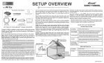
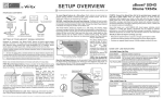
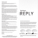
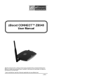
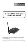
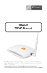
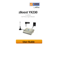
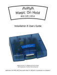
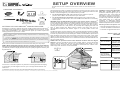
SETUP OVERVIEW zBoost® SOHO YX560Y Download the YX560Y SOHO User Guide at www.Wi-Ex.com PACKAGE CONTENTS strongest signal (up high or outside) and at least 3 feet away from any metal. To get the maximum benefit, you will want to take special care in pointing the antenna in the direction of the best signal for your wireless service provider. SETUP OVERVIEW zBoost Base Unit Power Supply Setup Overview User Guide available at www.Wi-Ex.com Base Unit Antenna To mount antenna to a pole: Attach bracket end of antenna to pole as pictured. Use U-Bolt to secure bracket to pole and fasten. To mount antenna to a flat surface: Attach bracket end of antenna to flat surface using provided screws. Use of the Saddle and U-Bolt are not necessary for this option. SECOND: Place the zBoost Base Unit where you want to create a Cell Zone . Connect the Base Unit Antenna to the Base Unit and place it where you need signal. For the widest possible signal area, position the Base Unit near the middle of a room. You may also mount it on an interior wall by first removing the silver bracket, screwing the bracket to a wall (screws not provided) then snapping the base unit back in place keeping the Base Antenna vertical. This Base Unit uses an omni-directional antenna that delivers signal in a circular pattern around the antenna. TM Signal Antenna & Mounting Hardware Coax Cable RG-6, 50 ft SETTING UP YOUR zBOOST® SIGNAL BOOSTER Designed for consumers, zBoost cell phone signal boosters extend a Cell Zone for multiple users and all devices operating on 800MHz frequency bands - except those using Nextel/iDEN or 4G. zBoost boosts signal up to 6500 square feet, making it perfect for your home or office. TM Before installing, please note the following important factors in determining your zBoost performance: • At least 15 vertical feet is needed between the Signal Antenna (receives the outside signal) and the Base Antenna (rebroadcasts the signal indoors). Separation less than 15 vertical feet will result in decreased performance. (see illustration below). • Keep the Signal Antenna at least 3 feet above any metal. Boost voice and data transmission and increase call clarity in 4 easy steps: FIRST: Mount the Signal Antenna. Choose a location for the Signal Antenna using your cell phone to determine the area of strongest signal. The coverage your zBoost provides is largely determined by the quality of signal received by the Signal Antenna. FOURTH: Connect the zBoost Base Unit to the provided power supply and plug into a power outlet. When your zBoost system is in place and fully connected, walk throughout your home or office and verify that you are able to reliably place calls. If the signal strength has improved, your zBoost is working. Remember, coverage varies based on outdoor signal level, building construction, and antenna placement. Coverage in adjoining rooms (next to, above, or below) will be reduced by walls and ceiling/floors. Upon initial power up, a solid GREEN LED should appear indicating normal conditions. If a RED light appears, adjustments may be needed to optimize performance. If you find the increased signal coverage is acceptable, however, no additional adjustments are needed. See LED Indicator section for more information. Should you desire to improve coverage, you may: • Relocate the Signal Antenna in order to capture a better signal–higher is better. • Increase the distance between the Base Unit Antenna and the Signal Antenna. • Purchase an upgrade antenna available at www.Wi-Ex.com. The zBoost system requires at least 15 feet of vertical separation between the Base Unit and the Signal Antenna. Generally, increasing this distance (up to 40 feet) will increase the performance and decreasing the distance will limit zBoost performance. Keep the Base Unit off the floor and at least 3 feet away from other cords, metal objects or other wireless devices such as wireless routers or wireless access points. zBoost performs best when there are no obstructions between the zBoost Base Unit and your mobile device. THIRD: Run the provided coaxial cable between the Base Unit and Signal Antenna. Use the provided 50 feet of RG-6 coaxial cable to connect the Signal Antenna and the Base Unit. Should you need additional cable length, 15 foot extensions (Part #: YX030-15w) are available at www.Wi-Ex.com. Please note: Cable longer than 65 feet is not recommended. Signal Antenna BASE UNIT LED INDICATORS At Initial Power Up Only Solid GREEN Normal condition at power up. Slowly Alternating RED and GREEN zBoost is working, but at reduced performance and coverage due to “non-ideal” setup. Increase the distance between antenna and amplifier to achieve maximum performance and coverage. Fast Flashing RED Indicates insufficient distance between the antenna and the amplifier. The amplifier is operating at significantly reduced coverage. Solid RED System is receiving signals from either the mobile device or the base station transceiver which are too strong for proper operation. Fast Alternating RED and GREEN followed by no light The amplifier is disabled. Cell Tower 15’ of vertical separation After Initial Power Up 15 ft separation Maximum Performance Minimum Performance Choose one of the above options for placement of the Signal Antenna keeping in mind that if your best signal is one bar, your coverage will be limited to one small room. To maximize signal coverage, place the Signal Antenna where you find the *Note: An 8 inch window entry cable may be needed for this option . It is available for purchase at www.Wi-Ex.com (Part #: YX030-08W) Coaxial Cable Base Unit Antenna Power Supply zBoost Base Unit zBo Solid GREEN Normal condition Solid RED System is receiving signals from either the mobile device or the base station transceiver which are too strong for proper operation. Unplug your system and re-orient the Signal Antenna and/or Base Unit to reduce excessive signal. If LED remains RED after reconnecting power, contact customer support at 1-800-871-1612. Frequency System Gain Band Supported Antenna: Signal Antenna: Base Unit Both PCS and CEL Frequencies Network Format Wall Supply Input; Voltage Power Consumption System Certifications Base Unit Size and Weight Operating Conditions (Base & Power) Coverage (open areas) PCS Frequency 1850 - 1990 MHz ALL: A,D,B,E,F & C N/A * 1 dBi Whip CEL Frequency 824 - 894 MHz 67 dB ALL: A,B, A’ & B’ 11 dBi Yagi; F-type male 1 dBi Whip CDMA, GSM, TDMA, AMPS, GPRS, EDGE, EVDO, HSPA, 3G 100-240VAC 50-60 Hz ; 5.0VDC 3W standby; 7W max signal - 2.0A Max L, FCC Parts 15 & 24 (PCS), FCC Parts 15 & 22 (CEL), Industry Canada 5” x 7” x 1.25” – 9 oz. Indoor Use Only, 5° to 40° C (40° to 105° F) up to 6500 sq. ft. * YX560Y is designed to support 800MHz/CEL and thus does not include a 1900MHz/PCS Signal Antenna. To include PCS coverage, the addition of a YX023-PCS Signal Antenna and YX015D Signal Combiner is required. Handles all PCS or CEL protocols and included multiple patented and patent pending technologies to provide low-cost coverage while continually adapting to signal to prevent interference and remain transparent to the wireless network. Provides an indicator if the antennas are positioned improperly, but will NOT suffer damage of interfere with the Carrier Network. FCC Information FCC ID: SO4YX545-PCS-CEL2 Warning: Changes or modifications to this device not expressly approved by Wi-Ex could void the user’s authority to operate the equipment. Note: This equipment has been tested and found to comply with the limits for a Class B digital device, pursuant to Part 15 of the FCC Rules. These limits are designed to provide reasonable protection against harmful interference in a residential installation. This equipment generates, uses, and can radiate radio frequency energy and, if not installed and used in accordance with the instructions, may cause harmful interference to radio communications. However, there is no guarantee that interference will not occur in a particular installation. If the equipment does cause harmful interference to radio or television reception, which can be determined by turning the equipment off and on, the user is encouraged to try to correct the interference by one or more of the following measures: • Reorient or relocate the receiving antenna • Increase the separation between the equipment and receiver • Connect the equipment to an outlet on a circuit different from that to which the receiver is connected • Consult the dealer or an experienced radio/TV technician for help This equipment complies with FCC radiation exposure limits set forth for an uncontrolled environment. This transmitter must not be co-located or operating in conjunction with any other antenna or transmitter. In accordance with FCC requirements of human exposure to radiofrequency fields, the radiating element (antenna) shall be installed such that a minimum separation distance of 20cm (8in) is maintained from all persons. Industry Canada Regulations Canada IC: 5544A-YX545PCSCL2 This Class B digital apparatus meets all requirements of the Canadian Interference Causing Equipment Regulations. Operation is subject to the following two conditions: (1) this device may not cause harmful interference, and (2) this device must accept any interference received, including interference that may cause undesired operation. The term “IC:” before the radio certification number only signifies that Industry Canada technical specifications were met. RF Exposure: The manufacturer’s rated output power of this equipment is for single carrier operation. For situations when multiple carrier signals are present, the rating would have to be reduced by 3.5 dB, especially where the output is re-radiated and can cause interference to adjacent band users. This power reduction is to be by means of input power or gain reduction and not by an attenuator at the output of the device. Please note: This unit has been approved for use in Canada under RSS 131, however, consent for the use of this device to improve cellular or PCS coverage, must be obtained through your cellular or PCS provider, prior to placing the unit in operation. Please refer to the Industry Canada document CPC 2-1-05, Section 6.1 available or viewable at: http://www.ic.gc.ca/epic/site/smt-gst.nsf/en/sf08942e.html Cet appareillage numérique de la classe [B] répond à toutes les exigences de l’interférence canadienne causant des règlements d’équipement. L’opération est sujette aux deux conditions suivantes: (1) ce dispositif peut ne pas causer l’interférence nocive, et (2) ce dispositif doit accepter n’importe quelle interférence reçue, y compris l’interférence qui peut causer l’opération peu désirée. Le fabricant nominale de la puissance de sortie de ce matériel est simple transporteur. Pour les situations lorsque plusieurs signaux porteurs sont présents, l’évaluation devrait être réduite de 3.5 dB, en particulier lorsque le signal de sortie est ré-émise et peut provoquer des interférences adjacentes à la bande utilisateurs. Ce pouvoir est de la réduction par le biais de la sortie d’alimentation ou la réduction de gain et non par un atténuateur à la sortie du dispositif. WARRANTY INFORMATION LIMITED 2 YEAR WARRANTY | REGISTER AT WWW.WI-EX.COM Wi-Ex warrants every Wi-Ex product to be free from defects in material and workmanship under normal use for the warranty periods of 2 years. Who Is Covered? You must have proof of purchase to receive warranty service. A sales receipt or other documentation showing the product purchased and the purchase date is considered proof of purchase. This limited warranty extends only to the original consumer purchaser or any person receiving the product as a gift from the original consumer purchaser and to no other purchaser or transferee. This warranty does NOT extend to commercial users. What is Covered? Warranty coverage begins the day you purchase the product. For two years from the original date, the Wi-Ex Cell Phone Signal Booster will be repaired or replaced with a new, repaired, refurbished or comparable product (whichever is deemed necessary by Wi-Ex) if it becomes defective or inoperative. The exchange will be made without charge to you for parts and labor. You will be responsible for the cost of shipping to the location designated by Wi-Ex. If Wi-Ex cannot reasonably repair or replace the unit then Wi-Ex may, at its sole discretion, refund the price you paid for the product or the price of the unit. All products, including replacement products, are covered only for the original warranty period. When the warranty on the original product expires, the warranty on the replacement product also expires. What is Excluded? Your warranty does NOT cover: • Labor charges for set up of the unit. • Product replacement because of misuse, accident, lightning damage, unauthorized repair or other cause not within the control of Wi-Ex. • Incidental or consequential damages resulting from the product. Some states do not allow the exclusion of incidental or consequential damages, so the above exclusion may not apply to you. • Any modifications or other changes to the product, including but not limited to software or hardware modifications in any way other than as expressly authorized by Wi-Ex will void this limited warranty. • Product that has been modified or adapted to enable it to operate in any country other than the country for which it was designed, manufactured, approved and/or authorized, or repair of products damaged by these modifications. Make sure you keep… Please keep your sales receipt or other document showing proof of purchase. Attach it to this Setup Overview and keep both nearby. Also, keep the original box and packing material in case you need to return your product. Before requesting repair service… Please review the BASE UNIT LED INDICATORS section listed in this overview - This may save you a call. To get warranty service… Warranty service will be provided by Wi-Ex. If you believe you need service for your unit, contact Wi-Ex at 1-800-871-1612 or [email protected]. A representative will go through a diagnostic checklist with you. If it is determined that the product needs to be returned for service or exchanged, you will receive a return merchandise authorization (RMA) number. The representative will give you complete shipping details. Do not return products to Wi-Ex without a Return Authorization Number (RMA). Reminder: Record the model and serial number found on the product below: Model #: Serial #: Purchase Date: CUSTOMER SERVICE The zBoost SOHO YX560Y User Guide and additional product information is available at www.Wi-Ex.com For questions or assistance, contact Wi-Ex customer service at 1-800-871-1612 or email [email protected].