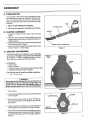
1
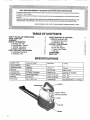
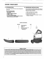
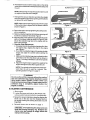
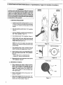
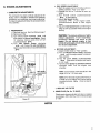
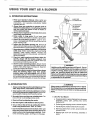
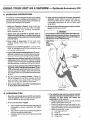
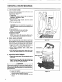
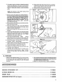
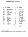
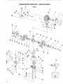
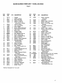
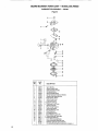
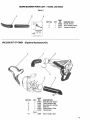
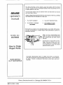
,,,,,
operator's
manual
MODEL NO.
358.796920
I
2 _©6® Eng_n®
Z_WARNING:
Carefully read and follow all
Safety Rules, Precautions
and Operating Instructions.
Failure to do so can result in
serious personal injury,
Sold
by
Sears,
Repair
o Operation
and
, ,,
66517-3-24085-1-24085
e Maintenance
o Assembly
Roebuck
Fu®nU_x t 6:1
C()., Cllicago,
IlL 60684
Parts
U.S.A.
,,,
PRINTEO
IN
U
S
A
TABLE OF C@NTEN3=$
SAFETY RULES AND PRECAUTIONS ..............
KNOW YOUR UNIT ...................................
ASSEMBLY ........................................
ENGINE INFORMATION .............................
A, Fueling Your Unit ............................
B, Pre-Operation Checks ...........................
C Starting Instructions............................
D. Engine Adjustments..........................
USING YOUR UNIT AS A BLOWER ...............
A, Operating Instructions.............................
B_Operating Tips ...........................
3
4
5
7
7
7
8
9
10
10
10
USING YOUR UNIT AS A VACUUM
(Optional Accessory Kit)
A Operating Instructions
B. Operating Tips.
.
.
GENERAL MAINTENANCE
A, Air Filter Care
B Fuel Tank Upkeep
C, Starter Rope Repair
D. Storage.
ACCESSORIES
PARTS LIST
SPECJFI©ATJ@N$
ENGINE TYPE:
2 Cycle Air Cooled
DISPLACEMEN31
28.0 cc
OPERATING RPM:
IGNITION:
MUFFLER:
LoTone
75008200
VELOCITY:
150mph
Solid State
AIR VOLUME
340 cu. ft./min.
CARBURETOR:
All Position - Diaphragm
SPARKPLUG:
CJ-8 (Cat,No, 71-36403)
ON/OFF SWITCH:
Positive Toggle Switch
SPARKPLUGGAP:
.024"- .027"
STARTER:
Auto Rewind
MODULE AIR GAP:
.010"- .014"
FUELTANK:
400cc (13.5 fl, oz.)
LUBRICATION:
Gasoline/oil Mixtu're_ see Page7
STARTER ROPE
/HANDLE
;WITCH
2
11
11
12
12
12
12
13
13
14
Failure to follow all Safety Rules and Precautions could result in serious personal injury.
A. KNOW YOUR
1 Read your Operator's Manual carefully until you
completely understand and can follow all safety
rules, precautions, and operating instructions
before operating the unit.
2, Restrict your unit to users who understand and
follow all safety rules, precautions, and operating
instructions found in this manual,
PLAN AHEAD
1 Always wear eye protection to prevent recks or
debris from being blown or ricocheting into eyes
and face which can result in loss of vision or
serious personal injury.
2, Always wear a respirator or facemask when
working with the blower in dusty environments.
3, Dress safely in long pants. Do not wear loose
clothing, jewelry, short pants or sandals; or go barefoot
4 Do not operate the unit when you are tired, ill, or
upset; or if you are underthe influence of alcohol,
drugs, or medication.
5 Keepchlldren, bystandersandanimalsawayfrem
the work area, a minimum of 3O feet (lO meters),
when starting or operating the unit.
6 Inspectthearaabeforestartingtheunit.
Removeall
debris and hard or sharp objects such as rocks, glass,
wire, etc that can be blown or cause damage during
operation. As a vacuum, the unit is designed to pick up
dry material such as leaves, grass, small twigs and bits
of paper. Do not vacuum stones, gravel, metal, broken
giass etc. to avoid severe damage to the impelle_ Do
not attempt to vacuum water or other liquids to
avoid damage to the engine.
C, NANDILI
IFU ' = WSTH CAUTaON
1 Eliminate all sources of sparks or flame (including
smoking, open flames, or workthat can cause sparks)
in the areas where fuel is mixed, poured, or stored
2, Mix and pour fuel in an outdoor area; store fuel in
a cool, dry, wen,ventilatedplace;
and use an
approved, marked container for all fuel purposes.
3. Do not smoke while handling fuel or while
operating the unit.
4 Do not fill the fuel tank while the engine is running
or strapped to the operator.
5 Wipe up all spills before starting the engine.
6_ Move at least 10 feet (3 meters) away from fuel and
fueling site before starting the engine_
D, OPERATE
_'OUR UNgT SAFI_LY
1 Stoptheenginebeforeopeningthevacuuminlet
door or attempting to insert or remove the suction
tube. The engine must be stopped and the impeller
blades no longer turning to avoid contact with the
rotating blades
2_ Inspect the entire unit before each use for worn,
loose, or damaged parts. Do not use until the unit is
in proper working order.
3 Keep the outside surfaces free of oil and fuel.
4 Never start or run the engine inside a closed room
or building. Exhaust fumes contain dangerous carbon
monoxide
5 Do not wear rubber or any other insulated gloves
when using the unit as a vacuum to avoid static
electricity shock.
6 Donotsettheunitonthegreundtostarttheengine
or while the engine is running. Debris such as gravel,
sand, dust, grass, etc could be picked up by the air
intake and thrown out through the discharge opening,
damaging the unit, property or causing serious
personal injury to bystanders or the operator
7 Avoid dangerous environments.
Do not use in
unventilated areas or where explosive vapors or carbon
monoxide build up could be present
8 Do not overreach or use from unstable surfaces such
as ladders, trees, steep slopes, rooftops, etc Keep firm
footing and balance at all times
9 Never place objects inside t he blower tubes; always
direct the blowing debris away from people,
animals, glass, and solid objects such as trees,
automobiles, walls, etc The force of air can cause rocks,
dirt, or sticks.to be thrown or to ricochet which can hurt
people or animals, break glass or cause other damage
10 Neverplaceanyobjectintheairlntakeopeningas
this could restrict proper air flow and cause damage to
the unit
11 Never run the unit without the proper equipment
attached. When used as a blower, always install a
blower tube When used as a vacuum, always install the
suction tube and collection bag Make sure the
collection bag assembly iscompletely zipped when the
unit isrunning to avoid flying debris
12 Always use the shoulder strap attached to the
collection bag when vacuuming to avoid loss of
controJ
13 Never use for spreading or misting chemicals, fertilizera or toxic substances.
14 Avoid situations that could catch the collection
bag on fire. Do not operate near an open flame Do
not vacuum warm ash from fireplaces, barbecue pits,
brush piles, etc_ Do not vacuum discarded cigars or
cigarettes unless cinders are completely cool
15,
Use only for jobs explained in this manual.
E. MA"NTADN YOUR UNliT PROPERLY
1oMaintain the unit according to recommended
procedures.
2, Disconnect
spark plug before performing
maintenance except for carburetor adjustmenL
3 Use only genuine replacement parts as recommended by Sears to avoid creating a hazard and/or
voiding your warranty.
4 Check air intake openings and blower tubes frequently, always with the engine stopped. Keep
vents and tubes free of debris which can accumulate
and restrict proper air flow
5 Never make engine adjustments
with the unit
strapped to the operator.
6. Drain fuel frem the fuel tank before storing for 30 or
more days.
7 Do not use any accessory or attachment other
than those supplied by Sears for use with this particular uniL
8 Do not store the unit or fuel in a closed area where
fuel vapors can reach sparks or an open flame from
hot water heaters, furnaces, etc.
9 Store in a dry area out of the reach of children.
3
NOW
YOUR UNIT
A, _NTRODUCT_ON
B. UNPACKONG
Your unit is a high performance product designed for
tough jobs.
Special Features Include:
= One-handed Operation
o Direct Drive
o Vibration Dampened Handle
° Weight- 1151bs.
= Convenient Upright Storage
Easy Conversion to Vacuum Capability with the
Optional Accessory Kit #71-79991.
mNSTRUCTqONS
Your unit has been carefully packed at the factory to
prevent damage during shipping and storage, Carefully
unpack the carton as follows:
1 Remove corrtents from the carton_
2. Check parts against the list below
3. Examine parts for damage
4 Notify your Sears Store immediate/y if a part is
missing or damaged,
CARTON CONTENTS:
KEY NO.
1
2
3
4
--
Engine Assembly
Blower Tube
Nozzle
8 oz.,2-cycle Engine Oil
Operator's Manual (Not Shown)
QTY.
1
1
1
1
1
4
f_l
1
3
/
SPECIAL NOTICE
For users on U.S. Forest Land and in the states of California, Maine, Oregon and Washington. All US ForestLand and
the statesof CaUfornia(Public Resources Codes 4442 and 4443), Oregon and Washington require, by law,that certain internal cornbustion engines operated on forest, brush and/or grass-coveredareas be equipped with a spar k arrestor, maintained
in effectiveworkingorder,or the engine be constructed,equipped and maintained for the prevention offire. Check with your
state or local authoritiesfor regulationspertaining tothese requirements. Failureto follow these requirements could subject
you to liability or toa fine. This unit is not factory-equipped with a spark arrestor. Ifthese items are required in yourarea,
ask your dealer to install Part# 69207.
Your Operator's Manual has been developed to help
you assemble the unit and to understand its safe operation It is important that you read your manual completely to become familiar with the unit before you begin
assembly,
1. READ YOUR OPERATOR'S
KNOB
MANUAL,
BLOWER TUBE
2_ No tools are required to assemble your blower,
B.
BLOWER
ASSEMBLY
NOZZLE
\
1 Thread the nozzle onto the blower tube and firmly
tighten,
2 Slide the blower tube and nozzle assembly into the
engine housing until it bottoms out (approximately 2-t/2
inches) Figure 1_
3, Align the blower assembly sothat it is pointing up toward
the handle as shown in Figure 1.
4, Secure the blower assembly by tightening the knob
shown in Figure 1 until hand-tight
Co VACUU_
NORMALANGLEOFDISCHARGE
Figure
1
COHVERSION
Your blower engine can be adapted to vacuum capability
with the properinstallation of the optional Vac Attachment
Kit, Stock No_71-79991. available through your Sears
Store, Follow the assembly instructions below:
BOTTOM
VIEW
THUMB
_NUT
o Kit Contents:
-- Suction Tube
-- Clamp w/Screw
-- 2 Bushel. Heavy Duty Collection Bag w/Shoulder Strap
--Adjustable Shoulder Strap (for engine)
o The only tool you will need is a slotted screwdriver.
VACUUM
INLET DOOR
_WARNING
Stop engine before opening the vacuum inlet door or
attempting to insert or remove the suction tube. The
engine must be stopped and the impeller blades no
longer turning to avoid contact with the rotating blades.
Figure 2
1 Stop Engine
2 Loosen the knob (Figure 1)and remove the blower tube
from the engine
CLAMPING RING_
3 Set the unit on a flat surface as shown in Figure 2,
and unthread the thumb nut holding the vacuum inlet
door closed
//
IMPELLER
4 Using a screwdriver, unthread the screw holding the
clamp together and separate the ends of the clamp,
5 Hold open the vacuum inlet door and slide one end of
the open clamp under the vacuum inlet door hinge and
around the clamping ring on the housing as shown in
Figure 3.
VACUUM
Figure 3
6, Reinstall the loose end of the clamp and turn the clamp
screw with a screwdriver to loosely secure the clamp onto
the unit
NOTE: Observe that one end of the suction tube is cut at
an angle and the other end is straight,
/
7, Hold open the vacuum inlet door and slide the straight
end of the suction tube into the opening until it bottoms
out (about 3/4 inch). Figure 4,
NOTE: Make sure the warning decal and shorter angle
of the suction tube is aligned with the blower' outlet as
shown in Figure 4.
WARNING DECAL
VACUUM INLET DOOR
Figure 4
KNOB
8. Secure the suction tube bytightening the clamp screw
with a screwdriver,
9. Slide the collection bagtube into the blower opening until
it bottoms out (about 2-1/2 inches). Figure 5,
10, Align the notch on the collection bag tube with the center
seam of the blower outlet as shown in Figure 5, then
secure the collection bag tube to the engine with the
knob until tland-tighL
11 Shoulder Strap Adjustments
a It iseasier toput on the collectionbag strap first, then
the engine strap, clipping the strap to the engine
last Figure 6_
b Tryon both the collection bag and the engine shoulder
straps and adjust for comfort before starting the
engine
c. Make sure the collection bag strap is adjusted to allow
a free flow of air from the elbow tube as shown in
Figure 7. If the bag is kinked,the unit will not operate
properly.
d Adjust the engine strap to support the weight of the
engine leaving the hands free to guide the unit,
Figure 5
RING
NOTE: The controls on the engine are directed forward when the unit is used as a vacuum See
operating position in Figure 14, page 11
Figure 6
Z_WARNING
Do not use the unit as a vacuum without the suction
tube and collection bag properly attached to avoid
flying debris and/or impeller contact which can
cause serious personal injury. Always make sure the
collection bag is completely zipped before the
engine is started.
Do B -OWER
CONVERSaON
! Stop engine,
2 loosen the screw and knob on the clamps, ther]
remove suctiontube and collection bag assembly.
3 Secure the vacuum inletdoor closed by aligning the
thumb nut on the door over the threaded stud on
the engine housing and turning tile thumb nut until
fingePtighL
BAG KINKED
4 Reinstall blower tube as shown on page 5
[ CAUTION: ! Over tightening the clamp screw can
break the housing clamping ring. Retighten the
clamp screw just enough to snugly secure the
clamp on the housing.
WRONG WA'_/
WAY
Figure
7
EN@ NE INF@RMATMON
A= FU_L,gNG
YOUR
UNI;T (See "Specifications,
4. DO NOT USE:
1. FUEL MIXTURE
o Your unit is powered by a 2-cycle engine which
requires a fuel mixture of regular, unleaded
gasoline and a high quality engine oil specially
made for 2-cycle, air-cooled engines, The internal design of the 2-cycle engine requireslubrication
of moving parts Lubrication is provided when you
use the recommended mixtureof gasolineand oil.
• Gasoline must be clean and not over two
months old. After a short period of time, gasoline
begins to chemically break down and willform compounds that can cause hard starting and damage in
2-cycle engines
o The correct measure of gasolinetoeilisveryimportant. Too much oil will foul the spark plug. Toolittle oil will cause the engine tooverheat and freeze up
• Always mix the fuel thoroughly in a container
since gasoline and oil do not readily combine. Do not
try to mix fuel directly in the fuel tank
2_
page 2, for location of Fuel Cap.)
USE THE FOLLOWING:
° BIA OIL (Boating Institute of America) --- Does not have proper additives for air-cooled,
2_cycle engines and could cause damage
o AUTOMOTIVE OIL ---Does not have proper additives for 2-cycle
engines and could cause damage
• GASOLINE CONTAINING ALCOHOL
(High Test, Premium or Gasohol) ---Stiffens
critical carburetor fuel metering
eler_ents and causes engine damage from
overheating
--Increases vapor lock (causes hard starting)
-- Attracts water causing corrosion damage
5. IMPORTANT POINTS TO REMEMBER
a, Use only recommended
1 GALLON
REGULAR
UNLF_DED
_-
-- OR--
_
fuel mixtures.
b Eliminate all sources of sparks or flame in the
areas where fuel is mixed, poured, or stored.
There should be no smoking, open flames or
work that can cause sparks.
c Use an approved, marked container for all fuel
purposes.
3. HOW TO MIX FUEL
a Pour one-half of the gasoline into an approved
marked container. Do not try to mix fuel directly
in the h_el tank.
b Add entire measure of 2-cycle Engine OiL
c. Mix.
d. Add remainder of gasoline.
e Mix thoroughly for one mim,te.
B, PRE-OPERATBON
CHECKS
Before operating your unit, always:
t. _- CHECK OVER SAFETY RULES AND PRECAUTIONS in this Operator's Manual Make certain you
completely understand and follow each one
2. ,-- CHECK THE AIR FILTER.
Clean the filter before operating the unit, See Figure 15.
d Mix and pour fuel in an outdoor area. Store fuel
in a cool, dry, well-ventilated place. Gasoline
vapors are harmful to your health and can cause
serious hazards,such as explosion and fire Use a
funnel or spout when pouring fuel
e. Wipe up all fuel spills before starting the
engine.
f. Move at least 10 feet (3 meters) away from fuel
and fueling site before starting the engine.
3. v" CHECK THE UNIT FOR lOOSE BOLTS, NUTS,
OR FITTINGS.
Tighten, repair or replace parts as necessary. Use
only genuine replacement parts;
4. v" CHECK THE FUEL TANK.
Fill with a clean, fresh fuel mixture according to
instructions in fuel mixture section
,,,,,,
i,
A= STARTING mN$3"RUCI"I]ON$ (Refer to "Specifications,"
z_WARNING
Hold the unit for starting as shown in Figure 8. Do not set
the unit on the ground to start the engine or while the
engine is running. Debris such as gravel, sand, dust,
grass, etc. could be picked up by the air intake and
thrown out through the discharge opening, damaging
the unit or property or causing serious personal injury
to bystanders or the operator.
1 STARTING
page 2, for location of controls.)
BLOWER
STARTING
VACUUM
STARTING
PROCEDURE
Hold the unit in the starting position as shown
in Figure 8 Make sure the end of the unit isdirected away from people, animals, glass and solid
objects
b
Move the ignition switch to the "On" position.
Figure 9
c
Turn the throttle control knob clockwise to
the "Fast" position. Figure 10_
d
Turn choke knob to "On" position. Figure 11
e_
Hold handle with your right hand and pull
starter handle with your left hand until the
engine fires (attempts to run)
NOTE: Do not let the starter rope snap back
between pulls_Hold the handle and let the rope
rewind slowly
f
Figure 8
IGNITION SWITCH
THROTTLE CONTROL
Turn choke knob to "Half" position and pull
starter handle until engine runs. Figure 11.
ON
Allow engine to warm-up as indicated below,
then turn choke knob to the "Off" position.
Figure 11
-- Above 40°1:,warm-up 10o20seconds
-- Below 40°F, warm-up 45.60 seconds
/
OFF ,
Figure 9
h.
Figure 10
Stop engine by moving ignition switch to the
"Off" position. Figure 9
CHOKE KNOB
2. IMPORTANT
When starting the engine, always pull the
starter rope sharply and quickly, but not
more than 10 times to avoid flooding the
engine. If flooding occurs, turn choke to the
"Off" position (Figure 11) and pull starter rope
until engine starts
a
b_
C
8
POINTS
Start a cold engine with the choke at the "On"
position Figure 11
Start a warm engine with the choke at the "Off"
position If unit fails to start witilin 2 pulls, move
choke to the "Half" positiorLFigure 11
OFF
Figure 11
D= ENGBN
ADJUSTMSNTS
1. CARBURETOR
ADJUSTMENTS
The carburetor has been carefully adjusted at the
factory. Due to changes in altitude and operating
conditions, your carburetor may require adjusting.
To make the adjustment follow the procedure below
very carefully:
a PREPARATION
1) Use fresh fuel mix See Fuel Mixture page 7
2) Remove air filter
3) Turn mixture screw clockwise
_
until
fully closed, but do not overtighteno Figure
12 Unscrew mixture screw one full turn
counterclockwise
4) Turn
Idle
Speed
Screw
clockwise
==,=-_ until it stops Do not overtighten.
Open screw three full turns counterclockwise
/
IDLE SPEED
ADJUSTMEN1
b IDLE SPEED ADJUSTMENT
1) Start the engine and turn throttle control to
halfway between "Fast" and "Slow"
2 ) Operate the unit for 3 minutes to warm up
engine
3) Turn throttle
control
counterclockwise
to slow setting
4) Adjust Idle Speed Screw:
Clockwise
_
if the engine stalls:
Counterclockwise
_
to slow engine
down
5 ) Adjust the Idle Speed Screw until the engine
idles as slow as possible without the engine
stalling
t CAUTION:] The mixture setting is a highly
critical adjustment.
If set incorrectly,
permanent
damage will occur to the
engine. Do not operate engine at fast
throttle fdr prolonged periods while making
the mixture adjustment.
c MIXTURE ADJUSTMENT:
1) Adjust throttle knob to "Fast" position
2 ) Turn the Mixture Screw slowly clockwise
until the engine speed is reduced
Note position
3) Turn the screw slowly
counterclockwise
_===_ Stop when the engine just begins
to run rough
4) Turn the screw slowly the minimum amount
clockwise
==="_ until the engine runs
smoothly
NOTE 1: The mixture screw should be in the
range of 3/4 to 1-1/4 turns open
NOTE 2: For the best engine performance, it
is better to run a slightly rich mixture setting
(counterclockwise
_
)than too lean a
setting
d REPLACE AIR FILTER
2. SPARK PLUG (Cat. No. 71-36403)
Check spark plug periodically and clean or replace
as necessary. After cleaning, reset the electrode gap
to "025,
-i
Figure 12
N ES
9
USING YOUR @N T AS
A. OFE T NG
L@WER
HSTRUCTaON$
ALWAYS USE
1 Read your Operator's Manual, Make certain you
completely understand and can follow all safety rules,
precautions, and operating instructions, before
operating the uniL
2 Always wear eye protection to prevent rocks or
debris from being blown or ricocheting into eyes
and face which can result in loss of vision or
serious personal injury.
3 Always wear a respirator or facemask when workmg in dusty environments.
4 Dress safely in long pants. Do not wear loose
clothing, jewelry, short pants or sandals; or go barefoot
5 Check the unit before operation. Look for worn,
loose, or damaged parts Do not use until the unit is in
proper working order
6 Inspect the area before starting unit. Remove all
debris and hard objects such as rocks, glass, wire, etc
that can be blown or cause damage during operation
7 Keepobservers, children, bystanders, andanimals
safely away. Before starting the engine and during
_Pseration, make certain children, animals and
tanders are away from the work area - a minimum of
30 feet (10 meters).
8 Check air intake opening and blower tubes frequently, always with the engine stopped. Keep
vents and discharge tubes free of debris which can
accumulate and restrict proper air flow
9 Use the correct operating position. (Figure 13.)Do
not overreach or use from unstable surfaces such as
ladders, trees, steep slopes, roof tops, etc_ Keep firm
footing and balance at all times
1Q Never place objects inside the blower tubes; always
direct the blowing debris away from people,
animals, glass, and solid objects such as trees.
automobiles, walls,etc The force ofair can causerocks.
dirt, or sticks tobe thrown or to ricochetwhich may hurt
people or anirnals, break glass, or cause other damage
B. OPI RATBNG TIPS
Always work going away from solid objects such as
walls, large stones, automobiles and fences,
2 Clean spaces with corners by starting in corners
and moving outward to straight areas toprevent an
accumulation of debris which could fly into face
,
Be careful when working near valuable plants. The
force of the air could damage tender plants
4 Direct air flow by adjusting the nozzle.
Run the engine at full throttle for full air power=
6 Vary or reduce the air flow by setting the throttle
knob at any position from "Fast" to "Siowo"
7 Use the handle located on the bottom of the unit
5,
below the control panel when working above the
waistorwhenatwo-handedgripisdesired.
Refer
tothe unit drawing, page 2, and Figure 13,this page
10
"_EYE
PROTECTION
USE RESPIRATOR
OR FACEMASK
FOR DUSTY
ENVIRONMENTS
OPERATION
WITHBOTH
HANDLES
HANDLE
CONTROL
PANEL
TO THE _`_
REAR
HANDLE
Figure 13
z_WARNING
Hold the unit for starting as shown in Figure 8. Do not
set the unit ontheground tostart theengineorwhilethe
engine is running. Debris such as gravel, sand, dust,
grass, etc. could be picked up by the air intake and
thrown out through the discharge opening, damaging
the unit or property or causing serious personal injury
to bystanders or the operator.
z_WARNING
Always wear eye protection to prevent rocks or debris
frern being blown or ricocheting into the eyes and face
which can result in loss of vision or serious personal
injury.
8 -Uses For Your Blower:
a Sweeping debris or grass clippings from driveways,
sidewalks, patios, park, parking lots, barns,
stadiums, etc
b Gathering grass clippings, straw or leaves intopiles
c Fast drying wet, outdoor areas such as a patio
d Removing debris from corners, around joints and
between bricks
e Blowing light snow from driveways, sidewalks or
patios
As a vacuum, the unit is designed to pick up dry material
such as leaves, grass, small twigs and bits of paper. Do not
attempt to vacuum stones, gravel, metal, broken glass, etc.
to avoid severe damage to the impeller.
1 Read your Operator's Manual, Make certain you
completely understand and can follow all safety
rules, precautions, and operating instructions,
before operating the unit
2 Always wear eye protection to prevent rocks or
debris from being blown or ricochet;_g into eyes
and face which can result in loss of vision or serious
personal injury.
3 Dress safely in long pants. Do not wear loose
clothing, jewelry, short pants or sandals; or go
barefoot
10 Never run the unit without the proper equipment
attached. Always install the suction tube and collection bag. Make surethe collection bag assembly
is completely zipped when the unit is in use to avoid
flying debris
11 Always use the collection bag and engine shoulder
straps to avoid loss of control.
Z_WARNING
Do not insert or remove suction tube with engine running to avoid serious personal injury. Always stop the
engine before unclogging the unit or performing any
maintenance on the collection bag.
COLLECTION
BAG
STRAP
4 Check the unit before operation, Look for worn,
loose, or damaged parts Do not use until the unit
is in proper working order
5 Inspect the area before starting the unit. Remove
all debris and objectssuch as rocks,glass,wire, large
sticks, etc that can cause damage during operation
ENGINE
STRAP
6 Keepobservers, children, bystanders, andanimals
safely away. Before starting the engine and during
operation make certain people and animals are away
from the work area - a minimum of 30 feet (10 meters).
7 Check air intake opening and collection bag tube
frequently, always with the engine stopped. Engine
RPM will increase significantly when the suction or
collection bag tube is clogged. Keep vents and tubes
free of debris which can accumulate and restrict proper
air flow.
CONTROL
"/PANEL
8 Use the correct operating position. (Figure 14)
Do not overreach or use from unstable surfaces
such as ladders, trees, steep slopes, roof tops, etc
Keep firm footing and balance at all times
9 Do not wear rubber or any other insulated gloves
to avoid static electricity shock.
Figure 14
B. OP_RATnNG
T_PS
1, Move the unit slowly back and forth over debris
to be vacuumed, Avoid forcing the suction tube into
a pile of debris as this can clog the unit.
2 If the unit becomes
a.
b
c
clogged:
Stoptheengineanddisconnectthesparkplug.Do
not attempt to remove obstructions with engine
running.
Wait until the impetler has completely stopped turning, then remove the suction tube
Carefully reach into the vacuum opening and clear
out debris
3 The collection bag must be properly emptied
,and maintained to avoid deterioration a nd obstructing air flow which will reduce the
performance of the vacuum.
a. Empty the bag after each use. Do not store bag
containing wet grass, leaves, etc
b. Clean the bag after every three uses by turning the bag inside out after initial emptying and
vigorously shaking out dust and excess debris
c. Wash the bag once a year
1) Turn bag inside out
2). Hang up
3). Hose down thoroughly
4). Hang to dry
11
MA NTENAN©E
Ao AIR
FILTER
CARE
A dirty air filter decreases engine performance and
increases fuel consumption_
Clean the Air Filter:
• Frequently,
o Always clean after 5 tanks of fuel or 5 hours of
operation, whichever is less.
Follow these steps:
1 Remove the air filter (located above the control
panel; see Figure 15)
2 Wash in soap and water
I CAUTION:I Do not clean filter in gasoline or
other flammable solvent to avoid creating a fire
hazard.
& Squeeze filter dry
4 Add a small amount of oil to coat the filter,
NOTE: Avoid soaking the filter with oil
5 Squeeze out excess oil
6 Replace the air filter.
NOTE: Make sure the filter is properly fitted into the
housing, paying particular attention to the corners.
Bo FUEL TANK UPKEEP
Never use gasoline that is more than 2 months old
in a fuel mixture. Gasoline begins to break down after
a short period of time and will form compounds that
cause hard starting and damage in 2-cycle engines
Figure 15
1 Inspect the unit for fuel leaks each time it is
used. Repair or replace parts as necessary
2 Always begin operation with a clean, fresh
mixture of fuel.
3 Drain all fuel from the unit or allow unit to run
out of fuel before storing for 30 or more days.
C. STARTER
FAN HOUSING
REMOVE
SCREWS
ROPE REPAIIR
• Repair the starter rope if the rope breaks next to
the pulley.
--_.
F
SPARK PLUG WIRE
o Replace the starter rope if the rope breaks more
than 2-3 inches away from the pulley as the rope
will be too short to repair properly.
Z_WARNING
Always wear eye protection when servicing the starter
rope. The recoil spring, located beneath the pulley, is
under tension. If the spring pops out, serious personal
injury can result.
° To repair or replace:
1 Disconnect the spark plug wire and remove the 6
screws from the fan housing. Figure 16,
2 Separate the far] housing completely from the
shroud
12
Figure 16
If the starter rope is not broken, release the spring's
tension by pulling about 10 inches of rope from the
pulley and catching the rope in the notch as shown
Figure 17 If the rope is broken, remove the broken
piece.
3
I5. Align pulley notch with rope exit hole, pull starter
handle to the full extent of the rope and allow the
rope to slowly wind around the pulley
16 Reinstall the fan housing to the shroud.
NOTE: The tension on the starter spring will be
released ifthe rope is broken
4_ Remove screw and pulley very carefully, Figure 17
The recoil spring which lies beneath the pulley
must stay in the housing, flat against the bottom. If the spring is disturbed, it will require considerable time and effort to reinstall. Twist the
pulleygentlycounterclockwise
_
asyoupull
up to release the spring
5 Move away from the fueltank and melttheend ofthe
rope to go into the pulley`
6 Allow the melted end to drip once; then while the
rope is still hot, pull the melted end through a rag to
obtain a smooth, pointed end
7 Insert rope through the rope exit hole in the fan
housing
8 Snake rope inside the pulley, then through topside
pulley hole by pushing the rope from the underside
holewith a small round object such as a Phillips
screwdriver. See Insert, Figure 18
9 Wrap rope counterclockwise
_
around
pulley ratchet and tuck loose end back under rope
leaving a 3/8 to 1/4 inch tail Figure 18 Pull tightly
l& Wind all but about 10 inches of the rope counter
clockwise _
around pulley
11_ Replace pulley in the housing Be sure the pulley is
all the way down and the spring is secured
12. Replace and tighten pulley screw Figure 17.
13 Hold the 10 inch slack in the rope and catch rope
in pulley notch. Figure 19
14 Hold the rope taut and make 2 complete turns
of the pulley counterclockwise
_
to place
tension on the pulley Hold the pulley to retain
tension
;HET
Figure 17
SCREWDRIVER
._"
/
/
/
__
Figure 18
\
NOTCH
Figure 19
D, STORAGE
1 Clean the unit before storing. Pay particular attention to the air intake area,keeping itfreeof debris Use
a mild detergent and sponge to clean the plastic
surfaces
2 Do not store the unit or fuel in a closed area where
fuel vapors can reach sparks or an open flame from
hot water heaters, furnaces, etc.
3. Store in a dry area out of reach of childrenr
A©©A$$@RBA$
VACUUM
ATTACHMENT
2-CYCLE
ENG_IRE OHL .......................
SPARK
PLUG
SHOULDER
K_T ..................
mmwwmwmlmmwm=_lm
====B=l=mm.mm#_
...........................
STRAP
I_BT (for Engine)
............
mmmm_m=#==m=_#=
............
71-79991
.......
7%36555
illll .......
............
7t-85783
13
SEARS
BLOWER
PARTS
UST
_
MODEL
358.796920
Figure 1
102
25
2
.j
15 16
/
19
101
2O
14
13
11
10
31
32
33
34
35
33
o
38
43
42
41 40
38
14
SEARS
BLOWI=R
PARTS
LOST -- MODEL 358.796920
Figure 1
KEY
NOo
PART
NO.
CITY, DESCRIPTION
1
2
10828
15635
1
2
5
6
7
8
g
24256
15343
26163
15629
15628
3
1
6
2
2
10
11
15561
15342
2
2
12
13
32091 *
15678
1
2
14
15
16
17
18
19
20
21
22
23
24371
15676
15677
10821
42023
26780
28626
15479
15123
15544
1
4
4
1
1
1
1
1
1
4
24
25
27
28
29
30
22289
26735
15664
94222
94242
15636
1
1
1
1
!
3
Ass'y - Handle(Incl #2)
Screw - 10 - 14 x 11116Bind, HdHandle
Isolator - Handle
Spacer - Isolator (Front)
Cup - Isolator
Washer #8 - Front
Screw - 8 - 32 x 7/16 Rind Hd Fan Hsg/Crankcase
Screw- 12- 11 x 2
Spacer - Isolator (Rear)
KEY
NO.
PART
NO,
QTY,
31
32
33
34
35
26776
10824"
10835
94215
15661
1
1
1
1
1
37
38
15064
15367
1
10
39
40
41
42
15644
15441
15626
15632
1
!
1
4
15682
4
15168
4
1516
15667
15647
15672
94241
15638
!5637
26781
91678
21058
10729
10615
1
1
!
1
1
1
1
1
1
1
1
1
26778
26777
1
2
26925
1
Bearing-Ball (Shroud)
Screw - 10 +24 x 5/8 Bind Hd +
Fan Hsg/Crankcase
43
Air Filter
Screw- 10 - 24 x 7/8 - Fan Housing 44
Washer - Fan Hsg
Fan Housing
45
Spring - Starter Pulley
46
Baffle - Air
47
Pulley Starter
48
Screw +10 - 3/4 Hex Hd +Pulley
49
Washer - Starter Pulley
50
Screw - 10 x 3/8 Pan Hd 51
Air Baffle
52
Rope (3 ft )
53
Handle - Starter Rope
54
Bolt - 1/4 - 20 x 1-1/2- Clamp
56
Clamp - Blower Tube
57
Knob - Clamp
Screw -10 - Heat Deflector
DECALS
101
102
103
DESCRIPTION
Deflector- Heat
Shroud - (Incl # 12 & 45)
Ass'y- Blower Hsg (IncL 9 of#38)
Impeller
Screw - 10 - 14 x 88 Blower Hsg/Inlet Door
Nut - 10- 24
Screw - 10 - ! 4 x 3/4
Pivot Pin/Blower Hsg
Nut - Impeller
Washer +Conical - Impeller
Washer- Flat- Impeller
Screw - 1/4- 20 x 7/8 +
Blower Hsg/Shroud
Washer - Blower Hsg/Shroud
Screw- 10 +24 x 5/8Shroud/Crankcase
Retainer-Bearing-Shroud
Spring - Tension (Right)
Pin - Pivot
Spring - Tension (Left)
Ass'y - Inlet Door
Screw - 1/4 x 20 1/2 - Retainer
Retainer +Fuel Tank
Cushion - Fuel Tank
Ass'y - Fuel Pick-up
Line - Fuel - Tank
Ass'y - Fuel Cap w/Retainer
Ass'y - Fuel Tank
(Incl #53, 54 & 56)
Decat- Instruction
Decal - (Left & Right) Fan
Housing
Deca_- Warning-Blower Hsg
Key Nos+Excluded: #3, 4, 26, 36 & 55
*When removing or installing the bearing (#32091), the area of the shroud (#10824) receiving the bearing must be heated to
approximately 3000E to avoid damaging the shroud
15
SEARS
BLOWER
PA_$
L_S_ =-- MODEL 358.796920
5
Figure 2
7
8
14
15
o/
18
19
21
/
29
28
22
22
13
12
21
11
26
12
72
52
53
3
/
56
55
SPARK
ARRESTOR
KIT
16
SITARS
BLOWER
PARTS
LIST
--
MODEL
358.796920
Figure 2
KEY
NO.
PART
NO.
1
2
3
4
5
12112
19111
26681
15162
15239
1
1
2
2
2
6
7
8
9
10
11
12
13
14
15
18
19
20
21
22
26949
10809
24361
24903
69203
94219
94218
94243
626605
23817
26765
32057
15351
32058
1O819
1
1
1
2
1
1
2
1
1
2
1
1
2
2
1
23
26
27
28
19059
15377
15126
15168
2
1
1
4
29
30
31
32
39111
15127
24438
19108
1
1
1
1
33
34
191O5
15241
1
1
35
36
37
38
39
40
41
23367
26818
19115
25472
21056
26797
26772
1
1
1
1
1
1
1
QTY, DESCRIPTION
Cylinder
Gasket- Cylinder
Ring - Piston 28cc
Retainer - Wrist Pin
Screw - 1/4- 20 x 3/4 Hex Soc Hd.* Cylinder
Diffuser - Muffler
Ass'y - Body-Muffler
Cover - Muffler
Spring - Muffler Attachment
Piston Kit (IncL#3, 4 & Pin)
Shaft - Arbor
Coupling - Shaft
Coupling - Plastic
Nut - Flywheel - 5/16 x 24
Spring - Starter Dog
Ass'y-Crankshaft&Rod
Bearing - Wrist Pin
Washer-Thrust-Crankcase
Bearing - Crankshaft
Crankcase Ass'y.
(Incl. #21 & 23)
Seal - Crankcase
Washer - Coupling
Key - Flywheel
Screw - 10 - 24 x 5/8 Fil. Hd.
Crankcase
Flywheel Assembly (Incl. #15)
Washer* Flywheel
Reed Valve
Gasket - Carburetor Case to
Crankcase
Seal - Carburetor Case
Screw- 6 - 19 x 5/16 - Pan Hd. Reed Valve
Washer- Reed Valve Screw
Case - Carburetor
Gasket - Carburetor
Fitting - Fuel Line
Line - Fuel - Carburetor
Guide Plate - Choke
Shutter- Choke
KEY
NO.
PART
NO.
QTY.
42
15676
1
43
44
45
46
35196
15254
15673
15630
1
1
1
1
47
15654
1
48
49
15147
15407
1
1
50
51
52
53
54
55
56
57
58
59
60
26773
15147
26764
23807
15675
15660
15658
15614
23575
24569
26766
1
1
1
1
4
1
1
1
1
1
1
61
62
63
64
65
26771
26950
26829
24435
15128
1
1
1
1
2
66
39124
67 STD360946
68
3933
69
3934
70
39082
71
39103
1
1
1
1
1
1
72
30054
1
73
69207
1
DESCRIPTION
Screw* 10-24x7/8Carburetor
Carburetor
Washer - Wave - Carburetor
Spacer - Carburetor
Screw- 10- 24 x 2 3/8- Carb.
Shoulder
Ring - External Retaining
Throttle
Washer-Wave-Throttle
Screw - 8 - 32 x 5/16 Pan Hd. Choke Knob
Actuator - Choke
Washer - Wave - Choke
Cover - Carb_Case
Knob - Choke
Screw- 8- 18 x 5/8 Phil.
Screw 10 - 14 x 3/8 - Throttle
Washer- Flat Throttle
Knob - Throttle
Nut - Grounding Switch
Washer - Ground
Switch Toggle
(IncL #58, 59, 62, 63)
Ass'y - Throttle Wire
Wire - Ignition
Wire - Ground
Grommet - Plug Wire
Screw_ 8-32 x 3/4 FiL Hd Ignition Module
Ignition Module
Spark Plug (CJ-8) - (CaL No. 71-36403)
Connector - Spark Plug Lead
Boot - Spark Plug
High Tension Lead Wire
High Tension - Lead Assembly (IncL #68, 69, & 70)
Sealant - Crankcase (Not Supplied With Unit)
Spark Arrestor-Kit
(Not Supplied With Unit)
Key Nos. Excluded: #16, 17, 24, & 25
17
S_=AR$
BLOWER
PA_S
LaST --
MODEL
358.796920
CARBURETOR ASSEMBLY -- #35196
Figure 3
18
KEY
NO.
PART
NO_
1
2
3
4
5
7
8
9
11
12
13
14
15
18
19
20
21
22
23
24
25
26
27
35197
35015
35132
35156
35138
35200
35198
35162
35017
35191
35164
35166
35178
35007
35008
35139
35031
35028
35016
35151
35014
35003
35021
35199
35186
DESCRIPTION
Valve Throttle
Screw-Throttle Valve
Shaft Assembly-Throttle
Idle Speed Screw
Spring-Throttle Return
Spring-High Speed Mixture Needle
Needle-High Speed Mixture
*Plug-5/16 Dia Welch
Screw-Pump Cover
Cover-Fuel Pump
+" Gasket-Fuel Pump
+* Diaphragm-Fuel Pump
Screen-Fuel inlet
Ring-Throttle Retainer
"Valve-inlet Needle
*Spring-Metering Lever
•Lever-Metering
"Pin*Metering Lever
•Screw-Metering Lever Pin
+" Gasket-Metering Diaphragm
+" Diaphragm*Metering
Cover-Metering Diaphragm
Screw,_ssembly-Metering
Cover
Kit-Repair (includes parts marked*)
Kit-Gasket/Diaphragm (includes parts marked +)
SEARS
BLOWER
PARTS
LaST --
MODEL
358.796920
Figure 4
/
1
KEY NO.
1
2
3
VACUUM KIT #71-79991
PART
QTY. NO.
1
94225
1 94224
1
66517
DESCRIPTION
Nozzle - Blower
Tube- Blower (Upper)
Operator's Manual
(Optional Accessory Kit)
3
\
4
Ol
KEY NO.
1
2
3
4
5
6
101
QTY.
1
1
1
1
1
1
Decal
1
PART
NO.
94394
94231
94227
15671
94230
94232
DESCRIPTION
Strap-Shoulder-Engine
Tube-Collection Bag
Bag-Collection w/Strap
Strap-Tie
Clamp-Suction Tube
Tube-Suction
26937
Decal - Suction Tube
19
The Model Number wilt be found under the handle with the Serial
Number Always mention the Model Number when requesting service
or repair phrts for your' unit,
All parts listed herein may be ordered
and most Sears Stores
from any Sears Service
WHEN ORDERING REPAIR PARTS ALWAYS
INFORMATION
AS SHOWN IN THIS LIST
operator's
manual
GIVE THE FOLLOWING
1
The PART NUMBER
3
The PART DESCRIPTION
2
The MODEL
4
The NAME OF ITEM -GAS POWER BLOWER
NUMBER
358.796920
Center
If the parts you need are not stocked locally, your order will be electronically transmitted to a Sears Repair Parts Distribution
Center for
expedited handling
When you buy merchandise
from
Sears you get an extra something
that nobody else can 0ffe! Sears
Service
MODEL NO
358.796920
Across town or across the country,
Sears Service
follows you, providing trustworthy,
competent
service technicians
using only Sears
specified factory parts
How to Order
Repair Parts
Your Sears Merchandise takes on added value when you discover
that Sears has Service Units throughout the country.
Each is staffed
by Sears-Trained,
professional technicians
using Sears approved
methods.
SEARS SERVICE
IS AT YOUR SERVICE
Sear
66517-3-24085-1-24085
s, Roe
bu c-k an
d Co, . C _ licago,
Ill. 6068
4 U .S.A.
![調達仕様書[153KB pdfファイル]](http://vs1.manualzilla.com/store/data/006595844_2-8fe35d6894d95b8815a1689dceca5668-150x150.png)