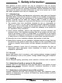
1
5041050/3
IM-P504-04
CH Issue 3
ML3M Monnier Miniature
Compressed Air Lubricator
Installation and Maintenance Instructions
1.Safety information
2.General
product information
3.Installation and
commissioning
4.Operation
5.Spare parts and
Maintenance
IM-P504-04 CH Issue 3
© Copyright 2013
1
Printed in the USA
1. Safety information
Safe operation of these products can only be guaranteed if they are properly
installed, commissioned, used and maintained by qualified personnel (see Section
1.11) in compliance with the operating instructions. General installation and safety
instructions for pipeline and plant construction, as well as the proper use of tools
and safety equipment must also be complied with.
1.1 Intended use
Referring to the Installation and Maintenance Instructions, name-plate and Technical
Information Sheet, check that the product is suitable for the intended use /application.
The products comply with the requirements of the European Pressure Equipment
Directive 97 /23 /EC and fall within the category 'SEP'. It should be noted that
products within this category are required by the Directive not to carry the
mark.
i) The products have been specifically designed for use on compressed air,
which is in Group 2 of the above mentioned Pressure Equipment Directive.
The products’ use on other fluids may be possible but, if this is contemplated,
Spirax Sarco should be contacted to confirm the suitability of the product for
the application being considered.
ii) Check material suitability, pressure and temperature and their maximum and
minimum values. If the maximum operating limits of the product are lower than
those of the system in which it is being fitted, or if malfunction of the product
could result in a dangerous overpressure or overtemperature occurrence, ensure
a safety device is included in the system to prevent such over-limit situations.
iii) Determine the correct installation situation and direction of fluid flow.
iv) Spirax Sarco products are not intended to withstand external stresses that may
be induced by any system to which they are fitted. It is the responsibility of the
installer to consider these stresses and take adequate precautions to minimise
them.
v) Remove protection covers from all connections and protective film from all
name-plates, where appropriate, before installation on steam or other high
temperature applications.
1.2Access
Ensure safe access and if necessary a safe working platform (suitably guarded)
before attempting to work on the product. Arrange suitable lifting gear if required.
1.3Lighting
Ensure adequate lighting, particularly where detailed or intricate work is required.
1.4 Hazardous liquids or gases in the pipeline
Consider what is in the pipeline or what may have been in the pipeline at some
previous time. Consider: flammable materials, substances hazardous to health,
extremes of temperature.
1.5 Hazardous environment around the product
Consider: explosion risk areas, lack of oxygen (e.g. tanks, pits), dangerous gases,
extremes of temperature, hot surfaces, fire hazard (e.g. during welding), excessive
noise, moving machinery.
2
IM-P504-04 CH Issue 3
1.6 The system
Consider the effect on the complete system of the work proposed. Will any proposed
action (e.g. closing isolation valves, electrical isolation) put any other part of the
system or any personnel at risk?
Dangers might include isolation of vents or protective devices or the rendering
ineffective of controls or alarms. Ensure isolation valves are turned on and off in a
gradual way to avoid system shocks.
1.7 Pressure systems
Ensure that any pressure is isolated and safely vented to atmospheric pressure.
Consider double isolation (double block and bleed) and the locking or labelling of
closed valves. Do not assume that the system has depressurised even when the
pressure gauge indicates zero.
1.8Temperature
Allow time for temperature to normalise after isolation to avoid danger of burns.
1.9 Tools and consumables
Before starting work ensure that you have suitable tools and /or consumables
available. Use only genuine Spirax Sarco replacement parts.
1.10 Protective clothing
Consider whether you and /or others in the vicinity require any protective clothing
to protect against the hazards of, for example, chemicals, high /low temperature,
radiation, noise, falling objects, and dangers to eyes and face.
1.11 Permits to work
All work must be carried out or be supervised by a suitably competent person.
Installation and operating personnel should be trained in the correct use of the
product according to the Installation and Maintenance Instructions.
Where a formal 'permit to work' system is in force it must be complied with. Where
there is no such system, it is recommended that a responsible person should know
what work is going on and, where necessary, arrange to have an assistant whose
primary responsibility is safety.
Post 'warning notices' if necessary.
1.12Handling
Manual handling of large and /or heavy products may present a risk of injury. Lifting,
pushing, pulling, carrying or supporting a load by bodily force can cause injury
particularly to the back. You are advised to assess the risks taking into account the
task, the individual, the load and the working environment and use the appropriate
handling method depending on the circumstances of the work being done.
1.13 Residual hazards
In normal use the external surface of the product may be very hot. If used at the
maximum permitted operating conditions the surface temperature of some products
may reach temperatures of 90°C (194°F).
Many products are not self-draining. Take due care when dismantling or removing
the product from an installation (refer to 'Maintenance instructions').
IM-P504-04 CH Issue 3
3
1.14 Freezing
Provision must be made to protect products which are not self-draining against
frost damage in environments where they may be exposed to temperatures below
freezing point.
1.15Disposal
Unless otherwise stated in the Installation and Maintenance Instructions, this
product is recyclable and no ecological hazard is anticipated with its disposal
providing due care is taken.
1.16 Returning products
Customers and stockists are reminded that under EC Health, Safety and
Environment Law, when returning products to Spirax Sarco they must provide
information on any hazards and the precautions to be taken due to contamination
residues or mechanical damage which may present a health, safety or
environmental risk. This information must be provided in writing including Health
and Safety data sheets relating to any substances identified as hazardous or
potentially hazardous.
4
IM-P504-04 CH Issue 3
2. General product information
2.1 General description
The MF2M Monnier miniature compressed air filter provides high quality compressed air for
general purpose pneumatic applications.
Principal features:
- Once set compensates for varying air flowrates.
- Easy setting of oil / air ratio: approximately 5% of each oil drop enters the air stream.
- Tamper-proof feature; prevents unauthorised adjustment.
- Non-return valve in oil pick up system ensures lubrication for short air flows.
- Polycarbonate bowl.
-External black anodised finish.
Optional extras:
For further technical information regarding the following options see page 6:
- Type 3 mounting bracket.
- Easy fit stainless steel bowl guard.
2.2 Sizes and pipe connections
¼" screwed BSP (BS 21-Rp).
Fig. 1 ML3M Monnier miniature compressed air lubricator
2.3 Operating limits
Maximum
pressure /temperature
Polycarbonate bowl 10 bar g @ 50°C (145 psi g @ 122°F)
Metal bowl
17 bar g @ 80°C (246.5 psi g @ 176°F)
2.4Materials
Part
Material
Head
Aluminium
Bowl
Polycarbonate
Capacity valveAcetal
Seals
Nitrile rubber
Bowl guard (optional extra)
Stainless steel
IM-P504-04 CH Issue 3
5
3. Installation and commissioning
Note: Before actioning any installation observe the 'Safety information' in Section 1.
Referring to the Installation and Maintenance Instructions, name-plate and Technical
Information Sheet, check that the product is suitable for the intended installation.
3.1 Specific product safety information
Polycarbonate bowls may be attacked by phosphate ester based fluids, solvents, chemical
cleaners, carbon tetrachloride, etc. These and any other substances should not be allowed
to come into contact with this component. Certain compressor lubricating oils also contain
additives harmful to polycarbonate. Where there is any doubt we recommend, in the interests
of personal safety, that bowl guards or metal bowls be fitted.
3.2 General information
ML3M
Dimensions (approximate) in mm and kg
A B B1C EE1Bowl
capacity Weight
4813013938 10 40 20 0.15
Type 3 mounting bracket
This is a zinc plated, mild steel angle bracket
which can be attached to any flat surface by
means of screws or bolts.
C
A
Fig. 3
Bowl
guard
B
Dimensions (approximate) in mm and kg
A
B
C
D
E
F
7550256513 20
F
E
Withdrawal distance: E
D
Without
bowl guard
Withdrawal distance: E1 With
bowl guard
Bowl guard
C
In the interest of safety Spirax Sarco
recommend that a bowl guard should be
fitted - see Section 3.1, Specific product
safety information.
B
A
Fig. 4
Fig. 2
6
IM-P504-04 CH Issue 3
3.3Installation
3.3.1 The unit should be fitted in horizontal pipework with the bowl vertically downwards.
3.3.2 Adequate space should be provided around the unit to allow easy access for routine
servicing requirements (see Figure 2 for withdrawal distances).
3.3.3 Connect the unit so that the airflow is in the direction indicated by the arrow on the body.
3.3.4 The unit should be installed as close as possible to the equipment it is serving.
3.3.5 An MF2M Monnier filter should be fitted upstream to prevent any contaminants reaching
the system to be lubricated.
3.3.6 The polycarbonate bowl may be fitted with a bowl guard.
3.4 To adjust lubrication rate
Tamper-proof
The normal oil requirement for most pneumatic
systems is one drop of oil for every 5 dm³ of
free air used. To simplify setting up the oil
drip rate, particularly for low air flows, only a
proportion (approximately 5%) of the oil drops
as seen in the sight dome (3) is carried into
the system. To increase the oil rate, turn the oil
adjustment screw (4) anticlockwise.
" diameter ball
6
6
4
3
3.5 To fill bowl
Turn off the air supply. Remove the bowl guard
if fitted. Unscrew the bowl. Clean the bowl if
required. Refill the bowl with suitable lubricant
(see Section 3.6), to the level shown (bottom of
bowl thread) and refit carefully, with bowl seal
(7). A good hand tight joint between the bowl
and body is correct. Turn on the air supply.
3.6Lubricant
7
The oil used must be compatible with the
equipment being served by the lubricator,
and with the materials of construction of the
lubricator itself. Generally the oil will be of the
free fogging type in the viscosity range of 7.5
to 64 centistokes (45 to 280 seconds Redwood
No. 1) at 38°C (100°F). Use only new clean oils.
3.7 Tamper-proof feature
As standard, each lubricator is supplied with
a
" diameter tamper-proof ball (6) that
may be pressed or tapped into the top of the
sight dome adjustment area after the oil rate
has been set (See Figure 5). This prevents
any further adjustment by unauthorized
personnel.
IM-P504-04 CH Issue 3
Fig. 5
7
4. Operation
4.1 Principle of operation
Insert tamper-proof
" diameter ball as indicated
Monnier lubricators are used
to maintain the proper ratio of
oil and air and to maximize the
performance and guarantee long
life of pneumatic machinery.
Once the oil rate has been set,
a Monnier lubricator provides
reliable automatic lubrication. The
Monnier design ensures efficient
and dependable performance.
The Monnier Venturi valve (1)
automatic ally maint ains the
ratio of oil to air that the user
selects. It assures lubrication
even at the lowest possible air
flow (see Capacities on page 9).
By automatically increasing the
air pressure behind the oil in the
main reservoir (2) in proportion to
the increased air flow, the Venturi
valve provides the desired degree
of lubrication regardless of air
flowrate.
The Monnier sight dome (3)
is moulded from transparent
polycarbonate that can be viewed
at a full 360°. It includes an
adjustment screw (4) for setting
the oil rate, and a sight-feed
tube (5) where the oil can be
visually measured, drop by drop.
As standard, each lubricator is
supplied with a
" diameter
tamper-proof ball (6) that may be
pressed or tapped into the top of
the sight dome adjustment area
after the oil rate has been set. This
prevents any further adjustment
by unauthorized personnel.
6
6
4
3
5
1
Max.
oil
level
2
Fig. 6 Operation
8
IM-P504-04 CH Issue 3
4.2 Capacities
Minimum flowrate scfm
Pressure psi
Pressure bar
Minimum flowrate dm /s
3
Air flow scfm
Pressure drop psi
Pressure drop bar
Air flow dm /s
3
IM-P504-04 CH Issue 3
9
5. Spare parts and maintenance
5.1 Spare parts
The spare parts available are detailed below. No other parts are supplied as spares.
Available spares
Bowl assembly
Sight dome assembly
Bowl guard assembly (optional extra)
A, B
C, D, E
X, Y
Note: In the interests of safety Spirax Sarco
recommend that a bowl guard (an optional
extra) should be fitted to polycarbonate bowls.
How to order spares
Always order spares by using the desciption
given in the column headed 'Available spares'
and state the size and type of unit.
Example: 1 off Bowl assembly for a ¼" ML3M
Monnier miniature compressed air filter.
C
D
E
5.2Maintenance
To service the filter (no tools required):
- Isolate
the main air supply and vent the
system pressure to atmosphere.
- Remove the bowl guard (X) if fitted.
- By hand, unscrew the bowl (A) slowly
allow any residual pressure to vent.
B
to
- Clean the bowl (A) using soap and water
only (do not use solvents or proprietary
cleaners) and wipe dry with a lint free cloth.
- Reassemble, having filled the bowl (A) to
the appropriate level (bottom of the bowl
thread) with the clean correct oil - See
Section 3.6.
A
- Hand tighten the bowl (A) firmly.
- If the sight dome assembly (C,
D and E)
has been removed, clean using soap
and water only (do not use solvents or
proprietary cleaners) and wipe dry with a
lint free cloth.
- Reassemble ensuring the two 'O' rings
(D and E) are correctly seated. Do not
over-tighten the bowl or sight dome
assembly.
Y
X
Fig. 7
Spare parts
10
IM-P504-04 CH Issue 3
IM-P504-04 CH Issue 3
11
12
IM-P504-04 CH Issue 3