1
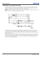
Mirage J Series User Manual 020-100708-01 Mirage J Series User Manual 020-100708-01 NOTICES COPYRIGHT AND TRADEMARKS © 2011 Christie Digital Systems USA, Inc. - All rights reserved. All brand names and product names are trademarks, registered trademarks or trade names of their respective holders. REGULATORY The product has been tested and found to comply with the limits for a Class A digital device, pursuant to Part 15 of the FCC Rules. These limits are designed to provide reasonable protection against harmful interference when the product is operated in a commercial environment. The product generates, uses, and can radiate radio frequency energy and, if not installed and used in accordance with the instruction manual, may cause harmful interference to radio communications. Operation of the product in a residential area is likely to cause harmful interference in which case the user will be required to correct the interference at the users own expense. This Class A digital apparatus complies with Canadian ICES-003. Cet appareil numérique de la classe A est conforme à la norme NMB-003 du Canada. 㧊 ₆₆⓪ 㠛ⶊ㣿 (A ) 㦒⪲ 㩚㧦䕢㩗䞿❇⪳㦚 䞲 ₆₆㧊㡺┞ 䕦ⰺ㧦 ⡦⓪ ㌂㣿㧦⓪ 㧊㩦㦚 㭒㦮䞮㔲₆ ⧒Ⳇ , Ṗ㩫 㣎㦮 㰖㡃㠦㍲ ㌂㣿䞮⓪ ộ㦚 ⳿㩗㦒⪲ 䞿┞┺ . GENERAL Every effort has been made to ensure accuracy, however in some cases changes in the products or availability could occur which may not be reflected in this document. Christie reserves the right to make changes to specifications at any time without notice. Performance specifications are typical, but may vary depending on conditions beyond Christie's control such as maintenance of the product in proper working conditions. Performance specifications are based on information available at the time of printing. Christie makes no warranty of any kind with regard to this material, including, but not limited to, implied warranties of fitness for a particular purpose. Christie will not be liable for errors contained herein or for incidental or consequential damages in connection with the performance or use of this material. The product is designed and manufactured with high-quality materials and components that can be recycled and reused. This symbol means that electrical and electronic equipment, at their end-of-life, should be disposed of separately from regular waste. Please dispose of the product appropriately and according to local regulations. In the European Union, there are separate collection systems for used electrical and electronic products. Please help us to conserve the environment we live in! Canadian manufacturing facility is ISO 9001 and 14001 certified. GENERAL WARRANTY STATEMENTS For complete information about Christie limited warranty, please contact your Christie dealer. In addition to the other limitations that may be specified in Christie limited warranty, the warranty does not cover: a. Damage occurring during shipment, in either direction. b. Projector lamps (See Christie separate lamp program policy). c. Damage caused by use of a projector lamp beyond the recommended lamp life, or use of a lamp supplied by a supplier other than Christie. d. Problems caused by combination of the product with non-Christie equipment, such as distribution systems, cameras, video tape recorders, etc., or use of the product with any non-Christie interface device. e. Damage caused by misuse, improper power source, accident, fire, flood, lightening, earthquake or other natural disaster. f. Damage caused by improper installation/alignment, or by product modification, if by other than a Christie authorized repair service provider. g. For LCD projectors, the warranty period specified applies only where the LCD projector is in “normal use.” “Normal use” means the LCD projector is not used more than 8 hours a day, 5 days a week. For any LCD projector where “normal use” is exceeded, warranty coverage under this warranty terminates after 6000 hours of operation. h. Failure due to normal wear and tear. PREVENTATIVE MAINTENANCE Preventative maintenance is an important part of the continued and proper operation of your product. Please see the Maintenance section for specific maintenance items as they relate to your product. Failure to perform maintenance as required, and in accordance with the maintenance schedule specified by Christie, will void the warranty. Table of Contents 1: Introduction 1.1 Projector Overview......................................................................................................................1-1 2: Operation 2.1 3D ................................................................................................................................................2-1 A: Menu Tree A.1 Mirage J Series Menu Tree.........................................................................................................A-1 B: GPIO B.1 GPIO Port....................................................................................................................................B-1 Mirage J Series User Manual 020-100708-01 Rev. 1 (11-2011) i 1 Introduction Every effort has been made to ensure the information in this document is accurate and reliable; however, due to constant research the information in this document is subject to change without notice. 1.1 Projector Overview The Mirage J Series projectors provide a powerful combination of high resolution video/graphics, 3 chip 1080p HD, SXGA+, and WUXGA resolutions, high brightness and high contrast ratios to produce flawless, realistic three-dimensional images for simulation, virtual reality and other stereographic related applications. This document applies to the following projector models: Table 1.1 Mirage J Series Projectors Model Name Part Number MIRAGE DS+8K-J 132-004127-XX MIRAGE HD7K-J 132-005128-XX MIRAGE WU7K-J 132-006129-XX MIRAGE S+14K-J 132-010124-XX MIRAGE HD14K-J 132-011125-XX MIRAGE WU14K-J 132-012126-XX MIRAGE S+18K-J 132-013127-XX MIRAGE HD16K-J 132-014128-XX MIRAGE S+22K-J 132-016120-XX MIRAGE HD20K-J 132-017121-XX MIRAGE WU20K-J 132-018122-XX Mirage J Series User Manual 020-100708-01 Rev. 1 (11-2011) 1-1 2 Operation 2.1 3D The Mirage J Series projector is capable of displaying stereoscopic 3D video sources. The Mirage J Series relies on additional hardware; such as stereo emitters and glasses to complete the display system. Images generated from a stereo 3D-video source consist of a series of images (frames) that alternate quickly between two slightly different view points, corresponding to your left and right eye. When these frames are displayed fast enough and viewed with special stereo glasses synchronized to the left/right (L/R) changes, the resulting image appears with the same depth and perspective that is sensed in the real world. NOTE: The type of special glasses can be active stereo or passive stereo glasses depending on the type of stereo controllers and screen used. 2.1.1 Requirements Stereo 3D applications require a stereo 3D-capable source, special hardware/software setups (described below), the 3D Settings menu option to control the projector processing, synchronizing and displaying of your stereoscopic 3D source material. Hardware: • Christie 3D version of Mirage J Series projector. • Christie 3D Stereo Sync Cable (required for 3D Mirage J Series models; ensures minimum frame delay). This General Purpose Input Output (GPIO) cable is standard with all Mirage J Series projectors. NOTE: See Appendix B: GPIO. • A source, usually a computer with a stereo 3D graphics card capable of displaying progressive scan (alternating frames) of OpenGL quad buffered stereo 3D applications (suggested cards include ATI or NVIDIA), and running under Windows, Linux, IRIX, HPUX, OSX or Solaris operating systems. • Emitter for controlling active shutter glasses. • An appropriate qualified device that mounts in front of the lens of the projector that will process the light from the lens into a passive polarized light. Contact your Immersive dealer for more information. Software or content: • Any 3D computer software that supports active or sequential 3D stereo on a supported computer/graphic card. • A video stream from video source that has been prepared to be sequential content. Supports stereo signals prepared on either a compatible Dual and Single link HDSDI format. • Compatible passive dual channel sources, providing each signal type is frame locked and the input connections are identical. Mirage J Series User Manual 020-100708-01 Rev. 1 (11-2011) 2-1 Section 3: Operation CONNECTING THE 3D STEREO SYNC CABLE This GPIO cable provides the means for synchronizing the various components in your 3D system. Your source, projector display output, and emitters or 3D passive filter system can then operate together with precision to minimize cross-talk and color artifacts. Connect as shown below. NOTE: For Mirage J Series models, inputs A and B are not required, but recommended to ensure that stereo is configured correctly, especially for multiple projector setups. Connecting Two Stereo 3D Sync Inputs (Recommended for multiple sources). Connect your video card’s stereo 3D sync cable to either Input A or either Input B on the 3D Stereo Sync Cable. These inputs are provided to allow you to connect two different Stereo 3D sources and conveniently switch the display backand-forth between them. Connecting One Stereo 3D Sync Output Connect the 3D Stereo Sync Cable output to your stereo 3D sync emitter or 3D passive filter system, PZE device. The L/R switching of the device can then be synchronized according to the controlling signal of choice—either the source input signal or the internally generated signal—as set in the 3D Settings menu. 2-2 Mirage J Series User Manual 020-100708-01 Rev. 1 (11-2011) Section 3: Operation 2.1.2 Active and Passive Stereo 3D Configurations Typical hardware configurations for active and passive Stereo 3D systems are shown in Figure 1 - Mirage J Series - Typical Stereo 3D Configuration: With Active Glasses and Figure 2 - Mirage J Series - Typical Stereo 3D Configuration: With Passive Glasses. Figure 1 - Mirage J Series - Typical Stereo 3D Configuration: With Active Glasses Figure 2 - Mirage J Series - Typical Stereo 3D Configuration: With Passive Glasses Appropriate Stereo 3D Source: Use stereo 3D application software with your 3D video source (usually a workstation or PC). The source must provide a separate stereo 3D synchronization signal that precisely controls when the left/right fields are visible through the glasses of the viewer. This separate signal is usually provided using a VESA 3 pin stereo port. Mirage J Series User Manual 020-100708-01 Rev. 1 (11-2011) 2-3 Section 3: Operation IR Emitter/3D Passive Filter System: In response to an incoming sync signal, the emitter emits L/R infrared signals to a receiver in active 3D shutter glasses, causing the L/R shutters to alternately open and close for active stereo 3D applications. Likewise, a 3D passive filter system placed in front of the lens responds to an incoming sync signal and alternately polarizes the L/R frames viewed with passive glasses for active stereo 3D applications. Connecting one of the 3D Stereo Sync Cable outputs to an emitter/3D passive filter system allows you to synchronize your stereo 3D display with the glasses. Glasses (Active/Passive): Active glasses differ in speed and performance. Consult the documentation for your glasses and keep their specifications in mind when configuring your source signal. The input signal must be optimized for the available shutter speed to prevent obvious “ghosting” of image content (known as cross-talk in stereo 3D applications) and other more subtle color artifacts. Such problems indicate that the eyes are detecting portions of the opposing frame due to an “out-of-sync” system, and can occur in either active or passive stereo 3D configurations. Adjust the Dark Interval setting to reduce ghosting. In the 3D Settings menu, the correct “3D Stereo Sync Delay” setting should help to synchronize glasses with the displayed images. NOTE: In a passive system, where glasses do not have shutters and instead depend on the speed and accuracy of the 3D passive filter system, the signal must be synchronized to the projector via the 3D Stereo Sync Cable. 4.2 3D SETTINGS Use the options in the 3D Settings menu to make the timing adjustments necessary for realistic simulation and 3D images. 3D State: Informs you what state the projector is in: Off, Missing Secondary Signal, Not Frame Locked, Secondary Frequency Mismatch, High Bandwidth Not Supported, Stereo Sync Not Detected, Stereo Sync Invalid, and Invalid Frequency. NOTE: This is read only. 2-4 Mirage J Series User Manual 020-100708-01 Rev. 1 (11-2011) Section 3: Operation 3D Mode: Select the mode of your 3D operation. Off: 3D operation is disabled. Auto 3D: Attempts to automatically determine which 3D mode to use based on auxiliary video data, e.g. HDMI info frame. Native 3D: All content is shown at a native frame rate of 96 - 120 Hz input and output. Frame Doubled 3D: 3D Content from a single 48-60Hz signal (24/30Hz per eye) is displayed twice to provide a 3D content to be viewed at 96-120Hz. Dual Input 3D: Content from two independent 48-60Hz ‘passive’ frame locked sources are interleaved into a native 96-120Hz native frame rate. This requires and optional input module and both signals must be from the same signal type. Side-by-Side 3D: Content is transmitted with each eye beside each other in a single frame, and is extracted and scaled appropriately to show in an alternate-frame sequence. Typically used for broadcast 3D-TV. Top-and-Bottom 3D: Content is transmitted with each eye above one another in a single frame at half resolution, and is extracted and scaled to show in an alternate-frame sequence. Frame Packed 3D: Content is transmitted with each eye at full resolution in a double-sized frame, and is extracted to show in an alternate-frame sequence. Typically used for Blu-ray 3D movies and 3D video gaming. Triple-Flash 3D: 3D Content from a single 48Hz signal (24Hz per eye) is displayed three times to provide you a 3D image to be viewed at 144Hz. Dark Interval: Artificially increases the amount of dark time between displayed frames for stereoscopic 3D images. Higher settings provide more time for shutters in 3D glasses to open and close, ensuring that each eye sees the full display intended for it. Symptoms of cross talk or color artifacts can indicate the need for adjustment. The Dark Interval range of adjustment depends on the vertical frequency of your source-the higher the frequency, the smaller the range. Default setting is 2.3ms. 3D Sync Input: The 3D sync signal is generated by the 3D source to insure left/right eye content is synchronized to the projector and you. The projector has the ability to physically connect to two different sources. Ensure that the correct 3D sync input is selected (either Input A or Input B) with each 3D signal source. If none/internal is selected the projector will generate the sync internally and content will be displayed; however, there is a 50% chance that the content will be displayed with the left/right eyes swapped (from the remote, press FUNC 6-9 to swap the eyes). NOTE: This function is not used in Interleaved 3D mode. Each eye receives a selected input and no 3D sync input is required. Mirage J Series User Manual 020-100708-01 Rev. 1 (11-2011) 2-5 Section 3: Operation 3D Sync Output: This option defines whether the 3D Sync is output and controls how it is processed. It is only valid when an optional cable is used to connect stereo 3D signals to the projector via the GPIO port. When there is no 3D signal, Sync Output should be 'Off'. Typically only the last projector in the 3D Stereo cable chain is connected to the emitter and should specify 'To Emitter'. All other projectors should select 'To Next Input' if other projectors are used in the chain. 3D Stereo Sync Delay: Adjust the output 3D emitter delay (in milliseconds) to match the active glasses to the L/R frames of the projector. Proper adjustment of this delay will eliminate cross talk and odd colors caused by timing differences between the glasses and the projected image. Your specified delay is added after sync locking. 3D Test Pattern: Enables a 3D test pattern for diagnostics. The scrolling diagonal lines indicate how well left and right are synchronized. If ghosting is occurring the input may have to be switched or inverted. Adjustments to the emitter delay can also help correct the synchronization. To verify that your 3D is setup correctly, a small set of “L”s will be visible when you close your right eye and a small set of “R”s will be visible when you close your left eye. Frame Locking: Enable or disable Frame Lock. When set to Frame Lock, if possible output image frames are locked to the input. When Locked, the output is always locked to the primary input and never the secondary image, when using Dual input 3D. Free Run sets the output to close to 60Hz for all sources. This control must be set to locked if a 3D-Stereo signal is used. Set Frame Delay: Delays the output signal timing relative to the input signal timing by a fraction of a frame, and up to several frames. The minimum latency can vary based on the amount of scaling applied to the image. When using keystone or warping, an additional latency is required, depending on the amount of warp. The control is only available when the input signal is frame locked. In free run mode, or in cases where the signal cannot be frame locked, the minimum latency defined by the scaling and keystone/warp is applied to the signal. Actual Frame Delay: Displays the actual frame delay reading. Full Screen Eye-Motion Filter: Check this control to apply the Eye-Motion Filter to the entire screen, rather than applying just to the edge blending regions. Helps with posterization effects, sometimes seen in color ramps when viewing stereoscopic images. Eye-Motion Filter: Adjust this filter to reduce saccadic eye-motion artifacts, sometimes noticeable in edge blending regions. Too much filtering may result in loss of detail. For best results, adjust this setting while positioned at the nominal screen-viewing distance. Edit Secondary Channel Settings: When using Dual Input 3D, this allows you the option to independently control primary and secondary channel settings, or to use the same setting for both links. By default, this control is unchecked, meaning any settings applied to the primary input will also be applied to the secondary input. In this case, the secondary channel settings cannot be set. When checked, the secondary channel settings become editable. Main Input: Select an input from the drop-down list. Secondary Input: Select an input to be used as secondary input in a Dual Input 3D setup. Display 3D Message Boxes: Enable/Disable message boxes that are triggered by 3D setup. NOTE: No message box is shown in “Off” and “Valid” state. 2-6 Mirage J Series User Manual 020-100708-01 Rev. 1 (11-2011) Section 3: Operation 2.1.3 Example of 3D Multiple Display Setup The following instructions is an example of a multiple display setup or refer to Figure 2-3 Example of 3D Multiple Display Setup. 1. Setup the warp and blends for the projector. 2. If necessary, shift or scale your image to fit the display. 3. Set all projectors to the largest minimum Frame Delay value that the worst case projector in the array can achieve. 4. Enable 3D mode on all projectors. Using the remote >Main Menu>Image Settings>Advanced Image Settings>3D Settings 5. Set all projectors 3D Sync Output to “Next Projector” with the exception of the last projector; select “To Emitter.” 6. Connect the PC emitter sync to either Input A (or B) on the 3D dongle. 7. Connect the output from the 3D dongle in the first projector to Input A (or B) on the next projector in the array. 8. Repeat the same procedure to all projectors except the last projector in the array. Route the Sync output from the 3D dongle to the emitter. NOTE: For the last projector, route the sync input. 9. If your emitter has a reverse setting ensure it is set to the Off position. 10. Set all projectors to 3D Sync Input A (or B) depending on your selection in Step 6 & 7. 11. Apply the 3D test pattern to all projectors. 12. Put on your 3D glasses. 13. When 3D is setup correctly, a small set of the letter L is visble by closing your right eye and a small set of the letter R is visible when closing your left eye. 14. If necessary, adjust the dark interval settings until the test pattern sees the least amount of ghosting for each projector. 15. Adjust the 3D Sync Delay on the last projector in your array to match the optimal sampling point for the glasses being used. NOTE: The default auto setup value is typically good for all glasses. 16. Turn off the 3D test pattern on each projector. Your 3D content should look optimal. Mirage J Series User Manual 020-100708-01 Rev. 1 (11-2011) 2-7 Section 3: Operation FIGURE 2-3 EXAMPLE OF 3D MULTIPLE DISPLAY SETUP 2-8 Mirage J Series User Manual 020-100708-01 Rev. 1 (11-2011) Appendix A: Menu Tree A.1 Mirage J Series Menu Tree Mirage J Series User Manual 020-100708-01 Rev. 1 (11-2011) A-1 Main Menu 1. Size & Position 2. Image Settings 3, Channel Setup 4. Configuration 5. Lamp 6. Status 7. Secondary Input & Switching 8. Language 9. Test Pattern Advanced Main Mirage J Series User Manual 020-100708-01 Rev.1 (11-2011) Press <Enter> on a channel Secondary Image Settings 1. Contrast 2. Brightness 3. Reserved 4. Color Space 5. Secondary Video Options 6. Secondary Input Levels 7. Secondary Advanced Image Settings Secondary Input & Switching 1. Main Input 2. Secondary Input 3. Swap Main & Secondary inputs 4. PIP Enable 5. PIP Window Options 6. Secondary Size & Position 7. Secondary Image Settings 8. Fade Time 9. Frame Locking 10. Auto Input Searching 11. HDMI Output Loop Source 12. Standby Active Loop-Through Lamp 1. Lamp Mode 2. Power 3. Intensity 4. Optical Aperture 5. Warn when lamp reaches (hours) 6. Lamp 1 s/n 7. Change Lamp 8. Lamp 1 History See Page A4 for Configuration Channel Setup This is a list of all of the channels that have been defined for this projector. Image Settings 1. Contrast 2. Brightness 3. Reserved 4. Color Space 5. Video Options 6. Input Levels 7. Advanced Image Settings Size & Position 1. Resize Presets 2. Size 3. Vertical Stretch 4. Pixel Track 5. Pixel Phase 6. H-Position 7. V-Position 8. Keep Aspect on Auto Setup 9. Blanking Secondary Advanced Image Settings 1. Secondary Gamma Settings 2. Secondary Detail Settings 3. Secondary Noise Reduction Settings 4. Secondary Color Settings 5. Reserved 6. Reserved Secondary Input Levels 1. Auto Input Level 2. Red<Pr> Blacklevel 3. Red<Pr> Input Drive 4. Green<Y> Blacklevel 5. Green<Y> Input Drive 6. Blue<Pb> Blacklevel 7. Blue<Pb> Input Drive 8. Auto Color Enable 9. Clamp Location 10. Peak Detector 11. Color Enable Secondary Video Options 1. Enable Decoder AGC 2. Video Standard 3. Input Video Black 4. Color 5. Tint 6. Filter 7. Sampling Mode 8. Film Mode Detect 9. Chroma/Luma Delay 10. Adaptive Contrast 11. Reserved 12. RGB Quantization Range Secondary Size & Position 1. Resize Presets 2. Size 3. Vertical Stretch 4. Pixel Track 5. Pixel Phase 6. H-Position 7. V-Position 8. Keep Aspect on Auto Setup 9. Secondary Blanking Secondary Color Settings 1. Select Color Adjustment 2. Color Temperature Secondary Noise Reduction Settings 1. Noise Reduction 2. Block Artifact Reduction 3. Mosquito Noise Reduction 4. Reserved 5. Full Screen Eye-Motion Filter 6. Eye-Motion Filter Secondary Detail Settings 1. Detail 2. Texture Enhancement 3. Detail Threshold 4. Detail Overshoot 5. Reserved Secondary Gamma Settings 1. Gamma Correction 2. Gamma 3. Gamma Function 4. Gamma Slope Secondary Blanking Active Input Window 1. Top Blank 2. Bottom Blank 3. Left Blank 4. Right Blank Channel Edit: Card Type H-Frequency V-Frequency Interlaced Sync Source 1. Name 2. Channel 3. Slot 4. Input 5. In Menu 6. Auto Select 7. Locked 8. Previous Channel 9. Next Channel 3D Settings 3D State 1. 3D Mode 2. Dark Interval 3. 3D Sync Input 4. Invert 3D Input 5. 3D Sync Output 6. 3D Stereo Sync Delay 7. 3D Test Pattern 8. Test Pattern 9. Set Frame Delay 10. Actual Frame Delay 11. Full Screen Eye-Motion Filter 12. Eye-Motion Filter 13. Edit Secondary Channel Settings 14. Main Input 15. Secondary Input 16 Display 3D Message Boxes Color Settings 1. Select Color Adjustment 2. Color Temperature Noise Reduction Settings 1. Noise Reduction 2. Block Artifact Reduction 3. Mosquito Noise Reduction 4. Split Screen 5. Full Screen Eye-Motion Filter 6. Eye-Motion Filter Detail Settings 1. Detail 2. Texture Enhancement 3. Detail Threshold 4. Detail Overshoot 5. Split Screen Gamma Settings 1. Gamma Correction 2. Gamma 3. Gamma Function 4. Gamma Slope Change Lamp 1. New lamp Serial Number 2. Change Lamp PIP Window Options 1. PIP Position Presets 2. PIP Window Size 3. PIP H-Position 4. PIP V-Position 5. PIP Border Width 6. PIP Border Color Input Old Lamp Serial Number 1. Old Lamp Serial Number 2. Continue 3. Abort Select Channel Operation Edit Channel Copy Channel Delete Channel Delete Unlocked Only Delete All Channels Advanced Image Settings 1. Gamma Settings 2. Detail Settings 3. Noise Reduction Settings 4. Color Settings 5. Reserved 6. 3D Settings Input Levels 1. Auto Input Level 2. Red<Pr> Blacklevel 3. Red<Pr> Input Drive 4. Green<Y> Blacklevel 5. Green<Y> Input Drive 6. Blue<Pb> Blacklevel 7. Blue<Pb> Input Drive 8. Auto Color Enable 9. Clamp Location 10. Input Peak Detector 11. Color Enable Video Options 1. Enable Decoder AGC 2. Video Standard 3. Input Video Black 4. Color 5. Tint 6. Filter 7. Sampling Mode 8. Film Mode Detect 9. Chroma/Luma Delay 10. Adaptive Contrast 11. Split Screen 12. RGB Quantization Range Blanking Active Input Window 1. Top Blank 2. Bottom Blank 3. Left Blank 4. Right Blank Appendix A: Menu Tree A-3 A-4 Configuration 1. Language 2. Output Options 3. Lens Settings 4. Power Management 5. Date & Time 6. Menu Preferences 7. Communications 8. Geometry & Color 9. Diagnostics & Calibration 10. Service 11. Option Card Settings 12. Reserved Func Help = disables Keystone, Edge Blending and Brightness Uniformity without changing the settings associated with them. Func 0 9 = If pressed from Status page, opens Service Status page (For Service personnel only) Press FUNC followed by two numeric numbers to enable a specific color or colors in the display: Func 6 0 = white Func 6 1 = red Func 6 2 = green Func 6 3 = blue Func 6 4 = yellow Func 6 5 = cyan Func 6 6 = magenta Func 6 7 = white Func 6 8 = Func 6 9 = invert (3D only) Main Menu 1. Size & Position 2. Image Settings 3, Channel Setup 4. Configuration 5. Lamp 6. Status 7. Secondary Input & Switching 8. Language 9. Test Pattern Advanced Menu continued Menu will be filled with types that match cards plugged in Option Card Settings 1. Video Decoder Input card 2. Dual HD/SDI Input Card 3. Twin HDMI Input Card 4. Analog BNC Input Card See Page A5 for: 8. Geometry & Color 9. Diagnostics & Calibration 10. Service Communications 1. Serial (RS-232 IN) Options 2. Serial (RS-232 OUT) Options 3. Serial (RS-422) Options 4. Projector Address 5. Network Routing 6. Ethernet Settings 7. Broadcast Keys 8. Front IR Enabled 9. Rear IR Enabled 10. Wired Keypad Enabled 11. DMX / ArtNet Settings 12. SNMP Menu Preferences 1. Large Menu Font 2. Menu Location 3. Horizontal Shift 4. Vertical Shift 5. Display Automatic Message Boxes 6. Display User Message Boxes 7. Reserved 8. Display Error Messages 9. Logo Screen Preferences 10. OSD Transparency 11. Menu Type 12. Splash Screen 13. Cascading Menus Date & Time 1. Date 2. Time Power Management 1. LCD Backlight 2. LCD Backlight Timer 3. LCD Backlight Level 4. Auto Power Up 5. Auto Shutdown Enable 6. Turn Off Image After (min) 7. Enter Standby After (min) 8. Reserved 9. Over-Temp Fan Assist Lens Settings 1. Intelligent Lens System 2. Manual Zoom/Focus 3. Calibrate 4. Lock all Lens Motors 5. Calibrate on New Lens 6. Calibrate on Startup 7. Home Position Calibration Status Output Options 1. Screen Image Orientation 2. Reserved 3. Reserved 4. Frame Locking 5. Set Frame Delay 6. Actual Frame Delay 7. Free Run Frequency 8. Fade to Black Time 9. HDMI Output Loop Source Analog BNC Input card 1. Connector Grounding 2. Red Odd Pixel Offset 3. Green Odd Pixel Offset 4. Blue Odd Pixel Offset 5. Red Odd Pixel Gain 6. Green Odd Pixel Gain 7. Blue Odd Pixel Gain 8. Odd Pixel Phase Offset 9. Pixel Phase 10. Input Level Detector 11. Level Detector Threshold 12. Auto Color Enable 13. Color Enable Twin HDMI Input card 1. EDID Timings For Input 1 2. Tx Mode for Output 1 3. EDID Timings For Input 2 4. Tx Mode for Output 2 Dual Link DVI Input card 1. EDID Timings for Input 1 2. EDID Timings for Input 2 Dual HD/SDI Input card 1. Dual Link Mode Video Decoder Input card 1. Grouped-Inputs Mode 2. Connector 1 Grounding 3. Connector 2 Grounding 4. Connector 3 Grounding 5. Connector 4 Grounding 6. Connector 5 Grounding 7. Connector 6 Grounding Trap Configuration 1. Lamp Life 2. Lamp Fault 3. Fan Stall 4. Thermal Sensors 5. Power 6. Video signal lost/detected 7. Lamp Door SNMP 1. SNMP Read Community 2. SNMP Location 3. Trap IP Address 1 4. Trap IP Address 2 5. Trap IP Address 3 6. Email Recipient 1 7. Email Recipient 2 8. Email Recipient 3 9. Email From: Address 10. SMTP Server IP Address 11. Trap Configuration DMX / ArtNet Settings 1. DMX Interface 2. DMX Personality 3. Base Channel 4. Software Termination 5. Artnet Universe 6. Artnet Subnet 7. Input Noise Filter 8. Host name Ethernet Settings 1. IP Configuration 2. IP Address 3. Subnet Mask 4. Gateway 5. TCP Port 6. Host name 7. Domain name MAC Address Serial (RS-422) Options 1. Baud Rate (RS-422) 2. Serial Flow Control (RS-422) 3. Serial Mode (RS-422) 4. Serial Protocol (RS-422) Serial (RS-232 OUT) Options 1. Baud Rate (RS-232 OUT) 2. Serial Flow Control (RS-232 OUT) 3. Serial Mode (RS-232 OUT) 4. Serial Protocol (RS-232 OUT) Serial (RS-232 IN) Options 1. Baud Rate (RS-232 IN) 2. Serial Flow Control (RS-232 IN) 3. Serial Mode (RS-232 IN) 4. Serial Protocol (RS-232 IN) Logo Screen Preferences 1. Splash Screen Setup 2. Splash Screen 3. Show Logo Image 4. Horizontal Position 5. Vertical Position Appendix A: Menu Tree Mirage J Series User Manual 020-100708-01 Rev.1 (11-2011) Main Menu 1. Size & Position 2. Image Settings 3, Channel Setup 4. Configuration 5. Lamp 6. Status 7. Secondary Input & Switching 8. Language 9. Test Pattern Advanced Main Menu continued Configuration 1. Language 2. Output Options 3. Lens Settings 4. Power Management 5. Date & Time 6. Menu Preferences 7. Communications 8. Geometry & Color 9. Diagnostics & Calibration 10. Service 11. Option Card Settings 12. Reserved Mirage J Series User Manual 020-100708-01 Rev.1 (11-2011) Requires the service password to enter this menu Service 1. Reserved 2. Reserved 3. Color Primary Settings 4. Reserved 5. Reserved 6. Replace Backplane 7. Remote Access Level 8. Restore Factory Defaults 9. Erase Data Files 10. Delete All Real Time Events 11. Status Diagnostics & Calibration 1. Test Pattern 2. Grey Level 3. Freeze Image 4. Color Enable 5. Input Peak Detector 6. Input Level Detector 7. Level Detector Threshold 8. Aspect Ratio Overlay 9. Test Pattern Color Swap 10. Calibrate LiteLoc Calibration Status 11. Freeze Image During Auto Setup Geometry & Color 1. Test Pattern 2. Geometry Correction 3. Brightness Uniformity 4. Edge Blending 5. Color Adjustments by X,Y 6. Color Saturation 7. Black Level Blending 8. Default Color Adjustment 9. Reserved 10. Tiling Setup See Page A4 for: 1. Language 2. Output Options 3. Lens Settings 4. Power Management 5. Date & Time 6. Menu Preferences 7. Communications 11. Option Card Settings See Page A3 for Lamp Color Adjustments by X,Y 1. Select Color Adjustment 2. Color Temperature Valid Color Space 3. Red X 4. Red Y 5. Green X 6. Green Y 7. Blue X 8. Blue Y 9. White X 10. White Y 11. Reserved 12. Auto Color Enable 13. Color Enable 14. Copy From Advanced Edge Blending 1. Enable Advanced Curve 2. Left Blend Shape 3. Left Blend Midpoint 4. Right Blend Shape 5. Right Blend Midpoint 6. Top Blend Shape 7. Top Blend Midpoint 8. Bottom Blend Shape 9. Bottom Blend Midpoint 10. Reset Advanced Edge Blending Settings See Page A3 for Lamp Remote Access Level 1. Remote Access Level (Ethernet) 2. Remote Access Level (RS-232 IN) 3. Remote Access Level (RS-232 OUT) 4. Remote Access Level (RS-422) Color Primary Settings 1. Red X 2. Red Y 3. Green X 4. Green Y 5. Blue X 6. Blue Y 7. White X 8. White Y 9. Reserved 10. Auto Color Enable 11. Color Enable 12. Reset to Factory Color Primaries? 13. Reserved 14. Reserved Tiling Setup 1. Tiling Setup 2. Total Rows 3. Total Columns 4. Row 5. Column Black Level Blending 1. Black Blend Enable 2. Test Pattern 3. Left Blend Width 4. Right Blend Width 5. Top Blend Width 6. Bottom Blend Width 7. Center Brightness 8. Left Brightness 9. Right Brightness 10. Top Brightness 11. Bottom Brightness 12. Top Left Brightness 13. Top Right Brightness 14. Bottom Left Brightness 15. Bottom Right Brightness 16. Reset Black Level Blending Settings Color Saturation 1. Select Color Adjustment 2. Red Part of Red 3. Green Part of Red 4. Blue Part of Red 5. Green Part of Green 6. Red Part of Green 7. Blue Part of Green 8. Blue Part of Blue 9. Red Part of Blue 10. Green Part of Blue 11. Red Part of White 12. Green Part of White 13. Blue Part of White 14. Reserved 15. Auto Color Enable 16. Color Enable 17. Copy From 18. Lamp Edge Blending 1. Edge Blending 2. Test Pattern 3. Left Blend Width 4. Right Blend Width 5. Top Blend Width 6. Bottom Blend Width 7. Lamp 8. Show Blending Overlap 9. Advanced Edge Blending 10. Full Screen Eye-Motion Filter 11. Eye-Motion Filter 12. Reset Edge Blending Settings Brightness Uniformity 1. Brightness Uniformity Enable 2. Test Pattern 3. Coarse Adjustment 4. Top Left Corner 5. Left Side 6. Bottom Left Corner 7. Top Right Corner 8. Right Side 9. Bottom Right Corner 10. Center 11. Overall Gain 12. Full Screen Eye-Motion Filter 13. Eye-Motion Filter 14. Reset Brightness Uniformity Settings Geometry Correction 1. Geometry Correction 2. Test Pattern 3. Adjust Horizontal Keystone 4. Adjust Vertical Keystone 5. Adjust 2D Keystone 6. Reset Keystone settings Appendix A: Menu Tree A-5 Appendix B: GPIO This section explains how to use a GPIO link from the projector to external equipment, such as devices for 3D synchronizing. B.1 GPIO Port The GPIO connector located on the input panel provides a flexible method of interfacing a wide range of external I/O devices to the projector. There are 7 GPIO pins available on the 9pin D-Sub GPIO connector, which are configurable via RS-232 commands.The other two pins are reserved for ground and power - see table below for pin identification. Table B.1 GPIO Pin GPIO PINS PIN # SIGNAL Pin 1 + 12V (200mA) Pin 2 GPIO 2 Pin 3 GPIO 4 Pin 4 GPIO 6 Pin 5 Ground Pin 6 GPIO 1 Pin 7 GPIO 3 Pin 8 GPIO 5 Pin 9 GPIO 7 The serial cable required for connecting the external device to the GPIO connector of the projector, must be compatible with the external device. Mirage J Series User Manual -020-100708-01 Rev. 1 (11-2011) B-1 Appendix B: GPIO Configuring the GPIO The GPIO connector can be configured to automate any number of events using the serial command code GIO. Each Pin is defined as either an input or output depending on the desired outcome. Configure the pin as an input if you want the projector to respond to something the device does and as an output if you want the external device to respond to an action taken by the projector. For example, configure the pin as an output if you want the lighting in a room to automatically dim when the projector is turned on. By using the GIO command, you can also set the state of each output pin as high or low. By default, the state of each pin is high. The voltage applied to pins in the high state is +3.3V. A low state (or value of 0) will be read on an input pin if the circuit attached to the pin is open. A high state (or value of 1) will be read on an input pin if the circuit attached to the pin is shorted to ground. This corresponds to a switch closing event. Example 1. Turn room lighting on when the projector is turned off. (Assumes a control/automation unit is configured to turn the lights on when pin 2 of its input goes high.) (GIO+CNFG “OOOIIII”) Set pin #2, 3 & 4 configuration to output and pin 6, 7, 8 & 9 to input (GIO+STAT “HLXXXXX”) Set pin #2 to high, pin 3 to low and the state of all other pins unchanged Query Command (GIO+STAT) Request the state of all pins (GIO+STAT “HLLHLLH”) Reply of pin states - H means pin is high, L means pin is low (GIO+CNFG) Request the configuration of all pins (GIO+CNFG “IIIOOOO”) Reply of pin configurations - pins 2, 3 & 4 are Inputs, pins 6, 7, 8 & 9 are Outputs NOTE: The strings in the commands refer to pins 2, 3, 4, 6, 7, 8, 9 in order from left to right. B-2 Mirage J Series User Manual -020-100708-01 Rev. 1 (11-2011) Corporate offices Worldwide offices USA – Cypress ph: 714-236-8610 United Kingdom ph: +44 118 977 8000 Eastern Europe ph: +36 (0) 1 47 48 100 Singapore ph: +65 6877-8737 Japan ph: 81-3-3599-7481 Canada – Kitchener ph: 519-744-8005 France ph: +33 (0) 1 41 21 00 36 Middle East ph: +971 (0) 4 299 7575 Beijing ph: +86 10 6561 0240 South Korea ph: +82 2 702 1601 Germany ph: +49 2161 664540 Spain ph: + 34 91 633 9990 Shanghai ph: +86 21 6278 7708 For the most current technical documentation, please visit www.christiedigital.com