1
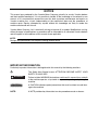
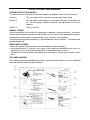
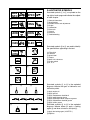
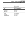
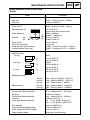
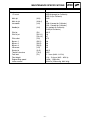
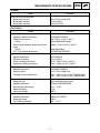
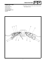
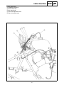
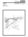
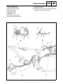
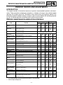
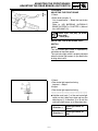
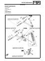
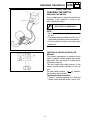
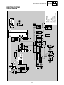
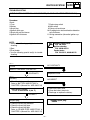
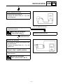
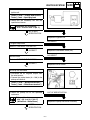
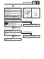
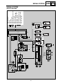
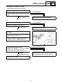
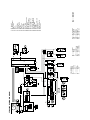
YFM350XP SUPPLEMENTARY SERVICE MANUAL LIT-11616-15-09 3GD-28197-16 FOREWORD This Supplementary Service Manual has been prepared to introduce new service and new data for the YFM350XP. For complete information on service procedures, it is necessary to use this Supplementary Service Manual together with the following manual. YFM350XA SERVICE MANUAL: 3GD-28197-12 YFM350XE SUPPLEMENTARY SERVICE MANUAL: 3GD-28197-13 YFM350XJ SUPPLEMENTARY SERVICE MANUAL: 3GD-28197-14 YFM350XKC (for California) SUPPLEMENTARY SERVICE MANUAL: 3GD-28197-15 YFM350XP SUPPLEMENTARY SERVICE MANUAL 2001 by Yamaha Motor Corporation, U.S.A. First Edition, May 2001 All rights reserved. Any reproduction or unauthorized use without the written permission of Yamaha Motor Corporation, U.S.A. is expressly prohibited. Printed in U.S.A. LIT-11616-15-09 EB001000 NOTICE This manual was produced by the Yamaha Motor Company primarily for use by Yamaha dealers and their qualified mechanics. It is not possible to include all the knowledge of a mechanic in one manual, so it is assumed that anyone who uses this book to perform maintenance and repairs on Yamaha machine has a basic understanding of the mechanical ideas and the procedures of machine repair. Repairs attempted by anyone without this knowledge are likely to render the machine unsafe and unfit for use. Yamaha Motor Company, Ltd. is continually striving to improve all its models. Modifications and significant changes in specifications or procedures will be forwarded to all authorized Yamaha dealers and will appear in future editions of this manual where applicable. NOTE: Designs and specifications are subject to change without notice. IMPORTANT INFORMATION Particularly important information is distinguished in this manual by the following notations. The Safety Alert Symbol means ATTENTION! BECOME ALERT! YOUR SAFETY IS INVOLVED! WARNING CAUTION: NOTE: Failure to follow WARNING instructions could result in severe injury or death to the machine operator, a bystander or a person inspecting or repairing the machine. A CAUTION indicates special precautions that must be taken to avoid damage to the machine. A NOTE provides key information to make procedures easier or clearer. HOW TO USE THIS MANUAL CONSTRUCTION OF THIS MANUAL This manual consists of chapters for the main categories of subjects. (See “Illustrated symbols”) 1st title 1: This is a chapter with its symbol on the upper right of each page. 2nd title 2: This title appears on the upper of each page on the left of the chapter symbol. (For the chapter “Periodic inspection and adjustment” the 3rd title appears.) 3rd title 3: This is a final title. MANUAL FORMAT All of the procedures in this manual are organized in a sequential, step-by-step format. The information has been compiled to provide the mechanic with an easy to read, handy reference that contains comprehensive explanations of all disassembly, repair, assembly, and inspections. A set of particularly important procedure 4 is placed between a line of asterisks “*” with each procedure preceded by “●”. IMPORTANT FEATURES ● Data and a special tool are framed in a box preceded by a relevant symbol 5. ● An encircled numeral 6 indicates a part name, and an encircled alphabetical letter data or an alignment mark 7, the others being indicated by an alphabetical letter in a box 8. ● A condition of a faulty component will precede an arrow symbol 9 and the course of action will follow it. EXPLODED DIAGRAM Each chapter provides exploded diagrams before each disassembly section for ease in identifying correct disassembly and assembly procedures. 1 EB003000 2 GEN INFO ILLUSTRATED SYMBOLS Illustrated symbols 1 to 9 are printed on the top right of each page and indicate the subject of each chapter. SPEC 3 4 CHK ADJ 1 General information 2 Specifications 3 Periodic checks and adjustments 4 Engine 5 Carburetion 6 Drive train 7 Chassis 8 Electrical 9 Troubleshooting ENG 5 6 CARB DRIV 7 8 CHAS – ELEC + 0 Illustrated symbols 0 to F are used to identify the specifications appearing in the text. A B 0 Filling fluid A Lubricant B Special tool C Torque D Wear limit, clearance E Engine speed F Ω, V, A C D 9 TRBL SHTG T. R. E F G H G E J K B M L M M LS N Illustrated symbols G to M in the exploded diagrams indicate the types of lubricants and lubrication points. I S O LT New G Apply engine oil H Apply gear oil I Apply molybdenum disulfide oil J Apply wheel bearing grease K Apply lightweight lithium soap base grease L Apply molybdenum disulfide grease M Apply silicon grease Illustrated symbols N to O in the exploded diagrams indicate where to apply a locking agent N and when to install a new part O. N Apply the locking agent (LOCTITE) O Replace CONTENTS SPECIFICATIONS ........................................................................................... 1 GENERAL SPECIFICATIONS ................................................................. 1 MAINTENANCE SPECIFICATIONS ........................................................ 2 ENGINE ................................................................................................ 2 CHASSIS .............................................................................................. 4 ELECTRICAL ....................................................................................... 4 CABLE ROUTING .................................................................................... 5 PERIODIC CHECKS AND ADJUSTMENTS ................................................... 9 INTRODUCTION ...................................................................................... 9 PERIODIC MAINTENANCE/LUBRICATION INTERVALS ....................... 9 CHASSIS ................................................................................................ 11 ADJUSTING THE FRONT BRAKE .................................................... 11 ADJUSTING THE REAR BRAKE LIGHT SWITCH ............................ 11 CHASSIS ....................................................................................................... 12 FRONT SUSPENSION ........................................................................... 12 ELECTRICAL ................................................................................................. 13 CHECKING THE SWITCH ..................................................................... 13 CHECKING THE SWITCH ................................................................. 13 CHECKING A SWITCH SHOWN IN THE MANUAL .......................... 13 IGNITION SYSTEM ................................................................................ 14 CIRCUIT DIAGRAM ........................................................................... 14 TROUBLESHOOTING ....................................................................... 15 SIGNAL SYSTEM ................................................................................... 20 CIRCUIT DIAGRAM ........................................................................... 20 CHECKING THE SIGNAL SYSTEM .................................................. 21 YFM350XP WIRING DIAGRAM GENERAL SPECIFICATIONS SPEC SPECIFICATIONS GENERAL SPECIFICATIONS Model Model code number: Spark plug: Type/manufacturer Gap Electrical: Ignition system Charging system Battery capacity Battery type Bulb wattage × quantity: Headlight Tail/brake light Neutral indicator light Reverse indicator light YFM350XP 5NF4 (except for California) 5NF5 (for California) DR8EA (NGK) 0.6 ~ 0.7 mm (0.024 ~ 0.028 in) DC. C.D.I. A.C. magneto 12 V 12AH GM12CZ-4A-2 12 V 30 W/30 W × 2 12 V 5 W/21 W × 1 12 V 3.4 W × 1 12 V 3.4 W × 1 –1– MAINTENANCE SPECIFICATIONS SPEC MAINTENANCE SPECIFICATIONS ENGINE Model YFM350XP Cylinder: Bore size Taper limit Piston: Piston size “D” Measuring point “H” 82.97 ~ 83.02 mm (3.267 ~ 3.269 in) <0.05 mm (0.002 in)> Piston clearance Oversize H 2nd 4th D Piston off-set Piston off-set direction Inside diameter (piston pin bore) Outside diameter (piston pin) Piston ring: Sectional sketch Top ring: B T 2nd ring: B T Oil ring: B 82.92 ~ 82.97 mm (3.265 ~ 3.267 in) 5.5 mm (0.22 in) (From bottom line of piston skirts) 0.040 ~ 0.060 mm (0.00157 ~ 0.00236 in) 83.5 mm (3.287 in) 84.0 mm (3.307 in) 0.5 mm (0.02 in) Intake side 19.004 ~ 19.015 mm (0.7481 ~ 0.7486 in) 18.991 ~ 19.000 mm (0.7477 ~ 0.7480 in) B T B T Barrel 1.2 mm (0.047 in) 3.3 mm (0.130 in) Tapper 1.5 mm (0.059 in) 3.4 mm (0.134 in) 2.8 mm (0.110 in) 2.8 mm (0.110 in) Top ring 2nd ring Oil ring Top ring 2nd ring 0.20 ~ 0.40 mm (0.00787 ~ 0.0157 in) 0.20 ~ 0.40 mm (0.00787 ~ 0.0157 in) 0.30 ~ 0.90 mm (0.012 ~ 0.035 in) 0.03 ~ 0.09 mm (0.0012 ~ 0.0035 in) 0.03 ~ 0.07 mm (0.0012 ~ 0.0028 in) B T T End gap (installed) Side clearance Clutch: Friction plate thickness/quantity Warp limit Friction plate thickness/quantity Warp limit Clutch plate thickness/quantity Max. warpage Clutch spring free length/quantity Clutch spring minimum free length Clutch release method 2.74 ~ 2.86 mm (0.107 ~ 0.113 in)/6 <2.64 mm (0.104 in)> 2.94 ~ 3.06 mm (0.116 ~ 0.120 in)/1 <2.84 mm (0.112 in)> 1.5 ~ 1.7 mm (0.059 ~ 0.066 in)/4 1.9 ~ 2.1 mm (0.0748 ~ 0.0827 in)/2 <0.2 mm (0.00787 in)> 47.8 mm (1.882 in)/5 46.5 mm (1.831 in) Outer push (rack and pinon) –2– MAINTENANCE SPECIFICATIONS Model YFM350XP Carburetor: I. D. mark Main jet Main air jet Jet needle (M.J) (M.A.J) (J.N) Needle jet (N.J) Pilot jet Pilot air jet (P.J) (P.A.J.1) (P.A.J.2) (P.O) (B.P.1) (B.P.2) (B.P.3) (V.S) (G.S.) (Th.V) (F.L) Pilot outlet Bypass 1 Bypass 2 Bypass 3 Valve seat Starter jet Throttle valve size Fuel level Float height Engine idling speed Intake vacuum SPEC 3GD 00 (except for California) 3GD 10 (for California) #145 0.6 5J18-3 (except for California) 5J31-1 (except for California) O-6 (except for California) O-6M (for California) #42.5 1.0 0.7 0.75 0.8 0.8 0.8 2.5 #62.5 #125 2 ~ 3 mm (0.08 ~ 0.12 in) 11.4 ~ 13.4 mm (0.45 ~ 0.53 in) 1,450 ~ 1,550 r/min 33.3 kPa (250 mmHg, 9.83 inHg) –3– MAINTENANCE SPECIFICATIONS SPEC CHASSIS Model Brake lever and brake pedal: Brake lever free play Brake pedal position Brake pedal free play YFM350XP 0 mm (0 in) at lever end 10 mm (0.4 in) 8 mm (0.315 in) ELECTRICAL Model C.D.I.: Magneto model/manufacturer Pickup coil resistance (Color) Rotor rotation direction detection coil resistance (Color) C.D.I. unit-model/manufacturer Ignition coil: Model/manufacturer Minimum spark gap Primary winding resistance Secondary winding resistance Charging system: Model/manufacturer Nominal output Charging coil resistance/color Rectifier/regulator: Regulator type Model/manufacturer No load regulated voltage Rectifier capacity Withstand voltage Starter relay: Model/manufacturer Amperage rating Coil winding resistance YFM350XP F4T466/MITSUBISHI 459 ~ 561 Ω at 20 °C (68 °F) (White/Red-White/Green) 0.083 ~ 0.101 Ω at 20 °C (68 °F) (Red-White/Blue) F8T38675/MITSUBISHI 2JN/YAMAHA 6 mm (0.24 in) 0.18 ~ 0.28 Ω at 20 °C (68 °F) 6.32 ~ 9.48 kΩ at 20 °C (68 °F) F4T466/MITSUBISHI 14 V 15 A at 5,000 r/min 0.51 ~ 0.63 Ω at 20 °C (68 °F)/White-White 0.47 ~ 0.57 Ω at 20 °C (68 °F)/White-White Semi conductor-short circuit SH640-11/SHINDENGEN 14.1 ~ 14.9 V 14 A 200 V MS5D-611/JIDECO 100 A 3.9 ~ 4.7 Ω –4– CABLE ROUTING SPEC CABLE ROUTING 1 Clutch switch 2 Rear brake cable 3 Clutch cable 4 Front brake hose 5 Front brake light switch 6 Throttle cable 7 Band È Install the fuel tank breather hose into the hole of the handlebar cover. –5– CABLE ROUTING 1 Main switch lead 2 Handlebar switch lead 3 Clutch switch lead 4 Park switch lead 5 Front brake light switch lead 6 Fuel tank breather hose –6– SPEC CABLE ROUTING 1 Starter relay 2 Neutral relay 3 Tail/brake light 4 CDI unit 5 Rectifier/regulator 6 Fuse 7 Battery breather hose SPEC È Pass the battery breather hose through the inside of the frame bracket. É Pass the battery breather hose through the guide. –7 – CABLE ROUTING 1 Battery negative lead 2 Rear brake light switch 3 Drive select lever switch 4 Rear brake cable 5 Rear brake hose 6 Rectifier/regulator 7 CDI unit 8 Carburetor overflow hose 9 Rear brake light switch lead SPEC È Pass the wire harness and starter motor lead through the holder. É Fasten the wire harness, starter motor lead and handlebar switch lead with the band. –8– INTRODUCTION/ PERIODIC MAINTENANCE/LUBRICATION INTERVALS CHK ADJ EB300000 PERIODIC CHECKS AND ADJUSTMENTS INTRODUCTION This chapter includes all information necessary to perform recommended inspections and adjustments. These preventive maintenance procedures, if followed, will ensure more reliable vehicle operation and a longer service life. The need for costly overhaul work will be greatly reduced. This information applies to vehicles already in service as well as to new vehicles that are being prepared for sale. All service technicians should be familiar with this entire chapter. EB301000 PERIODIC MAINTENANCE/LUBRICATION INTERVALS INITIAL ITEM ROUTINE 1 month Valves* • Check valve clearance. • Adjust if necessary. Spark plug • Check condition. • Adjust gap and clean. • Replace if necessary. Air filter • Clean. • Replace if necessary. Carburetor* • Check idle speed/starter operation. • Adjust if necessary. Crankcase breather system* • Check breather hose for cracks or damage. • Replace if necessary. Exhaust system* • Check for leakage. • Tighten if necessary. • Replace gasket(s) if necessary. Spark arrester • Clean. Fuel line* • Check fuel hose for cracks or damage. • Replace if necessary. Engine oil • Replace (Warm engine before draining). Engine oil filter element • Clean. • Replace if necessary. Engine oil strainer • Clean. Drive chain • Check and adjust slack/alignment/clean/lube. Brake* • Check operation/fluid leakage/See NOTE Page 10. • Correct if necessary. Clutch* • Check operation. • Adjust if necessary. Wheels* • Check balance/damage/runout. • Replace if necessary. Wheel bearings* • Check bearing assembly for looseness/damage. • Replace if damaged. Steering system* • • • • 3 months EVERY 6 months 6 months Every 20~40 hours (More often in wet or dusty areas.) Check operation. Repair if damaged. Check toe-in. Adjust if necessary. Upper and lower arm • Lubricate every 6 months.** pivot and steering shaft* Rear arm pivot* • Lubricate every 6 months.** Fittings and Fasteners* • Check all chassis fittings and fasteners. • Correct if necessary. Battery* • Check specific gravity. • Check breather pipe for proper routing. • Correct if necessary. * It is recommended that these items be serviced by a Yamaha dealer. ** Lithium-soap-based grease –9– 1 year PERIODIC MAINTENANCE/LUBRICATION INTERVALS CHK ADJ NOTE: ● Recommended brake fluid: DOT4 ● Brake fluid replacement: 1.When disassembling the master cylinder or caliper, replace the brake fluid. Normally check the brake fluid level and add fluid as required. 2.On the inner parts of the master cylinder and caliper, replace the oil seals every two years. 3.Replace the brake hoses every four years, or if cracked or damaged. – 10 – ADJUSTING THE FRONT BRAKE/ ADJUSTING THE REAR BRAKE LIGHT SWITCH CHK ADJ CHASSIS ADJUSTING THE FRONT BRAKE 1.Check: ● Brake lever free play a Out of specification → Bleed the front brake system. Refer to “AIR BLEEDING (HYDRAULIC BRAKE SYSTEM)” in CHAPTER 3. (Manual No.: 3GD-28197-12) Brake lever free play (at brake lever end): 0 mm (0 in) ADJUSTING THE REAR BRAKE LIGHT SWITCH NOTE: The rear brake light switch is operated by movement of the brake pedal. The rear brake light switch is properly adjusted when the brake light comes on just before the braking effect starts. 1.Check: ● Rear brake light operation timing Incorrect → Adjust. 2.Adjust: ● Rear brake light operation timing *********************************************** the main body 1 of the rear brake light switch so that it does not rotate and turn the adjusting nut 2 in direction a or b until the rear brake light comes on at the proper time. ● Hold Direction a Brake light comes on sooner. Direction b Brake light comes on later. *********************************************** – 11 – FRONT SUSPENSION CHASSIS FRONT SUSPENSION 1 Thrust cover 2 Bushing 3 Front upper arm 4 Collar 5 Front lower arm 6 Shock absorber 7 Steering knuckle – 12 – CHAS CHECKING THE SWITCH ELEC – + ELECTRICAL CHECKING THE SWITCH CHECKING THE SWITCH Use a pocket tester to check the terminals for continuity. If the continuity is faulty at any point, replace the switch. Pocket tester: P/N. YU-03112, 90890-03112 NOTE: ● Set the pocket tester to “0” before starting the test. ● The pocket tester should be set to the “Ω × 1” range when testing the switch for continuity. ● Turn the switch on and off a few times when checking it. CHECKING A SWITCH SHOWN IN THE MANUAL The terminal connections for switches (main switch, handlebar switch, engine stop switch, light switch, etc.) are shown in a chart similar to the one on the left. This chart shows the switch positions in the column and the switch lead colors in the top row. For each switch position, “ ” indicates the terminals with continuity. The example chart shows that: 1 There is continuity between the “Red and Brown” leads when the switch is set to “ON”. – 13 – W W W W W W B W W W W R W/G W W W W – 14 – B G B Y G L Y R/B Br R/W R/B M R G B Y OFF LO HI N ON OFF 3 W/R W/G W/G R W/G Br R/W Br 4 R/B R/W R R B L/W 6 L/W Br R/B L/W O B Y L Br Br R B L G Y G B Y G G OFF ON O B Y (GRAY) (GRAY) R Y B G L G B Y B K B 7 R/W 5 OFF PUSH P B B B R R R/W B L Y Y Br B B J R/W Br (BLACK) Y (BLACK) R/W R/W L/W Y B Br (BLACK) Y (BLACK) B I B W/B B/Y G/Y G/W 8 B/Y G/W W/B R/B L/W R W/R W/G G/L Br H G W/G W/G R W/R R W/R R/W Br L (GRAY) R B W (GRAY) B W R W/L W/R R 2 W W 1 F B 9 Sb Br E G/Y O B Sb B Br W/B G/W Sb B B G/Y C B B A G/Y 0 G/W G/W 1 AC magneto 3 Main switch D 4 Fuse 5 Battery 9 CDI unit 0 Ignition coil A Spark plug O Engine stop switch G/W (GREEN) Sb G/W W/B Br O IGNITION SYSTEM ELEC – + EB802000 IGNITION SYSTEM CIRCUIT DIAGRAM IGNITION SYSTEM ELEC – + EB802010 TROUBLESHOOTING IF THE IGNITION SYSTEM FAILS TO OPERATE (NO SPARK OR INTERMITTENT SPARK): Procedure Check: 1.Fuse 2.Battery 3.Spark plug 4.Ignition spark gap 5.Spark plug cap resistance 6.Ignition coil resistance 7.Engine stop switch 8.Main switch 9.Pickup coil resistance 10.Charging/rotor rotation direction detection coil resistance 11.Wiring connection (the entire ignition system) NOTE: ● Remove the following part(s) before troubleshooting: 1)Seat 2)Front fender ● Use the following special tool(s) for troubleshooting. Dynamic spark tester: P/N. YM-34487 Ignition checker: P/N. 90890-06754 Pocket tester: P/N. YU-03112, 90890-03112 EB802011 NO CONTINUITY 1.Fuse Refer to “CHECKING THE SWITCH”. CONTINUITY Replace the fuse. EB802012 2.Battery ● INCORRECT Check the battery condition. Refer to “BATTERY INSPECTION” in CHAPTER 3. (Manual No.: 3GD-28197-12) ● Open-circuit voltage: 12.8 V or more at 20 °C (68 °F) ● ● Refill with battery fluid. Clean the battery terminals. Recharge or replace the battery. CORRECT 3.Spark plug ● ● ● Standard spark plug: DR8EA Check the spark plug condition. Check the spark plug type. Check the spark plug gap. Refer to “SPARK PLUG INSPECTION” in CHAPTER 3. (Manual No.: 3GD-28197-12) –15 – IGNITION SYSTEM ELEC INCORRECT Spark plug gap: 0.8 ~ 0.9 mm (0.031 ~ 0.035 in) CORRECT Repair or replace the spark plug. For USA and CDN 4.Ignition spark gap ● ● Disconnect the spark plug cap from the spark plug. Connect the dynamic spark tester 1 as shown. 2 Spark plug cap 3 Spark plug ● ● ● Turn the main switch to “ON”. Check the ignition spark gap. Crank the engine by pushing the starter switch, and increase the spark gap until a misfiring occurs. MEETS SPECIFICATION Minimum spark gap: 6.0 mm (0.24 in) The ignition system is not faulty. For Europe and Oceania 4.Ignition spark gap ● ● Disconnect the spark plug cap from the spark plug. Connect the dynamic spark tester 1 as shown. 2 Spark plug cap ● ● ● Turn the main switch to “ON”. Check the ignition spark gap a. Crank the engine by pushing the starter switch, and increase the spark gap until a misfiring occurs. MEETS SPECIFICATION Minimum spark gap: 6.0 mm (0.24 in) The ignition system is not faulty. * OUT OF SPECIFICATION OR NO SPARK – 16 – – + IGNITION SYSTEM ELEC * 5.Spark plug cap resistance ● ● ● Remove the spark plug cap. Connect the pocket tester (Ω × 1k) to the spark plug cap. OUT OF SPECIFICATION Check that the spark plug cap has the specified resistance. Spark plug cap resistance: 10 kΩ at 20 °C (68 °F) Replace the spark plug cap. MEETS SPECIFICATION 6.Ignition coil resistance ● ● Disconnect the ignition coil connector from the wire harness. Connect the pocket tester (Ω × 1) to the ignition coil. Tester (+) lead → Orange lead terminal Tester (–) lead → Ignition coil base ● Check that the primary coil has the specified resistance. Primary coil resistance: 0.18 ~ 0.28 Ω at 20 °C (68 °F) – 17 – – + IGNITION SYSTEM ● ELEC – Connect the pocket tester (Ω × 1k) to the ignition coil. Tester (+) lead → Orange lead terminal Tester (–) lead → Spark plug lead ● Check that the secondary coil has the specified resistance. Secondary coil resistance: 6.32 ~ 9.48 kΩ at 20 °C (68 °F) BOTH MEET SPECIFICATION Replace the ignition coil. INCORRECT 7.Engine stop switch Refer to “CHECKING THE SWITCH”. CORRECT Replace the handlebar switch (left). INCORRECT 8.Main switch Refer to “CHECKING THE SWITCH”. CORRECT Replace the main switch. 9.Pickup coil resistance ● ● Disconnect the AC magneto coupler from the wire harness. Connect the pocket tester (Ω × 100) to the pickup coil terminal. Tester (+) lead → White/Red terminal 1 Tester (–) lead → White/Green terminal 2 ● Check the pickup coil for the specified resistance. OUT OF SPECIFICATION Pickup coil resistance: 459 ~ 561 Ω at 20 °C (68 °F) (White/Red – White/Green) Replace the pickup coil/starter assembly. MEETS SPECIFICATION * – 18 – + IGNITION SYSTEM * ELEC – C0NTINUITY 10.Charging/rotor rotation direction detection coil resistance ● ● Disconnect the AC magneto coupler from the wire harness. Connect the pocket tester (Ω × 100) to the charging/rotor rotation direction detection coil terminal. Tester (+) lead → Red terminal 1 Tester (–) lead → White/Blue terminal 2 ● Check the charging/rotor rotation direction detection coil for the specified resistance. OUT OF SPECIFICATION Rotor rotation direction detection coil resistance: 0.083 ~ 0.101 Ω at 20 °C (68 °F) (Red – White/Blue) Replace the pickup coil/stator assembly. MEETS SPECIFICATION 11.Wiring connection ● POOR CONNECTION Check the connections of the entire ignition system. Refer to “CIRCUIT DIAGRAM”. Properly connect the ignition system. CORRECT Replace the CDI unit. – 19 – + W W W W W W B W W W W W W W W – 20 – B G B Y G L Y R/B Br R/W R/B M R G B Y OFF LO HI N ON OFF 3 W/R W/G W/G R W/G Br R/W Br 4 R/B R/W R R B L/W 6 L/W Br R/B L/W O B Y L Br Br R B L G Y G B Y G G OFF ON O B Y (GRAY) (GRAY) R Y B G L G B Y B K B 7 R/W 5 OFF PUSH P B B B R R R/W B L Y Y Br B B J R/W Br (BLACK) Y (BLACK) R/W R/W L/W B Br (BLACK) Y (BLACK) B I B W/B B/Y G/Y G/W 8 B/Y G/W W/B R/B L/W R W/R W/G G/L Br H G W/R W/G W/R R W/G R/W Br L (GRAY) R B W (GRAY) B W R W/L W/R R W/G R 2 W W 1 R F B 9 Sb Br E G/Y O B Sb B Br W/B G/W Sb B G/Y C D B G/W G/W G/W (GREEN) Sb G/W W/B Br O G/Y B 3 Main switch 4 Fuse 0 5 Battery A C Neutral relay D Drive select lever switch E Neutral switch F Neutral indicator light G Reverse indicator light B H Reverse switch I Rear brake light switch J Front brake light switch K Tail/brake light SIGNAL SYSTEM ELEC – + EB806000 SIGNAL SYSTEM CIRCUIT DIAGRAM SIGNAL SYSTEM ELEC – + CHECKING THE SIGNAL SYSTEM 1.If the tail/brake light fails to come on: 1.Bulb and bulb socket ● NO CONTINUITY Check the bulb and bulb socket for continuity. CONTINUITY Replace the bulb and/or bulb socket. NO CONTINUITY 2.Brake light switches Refer to “CHECKING THE SWITCH”. CONTINUITY Replace the brake switch. 3.Voltage ● Connect the pocket tester (DC 20V) to the bulb socket connector. Tester (+) lead → Yellow terminal 1 Tester (–) lead → Black terminal 2 ● ● OUT OF SPECIFICATION Turn the main switch to “ON”. Check the voltage (12 V) of the “Yellow” lead on the bulb socket connector. The wiring circuit from the main switch to the bulb socket connector is faulty, repair it. MEETS SPECIFICATION This circuit is not faulty. – 21 – YAMAHA MOTOR CO., LTD. 2500 SHINGAI IWATA SHIZUOKA JAPAN PRINTED IN U.S.A. W W W W W W B W W W W R W/G W W B G B Y G L Y R/B M G B Y OFF LO HI N ON OFF 3 W/R W/G W/G R Br R/W R/B R Br R/W Br 4 R/B R/W R R B L/W 6 L/W Br R/B L/W O B Y L Br Br R B L G Y G B Y G G OFF ON O B Y (GRAY) (GRAY) R Y B G L G B Y B K B 7 R/W 5 OFF PUSH P B B B R R R/W B L Y Y Br B B J R/W Br Y B Br (BLACK) Y (BLACK) B I B 8 B/Y G/W W/B R/B L/W G/L Br H G COLOR CODE B ............Black Br ...........Brown G............Green L.............Blue O............Orange R ............Red (BLACK) Y (BLACK) R/W R/W L/W W/B B/Y G/Y G/W R W/R W/G W/R W/G W/G W/R R W/G R/W Br L (GRAY) R B W (GRAY) B W R W R W/L W/R W 2 W W 1 R YFM350XP WIRING DIAGRAM F B 9 Sb Br B Sb B Br W/B G/W Sb B B G/Y C D B G/W G/W G/W (GREEN) Sb G/W W/B Br O B A G/Y 0 Sb ..........Sky blue W ...........White Y ............Yellow B/Y.........Black/Yellow G/L.........Green/Blue G/W .......Green/White E G/Y O W/L ....... White/Blue W/R ....... White/Red AC magneto Rectifier/regulator Main switch Fuse Battery Starter relay Starter motor Clutch switch CDI unit Ignition coil Spark plug Park switch Neutral relay Drive select lever switch Neutral switch Neutral indicator light Reverse indicator light Reverse switch Rear brake light switch Front brake light switch Tail/brake light Headlight Handlebar switch (left) Lights switch Engine stop switch Start switch G/Y.........Green/Yellow L/W ........Blue/White R/B.........Red/Black R/W........Red/White W/B ........White/Black W/G........White/Green 1 2 3 4 5 6 7 8 9 0 A B C D E F G H I J K L M N O P