1
Fire Alarm
Control/Communicator
User's Manual
5110XM
N8028 4/96
TABLE OF CONTENTS
SYSTEM OVERVIEW .................................................3
General...................................................................3
Zones.....................................................................3
Fire & Emergency Protection....................................4
Alarms.....................................................................4
Memory of Alarm......................................................4
ABOUT THE BUILT-IN INDICATORS............................5
ABOUT THE OPTIONAL KEYPADS ............................7
General...................................................................7
Keypad Displays......................................................7
FUNCTIONS OF THE REMOTE KEYPAD.....................8
FIXED-WORD KEYPAD DISPLAYS..............................9
REMOTE KEYPAD USER CODES ............................10
General.................................................................10
To Assign, Change, or Delete User Codes ..............10
REMOTE KEYPAD EMERGENCY KEYS....................11
Using Emergency Keys..........................................11
Emergency Key Programmed Functions.................12
NORMAL STANDBY OPERATION.............................13
FIRE ALARM PROTECTION......................................14
General.................................................................14
In case of Fire ........................................................14
Silencing and Resetting a Fire Alarm .......................15
EMERGENCY ALARMS ............................................16
General.................................................................16
Silencing and Resetting an Emergency Alarm..........16
BYPASSING PROTECTION ZONES..........................17
SUPERVISORY CONDITIONS...................................18
General.................................................................18
Silencing and Resetting a Supervisory Indication .....18
TROUBLE CONDITIONS...........................................19
ACTIVATING A FIRE DRILL TEST..............................21
QUICK GUIDE TO SYSTEM FUNCTIONS ...................22
SUMMARY OF AUDIBLE/VISUAL NOTIFICATION ......23
PROTECTION ZONES LIST......................................24
FCC STATEMENTS..................................................25
LIMITATIONS STATEMENT ......................................27
SERVICING INFORMATION.......................................28
WARRANTY............................................... Back Cover
This manual is a step-by-step guide that will acquaint you with the system's features and benefits. It defines the
components and their functions, describes their operation, and instructs you with normal and emergency
procedures.
Keep this manual in a convenient place so that you can refer to it as necessary.
–2–
SYSTEM OVERVIEW
General
Congratulations on your ownership of an Ademco Alarm System. You've made a
wise decision in choosing it, for it represents the latest in alarm protection
technology today, including microcomputer technology to monitor all system status.
Ademco is the world's largest manufacturer of alarm systems and millions of
premises are protected by Ademco systems.
Your system is a UL Listed commercial fire alarm control/communicator. It monitors,
on an around-the clock basis, the various fire alarm warning, emergency alarm
warning and fire sprinkler system supervisory sensors that have been installed in
your system. When the control detects an alarm, supervisory, or trouble condition,
it automatically triggers an on-premises warning indication and transmits a message
to a central station over the telephone line so that appropriate action can be taken.
The control features a built-in warning buzzer and LED indicators which provide
the on-premises warning indication. In addition, your system may include an
optional remote keypad and/or optional external alarm warning sounders which will
provide additional on-premises warning indications. Please disregard references to
these devices in the text that follows, if they were not installed in your system.
Zones
Your system has five protection zones. Your installer has assigned each of your
system's sensing devices to one of these zones. For example, warehouse smoke
detectors may have been assigned to zone 01, a fire sprinkler water valve
supervisory switch may have been assigned to zone 02, etc.. If a remote keypad
was installed in your system, it will display these zone numbers when an alarm,
supervisory or trouble condition is detected, so that the nature and location of the
fault can be pinpointed..
–3–
SYSTEM OVERVIEW
Fire & Emergency
Protection
The fire and emergency protection portions of your system are always on and will
sound an alarm if an alarm condition is detected.
Alarms
When an alarm occurs, the control's buzzer, the keypad and external sounders will
sound, and a message at the keypad will identify the zone(s) causing the alarm. In
addition, an alarm message will be sent to the connected central monitoring station.
You may stop the sound by pressing the SILENCE/RESET button at the control,
or by entering the OFF sequence (user code + OFF key) at your keypad .
Memory Of Alarm
When an alarm, supervisory or trouble condition occurs, the keypad displays the
number(s) of the zone(s) that caused the problem, and displays the type of
condition present (ex. Fire, Alarm, Supv., Check). The display remains until it is
cleared by entering the OFF sequence (user code + OFF key) a second time or
by pressing the SILENCE/RESET button a second time if no keypad is present.
–4–
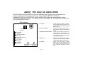
ABOUT THE BUILT-IN INDICATORS
The LED indicators, SILENCE/RESET button and WARNING buzzer (shown below) are located on the
control's main board inside the control's enclosure. The AC POWER, BATTERY TROUBLE,
COMMUNICATION FAIL, LINE DEFAULT and SILENCED LED indicators are visible through a viewing
window on the door of the enclosure. The enclosure door must be opened with the supplied key to gain access
to the SILENCE/RESET button.
LED Indicators
AC POWER .............................Lights when AC power is present.
Turns off when AC power is low or not
present and system is operating from
battery power.
SILENCE/RESET
BUTTON
BUZZER
COMMUNICATION FAILURE.......Lights when attempts to transmit a
message to the central station have
failed. Remains unlit when there are
no problems with central station
message transmission.
AC POWER
(GREEN)
BATTERY TROUBLE
(YELLOW)
COMMUNICATION FAIL
(YELLOW)
LINE FAULT ............................Lights when either the main or backup phone lines are faulted. Remains
unlit when both phone lines are okay.
LINE FAULT
(YELLOW)
SILENCED
(YELLOW)
BACKUP DIALER
LINE SEIZE
BATTERY TROUBLE .................Lights when battery power is low or
disconnected. Turns off when battery
is OK.
MAIN DIALER
LINE SEIZE
SILENCED ..............................Lights when the built-in warning
buzzer, the remote keypad buzzer
and external alarm sounders have
been silenced. Otherwise remains
unlit.
–5–
Warning Buzzer
Silence/Reset Button
Main Dialer Line Seize
Backup Dialer LIne Seize
Produces slow on/off pulsing sound for fire alarms, steady sound for
emergency alarms, and rapid on/off pulsing sound for supervisory and
trouble conditions.
Press to silence the built-in warning buzzer, the remote keypad warning
buzzer and the external alarm sounder. A second press resets faulted smoke
detectors and resets LED indicators if associated fault conditions have been
corrected.
Lights when control is transmitting a message to the central station on the
main phone line.
Lights when control is transmitting a message to the central station on the
backup phone line.
–6–
ABOUT THE OPTIONAL KEYPADS
General
The keypads feature a telephone style (digital) keypad and a Liquid Crystal
Display (LCD) which shows the nature and location of all occurrences.
The keypads feature a built-in sounder which emits the same alarm sounds as the
control's built-in warning buzzer during alarm conditions.
The keypad's display screen displays the same indications as the control's built-in
LED indicators, and in addition, displays the zone number of faulted zones as well
as the type of fault (i.e. alarm, supervisory or trouble) present. The telephone
style keypad keys allow entry of commands for silencing the warning sounds,
resetting faulted smoke detectors, activating various system tests, etc.
Keypad Displays
There are two basic types of keypad displays, Alpha and Fixed-Word, either of
which may have been used in your system.
• Alpha Keypad Displays feature a 2-line, 32 character alphanumeric Liquid
Crystal Display (LCD) which can display the nature and location of all
occurrences in friendly English.
• Fixed-Word Keypad Displays are functionally similar to the Alpha Keypads,
except that their LCD display uses pre-designated (fixed) words to identify the
nature and location of occurrences.
Unless stated otherwise, all commands and procedures described herein apply
equally to all keypads.
ARMED
READY
OFF
ARMED
Alpha
Keypad
READY
A
OFF
OFF
AWAY
AWAY
STAY
1
2
3
3
B
MAX
MAX
TEST
TEST
BYPASS
4
5
5
6
6
C
INSTANT
INSTANT
CODE
CHIME
CHIME
7
7
8
9
9
0
0
#
#
D
A
B
Fixed-Word
Keypad
READY
READY
*
*
PANIC
–7–
C
AWAY
STAY
1
2
3
MAX
TEST
BYPASS
4
5
6
INSTANT
CODE
CHIME
7
8
9
0
#
READY
*
PANIC
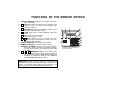
FUNCTIONS OF THE REMOTE KEYPAD
1.
DISPLAY WINDOW: Displays zone number and system
status messages.
2.
1 OFF Key: Silences audible alarm, supervisory and
trouble sounds, and clears visual display after
problem's correction.
3.
6 BYPASS Key: Removes individual protection zones
from being monitored by the system.
4.
8 CODE Key: Used to assign additional 4-digit user
codes.
5.
# Key: Used to activate fire drill.
(enter user 2's code + # + 69)
6.
0 – 9 Keys: Used to enter your 4-digit user code,
which must be entered before pressing the OFF,
BYPASS, CODE or [#] keys.
7. READY INDICATOR: Not used with this system.
8. ARMED INDICATOR: Not used with this system.
9. INTERNAL SOUNDER: Sound is: slow on/off pulsing for
fire alarms, steady dual-tone for emergency alarms,
and rapid on/off pulsing for supervisory and trouble
conditions.
10. A , B , C EMERGENCY Keys: Your installer may
have programmed these keys for manual activation of
fire or emergency alarms. Note: Other keys may be
available for emergency functions (see REMOTE
KEYPAD EMERGENCY KEYS section).
IMPORTANT!: When entering codes and commands, sequential key depressions must be made within 2 seconds of one
another. If 2 seconds elapses without a key depression, the
entry is aborted and must be repeated from its beginning.
–8–
8
7
10
1
2
3
ARMED
READY
A
OFF
AWAY
STAY
1
2
3
TEST
BYPASS
B
MAX
4
5
6
C
INSTANT
CODE
CHIME
7
8
9
D
READY
0
#
9
*
4
5
PANIC
6
TYPICAL ALPHA KEYPAD
Fixed-Word Keypads are functionally similar,
except for screen displays.
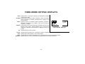
FIXED-WORD KEYPAD DISPLAYS
F I R E Appears when a fire alarm is detected. Accompanied by a display
of the zone # in alarm.
ALARM Appears when any type of alarm is detected. "FIRE" also appears
when a fire alarm is detected. Accompanied by a display of the
zone # in alarm.
S U P V Appears when a fire sprinkler system supervisory condition is
detected. Accompanied by a display of the zone # having the
supervisory condition.
CHECK Appears when a fire zone wiring fault is detected at any time. Also
appears when certain system problems such as phone line
problems are detected. Accompanied by a display of the zone # in
trouble.
A C Appears when AC power is present.
NO AC
BAT
TEST
BYPASS
AWAY
BYPASS
STAY
ALARM
FIRE CHECK
INSTANT
FIXED-WORD DISPLAY
Appears when AC power is low, or not present. System is operating from backup battery power.
Appears when backup battery is low or disconnected.
Appears when the system is operating in one of its test modes (such as the fire drill test mode).
Appears when one or more zones have been bypassed and are no longer operational.
–9–
SUPV NO AC
TEST
NOT READY
CHIME BAT
REMOTE KEYPAD USER CODES
General
If your system has a remote keypad installed, your installer will have programmed
a 4-digit user code (known as User Number 2 code) that can be entered at your
keypad to silence/reset alarms, bypass protection zones and activate the fire drill
test. This code may also be used to assign up to four other user codes (known as
User Number 3–6 codes).
The User Number 3–6 codes are intended for users who need limited and/or
temporary control over system operation. These codes can perform the same
functions as the User Number 2 code except for assigning user codes and
activating the fire drill test.
To Assign, Change, or
Delete
User Codes
User Number 2 can change, but not delete, his/her own code and can assign,
change, or delete codes for User Numbers 3–6.
User Numbers 3–6 cannot assign, change, or delete user codes.
1. Enter the User Number 2 code and press the CODE key.
2. Enter a single-digit User Number (2–6) for the user whose code is to be
assigned, changed, or deleted.
3. If assigning or changing a user's code, enter the new 4-digit code for that
user. The keypad will beep once, indicating that the new code has been
accepted.
If deleting a user's code, perform steps 1 and 2 and then stop. After a few
moments the keypad will beep once, indicating that the existing code has been
deleted.
–10–
REMOTE KEYPAD EMERGENCY KEYS
Using
Emergency Keys
(for manually activating
silent and/or
audible alarms)
Your installer may have programmed the keypad's A, B, or C keys to allow manual
activation of fire and/or emergency alarms. The functions that might be programmed
are: Fire, Silent Emergency, Audible Emergency, and Personal Emergency.
A fire alarm sends a fire alarm message to the central station and uniquely
sounds at the control and at keypad(s) and external bells and sirens. A FIRE
message plus a zone number (see table on next page) is also displayed on the
keypad.
A silent emergency sends a silent alarm signal to the central station, but there is
no audible alarm or visual display.
An audible emergency sends a signal to the central station and sounds a loud,
steady alarm at the control and at your keypad(s) and at any external sounders
that may be connected. An ALARM message plus a zone number (see table on
next page) is also displayed on the keypad.
A personal emergency alarm sends an emergency message to the central
station and sounds at the control and at keypad(s), but not at external bells or
sirens. An ALARM message plus a zone number (see table on next page) is also
displayed on the keypad.
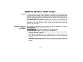
TO MANUALLY ACTIVATE A FUNCTION AT ANY TIME OF DAY OR NIGHT
(SEE TABLE AND DIAGRAM ON NEXT PAGE)
Press the programmed A , B , or C emergency key for at least two seconds,
or alternatively,
Press both keys of the corresponding 1 & * (A), ∗ & # (B), or 3 & # (C) emergency key
pair at the same time.
–11–
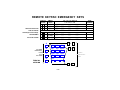
REMOTE KEYPAD EMERGENCY KEYS
CHECK IF
ACTIVE
EMERG.
KEY(S)
P R O G R A M M E D
F U N C T I O N
ZONE
NUMBER
[A]
____FIRE, ____SILENT, ____AUDIBLE, ____PERSONAL
95
[B]
____FIRE, ____SILENT, ____AUDIBLE, ____PERSONAL
07
SEE YOUR INSTALLER
[C]
____FIRE, ____SILENT, ____AUDIBLE, ____PERSONAL
96
AND NOTE HERE
OR
THE KEY(S) & FUNCTION(S)
[1] & [∗]
____FIRE, ____SILENT, ____AUDIBLE, ____PERSONAL
95
PROGRAMMED
[∗] & [#]
____FIRE, ____SILENT, ____AUDIBLE, ____PERSONAL
07
FOR YOUR SYSTEM
[3] & [#]
____FIRE, ____SILENT, ____AUDIBLE, ____PERSONAL
96
• KEY [D] ON YOUR KEYPAD IS NOT ACTIVE HERE.
A
LETTERED
EMERGENCY
KEYS
("D" IS
NOT USED)
<
B
C
AWAY
STAY
1
2
3
MAX
TEST
BYPASS
4
5
6
INSTANT CODE
7
D
TYPICAL
KEYPAD
OFF
1 & *
3 &#
PAIRED
CHIME
8
9
0
#
> EMERGENCY
KEYS
READY
*
EMER
–12–
* & #
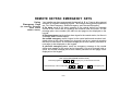
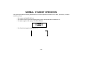
NORMAL STANDBY OPERATION
Your system provides the following indications when in normal operation and there are no alarm, supervisory, or trouble
conditions present:
• The control's AC POWER LED is lit.
• The control's built-in buzzer and keypad warning buzzer and external alarm sounders are off.
• The Alpha keypad's LCD displays "SYSTEM NORMAL".
**** SYSTEM ****
**** NORMAL ****
• The Fixed-Word keypad's LCD displays "AC".
AWAY
BYPASS
STAY
ALARM
FIRE CHECK
INSTANT
SUPV NO AC
PHONE TEST
NOT READY
CHIME BAT
TAMPER
–13–
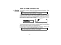
FIRE ALARM PROTECTION
General
Your system may have sensors which detect fire alarm conditions such as smoke
detectors, heat detectors, sprinkler waterflow sensors, etc. You system monitors these
sensors 24 hours a day for continuous protection and provides a number of indications
when a fire alarm condition is detected.
In Case Of Fire
WHEN A FIRE ALARM CONDITION IS DETECTED, EVACUATE ALL
OCCUPANTS FROM THE PREMISES IMMEDIATELY AND NOTIFY
YOUR LOCAL FIRE DEPARTMENT.
Your system provides the following indications when a fire alarm condition is detected:
• The control's buzzer and keypad buzzer produces a slow on/off pulsing sound.
• The external fire alarm sounders produce either:
a steady sound
or
a pulsing sound,
depending on what your installer selected (check the appropriate box).
• The keypad LCD displays the word "FIRE" (Alpha) or "FIRE ALARM" (Fixed-Word) along
with the number of the zone in alarm.
SUPV NO AC
PHONE TEST
NOT READY
CHIME BAT
INSTANT TAMPER
AWAY
BYPASS
STAY
FIRE 05
FILE ROOM
ALARM
FIRE CHECK
ALPHA
FIXED-WORD
• A fire alarm message is sent to the central station.
If your system has a keypad with a FIRE alarm emergency key, then these indications
may be manually triggered by pressing this key for at least 2 seconds, (or the
corresponding emergency key pair), should you become aware of a fire emergency
before your detectors sense the problem.
–14–
FIRE ALARM PROTECTION
Silencing
and Resetting
a Fire Alarm
To silence the control's buzzer, the keypad buzzer and external alarm
sounders:
Press the control's SILENCE/RESET button or enter your
User Code followed by the OFF key at the keypad.
The control's "SILENCED" LED lights and the keypad's LCD will display "FIRE
ALARM SILENCED" (Alpha) or "SF" (Fixed-Word) to indicate that a fire alarm
condition may still be present. The Alpha keypad will display the number of the
zone in alarm as a Memory of Alarm indication. The fixed-word keypad alternates
the zone number in alarm with the "SF" display.
FIRE O5 FIRE
ALARM SILENCED
ALPHA
AWAY
BYPASS
STAY
ALARM
FIRE CHECK
SUPV NO AC
PHONE TEST
NOT READY
CHIME BAT
INSTANT
TAMPER
FIXED-WORD
To reset your system's smoke detectors and the keypad Memory of Alarm
display (after heat or smoke is no longer present):
First determine and correct the cause of the fire alarm condition (e.g., fan smoke from
the smoke detector chamber, reset the pull station, etc.) and then:
Press the control's SILENCE/RESET button again or re-enter
your User Code plus the OFF key at the keypad.
–15–
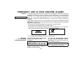
EMERGENCY AND 24 HOUR NON-FIRE ALARMS
General
*Except for silent alarms
Your system may have sensors which detect non-fire related alarm conditions, such as the
unauthorized opening of a stock room door, the triggering of an HVAC (Heating,
Ventilating, or Air Conditioning) temperature sensor, the pressing of a holdup alarm
button, etc. Your system may provide some or all of the indications listed below,
depending on what your installer selected to occur when one of those conditions is
detected.
If your system's keypad has any active emergency alarm key(s) (see REMOTE KEYPAD
EMERGENCY KEYS section) these indications may be manually triggered by pressing the
appropriate emergency key.
• The control's buzzer and keypad buzzer both produce a steady sound*.
• The external alarm sounders produce a steady sound*.
• The keypad LCD (Fixed-Word) displays the word "ALARM" and the zone number in
alarm. Alpha keypads also display a description of the zone in alarm*.
ALARM 02
TEMPERATURE
Silencing
and Resetting
an Emergency Alarm
AWAY
BYPASS
STAY
ALARM
FIRE CHECK
INSTANT
SUPV NO AC
PHONE TEST
NOT READY
CHIME BAT
TAMPER
ALPHA
FIXED-WORD
• An emergency alarm message is sent to the central station.
To silence the control and keypad
To reset the keypad alarm display
buzzers and external alarm
and turn off the SILENCED LED at
sounders:
the control: First correct the cause of the
alarm condition, and then:
Press the control's
SILENCE/RESET button or enter
Press the SILENCE/RESET button
your User Code + the OFF key.
again or re-enter your User Code,
The keypad's LCD will display the
followed by the OFF key.
number of the zone in alarm as
a Memory of Alarm indication.
–16–
BYPASSING PROTECTION ZONES
Using the
6 BYPASS Key
This feature can only be used if a remote keypad has been
installed with the system. User code numbers 2-6 can only be
used to bypass emergency and 24 hour non-fire protected
zones.
This key is used when you want to bypass one or more zones, thus leaving them
intentionally unprotected. For example, a protected stock room door can be
bypassed when it is necessary to open the door without causing an alarm. To
bypass an emergency zone, do the following.
1. Enter your user code and press the BYPASS key.
2. Enter zone number(s) for the zone(s) to be bypassed (e.g., 02, 03, etc.).
Single digit zone numbers must be preceded by a zero.
3. When finished, the keypad will momentarily display a "Bypass" message for
each bypassed zone number. Wait for these zones to be displayed, to confirm
their bypass.
4. A bypass message is sent to the central station.
All emergency zone bypasses are removed when an OFF
sequence (user code plus OFF) is performed.
TYPICAL MOMENTARY DISPLAYS OF BYPASSED ZONE
BYPASS 03 FRONT
UPSTAIRS STORAGE
ALPHA
AWAY
BYPASS
STAY
ALARM
FIRE CHECK
SUPV NO AC
PHONE TEST
NOT READY
CHIME BAT
INSTANT
FIXED-WORD
–17–
TAMPER
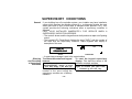
SUPERVISORY CONDITIONS
General
If your building has a fire sprinkler system, your installer may have installed a
sensor which monitors the sprinkler system (e.g., to determine whether the main
water gate valve is open or that there is adequate water pressure, etc.). Your
system provides the following indications when a supervisory condition is
detected.
CALL YOUR INSTALLER IMMEDIATELY FOR SERVICE WHEN A
SUPERVISORY INDICATION APPEARS!
• The control's buzzer and the keypad buzzer both produce a rapid on/off pulsing
sound.
• The keypad LCD (Fixed-Word) displays the word "SUPV" and the number of
the zone with the supervisory condition. Alpha keypads also display a
description of the zone.
SUPV 04
SPRINKLER VALVE
ALPHA
Silencing
and Resetting
a Supervisory
Indication
AWAY
BYPASS
STAY
ALARM
FIRE CHECK
SUPV NO AC
PHONE TEST
NOT READY
CHIME BAT
INSTANT
TAMPER
FIXED-WORD
• A supervisory message is sent to the central station.
To reset the keypad supervisory
To silence the control and keypad
display: First have the cause of the
buzzers:
indication corrected, and then:
Press the control's
SILENCE/RESET button or enter
your User Code, + the OFF key
The keypad's LCD will display the
number of the zone having the
supervisory condition as a Memory
indication.
–18–
Press the SILENCE/RESET button
again or re-enter your User Code,
followed by the OFF key.
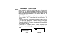
TROUBLE CONDITIONS
General
Your system monitors each of your protection zones and various aspects of
system operation for problems such as wire breaks, loss of AC power, faulted
telephone lines, etc., which compromise proper alarm signaling operation. Your
system provides the following indications when one of these problems is detected.
CALL YOUR INSTALLER IMMEDIATELY FOR SERVICE, WHEN ANY OF
THESE INDICATIONS APPEAR FOR A CONDITION THAT CANNOT BE
CORRECTED BY YOU!
• The control's buzzer and keypad buzzer both produce a rapid pulsing sound.
• The controls AC POWER LED turns off and the keypad LCD displays "AC
LOSS" (Alpha) or "NO AC" (Fixed-Word) when AC power is low or not
present.
• The control's BATTERY TROUBLE LED lights and the keypad LCD displays
"SYSTEM LO BAT" (Alpha) or "BAT" (Fixed-Word) when your system's backup battery is low or disconnected.
• The controls COMM FAIL LED lights and the keypad LCD displays "COMM
FAILURE" (Alpha) or "FC" (Fixed-Word) when attempts to send a message to
the central station have failed.
• The keypad LCD (Fixed-Word) displays "CHECK" accompanied by a
protection zone number (1–5) or system zone number (6–12) when there is a
zone or system related problem. Alpha keypads also display a description of the
zone. The control's LINE FAULT LED lights if the problem is with the telephone
lines.
CHECK 01
WAREHOUSE SMOKE
ALPHA
–19–
AWAY
BYPASS
STAY
ALARM
FIRE CHECK
SUPV NO AC
PHONE TEST
NOT READY
CHIME BAT
INSTANT
FIXED-WORD
TAMPER
TROUBLE CONDITIONS
• A trouble message is sent to the central station.
Note: If your keypad LCD displays "0C" for more than 5 minutes, then it is not
receiving signals from the control. CALL YOUR INSTALLER IMMEDIATELY FOR
SERVICE.
Silencing
and Resetting
a Trouble Indication
To silence the control and keypad
buzzers:
Press the control's
SILENCE/RESET button or enter
your User Code, + the OFF key.
The keypad's LCD will display the
number of the zone in trouble as
a Memory indication.
–20–
To reset the keypad trouble
display: First have the cause of the
trouble condition corrected, and then:
Press the SILENCE/RESET button
again or re-enter your User Code,
followed by the OFF key.
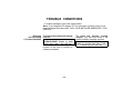
ACTIVATING A FIRE DRILL TEST
Using the
# + 6 + 9 Keys
This feature can be
activated only while no
alarm, supervisory, or
trouble condition is
present.
This test requires that a keypad and external fire alarm sounder be
installed with the system.
Note: Only User Number 2's code can activate this test.
This test activates the external fire alarm sounders for the purpose of conducting a
fire alarm drill. Your system will remain operational for fire alarm signaling while this
test is active (although no message will be sent to the central station unless an
actual alarm occurs).
• To activate the Fire Drill Test:
Enter User Number 2's code, then press the # + 6 + 9 keys.
The keypad LCD will display "FIRE DRILL ACTIVE (Alpha) or "TEST dF"
(Fixed-Word) and the external fire alarm sounders will produce either a steady or
a pulsing sound while this test is active, depending on what your installer
selected.
FIRE DRILL
ACTIVE
ALPHA
AWAY
BYPASS
STAY
ALARM
FIRE CHECK
SUPV NO AC
PHONE TEST
NOT READY
CHIME BAT
INSTANT
TAMPER
FIXED-WORD
• To terminate the Fire Drill Test:
Enter any User Code, followed by the OFF key.
Your system will also automatically terminate this test if an alarm, supervisory or
trouble condition is detected while it is activated.
–21–
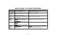
QUICK GUIDE TO SYSTEM FUNCTIONS
FUNCTION
PROCEDURE
COMMENTS
Silence Alarm, Press the SILENCE/RESET button or
Supervisory or Enter user Code + OFF key.
Trouble sounds
SILENCED LED lights. Memory of fault remains until cleared.
Keypad displays # of faulted zone.
Reset Smoke
Detectors &
Displays
Press the SILENCE/RESET button a second
time or
Will reset only if fault corrected.
Manually Trip
Emergency
Alarms
Press key [A], [B], or [C] for at least 2 sec., or
press keys [1]&[Q], or [Q]&[#], or [3]&[#],
both at same time.
Key(s) must be enabled by installer.
Bypass
Emergency
Zone(s)
To bypass, enter user code + BYPASS key +
zone number(s) (use 2-digit entries).
Bypassed zones will not cause an alarm if violated.
Fire Drill Test
To activate: Enter User Number 2's code + # + 6 Activates external fire alarm sounders.
+ 9.
Re-enter user Code + OFF key.
To remove bypass, enter user code + OFF key.
To turn off: Enter any user code + OFF key.
Assign,
change, or
delete user
code.
To assign or change: Enter User Number
To delete: Enter User Number 2's code + CODE key +
2's code + CODE key + user number (2–6) user number (3–6) and stop. Note: User Number 2 can
+ new code.
change but not delete his/her own code.
–22–
SUMMARY OF AUDIBLE/VISUAL NOTIFICATION
ALPHA & FIXED-WORD DISPLAY KEYPADS
SOUND
CAUSE
DISPLAY (Fixed-Word displays are shown in parentheses)
SLOW PULSING Keypad
and, as selected by
installer:
SLOW PULSING or
a. FIRE ALARM
b. FIRE DRILL
a. FIRE plus number and descriptor of zone in alarm (FIRE ALARM plus zone
#).
b. FIRE DRILL ACTIVE (TEST dF)
STEADY
Keypad & External
a. AUDIBLE
EMERGENCY ALARM
a. ALARM plus number and descriptor of zone in alarm (ALARM plus zone #).
RAPID PULSING Keypad
a. SUPERVISORY
a. SUPV plus number and descriptor of zone with SUPV condition (SUPV plus
zone #).
STEADY External,
b. TROUBLE, Fire zone
problem
c. TROUBLE, System
problem
b. CHECK plus number and descriptor of zone (CHECK plus zone #).
c, AC LOSS (NO AC), or SYSTEM LOW BAT (BAT), or COMM FAILURE (FC)
when associated condition detected.
–23–
PROTECTION ZONES LIST
One or more sensing devices will have been assigned by the installer of your alarm system to protection zones 01–05 in
your system. For example, fire sensing devices may have been assigned to zone 05, air conditioning temperature sensors
to zone 02, and so on.
Zone numbers 07, 95 and 96 represent Keypad "emergency" alarm functions assigned by the installer. Zone numbers 06
and 10–13 report system conditions.
This chart may be used to record the specific assignments for your system's zones 01–05, 07, 95 and 96. Your installer will
assist you in recording this information.
Zone
01*
02*
03*
04*
05*
06
07*
PROTECTION ZONE DESCRIPTIONS
Description
– Bell Supervision –
Keypad Emergency Key B (or: ∗ & #)
10
11
12
13
95*
– Earth Ground Supervision –
– Main Dialer Supervision –
– Back-up Dialer Supervision –
– Auxiliary Relay Disable –
Keypad Emergency Key A (or: 1 & ∗)
96*
Keypad Emergency Key C (or: 3 & #)
* To be filled in
–24–
FEDERAL COMMUNICATIONS COMMISSION (FCC) Part 15 STATEMENT
This equipment has been tested to FCC requirements and has been found acceptable for use. The FCC requires the following statement
for your information:
This equipment generates and uses radio frequency energy and if not installed and used properly, that is, in strict accordance with the
manufacturer's instructions, may cause interference to radio and television reception. It has been type tested and found to comply with
the limits for a Class B computing device in accordance with the specifications in Part 15 of FCC Rules, which are designed to provide
reasonable protection against such interference in a residential installation. However, there is no guarantee that interference will not
occur in a particular installation. If this equipment does cause interference to radio or television reception, which can be determined by
turning the equipment off and on, the user is encouraged to try to correct the interference by one or more of the following measures:
• If using an indoor antenna, have a quality outdoor antenna installed.
• Reorient the receiving antenna until interference is reduced or eliminated.
• Move the radio or television receiver away from the receiver/control.
• Move the antenna leads away from any wire runs to the receiver/control.
• Plug the receiver/control into a different outlet so that it and the radio or television receiver are on different branch circuits.
If necessary, the user should consult the dealer or an experienced radio/television technician for additional suggestions. The user or
installer may find the following booklet prepared by the Federal Communications Commission helpful:
"Interference Handbook"
This booklet is available from the U.S. Government Printing Office, Washington, DC 20402.
The user shall not make any changes or modifications to the equipment unless authorized by the Installation Instructions or User's
Manual. Unauthorized changes or modifications could void the user's authority to operate the equipment.
IN THE EVENT OF TELEPHONE OPERATIONAL PROBLEMS
In the event of telephone operational problems, disconnect the control by removing the plug from the RJ31X wall jack. We recommend
that your certified installer demonstrate disconnecting the phones on installation of the system. Do not disconnect the phone
connection inside the control/communicator. Doing so will result in the loss of your phone lines. If the regular phone works correctly
after the control/communicator has been disconnected from the phone lines, the control/communicator has a problem and should be
returned for repair. If upon disconnection of the control/communicator, there is still a problem on the line, notify the telephone company
that they have a problem and request prompt repair service. The user may not under any circumstances (in or out of warranty) attempt
any service or repairs to the system. It must be returned to the factory or an authorized service agency for all repairs.
–25–
FEDERAL COMMUNICATIONS COMMISSION (FCC) Part 68 STATEMENT
This equipment complies with Part 68 of the FCC rules. On the front cover of this equipment is a label that contains, among other
information, the FCC registration number and ringer equivalence number (REN) for this equipment. If requested, this information must
be provided to the telephone company.
This equipment uses the following jacks:
An RJ31X is used to connect this equipment to the telephone network.
The REN is used to determine the quantity of devices which may be connected to the telephone line. Excessive RENs on the telephone
line may result in the devices not ringing in response to an incoming call. In most, but not all areas, the sum of the RENs should not
exceed five (5.0). To be certain of the number of devices that may be connected to the line, as determined by the total RENs, contact
the telephone company to determine the maximum REN for the calling area.
If this equipment causes harm to the telephone network, the telephone company will notify you in advance that temporary discontinuance of service may be required. If advance notice is not practical, the telephone company will notify the customer as soon as
possible. Also, you will be advised of your right to file a complaint with the FCC if you believe necessary.
The telephone company may make changes in its facilities, equipment, operations, or procedures that could affect the operation of the
equipment. If this happens, the telephone company will provide advance notice in order for you to make the necessary modifications in
order to maintain uninterrupted service.
If trouble is experienced with this equipment, please contact the manufacturer for repair and warranty information. If the trouble is
causing harm to the telephone network, the telephone company may request you remove the equipment from the network until the
problem is resolved.
There are no user serviceable components in this product, and all necessary repairs must be made by the manufacturer. Other repair
methods may invalidate the FCC registration on this product.
This equipment cannot be used on telephone company-provided coin service. Connection to Party Line Service is subject to state
tariffs.
This equipment is hearing-aid compatible.
When programming or making test calls to an emergency number, briefly explain to the dispatcher the reason for the call. Perform such
activities in the off-peak hours; such as early morning or late evening.
–26–
WARNING!
THE LIMITATIONS OF THIS ALARM SYSTEM
While this system is an advanced design security system, it does not offer guaranteed protection against burglary or fire or other
emergency. Any alarm system, whether commercial or residential, is subject to compromise or failure to warn for a variety of reasons.
For example:
• Intruders may gain access through unprotected openings or have the technical sophistication to bypass an alarm sensor or
disconnect an alarm warning device.
• Intrusion detectors (e.g. passive infrared detectors), smoke detectors, and many other sensing devices will not work without power.
Battery operated devices will not work without batteries, with dead batteries, or if the batteries are not put in properly. Devices
powered solely by AC will not work if their AC power supply is cut off for any reason, however briefly.
• Signals sent by wireless transmitters may be blocked or reflected by metal before they reach the alarm receiver. Even if the signal
path has been recently checked during a weekly test, blockage can occur if a metal object is moved into the path.
• A user may not be able to reach a panic or emergency button quickly enough.
• While smoke detectors have played a key role in reducing residential fire deaths in the United States, they may not activate or
provide early warning for a variety of reasons in as many as 35% of all fires, according to data published by the Federal Emergency
Management Agency. Some of the reasons smoke detectors used in conjunction with this System may not work are as follows.
Smoke detectors may have been improperly installed and positioned. Smoke detectors may not sense fires that start where smoke
cannot reach the detectors, such as in chimneys, in walls, or roofs, or on the other side of closed doors. Smoke detectors also may
not sense a fire on another level of a residence or building. A second floor detector, for example, may not sense a first floor or
basement fire. Moreover, smoke detectors have sensing limitations. No smoke detector can sense every kind of fire every time. In
general, detectors may not always warn about fires caused by carelessness and safety hazards like smoking in bed, violent
explosions, escaping gas, improper storage of flammable materials, overloaded electrical circuits, children playing with matches, or
arson. Depending upon the nature of the fire and/or the locations of the smoke detectors, the detector, even if it operates as
anticipated, may not provide sufficient warning to allow all occupants to escape in time to prevent injury or death.
• Passive Infrared Motion Detectors can only detect intrusion within the designed ranges as diagrammed in their installation manual.
Passive Infrared Detectors do not provide volumetric area protection. They do create multiple beams of protection, and intrusion can
only be detected in unobstructed areas covered by those beams. They cannot detect motion or intrusion that takes place behind
walls, ceilings, floors, closed doors, glass partitions, glass doors, or windows. Mechanical tampering, masking, painting or spraying
of any material on the mirrors, windows or any part of the optical system can reduce their detection ability. Passive Infrared
Detectors sense changes in temperature; however, as the ambient temperature of protected area approaches the temperature range
of 90° to 105°F (32° to 40°C), the detection performance can decrease.
(continued)
–27–
(continued) WARNING! THE LIMITATIONS OF THIS ALARM SYSTEM
• Alarm warning devices such as sirens, bells or horns may not alert people or wake up sleepers if they are located on the other side of
closed or partly open doors. If warning devices sound on a different level of the residence from the bedrooms, then they are less
likely to waken or alert people inside the bedrooms. Even persons who are awake may not hear the warning if the alarm is muffled
from a stereo, radio, air conditioner or other appliance, or by passing traffic. Finally, alarm warning devices, however loud, may not
warn hearing-impaired people or waken deep sleepers.
• Telephone lines needed to transmit alarm signals from a premises to a central monitoring station may be out of service or temporarily
out of service. Telephone lines are also subject to compromise by sophisticated intruders.
• Even if the system responds to the emergency as intended, however, occupants may have insufficient time to protect themselves
from the situation. In the case of a monitored alarm system, authorities may not respond appropriately.
• This equipment, like other electrical devices, is subject to component failure. Even though this equipment is designed to last as long
as 10 years, the electronic components could fail at any time.
The most common cause of an alarm system not functioning when an intrusion or fire occurs is inadequate maintenance. This alarm
system should be tested weekly to make sure all sensors and transmitters are working properly.
Wireless transmitters (used with some systems) are designed to provide long battery life under normal operating conditions. Longevity
of batteries may be as much as 4 to 7 years, depending on the environment, usage, and the specific wireless device being used.
External factors such as humidity, high or low temperatures, as well as large swings in temperature, may all reduce the actual battery
life in a given installation. This wireless system, however, can identify a true low battery situation, thus allowing time to arrange a
change of battery to maintain protection for that given point within the system.
Installing an alarm system may make one eligible for lower insurance rates, but an alarm system is not a substitute for insurance.
Homeowners, property owners and renters should continue to act prudently in protecting themselves and continue to insure their lives
and property.
We continue to develop new and improved protection devices. Users of alarm systems owe it to themselves and their loved ones to
learn about these developments.
SERVICING INFORMATION
Your local authorized service representative is the person best qualified to service your alarm system. Arranging a
regular program with that person is advisable. Your local service representative is:
NAME: _____________________________________________PHONE: __________________________
ADDRESS: ______________________________________________________________________________
______________________________________________________________________________
–28–
ADEMCO ONE YEAR LIMITED WARRANTY
Alarm Device Manufacturing Company, a Division of Pittway Corporation, and its divisions, subsidiaries and affiliates ("Seller"), 165
Eileen Way, Syosset, New York 11791, warrants its security equipment (the "product") to be free from defects in materials and
workmanship for one year from date of original purchase, under normal use and service. Seller's obligation is limited to repairing or
replacing, at its option, free of charge for parts, labor, or transportation, any product proven to be defective in materials or
workmanship under normal use and service. Seller shall have no obligation under this warranty or otherwise if the product is altered or
improperly repaired or serviced by anyone other than the Seller. In case of defect, contact the security professional who installed and
maintains your security equipment or the Seller for product repair.
This one year Limited Warranty is in lieu of all other express warranties, obligations or liabilities. THERE ARE NO EXPRESS
WARRANTIES, WHICH EXTEND BEYOND THE FACE HEREOF. ANY IMPLIED WARRANTIES, OBLIGATIONS OR LIABILITIES MADE
BY SELLER IN CONNECTION WITH THIS PRODUCT, INCLUDING ANY IMPLIED WARRANTY OF MERCHANTABILITY, OR FITNESS
FOR A PARTICULAR PURPOSE OR OTHERWISE, ARE LIMITED IN DURATION TO A PERIOD OF ONE YEAR FROM THE DATE OF
ORIGINAL PURCHASE. ANY ACTION FOR BREACH OF ANY WARRANTY, INCLUDING BUT NOT LIMITED TO ANY IMPLIED
WARRANTY OF MERCHANTABILITY, MUST BE BROUGHT WITHIN 12 MONTHS FROM DATE OF ORIGINAL PURCHASE. IN NO CASE
SHALL SELLER BE LIABLE TO ANYONE FOR ANY CONSEQUENTIAL OR INCIDENTAL DAMAGES FOR BREACH OF THIS OR ANY
OTHER WARRANTY, EXPRESS OR IMPLIED, OR UPON ANY OTHER BASIS OF LIABILITY WHATSOEVER, EVEN IF THE LOSS OR
DAMAGE IS CAUSED BY THE SELLER'S OWN NEGLIGENCE OR FAULT. Some states do not allow limitation on how long an implied
warranty lasts or the exclusion or limitation of incidental or consequential damages, so the above limitation or exclusion may not apply
to you.
Seller does not represent that the product may not be compromised or circumvented; that the product will prevent any personal injury or
property loss by burglary, robbery, fire or otherwise; or that the product will in all cases provide adequate warning or protection. Buyer
understands that a properly installed and maintained alarm may only reduce the risk of a burglary, robbery, fire or other events
occurring without providing an alarm, but it is not insurance or a guarantee that such will not occur or that there will be no personal injury
or property loss as a result. CONSEQUENTLY, SELLER SHALL HAVE NO LIABILITY FOR ANY PERSONAL INJURY, PROPERTY
DAMAGE OR OTHER LOSS BASED ON A CLAIM THE PRODUCT FAILED TO GIVE WARNING. HOWEVER, IF SELLER IS HELD LIABLE, WHETHER DIRECTLY OR INDIRECTLY, FOR ANY LOSS OR DAMAGE ARISING UNDER THIS LIMITED WARRANTY OR
OTHERWISE, REGARDLESS OF CAUSE OR ORIGIN, SELLER'S MAXIMUM LIABILITY SHALL NOT IN ANY CASE EXCEED THE
PURCHASE PRICE OF THE PRODUCT, WHICH SHALL BE THE COMPLETE AND EXCLUSIVE REMEDY AGAINST SELLER. This
warranty gives you specific legal rights, and you may also have other rights which vary from state to state. No increase or alteration,
written or verbal, to this warranty is authorized.
–29–
A Division of Pittway Corporation
165 Eileen Way, Syosset, New York 11791
N8028 4/96
Copyright © 1995 PITTWAY CORPORATION
–30–