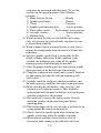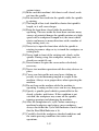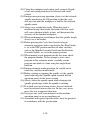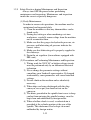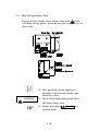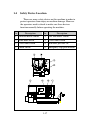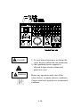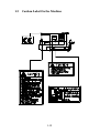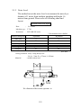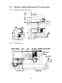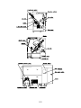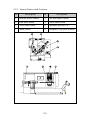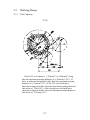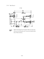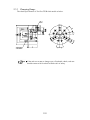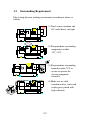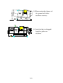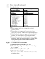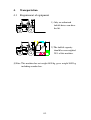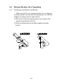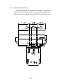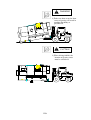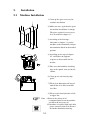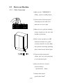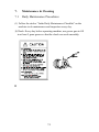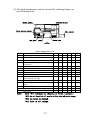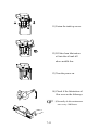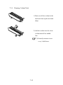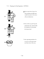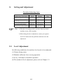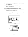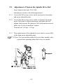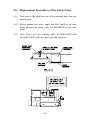
1
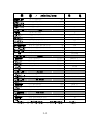
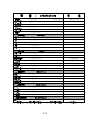
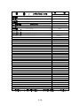
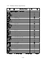
T-7M
SIEMENS 802D-SL
VER:IM-T074300
NO:P20ABET7MS
LEADWELL
T-7M(802D-SL)
INSTRUCTION
MANUAL
P20ABET7MS
PREFACE
Thank you for purchasing the CNC MACHINE TURNING CENTER. We at
Leadwell are confident your purchase will greatly expand your work capacity and
efficiency. This instruction manual has been prepared to assist you on ordering
replacement, servicing parts, technical problem and maintenance. If you have any question
on your machine or this publication, please contact your Leadwell dealer or local agent.
I
BRIEF INTRODUCTION OF LEADWELL
Founded in 1980, Leadwell CNC Machines Mfg., Corp., is now the most professional
CNC machine tool maker in Taiwan. Leadwell is constantly searching for perfection by
upgrading the performance, product quality and reliability of its products which range
from CNC Vertical /Horizontal Machining Centers, Turning Centers, Plastic Injection
Molding Machines, Grinders, Tapping/Drilling Machines to Laser Cutting Machines,
5-face Machining Centers, Double Housing Planking Machine, Flexible Manufacturing
Systems(FMS) .
In 1993 Leadwell received the Outstanding Product Award --SYMBOL OF
EXCELLENCE and its quality passed ISO 9002 recognition.
Hence, Leadwell products
are recognized as highly reliable. In October, 1997 Leadwell has received the National
Quality Award by the Executive Yuan, R.O.C.
quality management with outstanding result.
We have developed our products total
January of 1999, the grate month, Leadwell
passed a certification of CNS 14001 from the Bureau of Commodity Inspection And
Quarantine(BCIQ) Ministry of Economic Affairs Taiwan.
The highest guiding principle for quality management in Leadwell is 『Quality is our
life and dignity』, we constantly work for developing more high quality, more high
technical and offer faster service. We also go after excellent quality and management to
win the custmors’ respect to be No.1 all over the world.
II
CHANGES AND COPYING
Leadwell reserves the right to make any change or modification to this manual
without giving previous notice and without incurring any obligation. If you reproduce or
transmit in any form or by any means without the written permission of Leadwell to
destroy reputation of Leadwell, we will reserve the power of prosecution.
◎Copyright 2002 Leadwell CNC Machines Mfg., Corp. All rights reserved.
III
Table of Contents
1. Safety Regulation
1.1 Check Points for Safe Operation………………………………………….. 1-1
1.2 Safety Rules for this machine.
1-2
1.2.1 Safety Practice………………………………………………………… 1-2
1.2.2 Machine Installation Precautions……………………………………... 1-3
1.2.3 Turning The Power On and Off………………………………………. 1-7
1.2.4 Safety Practice During Machine Operation…………………………… 1-7
1.2.5 Safety Practices during Maintenance & Inspection…………………...
1.2.6 To Ensure High Accuracy……………………………………………..
1.2.7 Precautions when selecting Coolant…………………………………...
1.2.8 Precautions When Operating Special Specification…………………...
1.2.9 Front Cover Window Glass……………………………………………
1-11
1-12
1-13
1-14
1-14
1.3 Machine Potential Danger Explanation…………………………………… 1-15
1.3.1 Machine Potential Danger Zone………………………………………. 1-15
1.3.2 High-Voltage Danger Zone…………………………………………… 1-16
1.4 Safety Device Location………………………………………………….… 1-17
1.5 Caution Label On the Machine………………………………………….… 1-19
2. Machine Brief Introduction
2.1 Machine Introduction & Noise Level……………………………………... 2-1
2.1.1 Machine Introduction…………………………………………………. 2-1
2.1.2 Noise Level…………………………………………………………… 2-3
2.2 Machine Outline Dimension & Nomenclature……………………………. 2-4
2.2.1 Machine Outline Dimension………………………………………….. 2-4
2.2.2 Nomenclature…………………………………………………………. 2-4
2.2.3 Sensor/Limit switch Location………………………………………… 2-6
2.3 Working Range……………………………………………………………. 2-7
2.3.1 Tool Capacity…………………………………………………………. 2-7
2.3.2 Tool Travel……………………………………………………………. 2-9
2.3.3 Clamping Range………………………………………………………. 2-10
2.3.4 Spindle Nose End & Tailstock Taper Dimension…………………….. 2-11
2.4 Machine Specification…………………………………………………….. 2-12
2.4.1 Machine Hardware Specification……………………………………... 2-12
2.4.2 Machine Software Specification……………………………………… 2-16
2.4.3 Spindle Motor Torque Curve…………………………………………. 2-20
2.4.4 Turret Motor Torque Curve…………………………………………… 2-21
2.5 Tooling Diagram………………………………………………………….. 2-22
3. Preparation before Machine setup
3.1 Foundation Requirement…………………………………………………... 3-1
3.2 Surrounding Requirement…………………………………………………. 3-2
3.3 Power Source Requirement…...…………………………………………… 3-4
3.3.1 Power Specification…………………………………………………… 3-4
3.3.2 Oil Specification………………………………………………………. 3-5
3.3.3 Air Specification……………………………………………………… 3-6
4. Transportation
4.1
4.2
4.3
4.4
Requirement of equipment….……………………………………………... 4-1
Marking on Wooden Case………………………………………………… 4-2
Unpacking Machine……………………………………………………….. 4-3
Moving Machine after Unpacking………………………………………… 4-4
4.4.1 Confirming Fixed Bracket on Machine…………….…………………. 4-4
4.4.2 Fork Lifting Machine…………………………………………………. 4-5
4.5 Relocating of Machine…………………………………………………….. 4-7
5. Installation
5.1 Machine Installation….……………………..……………………………... 5-1
5.2 Power On Machine…………………………...…………………………… 5-2
5.2.1 Cable Connection……………………………………………………... 5-2
5.2.2 Inspection before Power On…………………………………………... 5-3
5.2.3 Inspection after Power On…………………………………………….. 5-4
5.3 Level Adjustment………………………………………………………….. 5-6
5.4 Test-cutting……………………………………………………………...… 5-7
5.4.1 Checklist before Test-cutting…………….…………………...………. 5-7
5.4.2 Warming up machine…………………………………………………. 5-8
5.4.3 Testing-Cutting………………………………………………………... 5-9
6. Operation Instruction (please refer to operation manual)
7. Maintenance & Cleaning
7.1 Daily Maintenance Procedures.………….....……………………………... 7-1
7.1.1 Daily Inspection after Operation…………………………………….... 7-4
7.2 Monthly Maintenance Procedures………………..……………………….. 7-6
7.3 Periodic Maintenance Procedures…………………..…………………...… 7-7
7.3.1 Check List…………….…………………………..…………...………. 7-7
7.3.2 Cleaning Lubricator Tank……………………………….……………. 7-8
7.3.3 Cleaning Hydraulic Tank……………………………………………... 7-12
7.3.4 Cleaning Coolant Tank………………………………………………... 7-13
7.3.5 Cleaning Air Filter Regulator…………………………………………. 7-14
8. Setting & Adjustment
8.1
8.2
8.3
8.4
Level Adjustment….……………………..………………………………... 8-1
Hydraulic Pressure setting & Adjustment…………………….…………… 8-2
Lubricator setting & Adjustment………………………………………….. 8-3
Tailstock Sensor Adjustment……………………………………………… 8-4
9. Maintenance
9.1
9.2
9.3
9.4
9.5
9.6
Maintenance of the Limit Switch on X Axis………………….………...… 9-1
Maintenance of the Limit Switch on Z Axis…………………………..….. 9-2
Maintenance of the Tool Setter Arm Sensor………………………….…… 9-3
Maintenance of the Limit Switch on the Splash Guard…………………… 9-4
Tension Adjustment of the Spindle Drive Belt……………………………. 9-5
Replacement Procedures of the Safety Glass……………………………… 9-6
Safety Regulation
Contents
1. Safety Regulation
1.1 Check Points for Safe Operation………………………………………….. 1-1
1.2 Safety Rules for this machine.
1-2
1.2.1 Safety Practice………………………………………………………… 1-2
1.2.2 Machine Installation Precautions……………………………………... 1-3
1.2.3 Turning The Power On and Off………………………………………. 1-7
1.2.4 Safety Practice During Machine Operation…………………………… 1-7
1.2.5 Safety Practices during Maintenance & Inspection…………………... 1-11
1.2.6 To Ensure High Accuracy…………………………………………….. 1-12
1.2.7 Precautions when selecting Coolant…………………………………... 1-13
1.2.8 Precautions When Operating Special Specification…………………... 1-14
1.2.9 Front Cover Window Glass…………………………………………… 1-14
1.3 Machine Potential Danger Explanation…………………………………… 1-15
1.3.1 Machine Potential Danger Zone………………………………………. 1-15
1.3.2 High-Voltage Danger Zone…………………………………………… 1-16
1.4 Safety Device Location………………………………………………….… 1-17
1.5 Caution Label On the Machine………………………………………….… 1-19
1.
Safety Regulation.
1.1
Check Points for Safe Operation
When using your CNC lathe, always make sure the following
conditions or operations are in effect. Failure to this will reduce
cutting accuracy and may be the cause of accidents.
(1).When chucking a workpiece, check both the chucking method
and the pressure while considering the rigidity of the workpiece
so as not to cause chucking distortion.
(2).Make sufficient chucking allowance so that the workpiece cannot
jump out from the chuck, either by cutting force or centrifugal
force of the spindle. The workpiece may be supported by the
tailstock, if necessary.
(3).If the workpiece is an eccentric or irregular shape, so that the
center of gravity or the workpiece is outside the center of rotation,
this eccentricity will cause the spindle vibrate during rotation,
adversely affecting overall cutting accuracy. To counteract this,
attach a balance for the workpiece.
(4).If chips are stuck to the workpiece or to the tool, the desired
accuracy of cutting face may not be obtained, Select appropriate
tools to prevent chips from sticking to the tool and workpiece
(5).Before selecting tools, check the tools thoroughly so as to
prevent any interference between the tool and workpiece, chuck,
jaw, tailstock, cover, etc..
(6).A wide variety of materials and shapes are used as workpieces to
be cut. Always set the appropriate cutting conditions for each
material and shape to obtain the desired accuracy of the
particular product.
(7).At actuation of the machine an before cutting, warm up the
spindle and move the turret and slideways for a period of time to
reach proper operating temperature. This is necessary to reduce
the influence on the workpiece by thermal displacement.
(8).When cutting the bar material using a bar feeder and a hole
through spindle, use only absolutely straight bar material since
the accuracy of the workpiece is influenced by curve of the bar
material.
1-1
1.2
Safety Rules for this machine
1.2.1 Safety Practices
Each machine is shipped with a variety of built-in safety devices.
To prevent such a situation from occurring, all operators must
carefully read the manual supplied by NC unit manufacturer and
Leadwell so that they understand the machine before trying to
operate it.
Because there are so many "things which cannot be done" and
"things which must not be done, "all prohibited information cannot
be specified in the instruction manual. Assume that something is
impossible unless the manual specifically states that "it can be
done".
The following pages describe fundamental safety information.
All the items described must be carefully observed when operating
the machine or performing maintenance work. Failure to observe
fundamental safety information can lead to serious operator injury
and machine damage. All operators must strictly follow the
information.
[Signal Word Definition]
DANGER
Indicates an imminently hazardous situation which, if not
avoided, will result in death or serious injury.
WARNING
Indicates a potentially hazardous situation which, if not
avoided, could result in death or serious injury.
CAUTION
Indicates a potentially hazardous situation which, if not
avoided, may result in minor or moderate injury or damages
to the machine.
NOTE
Indicates comments and items for which car should be
exercised.
CONTACT
Indicates should contact with service department .
1-2
1.2.2 Machine Installation Precautions
Installation Site:
(1) Allow space for maintenance.
Install the machine so that the doors of the machine and
the NC unit can be opened without interference.
(2) Do not put things on the floor around the machine.
Keep the floor dry. If coolant or lubricating oil is spilled.
Wipe it up immediately.
(3) The machine and the NC unit must not be subject to
direct sunlight. Chips, coolant, and oil must not be
splashed on the machine or the NC unit.
The machine and the NC unit must not subject to any
excessive vibrations.
Ambient temperature: 0 to 40
Humidity: 75%RH or lesswithout condensation
(4) Make sure that the floor is strong enough to support the
machine. The floor must not be sloped or irregular in any
way.
(5) A number of cooling fans are used inside the floor.
Therefore, dust and mist must be kept to a minimum.
(6) Allow space for easy removal of the chip conveyor and
the coolant tank.
Power Supply:
(1) Only an authorized electrical technician should perform
work with the power cable connections.
(2) No electrical noise generating sources, such as electric
welders or electric discharge machines, can be near the
machine. Take care to insulate the machine from any
adverse effects that might be caused by nearby
equipment.
(3) An excessive voltage drop due to an insufficient power
capacity will cause a malfunction of the NC unit. The
power cables must be connected directly and
independently to the plant power distribution panel.
1-3
Allowable values:
*Voltage…………………….…10% of nominal supply
voltage.
*Frequency……………………50/60 Hz 1 Hz.
*Momentary power failure…....Less than 10 msec.
*Voltage impulse……………...Leak value is 200% or less of
the effective value (rms value)
of the line voltage with pulse
duration of 1.5 msec.
*Waveform distortion…………7% or less
*Imbalance in line voltages……5% or less
Grounding:
(1) The machine must be grounded independently of other
machines.
(2) If electric welders or electric discharge machines are
grounded to the frame of the plant building, do not
connect the ground wire of the machine to the plant
frame.
(3) The ground wire must be as short as possible and have the
same diameter as the input power cable.
Class 3 ground
Grounding resistance: 100 or less
(4) Please measures the ground wire to earth, exactly.
The grounding resistance must be less than 100 with the
single device.
1-4
Air Supply:
(1) Use only clean and dry air.
(2) Make sure that the air source can supply the specified
volume of air.
Installation:
(1) To hoist the machine, be sure to follow the precautions
bellow.
1) Only an authorized technician should perform work
with the machine hoistion.
2) Use only wires, shackles, and jigs of the dimensions
specified in the manual. They must be strong enough
to support the weight of the machine.
3) Before hoisting the machine, make sure that each of
the units is fixed securely.
4) Before hoisting the machine, make sure that each of
the units is fixed securely.
5) Be sure that the machine is well balanced both
lengthwise and crosswise while hoisting the machine
slightly shove the floor.
6) When a plurality of workers are in operation, be sure
to call attention each other as necessary.
(2) If rust prevention coating is applied to the slideway
surfaces, it must be removed completely. If any rust
prevention coating is left on the slideway when the
machine power is turned ON, a servo alarm will occur.
(3) The carriage and cross slide are fixed in place with transit
clamps when the machine is shipped. Also, eyebolts are
used to hoist the machine. These clamps and eyebolts
must be removed before turning ON the power.
(4) After installing the machine, the machine must be leveled.
The machine's crown and distortion values must be
adjusted according to the Accuracy Test Results Chart
delivered with the machine.
(5) Keep the door interlock switch in the ON position.
Remove the key and store it in a safe place.
1-5
Before turning On The Power After Installation:
After completing machine installation, check the following
points before turning ON the power
(1) Make sure that all bolts are tightened securely
(2) Make sure that all connectors are connected securely
(3) Make sure that all hydraulic hoses and air pipes are
connected securely.
(4) If the machine is equipped with any optional external
equipment (bar feeder, loader, robot), make sure that each
electrical cable and hydraulic/pneumatic pipes are
connected correctly.
(5) Check the input voltage and all the L1/L2/L3 (R/S/T)
phases of input power.
After Turning ON The Power After Installation:
(a) Never feed the axes right away after turning ON the
power; manually operate the cycle pump to supply
lubricating oil to the slideway surfaces first.
(b) Check for oil leaks. Make sure that all of the gauges
indicate the correct values.
(c) Make sure that any transit clamps left in the machine are
removed.
(d) Repeatedly open and close the chuck to break in the
chuck operation cylinder. Then, break in the spindle.
1-6
1.2.3 Turning the Power On and Off
(1) Always check that there are no obstacles or people near
the machine's movable parts before operating the
machine.
(2) If the machine stops due to a power failure, turn the Main
Disconnect Switch OFF immediately.
(3) The machine cannot operate unless the power is supplied
correctly. A momentary power stoppage due to a power
failure or lightning can cause an accident. Therefore, stop
the machine of abnormal fluctuation of power supply due
to lightning, etc. Is anticipated.
(4) Before starting machine operation, make sure that all of
the gauges (hydraulic pressure, lubricating oil pressure,
compressed air pressure, etc.) indicate the correct values.
Air should always be supplied to a machine equipped
with a parts catcher.
(5) After turning the power ON, make sure that the cycle
pump and the fans are operating correctly.
(6) Never feed the axes right after turning the power ON;
manually operate the cycle pump to supply lubricating oil
to the slideway surfaces first. Also, break in the spindle
for at least 15 minutes.
(7) To turn the power OFF, follow the sequence below:
-Press the Emergency Stop Button.
-Press the POWER OFF Switch on the operation panel.
-Turn the Main Disconnect Switch OFF.
1.2.4 Safety Practices during Setup and Operation
(1) Never touch any switch with wet hands.
(2) The machine should be operated by one, well-trained
person only, at any time, injury can occur if more than
one person operates the machine; the machine could be
started by one operator while the other operator is
changing the fixture or chuck jaws. If more than one
operator is absolutely necessary, all involved operators
must cooperate and be able to communicate.
(3) Always turn the power OFF before performing setup. If
1-7
setup must be performed with the power ON, set the
switches on the operation panel to the following
positions:
1) Mode Selector Switch......................Handle
2) Spindle speed range.........................Natural
3) Chuck...............................................Unclamp
4) Spindle speed adjusting dial.............Lowest position
5) Turret index switch.........To the current turret position
6) Override switches.............................Lowest position
7) Machine lock....................................On
(4) When loosening the bolts on tool holders and cutting
tools, or loosening the tailstock body clap bolts, be sure
to loosen them gradually.
(5) When a manual chuck or manual fixture is used, always
remove the clamp handle from the chuck or fixture after
tightening.
(6) Specify a spindle speed which is permissible for the
chuck, cylinder, and fixture. If this condition is not
satisfied, the workpiece may come off the spindle,
injuring operators and damaging the machine.
(7) Select the proper chucking pressure and tailstock spindle
thrust pressure for the desired type of machining.
(8) Clamp the workpiece and cutting tools securely. Depth of
cut and cutting feed must be selected beginning with
small values.
(9) Carefully check the workpiece chucked conditions and
the center pressing conditions for center work operations.
(10) Make sure that the tool holders, tools, soft jaws, and
tailstock are all tightened securely. They should be
mounted and well balanced so that they will not interfere
with the workpiece or the machine.
(11) Be careful not to operate the wrong switch. Visually
check the switches on the operation panel before
operating them.
(12) The halogen lamp will be very hot after it gas been lit for
a long period. Be careful not to touch it.
(13) Always lower the spindle speed when changing the
spindle speed range while the spindle is rotating.
(14) While operate machine, do not touch or close to
movement zone, turning or movable unit will cause
1-8
serious injury.
(15) Make sure that machine's left door is well closed, or do
not turn the spindle.
(16) Do not insert bar stock into the spindle while the spindle
is rotating.
(17) The length of bar stock should be shorter that spindle's
length, or it will cause danger.
(18) Keep the front door closed while the machine is
operating. The area inside the front door contains many
sources of potential danger-the spindle rotation at a high
speed with a workpiece clamped in it, the turret which
rotates and moves in many directions with a number of
sharp cutting tools, etc.
(19) Never try to open the front door while the spindle is
rotating to remove chips or try to touch the workpiece or
cutting tools.
(20) Never stand in front of the rotating unit, chuck, or the
spindle. During setup, the workpiece, cutting tools, or
chuck jaws might fly out.
(21) Never remove or open the covers unless absolutely
necessary.
(22) Never start machine operation with the safety devices in
place.
(23) Cover your hair and do not wear loose clothing or
jewelry to avoid becoming tangled or caught in the
machine. Always wear proper shoes when operating the
machine.
(24) Do not lean on the machine while the machine is
operating. Leaning on the covers can be very dangerous.
(25) Specify a spindle speed which is permissible for the
chuck, cylinder, and fixture. If this condition is not
satisfied, the workpiece may come off the spindle,
injuring operators and damaging the machine.
(26) After the completion of a cycle, before removing a
machined workpiece and setting a new workpiece,
always check that the Cycle Start Indicator is not lit and
that the Feed Hold Indicator is lit.
(27) Carefully check the workpiece chucked conditions and
the center pressing conditions for center work
operations.
1-9
(28) Clamp the workpiece and cutting tools securely. Depth
of cut and cutting feed must be selected with small
valued.
(29) During center pressing operation, always set the tailstock
spindle interlock to the ON position so that the cycle
will not start until the workpiece is held by the tailstock
spindle center.
(30) Always use straight bar stocks. When bar stock is
machined using a bar feeder, the bend of the bar stock
will cause vibration which, in turn, will deteriorate the
accuracy of the finished workpiece.
(31) When machining bar stock longer than the spindle length,
always use a bar feeder.
(32) Before pressing the Cycle Start Switch to begin
automatic operation, make sure that the Dry Run Switch
is set in the OFF position and that all other switches,
such as the Spindle Override Switch and the Feedrate
Override Switch, are set to the proper position.
(33) When running a new program for the first time, check
the program number. Never attempt to start a new
program in the automatic made; carefully run the
program one block at a time using the single block
function.
(34) During automatic mode operation, be careful not to
touch any switches inadvertently.
(35) Before starting or stopping the spindle, set the spindle
speed adjusting dial (spindle speed override dial on
operation panel) to the lowest setting.
(36) Always lower the spindle speed when changing the
spindle speed range while the spindle is rotating.
(37) If an hard over travel alarm occurs, the axis interlock
must be released to move the axis. In this case, never
move the axis in opposite direction.
(38) Never put any tools or instruments on the machine
operation panel or on any machine part.
(39) A machine with special specifications, must be operated
in accordance with the specification.
1-10
1.2.5 Safety Practices during Maintenance and Inspection
Always turn OFF the power before performing
maintenance and inspection. Maintenance and inspection
inside the cover is especially dangerous.
(1) Daily Maintenance:
In order to ensure safe operations, the machine must be
maintained and inspected daily.
1) Clean the machine so that any abnormalities can be
found easily.
2) During dry cutting or when machining cast-iron
workpieces, carefully remove chips from the machine
not to accumulate them.
3) Make sure that the gauges for hydraulic pressure, air
pressure, and lubricating oil pressure indicate the
correct values.
4) Make sure that lubricating oil is properly supplied to
the slideways.
5) Drain the air regulator (for machines equipped with
FRL unit).
(2) Precautions on Performing Maintenance and Inspection:
1) Wiring work for 200V AC or higher voltage circuits
must be performed only by an authorized electrical
technician.
2) Never change the parameter settings without
consulting your Leadwell representative. If changed
inadvertently, some parameters will cancel interlock
settings.
3) Do not climb on the machine unless absolutely
necessary.
4) When chips are being discharged with the chip
conveyor, never put your hand or foot on the
conveyor.
5) The drain, provided in the spindle front cover to keep
coolant from entering the spindle bearings, must be
kept clean and unblocked by foreign matter.
6) When a hollow chuck is used, a coolant drain is
provided at the cylinder portion at the rear of the
spindle. This drain must also be kept clean and
unblocked by foreign matter.
1-11
7) Disassemble and clean the chuck periodically. Apply
grease to the chuck every day.
8) The solenoid valves become very hot when the
machine is operating. Be very carefully not to touch
them after the power in turned OFF.
9) Supply or change hydraulic oil or lubricating oil as
specified in the Instruction Manual.
10) Use only fresh, uncontaminated lubricating oil as
specified in the Instruction manual. Clean the
reservoirs and filers in the lubrication line periodically
and check for damages to the lubrication equipment
and piping.
11) The fan and filers in the electrical cabinet must be
kept clean.
12) Do not open the doors of the electrical cabinet, the
NC unit, or the operation panel unless absolutely
necessary. Opening the doors allows dust, foreign
matter, and moisture to enter the enclosure and can
cause machine malfunctions.
13) Before changing the battery for memory back up,
make sure that the power in turned ON. If the battery
is changed with power OFF, all programs, parameters,
and other data stored in memory will be lost.
14) The halogen lamp will be very for after it has been lit
for a long period. Be careful not to touch it.
15) Carry out daily, monthly, and semi-annual inspection
as specified in the Instruction Manual.
1.2.6 To Ensure High Accuracy
When operating a CNC lathe, the accuracy of the finished
product cannot be maintained unless the following check
points are observed. Failure to observe these check points
can also cause to accidents.
Check Points:
(1) Allow a sufficient clamping area so that the workpiece
will not come out of the chuck due to the cutting fore of
centrifugal force generated by spindle rotation.
Depending on the shape of the workpiece, it may need to
1-12
be supported by the tailstock.
(2) When chucking a workpiece, determine the chucking
method and chuck pressure considering the rigidity of the
workpiece so that the workpiece will not be distorted by
the chuck.
(3) Machine vibration will result when workpiece with its
center of gravity not at the chuck rotating center is rotated
in the chuck. This, in turn, will deteriorate the accuracy of
the machined workpiece.
(4) Careless tooling will cause interference between the tools
and the workpiece being cut or the tailstock. Check the
tooling carefully to avoid interference.
(5) Before starting the day's operation, break in the spindle
and the axes. This will minimize the influence of thermal
distortion on workpiece accuracy.
(6) When bar stock is used, its bend has veridical influence
on the accuracy of the machined workpiece. Use straight
workpieces only.
(7) If any chips are entangled on the wlrkpiece or cutting tool,
surface roughness will be deteriorated. Select a cutting
tool which will not entangle chips.
(8) Workpiece materials and shapes will vary widely. It is
necessary to select the cutting conditions best suited to
each workpiece in order to obtain the required accuracy.
(9) When forged or cast workpiece are used, the cutting
allowance varies greatly from the finished dimensions. To
avoid this variation, either write a program in which takes
the variation into consideration or perform pre-machining
so that a uniform cutting allowance is left on the
workpiece.
1.2.7 Precautions when Selecting coolant
There are a variety of types of coolant available on the
market. We do not specify the type of coolant to be used.
Choose a coolant suitable for the user's applications by
consulting the supplier, taking the following requirements
into consideration.
(1) The coolant must be free of constituents with adverse
1-13
effects (smell, poisoning, etc.) on human beings.
(2) The coolant must not deteriorate during storage.
(3) The coolant must not cause corrosion of the machine.
(4) The coolant must not peel the coating off the machine.
(5) The coolant must not cause swelling of rubber parts.
(6) The coolant must not cause deterioration of accuracy.
Note:Leadwell cannot be held responsible for any trouble
arising from the use of coolant.
1.2.8 Precautions When Operating Special Specification Machines
(1) Industrial robot specification:
Only properly authorized persons trained and approved
in accordance with local regulations may operate the
robots. Unauthorized persons may not operate the robots
for any reason, including teaching and inspection.
Anyone working with the robot operators must also be
properly authorized.
1.2.9 From Cover Window Glass
The front cover window glass will not break when hitting
by chips generated during machining. However, there are
instance (due to improper operation) when this glass has been
broken by a workpiece, soft jaws, or a fixture. In such cases,
the customer will be charged for replacing the broken glass.
1-14
1.3
Machine Potential Danger Explanation
1.3.1 Machine Potential Danger Zone
During machine automatically cutting, inside of the
machine is a very dangerous zone. It's because there is high
rotating speed spindle. X and Z axis moving rapidly, tool
magazine rotating to change tools, tailstock quill movement
and the coolant continually spraying to working zone. These
potential dangerous zone are all protected by safety cover to
avoid people touching directly the moving parts. The
positions marked by of the following drawing are all high
moving parts, the people operating or maintaining must be
very careful to operate in the moving area.
WARNING
1)When the spindle is rotating or during automatic
machine, you must not open any protective cover
or door
2)When power is on, if entering into a danger zone is
necessary to do setting or maintenance, endure
needs to be very carefully.
Ignoring this instruction will
cause serious injury or machine damage.
1-15
1.3.2 High Voltage Danger Zone
Except electric cabinet, those stickers with mark of also
with high-voltage power, please do not open it or get close to
these zones.
WARNING
Only qualified electric engineer is
allowed to open electric cabinet and
Protective cover.
Never allow unqualified people enter
any high-voltage zone.
People who ignore may
result in death.
1-16
1.4
Safety Device Location
There are many safety device on this machine in order to
protect operators from injury or machine damage. However
the operators need to check to make sure these devices
function normally before operating the machine.
No.
Description
No.
Description
1 Tailstock detect sensor
2 Tool arm detect sensor
3 Front door sensor
4 X axis limit switch
5 Z axis limit switch
6 Hydraulic pressure sw.
7 Chuck sensor
8 Emergency stop push bottom
1-17
DANGER
1) It is not allowed to remove or change the
safety devices without the our permission.
2) Only qualified electric engineer is
allowed to open electric cabinet and
protective cover.
WARNING
Before any operation, make sure all the
safety devices are under effective conditions.
Contact with local agent in case of abnormal
condition.
1-18
1.5
Caution Label On the Machine
1-19
1-20
1-21
Machine
Brief Introduction
Contents
2. Machine Brief Introduction
2.1 Machine Introduction & Noise Level……………………………………... 2-1
2.1.1 Machine Introduction…………………………………………………. 2-1
2.1.2 Noise Level…………………………………………………………… 2-3
2.2 Machine Outline Dimension & Nomenclature……………………………. 2-4
2.2.1 Machine Outline Dimension………………………………………….. 2-4
2.2.2 Nomenclature…………………………………………………………. 2-4
2.2.3 Sensor/Limit switch Location………………………………………… 2-6
2.3 Working Range……………………………………………………………. 2-7
2.3.1 Tool Capacity…………………………………………………………. 2-7
2.3.2 Tool Travel……………………………………………………………. 2-9
2.3.3 Clamping Range………………………………………………………. 2-10
2.3.4 Spindle Nose End & Tailstock Taper Dimension…………………….. 2-11
2.4 Machine Specification…………………………………………………….. 2-12
2.4.1 Machine Hardware Specification……………………………………... 2-12
2.4.2 Machine Software Specification……………………………………… 2-16
2.4.3 Spindle Motor Torque Curve…………………………………………. 2-20
2.4.4 Turret Motor Torque Curve…………………………………………… 2-21
2.5 Tooling Diagram………………………………………………………….. 2-22
2.1
Machine Introduction & Noise Level
2.1.1 Machine Introduction:
The CNC Lathe has been developed by Leadwell CNC machine
company’s many years efforts. It can work on turning metal
workpiece like cast iron, steel, aluminum, copper, stainless steel and
alloy steel. As for other material application, endures should contact
first with material supplier for relevant safety information for
application. But it’s not suitable for the work to produce dust,
corrosive liquid, and gas after cutting, if it’s required indeed, make
sure to contact Leadwell to help you to improve, don’t determine by
yourself to cause people’s death and environment hurt.
This machine’s main parts are spindle, spindle headstock, base,
saddle, turret, tailstock, guarding, X axis drive, Z axis drive,
hydraulic lubricant, coolant, chip conveyor, chip bucket, safe cover,
and CNC controller, they are all protected by hermetical cover to
protect the operator’s safety, but when technician of maintenance
take apart the guarding in order to repair machine, technician must
pay attention for safety at all time. The machine gas been protected
by software and mechanical devices in order to protect the operator’s
safety and keep machine’s normal operation.
About the machine turret, your can set different tools according
to what you need, and change tools by rotating way to make cutting.
In parts clipping, the main way is hydraulic chuck, and tailstock
center helps to clipping chuck, you can remove chuck to refit panel
or do two centers work if it’s necessary. When you do two centers
work, please notice not to cut from spindle to tailstock, because
tailstock centers are clipped by chuck, if hydraulic is not equal to
cutting, the parts will be back to change clipping situation, and it
will effect on parts accuracy.
2-1
The CNC Lathe is a kind of machine with servo controller, and
it can automatically work after all things are ready for working; it
doesn’t only raise efficiency but the operators’ safety, but it doesn’t
mean there is no danger absolutely, so when you operate this
machine, make sure to read the manual and all kinds of instruction
manual to understand all correct operating ways for the program and
parameter function, before automatic cutting operated by program,
please confirm the program is right and notice all warn signs and
messages at the same time, remember not to operate illegally.
Next, this machine can be retrofitted with options like chip
conveyor, barfeeder, parts catcher, skimmer, oil-mist collector, tool
setter, automatic door, spindle air blast, and gantry robot.
Furthermore the spindle drive can be changed from V-belt drive to
H.T.D. belt drive. The type of NC controller can be specified by
customer, but we would recommend to equip with Fanuc or
Mitsubishi controllers. It can design special chuck according to the
customers’ requirements, so the customers can consider that this
machine can extra fit or refit many functions in the safe working
range with enough space.
2-2
2.1.2 Noise Level
The method to test the noise level is to measure the noise by a
distance of 1 meter from machine guarding and height 1.6
meters from ground. Please refer to following chart and
layout.
Airborne noise test report
: 12/17/2003
Date
Machine type : T-7M
Instrument : PULSAR 83P series
* Environment noise: 69dBA
Without cutting load
A position
B position
1000(rpm)
71
72
2000(rpm)
72
72
3500(rpm)
73
74
Cutting load
A position
B position
800(rpm)
83
84
unit: dBA
Cutting condition: 100% rating horsepower
f=0.4, t =7mm, D=φ75mm, L=250mm
Material
: middle carbon steel
No vibration effect to the operator *
2-3
2.2
Machine Outline Dimension & Nomenclature
2.2.1 Machine Outline Dimension
2.2.2 Nomenclature
2-4
2-5
2.2.3 Sensor/Limit switch Location:
No.
Description
No.
Description
1 Tailstock detect sensor
2
Tool arm detect sensor
3 Front door sensor
4
X axis limit switch
5 Z axis limit switch
6
Hydraulic pressure sw.
7 Chuck sensor
8
Emergency stop push bottom
2-6
2.3
Working Range
2.3.1 Tool Capacity
T-7M
If the O.D. tool shank is □25mm(1”)*150mm(6”) long,
then the maximum turning diameter is∮285mm(11.22”). If
there is adjacent boring bar holder, then the maximum turning
diameter is∮136mm(5.35”); if the I.D. tool shank have
adjacent boring bar holder, then the maximum turning diameter
can achieve∮154(6.06”); if the boring bar tool shank have
adjacent boring bar holder, then the masimum turning diameter
can achieve∮176mm(6.93”).
2-7
2.3.2 Tool Travel
T-7M
Maybe the boring bar tool extends 70mm over the turret,
when you use boring bar tool, Z axis travel should reduce
about 70mm relatively.
2-8
2.3.3 Clamping Range
The chuck specification is Ton Fou TF3B-8A6 model as below.
*If the end user wants to change type of hydraulic chuck, end user
should contact with Leadwell to make sure of safety.
2-9
2.3.4 Spindle Nose End & Tailstock Taper Dimension
(1) Spindle Nose Ens.
The spindle nose specification comply to ISO 702/1 (8) standard.
(2) Tailstock Taper Dimension.
2-10
2.4
Machine Specification
2.4.1 Machine Hardware Specification
項
目
/
SPECIFICATIONS
加工範圍
Capacity
規
格
O.P.T
S.T.D
.最大旋徑
Max. swing
mm(in)
φ637(25.0")
.滑板上旋徑
Swing over cross slide
mm(in)
φ440(17.3")
.最大加工直徑
Max. turning diameter
mm(in)
φ285(11.2")
.最大加工長度
Max. turning length
mm(in)
585(23")
.棒材最大徑
Bar capacity
mm(in)
.最大工件重量
Max. workpiece weight (withtailstock)
行
程
φ51(2")
φ65(2.5")
175
kg
Travel
.X 軸
X axis
mm(in)
225+15(8.8"+1")
.Z 軸
Z axis
mm(in)
640(25.2")
.B 軸
B axis
mm(in)
---
.X2 軸
X2 axis
mm(in)
---
.Z2 軸
Z2 axis
mm(in)
---
主
軸
Spindle
rpm
35-3500
in
205(8")
.主軸轉速
Spindle speed range
.夾頭尺寸
Chuck size
.主軸鼻端
Type of spindle nose
.主軸孔徑
Through spindle hole diameter
mm(in)
.前端軸承內外徑
Front bearing I.D./O.D.
mm(in)
100/150(3.9"/5.9")
.後端軸承內外徑
Rear bearing I.D./O.D.
mm(in)
90/140(3.5"/5.5")
.主軸馬達型式
Spindle motor type
Siemens
1PH7137
.主軸馬達出力
Spindle motor power
KW(HP)
22.5(30.2HP)
.主軸最大扭力
Max. spindle torque
.最大扭力轉速
Max. spindle speed torque
.主軸最小分度增量值
Min. spindle indexing increment
副 主 軸
A2-6
φ76(2.9")
Kg-m
39
rpm
560
±0.002°
Sub spindle
.副主軸轉速
Sub spindle speed
.副夾頭尺寸
Sub chuck size
.副主軸鼻端
Sub spindle nose
.副主軸軸承
Sub spindle bearing I.D./O.D.
.副主軸馬達型式
Sub spindle motor type
.副主軸馬達出力
Sub spindle motor power
●:標準配件
φ62(2.4")
rpm
---
mm(in)
-----
mm(in)
-----
KW(HP)
■:標準選配(已設計)
△:特殊選配(未設計)
2-11
---
X:無此配件
項
目
/
SPECIFICATIONS
.副主軸最大扭力
Max. sub spindle torque
.副主軸快速位移
Sub spindle rapid traverse
.副主軸伺服馬達
Sub spindle feed motor
.副主軸滾珠螺桿
Sub spindle ball screw
刀
塔
規
格
Kg-m
---
mm/min
---
Siemens /KW(HP)
-----
Turret
12
.刀座數量
Number of tool stations
.外徑刀柄尺寸
Shank height for square tool
mm(in)
□25(1")VDI∮40
.搪孔刀柄尺寸
Shank diameter for boring bar
mm(in)
ψ40(1.5")VDI∮40
.換刀時間(鄰刀)
Turret indexing time (adjacent tool) sec
sec
0.3
.換刀時間(對角)
Turret indexing time (180 deg) sec
sec
0.8
.動力刀座轉速:軸向
Rotary tool spindle speed range:axis units
rpm
3000
.動力刀座轉速:徑向
Rotary tool spindle speed range:radial units
rpm
3000
.動力刀座馬達型式
Rotary tool motor type
.動力刀座出力
Rotary tool motor power
進
給
率
Siemens/rpm
KW(HP)
1FT6086/4500
5.7(7.64HP)
Feedrate
.X 軸快速位移
X axis rapid traverse
mm(in)/min
20000(787.4")
.Z 軸快速位移
Z axis rapid traverse
mm(in)/min
24000(944.9")
.B 軸快速位移
B axis rapid traverse
mm(in)/min
---
.每轉進給率
Feed per revolution
.寸動進給率
Jog feedrate
精
度
mm/rev
mm(in)/min
0.01-500
1260(49.6")
Accuracy
.二軸定位精度
Positioning X,Z
mm
0.01/1000, 0.01/1000
.二軸重覆定位精度
Repeatability X,Z
mm
0.007/1000,0.007/1000
床
身
Bed & Slide
.Z 軸滑軌寬度
Overall bed guide width
mm(in)
441(17.4")
.X 軸滑軌寬度
Cross slide guide width
mm(in)
258(10.1")
.B 軸滑軌寬度
B axis guide width
mm(in)
---
.床身角度
Angle of bed
deg
45°
伺服馬達
Feed motors
.X 軸馬達
X axis motor
.X 軸馬達扭力
X axis motor rated torque at stall
.X 軸推力
X axis thrust force
●:標準配件
Siemens /KW(HP)
■:標準選配(已設計)
kg-cm
107
Kg-f
537
△:特殊選配(未設計)
2-12
1FK7083-5/3.3(4.42)
X:無此配件
項
目
/
SPECIFICATIONS
.Z 軸馬達
Z axis motor
.Z 軸馬達扭力
Z axis motor rated torque at stall
.Z 軸馬達推力
Z axis thrust force
.B 軸馬達
B axis motor
.B 軸馬達扭力
B axis motor rated torque at stall
.B 軸推力
B axis thrust force
滾珠螺桿
規
Siemens /KW(HP)
格
1FK7083-5/3.3(4.42)
kg-cm
107
Kg-f
537
KW(HP)
---
kg-cm
---
Kg-f
---
Ball screws
.X 軸
X axis dia. pitch
mm
ψ32*P10*760L
.Z 軸
Z axis dia. pitch
mm
ψ40*P12*1217L
.B 軸
B axis dia. pitch
mm
---
.U 軸
U axis dia. pitch
mm
---
.W 軸
W axis dia. pitch
mm
---
尾
座
Tailstock
MANUAL
.尾座移動型式
Tailstock movement type
.尾座位移
Tailstock movement
.套管移動型式
Quill movement type
.套管行程
Quill stroke
mm(in)
100(3.9")
.套管直徑
Quill diameter
mm(in)
ψ100(3.9")
.套管錐度
Quill inside taper
M.T
5
.套管最大推力
Quill Max. thrust
Kg-f
600
油壓單元
mm(in)
520(20.4")
HYDRAULIC
Hydraulic unit
1.5(2)
.油壓泵動力
Pump motor
.油壓泵性能
Pump capacity
l/min
30
.油壓泵壓力
Pump pressure
kg/c ㎡
35
.油壓箱容量
Tank capacity
L
60
冷卻單元
KW(HP)
Coolant system
1.5(2)
.水泵動力
Pump motor
.水泵性能
Pump capacity
l/min
30
.水泵壓力
Pump pressure
kg/c ㎡
35
.水箱容量
Tank capacity
L
60
集中潤滑單元
.油泵動力
●:標準配件
KW(HP)
Central lubrication
Pump motor
■:標準選配(已設計)
KW(HP)
△:特殊選配(未設計)
2-13
0.7(1)
X:無此配件
項
目
/
規
SPECIFICATIONS
格
.油泵性能
Pump capacity
1./min
65
.油泵壓力
Pump pressure
kg/c ㎡
2
.油箱容量
Tank capacity
L
100
KVA
40
其它項目
Miscellaneous
.電力需求
Power supply
.機械總重
Mass of machine
.機械外觀尺寸(長)
Machine dimensions(L)
mm(in)
3138(123.5")
.機械外觀尺寸(寬)
Machine dimensions(W)
mm(in)
1730(68.1")
.機外外觀尺寸(高)
Machine dimensions(H)
mm(in)
1980(78.0")
●:標準配件
kg
■:標準選配(已設計)
△:特殊選配(未設計)
2-14
5000
X:無此配件
2.4.2 Machine Software Specification
項
目
/
機型特殊選擇性附件 /
SPECIFICATIONS
格
Special Option
公制刀盤
Metric disc
英制刀盤
Inch disc
刀具偵測器
Tool setter
自動工件量測器
Automatic workpiece measurement
VDI 刀盤
VDI disc
手動尾座
Manual tailstock
可程式尾座
Program tailstock
手動中心架
Manual steady rest
油壓自動中心架
Hydraulic steady rest
接件器
Parts catcher
警示燈
Alarm lamp
警示蜂鳴器
Buzzer
電氣箱熱交換器
Heat exchanger
電氣箱冷卻機
Air conditioner
自動送料器
Bar feeder
機械手
Robot
自動門
Auto door
主軸外吹氣
Spindle air outer blow
主軸內吹氣
Spindle air inner blow
水高壓泵浦(4bar)
High pressure pump
排屑機
Chip conveyer
蓄屑車
Chip
全密閉式護罩
Full enclosed
兩段變速箱
Two speed gearbox
三爪中空夾頭
3 jaw open center chuck
三爪中實夾頭
3 jaw close center chuck
筒式夾頭
Collect chuck
油霧收集器
Mist separator
油水分離機
Oil skimmer
bucket
splash guard
FANUC 控制 (18T)
FANUC controller (18T)
FANUC 控制 (0i-TB)
FANUC controller (0i-TB)
α15 主馬達
Α15 Spindle Motor
腳踏開關
Foot switch
H.T.D 皮帶
H.T.D belt
廣角 V 型皮帶
Wide angle V-Belt
溝槽皮帶
Micro V belt
變壓器
Transformer
●:標準配件
規
■:標準選配(已設計)
△:特殊選配(未設計)
2-15
●
Χ
■
△
●
●
■
△
△
■
■
●
●
■
■
△
■
■
△
■
■
■
●
■
●
△
■
■
■
■
●
■
●
X
●
X
■
X:無此配件
項
目
/
機型標準附件 /
夾頭
夾頭油壓缸
軟爪
硬爪
調整水平治具
腳踏開關
工具箱
直型旋轉式車刀座
L 型旋轉式車刀座
●:標準配件
SPECIFICATIONS
規
格
Standard
Chuck
Chuck cylinder
Soft jaw
Hard jaw
Leveling block
Foot switch
Tool box
Rotating tool holder(Axial unit)
Rotating tool holder(Radial unit)
■:標準選配(已設計)
1 set
1 set
3 set
1 set
No. 4310395010
No. G110SFS337
No. J15000TS1R
No.L02AEDA040
No.L02AEDBR40
△:特殊選配(未設計)
2-16
L02AA00141
L02ABTFRC8
L02AD0HC08
L02AD00412
0
1
1
2
2
X:無此配件
項
目
/
SPECIFICATIONS
規
格
機型選擇性附件 / Option
切削輸送機
蓄屑推車
●:標準配件
Chip conveyor
Bucket
No. 4010019020
No. 4020008000
■:標準選配(已設計)
△:特殊選配(未設計)
2-17
-----
X:無此配件
2.4.3 Spindle Motor Torque Curve
*Note: Customer can specify the spindle motor
specification with same horsepower.
2-18
2.4.4 Turret Motor Torque Curve
1FT6086-3000rpm/ON MODEL T-7M TURRET
*Note: Customer can specify the spindle motor
specification with same horsepower.
2-19
2.5
Tooling Diagram
*Note: Please contact with Leadwell for request of tool holders
and sleevs.
2-20
Preparation
Before
Machine Setup
Contents
3. Preparation before Machine setup
3.1 Foundation Requirement…………………………………………………... 3-1
3.2 Surrounding Requirement…………………………………………………. 3-2
3.3 Power Source Requirement…...…………………………………………… 3-4
3.3.1 Power Specification…………………………………………………… 3-4
3.3.2 Oil Specification………………………………………………………. 3-5
3.3.3 Air Specification……………………………………………………… 3-6
3.
Preparation before Machine setup
The place and transportation passage should be cleaned
completely before machine installed, and firm the foundation
base indeed, at the same time to ensure the machine accuracy
and life, you should consider the influence of the surrounding
to the machine to adopt the suitable measure to satisfy
"foundation requirement", "surrounding requirement", and
"power source requirement" to installation space.
3.1
Foundation Requirement
(1) When hook type foundation blot is required, please
contact with Leadwell for detailed information.
(2) The foundation base must be able to support load over 5
tons/m2.
(3) The below layout shows the area occupied by machine
and the location of foundation bolt and cable connection.
To ensure for safe maintenance in the future, the distance
between the machine body to the surrounding device
must be at least 500mm. Therefore the installation space
needs minimum 5300mm*2700mm*2400mm.
3-1
3.2
Surrounding Requirement
Please keep pleasant working environment according to advice as
follows.
(1) Don't expose machine and
NC under direct sun light.
10~40
(2) Keep machine surrounding
temperature within
10 ~40.
(3) Keep machine surrounding
humidity under 75% to
ensure to operate the
electric equipment
normally.
(4) Make sure or solid
foundation base, and avoid
nearby press punch with
high vibration.
LTC-300
3-2
(5) Please notice the fatness of
the ground will affect
machine accuracy.
LTC-300
LTC-300
(6) Avoid air dust or dropped
liquid to gather on
machine.
3-3
3.3
Power Source Requirement
3.3.1 Power Specification
T-7M
!
" #
# # # $ % # !
& ' ( 1 % 1 + & # ' * ( ) + * , - , . , * & 2
2
#
#
) & ' ' 1
1
1
1
1
1
1
1
1
+
+
+
$ +
+
+
+
+
$ # 2 +
2
#
1 & $ ' / 0 Note:
(1)Please compare the factory voltage with machine's
specified voltage.
(2)The machine must be protected from electrical noise
source such as electric welders and an electrical discharge.
(3)A leak breaker for the power supply will be installed by
customer. The rated current is 30 mA for the breaker.
(4)Connect the power cable directly front the power supply
of the shop. Inside the electrical cabinet of machine, there
is one connecting point (marking PE) for protective
external connection.
Caution: Power requirement data
(1)Allowable voltage fluctuation: ACV, 10
(2)Allowable voltage drop: within 15 of nominal voltage
for 0.5 seconds.
(3)Allowable frequency fluctuation: 1Hz
(4)Allowable voltage impulse:
Peak value: less than 200 of effective value (rms value)
of the line voltage.
3-4
Duration: less than 1.5 msec.
5) Allowable waveform distortion of AC voltage:
less than 7
6) Allowable imbalance of line voltages: less than 5
3.3.2 Oil Specification
OIL USAGE RECOMMENDATION
BRAND
MOBIL
SHELL
ESSO
LUBRICATOR OF
PNEUMATIC
RARUS 424
CORENA S32
TERESSO 32
AUTO LUBRICATOR
SYSTEM
(FOR SQUARE WAY)
VACTRA 2
TONNA T68
FEBIS K68
MAGNA BD68
AUTO LUBRICATOR
SYSTEM
(FOR LINEAR WAY)
VACTRA 1
TONNA T32
FEBIS K32
MAGNA GC32
SPINDLE
VELOCITE 12
TURBO T32
SPINESSO 22
HYDRAULIC
SYSTEM
DTE LIGHT
TELLUS 32
NUTO H32
HYSPIN AWS32
GEAR OF ROTARY
TABLE
MOBILGARD
OMALA 150
SPARTAN EP
150
ALPHA SP150
SPINDLE MOTOR
GEAR BOX
DTE HEAVY
MEDIUM
TELLUS 68
NUTO H68
ALPHA SP68
ITEM
CASTROL
HYSPIN VG32
PERFECTO T32
HYSPIN VG32
PERFECTO T32
Note: 1) It is use M12 Pneumatic lubricant from
China Petro Company Ltd.
2) The additive on cutting oil will affect human
health or machine, please contact with oil
supplier.
3-5
3.3.3 Air SpecificationOption
(1) The air flow capacity depend on frequency of auto door
function and spindle air blast. Leadwell recommend to
use 3 Hp air compressor.
(2) The air pressure setting for this machine is 6 kg/cm2
3-6
Transportation
Contents
4. Transportation
4.1 Requirement of equipment….……………………………………………... 4-1
4.2 Marking on Wooden Case………………………………………………… 4-2
4.3 Unpacking Machine……………………………………………………….. 4-3
4.4 Moving Machine after Unpacking………………………………………… 4-4
4.4.1 Confirming Fixed Bracket on Machine…………….…………………. 4-4
4.4.2 Fork Lifting Machine…………………………………………………. 4-5
4.5 Relocating of Machine…………………………………………………….. 4-7
4.
Transportation
4.1
Requirement of equipment
1) Only an authorized
forklift driver can drive
the lift.
2) The forklift capacity
should be overweighted
20% of this machine.
Note: This machine has net weight 4800 kg, gross weight 5800 kg
including wooden box.
4-1
4.2
Marking on Wooden Case
The meaning of its mark is as following:
Easy broken goods
Prevent from water
Hanging position
This side up
Center of gravity
4-2
4.3
Unpacking machine
This machine is packed by rust protective bag or
aluminum foil and either packed both wooden case or none
wooden case. If unpacking wooden case is necessary, please
follow steps as below.
1) Unpack the canvas at
top of the case.
2) Unpack the wood board
on the top and around
of the case.
3) Remove the packed
rust protective bag.
4) Remove the machine's
accessories.
5) Refer to the drawing on
the left to loosen and
remove the screws and
nuts.
4-3
4.4
Moving Machine after Unpacking
4.4.1 Confirming fixed Bracket on Machine
Make sure that X axis fastening bracket, Z axis shipping
fastening bracket and tailstock fastening bracket (or tailstock
shipping fastening) must be tight locked.
We attach tailstock fastening bracket for machine with
option programmable tailstock.
Yellow painting indicate machine shipping fastening
bracket.
4-4
4.4.2 Fork Lifting Machine
When machine is on wooden case bottom, the length of
the key in front of fork needs to use over the wooden case
bottom, and can support overweight 20% of this machine.
4-5
WARNING
2) Forks too short or too far from
center of gravity will result in
machine instability or
possible fall.
CAUTION
3) When driving forklift, the
location of gravity center
must be considered.
4-6
4.5
Relocating of Machine
(1) X, Z axes home return.
(2) disassemble the rear cover of
machine.
(3) Fix X axis by fastening slide
block. (No.4100089010)
(4) Fix Z axis by moving MPG till
the saddle fixed bracket was
fastened. (No.4100083010)
* This job must be carefully done
with another person's assistance.
(5) Fastening tailstock and make
sure tighten the lower block of
the tailstock
(6) Fix front doors with door lock.
(7) Fix operation panel box by
tightening screws under the box.
(8) Disconnect the coolant pump
wires and remove the coolant
out from the machine.
(9) turn off operation panel power,
and then turn off main power
to remove the power cables to
close cabinet door.
(10) Relocate the machine
according to sechtion 4.4
4-7
Installation
Contents
5. Installation
5.1 Machine Installation….……………………..……………………………... 5-1
5.2 Power On Machine…………………………...…………………………… 5-2
5.2.1 Cable Connection……………………………………………………... 5-2
5.2.2 Inspection before Power On…………………………………………... 5-3
5.2.3 Inspection after Power On…………………………………………….. 5-4
5.3 Level Adjustment………………………………………………………….. 5-6
5.4 Test-cutting……………………………………………………………...… 5-7
5.4.1 Checklist before Test-cutting…………….…………………...………. 5-7
5.4.2 Warming up machine…………………………………………………. 5-8
5.4.3 Testing-Cutting………………………………………………………... 5-9
5.
5.1
Installation
Machine Installation
1) Clean up the space necessary for
machine installation.
2) Make sure once again that the space
for machine installation is enough.
The space required is necessary to
fit as described in chapter 3.1.
3) According to the drawing's
indication as chapter 3.1, put the
machine on the foundation, and put
the foundation block on the marked
position.
4) According to the steps of chapter
4.5, and follow the opposite
sequence to disassemble the fix
bracket.
5) Take away the humidity absorbing
bags in the spindle zone and inside
cabinet.
6) Clean up two axis moving chip
guard.
7) Fill in clean lubrication oil into oil
tank till the oil is filled to middle
level line.
8) Fill new and clean hydraulic oil till
its upper line.
Note1.Refer to the sticker of oil
recommendation list on the machine
and fill in the necessary oil.
2.If machine is installed with angle bolt,
please contact Leadwell in advance
for further foundation drawing.
5-1
5.2
Power on Machine
5.2.1 Cable Connection
1) Make sure theEMERGENCY
STOPswitch is in OFF position..
2) Connect cable to the main power
terminal port in the cabinet and
make sure to screw it tight.
3) Make sure once again the matching
voltage and phase are the same with
machine specification.
4) Please connect ground wire to PE
terminal in terminal seat, ground
resistance should be less than 100.
Any question concerning grounding,
please contact local Leadwell agent.
5) To prevent dust entering into
cabinet, please use water proof plug
or seal with silicon glue.
6) Please install device to detect
electrical leakage.
Specifications30mA 7) Output cable connect
specification:14mm2
5-2
5.2.2 Inspection before Power On:
(1) Make sure that the machine's power source is according
to machine requirement.
(2) Make sure power cable diameter is 14mm2, and correctly
connected phases.
(3) Make sure that outside grounding is installed.
(4) Make sure that the power supply side is fitted breaker
with sensitivity specification 30mA.
(5) Make sure the cabinet is well closed.
(6) Make sure all the foundation bolts are securely tightened.
(7) Make sure that fix brackets are removed.
(8) Make sure the chuck is tightly mounted, and there is
nothing loose.
(9) Make sure that lubrication oil is full in lubrication oil
tube.
(10) Make sure that hydraulic oil tank is already filled with
suitable quantity of oil.
(11) Make sure there is nothing loose on turret, and there is
not sliding dropped problem.
(12) Make sure that the limit switch which control axis travel
and dog are not loosen.
(13) Make sure that the spindle drive belt is assembled with
suitable tension.
(14) Check if oil pipe or coolant pipe have any breakage or
looseness.
(15) Make sure that the protecting guard and safety door are
well closed.
(16) Make sure that there is no irrelevant objects nearby.
(17) Make sure the EMERGENCY STOP switch button is at
OFF condition.
(18) Make sure all pressure indicator is at "0" position.
5-3
5.2.3 Inspection after Power on:
Before executing this item, please read “operation manual” to
understand all buttons' function and operation procedures.
1) Turn the main power switch to ""
position.
2) Make sure the correct hydraulic oil
pump rotation. The cw rotation will
have make oil pressure indicator
work. If for wrong rotation, please
stop the machine according to
instruction in chapter 5.2.1, and
reverse L1 and L3 power cable
phase.
3) Turn on the operation panel box
power (on right or left side of
operation box)
4) Turn the EMERGENCY STOP
switch to right side to release STOP
situation.
5) Make sure that NC POWER
ON
OFFbutton functions
normally.
6) Make sure that all buttons of
manual operation unit function
normally according to electric
instruction manual
7) Make sure the output cable is
normal.
5-4
8) Machine and the space around the
machine cannot have oil.
9) Check if all of the rotating
components function normally
10) Check if hydraulic main pressure
was indicated at 35kgf/cm2.
11) Check if chuck/tailstock pressure
is normal.
Chuch10~25kgf/cm2
Tailstock10~20kgf/cm2
12) Check if pneumatic pressure is
sufficient. (Standard pressure is
4~6kgf/cm2)
This pneumatic pressure is option.
13) Please refer to Electric Instruction
Manual operation indication. Use
manual mode to operate MPG and
move two axis slideways to make
sure the lubrication oil is well
dispatched.
14) Make sure that there is no chips on
the wiper.
15) Make sure that there is no
ALARM message.
5-5
5.3
Leveling Adjustment
The machine must be adjusted level and accuracy very
carefully, because the first installation has a huge influence to
the machine's accuracy and life.
1) Take the level adjustment plate and
then put level gauge on.
2) Example:
A point: Both X axis and Z axis are
on original point.
B point: X=0.000Z=-250.000
C point: X=0.000Z=-500.000
3) Please change the operation mode to
manual operation mode, move Z
axis direction, from A point via B to
C point, move forward and
backward to check level gauge's
readout variation amount, then
adjust the foundation bolts
accordingly.
4) It's most important to level on Z
axis direction accurately by
adjusting the foundation bolts till
the allowed readout.
5) Further, reverse the level gauge
direction to check if level is
concave, convex or inclined which
should not be allowed because
accurate foundation level will do
much good for a machine.
6) After right and left level adjustment
is done, check front and back level,
adjust till all level is complied to
allowed accuracy.
7) After adjustment, push the water
tank back to the machine bottom,
and add coolant into the tank till the
water up to middle level line.
If the machine is with chip
conveyor, it is also necessary to
mount it.
Caution: 1. After level adjustment, it must be sure that all of foundation
screws and its locknuts are tight. (Only that can make machine's
eight endured evenly and totally by foundation screw. Thus,
machine can be more steady.)
2. Level precision should be 0.04 mm/M (0.0005 in/ft).
5-6
5.4
Test-Cutting
5.4.1 Checklist before test-cutting
1) Make sure that the tool
holder is well locked
2) If the tool is well locked on
the tool holder.
3) If the cutting tool is also
tight locked.
4) If the jaws on the chuck
fixed steady.
5) The coolant in the coolant
tank needs to be enough.
5-7
5.4.2 Warming up machine
To make sure the precision of cutting and workpiece,
warming up machine sufficiently is definitely necessary. The
following is program example we suggest to run to warm up
machine at least 25 minutes.
5-8
5.4.3 Test-Cutting
1) We suggest to take a workpiece
of50mm*100mm long
medium carbon steel (S45C) for
test-cutting.
2) Select a R0.4 outer diameter
tool.
3) Workpiece clamping portion
must be longer than 40mm, then
tailstock is not necessary.
4) Adjust chuck pressure to
between 10~25 kgf/cm2.
5) Cutting condition:
Cutting speed: V=200 m/min
Cutting depth: 0.1mm~0.2mm/on
one side.
Speed: 0.1~0.15 mm/rev
6) The cylindericity of measured
workpiece should be within
12m as standard. If the standard
is not met, then machine level
need to be readjusted.
5-9
Operation
Operation Instruction (Please refer to Operation Manual)
Maintenance &
Cleaning
Contents
7. Maintenance & Cleaning
7.1 Daily Maintenance Procedures.………….....……………………………... 7-1
7.1.1 Daily Inspection after Operation…………………………………….... 7-4
7.2 Monthly Maintenance Procedures………………..……………………….. 7-6
7.3 Periodic Maintenance Procedures…………………..…………………...… 7-7
7.3.1 Check List…………….…………………………..…………...………. 7-7
7.3.2 Cleaning Lubricator Tank……………………………….……………. 7-8
7.3.3 Cleaning Hydraulic Tank……………………………………………... 7-12
7.3.4 Cleaning Coolant Tank………………………………………………... 7-13
7.3.5 Cleaning Air Filter Regulator…………………………………………. 7-14
7.
Maintenance & Cleaning
7.1
Daily Maintenance Procedures
(1) Follow the sticker "Lathe Daily Maintenance Checklist" on the
machine to do maintenance and inspection every day.
※Chuck: Every day before operating machine, use grease gun to fill
in at least 5 gram grease so that the chuck can work smoothly.
7-1
(2) The daily maintenance can be executed by referring formats as
per following chart.
Daily Inspection List
Item
1
*2
3
4
Check list
/ Date
1
2
3
4
5
6
If the pressure setting is suitable
If the air filter regulator works normally
If the machine part make noise
If operation switch and indicator light
are normal
5
If there is oil leakage
6
If the hydraulic oil tank level is normal
7
If the lubrication oil tank level is normal
8
If the coolant tank level is normal
9
If the chuck is greased
10 If the chuck proximity switches are
clean without any chip
11 Clean the dust on air filter
12 Clean the chips on chuck cylinder drain
outlet
13 Clean the chips on machine base
Inspector’s signature
Supervisor
Note: Mark“*2"indicate the checking on filter regulator;
cIf the oil level of oil cup is within the indicated range.
dIf the water is drained.
eIf there is oil leakage.
7-2
(3) Lubrication oil tank: Please
keep the oil in the
lubrication oil tank above
the middle level line, and
check if there is dirt at the
bottom of the tank.
(4) Coolant tank: When
coolant level is lower than
the middle line of the level
gauge, refill coolant water.
7-3
7.1.1 Daily Inspection after Operation
(1) Chips must be clean after
daily work.
c. Inside the machine.
LTC-300
d. Chip conveyor (option)
LTC-300
e. Chip bucket (option)
f. Chuck cylinder
7-4
*Notice the following items when cleaning:
1) The poster stand must be
put on the top of operation
panel box when cleaning
chips on the rear the spindle.
This will prevent other
person operating machine.
2) Spraying air by air gun
toward chuck flange is
prohibited to avoid the chips
entering into spindle and
damage the bearings.
3) Notify technical staff when
replacing lubrication or
hydraulic oil.
7-5
7.2
Monthly Machine Procedures
To realize monthly maintenance, to make a check list as
following and check one by one.
Monthly Maintenance record card
Item
1
2
3
4
5
6
7
8
9
Item to Check
/
Month
一
Clean up the electric cabinet air filter net
Clean up the pump and motor filter net
Clean up the hydraulic oil tank filter net
Clean up the air filter regulator receiver
(option)
The tightens of chip at the bottom of
coolant tank
Clean up the chips at the bottom of
coolant tank
Grease filling:A.Tailstock
B.Chip cover
C.Chip conveyor chain wheel(option)
Inspector signature:
Supervisor signature:
7-6
二
三
四
五
六
7.3
Periodic Maintenance Procedures
7.3.1 Check list
Maintenance description
Period
Method
Note
Vibration & Noise of Ball screw
1,000 hours
To feel
S
Noise of Spindle Motor and
1,000 hours
To feel
S
Hydraulic Oil
1,500 hours
Replace
Hydraulic Oil Tank Cleaning
3,000 hours
To clean
Chuck Cleaning
1,000 hours
To clean
Lubrication Oil Tank
1,000 hours
To clean
Lubrication Oil Filter
2,000 hours
Replace
Lubrication Oil Tube
1,000 hours
To lock
Hydraulic Oil Tube
1,000 hours
To lock
Heat Exchanger Filter Net
50 hours
To clean
Machine Level
1,000 hours
Measure
S
Grease
Option
transmission unit
Chip Conveyor Gear Reducer Grease 1,000 hours
Coolant Tank Cleaning
1,000 hours
To clean
Air Filter Regulator
500 hours
To clean
Option
※: 1.Period counting is based on time period from machine
power on to machine power off.
2.“S” indicates the end user need to contact with agent while
executing this maintenance item.
7-7
7.3.2 Cleaning Lubricator Tank
1) Turn the power off first.
(Rotating“ 0 ”position)
2) Open the top cover.
3) Clean the tank with diesel
oil.
7-8
4) Take off the filter net on the
outlet.
5) Clean it up in diesel oil
tank.
6) Dry it up with air gun.
CAUTION
Take care with use of compressed
air use only in well ventilated
area taking care to avoid eyes
and respiratory system.
7) Take off the filter net on the
inlet.
7-9
8) Clean it up in diesel oil
tank.
9) Dry it up with air gun.
10) Mount the filter net back to
the original position.
7-10
11) Fasten the tank top cover.
12) Fill the clean lubrication
oil into the oil tank till
above middle line.
13) Turn the power on.
14) Check if the lubrication oil
flow over on the slideways.
※Normally do this maintenance
once every 1000 hours.
7-11
7.3.3 Cleaning Hydraulic Tank
1) Turn off the power.
(Rotating “ 0 ” position)
2) Screw off the plug on the
bottom of oil tank to drain out
oil.
3) Open the top cover on the oil
tank.
4) Clean the tank inside and
filter.
5) Mount back the cover on the
oil tank and add clean new
hydraulic oil till the upper
limit.
※Normally maintain it once
every 30000 hours.
7-12
7.3.4 Cleaning Coolant Tank
1) Drain out all the coolant in the
tank and clean up the mud and
chips.
2) Add the coolant into the clean
coolant tank till its middle
line.
※Normally maintain it once
every 10,000 hours.
7-13
7.3.5 Cleaning Air Filter Regulator<OPTION>
1) Screw open the oil cup of air
filter regulator and add some
suitable amount of oil to have
effective lubrication.
2) The air filter cup will keep the
condensed water which should
be drained out by loosening
the bottom knob.
3) After operating machines for
every two weeks, take apart
and clean the air filter cup.
7-14
Setting & Adjustment
Contents
8. Setting & Adjustment
8.1
8.2
8.3
8.4
Level Adjustment….……………………..………………………………... 8-1
Hydraulic Pressure setting & Adjustment…………………….…………… 8-2
Lubricator setting & Adjustment………………………………………….. 8-3
Tailstock Sensor Adjustment……………………………………………… 8-4
8.
Setting and Adjustment
Periodical adjusting items
Maintenance Description
Period
Method
Ball screw (Pitch error)
1,000 hours Compensation
Back lash
1,000 hours Compensation
Belt tension adjustment
Chuck offset with cylinder
Half year
Adjustment
1,000 hours
Measure
Note
※Note:1) The time of counting period is the time from turn on the
machine to turn off the machine.
2) When doing the above adjustment, contact your agent to
ask for an authorized and qualified technician to do this
adjustment.
8.1
Level Adjustment
On following conditions, the machine level needs to be readjusted.
(1) Chatter during cutter.
(2) Machine collisions\ due to wrong operation.
(3) Every 1,000 hours of machine operation.
(4) The method of level adjustment, please refer to Chapter 5.3.
8-1
8.2
Hydraulic Pressure Setting & Adjustment
Hydraulic pressure adjustment:
1) Turn on the machine
power.(Rotating“∣”position)
2) Loosen the screw nut of main
adjusting valve by using wrench,
then use hexagon wrench to nut
the screw in the nut to get the
required pressure setting.
※ Set pressure: 35 kg/cm2
3) Fasten screw nut after setting.
Hydraulic pressure ALARM adjustment:
1) According to the above step1
& 2 to adjust pressure to 25
kg/cm2.
※ Set pressure alarm: 25 kg/cm2
2) Adjust pressure switch until
the buzzer rings, then fix the
switch.
3) According to the hydraulic
pressure adjustment step 2 to
adjust back to 35 kg/cm2,
fasten screw nut after setting.
※ Now the buzzer stopped to
ring.
8-2
8.3
Lubricator Setting & Adjustment
(1) Turn the botton from the range
0~60 mins.
(2) Original setting of lube is 6c.c/15mins.
(3) Customer can adjust the oil output as per
different machining condition.
8-3
8.4
Tailstock Sensor Adjustment
1) Move tailstock to the proper distance from workpiece end,
then lock the tailstock tightly.
2) Press the “out” button (on the operation panel), let the center
engage to workpiece.
3) Loose the set screw on the electromagnetic sensor and move
the sensor till the indicated lamp ON. Then tighten the set
screws.
Indicated lamp
View : P
8-4
Maintenance
Contents
9. Maintenance
9.1
9.2
9.3
9.4
9.5
9.6
Maintenance of the Limit Switch on X Axis………………….………...… 9-1
Maintenance of the Limit Switch on Z Axis…………………………..….. 9-2
Maintenance of the Tool Setter Arm Sensor………………………….…… 9-3
Maintenance of the Limit Switch on the Splash Guard…………………… 9-4
Tension Adjustment of the Spindle Drive Belt……………………………. 9-5
Replacement Procedures of the Safety Glass……………………………… 9-6
9.
Maintenance
9.1
Maintenance of the Limit Switch on X Axis
9.1.1 Select the MPG mode and X axis which on the control panel.
9.1.2 Adjust the X axis home position.
Move the X axis toward to positive direction until the limit
switch touch inside the home dog of the X axis 9-10mm, as
shown in the below drawing. Now the 0 series diagnosis No.
16 bit 5(18 series:X1009 bit 0) interchange 1 into 0. If it
doesn’t interchange to 0, please adjust the switch till touch
the home dog and the number is changed to 0.
9.1.3 Move the X axis continuously and toward to positive
direction when the 0 series diagnosis number 16 bit 5(18
series:X1009 bit 0) display 0. Then, move again the X axis
until the 0 series diagnosis No. 16 bit 5(18 series:X1009 bit 0)
change 0 into 1. Now the limit switch to away and not touch
the home dog.
9.1.4 Please move X axis again. When the limit switch touch the
emergency dog, the 0 series diagnosis No. 21 bit 4(18
series:X1008 bit 0) change 1 into 0 and jump to MDI mode
on control panel. The screen will display “NOT READY”
message.
9.1.5 Press the EMG. release button. Now, move the X axis toward
to negative direction and the limit switch go away the dog.
Check the 0 series diagnosis No. 16 bit 5 (18 series:X1009 bit
0) and 0 series 21 bit 4(18 series:X1008 bit 0) to display 1.
9-1
9.2
Maintenance of the Limit Switch on Z Axis
9.2.1 Select the MPG mode and Z axis which on the control panel.
9.2.2 Adjust the Z axis home position.
Move the Z axis toward to positive direction until the limit
switch touch inside the home dog of the Z axis 4-6mm, as
shown in the below drawing. Now the 0 series diagnosis No.
17 bit 5 (18 series:X1009 bit 1) interchange 1 into 0. If it
doesn’t interchange to 0, please adjust the switch till touch
the home dog and the number is changed to 0.
9.2.3 Move the Z axis continuously and toward to positive
direction when the 0 series diagnosis No. 17 bit 5(18
series:X1009 bit 1) display 0. Then, move again the Z axis
until the 0 series diagnosis No. 17 to 5(18 series:X1009 bit 1)
change 0 into 1. Now the limit switch to away and not touch
the home dog.
9.2.4 Please move Z axis again. When the limit switch touch the
emergency dog, the 0 series diagnosis No. 21 bit 4(18
series:X1008 bit 4) change 1 into 0 and jump to MDI mode
on control panel. The screen will display “NOT READY”
message.
9.2.5 Press the EMG. release button. Now, move the Z axis toward
to negative direction and the limit switch go away the
dog. Check the 0 series diagnosis No. 17 bit 5(18
series:X1009 bit 1) and 0 series 21 bit 4(18 series:X1008
bit 1) to display 1.
9-2
9.3
Maintenance of the Tool Setter Arm Sensor:
【Please refer to RENISHAW Manual.】
9-3
9.4
Maintenance of the Safety Switch on the Chip Guard
(CE Machine Only)
9.4.1 Assemble the safety switch on the fixed chip guard and close
the chip door of chip guard.
9.4.2 Adjust the safety switch to touch well with actuator.
9.4.3 Check the 0 series diagnosis No.2 bit 3(18 series:X1002 bit 1)
to display 1, when the chip door close.
9.4.4 Check the 0 series diagnosis No.2 bit 3(18 series:X1002 bit 0)
have to display 0, when the chip door open.
9-4
9.5
Adjustment of Tension the Spindle Drive Belt
Note: Model of the belt: 5VX-1320
Adjustment is made in the following manner:
9.5.1 Loosen the M8 set caps screw on the main motor fixed plate
and motor adjustable plate.
9.5.2 Loosen the M8 set caps screw inside or outside of the main
motor fixed plate to adjust main motor, and make the belt
tighten, then measure the tension of belt with tension meter to
make sure if it fits to machine’s require.
Tension load : 4.0 kgs ~ 4.5 kgs
9.5.3 Then tighten nuts of the adjustable screw and six screws (M8)
of the main motor adjustable plate.
※ Note: For new machine adjust belt every three months, after
a period time operating adjust belt every six months.
9-5
9.6
Replacement Procedures of the Safety Glass
9.6.1 First remove the chip door out of the machine and clean the
broken glass.
9.6.2 Before putting new glass, apply anti-leak liquid in the door
frame and put the safety glass No.J200349502 of the door
inside.
9.6.3 Then fasten the two pushing plate No.0640318000 and
No.0640319000 to the new glass into the chip door.
9-6
MEMO