1
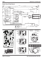
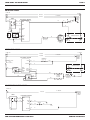
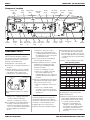
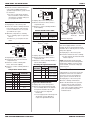
TECH SHEET - DO NOT DISCARD
WARNING
PAGE 1
DIAGNOSTIC GUIDE
DIAGNOSTIC TEST
Before servicing, check the following:
This diagnostic test allows factory/service
personnel to test and verify all inputs to the
electronic control. The basic operation of this
test is to notify the operator with an audible
beep every time the status of an input to the
control changes state.
Electrical Shock Hazard
Disconnect power before
servicing.
Replace all parts and panels
before operating.
Failure to do so can result in
death or electrical shock.
■ Make sure there is power at the wall
outlet.
■ Has a household fuse blown or circuit
breaker tripped? Time delay fuse?
■ Is dryer vent properly installed and
clear of lint or obstructions?
■ All tests/checks should be made with
a VOM (volt-ohm-milliammeter) or
DVM (digital-voltmeter) having a
sensitivity of 20,000 ohms per volt DC
or greater.
■ Check all connections before
IMPORTANT
replacing components. Look for
broken or loose wires, failed terminals,
or wires not pressed into connectors
far enough.
Electrostatic Discharge (ESD)
Sensitive Electronics
Do not open package until it is time to
install the electronic board.
■ A potential cause of a control not
functioning is corrosion on
connections. Observe connections
and check for continuity with an
ohmmeter.
ESD problems are present everywhere.
ESD may damage or weaken the
electronic board. The new board may
appear to work well after repair is
finished, but failure may occur at a later
date due to ESD stress.
■
■
■
■
Use an anti-static wrist strap. Connect
wrist strap to green ground connection
point or unpainted metal in the
appliance
-ORTouch your finger repeatedly to a green
ground connection point or unpainted
metal in the appliance.
Before removing the part from its
package, touch the anti-static bag to a
green ground connection point or
unpainted metal in the appliance.
Avoid touching electronic parts or
terminal contacts; handle electronic
board by edges only.
When repackaging failed electronic
board in anti-static bag, observe above
instructions.
■ Connectors: Look at top of connector.
Check for broken or loose wires.
Check for wires not pressed into
connector far enough to engage metal
barbs.
■ Resistance checks must be made with
dryer unplugged or power
disconnected.
LESS DRY TEST
This test is performed with a fully assembled
dryer, connected to a known good power
source.
Activating the Test Mode
1. Set the following configuration:
■
Door - must be open
■
Temperature switch - Air Only
■
End of Cycle Signal switch - Louder
■
Timer - Timed Drying or AccuDry
Sensor Drying selection
2. Turn the Wrinkle Shield switch from Off to
120 Minute three times within a five
second period. A single beep, a pause,
then a single beep will sound to indicate
that the test mode is activated.
NOTE: If any of these initial conditions are
not satisfied, the control will not enter the
test mode.
Test Mode Functionality
When the control is in test mode, every input
change of state will result in an audible beep
(with the exception of the End of Cycle Signal
switch). This includes:
■
Door switch
■
Moisture Sensor (short/open Sensor
will result in a beep)
Begin with a fully assembled, empty dryer
with clean lint screen. Be sure dryer is
connected to a known good power source.
NOTE: A moistened finger or damp
cloth may also be used.
1. Set the following configuration:
■
Temperature switch
■
Door - must be closed
■
Wrinkle Shield switch
■
Timer - Less Dry
■
■
Temperature switch - High
Push to Start (PTS) switch (with the
door switch closed)
■
End of Cycle Signal switch - Louder
■
Timer (any cam input change will result
in a beep)
2. Press the Push to Start (PTS) switch.
After approximately 16 seconds, the
Timer will start to advance to the Off
position. If this function does not occur,
proceed to the Diagnostic Test.
FOR SERVICE TECHNICIAN’S USE ONLY
NOTE: Timer will advance during test.
If any of the inputs do not result in a beep,
proceed to the corresponding component
tests, beginning on page 4.
PART NO. W10042930
PAGE 2
TECH SHEET - DO NOT DISCARD
Electric Dryer Wiring Diagram
L1 LINE – BK
R – LINE L2
240 VOLTS
120 VOLTS
DRUM LAMP
BK
DL
BK
R
BK
R
BU
TCO
310°F
(154°C)
PT-1
P1-1
V
P1-2
R
P1-3
W
BU
P1-4
TIMER
T2
MOIST.
T3
TEMP.
MODEL
T4
NEUTRAL
COM HEATER
RELAY
NO
BK
BU
NO
MOTOR
RELAY
COM
BU
BK
MOIST
GND
MTR
BU
PTS
DOOR
BU-BK
P3-1 48 VDC WSHIELD
R-W HEATER
HI
FS-1
R-W
HEATER
P3-2 LOW
FS-2
PK-BK
48 VDC
P2-7 MOTOR
PK-BK START
P1-5
START
SENSE
G
DOOR
SWITCH
R
G-Y
W
P2-4
Y-R
P2-3
R
P2-1
SENSOR
G-Y
W-R
THERMISTOR
10k Ω ± 3%
W
P3-8 GY 1
WRINKLE
SHIELD
W
5
P3-6 V
2
4
P3-5 OR 1
LOUD
P3-4 T-W 2
SOFT
1
P3-3
SIGNAL
CENTRIFUGAL SWITCH
MAIN
2.4–3.6
START
2.4–3.8
BU
BU
FABRIC
3
2M
5M
4
P3-7 T
FS-3
MODEL
MODEL
120 VAC RLY DR.
L1-RTN
BU
W
BU
BU
P2-6
P2-5
NEUTRAL
TERMINAL
LINKED TO
CABINET
W
ELECTRONIC CONTROL
TIMER
BK
R-W
W – NEUTRAL
OR
THERMAL FUSE
196 °F (91°C)
3M
1M
6M
DRIVE MOTOR
1/3 H.P.
4
R
W-BK
P4-4
P4-3
P4-2
P4-1
R-W
5400 WATT
2700 WATT
EACH LEG
R-W
BR
HEATER RELAY
BR
NC
BR
HIGH LIMIT
THERMOSTAT
180°F (82°C)
BR
AC COIL
7
PT-1
Blue
PinkBlack
Drum Size:
Drum Speed:
7 cubic feet
48 ± 3 RPM CW
Start Winding
Main Winding
PS02
4
PinkBlack
1
Blue
Black
Motor Relay
Red
PS03
8
Red-White
Red
5
RedWhite
1
1
RedWhite
PS01
Pluggable Drive Motor Switch
5
Red-White
D.C. Heater Relay
Timer
BU
BK
R
Wire Colors
Blue
Black
Red
PS04
V
W
Violet White
1
PT-1
Brown
B
U
DATE
4
Contacts
B
K
R
Brown
Electronic Control Assembly
Function
Violet White GreenYellow
Blue
W
V
1M 2M 3M 5M 6M
Brown
Start
Run
= Contacts closed
Centrifugal Switch (Motor)
PART NO. W10042930
Brown
A.C. Heater Relay
Timer
FOR SERVICE TECHNICIAN’S USE ONLY
TECH SHEET - DO NOT DISCARD
PAGE 3
MOTOR STRIP CIRCUIT
L1 LINE – BK
R – LINE L2
240 VOLTS
W – NEUTRAL
120 VOLTS
TIMER
ELECTRONIC CONTROL
BK
BK
PT-1
BU
TIMER
P1-1
DOOR
W
BU
P2-6
BU
NEUTRAL
TERMINAL
LINKED TO
CABINET
G
DOOR
SWITCH
MTR
W
BU
P3-2
HEATER
LOW
BU
BK
BU
NO
PTS
PK-BK
MOTOR
RELAY
MOTOR
START
PK-BK
BU
BU
BU
P1-5
BU-BK
BK
2M
5M
P2-7
COM
START
2.4–3.8 Ω
THERMAL FUSE
196 °F (91°C)
START
SENSE
CENTRIFUGAL SWITCH
MAIN
2.4–3.6 Ω
3M
1M
6M
DRIVE MOTOR
1/3 H.P.
BU
HEATER STRIP CIRCUIT
R – LINE L2
L1 LINE – BK
240 VOLTS
W – NEUTRAL
120 VOLTS
NEUTRAL
TERMINAL
LINKED TO
CABINET
ELECTRONIC CONTROL
TEMP.
THERMAL CUT-OFF
(TCO)
310 °F (154°C)
NEUTRAL
THERMISTOR
10k Ω ± 3%
P2-3
R
P2-1
W
W-R
2M
5M
CENTRIFUGAL SWITCH
R-W
COM
HEATER
RELAY
P3-1
R-W
P3-2
R-W
NO
48VDC
HEATER
HI
120VAC
RLY DR
P4-2
HEATER
LOW
L1-RTN
P4-1
3M
1M
6M
R/W
NC
HEATER RELAY
BR
5400 WATT
2700 WATT
EACH LEG
BR
BR
BR
AC COIL
R
HIGH LIMIT
THERMOSTAT
180°F (82°C)
MOISTURE SENSOR STRIP CIRCUIT
L1 LINE – BK
120 VOLTS
TIMER
BK
NEUTRAL
TERMINAL
LINKED TO
CABINET
ELECTRONIC CONTROL
BK
PT-1
BU
P1-1
TIMER
MTR
MOIST
GND
MOIST.
BU
W – NEUTRAL
NEUTRAL
P2-5
G-Y
P2-4
Y-R
P2-1
W
FOR SERVICE TECHNICIAN’S USE ONLY
SENSOR
G-Y
PART NO. W10042930
PAGE 4
TECH SHEET - DO NOT DISCARD
Component Location
Signal
Switch
Wrinkle Shield
Switch
Temperature
Switch
Ground
Screw
D.C. Heater
Relay Screws
(2)
Electronic
Control
Asm
D.C. Heater
Relay
5
PS01
1
1
5
PS03
8
1
PS02
4
7
Push To Start
(PTS)
Switch
PS04
4
End Cap
Screws
(2)
D.C.
Motor
Relay
D.C. Motor
Relay Screws
(2)
COMPONENT TESTS
Supply Connections Test
This test assumes that proper voltage is
present at the outlet, and visual inspection
indicates that the power cord is securely
fastened to the terminal block.
1. Unplug dryer or disconnect power.
2. Remove the cover plate from the back of
the dryer.
3. With an ohmmeter, check for continuity
between the neutral (N) terminal of the
plug and the center contact on the
terminal block. See illustration below.
N
Power Cord
Plug
L1
Terminal Block
A.C.
Heater
Relay
A.C. Heater
Relay Screws
(2)
Danger
Label
Control
Bracket
➔ When this is found, go to step 5.
➔ If neither of the plug terminals have
continuity with the left-most contact of
the terminal block, replace the power
cord and test the dryer.
5. Access the electronic control without
disconnecting any wiring to it.
Plug-to-terminal connections for electric
dryer.
➔ If there is no continuity, replace the
power cord and test the dryer.
➔ If there is continuity, go to step 4.
4. In a similar way, check which terminal of
the plug is connected to the left-most
contact on the terminal block and make
a note of it. This will be L1 (black wire) in
the wiring diagram. See illustration
above.
PART NO. W10042930
3. Check the timer motor resistance and
timer switching. The resistance (BU to
PT-1) should be 3 k ohms (±2). Use the
timer encoding table below for switching
conductivity, and refer to timer illustration
on page 2.
Timer
Contacts
➔ If there is continuity, go to step 7.
➔ If there is no continuity, check that
wires to the terminal block are
mechanically secure. If so, replace or
repair the main wire harness and test
the dryer.
7. Check for continuity between the neutral
(N) terminal of the plug and P2-1 (white
wire) on the electronic control.
➔ If there is no continuity and the
mechanical connections of the wire
are secure, replace or repair the main
wire harness.
TIMED DRYING MODE
Timed
Cool
Wrinkle
Drying
Down
Shield
W to BK
R to BK
V to BK
BU to BK
O
X
O
X
O
X
X
X
O
O
X
X
Off
O
O
O
O
ACCUDRY SENSOR DRYING MODE
Timer
Very
Energy
Less Wrinkle
Off
Contacts
Dry Preferred Dry
Shield
W to BK
R to BK
V to BK
BU to BK
X
O
X
X
O = OPEN
X
O
O
X
O
O
O
O
O
X
X
X
X = CLOSED
O
O
O
O
Motor Test
1. Unplug dryer or disconnect power.
2. Open the dryer door.
Timer Test
Perform the diagnostic test on page 1 to
determine that the timer motor advances
(should run continuously). If the timer does
not advance or fails the diagnostic test:
2. Remove the wires from timer terminals.
L.H.
End Cap
Timer Encoding Table
6. With an ohmmeter, check for continuity
between the L1 terminal of the plug
(found in step 4) and BK (black wire)
terminal on the timer.
1. Unplug dryer or disconnect power.
Timer
Timer Screws
(2)
Console
Panel
Reference contact continuity to timer - BK.
➔ If there is continuity, go to the Timer
Test.
COM
1
R.H.
End Cap
3. Measure resistance between the motor
relay common (COM) terminal and the
P2-6 terminal on the electronic control.
1 to 6 ohms should be measured.
➔ If resistance measurements are
outside 1 to 6 ohms, perform the
Thermal Fuse Test and Door Switch
Test, page 5; and check harness
continuity. If they test good, replace
the motor.
FOR SERVICE TECHNICIAN’S USE ONLY
TECH SHEET - DO NOT DISCARD
4. Measure resistance between the motor
relay common (COM) terminal and
ground. A high resistance (open) should
be measured.
PAGE 5
Wrinkle Shield Switch (On/Off) Test
Gray
1
➔ If it does not, perform the Thermal
Fuse Test and Door Switch Test and
check harness continuity. If they test
good, replace the motor.
4
WRINKLE
GUARD
White
Thermal
Cut-Off
1. Unplug dryer or disconnect power.
Door Switch Test
1. Unplug dryer or disconnect power.
2. Check door switch continuity. Neutral to
P2-6 on the electronic control should
read closed with the door closed, and
open with the door open.
3. Otherwise, verify harness continuity.
➔ If no continuity, repair or replace the
harness.
2. Remove the wires from the switch to
complete this test.
Thermal
Fuse
3. Reference contact continuity with Pin 1
to Pin 4 (White).
Wrinkle Shield Switch Table
SWITCH
POSITION
11 o’clock
CONTACTS
FUNCTION
Open
Wrinkle Shield Off
Wrinkle Shield
120 Minute
1 o’clock
Closed
➔ If harness is good, replace the door
switch.
Thermistor
High Limit
Thermostat
Heat
Element
Thermal Components.
End of Cycle Signal Switch Test
Temperature Switch Test
Orange
Violet
1
Tan
2
4
White-Black
Thermal Cut-Off Test
Tan-White
1
This unit is equipped with a “one-shot”
thermal cut-off. See Thermal Components
illustration above. If the dryer does not heat
with power supplied:
2
4
3
SIGNAL
5
White
1. Unplug dryer or disconnect power.
FABRIC
White
1. Unplug dryer or disconnect power.
1. Unplug dryer or disconnect power.
2. Remove the wires from the switch to
complete this test.
3. Reference contact continuity with
Pins 1 and 2 to Pin 4 (White).
2. Remove the wires from the switch to
complete this test.
3. Reference contact continuity with Pins 1
and 2 to Pin 4 (White).
End of Cycle Signal Switch Table
4. Reference contact continuity with Pin 3
to Pin 5.
SWITCH
POSITION
Temperature Switch Table
O
O
Off
FUNCTION
12 o’clock
X
O
Softer End of
Cycle Signal
O
Air Only, No Heat
2 o’clock
O
X
Louder End of
Cycle Signal
12 o’clock
O
O
2 o’clock
O
O
X
Ex-Low
4 o’clock
O
X
O
Low
5 o’clock
O
X
X
Medium, Casual
7 o’clock
X
O
O
High
8 o’clock
X
O
X
Normal
10 o’clock
X
X
O
Medium, Resource
Saver
X = CLOSED
O = OPEN
➔ If open, thermal cut-off has failed and
must be replaced.
NOTE: If the thermal cut-off has failed,
replace the thermal cut-off and high limit
thermostat. In addition, check for failed
heater element, or blocked or improper
exhaust system.
FUNCTION
10 o’clock
SWITCH CONTACTS
POSITION 3–5 2–4 1–4
O = OPEN
CONTACTS
1–4
2–4
2. Check the thermal cut-off for continuity.
X = CLOSED
High Limit Thermostat Test
1. Unplug dryer or disconnect power.
2. Remove the high limit thermostat and
check continuity. Refer to the Thermal
Components illustration above right.
➔ If open, replace the high limit
thermostat.
Thermal Fuse Test
A thermal fuse is used on this model. The
thermal fuse is wired in series with the
dryer drive motor. If the thermal fuse
opens, power is shut off to the motor.
1. Unplug dryer or disconnect power.
2. Check continuity of thermal fuse.
3. Once the thermal fuse has opened, it
must be replaced. Check for failed
thermistor, shorted heat element, or
other causes of failure. Replace failed
parts. See Thermal Components
illustration above.
➔ If closed, apply heat. It should open at
about 250°F (121°C). Otherwise,
replace the high limit thermostat.
FOR SERVICE TECHNICIAN’S USE ONLY
PART NO. W10042930
PAGE 6
TECH SHEET - DO NOT DISCARD
Thermistor Test or Dryer Beeps
3 Times when Push to Start (PTS)
Pressed
An electronic temperature sensor called a
thermistor is used in this model in place of
an operating thermostat. The electronic
control monitors the exhaust temperature
using the thermistor, and cycles the heater
relay on and off to maintain the desired
temperature.
Procedure
Begin with a fully assembled, empty dryer
and a clean lint screen.
■
➔ If the dryer appears to operate
correctly, proceed to step 3.
3. Remove exhaust vent and start the dryer.
➔ Turn Temperature switch to desired
temperature to be tested, and select
20 minutes of Timed Drying. Hold a
glass bulb thermometer capable of
reading from 90°F to 180°F (32°C to
82°C) in the center of the exhaust
outlet. Measure exhaust temperatures
with heater off and on.
The correct exhaust temperatures
are as follows:
1. Set the following configuration:
■
Door - must be closed
■
Timer dial - Timed Drying
■
Temperature switch - High
■
Wrinkle Shield switch - Off
■
End of Cycle Signal switch - Louder
2. Press the Push to Start switch.
➔ If you hear three short beeps and the
dryer shuts off after several seconds,
the thermistor or wire harness is either
shorted or open.
■
Unplug dryer or disconnect power.
■
Check wire connections at the
electronic control and thermistor.
EXHAUST TEMPERATURES
TEMPERATURE HEAT TURNS HEAT TURNS
SWITCH
OFF*
ON
SETTING
°F (°C)
°F (°C)
155° ± 10°
High
(68° ± 6°)
Normal
145° ± 10°
(63° ± 6°)
Medium, Casual
10°–15° (6°–8°)
below the
Medium,
135° ± 10°
heat turn off
Resource Saver
(57° ± 6°)
temperature
125° ± 10°
Low
(52° ± 6°)
115° ± 10°
Ex-Low
(46° ± 6°)
Unplug dryer or disconnect power.
■
Disconnect wires from thermistor,
then check the resistance of the
thermistor. The following table
gives temperatures and ranges for
their associated resistance values:
THERMISTOR RESISTANCE
TEMP.
°F (°C)
RES.
kΩ
TEMP.
°F (°C)
RES.
kΩ
50° (10°)
19.0–22.0
80° (27°)
8.5–10.5
60° (16°)
14.8–16.8
90° (32°)
6.8–8.8
70° (21°)
11.5–13.5
100° (38°)
5.0–7.0
➔ If the thermistor resistance does not
agree with table, replace the
thermistor.
➔ If the thermistor resistance checks
agree with the measurements in the
table, replace the electronic control
assembly.
bulb thermometer in the exhaust outlet
can be 30°F (17°C) higher.
IMPORTANT: Electrostatic (static electricity) discharge may cause damage to
electronic control assemblies. See page 1 for details.
POSSIBLE CAUSE / TEST
Refer to Motor Strip Circuit, page 3.
– SUPPLY CONNECTIONS
– HARNESS/CONNECTION
– MOTOR RELAY
DRYER WILL NOT – PUSH TO START (PTS) SWITCH
RUN.
– THERMAL FUSE
– MOTOR
– DOOR SWITCH
– ELECTRONIC CONTROL
For more details, see Troubleshooting section, page 7.
Refer to Heater Strip Circuit, page 3.
– SUPPLY CONNECTIONS
– HARNESS/CONNECTION
– HEATER RELAY
– THERMAL CUT-OFF
DRYER WILL NOT – THERMAL FUSE
HEAT.
– HIGH LIMIT THERMOSTAT
– HEATER
– CENTRIFUGAL SWITCH
– THERMISTOR
– ELECTRONIC CONTROL
For more details, see Troubleshooting section, page 7.
Refer to Heater Strip Circuit, page 3.
– HARNESS/CONNECTION
DRYER HEATS
– HEATER RELAY
DURING AIR
ONLY (NO HEAT) – TEMPERATURE SWITCH
CYCLE.
– ELECTRONIC CONTROL
For more details, see Troubleshooting section, page 7.
PART NO. W10042930
■
* The measured overshoot using the glass
TROUBLESHOOTING GUIDE
PROBLEM
➔ If the exhaust temperature is not
within specified limits:
If wiring is functional, replace the
thermistor. Refer to Thermal
Components illustration, page 5.
PROBLEM
DRYER WON’T
SHUT OFF.
DRYER SHUTS
OFF BEFORE
CLOTHES
ARE DRY.
TIMER
CONTINUOUSLY
ADVANCES.
POSSIBLE CAUSE / TEST
Refer to Motor and Moisture Sensor Strip Circuits,
page 3.
– PUSH TO START (PTS) SWITCH
– HARNESS/CONNECTION
– MOTOR RELAY
– MOISTURE SENSOR
– ELECTRONIC CONTROL
For more details, see Troubleshooting section, page 7.
Refer to Thermistor Test, this page; and Moisture
Sensor Strip Circuit, page 3.
– HARNESS/CONNECTION
– MOISTURE SENSOR
– THERMISTOR
– ELECTRONIC CONTROL
– MAY NEED TO CHANGE TIMER SETTING TO A MORE DRY
SETTING
For more details, see Troubleshooting section, page 8.
Refer to Timer Drawing, page 2; and Motor Strip
Circuit, page 3.
– HARNESS/CONNECTION
– TIMER
For more details, see Troubleshooting section, page 8.
WRINKLE SHIELD
DOES NOT RUN. Refer to Wrinkle Shield Switch (On/Off) Test, page 5.
FOR SERVICE TECHNICIAN’S USE ONLY
TECH SHEET - DO NOT DISCARD
PAGE 7
TROUBLESHOOTING
IMPORTANT: Electrostatic (static electricity) discharge may cause damage to
electronic control assemblies. See page 1 for details.
PROBLEM: Dryer Will Not Run
PROBLEM: Dryer Won’t Shut
Off
(Refer to Motor Strip Circuit, page 3; and
Troubleshooting Guide, page 6.)
1. Unplug dryer or disconnect power.
(Refer to Motor and Moisture Sensor Strip
Circuits, page 3; and Troubleshooting
Guide, page 6.)
1. With the dryer fully assembled, set the
timer to Off. If the dryer starts running as
soon as it is plugged in:
2. Check connector pins in P2 connector of
the electronic control to verify they are
making good connections.
3. Check the Push to Start (PTS) switch
continuity when pressed. It should show
continuity while pushed in. If not, replace
the PTS switch.
➔ Unplug dryer or disconnect power.
➔ Replace the timer.
2. Set the following configuration:
4. Perform Thermal Fuse Test, page 5.
5. Perform Door Switch Test, page 5.
Actuator in off condition.
6. If the motor started but did not continue
to run, and components checked in
steps 2 through 5 were OK, replace the
electronic control assembly.
■
Dryer - power cord plugged in
■
Door - must be closed
■
Temperature switch - High
■
Timer - Timed Drying for less than
10 minutes
3. If the dryer starts running before the
Push to Start (PTS) switch is pressed:
7. If motor did not start and components
checked in steps 2 through 5 were OK,
replace the motor.
➔ Unplug dryer or disconnect power.
➔ Replace the PTS switch.
PROBLEM: Dryer Will Not Heat
➔ If, after replacing the PTS switch, the
dryer still starts before the PTS switch
is pressed:
(Refer to Heater Strip Circuit, page 3; and
Troubleshooting Guide, page 6.)
1. Perform Supply Connections Test,
page 4.
➔ Unplug dryer or disconnect power.
➔ Replace the motor relay.
2. Perform Thermal Cut-Off Test, page 5.
3. Perform High Limit Thermostat Test,
page 5.
Actuator in run position.
4. Unplug dryer or disconnect power.
5. Check continuity of heater:
➔ Each element should be about 20
ohms and should be open to ground,
chassis, and neutral.
➔ If either element fails these tests in
step 5, replace the heat element
assembly.
6. Check continuity of motor centrifugal
switch:
➔ 1M to 2M terminals should be open in
the off condition. Manually operating
the switch should close 1M to 2M.
This can be done by pushing the
actuator from the off condition to the
run position. See the illustration
above right.
PROBLEM: Dryer Heats During
Air Only (No Heat) Cycle
(Refer to Heater Strip Circuit, page 3; and
Troubleshooting Guide, page 6.)
1. Perform Temperature Switch Test, page 5.
2. Unplug dryer or disconnect power.
3. Check continuity of heater relay
contacts. COM to NO should be open.
If not, replace the heater relay.
4. With dryer fully assembled, plug in dryer
or reconnect power.
5. Set to Air Only. If the dryer still heats:
➔ If these conditions are not true,
replace the motor.
FOR SERVICE TECHNICIAN’S USE ONLY
➔ Unplug dryer or disconnect power.
➔ Replace the electronic control
assembly.
4. If the dryer does not stop after the set
time elapses:
➔ Unplug dryer or disconnect power.
➔ Check the motor relay. Continuity of
relay should be open from COM to
NO.
5. If the dryer will not terminate its cycle
when set to AccuDry Sensor Drying:
➔ Unplug dryer or disconnect power.
➔ Check the moisture sensor.
➔ If there is continuity to Ground for
Yellow-Red (Y-R) wire with no load,
look for a short in the sensor or Y-R
wire. Verify harness connections both
at the sensor and the electronic
control.
➔ If the sensor and Y-R wire are good,
replace the electronic control
assembly.
PART NO. W10042930
PAGE 8
TROUBLESHOOTING (cont.)
TECH SHEET - DO NOT DISCARD
IMPORTANT: Electrostatic (static electricity) discharge may cause damage to
electronic control assemblies. See page 1 for details.
PROBLEM: Dryer Shuts Off
Before Clothes Are Dry
PROBLEM: Timer Continuously
Advances
(Refer to Moisture Sensor Strip Circuit,
page 3; Thermistor Test, page 6; and
Troubleshooting Guide, page 6.)
1. Test the moisture sensor by following the
procedure outlined in the Diagnostic
Test, page 1. If the moisture sensor fails
the Diagnostic Test (does not produce a
beep sound):
(Refer to Timer Drawing, page 2; Motor
Strip Circuit, page 3; and Troubleshooting
Guide, page 6.)
1. Unplug dryer or disconnect power.
➔ Unplug dryer or disconnect power.
➔ Check the moisture sensor.
➔ If there is continuity to Ground for
Yellow-Red (Y-R) wire with no load,
look for a short in the Sensor or Y-R
wire. Verify harness connections both
at the sensor and the electronic
control.
2. Verify the Blue wire and the Black L1
wires are in the correct positions. See
timer illustration on page 2.
3. Test the timer by following the procedure
outlined in the Diagnostic Test, page 1.
4. If the timer continues to advance past
Off, replace the timer.
➔ If the sensor and Y-R wire are good,
replace the electronic control
assembly.
2. If Diagnostic Test is passed, verify
thermistor by performing test procedures
outlined in Thermistor Test, page 6.
3. If problem persists after replacing
moisture sensor and thermistor:
➔ Unplug dryer or disconnect power.
➔ Replace the electronic control
assembly.
MANUFACTURED UNDER ONE OR MORE
OF THE FOLLOWING U.S. PATENTS:
4,669,200
4,700,495
4,754,556
4,840,285
4,865,366
4,899,464
4,908,959
PART NO. W10042930
4,989,347
5,066,050
5,560,120
5,809,828
6,020,698
6,047,486
6,199,300
6,446,357
6,597,144
6,604,298
6,685,241
6,732,447
6,784,673
6,819,255
D,314,261
D,314,262
D,457,991
D,457,992
D,495,453
FOR SERVICE TECHNICIAN’S USE ONLY
03/06