1
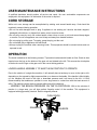
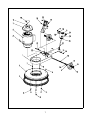
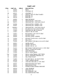
Front Runner
Floor Machines
Model:
FR17115, FR17220, FR17220-60
FR20115, FR20220, FR20220-60
FR20115-2S, FR20220-2S
OPERATION
Revised 08/2010
SERVICE
PARTS
CARE
FOR COMMERCIAL USE ONLY
IMPORTANT SAFETY INSTRUCTIONS
When using an electrical appliance, basic precautions should always be followed, including the following:
READ ALL INSTRUCTIONS BEFORE USING
WARNING - To reduce the risk of fire, electric shock, or injury:
•
Do not leave appliance when plugged in. Unplug from outlet when not in use and before servicing.
WARNING
To reduce the risk of electrical shock - Do not expose to rain. Store indoors.
• Never allow children or untrained adults to operate this equipment.
• Keep the area of operation clear of all persons, particularly small children, and pets. Keep bystanders
at least 25 feet away from the area of operation.
• Use only as described in this manual. Use only manufacturer‘s recommended attachments.
• Do not use with damaged cord or plug. If appliance is not working as it should, has been dropped,
damaged, left outdoors, or dropped into water, return it to a service center.
• Do not pull or carry by cord, use cord as a handle, close a door on cord, or pull cord around sharp
edges or corners. Do not run appliance over cord. Keep cord away from heated surfaces.
• Do not unplug by pulling on cord. To unplug, grasp the plug, not the cord.
• Do not handle plug or appliance with wet hands.
• Do not put any object into openings. Do not use with any opening blocked; keep free of dust, lint, hair,
and anything that may reduce air flow.
• Keep hair, loose clothing, fingers, and all parts of body away from openings and moving parts.
• Turn off all controls before unplugging.
• Connect to a properly grounded outlet only. See grounding instructions.
SAVE THESE INSTRUCTIONS
1
INSPECTION
Carefully unpack and inspect your machine for shipping damage. Each unit is tested and thoroughly inspected
before shipment, and any damage is the responsibility of the delivery carrier who should be notified
immediately.
WARNING
Read Instruction Manual before operating this piece of equipment.
• To reduce the risk of fire use only commercially available floor cleaners and waxes intended for machine
application.
• Risk of explosion - floor sanding can result in an explosive mixture of fine dust and air. Use floor sanding
machine in a well-ventilated area free from any flame or match.
• Electrical motors and components can cause an explosion when operated near volatile materials and
vapors. Do not use this machine near flammable materials such as solvents, thinners, fuels, grain dust, etc.
ELECTRICAL - 115 Volt
Model FR17115, FR20115, FR20115-2S
This machine is designed to operate on a standard 15 amp. 120 volt, 60 Hz, AC circuit. Voltages below 105
volt AC or above 125 volts AC could cause serious damage to the motor.
ELECTRICAL - 240 Volt
Model FR17220, FR20220, FR20220-2S, FR17220-60(*), FR20220-60(*)
This machine is designed to operate on a standard 8.3 amp type L fused 230 volt, 50 Hz (* implies 60 Hz), AC
circuit. Voltages below 200 volt AC or above 250 volts AC could cause serious damage to the motor.
GROUNDING INSTRUCTIONS
• This floor finishing machine should be grounded while in use to protect the operator from electric shock. The
machine is equipped with a three-conductor cord and a three-prong grounding type attachment plug to fit the
proper grounding type receptacle. The green (or green and yellow) conductor in the cord is the grounding
wire. Never connect this wire to other than the grounding blade.
• Floor Finishing Machines Rated Less Than 150 Volts - If the machine is provided with an attachment plug as
shown in Sketch A it is intended for use on a 120-volt (nominal) circuit.
• If a properly grounded receptacle as shown in Sketch A is not available, an adapter as shown in Sketch C is
available and should be installed as shown in Sketch B if the outlet box that houses the receptacle is
grounded. Be sure to fasten the grounding tab with the faceplate screw.
• Floor Finishing Machines Rated More Than 150 Volts - If the machine is provided with an attachment plug
as shown in Sketch D, it is intended for use on a nominal 240 volt circuit. No adapter is available for this
plug.
2
POUR USAGE COMMERCIAL SEULEMENT
MODE D’EMPLOI SECURITAIRE
Lorsque l’on utilise un appareil électrique, des précautions de base doivent toujours être suivies telles
que:
BIEN LIRE LE MODES D’EMPLOI AVANT USAGE
AVERTISSEMENT
- Pour réduire les risques de feu, choc électrique ou blessure:
Ne pas quitter l’appareil lorsque la prise de courant est branchée. Débrancher de la sortie électrique
lorsque la machine n’est pas en usage ou pour en faire le service.
AVERTISSEMENT
- Pour réduire le risque de choc électrique - Ne pas exposer à la
pluie – Entreposer à l’intérieur.
• Ne pas permettre l’usage comme jouet. Etre très prudent lorsque l’appareil est utilisé en présence
d‘enfants.
• Utiliser tel que prescrit dans le livre d’opération et seulement avec les attachements recommandés par
le manufacturier.
• Ne pas s’en servir avec corde ou prise de courant endommagée. Si l’appareil ne fonctionne pas ou a
été échappé, endommagé, entreposé à l’extérieur ou dépose dans l’eau, l’appareil devrait être envoyé
à un département de service pour inspection.
• Ne pas tirer ou porter par le câble ou se servir du câble comme poignée. Ne pas fermer de portes sur
le câble ou tirer le câble près d’objets pointus. Ne pas conduire l’appareil en écrasant le câble et soyez
certain de protéger le câble entre toutes surfaces de chauffage.
• Ne pas débrancher en se servant du câble. Pour débrancher tirer sur la prise et non sur le câble.
• Ne pas manipuler la prise ou l’appareil avec les mains mouillées.
• Ne placer aucun objet dans la sortie et ne pas s’en servir si la sortie est obstruée. Eliminer toute
poussière, maillon, cheveux ou quoique ce soit qui pourrait réduire le mouvement d’air.
• N’exposer aucuns cheveux, vêtement, doigts ou autres aux ouvertures de l’appareil.
• Fermer tous les contrôles après utilisation.
• Brancher dans une prise avec une prise de terre seulement. Voir références pour prise de terre.
CONSERVEZ CES RECOMMANDATIONS
DE MODE D’EMPLOI
3
INSPECTION
Déballer soigneusement en constatant s’il y, a lieu tout dommage apparent. Chacune des pièces
d’équipement est entièrement inspectée à l’usine et tout dommage de transit est la responsabilité de la
compagnie de transport qui devrait être prévenue immédiatement.
AVERTISSEMENT
• S. V. P. lire le manuel d’instruction avant d’opérer cette pièce d’équipement.
• Pour réduire le risque d’incendie, se servir de ces appareils uniquement pour usage commercial et
avec les produits construits spécifiquement pour usage avec ces appareils.
• Les moteurs électriques peuvent être la cause d’explosion s’ils sont utilisés près de matériaux ou de
vapeurs explosives. Ne pas opérer près de matériaux inflammables tells que solvant, essence,
poussière de grain etc.
ELECRICITE - 115 Volt
Modèles FR17115, FR20115, FR20115-2S
Ces appareils sont congrus pour opérer sur un circuit standard de 15 amp 120 volt, 60 hz, circuit AC.
Tout voltage en bas de 105 volt AC ou au-delà de 125 volts AC pourrait occasionner des dommages au
moteur.
ELECRICITE - 240 Volt
Modèles FR17220, FR20220, FR20220-2S, FR17220-60(*), FR20220-60(*)
Ces appareils sont congrus pour opérer sur un circuit standard AC de 8.3 amp fusible type L230 volt,
50 Hz (* 60 Hz). Tout voltage en bas de 200 volt AC ou au-delà de 250 volts AC pourrait occasionner
des dommages au moteur.
INSTRUCTION POUR PRISE DE TERRE
• Ces appareils doivent posséder une prise de miss à terre pour protéger I’opérateur contre les chocs
électriques. Cet appareil est muni d’une corde électrique à trois fils et d’un réceptacle à trois fourchons
et prise de mise à terre pour s’accorder dans un réceptacle avec prise de mise à terre réciproque. Le
fil conducteur vert (ou vert et jaune) de la corde électrique est le fil désigné comme prise de mise à
terra. Ne jamais relier ce fil à un fil autre que celui de prise de mise à terre.
• Appareils estimés à moins de 150 volts. - Si ces appareils offrent une prise de courant tel que dans le
croquis A, ils sont destinés pour utilisation avec un circuit de 120 volts. Si un réceptacle avec prise de
mise à terre n’est pas disponible tel que montré au croquis A, un adapteur tel que vu au croquis C est
disponible et devrait être installé tel que montré au croquis B si la boite électrique est munie d’une
prise de mise à terre. Assurez-vous de bien relier la patte de prise avec la vis.
• Appareils destinés à plus de 150 volts. - Si ces appareils offrent une prise de courant tel que démontré
au croquis D, ils doivent être utilisés avec un circuit de 240 volts. Aucun adapteur n’est disponible pour
cette prise.
4
USER MAINTENANCE INSTRUCTIONS
A qualified electrician should perform all service and repair. No user serviceable components are
employed in this equipment. No lubrication of the motor is required.
CORD STORAGE
While not in use, storage can be accomplished by winding cord around handle assy. Cord should be
completely unwound during operation.
• Do not use with damaged cord or plug. If appliance is not working as it should, has been dropped,
damaged, left outdoors, or dropped into water, return to service center.
• Do not pull or carry by cord, use cord as handle, close a door on cord, or pull cord around sharp edges
or corners. Do not run appliance over cord. Keep cord away from heated surfaces.
• Do not unplug by pulling cord. To unplug, grasp the plug, not the cord.
• Do not handle plug or appliance with wet hands.
• Always unplug the machine when removing brush. This equipment should be stored indoors and not
exposed to rain.
OPERATION
The brush is attached in the following manner: Tip machine backward with handle on floor. Brush is then
inserted over the lugs on the bottom of the gear unit and twisted to the left. This secures the clutch plate
of the brush over the lugs on the gear unit in the correct driving position.
LOWER HANDLE ASSEMBLY TO WAIST HIGH POSITION TO OPERATE.
Due to the rotation of a single disc machine, it will naturally have a tendency to move to the right or left,
depending on the operator’s slight pressure either up or down on the handle. If the handle is lifted slightly
up, the machine will travel to the right; a downward pressure and it will travel to the left. It is this
maneuverability that enables an operator to cover large areas in a short time with the least amount of
effort. The machine can be made to operate without travel by balancing…
... KEEPING THE BRUSH PRESSURE ON THE FLOOR EQUAL. With a few minutes of
practice in a large area, you will have perfect fingertip control of the machine. This equipment is
equipped with trigger safety interlock. Refer to diagram pictured.
PUSH DOWN
SQUEEZE
SQUEEZE
5
WIRING DIAGRAM
6
7
PART LIST
ITEM
1
2
2A
3
4
4A
5
6
6A
6B
6C
6D
7
8
9
10
11
11A
12
13
14
15
16
17
18
19
20
21
21A
22
23
24
25
26
27
28
29
30
31
32
33
PART NO.
195000
195020
195017
714203
195021
195018
195006
200025
750571
740286
740287
200025-1
713175
714204
714201
714001
195004
195008
710354
195005
714150
195001
195003
195002
714151
715459
714205
715382
715383
715062
195039
714000
195038
714100
195037
195031
195033
195034
195032
195036
195035
REQ’D
1
1
1
6
1
1
2
1
1
1
1
1
4
4
4
4
1
1
3
1
6
1
2
2
2
1
2
1
1
1
1
2
1
2
1
1
1
2
1
1
1
DESCRIPTION
BASE
HOUSING, 20”
HOUSING, 17”
WSR-FLT M14 STL ZINC SILVER
BUMPER, 20”
BUMPER, 17”
SNAP BUSHING
GEAR MOTOR, 1.5 HP, 120V
GEAR MOTOR, 1.5 HP, 240V, 50 HZ
GEAR MOTOR, 2 SPEED, 120V
GEAR MOTOR, 2 SPEED, 240V
GEAR MOTOR, 1.5 HP, 240V, 60 HZ
SC-SHCS 5/16-18 X 2.25 STL ZINC
WSR-HELICAL M8 STL BLACK
WSR-FLT M8 STL ZINC
BLT-HH M8 X 1.25 X 25 STL ZINC
MOTOR COVER
MOTOR COVER, 2 SPEED
SCR-MC TR HD 10-32 X .50 STL ZINC
PIN, PIVOT
RET RING-E TYPE M8 X 16 X 0.9 STL ZINC
WHEEL SHAFT
WHEEL CAP ASSY
WHEEL, 5.00 X 1 1/4
RET RING-E TYPE M12 X 24 X 1.2 STL ZINC
DECAL, FR MOTOR COVER
WSR-WAVE M14
DECAL, MINUTEMAN
DECAL, MINUTEMAN, LIGHT GRAY
DECAL, WARNING GENERAL FM
PIN, FRONT PIVOT
SC-SHCS M6 X 1.0 X 25 STL ZINC
YOKE, HANDLE MOUNT
LOCK NUT-HEX M6 X 1.0 STL ZINC
RELEASE ROD PIVOT ASSY
RELEASE BOTTOM
SPRING-COMP, HANDLE RELEASE
LINK, RELEASE
RELEASE TOP
PIN, RELEASE, TOP
PIN, RELEASE BOTTOM
8
9
PART LIST
ITEM
1
2
3
4
5
6
7
8
9
10
11
12
13
13A
14
14A
15
16
17
18
19
20
20A
21
22
23
24
25
26
27
28
29
30
31
34
34A
35
PART NO.
195050
195051
195053
195070
195054
195071
195055
195075
195074
195052
714202
740036-3
195058
195059
195056
195057
195060
195072
714050
715175
741502
150002
740600
741503
195073
714051
197077
741504
714200
195076
195061
714206
714100
714000
740238
741400
741507
REQ’D
1
1
2
2
1
1
1
1
1
1
1
1
1
1
2
2
1
2
14
1
1
1
1
1
1
3
2
1
1
1
1
3
1
1
1
1
2
DESCRIPTION
HANDLE FRONT
HANDLE REAR
SWITCH TRIGGER
PIN, TRIGGER PIVOT
RELEASE LEVER
PIN, RELEASE LEVER PIVOT
SAFETY BUTTON
RELEASE ROD, HANDLE
HANDLE TUBE
SWITCH COVER
WSR-FLT M13 X 37 X 3, ZTL ZINC
TERMINAL BLOCK, 3 POLE
STRAIN RELIEF, RUBBER, 120V
STRAIN RELIEF, RUBBER, 240V
STRAIN RELIEF, PLASTIC, 120V
STRAIN RELIEF, PLASTIC, 240V
CORD HOOK ASSY
STEEL BALL, SAFETY BUTTON
SCR-ST M4.8 X 25 STL ZINC
DECAL, MINUTEMAN RUNNER
SWITCH, PUSHBUTTON
CORD SET, 14-3 STW X 50’ (120V)
CORD SET, 16-3 SJT X 50’ (240V)
CORD SET,HANDLE,14-3 SJT X 43"
SPRING-COMP, SAFETY BUTTON
SCR- ST M4.2 X 30 (F) STL ZINC
CLAMP, HANDLE CORD
WIRE-14G WHITE 4.72"
WSR-FLT M6 STL ZINC SILVER
SPRING-COMP, RELEASE ROD
GUIDE, RELEASE ROD
WSR-FLT M5 STL ZINC
LOCK NUT-HEX M6 X 1.0 STL ZINC
SC-SHCS M6 X 1.0 X 25 STL ZINC
CIRCUIT BREAKER, 120V – 18A
CIRCUIT BREAKER, 240V – 10A
WIRE-14G BLACK 4.72" WITH TERMINAL
10
Minuteman International Made Simple Commercial Limited Warranty
REVISION F
EFFECTIVE 6/1/2009
Minuteman International, Inc. warrants to the original purchaser/user that the product is free from defects in workmanship and
materials under normal use. Minuteman will, at its option, repair or replace without charge, parts that fail under normal use and
service when operated and maintained in accordance with the applicable operation and instruction manuals. All warranty
claims must be submitted through and approved by factory authorized repair stations.
This warranty does not apply to normal wear, or to items whose life is dependent on their use and care, such as belts, cords,
switches, hoses, rubber parts, electrical motor components or adjustments. Parts manufactured by Minuteman are covered by
and subject to the warranties and/or guarantees of their manufacturers. Please contact Minuteman for procedures in warranty
claims against these manufacturers.
Special warning to purchaser — Use of replacement filters and/or prefilters not manufactured by Minuteman or its designated
licensees, will void all warranties expressed or implied. A potential health hazard exists without original equipment
replacement.
All warranted items become the sole property of Minuteman or its original manufacturer, whichever the case may be.
Minuteman disclaims any implied warranty, including the warranty of merchantability and the warranty of fitness for a particular
purpose. Minuteman assumes no responsibility for any special, incidental or consequential damages.
This limited warranty is applicable only in the U.S.A. and Canada, and is extended only to the original user/purchaser of this
product. Customers outside the U.S.A. and Canada should contact their local distributor for export warranty policies.
Minuteman is not responsible for costs or repairs performed by persons other than those specifically authorized by Minuteman.
This warranty does not apply to damage from transportation, alterations by unauthorized persons, misuse or abuse of the
equipment, use of non-compatible chemicals, or damage to property, or loss of income due to malfunctions of the product.
If a difficulty develops with this machine, you should contact the dealer from whom it was purchased.
This warranty gives you specific legal rights, and you may have other rights which vary from state to state. Some states do not
allow the exclusion or limitation of special, incidental or consequential damages, or limitations on how long an implied warranty
lasts, so the above exclusions and limitations may not apply to you.
Cord Electric Group: Three years parts, two years labor, ninety days travel (Not to exceed two hours)
Exceptions……….
Model
Parts
Labor
Poly
Travel
Port A Scrub
MPV 13
MPV 14 & 18
V Series Upright Vacuums
Rapid Air Blower
Explosion Proof Vacuum
X12, X12H & TRS 14
E17 & E20 Electric Scrubbers
Pneumatic Vacuums
1 yr
1 yr
2 yrs
1 yr
1 yr
1 yr
1 yr
1 yr
3 yr
6 months
0
1 yr
1yr
1 yr
1 yr
1 yr
6 months
1 yr
10 yrs
0
0
0
10 yrs
0
10 yrs
10 yrs
0
0
0
0
0
0
0
0
0
Description
Parts
0
Labor
Poly
Travel
Battery Operated Group
Sweepers
Internal Combustion Group
3 yrs
1 yr
1 yr
2 yrs
1 yr
1 yr
10
10
10
Exception: PAS 14B
1 yr
1 yr
10 yr
90 days
90 days
90 days
Not to exceed two hours
0
Battery Chargers:
Replacement Parts:
Batteries:
Polyethylene Plastic Tanks:
One year replacement
Ninety days
0-3 months replacement, 4-12 months pro-rate
Tanks have 10yr warranty, no additional labor
988344
REV F 08/10
14N845 U.S. Route 20 · Pingree Grove, Illinois 60140 USA
Phone: (847) 683-5210 · Fax (847) 683-5207
www.minutemanintl.com
A Member of the Hako Group