1
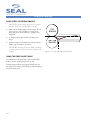
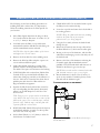
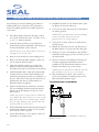
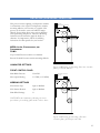
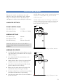
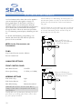
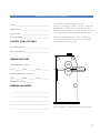
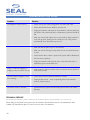
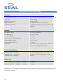
Image® 600-C Laminator Owner’s Operation Manual Image ® 600-C Laminator TABLE OF CONTENTS TABLE OF CONTENTS ...................................................................................................................................................................2 INTRODUCTION................................................................................................................................................................................3 WORKSPACE / ELECTRICAL REQUIREMENTS .............................................................................................................4 ENVIRONMENT CONDITIONS................................................................................................................................................5 UNPACKING, SET-UP AND INSTALLATION....................................................................................................................6 UNPACKING, SET-UP AND INSTALLATION....................................................................................................................7 IMPORTANT SAFEGUARDS.........................................................................................................................................................8 SAFETY FEATURES ...........................................................................................................................................................................9 LAMINATOR FEATURES................................................................................................................................................................10 FRONT CONTROL PANEL ...........................................................................................................................................................11 CHECKING OPERATION..............................................................................................................................................................12 SET-UP AND OPERATION............................................................................................................................................................13 SET-UP AND OPERATION............................................................................................................................................................14 SET-UP AND OPERATION............................................................................................................................................................15 FEEDING IMAGES............................................................................................................................................................................16 WEBBING FILMS WITH A RELEASE LINER (NORTH AMERICA) .........................................................................17 WEBBING FILMS WITH A RELEASE LINER (EUROPE & ASIA)..............................................................................18 DECALING (PRESSURE- SENSITIVE).....................................................................................................................................19 MOUNTING...........................................................................................................................................................................................20 PRE-COATING BOARDS................................................................................................................................................................21 APPLYING AN OVER-LAMINATE ...........................................................................................................................................22 GLOSSARY OF TERMS.....................................................................................................................................................................23 PROCESS APPLICATION NOTES ..............................................................................................................................................24 PROCESS CONTROL SHEET........................................................................................................................................................25 CLEANING / MAINTAINING YOUR LAMINATOR......................................................................................................26 PERIODIC MAINTENANCE SHEET........................................................................................................................................27 TROUBLESHOOTING GUIDE....................................................................................................................................................28 SPARE PARTS LIST..............................................................................................................................................................................29 TECHNICAL SPECIFICATIONS..................................................................................................................................................30 LIMITED WARRANTY......................................................................................................................................................................31 2 INTRODUCTION Thank you for purchasing a SEAL ® Image® 600-C Laminator. We have designed the SEAL Image 600-C to give you years of reliable service. As you become familiar with your laminator, you will appreciate the high quality of its production and the excellence in its engineering design. By following the guidelines for proper care and use of the laminator, you can depend on many years of trouble-free profitability from your investment. The purpose of this manual is to outline the materials and process when using SEAL Brands supplies with your laminator to create signs, displays, and flexible graphics with professional results. The manual includes instructions of various laminating procedures, which are meant to give you comprehensive information needed for the efficient use of your laminator. Please read and fully understand the entire manual before proceeding to use your laminator. STATEMENT OF INTENDED USE Your SEAL Image 600-C Laminator meets the CE Machinery Safety Directive and is ETL approved. The SEAL Image 600-C laminator has been designed to be used with SEAL Brands materials. When used with these products, you are able to mount, mount and laminate, and encapsulate prints. Your laminator has been tested with SEAL Brands supplies and we recommend using these products for professional results. WARNING! This laminator is designed for mounting and laminating. Any use other than the intended may cause damage to the laminator or physical harm to the user. WARNING! Any unauthorized changes or modifications to this unit without our prior written approval will void the user’s warranty and will transfer health and safety obligations to the user. LIABILITY STATEMENT The details given in this manual are based on the most recent information available to us. They may be subject to change in the future. We retain the right to make changes to the construction or the design of our products without accepting any responsibility for modifying earlier versions previously delivered. CAUTION! Please pay attention to all passages marked this way. This information is vital to preventing user injury and/or damage to the unit. Failure to follow this information could void the user’s warranties and transfer all safety obligations to the user. 3 WORKSPACE / ELECTRICAL REQUIREMENTS • • Keep the area around your laminator clear with adequate space around it so you can feed, receive and trim mounted and/or laminated images. CONNECTING YOUR LAMINATOR Connect the laminator in accordance with the details given on the identification plate attached to the rear of the laminator. Refer also to the Technical Specifications page for more information. An area 15’ x 11’ (4.5m x 3.4m) is the smallest area recommended. We recommend a room size of 20’x 18’ (6.1m x 5.49m) to accommodate a laminator and 2 (4’ x 8’) tables on castors for finishing/layout work. This area is required for loading and unloading rolls of material onto the unwind shafts and feeding and receiving the maximum mounting board lengths into the laminator correctly. • NOTE: Maximum board lengths are up to 12 feet long. • The work area should be level, flat, and well lit. IMPORTANT! SEAL recommends that a licensed electrician in accordance with electrical codes in your area install your mains power or the warranty will be void. Specifications subject to change without notice. We recommend the installation of a Ground Fault Interrupter (GFI) circuit breaker if operating the laminator near water or in an area of high humidity. Once power is connected to your laminator, press the Main Power Stand-by switch UP on the front control panel to turn the laminator ON. If the Power Indicator Light is not lit, refer to the “Troubleshooting” page for problem solving information. 55" /14 0c m m 0c /14 55" a edi fM lls o Ro 21" /53 cm 3cm 21"/5 Upp er R ear Unw ind Sha ft ft Sha ind nw er U ow nt L Fro Minimum Room Width =15 feet/4.5 meter Rol ls o fM edi a Figure 1. Workspace Area Diagram Maximum board length Maximum board length " 21/53 cm (Door clearance) 32"/81 cm Room Length = 2 x max. board length + 32" (81 cm) 4 Minimum Room Length = 11 feet / 3.4 meter ENVIRONMENT CONDITIONS The following environmental conditions are ideal for the best operation of the laminator. AMBIENT TEMPERATURE The best temperature for the laminator is between 50°F and 86°F (16°C and 30°C). Do not expose the laminator to direct sunlight as output quality may be affected. SURROUNDINGS Install the laminator in surroundings that are as clean and dust free as possible in order to obtain the highest quality output. The background dust level must not exceed that found in a typical office/computer room environment. The materials that are used on this laminator can have an electrostatic charge and will attract dust, adversely affecting the output. RELATIVE HUMIDITY For best results, the ambient relative humidity for the laminator should be between 70-90% non-condensing. Too much humidity will affect the prints being laminated causing problems with film adhesion. WATER AND MOISTURE If the laminator is installed in a damp room or near water, the electrical power supply must be in accordance with the standards prevailing in the country concerned. 5 UNPACKING, SET-UP AND INSTALLATION ONLY SKILLED PERSONNEL SHOULD PERFORM INSTALLATION. READ AND COMPLY WITH ALL WARNINGS AND FOLLOW THE PROPER INSTALLATION PROCEDURES AND SAFETY GUIDELINES. • Take into account the weight of the laminator in its crate (1080 lb./490 kg shipping weight) when moving. Use equipment with which the weight can be safely lifted. The laminator is transported on a wooden pallet (skid). If your laminator is still on its skid, you can move it with a forklift to put it near its place of use. IMPORTANT! Set the forks of the forklift to the maximum lifting width of the laminator, so the laminator’s center of gravity is central between the forks. • NOTE: We recommend that you save the transport bolts, nuts and plates of the shipping crate for any major moves that you plan to make with the laminator in the future. • Remove the transport bolts from the skid’s transport plates with an open-end wrench or adjustable wrench. Using the wrench, back the bolt up enough to clear the cabinet castors for ease in moving. • • Your laminator has castors to allow for easy moving. Roll the laminator to the location it will be used. (See Workspace Area Diagram – Figure 1). Lock the castors once it is in place and remember to unlock them before moving the laminator again. Figure 2. Moving the laminator with a forklift. ACCESSORIES INCLUDED: • Spare O-Rings for Wind-up Drive Assembly • 5/16 T-handle for Brakes and Lock Collars • 9/64 & 5/32 Allen Wrenches • Grease Gun Kit • Spare Fuses • Tape Measure • Snitty Safety Knife • Remove the compressor (if included) and the length of compressed air line. • Image Roll Cleaner • Remove the cardboard boxes containing the table and Wind-up Idler. • Roll Cleaning Towel • Owner’s Manual • Air Compressor (U.S. and Canada) • Quick Connect Coupler (supplied with all laminators) • Cabinet Door Keys 6 UNPACKING, SET-UP AND INSTALLATION UNPACKING YOUR LAMINATOR • Remove the transport packing and the plastic shrink-wrap the laminator is wrapped in to avoid moisture penetration. • Remove the accessory kit package from the top of the laminator, which includes the necessary tools for installation/operation. • Remove the footswitch from the top of the laminator and remove the foam wrapped around it. Place the footswitch in a position that is accessible while feeding images. • Remove the front table from the cardboard box and the protective wrap and set it aside. • Remove the protective foam wrapped around the front table arms and insert the table into position. • Remove the Wind-up Idler from the box. • Cut and remove the tie straps securing the Unwind Shafts and remove the foam wrap from the ends. • The Quick Connect Coupler (included in the accessory kit) connects the compressor to the laminator. • The compressor plugs into any standard wall outlet. • The top roller will go up automatically when air is connected. • Remove the foam placed between the top and bottom roller. • Remove the stickers securing the protective paper on the rolls using your fingers only. • Then gently pull the paper towards you to unwind off the roll. WARNING! DO NOT USE OPEN BLADES TO REMOVE THE PROTECTIVE PAPER ON THE ROLLERS. • Roller damage caused by improper use of cutting tools will void the user’s warranty. Small cuts and imperfections in the rollers greatly affect the quality of the output and roller replacement costs are expensive. • Install the Wind-up Idler into place on the front Wind-up Assemblies. LEVELING YOUR LAMINATOR • Use an open-end or adjustable wrench to turn the transport bolts down until the bolts are positioned flat against the floor. • Insert a 3’ x 1’ (91cm x 30cm) piece of foam board across the center of the laminator between the top roller and the back table and place the level in the center on top of this foam board. • Adjust the leveling feet for each side cabinet until level. • Next, place the level on the tops of each of the cabinets lengthwise and adjust the leveling feet from the front to the rear of the cabinet as needed. 7 IMPORTANT SAFEGUARDS SAFETY SYMBOLS USED ON THE LAMINATOR IMPORTANT! Read and make sure you understand these safety and operating guidelines. ROTATING PARTS: RISK OF INJURY CAUTION! Failure to use caution near rotating rollers could result in physical injury. Be careful that items such as loose clothing, long hair and jewelry do not become entangled in rotating parts. The laminator is equipped with photoelectric eyes to prevent contact with the rotating rollers. Make sure that these safety provisions are always in operation/installed. IMPORTANT! The laminator operation will cease immediately when the photo electric eyes, set directly in the path of the front of the rollers, are blocked. On Domestic version laminators, the foot switch overrides the photoelectric eyes. When the photo eye is blocked, a BUZZER sounds, warning of close proximity to the nip. Use care to keep hands clear of the rollers while using the foot switch to prevent possible injury. ELECTRICAL PARTS – DANGER OF BEING INJURED BY ELECTRICITY WARNING! Do not open the locked cabinet doors because of the risk of being injured by voltage. Only authorized maintenance and service technicians or safety personnel should have access to the keys for mechanical upkeep or repair. WARNING! Make sure the door interlock on the left side cabinet is disengaged when opening the right side cabinet door for any maintenance. The door interlock automatically shuts the laminator power off when the door is opened. IMPORTANT! Do not place heavy objects on the power supply cord. 8 PREVENTATIVE MEASURES: Do not feed objects such as staples, paper clips and rough or abrasive materials through the laminating rollers. Keep all objects, such as tools, rulers, pens, markers or knives away from the roller opening. Refrain from leaving such items on the front table to prevent them from accidentally being fed into the rollers. IMPORTANT! NEVER cut or slice directly on the rollers as any cuts or gouges will destroy them. ALWAYS use cutters with enclosed blades to prevent cutting the rollers and to avoid extensive replacement costs. WARNING! Always adjust the shim wheels to create a gap between the laminating rollers to prevent flat spots from developing when the laminator is not in use. Flat spots will affect the quality of the output and void the warranty replacement. SERVICING AND REPLACEMENT PARTS Service and maintenance must be performed fully in accordance with the instructions. Servicing by any unauthorized technician voids the warranty. The service technician must use replacement parts specified by SEAL ® Graphics. Service Technicians must perform safety checks after completing any service or repairs to the laminator. SAFETY FEATURES The SEAL ® Image® 600-C Laminator is designed with safety and protective devices with the user’s safety of utmost consideration. However, following safe operating guidelines is still the responsibility of the operator. PHOTO ELECTRIC SAFETY EYES: HAND-OPERATED EMERGENCY STOP BUTTONS: LOCKING CABINETS: Emergency Stop buttons are located on the top of each of the cabinets for easy access. Once pressed, they immediately cease the laminator’s operation and raise the top roller. Use these only in the case of an emergency or you may damage an image during a process. The cabinets that house the inner workings of the laminator include locks that maintenance or safety personnel can open only with the supplied keys. NOTE: Once pressed, these buttons lock and must be turned clockwise to reset. A light beam path set directly in front of the laminating roller opening prevents foreign objects from passing between the rollers. (The eyes are set for use at the factory and checked by the service representative.) WARNING! Use of the inside of the cabinets for storage may cause possible personal injury and/or damage to the inner workings and will void the warranty. After resetting the Emergency Stop button, you must turn the main power back ON, and press the Motor Switch ON to begin processing again. DOOR INTERLOCK COVERED FOOT SWITCH: Located on the left side cabinet (facing front of laminator), it automatically shuts the laminator power off when the door interlock switch is turned to the OFF position. The foot switch allows for complete user control when initially feeding an image into the nip or for feeding a delicate image through the rollers. The cover prevents accidentally stepping on the foot switch and starting the laminator. WARNING! For any servicing, ALWAYS turn the door interlock switch to the OFF position and the main power circuit breaker off before opening the side cabinets. WARNING! On Domestic version laminators the foot switch overrides the photoelectric eyes. When the photo eye is blocked, a BUZZER sounds, warning of close proximity to the nip. Use care to keep hands clear of the rollers while using the foot switch to prevent possible injury. 9 LAMINATOR FEATURES 2 3 4 6 1 8 7 4 5 5 Figure 3. Laminator Features 1. • Control panel system For independent control of pressure, roller activation and laminating speed. 2. • Shim Wheels (2) Dial-in roller height adjustment for fast and accurate roller nip setting, which adjusts for the thickness of the material to be processed 3. • 4. • 10 5. • Braking System A braking system with Lock Collars and adjustable Brakes for precise tension adjustment for the films and images. Fitted on the two unwind shafts. 6. • Automatic Wind-up Idler Removable idler for winding up the release liner. Located on the top front of the laminator. Use with 3-inch ID spare cores. Emergency Stop Buttons (2) Located on top of each cabinet which immediately ceases the laminator’s operation and raises the roller. 7. • In-feed Table Table with image guide for flat, wrinkle-free feeding of digital prints. Swing-out Unwind Shafts (2) Easy loading and positioning of materials. Suitable for rolls wound onto a 3-inch ID core. 8. • High-release silicone rollers Prevents adhesive build-up and allows for easier cleaning FRONT CONTROL PANEL 1. Air Regulator Knob: Adjusts the downward pressure of the top roller. Turn clockwise to increase the pressure. 2. Air Pressure Gauge: Indicates the PSI reading for the downward pressure of the top main roller. The standard setting for the normal operation is 35-55 PSI. 3. Roller Up/Down Switch (Front, Top): Press UP to raise the roller. Press DOWN to lower the roller. Reset this switch (press UP, then DOWN) after pressing an Emergency Stop. 4. Speed Adjustment Knob: Use this knob to adjust the speed of the roller rotation. Turn the knob clockwise to increase the speed, and counterclockwise to decrease the speed. 5. Motor ON/OFF Switch: Press UP to start the roller rotation, the switch will be illuminated. Press the switch DOWN to stop the roller rotation. In the OFF position, the footswitch can be used for roller rotation. 6. Power Indicator Light: This light is illuminated when the power is turned ON and all functions are then operable. 1 (Reset Up) 80 60 2 40 20 0 100 120 140 160 3 4 6 O O-C 4 3 2 1 0 5 6 7 8 9 10 5 6 7 Reset Power After Emergency Stop Figure 4. Front Control Panel 7. Stand-by On/Off Switch: Press the switch UP to turn on the laminator. Press this switch DOWN to put it on Standby. In Standby, the laminator power is still on, but all functions are disabled. 11 CHECKING OPERATION After you are familiar with the control panel and its functions, check all operations. CHECK THE MOTOR AND FOOTSWITCH • Push the green Motor Switch UP, the switch will be illuminated and the rollers should rotate in the forward direction. • As you turn the speed control knob clockwise the speed of the roller rotation should increase. • Turning the speed control knob counter-clockwise should decrease the speed of the roller rotation. • Press the green Motor Switch DOWN and the rollers should stop rotating. • Press the footswitch and the rollers should rotate. • Turn the speed control knob while using the footswitch to verify the speed increases and decreases. CHECK THE MAIN POWER • • Press the main power stand-by switch UP and the Power Indicator Light on the control panel should be lit. If there is no power, refer to the Troubleshooting Page. CHECK THE EMERGENCY STOP BUTTONS • Press one of the Emergency Stop Buttons and the laminator will shut down. • Rotate the Emergency Stop Button clockwise to reset. • Reset the main power switch (press UP, then DOWN). • Repeat this procedure with both Emergency Stop Buttons. CHECKING THE ROLLERS Your laminator has pneumatic pressure adjustment with fine-tune control for a smooth, flat finish. Correct adjustment of the pressure rollers’ height is essential for safe and proper operation. Check this prior to every use. Check the vertical movement of the top rollers as follows: • Press the Roller switch UP. The top roller should rise smoothly and evenly on both ends. • Press the Roller switch DOWN. The top roller should lower smoothly and evenly on both ends. IMPORTANT: The silicone covering of the rollers is soft. Do not scratch the surface with a sharp object or fingernail. WARNING! If your laminator does not operate correctly, contact Technical Service immediately. 12 S E T -UP AND OPERATION HOW TO SET THE SHIM WHEELS SHIM WHEEL SETTINGS • First, determine the thickness of the board that you will use for mounting. • You must first raise the top roller and then press down and turn both the shim wheels until the desired measurement corresponds with the thickness of board being used. Whenever you mount onto a board, etc., it is important to adjust the rollers to create a gap nearly equal to the thickness of the board being used. This is done so that anything passing between the rollers will receive the right amount of pressure. • Lower the top roller once the shim wheels are adjusted. WARNING! Too much pressure can crush the board being used and even damage the top and bottom rollers. Normally, a press of .025” (0.6mm) is sufficient. 25 1 mm in m m i 5 /1 6 3 Inches Metric (mm) Decimal 1 25 mm 1.000 3/4 19 mm 0.75 1/2 13 mm 0.50 3/8 10 mm 0.375 1/4 6 mm 0.25 3/16 5 mm 0.1825 1/8 3 mm 0.125 1/16 2 mm 0.0625 -1/16 -2 mm -0.0625 0 0 0 n / 19 3 m 4m in Equivalent Press Measurements -2 mm -1 /1 6 in 0 2 mm 1/1 6 in m 3 m in 1 /8 Figure 5. Shim Wheel Adjustment 13 S E T -UP AND OPERATION SETTING THE UNWIND BRAKE TENSION IMPORTANT! The brake tension greatly affects the smooth flow of the laminating film. • IMPORTANT! Make certain that you place the roll of film on the unwind shaft so that the material will feed with the adhesive side facing away from the rollers. Turning the unwind brake in a counter-clockwise direction increases the braking tension applied on the laminate. • • Turning the unwind brake in a clockwise direction decreases the braking tension. Press the unwind shaft firmly back into the receiver to prevent tension and tracking problems. • • The best setting for the unwind brake tension is determined by the materials you are using and is learned through experience. Center the films on the unwind shafts. Measure the distance from the face of the cabinet and the film edges (not the cores) and adjust until they are equal. IMPORTANT! The position of all films, boards, rolls of media and cardboard cores for wind-ups must be set central in the laminator to ensure optimum quality and correct tracking. Brake Collar • Adjust the brakes and lock collars flush against the roll ends and tighten the setscrews. IMPORTANT! Do not over-tighten the setscrews to prevent stripping the threads. Unwind Shaft film goes on this side of brake Tension ring Adhesive Side Brake tension is fully released when the tension ring and collar gap is closed Brake Side Lock Collar Figure 6. Unwind Brake Adhesive Side LOADING A ROLL OF MATERIAL IMPORTANT! Make sure to fully release brake tension whenever changing a roll of film. • Swing out the desired unwind shaft towards you and use the 5/16 T-handle to loosen the setscrew and remove the Lock Collar from the unwind shaft. • Slide a roll of material onto the unwind shaft and replace the lock collar. 14 Lock Collar Figure 7. Loading Roll of Material S E T -UP AND OPERATION AUTO-RUN OPERATION • The continuous-run operation allows the user to start the roller rotation and adjust the roller speed by turning the Speed Control knob on the control panel. IMPORTANT! If the photoelectric eyes become blocked during continuous-run operation, the roller rotation will stop immediately. CHANGING FROM FOOTSWITCH OPERATION TO AUTO-RUN MODE WITHOUT STOPPING (TO PREVENT STOP MARKS ON THE SUBSTRATE): • During footswitch operation (keep the foot switch pressed), then press the motor switch. • Next, release the foot switch. IMPORTANT! Do not stop the motor or block the photoelectric eyes while an image is being laminated as this can cause marks in the output. IMPORTANT! Take care not to stop the motor or block the photoelectric eyes while an image is being laminated as this can cause marks in the output. THE ROTATION OF THE ROLLERS WILL STOP WHEN: FOOTSWITCH OPERATION • The function of the footswitch is to permit the rotation of the rollers to be controlled in a handsfree manner. • This feature can be used when webbing materials onto the laminator or feeding delicate images and overrides the photoelectric safety eyes. • • The photoelectric eyes in the front of the rollers are interrupted. NOTE! This does NOT happen when the foot switch is used on Domestic version laminators. • An emergency stop button is pressed. • The motor switch is pressed OFF. The speed can be adjusted when using the footswitch by turning the speed control knob on the control panel. WARNING! On Domestic version laminators, the foot switch overrides the photoelectric eyes. Interrupting the photoelectric safety eyes does NOT stop the laminator when using the footswitch. A BUZZER will sound, warning of close proximity to the nip. Use care to keep hands clear of the rollers while using the foot switch to prevent possible injury. • After clearing the photoelectric eye blockage the buzzer will stop. • Releasing the foot switch will stop the laminator. 15 FEEDING IMAGES BASIC STEPS TO FEEDING IMAGES NOTE: For good results, the process requires that the images be fed through correctly. • Make sure the leading edge of each image is flat all the way across or any wrinkles or creases in the image will show when laminated – perhaps even magnified. • A straight leading edge will aid in feeding in the image. • Feed the image into the laminator ensuring that the leading edge is parallel to the roller. NOTE: Do not stop the motor while an image is being finished as this can cause marks in the output. USING THE PRINT GUIDE TABLE Your laminator is equipped with a Front Print Guide Table to assist in feeding images into the nip. Feeding images under the print guide, directly into the nip, prevents the images from lifting up and interrupting the photoelectric eyes. 16 TOP ROLLER Image BOTTOM ROLLER Figure 8 – Using the Print Guide Table WEBBING FILMS WITH A RELEASE LINER (NORTH AMERICA) The following are the basic webbing procedures for webbing films with a release liner. It is important to follow the webbing instructions for films specific for your location. • Select films slightly wider than the image to allow for a border without film waste. A border of 1/8” to 1/4” (3 - 6mm) is adequate. • Load and center the films on top and bottom unwind shafts with the dull adhesive side facing out and the unwind brake tension released. NOTE! Check if the film widths of the lower and upper web are the same! • Remove the front table for easier webbing access. • Remove the Wind-up Idler and place a spare core over it and insert back into place. • Apply either double stick tape or a strip of the pressure-sensitive mounting adhesive film across the width of the spare core and remove the backing. • • TOP FILM: (film with a release liner) Pull the film forward off the top unwind shaft and adhere the release liner (facing up) smoothly to the adhesive on the core. Take care to ensure that the release liner is pulled square with the roll of film and that no diagonal wrinkles are apparent. Separate the film from the release liner secured to the core and pulling the film squarely downward, adhere it to the film draped over the face of the bottom roller. TIP: Using a piece of tape will assist with this step. Adhere the tape securely to a corner of the film on the spare core so that the tape extends past the edge. Pull the tape, and the film will separate from the release liner. • BOTTOM FILM: Pull the film up from the bottom unwind shaft and place it evenly over the top film across the face of the top roller. • Set the Shim Wheels to 1/16” (2mm) to allow for the thickness of a leader-board. • FILMS INTO NIP: Use the leader-board to push the film(s) into the main roller nip. • Lower the top roller and return the in-feed table to its working position. NOTE! Keep the film under tension (holding back on the film roll) to prevent the photoelectric eyes being tripped. • Using the foot switch, advance the leader board through the nip. • Release the footswitch, raise the top roller and set the Shim Wheels to ‘0’, then lower the roller again. • Moving to the rear of the laminator, with the film and leader board hanging over the rear table, cut off the leader board. • Return to the front of the laminator and using the footswitch, apply light unwind brake tension gradually on both unw ind shafts until there are no wrinkles in the film as it goes into the nip NOTE! Best results will be obtained when the film unwind tension is zero or very light. • Run the laminator for about 3 feet (1 meter), to work out any wrinkles. If wrinkles persist, cut the film and web the laminator again. YOU ARE NOW READY TO FEED IMAGES! Pressure-Sensitive Over-Laminate Release Liner Pressure-Sensitive Mounting Adhesive Unwind Shaft Wind-Up Idler TOP ROLLER BOTTOM ROLLER Unwind Shaft Figure 9. Webbing films with Release Liners for North America 17 WEBBING FILMS WITH A RELEASE LINER (EUROPE & ASIA) The following are the basic webbing procedures for webbing films with a release liner: It is important to follow the webbing instructions for films specific for your location. • Select films slightly wider than the image to allow for a border without film waste. A border of 1/8” to 1/4” (3 - 6mm) is adequate. • Load and center the films on top and bottom unwind shafts with the dull adhesive side facing out and the unwind brake tension released. NOTE! Check if the film widths of the lower and upper web are the same! • Remove the front table for easier webbing access. • Remove the Wind-up Idler and place a spare core over it and insert back into place. • Apply either double stick tape or a strip of the pressure-sensitive mounting adhesive film across the width of the spare core and remove the backing. • • TOP FILM: (film with a release liner) Pull the film forward off the top unwind shaft and adhere the release liner (facing up) smoothly to the adhesive on the core. Take care to ensure that the release liner is pulled square with the roll of film and that no diagonal wrinkles are apparent. Separate the film from the release liner secured to the core and pulling the film squarely downward, adhere it to the film draped over the face of the bottom roller. TIP: Using a piece of tape will assist with this step. Adhere the tape securely to a corner of the film on the spare core so that the tape extends past the edge. Pull the tape, and the film will separate from the release liner. • BOTTOM FILM: Pull the film up from the bottom unwind shaft and place it evenly over the top film across the face of the top roller. • Set the Shim Wheels to 1/16” (2mm) to allow for the thickness of a leader-board. 18 • FILMS INTO NIP: Use the leader-board to push the film(s) into the main roller nip. • Lower the top roller and return the in-feed table to its working position. NOTE! Keep the film under tension (holding back on the film roll) to prevent the photoelectric eyes being tripped. • Using the foot switch, advance the leader board through the nip. • Release the footswitch, raise the top roller and set the Shim Wheels to ‘0’, then lower the roller again. • Moving to the rear of the laminator, with the film and leader board hanging over the rear table, cut off the leader board. • Return to the front of the laminator and using the footswitch, apply light unwind brake tension gradually on both unwind shafts until there are no wrinkles in the film as it goes into the nip NOTE! Best results will be obtained when the film unwind tension is zero or very light. • Run the laminator for about 3 feet (1 meter), to work out any wrinkles. If wrinkles persist, cut the film and web the laminator again. YOU ARE NOW READY TO FEED IMAGES! Pressure-Sensitive Over-Laminate Release Liner Pressure-Sensitive Mounting Adhesive Wind-Up Idler Unwind Shaft TOP ROLLER BOTTOM ROLLER Unwind Shaft Figure 10. Webbing films with Release Liner for Europe & Asia DECALING (PRESSURE- SENSITIVE) This process involves applying a cold pressure-sensitive over-laminate to the top and a cold pressure-sensitive mounting adhesive to the bottom of a graphic. This process can be used to create self-adhesive images (Decals) for mounting down onto various substrates. After performing this process, follow the Mounting Instructions in the manual to apply the decal to a substrate. It is important to follow the webbing instructions for films specific for your location. Pressure-Sensitive Over-Laminate Release Liner Pressure-Sensitive Mounting Adhesive Image Wind-Up Idler Unwind Shaft TOP ROLLER BOTTOM ROLLER MEDIA: INK JET, ELECTROSTATIC, AND PHOTOGRAPHIC Unwind Shaft FILMS: Top Unwind: Pressure-sensitive over-laminate Bottom Unwind: Pressure-sensitive mounting adhesive LAMINATOR SETTINGS: Figure 11. Webbing for Decaling (Pressure-sensitive films) for North America FRONT CONTROL PANEL Main Roller Pressure: 35-40 PSI Motor Speed Setting: 3-5 FPM (1-1.5 MPM) Pressure-Sensitive Over-Laminate Release Liner Pressure-Sensitive Mounting Adhesive Image Wind-Up Idler Unwind Shaft WEBBING SETTINGS Web Tension Top: Light to Medium Web Tension Bottom: Light to Medium Shim Wheel Settings: ‘0’ NOTE! Web the laminates following the basic procedures for webbing films with a release liner. TOP ROLLER BOTTOM ROLLER Unwind Shaft Figure 12. Webbing for Decaling (Pressuresensitive films) for Europe and Asia 19 MOUNTING This process involves mounting previously prepared decals onto a substrate. No films or adhesives are required for this process. • TO MOUNT DECALS ONTO A SUBSTRATE • If the board is accidentally sent in too far at first, the release liner will get caught and will be impossible to pull back. In this case, stop and raise the top roller and pull back until the liner can be pulled away. • The image must be held against the roller while the board feeds through to prevent wrinkles. • Place the mounting board on a flat surface. • Lay your image face down on the mounting board and expose approximately 1” (25 mm) of the adhesive by peeling back the release liner along one of the edges. • Fold the release liner back making an even crease. • Turn the image over and carefully position the exposed adhesive edge of the image squarely onto the board. • Once positioned correctly, press the exposed adhesive edge of the image firmly down onto the board from the center toward the edges to ensure a smooth surface. This is the edge that will be fed into the rollers first. At this point, continuous run can be selected by pressing the Motor switch ON. NOTE: Take care that the rollers do not grab the liner. NOTE: Take care that the release liner does not trip the optical safety system. • As the process becomes more familiar, the speed of the laminator may be increased to make the process more efficient. • Remove the mounted image from the rear of the laminator, trim it to size and display it. IMPORTANT! Ensure that the Shim Wheel settings correspond to the board thickness. • Push the edge of the board into the rollers and depress the foot switch until the board and image are just caught by the nip. • Flip the un-tacked portion of the image over the top roller with one hand so that the release liner can be peeled off the image with the other hand. • Depress the foot switch to feed the board through the rollers. IMPORTANT! Because the foot switch overrides the photo eye, be sure to keep your hands clear of the rollers to prevent injury. 20 Figure 13. Removing the release liner from a Decal P R E -COATING BOARDS This process is used to coat substrates with a selfadhesive coating onto which images can be mounted. Images can then be mounted on the substrate. This same process is used to create a Sled (refer to Glossary). LAMINATOR SETTINGS: NOTE: When coating boards, ensure that the next board to be coated follows the previous board without any gaps. NOTE: Follow the last board being coated with another leader-board again to allow the final board to clear the laminating rollers and then stop the motor and raise the top roller. Pressure-sensitive mounting adhesive Release Liner Sled FRONT CONTROL PANEL Main Roller Pressure: 35-40 PSI Motor Speed Setting: 3-5 FPM (1-1.5 MPM) Unwind Shaft Wind-Up Idler TOP ROLLER BOTTOM ROLLER WEBBING SETTINGS Web Tension Top: Medium Web Tension Bottom: NA Shim Wheel Setting: Substrate determined Unwind Shaft IMPORTANT! Ensure that the Shim Wheel settings of the rollers correspond to the board thickness. Figure 14. Pre-Coating Boards for North America WEBBING PROCEDURE • Load the roll of pressure sensitive adhesive onto the top unwind shaft of the laminator with the exposed adhesive facing you. • Use a leader-board of the same thickness as the boards to be coated. • Pull the adhesive down from the top unwind shaft and place evenly across the face of both rollers. • Press the foot switch and using the leader -board, push the adhesive into the roller nip • Release the foot switch when the rear edge of the leader-board is almost leaving the roller nip. • Position the board to be coated into the nip, behind the leader board and choose a speed setting. • Press the motor switch ON or use the footswitch to process the board. Pressure-sensitive mounting adhesive Release Liner Sled Unwind Shaft Wind-Up Idler TOP ROLLER BOTTOM ROLLER Unwind Shaft Figure 15. Pre-Coating Boards for Europe & Asia 21 APPLYING AN OVER-LAMINATE An Over-laminate with a release liner can be applied to your mounted prints, photographs or images on photographic papers. A Sled (refer to Glossary) is needed to support non-mounted prints during the laminating process. Non-mounted prints are placed face up on the sled and over-laminated as the sled passes through the rollers. Follow the same basic procedures for over-laminating mounted prints, eliminating the sled use. For double-sided laminating (encapsulating), overlaminate and trim the first side and then repeat the process for the second side. NOTE: When over-laminating mounted prints, or non-mounted prints on sleds, ensure that the board follows directly behind the leader board without any gaps. NOTE: Follow the last board being processed with another leader-board again to allow the final board to clear the laminating rollers and then stop the motor and raise the top roller. Pressure-Sensitive Over-Laminate Release Liner Sled Image Unwind Shaft Figure 16. Webbing for Applying an Over-laminate for North America Wind-Up Idler TOP ROLLER MEDIA: INK JET, ELECTROSTATIC, AND PHOTOGRAPHIC BOTTOM ROLLER FILMS: Top Unwind: Pressure-sensitive Adhesive Unwind Shaft Bottom Unwind: NA LAMINATOR SETTINGS: FRONT CONTROL PANEL Main Roller Pressure: 35-40 PSI Motor Speed Setting: 3-5 FPM (1-1.5 MPM) Pressure-Sensitive Over-Laminate Release Liner Sled Image Wind-Up Idler Unwind Shaft WEBBING SETTINGS TOP ROLLER Web Tension Top: Light Web Tension Bottom: NA Shim Wheel Setting: Substrate determined IMPORTANT! Ensure that the Shim Wheel settings of the rollers correspond to the board / sled thickness. NOTE! Web the top laminate following the basic procedures for webbing films with a release liner for your specific location. 22 BOTTOM ROLLER Unwind Shaft Figure 17. Webbing for Applying an Over-laminate for Europe & Asia G L O S S A R Y O F T E R MS DECAL: PRE-COATING: An image that has been laminated with a pressuresensitive film on top and with an adhesive backing. The process of coating a substrate with an adhesive mounting film onto which an image can be mounted. FILM: PRESS: A synonym for laminate. The material used in the laminating and encapsulating process. The amount of force in distance put on anything that passes between the top and bottom rollers. IN-FEED: PRESSURE-SENSITIVE FILMS: The side of the laminator from which images are fed. Films with an adhesive that is activated when pressure is applied, forming a bond between the protective laminate and the surface of the image. Used primarily for fast mounting applications and recommended for heatsensitive thermal and photographic prints. LEADER-BOARD: A piece of foam board (about 4’ x 4”) used to push films into the nip. Also used for mounting or precoating boards to prevent adhesive from getting onto the rollers and sealing edges. RELEASE LINER: M IL: The backing on a pressure-sensitive film or mounting adhesive. After peeling the release liner off, the adhesive layer becomes exposed. Refers to the thickness of the laminate in 1/1000ths of an inch. One Mil is equal to .0254mm or 25 micron. SLED: M OUNTING: Applying an image onto some kind of foam board or substrate. A board that has a non-stick surface that is used when laminating one side of an image only. These can be made using a foam board coated with a self-wound pressure sensitive adhesive. The silicone release liner is not removed during coating and provides the necessary non-stick surface. NIP: The spot where the top and bottom rollers meet. SUBSTRATE: The material to which an image is mounted or affixed. OUT-FEED: The side of the laminator from which completed images emerge. 23 PROCESS APPLICATION NOTES _______________________________________ ________________________________________ _______________________________________ ________________________________________ _______________________________________ ________________________________________ _______________________________________ ________________________________________ _______________________________________ ________________________________________ _______________________________________ ________________________________________ _______________________________________ ________________________________________ _______________________________________ ________________________________________ _______________________________________ ________________________________________ _______________________________________ ________________________________________ _______________________________________ ________________________________________ _______________________________________ ________________________________________ _______________________________________ ________________________________________ _______________________________________ ________________________________________ _______________________________________ ________________________________________ _______________________________________ ________________________________________ _______________________________________ ________________________________________ _______________________________________ ________________________________________ _______________________________________ ________________________________________ _______________________________________ ________________________________________ _______________________________________ ________________________________________ _______________________________________ ________________________________________ _______________________________________ ________________________________________ _______________________________________ ________________________________________ 24 PROCESS CONTROL SHEET Process: __________________________________ Application Use: ____________________________ Top Unwind: ______________________________ Bottom Unwind:____________________________ CONTROL PANEL SETTINGS NOTE: We recommend that you make a photocopy of this page. With each successfully run application, record the process and settings and a diagram of the webbing procedure. Keep the record so the application can be repeated at a later date. HINT: If a standard image is made available for each new process then sales materials and samples can be developed for reference. Main Roller Pressure:_________________________ Motor Speed Setting: ________________________ WEBBING SETTINGS Web Tension Top Unwind: Light ________/ Med. _________/ Heavy _________ Unwind Shaft Wind-Up Idler TOP ROLLER BOTTOM ROLLER Web Tension Bottom Unwind: Light ________/ Med. _________/ Heavy _________ Shim Wheel Settings: ________ WEBBING PROCEDURE Unwind Shaft ________________________________________ ________________________________________ ________________________________________ ________________________________________ ________________________________________ Figure 18. Image® 600-C Blank Webbing Diagram 25 CLEANING / MAINTAINING YOUR LAMINATOR CLEANING THE LAMINATOR • The laminator may be cleaned with a lint-free cloth, lightly dampened with a mild soap and water solution. Do not use spray-on cleaners. Do not immerse any part of the laminator in water or other liquids. • Do not use an abrasive cleaner, which can damage the painted surfaces. • Do not allow water or liquids to enter the electrical circuits, which may cause personal injury and/or damage the equipment when power is applied. CLEANING THE ROLLERS IMPORTANT! Clean the laminating rollers every day to prevent adhesive build-up and to ensure quality output. Adhesive build up may eventually damage the rollers. • When laminating, a small amount of adhesive will squeeze out between the laminate films and onto the top and bottom rollers. This residue accumulates through normal use and can be easily cleaned off the rollers. • Use the Image roll-cleaner (included) to remove the excess adhesive from the rollers. WARNING! Use only an Image Roll Cleaner or a cotton cloth and Isopropyl Alcohol (IPA) to clean the rollers. Never pour isopropyl alcohol (IPA) directly onto the unit. Wear rubber gloves and use in a well-ventilated area. Do not use other solvents or cleaners. Use of other cleaners or solvents may cause roller damage and will void the warranty. WARNING! Turn the door interlock to the OFF Position and then disconnect the laminator from the power supply before cleaning or greasing the bearings. GREASING THE BEARINGS • You must grease the top and bottom roller bearings once each month or every 200 hours. Refer to the Grease Gun Kit included in your accessory kit for supplies and instructions. WARNING! Failure to lube bearings will cause premature wear, which may cause costly repairs and will void your warranty. Call Technical Service for further assistance (see rear cover). 26 • When cleaning the upper roller, place a piece of scrap foam board under the roller to prevent the removed adhesive remnants from falling onto the lower roller. PERIODIC MAINTENANCE SHEET GREASE BEARINGS CHAIN T ENSION ADJUSTMENT / OIL CHAIN ** DRAIN WATER (AIR FILTER)*** SAFETY CHECK AFTER SERVICING NOTE: Enter dates of service and initials of service personnel. We recommend that you make a photocopy of this page, tape it to the inside of the cabinet door and use this to record dates that authorized safety or maintenance personnel perform these laminator maintenance procedures. Proper maintenance of your laminator ensures receiving many years of profit from your investment. * Use only replacement parts specified by SEAL Graphics. ** Use lightweight household oil to oil the chain approximately every three months. *** Drain the air filter approximately every six months to prevent moisture damage to the air cylinders. Call Technical Service for assistance (see the rear cover). 27 TROUBLESHOOTING GUIDE Problem Solution The laminator will not turn on. • Check if the power cable is plugged into the mains wall outlet. • Check that the Main Power Stand-by switch is ON. • Unplug the laminator and check the circuit breakers and fuses inside the left cabinet. Only authorized safety or maintenance personnel should do this. • Make sure the left side cabinet door is closed and the Door interlock is in the ON position. Turning the door interlock to the OFF position automatically shuts the laminator power off. • Make sure that the photo-eyes are not blocked. • Make sure that the Emergency Stop buttons were not activated. Rotate to reset. • Check that the Motor switch is pressed ON (switch will be illuminated). • Turn the motor speed up. • Unplug the laminator and check the fuses. Only authorized safety or maintenance personnel should do this. The motor will not run. Images or Prints are rippling or • jumping as they are fed into the nip. Apply tension to Images or Prints as they are fed into the nip. Hold cut sheets back by hand. The film output is rippled or wavy (boat-waking) • Check that you have webbed the laminator correctly. • Improper film tension – most encapsulating films need a minimal amount of brake tension. The film is cloudy or mottled. • Thicker films may require increased roller pressure due to the thicker film layer. TECHNICAL SERVICE For technical assistance, please contact your Technical Service representative (see rear cover). When calling for Technical Service please have the Laminator Serial Number (listed on the Identification Plate) available. The Identification plate is located on the rear side of the laminator. 28 SPARE PARTS LIST Please contact Technical Service for replacement parts. PART DESCRIPTION PART # PART DESCRIPTION PART # Air Compressor 225020 Clutch Drive O-ring 169007 Air Cylinder Kit 6008 Clutch Idler Kit 4002 Air Filter Kit 5507 Door Disconnect, 25 Amp 143020 Air Gauge Kit 50609 Fuse, 1.25 Amp (International only) 142405 Air Regulator Kit 50607 Grease, High Temperature 350007 Brake, Unwind/Roll Easel 50623 Lock Collar 516004 Chain, Connecting Link 101036 Motor Control 120V 154120 Chain, Left Cabinet 101170 Motor 107660 Chain, Right Cabinet 101175 Photo-electric Eye 160103 Chain Tensioner Kit 6006 Power Board Assy. (International only) 4016 Circuit Board Assy. (Domestic only) 4020 Roll - Main, (Top & Bottom) 691620 Circuit Breaker, Therm 1A 129800 Solenoid Kit, 110V 4021 Circuit Breaker, Therm 2A 129815 Table, Image Guide 6007 Clutch Drive Kit 4001 Wind-Up Idler 615621 29 TECHNICAL SPECIFICATIONS M ECHANICAL Dimensions (H x W x D) 78”w x 32”d x 50”h (198 cm x 81 cm x 127 cm) Net Weight 630 lbs. (286 kg) Shipping Weight (in crate) 1080 lbs. (490 kg) Roller Construction Two high release silicone-covered rollers Mechanical Requirements 2 CFM compressed air @ 100 psi, 0.25” (0.6 cm) ID flexible line PROCESS Max. Working Width 61” (155 cm) maximum Max. Roller Speed 10 fpm (3.1 mpm) Core Inner Diameter 3” (7.6 cm) Maximum Material Outside Diameter 8” (20.3 cm) Maximum Roller Opening 1-1/8” (2.9 cm) Maximum Board Thickness 1” (2.54 cm) Nip Settings 0, 1/16, 1/8, 3/16, 1/4, 3/8, 1/2, 3/4, 1 and –1/16” (0, 2, 3, 5, 6, 10, 13, 19, 25 and -2 mm) ELECTRICAL REQUIREMENTS Single phase version - Domestic 120-240 VAC 50/60 Hz, 2W + G, 2 Amp Single phase version - International 208-240 VAC 50/60 Hz, single phase, 2 Amp Maximum Power consumption 240 watts ORDER CODES SEAL ® Image® 600-C Single phase - Domestic IT-600-CD SEAL ® Image® 600-C Single phase - International IT-600-CI1 Each SEAL ® Image laminator has a Serial Number Label located on the right side cabinet when facing the rear. This label indicates the model type, the electrical requirements, and the laminator serial number (important for reference if any servicing is required). 30 LIMITED WARRANTY SEAL ® Graphics warrants to the original consumer purchaser that each new SEAL ® Image® Laminator, which proves defective in materials or workmanship within the applicable warranty period, will be repaired or, at our option, replaced without charge. Effective November 1st, 2002 the applicable warranty period for New Equipment shall be one year (parts), six months (labor and rollers) from date of purchase. This warranty extends to and is enforceable by only the original consumer purchaser, and only for the period (during the applicable term), which the product remains in the possession of the original consumer purchaser. "Original consumer purchaser" means the person who first purchased the product covered by this warranty other than for purpose of resale. This warranty does not apply if it is found that at any time the equipment has not been used for its intended purpose. Effective November 1st, 2002 the applicable warranty period for Refurbished Equipment shall be ninety days (parts and labor, excluding rollers). Rollers are not covered under warranty. The applicable warranty period for Demo Equipment shall vary, not exceeding the maximum warranty period stated herein. All Demo Equipment comes with a specific warranty, which will be stated at the time of purchase. If warranty period is not detailed in writing, there is no remaining warranty. Please ask your dealer, distributor, or sales representative for details. NOTE: Used and Not Refurbished Equipment is sold on an “AS IS” basis with No Warranty. For more information regarding this warranty, please contact your distributor. WARNING! Any unauthorized changes or modifications to this unit without our prior written approval will void the user’s warranty and will transfer health and safety obligations to the user. WARNING! Changes or modifications to this unit not expressly approved by the party responsible for compliance could void the user's authority to operate the equipment NOTE: This equipment has been tested and found to comply with the limits for a class A digital device, pursuant to part 15 of the FCC rules. These limits are designed to provide reasonable protection against harmful interference when the equipment is operated in a commercial environment. This equipment generates uses and can radiate radio frequency energy and, if not installed and used in accordance with Owner’s Manual, may cause harmful interference to radio communications. Operation of this equipment in a residential area is likely to cause harmful interference in which case the user will be required to correct the interference at their own expense. ©Copyright SEAL ® Graphics 2002 All rights are reserved. No part of the document may be photocopied, reproduced, or translated to another language without the prior written consent of SEAL Graphics. The information contained in this document is subject to change without notice and should not be construed as a commitment by SEAL Graphics. SEAL Graphics assumes no responsibility for any errors that may appear in this document. Nor does it make expressed or implied warranty of any kind with regard to this material, including, but not limited to, the implied warranties of merchantability and fitness for a particular purpose. SEAL Graphics shall not be liable for incidental or consequential damages in connection with, or arising out of the furnishing, performance, or use of this document and the program material, which it describes. Trademarks Credits SEAL ® is a registered trademark of SEAL Graphics. Image® is a registered trademark of SEAL Graphics. AquaSEAL ® is a registered trademark of SEAL Graphics. ProSEAL ® is a registered trademark of SEAL Graphics. 31 SEAL BRANDS TECHNICAL SERVICE SEAL BRANDS TECHNICAL SERVICE – EUROPE AND ASIA PACIFIC (For technical assistance & service) (For technical assistance & service) Tel: 1-800-486-6502 For UK: Tel: +44 1268 722 400 Fax: 1-800-966-4554 Fax: +44 1268 729 442 or +44 870 125 5798 For NL: Tel: +31 572 345 500 Fax: +31 572 345 501 SEAL BRANDS CUSTOMER SERVICE SEAL BRANDS CUSTOMER SERVICE – EUROPE AND ASIA PACIFIC (For information and placing orders) (For information and placing orders) Tel: 1-800-257-7325 Tel: +31 572 345 500 Fax: 1-800-966-4554 Fax: +31 572 345 501 Note: SEAL Graphics recommends that your main power be installed by a licensed electrician in accordance with electrical codes in your area. Specifications subject to change without notice. Seal Graphics Americas Corporation 7091 Troy Hill Drive Elkridge, MD 21075 Tel: 410-379-5400 Fax: 410-579-8960 Seal Graphics Canada 1601 Matheson Blvd. E. Unit #4 Mississauga, Ontario Canada, L4W 1H9 Tel: 905-212-9232 Fax: 905-212-9313 Seal Graphics U.K. Ltd Unit 1, 1 Watkins Close Burnt Mills Industrial Estate Basildon, Essex SS13 1BJ United Kingdom Tel: +44 1268 722 400 Fax: +44 1268 729 442 www.sealbrands.com © 2002 SEAL Graphics SEAL and Image are registered trademarks of SEAL Graphics Part #OM600C-E Rev. B (11/02) 32 Seal Graphics Europe BV Kanaaldijk O.Z.3 P.O. Box 29, 8100 AA Raalte The Netherlands Tel: +31 572 345 500 Fax: +31 572 345 501 Seal Graphics Pacific Limited Unit A, 13th Floor, Block 1 Leader Industrial Centre Tsuen Wan, New Territories, Hong Kong Tel: +852 2407 3738 Fax: +852 2408 0973