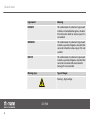
1
PAR64 PRO 36x3W
Par56 Pro 24x3W
Mini Stage Par 7x3W
Stage PAR 18 Tri-Color LED3W
LED PAR
user manual
Musikhaus Thomann e.K.
Treppendorf 30
96138 Burgebrach
Germany
Telephone: +49 (0) 9546 9223-0
E-mail: [email protected]
Internet: www.thomann.de
24.01.2013
Table of contents
Table of contents
1
General notes............................................................................................................................................... 5
2
Safety instructions..................................................................................................................................... 8
3
Features....................................................................................................................................................... 12
4
Installation.................................................................................................................................................. 13
5
Starting up.................................................................................................................................................. 16
6
Connections and operating elements........................................................................................... 19
7
Operation....................................................................................................................................................
7.1 Introduction.......................................................................................................................................
7.2 Operating modes.............................................................................................................................
7.3 Starting up the device....................................................................................................................
7.4 Function selection...........................................................................................................................
7.5 Auto-change mode.........................................................................................................................
7.6 Auto fade mode................................................................................................................................
7.7 Manual mode.....................................................................................................................................
7.8 5-channel DMX slave mode..........................................................................................................
22
22
23
25
26
27
31
35
39
PAR64 PRO 36x3WPar56 Pro 24x3W Mini Stage Par 7x3W
Stage PAR 18 Tri-Color LED3W
3
Table of contents
7.9 5-channel DMX master mode...................................................................................................... 47
7.10 3-channel DMX slave mode....................................................................................................... 66
7.11 3-channel DMX master mode................................................................................................... 72
8
Technical specifications....................................................................................................................... 83
9
Troubleshooting...................................................................................................................................... 86
10
Cleaning....................................................................................................................................................... 88
11
Protecting the environment.............................................................................................................. 89
LED PAR
4
General notes
1
General notes
This user manual contains important information on safe operation of the device. Read and
follow all safety notes and all instructions. Save this manual for future reference. Make sure
that it is available to all persons using this device. If you sell the device, include the manual for
the next owner.
Our products are subject to a process of continuous development. We therefore reserve the
right to make changes without notice.
Symbols and signal words
This section provides an overview of the symbols and signal words used in this user manual.
PAR64 PRO 36x3WPar56 Pro 24x3W Mini Stage Par 7x3W
Stage PAR 18 Tri-Color LED3W
5
General notes
Signal word
Meaning
DANGER!
This combination of symbol and signal word
indicates an immediate dangerous situation
that will result in death or serious injury if it is
not avoided.
WARNING!
This combination of symbol and signal word
indicates a possible dangerous situation that
can result in death or serious injury if it is not
avoided.
NOTICE!
This combination of symbol and signal word
indicates a possible dangerous situation that
can result in material and environmental
damage if it is not avoided.
Warning signs
Type of danger
Warning – high-voltage.
LED PAR
6
General notes
Warning signs
Type of danger
Warning – suspended load.
Warning – danger zone.
PAR64 PRO 36x3WPar56 Pro 24x3W Mini Stage Par 7x3W
Stage PAR 18 Tri-Color LED3W
7
Safety instructions
2
Safety instructions
Intended use
This device is intended to be used as an electronic illumination effect using LED technics. Use
the device only as described in this user manual. Any other use or use under other operating
conditions is considered to be improper and may result in personal injury or property damage.
No liability will be assumed for damages resulting from improper use.
This device may be used only by persons with sufficient physical, sensorial, and intellectual
abilities and having corresponding knowledge and experience. Other persons may use this
device only if they are supervised or instructed by a person who is responsible for their safety.
Safety
DANGER!
Danger for children
Ensure that plastic bags, packaging, etc. are disposed of properly and are not
within reach of babies and young children. Choking hazard!
Ensure that children do not detach any small parts (e.g. knobs or the like) from
the unit. They could swallow the pieces and choke!
Never let children unattended use electrical devices.
LED PAR
8
Safety instructions
DANGER!
Electric shock caused by short-circuit
Do not modify the mains cable or the plug. Failure to do so could result in electric
shock/death or fire. If in doubt, seek advice from a registered electrician.
DANGER!
Electric shock caused by high voltages inside
Within the device there are areas where high voltages may be present. Never
remove any covers.
There are no user-serviceable parts inside.
WARNING!
Eye damage caused by high light intensity
Never look directly into the light source.
PAR64 PRO 36x3WPar56 Pro 24x3W Mini Stage Par 7x3W
Stage PAR 18 Tri-Color LED3W
9
Safety instructions
WARNING!
Risk of epileptic shock
Strobe lighting can trigger seizures in photosensitive epilepsy. Sensitive persons
should avoid looking at strobe lights.
NOTICE!
Risk of fire
Do not cover the device nor any ventilation slots. Do not place the device near
any direct heat source. Keep the device away from naked flames.
NOTICE!
Operating conditions
This device has been designed for indoor use only. To prevent damage, never
expose the device to any liquid or moisture. Avoid direct sunlight, heavy dirt, and
strong vibrations.
LED PAR
10
Safety instructions
NOTICE!
Power supply
Before connecting the device, ensure that the input voltage (AC outlet) matches
the voltage rating of the device and that the AC outlet is protected by a residual
current circuit breaker. Failure to do so could result in damage to the device and
possibly injure the user.
Unplug the device before electrical storms occur and when it is unused for long
periods of time to reduce the risk of electric shock or fire.
PAR64 PRO 36x3WPar56 Pro 24x3W Mini Stage Par 7x3W
Stage PAR 18 Tri-Color LED3W
11
Features
3
Features
The LED PAR is particularly suitable for professional lighting applications, e.g. at events, on
rock stages, in theatres and musicals or TV productions. It is characterized by a low power con‐
sumption and long life span.
Special features of this device:
n
n
n
n
n
n
Tricolour LEDs (RGB)
Control via DMX or DIP switches on the unit
Preprogrammed automatic shows
Sound control
Master / slave mode
Robust metal housing
LED PAR
12
Installation
4
Installation
Unpack and check carefully there is no transportation damage before using the unit. Keep the
equipment packaging. To fully protect the device against vibration, dust and moisture during
transportation or storage use the original packaging or your own packaging material suitable
for transport or storage, respectively.
You can install the device on the wall, ceiling or floor. A mounting bracket and the necessary
screws are included in the package.
WARNING!
Risk of injury caused by falling objects
Make sure that the installation complies with the standards and rules that apply
in your country. Always secure the device with a secondary safety attachment,
such as a safety cable or a safety chain.
PAR64 PRO 36x3WPar56 Pro 24x3W Mini Stage Par 7x3W
Stage PAR 18 Tri-Color LED3W
13
Installation
NOTICE!
Risk of overheating
Always ensure sufficient ventilation.
The ambient temperature must always be below 40 °C (104 °F).
NOTICE!
Use of stands
When mounting the device onto a stand, ensure that the stand is in a safe and
stable position and that the weight of the device does not exceed the maximum
permissible load capacity of the stand.
LED PAR
14
Installation
NOTICE!
Possible data transmission errors
For error-free operation make use of dedicated DMX cables and do not use ordi‐
nary microphone cables.
Never connect the DMX output to audio devices such as mixers or amplifiers.
DMX connections
The unit offers a 3-pin XLR socket for DMX output and a 3-pin XLR plug for DMX input. Please
refer to the drawing and table below for pin assignment.
1
Ground, shielding
2
DMX data (–)
3
DMX data (+)
PAR64 PRO 36x3WPar56 Pro 24x3W Mini Stage Par 7x3W
Stage PAR 18 Tri-Color LED3W
15
Starting up
5
Starting up
Establish all connections as long as the unit is switched off. Use the shortest possible highquality cables for all connections.
LED PAR
16
Starting up
Connections in DMX mode
Connect the DMX input of the device to the DMX output of a DMX controller or another DMX
device. Connect the output of the first DMX device to the input of the second one, and so on
to form a daisy chain. Always ensure that the output of the last DMX device in the daisy chain
is terminated with a resistor (110 Ω, ¼ W).
PAR64 PRO 36x3WPar56 Pro 24x3W Mini Stage Par 7x3W
Stage PAR 18 Tri-Color LED3W
17
Starting up
Connections in master/slave
mode
When you configure a group of devices in master/slave mode, the first unit will control the
other units for an automatic, sound-activated, synchronized show. This function is ideal when
you want to start a show immediately. Connect the DMX output of the master device to the
DMX input of the first slave device. Then connect the DMX output of the first slave device to
the DMX input of the second slave device and so on.
LED PAR
18
Connections and operating elements
6
Connections and operating elements
Rear panel
PAR64 PRO 36x3WPar56 Pro 24x3W Mini Stage Par 7x3W
Stage PAR 18 Tri-Color LED3W
19
Connections and operating elements
1 Mains cable.
2 Bracket for hanging or setting up.
3 Locking screw for the bracket.
4 DMX IN
DMX input.
5 DMX OUT
DMX output.
6 SPEED
For manual speed adjustment.
7 MUSIC
Sensitivity control for the built-in microphone.
LED PAR
20
Connections and operating elements
8 FUNCTION
This 4-way DIP switch sets the operating mode of the LED PAR.
9 PATTERN
The function of this 10-way DIP switch depends on the current operating mode, e.g. in follow mode, the follow pat‐
tern can be selected here.
PAR64 PRO 36x3WPar56 Pro 24x3W Mini Stage Par 7x3W
Stage PAR 18 Tri-Color LED3W
21
Operation
7
Operation
7.1 Introduction
The main characteristic of the LED PAR spotlights is the usability as 5-channel DMX controller.
In this mode, the DMX in and outputs of 4 LED PAR lights must be connected via XLR cable.
The first LED PAR must be switched to DMX ‘Master’ mode. Then this light sends signals to the
other connected devices, the ‘slaves’. Various display patterns are available: e.g. all connected
devices can show the same pattern, or each device shows a different one, or follow pro‐
grammes or fade in / outs or blendings. The individual steps within the patterns can be con‐
trolled by the rhythm of the music or using a controller. The sensitivity of the sound-control is
adjustable. The colour patterns offer a 100% colour mode, a 100% / 50% colour mode as well
as a 100% / 75% / 50% / 25% colour mode. The colours are then selected randomly.
It also supports a 3-channel DMX slave mode for easy integration into a DMX system.
All 512 channels can be used.
The device also supports the stand-alone modes ‘Auto change mode’, ‘Auto fade mode’ and
‘Manual mode’.
LED PAR
22
Operation
7.2 Operating modes
7.2.1 DMX modes
5-channel DMX master mode
In this mode, the LED PAR is used as a 5-channel DMX master. The 5-channel DMX master
mode ensures compatibility to the first version of the LED PARs. The 5-channel DMX master
mode utilises built-in features of the LED PARs, which are controlled via the DMX signal.
3 different patterns are available: e.g. all connected LED PARs can show the same pattern, or
each device shows a different one, or follow programmes or fade in / outs or blendings. The
individual steps within the patterns can be controlled by the rhythm of the music or using a
controller. The sensitivity of the sound-control is adjustable. The colour patterns offer a 100%
colour mode, a 100% / 50% colour mode as well as a 100% / 75% / 50% / 25% colour mode.
The colours are then selected randomly.
3-channel DMX master mode
In this mode, the LED PAR is used as a 3-channel DMX master. The 3-channel DMX master
mode occupies less DMX channels, e.g. when connecting DMX power packs or other equip‐
ment that receives DMX signals.
PAR64 PRO 36x3WPar56 Pro 24x3W Mini Stage Par 7x3W
Stage PAR 18 Tri-Color LED3W
23
Operation
3 different patterns are available: e.g. all connected LED PARs can show the same pattern, or
each device shows a different one, or follow programmes or fade in / outs or blendings. The
individual steps within the patterns can be controlled by the rhythm of the music or using a
controller. The sensitivity of the sound-control is adjustable. The colour patterns offer a 100%
colour mode, a 100% / 50% colour mode as well as a 100% / 75% / 50% / 25% colour mode.
The colours are then selected randomly.
5-channel DMX slave mode
In this mode, the LED PAR is used as DMX slave. The 5-channel DMX slave mode utilises built-in
features of the LED PARs, which are controlled via the DMX signal. An external DMX controller
controls the LED PAR.
3-channel DMX slave mode
The 3-channel slave mode is for use with a standard DMX controller. The LED PAR can be con‐
trolled via all 512 channels. Each colour is controlled via one DMX channel.
7.2.2 Stand-alone modes
Auto-fade mode
The Auto-fade mode is available with 3 different patterns for fade in / outs or blendings.
The times for fade in / outs or blendings can be determined exactly by 9 time settings.
LED PAR
24
Operation
The Auto-fade mode supports several colour change patterns: The colour patterns offer a
100% colour mode, a 100% / 50% colour mode as well as a 100% / 75% / 50% / 25% colour
mode. The colours are then selected randomly.
Auto-change mode
The Auto-change mode supports various colour change patterns. The colour patterns offer a
100% colour mode, a 100% / 50% colour mode as well as a 100% / 75% / 50% / 25% colour
mode. The colours are then selected randomly.
The change speed can be set by the rhythm of the music or with a controller.
Manual mode
In manual mode, each colour can be turned on in steps of about 14%.
7.3 Starting up the device
Connect the unit to the power grid to start the operation. After a few seconds the unit is ready
for use.
PAR64 PRO 36x3WPar56 Pro 24x3W Mini Stage Par 7x3W
Stage PAR 18 Tri-Color LED3W
25
Operation
7.4 Function selection
You can set the operating mode of the LED PARS according to the following table using the 4way DIP switches FUNCTION on the rear panel:
SW4
SW3
SW2
SW1
Mode
X
0
0
0
Auto-change mode
X
0
0
1
Auto-fade mode
X
0
1
0
Manual mode
X
0
1
1
5-channel DMX slave mode
X
1
0
0
5-channel DMX master mode
X
1
0
1
3-channel DMX slave mode
X
1
1
0
3-channel DMX master mode
X
1
1
1
No new mode (3-channel DMX master mode is used)
LED PAR
26
Operation
SW4
SW3
SW2
SW1
Mode
0
X
X
X
Speed controlled by controller, if supported by the selected
operating mode
1
X
X
X
Speed controlled by music, if supported by the selected oper‐
ating mode
0 = DIP switch is in ‘OFF’ position. 1 = DIP switch is in ‘ON’ position. X = see more / above infor‐
mation.
7.5 Auto-change mode
The LED PAR shows different colours depending on the speed selection. In this mode, the LED
PAR is used as a stand-alone device, the DMX in and outputs remain unused.
PAR64 PRO 36x3WPar56 Pro 24x3W Mini Stage Par 7x3W
Stage PAR 18 Tri-Color LED3W
27
Operation
Mode selection
To enable the auto-change mode, set the 4-way DIP switch on the rear side of the LED PAR
according to the following table:
SW4
SW3
SW2
SW1
X
0
0
0
Mode
Auto-change mode
0 = DIP switch is in ‘OFF’ position. 1 = DIP switch is in ‘ON’ position. X = see more / above infor‐
mation.
LED PAR
28
Operation
Setting the speed
Using SW4 you can set how the speed is controlled. Then orientate yourself on the following
table:
SW4
SW3
SW2
SW1
Mode
0
0
0
0
Speed controlled by controller, if supported by the selected
operating mode
1
0
0
0
Speed controlled by music, if supported by the selected oper‐
ating mode
0 = DIP switch is in ‘OFF’ position. 1 = DIP switch is in ‘ON’ position.
PAR64 PRO 36x3WPar56 Pro 24x3W Mini Stage Par 7x3W
Stage PAR 18 Tri-Color LED3W
29
Operation
Setting the colour pattern
You can set the colour patterns according to the following table using the 10-way DIP switch
on the rear panel of the LED PAR:
SW10
SW9
SW8
SW7
SW6
SW5
SW4
SW3
SW2
SW1
Selecting the colour pattern
0
0
0
0
0
0
0
0
0
0
Compatibility mode - old pattern
style
0
0
0
0
0
0
0
0
0
1
100% colour change
0
0
0
0
0
0
0
0
1
0
100%, 50% colour change
0
0
0
0
0
0
0
0
1
1
100%, 75%, 50%, 25% colour change
0 = DIP switch is in ‘OFF’ position. 1 = DIP switch is in ‘ON’ position.
If a different colour pattern is set, always pattern ‘0000000011’ is used.
LED PAR
30
Operation
7.6 Auto fade mode
The LED PAR shows colour fadings depending on the speed selection. In this mode, the LED
PAR is used as a stand-alone device, the DMX in / outputs remain unused.
Setting the mode
To activate the automatic fade mode, set the 4-way DIP switch on the back of the LED PAR
according to the following table:
SW4
SW3
SW2
SW1
X
0
0
1
Mode
Auto fade mode
0 = DIP switch is in ‘OFF’ position. 1 = DIP switch is in ‘ON’ position. X = in this mode, speed
control by controller or music is not supported.
PAR64 PRO 36x3WPar56 Pro 24x3W Mini Stage Par 7x3W
Stage PAR 18 Tri-Color LED3W
31
Operation
Setting the fade speed
You can adjust the speed of the fading using the 10-way DIP switch on the back of the LED PAR
according the following table:
SW10
SW9
SW8
SW7
SW6
SW5
SW4
SW3
SW2
SW1
0
0
0
X
X
X
0
0
0
0
630 s (10:30 min)
0
0
0
X
X
X
0
0
0
1
2.5 s
0
0
0
X
X
X
0
0
1
0
5s
0
0
0
X
X
X
0
0
1
1
10 s
0
0
0
X
X
X
0
1
0
0
20 s
0
0
0
X
X
X
0
1
0
1
40 s
0
0
0
X
X
X
0
1
1
0
80 s
0
0
0
X
X
X
0
1
1
1
160 s
0
0
0
X
X
X
1
0
0
0
320 s
LED PAR
32
Selection of fading speed
Operation
0 = DIP switch is in ‘OFF’ position. 1 = DIP switch is in ‘ON’ position. X = see below for more
information.
If a different timing pattern is set, always pattern ‘000xxx1000’ is used.
in this mode, speed control by controller or music is not supported.
PAR64 PRO 36x3WPar56 Pro 24x3W Mini Stage Par 7x3W
Stage PAR 18 Tri-Color LED3W
33
Operation
Setting the colour patterns
You can adjust the colour patterns using the 10-way DIP switch on the back of the LED PAR
according the following table:
SW
10
SW
9
SW
8
SW
7
SW
6
SW
5
SW
4
SW
3
SW
2
SW
1
Selection of colour patterns
0
0
0
0
0
0
X
X
X
X
Compatibility mode - old pattern style
0
0
0
0
0
1
X
X
X
X
100% colour change, fade in and out
0
0
0
0
1
0
X
X
X
X
100%, 50% colour change, fade in and out
0
0
0
0
1
1
X
X
X
X
100%, 75%, 50%, 25% colour change, fade in and out
0
0
0
1
0
0
X
X
X
X
100% colour change, fade in
0
0
0
1
0
1
X
X
X
X
100%, 50% colour change, fade in
0
0
0
1
1
0
X
X
X
X
100%, 75%, 50%, 25% colour change, fade in
0 = DIP switch is in ‘OFF’ position. 1 = DIP switch is in ‘ON’ position. X = see above for more
information.
If a different colour pattern is set, always pattern ‘000110xxxx’ is used.
LED PAR
34
Operation
7.7 Manual mode
The LED PAR shows different fixed colours. In this mode the LED PAR is used as a stand-alone
device, the DMX in / outputs remain unused.
Setting the mode
To activate the manual mode, set the 4-way DIP switch on the back of the LED PAR according
to the following table:
SW4
SW3
SW2
SW1
X
0
1
0
Mode
Manual mode
0 = DIP switch is in ‘OFF’ position. 1 = DIP switch is in ‘ON’ position. X = in this mode, speed
control by controller or music is not supported.
PAR64 PRO 36x3WPar56 Pro 24x3W Mini Stage Par 7x3W
Stage PAR 18 Tri-Color LED3W
35
Operation
Red colour
Adjust the colour pattern
The red colour can be set using the 10-way DIP switch on the back of the LED PAR according to
the following table:
SW10
SW9
SW8
SW7
SW6
SW5
SW4
SW3
SW2
SW1
Brightness of the colour red
0
X
X
X
X
X
X
0
0
0
0%
0
X
X
X
X
X
X
0
0
1
14%
0
X
X
X
X
X
X
0
1
0
28%
0
X
X
X
X
X
X
0
1
1
42%
0
X
X
X
X
X
X
1
0
0
57%
0
X
X
X
X
X
X
1
0
1
71%
0
X
X
X
X
X
X
1
1
0
85%
0
X
X
X
X
X
X
1
1
1
100%
0 = DIP switch is in ‘OFF’ position. 1 = DIP switch is in ‘ON’ position. X = see below for more
information.
LED PAR
36
Operation
Green colour
The green colour can be set using the 10-way DIP switch on the back of the LED PAR according
to the following table:
SW10
SW9
SW8
SW7
SW6
SW5
SW4
SW3
SW2
SW1
Brightness of the colour green
0
X
X
X
0
0
0
X
X
X
0%
0
X
X
X
0
0
1
X
X
X
14%
0
X
X
X
0
1
0
X
X
X
28%
0
X
X
X
0
1
1
X
X
X
42%
0
X
X
X
1
0
0
X
X
X
57%
0
X
X
X
1
0
1
X
X
X
71%
0
X
X
X
1
1
0
X
X
X
85%
0
X
X
X
1
1
1
X
X
X
100%
0 = DIP switch is in ‘OFF’ position. 1 = DIP switch is in ‘ON’ position. X = see more information
above and below.
PAR64 PRO 36x3WPar56 Pro 24x3W Mini Stage Par 7x3W
Stage PAR 18 Tri-Color LED3W
37
Operation
Blue colour
The blue colour can be set using the 10-way DIP switch on the back of the LED PAR according
to the following table:
SW10
SW9
SW8
SW7
SW6
SW5
SW4
SW3
SW2
SW1
Brightness of the colour blue
0
0
0
0
X
X
X
X
X
X
0%
0
0
0
1
X
X
X
X
X
X
14%
0
0
1
0
X
X
X
X
X
X
28%
0
0
1
1
X
X
X
X
X
X
42%
0
1
0
0
X
X
X
X
X
X
57%
0
1
0
1
X
X
X
X
X
X
71%
0
1
1
0
X
X
X
X
X
X
85%
0
1
1
1
X
X
X
X
X
X
100%
0 = DIP switch is in ‘OFF’ position. 1 = DIP switch is in ‘ON’ position. X = see more information
above.
LED PAR
38
Operation
7.8 5-channel DMX slave mode
Setting the mode
To activate the 5-channel DMX slave mode, set the 4-way DIP switch on the back of the LED
PAR according to the following table:
SW4
SW3
SW2
SW1
X
0
1
1
Mode
5-channel DMX slave mode
0 = DIP switch is in ‘OFF’ position. 1 = DIP switch is in ‘ON’ position. X = see below for more
information.
PAR64 PRO 36x3WPar56 Pro 24x3W Mini Stage Par 7x3W
Stage PAR 18 Tri-Color LED3W
39
Operation
Setting the speed
Use SW4 to set how the speed is controlled. Orientate yourself on the following table:
SW4
SW3
SW2
SW1
Mode
0
0
1
1
Speed controlled by controller, if supported by the selected
operating mode
1
0
1
1
Speed control by music, if supported by the selected oper‐
ating mode
0 = DIP switch is in ‘OFF’ position. 1 = DIP switch is in ‘ON’ position.
LED PAR
40
Operation
DMX allocation
This table shows the DMX values that can be sent from an external DMX controller to the LED
PAR:
Channel 1 value
Function
0…63
RGB control, CH2 = red, CH3 = green, CH4 = blue
64…127
7-fold colour fade, CH5 = speed control
128…191
7-fold colour change, CH5 = speed control
192…255
3-fold colour change, CH5 = speed control
Channel 2 value
Function
0…255
Red colour: 0%…100%
Channel 3 value
Function
0…255
Green colour: 0%…100%
PAR64 PRO 36x3WPar56 Pro 24x3W Mini Stage Par 7x3W
Stage PAR 18 Tri-Color LED3W
41
Operation
Channel 4 value
Function
0…255
Blue colour: 0%…100%
Channel 5 value
Function
0…10
no function – no speed
11…100
Speed low to high
101…150
no function – no speed
151…255
Speed control via device, music or controller
LED PAR
42
Operation
Setting DMX receive channel
The value of the DIP switches 1 to 9 is binary coded. To set up a desired DMX receive channel,
set the DIP switches so that the sum of the resulting channel numbers results in the desired
number. Orientate yourself on the following table:
SW10
SW9
SW8
SW7
SW6
SW5
SW4
SW3
SW2
SW1
First DMX receive channel
0
0
0
0
0
0
0
0
0
1
1
0
0
0
0
0
0
0
0
1
0
2
0
0
0
0
0
0
0
1
0
0
4
0
0
0
0
0
0
1
0
0
0
8
0
0
0
0
0
1
0
0
0
0
16
0
0
0
0
1
0
0
0
0
0
32
0
0
0
1
0
0
0
0
0
0
64
0
0
1
0
0
0
0
0
0
0
128
0
1
0
0
0
0
0
0
0
0
256
PAR64 PRO 36x3WPar56 Pro 24x3W Mini Stage Par 7x3W
Stage PAR 18 Tri-Color LED3W
43
Operation
0 = DIP switch is in ‘OFF’ position. 1 = DIP switch is in ‘ON’ position.
If only DIP switch 1 is set to ‘ON’, the first DMX receive channel is ‘1’. The highest possible first
receiving channel is ‘508’. If you have configured a higher number than 508, channel 508
remains enabled.
LED PAR
44
Operation
Examples
Example A, the first DMX receive channel is channel 1
SW10
SW9
SW8
SW7
SW6
SW5
SW4
SW3
SW2
SW1
0
0
0
0
0
0
0
0
0
1
First DMX receive channel
1
The unit starts receiving on DMX channel 1. This occupies channels 1, 2, 3, 4 and 5.
Example B, the first DMX receive channel is channel 22
SW10
SW9
SW8
SW7
SW6
SW5
SW4
SW3
SW2
SW1
0
0
0
0
0
1
0
1
1
0
First DMX receive channel
22
The unit starts receiving on DMX channel 22. This occupies channels 22, 23, 24, 25 and 26.
Example C, the first DMX receive channel is channel 272
PAR64 PRO 36x3WPar56 Pro 24x3W Mini Stage Par 7x3W
Stage PAR 18 Tri-Color LED3W
45
Operation
SW10
SW9
SW8
SW7
SW6
SW5
SW4
SW3
SW2
SW1
0
1
0
0
0
1
0
0
0
0
First DMX receive channel
272
The unit starts receiving on DMX channel 272. This occupies channels 272, 273, 274, 275 and
276.
Example D, the first DMX receive channel is channel 508
SW10
SW9
SW8
SW7
SW6
SW5
SW4
SW3
SW2
SW1
0
1
1
1
1
1
1
1
0
0
First DMX receive channel
508
The unit starts receiving on DMX channel 508. This occupies channels 508, 509, 510, 511 and
512.
LED PAR
46
Operation
7.9 5-channel DMX master mode
In this mode, the device operates as a DMX controller in 5-channel mode. The 5-channel mode
is used to control both the current and the older revision of the LED PARs. The connected slave
devices must be set as 5-channel slaves (Ä Chapter 7.8 ‘5-channel DMX slave mode’ on page 39).
Setting the mode
To activate the 5-channel DMX master mode, set the 4-way DIP switch on the back of the LED
PAR according to the following table:
SW4
SW3
SW2
SW1
X
1
0
0
Mode
5-channel DMX master mode
0 = DIP switch is in ‘OFF’ position. 1 = DIP switch is in ‘ON’ position. X = see below for more
information.
PAR64 PRO 36x3WPar56 Pro 24x3W Mini Stage Par 7x3W
Stage PAR 18 Tri-Color LED3W
47
Operation
Setting the speed
Use SW4 to set how the speed is controlled. Orientate yourself on the following table:
SW4
SW3
SW2
SW1
Mode
0
1
0
0
Speed controlled by controller, if supported by the selected
operating mode
1
1
0
0
Speed control by music, if supported by the selected oper‐
ating mode
0 = DIP switch is in ‘OFF’ position. 1 = DIP switch is in ‘ON’ position.
LED PAR
48
Operation
DMX use with 5-channel control
In master mode, the LED PAR sends DMX data according to the following table. The connected
slave devices must be set as 5-channel DMX-slaves (Ä Chapter 7.8 ‘5-channel DMX slave mode’
on page 39).
Spot light
Chann
el
1
1
DMX CH = 0, RGB control
2
DMX CH = RED
3
DMX CH = GREEN
4
DMX CH = BLUE
5
DMX CH = 0, no function, no speed
6
DMX CH = 0, RGB control
7
DMX CH = RED
8
DMX CH = GREEN
9
DMX CH = BLUE
2
PAR64 PRO 36x3WPar56 Pro 24x3W Mini Stage Par 7x3W
Stage PAR 18 Tri-Color LED3W
49
Operation
Spot light
3
4
Chann
el
10
DMX CH = 0, no function, no speed
11
DMX CH = 0, RGB control
12
DMX CH = RED
13
DMX CH = GREEN
14
DMX CH = BLUE
15
DMX CH = 0, no function, no speed
16
DMX CH = 0, RGB control
17
DMX CH = RED
18
DMX CH = GREEN
19
DMX CH = BLUE
20
DMX CH = 0, no function, no speed
LED PAR
50
Operation
Setting the colour pattern
You can set the colour pattern using the 10-way DIP switch on the back of the LED PAR
according to the following table:
Colour pattern
All LED PARs are turned on and change colour.
SW
10
SW
9
SW
8
SW
7
SW
6
SW
5
SW
4
SW
3
SW
2
SW
1
Colour pattern
0
0
0
0
0
0
0
0
0
0
4 spot lights, pattern 1, all on, all carry out the same
0
0
0
0
0
0
0
0
0
1
4 spot lights, pattern 2, all on, all carry out the same
0
0
0
0
0
0
0
0
1
0
4 spot lights, pattern 3, all on, all carry out the same
0
0
0
0
0
0
0
0
1
1
4 spot lights, pattern 1, all on, each device has its own pattern
0
0
0
0
0
0
0
1
0
0
4 spot lights, pattern 2, all on, each device has its own pattern
0
0
0
0
0
0
0
1
0
1
4 spot lights, pattern 3, all on, each device has its own pattern
0 = DIP switch is in ‘OFF’ position. 1 = DIP switch is in ‘ON’ position.
PAR64 PRO 36x3WPar56 Pro 24x3W Mini Stage Par 7x3W
Stage PAR 18 Tri-Color LED3W
51
Operation
Fading In / Out colour pattern
The colour is faded in and out.
SW
10
SW
9
SW
8
SW
7
SW
6
SW
5
SW
4
SW
3
SW
2
SW
1
Colour pattern
0
0
0
0
0
0
0
1
1
0
4 spot lights, pattern 1, all on, all carry out the same, incl. fade
in / out
0
0
0
0
0
0
0
1
1
1
4 spot lights, pattern 2, all on, all carry out the same, incl. fade
in / out
0
0
0
0
0
0
1
0
0
0
4 spot lights, pattern 3, all on, all carry out the same, incl. fade
in / out
0
0
0
0
0
0
1
0
0
1
4 spot lights, pattern 1, all on, each device has its own pattern,
incl. fade in / out
LED PAR
52
Operation
SW
10
SW
9
SW
8
SW
7
SW
6
SW
5
SW
4
SW
3
SW
2
SW
1
Colour pattern
0
0
0
0
0
0
1
0
1
0
4 spot lights, pattern 2, all on, each device has its own pattern,
incl. fade in / out
0
0
0
0
0
0
1
0
1
1
4 spot lights, pattern 3, all on, each device has its own pattern,
incl. fade in / out
0 = DIP switch is in ‘OFF’ position. 1 = DIP switch is in ‘ON’ position.
Colour pattern ‘Fading Over’ (colour cross-fade)
Colour is cross-faded.
SW
10
SW
9
SW
8
SW
7
SW
6
SW
5
SW
4
SW
3
SW
2
SW
1
Colour pattern
0
0
0
0
0
0
1
1
0
0
4 spot lights, pattern 1, all on, all carry out the same
0
0
0
0
0
0
1
1
0
1
4 spot lights, pattern 2, all on, all carry out the same
0
0
0
0
0
0
1
1
1
0
4 spot lights, pattern 3, all on, all carry out the same
PAR64 PRO 36x3WPar56 Pro 24x3W Mini Stage Par 7x3W
Stage PAR 18 Tri-Color LED3W
53
Operation
SW
10
SW
9
SW
8
SW
7
SW
6
SW
5
SW
4
SW
3
SW
2
SW
1
Colour pattern
0
0
0
0
0
0
1
1
1
1
4 spot lights, pattern 1, all on, each device has its own pattern,
incl. fading over
0
0
0
0
0
1
0
0
0
0
4 spot lights, pattern 2, all on, each device has its own pattern,
incl. fading over
0
0
0
0
0
1
0
0
0
1
4 spot lights, pattern 3, all on, each device has its own pattern,
incl. fading over
0 = DIP switch is in ‘OFF’ position. 1 = DIP switch is in ‘ON’ position.
Follow colour pattern (one of 4 LED PARs is on)
LED PAR
54
Operation
SW
10
SW
9
SW
8
SW
7
SW
6
SW
5
SW
4
SW
3
SW
2
SW
1
Colour pattern
0
0
0
0
0
1
0
0
1
0
Follow pattern 1, right to left, same colour for each step
0
0
0
0
0
1
0
0
1
1
Follow pattern 1, right to left – left to right, same colour for each
step
0
0
0
0
0
1
0
1
0
0
Follow pattern 2, right to left, same colour for each step
0
0
0
0
0
1
0
1
0
1
Follow pattern 2, right to left – left to right, same colour for each
step
0
0
0
0
0
1
0
1
1
0
Follow pattern 3, right to left, same colour for each step
0
0
0
0
0
1
0
1
1
1
Follow pattern 3, right to left – left to right, same colour for each
step
0
0
0
0
0
1
1
0
0
0
Follow pattern 1, right to left, new colour for each step
PAR64 PRO 36x3WPar56 Pro 24x3W Mini Stage Par 7x3W
Stage PAR 18 Tri-Color LED3W
55
Operation
SW
10
SW
9
SW
8
SW
7
SW
6
SW
5
SW
4
SW
3
SW
2
SW
1
Colour pattern
0
0
0
0
0
1
1
0
0
1
Follow pattern 1, right to left – left to right, new colour for each
step
0
0
0
0
0
1
1
0
1
0
Follow pattern 2, right to left, new colour for each step
0
0
0
0
0
1
1
0
1
1
Follow pattern 2, right to left – left to right, new colour for each
step
0
0
0
0
0
1
1
1
0
0
Follow pattern 3, right to left, new colour for each step
0
0
0
0
0
1
1
1
0
1
Follow pattern 3, right to left - left to right, new colour for each
step
0 = DIP switch is in ‘OFF’ position. 1 = DIP switch is in ‘ON’ position.
Follow colour pattern (two of four LED PARs are on)
LED PAR
56
Operation
SW
10
SW
9
SW
8
SW
7
SW
6
SW
5
SW
4
SW
3
SW
2
SW
1
Colour pattern
0
0
0
0
0
1
1
1
1
0
Follow pattern 1, right to left, new colour for each step
0
0
0
0
0
1
1
1
1
1
Follow pattern 1, right to left – left to right, new colour for each
step
0
0
0
0
1
0
0
0
0
0
Follow pattern 2, right to left, new colour for each step
0
0
0
0
1
0
0
0
0
1
Follow pattern 2, right to left – left to right, new colour for each
step
0
0
0
0
1
0
0
0
1
0
Follow pattern 3, right to left, new colour for each step
0
0
0
0
1
0
0
0
1
1
Follow pattern 3, right to left – left to right, new colour for each
step
0
0
0
0
1
0
0
1
0
0
Follow pattern 1, right to left, each device has its own pattern,
new colour for each step
PAR64 PRO 36x3WPar56 Pro 24x3W Mini Stage Par 7x3W
Stage PAR 18 Tri-Color LED3W
57
Operation
SW
10
SW
9
SW
8
SW
7
SW
6
SW
5
SW
4
SW
3
SW
2
SW
1
Colour pattern
0
0
0
0
1
0
0
1
0
1
Follow pattern 1, right to left – left to right, each device has its
own pattern, new colour for each step
0
0
0
0
1
0
0
1
1
0
Follow pattern 2, right to left, each device has its own pattern,
new colour for each step
0
0
0
0
1
0
0
1
1
1
Follow pattern 2, right to left – left to right, each device has its
own pattern, new colour for each step
0
0
0
0
1
0
1
0
0
0
Follow pattern 3, right to left, each device has its own pattern,
new colour for each step
0
0
0
0
1
0
1
0
0
1
Follow pattern 3, right to left – left to right, each device has its
own pattern, new colour for each step
0 = DIP switch is in ‘OFF’ position. 1 = DIP switch is in ‘ON’ position.
LED PAR
58
Operation
Example A
Examples
This example shows how to set up 4 LED PARs that are controlled in 5-channel DMX-Master
mode.
Connection: MASTER: device 1, SLAVE1: device 2, SLAVE2: device 3, SLAVE3: device 4.
MASTER setup, device 1, must be configured as follows:
SW
10
SW
9
SW
8
SW
7
SW
6
SW
5
SW
4
SW
3
SW
2
SW
1
0
0
0
0
0
1
0
0
1
0
SW4
SW3
SW2
SW1
0
1
0
0
Colour pattern
Follow pattern 1, right to left, same colour for each step
Mode
5-channel DMX master mode, speed control via controller
This occupies channels 1, 2, 3, 4 and 5.
SLAVE 1 setup, device 2, DMX start channel 6:
PAR64 PRO 36x3WPar56 Pro 24x3W Mini Stage Par 7x3W
Stage PAR 18 Tri-Color LED3W
59
Operation
10-way DIP switch PATTERN
4-way DIP switch FUNCTION
SW10
SW9
SW8
SW7
SW6
SW5
SW4
SW3
SW2
SW1
SW4
SW3
SW2
SW1
0
0
0
0
0
0
0
1
1
0
0
0
1
1
The unit starts to receive with DMX channel 6. This occupies channels 6, 7, 8, 9 and 10.
SLAVE 2 setup, device 3, DMX start channel 11:
10-way DIP switch PATTERN
4-way DIP switch FUNCTION
SW10
SW9
SW8
SW7
SW6
SW5
SW4
SW3
SW2
SW1
SW4
SW3
SW2
SW1
0
0
0
0
0
0
1
0
1
0
0
0
1
1
The unit starts to receive with DMX channel 11. This occupies channels 11, 12, 13, 14 and 15.
SLAVE 3 setup, device 4, DMX start channel 16:
LED PAR
60
Operation
10-way DIP switch PATTERN
4-way DIP switch FUNCTION
SW10
SW9
SW8
SW7
SW6
SW5
SW4
SW3
SW2
SW1
SW4
SW3
SW2
SW1
0
0
0
0
0
1
0
0
0
0
0
0
1
1
The unit starts to receive with DMX channel 16. This occupies channels 16, 17, 18, 19 and 20.
Example B
This example shows how to set up 8 LED PARs that are controlled in 5-channel master mode.
The patterns are being sent yet for 4 channels.
Connection: MASTER: device 1, SLAVE1: device 2, SLAVE2: device 3, SLAVE3: device 4, SLAVE4:
device 5, SLAVE5: device 6, SLAVE6: device 7, SLAVE7: device 8.
MASTER setup, device 1, must be set up as follows:
SW
10
SW
9
SW
8
SW
7
SW
6
SW
5
SW
4
SW
3
SW
2
SW
1
0
0
0
0
0
1
0
0
1
0
Colour pattern
Follow pattern 1, right to left, same colour for each step
PAR64 PRO 36x3WPar56 Pro 24x3W Mini Stage Par 7x3W
Stage PAR 18 Tri-Color LED3W
61
Operation
SW4
SW3
SW2
SW1
0
1
0
0
Mode
5-channel DMX master mode, speed control via controller
This occupies channels 1, 2, 3, 4 and 5.
SLAVE 1 setup, device 2, DMX start channel 6:
10-way DIP switch PATTERN
4-way DIP switch FUNCTION
SW10
SW9
SW8
SW7
SW6
SW5
SW4
SW3
SW2
SW1
SW4
SW3
SW2
SW1
0
0
0
0
0
0
0
1
1
0
0
0
1
1
The unit starts to receive with DMX channel 6. This occupies channels 6, 7, 8, 9 and 10.
SLAVE 2 setup, device 3, DMX start channel 11:
LED PAR
62
Operation
10-way DIP switch PATTERN
4-way DIP switch FUNCTION
SW10
SW9
SW8
SW7
SW6
SW5
SW4
SW3
SW2
SW1
SW4
SW3
SW2
SW1
0
0
0
0
0
0
1
0
1
1
0
0
1
1
The unit starts to receive with DMX channel 11. This occupies channels 11, 12, 13, 14 and 15.
SLAVE 3 setup, device 4, DMX start channel 16:
10-way DIP switch PATTERN
4-way DIP switch FUNCTION
SW10
SW9
SW8
SW7
SW6
SW5
SW4
SW3
SW2
SW1
SW4
SW3
SW2
SW1
0
0
0
0
0
1
0
0
0
0
0
0
1
1
The unit starts to receive with DMX channel 16. This occupies channels 16, 17, 18, 19 and 20.
SLAVE 4 setup, device 5, DMX start channel 1:
PAR64 PRO 36x3WPar56 Pro 24x3W Mini Stage Par 7x3W
Stage PAR 18 Tri-Color LED3W
63
Operation
10-way DIP switch PATTERN
4-way DIP switch FUNCTION
SW10
SW9
SW8
SW7
SW6
SW5
SW4
SW3
SW2
SW1
SW4
SW3
SW2
SW1
0
0
0
0
0
0
0
0
0
1
0
0
1
1
The unit starts to receive with DMX channel 1. This occupies channels 1, 2, 3, 4 and 5.
SLAVE 5 setup, device 6, DMX start channel 6:
10-way DIP switch PATTERN
4-way DIP switch FUNCTION
SW10
SW9
SW8
SW7
SW6
SW5
SW4
SW3
SW2
SW1
SW4
SW3
SW2
SW1
0
0
0
0
0
0
0
1
1
0
0
0
1
1
The unit starts to receive with DMX channel 6. This occupies channels 6, 7, 8, 9 and 10.
SLAVE 6 setup, device 7, DMX start channel 11:
LED PAR
64
Operation
10-way DIP switch PATTERN
4-way DIP switch FUNCTION
SW10
SW9
SW8
SW7
SW6
SW5
SW4
SW3
SW2
SW1
SW4
SW3
SW2
SW1
0
0
0
0
0
0
1
0
1
1
0
0
1
1
The unit starts to receive with DMX channel 11. This occupies channels 11, 12, 13, 14 and 15.
SLAVE 7 setup, device 8, DMX start channel 16:
10-way DIP switch PATTERN
4-way DIP switch FUNCTION
SW10
SW9
SW8
SW7
SW6
SW5
SW4
SW3
SW2
SW1
SW4
SW3
SW2
SW1
0
0
0
0
0
1
0
0
0
0
0
0
1
1
The unit starts to receive with DMX channel 16. This occupies channels 16, 17, 18, 19 and 20.
PAR64 PRO 36x3WPar56 Pro 24x3W Mini Stage Par 7x3W
Stage PAR 18 Tri-Color LED3W
65
Operation
7.10
3-channel DMX slave mode
The 3-channel DMX slave mode is suitable for use with a standard DMX controller. The LEDPAR can be controlled via all 512 channels. Each colour is controlled via one DMX channel. All
512 channels can be used. The DIP switches 1 to 9 switch the first channel to reception.
Setting the mode
To activate the 3-channel DMX slave mode set the 4-way DIP switch on the back of the LED
PAR according to the following table:
SW4
SW3
SW2
SW1
X
1
0
1
Mode
3-channel DMX slave mode
0 = DIP switch is in ‘OFF’ position. 1 = DIP switch is in ‘ON’ position. X = in this mode, speed
control by controller or music is not available.
LED PAR
66
Operation
DMX usage
1.
DMX CH = RED
2.
DMX CH = GREEN
3.
DMX CH = BLUE
PAR64 PRO 36x3WPar56 Pro 24x3W Mini Stage Par 7x3W
Stage PAR 18 Tri-Color LED3W
67
Operation
Setting the DMX receive channel
The value of the DIP switches 1 to 9 is binary coded. To set up a desired DMX receive channel,
set the DIP switches so that the sum of the resulting channel numbers results in the desired
number. Orientate yourself on the following table:
SW10
SW9
SW8
SW7
SW6
SW5
SW4
SW3
SW2
SW1
0
0
0
0
0
0
0
0
0
1
1
0
0
0
0
0
0
0
0
1
0
2
0
0
0
0
0
0
0
1
0
0
4
0
0
0
0
0
0
1
0
0
0
8
0
0
0
0
0
1
0
0
0
0
16
0
0
0
0
1
0
0
0
0
0
32
0
0
0
1
0
0
0
0
0
0
64
0
0
1
0
0
0
0
0
0
0
128
0
1
0
0
0
0
0
0
0
0
256
LED PAR
68
First DMX receive channel
Operation
0 = DIP switch is in ‘OFF’ position. 1 = DIP switch is in ‘ON’ position.
If only DIP switch 1 is set to ‘ON’, the first DMX receive channel is ‘1’. The highest possible first
receiving channel is ‘510’. In case you have configured a higher number than 510, channel 510
remains enabled.
PAR64 PRO 36x3WPar56 Pro 24x3W Mini Stage Par 7x3W
Stage PAR 18 Tri-Color LED3W
69
Operation
Examples
Example A, the first DMX receive channel is channel 1
SW10
SW9
SW8
SW7
SW6
SW5
SW4
SW3
SW2
SW1
0
0
0
0
0
0
0
0
0
1
First DMX receive channel
1
The device starts reception on DMX channel 1. This occupies channels 1, 2 and 3.
Example B, the first DMX receive channel is channel 22
SW10
SW9
SW8
SW7
SW6
SW5
SW4
SW3
SW2
SW1
0
0
0
0
0
1
0
1
1
0
First DMX receive channel
22
The device starts reception on DMX channel 22. This occupies channels 22, 23 and 24.
Example C, the first DMX receive channel is channel 272
LED PAR
70
Operation
SW10
SW9
SW8
SW7
SW6
SW5
SW4
SW3
SW2
SW1
0
1
0
0
0
1
0
0
0
0
First DMX receive channel
272
The device starts reception on DMX channel 272. This occupies channels 272, 273 and 274.
Example D, the first DMX receive channel is channel 510
SW10
SW9
SW8
SW7
SW6
SW5
SW4
SW3
SW2
SW1
0
1
1
1
1
1
1
1
1
0
First DMX receive channel
510
The device starts reception on DMX channel 510. This occupies channels 510, 511 and 512.
PAR64 PRO 36x3WPar56 Pro 24x3W Mini Stage Par 7x3W
Stage PAR 18 Tri-Color LED3W
71
Operation
7.11
3-channel DMX master mode
This mode offers the same features as the 5-channel DMX master mode, as described in sec‐
tion 7.9. The difference lies in the use of the DMX channels. In this mode, only three DMX chan‐
nels are used to control a device. In this operating mode, also other devices than LED PARs, e.g.
power packs or LED PARs of other manufacturers that support control via a DMX master can be
connected.
Setting the mode
To enable the 3-channel DMX master mode, set the 4-way DIP switch on the back of the LED
PAR according to the following table:
SW4
SW3
SW2
SW1
X
1
1
0
Mode
3-channel DMX master mode
0 = DIP switch is in ‘OFF’ position. 1 = DIP switch is in ‘ON’ position. X = see below for more
information (setting the speed).
LED PAR
72
Operation
Setting the speed
Using SW4 you can set how the speed is controlled. Then orientate yourself on the following
table:
SW4
SW3
SW2
SW1
Mode
0
X
X
X
Speed controlled by controller, if supported by the selected
operating mode
1
X
X
X
Speed control by music, if supported by the selected oper‐
ating mode
0 = DIP switch is in ‘OFF’ position. 1 = DIP switch is in ‘ON’ position. X = see more information
above (setting the mode).
PAR64 PRO 36x3WPar56 Pro 24x3W Mini Stage Par 7x3W
Stage PAR 18 Tri-Color LED3W
73
Operation
DMX usage in 3-channel control
In master mode, the LED PAR sends DMX data according to the following table. The connected
slave devices must be set up as 3-channel slaves (Ä Chapter 7.10 ‘3-channel DMX slave mode’
on page 66).
Spot lights
Channel
1
1
DMX CH = RED
2
DMX CH = GREEN
3
DMX CH = BLUE
4
DMX CH = RED
5
DMX CH = GREEN
6
DMX CH = BLUE
7
DMX CH = RED
8
DMX CH = GREEN
9
DMX CH = BLUE
10
DMX CH = RED
2
3
4
LED PAR
74
Operation
Spot lights
Setting the colour pattern
Channel
11
DMX CH = GREEN
12
DMX CH = BLUE
Same settings as in 5-channel DMX master mode, Ä Chapter 7.9 ‘5-channel DMX master mode’
on page 47.
PAR64 PRO 36x3WPar56 Pro 24x3W Mini Stage Par 7x3W
Stage PAR 18 Tri-Color LED3W
75
Operation
Example A
Examples
This example shows how to set up 4 LED PARs to be controlled in 3-channel DMX master
mode.
Connection: MASTER: device 1, SLAVE1: device 2, SLAVE2: device 3, SLAVE3: device 4.
MASTER setup, device 1, must be set up as follows:
SW
10
SW
9
SW
8
SW
7
SW
6
SW
5
SW
4
SW
3
SW
2
SW
1
0
1
1
1
1
1
1
1
1
0
SW4
SW3
SW2
SW1
0
1
1
0
Colour pattern
Follow pattern 1, right to left, same colour for each step
Mode
3-channel DMX master mode
This is the DIP switch setting for the 3-channel DMX master mode.
SLAVE 1 setup, device 2, DMX start channel 4:
LED PAR
76
Operation
10-way DIP switch PATTERN
4-way DIP switch FUNCTION
SW10
SW9
SW8
SW7
SW6
SW5
SW4
SW3
SW2
SW1
SW4
SW3
SW2
SW1
0
0
0
0
0
0
0
1
0
0
0
1
0
1
The unit starts to receive with DMX channel 4. This occupies channels 4, 5 and 6.
SLAVE 2 setup, device 3, DMX start channel 7:
10-way DIP switch PATTERN
4-way DIP switch FUNCTION
SW10
SW9
SW8
SW7
SW6
SW5
SW4
SW3
SW2
SW1
SW4
SW3
SW2
SW1
0
0
0
0
0
0
0
1
1
1
0
1
0
1
The unit starts to receive with DMX channel 7. This occupies channels 7, 8 and 9.
SLAVE 3 setup, device 4, DMX start channel 10:
PAR64 PRO 36x3WPar56 Pro 24x3W Mini Stage Par 7x3W
Stage PAR 18 Tri-Color LED3W
77
Operation
10-way DIP switch PATTERN
4-way DIP switch FUNCTION
SW10
SW9
SW8
SW7
SW6
SW5
SW4
SW3
SW2
SW1
SW4
SW3
SW2
SW1
0
0
0
0
0
0
1
0
1
0
0
1
0
1
The unit starts to receive with DMX channel 10. This occupies channels 10, 11 and 12.
Example B
This example shows how to set up 8 LED PARs to be controlled in 3-channel DMX master
mode. The patterns continue to be sent out for 4 channels.
Connection: MASTER: device 1, SLAVE1: device 2, SLAVE2: device 3, SLAVE3: device 4, SLAVE4:
device 5, SLAVE5: device 6, SLAVE6: device 7, SLAVE7: device 8.
MASTER setup, device 1, must be set up as follows:
SW
10
SW
9
SW
8
SW
7
SW
6
SW
5
SW
4
SW
3
SW
2
SW
1
0
0
0
0
0
1
0
0
1
0
Colour pattern
Follow pattern 1, right to left, same colour for each step
LED PAR
78
Operation
SW4
SW3
SW2
SW1
0
1
1
0
Mode
3-channel DMX master mode
This is the DIP switch setting for the 3-channel DMX master mode.
SLAVE 1 setup, device 2, DMX start channel 4:
10-way DIP switch PATTERN
4-way DIP switch FUNCTION
SW10
SW9
SW8
SW7
SW6
SW5
SW4
SW3
SW2
SW1
SW4
SW3
SW2
SW1
0
0
0
0
0
0
0
1
0
0
0
1
0
1
The unit starts to receive with DMX channel 4. This occupies channels 4, 5 and 6.
SLAVE 2 setup, device 3, DMX start channel 7:
PAR64 PRO 36x3WPar56 Pro 24x3W Mini Stage Par 7x3W
Stage PAR 18 Tri-Color LED3W
79
Operation
10-way DIP switch PATTERN
4-way DIP switch FUNCTION
SW10
SW9
SW8
SW7
SW6
SW5
SW4
SW3
SW2
SW1
SW4
SW3
SW2
SW1
0
0
0
0
0
0
0
1
1
1
0
1
0
1
The unit starts to receive with DMX channel 7. This occupies channels 7, 8 and 9.
SLAVE 3 setup, device 4, DMX start channel 10:
10-way DIP switch PATTERN
4-way DIP switch FUNCTION
SW10
SW9
SW8
SW7
SW6
SW5
SW4
SW3
SW2
SW1
SW4
SW3
SW2
SW1
0
0
0
0
0
0
1
0
1
0
0
1
0
1
The unit starts to receive with DMX channel 10. This occupies channels 10, 11 and 12.
SLAVE 4 setup, device 5, DMX start channel 1:
LED PAR
80
Operation
10-way DIP switch PATTERN
4-way DIP switch FUNCTION
SW10
SW9
SW8
SW7
SW6
SW5
SW4
SW3
SW2
SW1
SW4
SW3
SW2
SW1
0
0
0
0
0
0
0
0
0
1
0
1
0
1
The unit starts to receive with DMX channel 1. This occupies channels 1, 2 and 3.
SLAVE 5 setup, device 6, DMX start channel 4:
10-way DIP switch PATTERN
4-way DIP switch FUNCTION
SW10
SW9
SW8
SW7
SW6
SW5
SW4
SW3
0
0
0
0
0
0
0
1
SW2
SW1
SW4
SW3
SW2
SW1
0
0
1
0
1
The unit starts to receive with DMX channel 4. This occupies channels 4, 5 and 6.
SLAVE 6 setup, device 7, DMX start channel 7:
PAR64 PRO 36x3WPar56 Pro 24x3W Mini Stage Par 7x3W
Stage PAR 18 Tri-Color LED3W
81
Operation
10-way DIP switch PATTERN
4-way DIP switch FUNCTION
SW10
SW9
SW8
SW7
SW6
SW5
SW4
SW3
SW2
SW1
SW4
SW3
SW2
SW1
0
0
0
0
0
0
0
1
1
1
0
1
0
1
The unit starts to receive with DMX channel 7. This occupies channels 7, 8 and 9.
SLAVE 7 setup, device 8, DMX start channel 10:
10-way DIP switch PATTERN
4-way DIP switch FUNCTION
SW10
SW9
SW8
SW7
SW6
SW5
SW4
SW3
SW2
SW1
SW4
SW3
SW2
SW1
0
0
0
0
0
0
1
0
1
0
0
1
0
1
The unit starts to receive with DMX channel 10. This occupies channels 10, 11 and 12.
LED PAR
82
Technical specifications
8
Technical specifications
Item no. 222333/222334 Stairville LED-PAR 64 Pro 36X3W RGB Short black/silver
LEDs
36 × high power RGB (3 W)
Number of DMX channels
3, 5
Operating supply voltage
AC 230 V
Weight
2.5 kg
, 50 Hz
Item no. 222335/222336 Stairville LED-PAR 64 Pro 36X3W RGB Long black/silver
LEDs
36 × high power RGB (3 W)
Number of DMX channels
3, 5
Operating supply voltage
AC 230 V
Dimensions (W × D × H)
230 mm × 500 mm × 230 mm
Weight
2.8 kg
, 50 Hz
PAR64 PRO 36x3WPar56 Pro 24x3W Mini Stage Par 7x3W
Stage PAR 18 Tri-Color LED3W
83
Technical specifications
Item no. 222331/222332 Stairville LED-PAR 64 Pro 36X3W RGB Floor black/silver
LEDs
36 × high power RGB (3 W)
Number of DMX channels
3, 5
Operating supply voltage
AC 230 V
Dimensions (W × D × H)
230 mm × 400 mm × 230 mm
Weight
2.5 kg
, 50 Hz
Item no. 254113 Stairville Mini Stage PAR 7X3W RGB black
LEDs
7 × high power RGB (3 W)
Number of DMX channels
3, 5
Operating supply voltage
AC 230 V
Dimensions (W × D × H)
200 mm × 140 mm × 200 mm (without bracket)
Weight
1.7 kg
, 50 Hz
LED PAR
84
Technical specifications
Item no. 212903 Stairville Stage PAR 18X3W RGB
LEDs
18 × high power RGB (3 W)
Number of DMX channels
3, 5
Operating supply voltage
AC 230 V
Dimensions (W × D × H)
290 mm × 330 mm × 230 mm (incl. bracket and locking screws)
Weight
2.5 kg
, 50 Hz
Item no. 270650/270651 Stairville LED Par56 Pro 24x3W black/pol. RGB
LEDs
24 × high power RGB (3 W)
Number of DMX channels
3, 5
Operating supply voltage
AC 230 V
Dimensions (W × D × H)
210 mm × 300 mm × 210 mm (incl. bracket and locking screws)
Weight
2.2 kg
, 50 Hz
PAR64 PRO 36x3WPar56 Pro 24x3W Mini Stage Par 7x3W
Stage PAR 18 Tri-Color LED3W
85
Troubleshooting
9
Troubleshooting
NOTICE!
Possible data transmission errors
For error-free operation make use of dedicated DMX cables and do not use ordi‐
nary microphone cables.
Never connect the DMX output to audio devices such as mixers or amplifiers.
In the following we list a few common problems that may occur during operation. We give you
some suggestions for easy troubleshooting:
LED PAR
86
Troubleshooting
Symptom
Remedy
The unit does not work, no
light.
Check the mains connection and the fuse.
No response to the DMX con‐
troller.
1. Check the DMX ports and cables for proper connection.
2. Check the address settings and the DMX polarity.
3. Try using another DMX controller.
4. Check to see if the DMX cables run near or alongside to
high voltage cables that may cause damage or interfer‐
ence to DMX interface circuits.
If the procedures recommended above do not succeed, please contact our Service Center. You
can find the contact information at www.thomann.de.
PAR64 PRO 36x3WPar56 Pro 24x3W Mini Stage Par 7x3W
Stage PAR 18 Tri-Color LED3W
87
Cleaning
10
Cleaning
Optical lenses
Clean the exterior of accessible optical lenses periodically to optimise light output. The fre‐
quency of cleaning depends on the operating environment: wet, smoky or particularly dirty
surroundings can cause more accumulation of dirt on the optics of the device.
n Clean with a soft cloth using normal glass cleaning products.
n Always dry the parts carefully.
LED PAR
88
Protecting the environment
11
Protecting the environment
Disposal of the packaging mate‐
rial
For the transport and protective packaging, environmentally friendly materials have been
chosen that can be supplied to normal recycling.
Ensure that plastic bags, packaging, etc. are properly disposed of.
Do not just dispose of these materials with your normal household waste, but make sure that
they are collected for recycling. Please follow the notes and markings on the packaging.
Disposal of your old device
This device is subject to the European directive 2002/96/EC.
Do not dispose of the device with your normal household waste.
Dispose of this device through an approved waste disposal firm or through your local waste
facility. When discarding the device, comply with the rules and regulations that apply in your
country. If in doubt, consult your local waste disposal facility.
PAR64 PRO 36x3WPar56 Pro 24x3W Mini Stage Par 7x3W
Stage PAR 18 Tri-Color LED3W
89
Notes
LED PAR
90
Musikhaus Thomann e.K. · Treppendorf 30 · 96138 Burgebrach · Germany · www.thomann.de