1
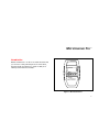
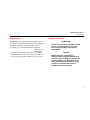
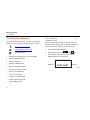
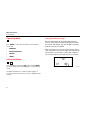
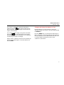
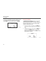
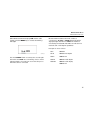
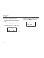
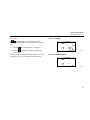
TM
MicroScanner Pro
™
Users Manual
(English)
November 2001, Rev. 2, 9/03
© 2001-2003 Fluke Corporation. All rights reserved.
All product names are trademarks of their respective companies.
LIMITED WARRANTY AND LIMITATION OF LIABILITY
Each Fluke Networks product is warranted to be free from defects in material and workmanship under normal use and service. The warranty
period is one year and begins on the date of purchase. Parts, accessories, product repairs and services are warranted for 90 days. This warranty extends only to the original buyer or end-user customer of a Fluke Networks authorized reseller, and does not apply to disposable
batteries, cable connector tabs, cable insulation-displacement connectors, or to any product which, in Fluke Networks’ opinion, has been
misused, altered, neglected, contaminated, or damaged by accident or abnormal conditions of operation or handling. Fluke Networks warrants that software will operate substantially in accordance with its functional specifications for 90 days and that it has been properly recorded on non-defective media. Fluke Networks does not warrant that software will be error free or operate without interruption.
Fluke Networks authorized resellers shall extend this warranty on new and unused products to end-user customers only but have no
authority to extend a greater or different warranty on behalf of Fluke Networks. Warranty support is available only if product is purchased
through a Fluke Networks authorized sales outlet or Buyer has paid the applicable international price. Fluke Networks reserves the right to
invoice Buyer for importation costs of repair/replacement parts when product purchased in one country is submitted for repair in another
country.
Fluke Networks’ warranty obligation is limited, at Fluke Networks’ option, to refund of the purchase price, free of charge repair, or replacement of a defective product which is returned to a Fluke Networks authorized service center within the warranty period.
To obtain warranty service, contact your nearest Fluke Networks authorized service center to obtain return authorization information, then
send the product to that service center, with a description of the difficulty, postage and insurance prepaid (FOB Destination). Fluke Networks assumes no risk for damage in transit. Following warranty repair, the product will be returned to Buyer, transportation prepaid (FOB
Destination). If Fluke Networks determines that failure was caused by neglect, misuse, contamination, alteration, accident or abnormal
condition of operation or handling, or normal wear and tear of mechanical components, Fluke Networks will provide an estimate of repair
costs and obtain authorization before commencing the work. Following repair, the product will be returned to the Buyer transportation
prepaid and the Buyer will be billed for the repair and return transportation charges (FOB Shipping Point).
THIS WARRANTY IS BUYER’S SOLE AND EXCLUSIVE REMEDY AND IS IN LIEU OF ALL OTHER WARRANTIES, EXPRESS OR IMPLIED, INCLUDING
BUT NOT LIMITED TO ANY IMPLIED WARRANTY OF MERCHANTABILITY OR FITNESS FOR A PARTICULAR PURPOSE. FLUKE NETWORKS SHALL
NOT BE LIABLE FOR ANY SPECIAL, INDIRECT, INCIDENTAL OR CONSEQUENTIAL DAMAGES OR LOSSES, INCLUDING LOSS OF DATA, ARISING
FROM ANY CAUSE OR THEORY.
Since some countries or states do not allow limitation of the term of an implied warranty, or exclusion or limitation of incidental or consequential damages, the limitations and exclusions of this warranty may not apply to every buyer. If any provision of this Warranty is held
invalid or unenforceable by a court or other decision-maker of competent jurisdiction, such holding will not affect the validity or enforceability of any other provision.
6/01
Fluke Networks
PO Box 777
Everett, WA 98206-0777
USA
Table of Contents
Title
Introduction ....................................................................................................................
Features ..........................................................................................................................
MICROSCANNER PRO Kit Content ........................................................................................
Registration.....................................................................................................................
Safety Information ..........................................................................................................
Contacting Fluke Networks .............................................................................................
Battery ............................................................................................................................
The Keypad.....................................................................................................................
Operating Mode .............................................................................................................
Calibration Mode ............................................................................................................
Setting the NVP percentage........................................................................................
Changing the Display from Meters to Feet ..................................................................
MicroScanner Pro Tests ...................................................................................................
Page
1
2
2
3
3
4
5
5
6
6
6
7
8
Length........................................................................................................................
Network Link Indicator ...........................................................................................
Pair Length.............................................................................................................
Coaxial Cabling......................................................................................................
Office Identifier...........................................................................................................
Toner ..............................................................................................................................
Technical Specifications ...................................................................................................
12
14
17
18
19
21
22
MicroScanner Pro™
Introduction
MICROSCANNER PRO™ is an all-in-one network tester that
you can use to verify twisted pair and coaxial cables,
measure length and distance to faults via TDR, and
identify active networks and hubs.
MICROSCANNER PRO
aue28f.eps
Figure 1. MicroScanner Pro
1
MicroScanner Pro
Users Manual
Features
MICROSCANNER PRO Kit Content
•
Tests unshielded twisted pair (UTP), shielded
twisted pair (SSTP) and coaxial cable
Your MICROSCANNER PRO kit contains the following:
•
Pinpoints opens, shorts, crossed and split pairs
•
Measures cable length via TDR
•
Checks and verifies wiremap
•
Generates four different tracing tones to help
identify users
•
Identifies active networking 10/100 hubs, switches,
and PCs.
2
•
1 MICROSCANNER PRO network cable tester
•
Wiremap adapter
•
COAX adapter
•
9 Volt alkaline battery
•
Quick Reference Guide
•
Product Manuals CD
MicroScanner Pro™
Registration
Registration
Registering your product with Fluke Networks gives
you access to valuable information on product updates,
troubleshooting tips, and other support services.
To register, go to the Fluke Networks website at
www.flukenetworks.com/registration and fill out the
online registration form. If you do not have Internet
access, print the registration form that is on the CD
included with the product. Fill out the form, then mail
or fax it to the appropriate address for your country.
Safety Information
WWarnings
Do not open the unit or attempt to repair
in case of malfunction. Please send it
back to your distributor for repair or
replacement.
Caution
MICROSCANNER PRO is designed to
withstand input voltage conditions that
arise from normal telephony applications
such as 48 VDC at less than 80 ma or 24
VAC used to power many keysets. Tests
cannot be performed when hazard
conditions exist on the inputs.
3
MicroScanner Pro
Users Manual
Contacting Fluke Networks
If you have technical questions, you may contact Fluke
Networks’ Technical Support by phone, fax or e-mail.
www.flukenetworks.com
Before calling Technical Support, please have your
Hardware and Software Version numbers available. To
find out the version numbers, do the following:
[email protected]
1.
Turn off the MICROSCANNER PRO.
+1-425-446-4519
2.
Simultaneously press the
•
Australia: 61 (2) 8850-3333 or 61 3 9329 0244
•
Beijing: 86 (10) 6512-3435
•
Brazil: 11 3044 1277
•
Canada: 1-800-363-5853
•
Europe: +44 1923 281 300
•
Hong Kong: 852 2721-3228
•
Japan: +81-3-3434-0181
•
Korea: 82 2 539-6311
•
Singapore: +65-6738-5655
•
Taiwan: (886) 2-227-83199
•
USA: 1-800-283-5853
4
Visit our website at www.flukenetworks.com for a
complete list of phone numbers.
,
MODE
, and
ON
OFF
keys.
The hardware and software versions of the
MICROSCANNER PRO are displayed.
Hardware
Software
aue02f.eps
MicroScanner Pro™
Battery
Battery
The Keypad
MICROSCANNER PRO requires a 9 Volt Alkaline battery.
The Battery icon is displayed on the screen when
MICROSCANNER PRO detects a low battery condition.
ON
OFF
When turned on, MICROSCANNER PRO flashes the LCD
power-up test then resumes the test mode that was
last executed. MICROSCANNER PRO turns off automatically
when no cable is detected or when no key has been
pressed for 10 minutes.
Using MICROSCANNER PRO with a low battery may effect
the test accuracy.
If MICROSCANNER PRO is stored for more than one month,
the battery should be removed.
Note
MICROSCANNER PRO will not function properly
with a 9 Volt Carbon Battery.
To quickly change pairs or adjust values, press the
keys. These keys are active only if the indicators
are shown on the display.
5
MicroScanner Pro
Users Manual
Operating Mode
MODE
Press MODE to select the desired test. The available
modes are:
•
WIREMAP
•
OFFICE IDENTIFIER
•
LENGTH
•
TONER
Setting the NVP percentage
Once in Calibrate Mode, the default NVP (Nominal
Velocity of Propagation) will be displayed followed by
the overall cable length. The cable length is measured
with the currently stored NVP.
NVP is the measure of how fast a signal travels down a
cable compared to the speed of light. The result will be
represented as a percentage of the speed of light. For
an accurate length test, the NVP must be set correctly.
Calibration Mode
MODE
+
ON
OFF
Turn the MICROSCANNER PRO OFF, then hold the MODE
key down while pressing the ON key to start Calibrate
mode.
Use MICROSCANNER PRO to calibrate cable lengths of
more than 50 feet (15 meters) and up to 1500 feet (457
meters).
6
aue01f.eps
MicroScanner Pro™
Calibration Mode
If you know a cable’s NVP, change the displayed
numbers using the
keys until the appropriate
NVP is displayed. The cable length will automatically
adjust to the new NVP.
If you know a cable’s length, change the shown NVP
using the
keys until the appropriate length is
displayed. The NVP can be adjusted in 1% increments,
and the length changes accordingly.
Cables used for calibration must be at least 50 feet (15
meters) long. Cable lengths of less than 50 feet will
display FAULT.
Changing the Display from Meters to Feet
During Calibration you will be able to switch the
displayed length from meters to feet by simply pressing
the MODE key.
Press the ON/OFF key once the desired cable length or
NVP is displayed to terminate Calibrate mode and store
the new calibration factor. MICROSCANNER PRO will use it
for future length measurements until another
calibration is performed.
7
MicroScanner Pro
Users Manual
MICROSCANNER PRO Tests
To conduct a Wiremap test:
This section describes the tests that you can conduct
with MICROSCANNER PRO.
1.
Connect the cable to be tested to the MAIN jack
(identified on the unit right above the modular 8
jack).
2.
To display the Wiremap screen, press the MODE
key until the word WIREMAP appears on the
screen.
Wiremap
The Wiremap function tests twisted-pair cabling for
proper wiring. Your cabling configuration is checked
for shield continuity, opens, shorts, crossed pairs, split
pairs, and reversed pairs.
Test Results are displayed as a numeric representation,
where the upper line of fixed digits shows the detected
wires at the MICROSCANNER PRO jack, and the lower line
of digits indicates the actual wiring. This function
requires the use of the Wiremap Adapter at the far
end.
8
MicroScanner Pro™
MicroScanner Pro Tests
Following are examples where MICROSCANNER PRO did
not detect any faults.
Token Ring unshielded shielded (2 pair, 4 wires)
Full Wiremap with intact shield shown as Zero ‘0’
on the right (4 pair, 8 wires)
aue05f.eps
aue03f.eps
10BaseT Cable unshielded (2 pair, 4 wires)
aue04f.eps
9
MicroScanner Pro
Users Manual
Below are examples of wiring faults. The FAULT
indicator will be displayed and the numerical wire
indicators will blink.
Split Pair
Reversed: Pair 3 – 6
aue08f.eps
Note
aue06f.eps
Crossed: Pairs 4 – 5, 3 – 6
aue07f.eps
10
If a cable is wired correctly, pin-to-pin, but
there is a split pair, Wiremap will display
SPLIT PAIR. For example, a wire from the
1 - 2 pair could be twisted with a wire
from the 3 - 6 pair.
MicroScanner Pro™
MicroScanner Pro Tests
If the wire does not go to the far end, the numerical
indicator for the open will be left blank. The word
Open will be displayed. Shorted pairs are indicated
with a connecting bracket, and the word Short will be
displayed.
Short: Pair 1 – 2
Open: Pair 4 – 5
aue10f.eps
When the wiring fault includes shorted or swapped
non-pair pins (e.g. non-pair pins 1 - 3), the wiremap
will display dashes for those numerical wire indicators.
aue09f.eps
Note
Shielded cross-over cables cannot be read by
MicroScanner Pro. Wiremap will show as a
series of dashes.
11
MicroScanner Pro
Users Manual
Patch Cable Wiremap
Length
The Wiremap function can also be used to verify patch
cables.
The Length function measures the full length of a
twisted pair or coaxial cable. Twisted pair: If you are
measuring standard pair length, MICROSCANNER PRO will
determine whether the cable is open, shorted, or
connected to a hub.
1.
Simply plug the two ends of a cable into the two
modular 8 jacks (MAIN and LOOP BACK) on
MICROSCANNER PRO.
2.
To display the Wiremap screen, press the MODE
key until the word WIREMAP appears on the
screen.
If there are any miswires, the number of the faulty wire
will blink.
12
Note
Accuracy of the length measurement is ± 4 %
or ±2 feet— whichever is greater. Any NVP
uncertainty is an additional error.
1.
Connect the cable to be tested to the MAIN jack
(identified on the unit right above the modular 8
jack).
MicroScanner Pro™
MicroScanner Pro Tests
2.
To display the length screen, press the MODE key
until the word LENGTH appears on the screen. The
overall cable length will be shown.
No Cable attached
If the far end of a cable is connected to a hub,
MICROSCANNER PRO will display HUB and the cable
length. The cable is considered connected to a hub
when the 3 - 6 pair is terminated and either pair 1 - 2
or 4 - 5 is terminated.
Length to Hub
aue11f.eps
aue13f.eps
70 feet cable
aue12f.eps
13
MicroScanner Pro
Users Manual
Some early model 100TX only network equipment does
not generate link pulses and MICROSCANNER PRO will
display HUB, the cable length and the word SIGNAL.
Network Link Indicator
The Network Link Indicator allows you to find and
identify active network 10/100 hubs and confirm to
which hub MICROSCANNER PRO is connected. It will blink
the hub’s status indicator to assist locating a single
channel in a busy wiring closet.
1.
Connect the cable to be tested to the MAIN jack
(identified on the unit right above the modular 8
jack).
2.
To display the length screen, press the MODE key
until the word LENGTH appears on the screen.
MICROSCANNER PRO displays the word Hub followed
by the length to the hub.
aue14f.eps
aue15f.eps
14
MicroScanner Pro™
MicroScanner Pro Tests
When MICROSCANNER PRO displays Hub and the cable
length, press the MODE key to activate the blinking
Hub light.
MICROSCANNER PRO detects the kind of hub it is
connected to: 10, 100, or 10/100 alternately will be
displayed right after the word Hub. The number is
followed by the letters F and/or H as an indication for
the hub’s full or half duplex capabilities.
Descriptions are as follows:
aue16f.eps
The word SIGNAL blinks once every two seconds right
below the word Hub. Go to the wiring closet to view a
light that blinks once every two seconds at the port to
which the cable is connected.
10 H
10BASE-T
10 HF
10BASE-T full duplex
100 H
100BASE-TX
100 HF
100BASE-T full duplex
100 HF4
100BASE-T full duplex,
100BASE-T4
15
MicroScanner Pro
Users Manual
MICROSCANNER PRO also Identifies workstations.
3.
1.
Connect the cable to be tested to the MAIN jack
(identified on the unit right above the modular 8
jack).
2.
To display the length screen, press the MODE key
until the word LENGTH appears on the screen.
MICROSCANNER PRO displays the word PC followed
by the length to the PC.
aue17f.eps
16
When MICROSCANNER PRO displays PC and the cable
length, press the MODE key to activate the
blinking Hub light.
aue18f.eps
MicroScanner Pro™
MicroScanner Pro Tests
Pair Length
Pair 1 - 2 Length
If
are displayed, you will be able to show
detailed pair information for each standard conductor
pair.
key to display Pair 1 - 2 length.
1.
Press the
2.
key again to display the other pair
Press the
combinations.
The pair length is not measured if the cable is too long,
connected to a hub, or a wiremap adapter is used.
aue19f.eps
Pair 1 - 2 not measurable
aue20f.eps
17
MicroScanner Pro
Users Manual
Coaxial Cabling
2.
Connect the cable to be tested to the COAX
adapter jack.
3.
To display the length screen, press the MODE key
until the word LENGTH appears on the screen.
Note
This feature is available when you use the
COAX upgrade kit.
MICROSCANNER PRO measures the full length of a 50
and/or 75Ω (Ohms) coaxial cable, e.g. RG-6 and
identifies its termination state.
1.
The overall cable length will be shown.
Attach the supplied COAX adapter to the MAIN
jack (identified on the unit right above the
modular 8 jack).
aue21f.eps
18
MicroScanner Pro™
MicroScanner Pro Tests
If the coaxial cable is not terminated at the far end, the
word Open will be displayed.
If a shorted cable is detected, the words FAULT and
Short will be displayed, and the length where the
short has been found.
Office Identifier
The Office Identifier function allows you to find the
termination of a twisted pair and/or a coax cable drop
from a distribution panel. By inserting the Office
Identifier adapters into wall outlets, MICROSCANNER PRO
can identify office locations at the distribution panel.
The Office Identifier plugs are included in the Office
Identifier accessory kit. They are uniquely numbered
and have RJ-45 connectors on one end and COAX
connectors on the other end to allow identification of
RJ-45 and/or COAX outlets.
aue22f.eps
19
MicroScanner Pro
Users Manual
1.
2.
Attach the coax adapter to the MAIN jack
(identified on the unit right above the modular 8
jack).
To display the Office Identifier screen, press the
MODE key until the word OFFICE is displayed on
the screen.
3.
Insert the Office Identifier plugs into wall outlets
in the offices you wish to locate.
4.
At the distribution panel, connect the cable to be
tested to the coax adapter and run the Office
Identifier function to identify which office is
connected to a given port.
MICROSCANNER PRO will display the number of the Office
Identifier found.
Note
The Wiremap adapter included with the
MicroScanner Pro has a default setting of
Office ID 4.
Office 1 found
aue25f.eps
No office found
aue26f.eps
20
MicroScanner Pro™
Toner
Toner
Toner is a cable tracing function that assists in tracking
cables hidden in walls, ceilings, floors, or patch panels
by generating four distinct multi-tone signals that can
be received by a cable tracer.
To trace a cable, use any inductive probe capable of
receiving a 1000 Hz signal, such as the Fluke Networks
MicroProbe, IntelliTone Probe, or any equivalent
tracing device to convert a signal on the cable into an
audible tone. To determine the cable path, simply trace
along the wire using the audible tone as a guide.
The tracer needs to be within one foot of the hidden
cable. You may select one of four different tone
sequences, displayed as the numbers 1-4 on the LCD.
1.
To display the Toner screen, press the MODE key
until the words SIGNAL and TONE are displayed
on the screen.
2.
To select a different tone sequence, press the
or
key.
Display for time frames with #3 signal tone
aue27f.eps
To enhance the signal insert a grounding plug into the
ground jack located next to the MAIN and LOOPBACK
jacks. You may use any grounding cable that has a
standard insulated phone tip plug.
21
MicroScanner Pro
Users Manual
Technical Specifications
Dimensions:
MICROSCANNER PRO: 13.97 cm x 8.25 cm x 2.54 cm
(5.5" x 3.25" x 1")
Wiremap Adapter: 7.62 cm x 3.18 cm x 2.11 cm
(3" x 1.25" x .83")
Office Identifier: 7.62 cm x 1.60 cm x 1.47 cm
(3" x .63" x .58")
Coax Adapter: 7.62 cm x 1.60 cm x 1.47 cm
(3" x .63" x .58")
Ground pin receptacle size:
2.03 mm (.08")
22
Weight:
MICROSCANNER PRO: 171.54 g (.38 lbs)
Wiremap Adapter/Office Identifier: 9.03 g (.02 lbs)
Power Source:
9 V Alkaline battery (NEDA-1604, IEC 6LR61)
User Interface:
Display: Custom LCD
Size: 4.42 cm x 2.15 cm (1.75" x .85")
Keypad: Four momentary contact keys
MicroScanner Pro™
Technical Specifications
Environmental:
Calibration:
Operating Temperature: 0° to 50° C (32° to 122° F)
User selectable NVP
Storage Temperature: -10° to 55° C (14° to 131° F)
NVP calculation based on known cable length
Humidity: 10 % to 90 % non-condensing
Minimum length: 15 meters (50 feet)
Applications:
Shielded and unshielded twisted pair cable, 75 or
50 ohm coaxial cable, 10 or 10/100 BASE-T
Networks
Test Interface:
Main: Modular 8 connector for length, 10/100 link
identification, wiremap, office identifier/room
identifier, trace
TDR Accuracy:
±4 % or ±2 feet whichever is greater. Any NVP
uncertainty is an additional error.
Length:
Maximum length: 450 meters (1500 feet)
Office Identifier:
Maximum length: 150 meters (500 feet)
Loopback: Modular 8 connector for patch cable
wiremap
23
MicroScanner Pro
Users Manual
24