1
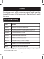
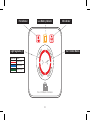
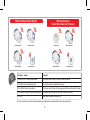
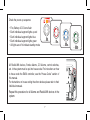
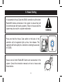
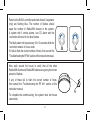
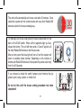
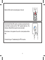
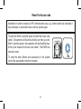
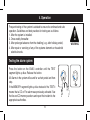
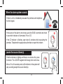
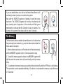
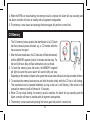
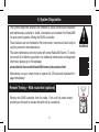
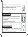
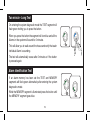
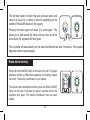
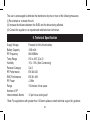
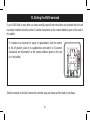
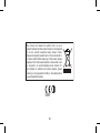
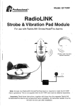
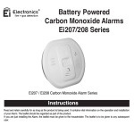
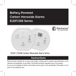
Alarm Controller
Fire and CO
Model: Ei450
Instruction Manual
Read and retain carefully for as long as the product is being used. It contains vital information on the operation and installation of your Smoke Alarm.
The leaflet should be regarded as part of the product.
If you are just installing the unit, the leaftet must be given to the householder. The leaflet is to be given to any subsequent user.
Contents
Page
1. Overview ........................................................................................................
3
2. Installation ......................................................................................................
6
3. House Coding ................................................................................................
8
4. Operation ....................................................................................................... 13
5. System Diagnostics ....................................................................................... 17
6. Five Year Guarantee ..................................................................................... 21
7. Troubleshooting the RF link .......................................................................... 22
8. Limitations of Radio Communications ........................................................... 23
9. Technical Specification .................................................................................. 24
10. Getting your Ei450 Serviced .......................................................................... 25
2
1. Overview
Congratulations on purchasing the Ei450 single button alarm controller for RadioLINK Fire and Carbon
Monoxide (CO) Alarm systems. The Ei450 tests and controls fire, CO and hybrid (Fire + CO) RadioLINK
Alarm systems.
Ei450 ἱ-controller functionality
Function
Description
Remote Test
All the Alarms can be tested from a centralised location
Remote Locate
This will silence all the Alarms in the system except the one sensing Fire or CO
Remote Silence
This will silence all the Alarms in the system
Fire Indicator
Indicates a that a Fire Alarm has been activated
CO Indicator
Indicates a that a CO Alarm has been activated
EOL Indicator
Indicates that the battery has reached its end of life (EOL)
Memory
Indicates if a Fire or CO Alarm has been previously activated
Memory ID
Identifies the Alarm that has previously been activated
Some older revisions of our RadioLINK modules do not support the Memory ID function. Check this page on our website for a complete and
accurate list of products that support this function.
3
Fire Indicator
Low Battery Indicator
Light Segments (4)
Segment Colour
CO Indicator
Test / Control Button
Activity
Function enabled
RF signal activity
Function complete
Fire / CO Alarm Controller
4
Wireless Smoke Alarm System
RF Smoke Alarm
RF Smoke Alarm
rks
Wo ith
w
Wireless Smoke &
Carbon Monoxide Alarm System
RF Smoke Alarm
RF CO Alarm
Alarm Controller
Model No. - Alarms
RF Smoke Alarm
RF Smoke Alarm
Alarm Controller
Comment
Ei160RC & Ei2110 Series Smoke Alarms
The Alarms must be fitted on Ei168RC RadioLINK bases
Ei262 Mains Carbon Monoxide Alarms
The Ei262 has built-in RadioLINK technology
Ei605 & Ei650 Series Smoke Alarms
The Alarms must be fitted with the appropriate Ei605 series RadioLINK module
Ei208 Battery Powered Carbon Monoxide Alarms
The Alarms must be fitted with Ei200MRF RadioLINK modules
Ei170RF
Deaf Alarm Strobe and Vibration Pad
For most up to date works with list check webpage www.eielectronics.com/articles/ei450-memory-id-products.html
5
2. Installation
Install the Ei450 mounting plate at an accessible point on the wall 1.4M
+/- 200mm from floor level. If it intended for a disabled person to operate
the controller, an alternative mounting location should be considered.
Also consider security and chose a location where it will not be
accidently or otherwise operated.
MODE
ON
POWER
OFF
H.CODE
Turn on the system by sliding the switch to the on position.
6
Check the power up sequence
•
•
•
•
•
Fire, Battery & CO icons flash
Each individual segment lights up red
Each individual segment lights blue
Each individual segment lights green
All lights are off to indicate standby mode
Fire / CO Alarm Controller
Fire / CO Alarm Controller
Fire / CO Alarm Controller
Repeat this procedure for all Alarms and RadioLINK devices in the
system.
7
OFF
POWER
ON
MODE
All RadioLINK devices, Smoke Alarms, CO Alarms, control switches,
etc. in the system must be put into house code. For instructions on how
to house code the Ei450 controller, see the “House Code” section of
this manual.
For instructions on house coding the other devices please refer to their
individual manuals.
H.CODE
Fire / CO Alarm Controller
3. House Coding
H.CODE
OFF
POWER
ON
Press and hold the House Code switch on the back of the
controller until all segments light up blue, then release. The
segments will flash rapidly for a moment on entering house code
(H CODE).
WARNING
MODE
It is essential to House Code the Ei450 i-controller to all the other
RadioLINK Alarms and devices in the system to ensure they will
not communicate with nearby systems. Failure to house code the
system may also result in a system malfunction.
Fire / CO Alarm Controller
House code all other RadioLINK Alarms and accessories in the
system. Consult the instruction manuals on how to house code
these devices.
8
Return to the Ei450 i-controller and check that all 4 segments
(ring) are flashing blue. The number of flashes should
equal the number of RadioLINK devices in the system.
A system with 3 smoke alarms, one CO alarm and the
i-controller will result in five blue flashes.
The flash pattern will repeat every 5 to 10 seconds while the
i-controller remains in house code.
If it fails to flash the correct number of times, then consult the
“Troubleshooting the RF link” section of this instruction manual.
Now, walk around the house to verify that all the other
RadioLINK Alarms and RadioLINK devices are giving the correct
amount of flashes.
If any of these fail to flash the correct number of times,
then consult the “Troubleshooting the RF link” section of this
instruction manual.
To complete the commissioning, the system must exit house
code mode.
9
Fire / CO Alarm Controller
Fire / CO Alarm Controller
Do not do this until the house coding procedure has been
completed!
10
OFF
POWER
ON
ON
POW
Fire / CO Alarm Controller
MODE
If you choose to make the switch tamper proof remove the pip
(plastic post) using a pliers or similar tool.
MODE
To manually exit house code press the house code button on the
back of the Ei450 switch. When all the segments light up blue,
release the button. This unit will then send a “Cancel” signal to all
the other RadioLINK devices to exit House code.
After a short period the blue light will turn off and the system will
return to standby mode (normal). Depending on the number of
Alarms and RadioLINK devices in the system this period could vary
from 5 to 20 Seconds.
H.CODE
The units will automatically exit house code after 30 minutes. Once
coded the system will not communicate with any other RadioLINK
devices outside the house coded group.
Slide the Ei450 onto the mounting base on the wall.
Fire / CO Alarm Controller
Check that the RadioLINK system is working by pressing the button
on the Ei450 i-controller until the TEST segment lights blue. This
indicates a RadioLINK test signal has been activated.
All the Alarms in the system will sound for a short period and then
stop.
If the test fails go to Troubleshooting the RF link section.
11
Fire / CO Alarm Controller
Reset the house code
To reset the other Alarms and accessories in the system
consult the appropriate instruction manuals.
12
OFF
POWER
ON
MODE
To reset the Ei450 i-controller press and hold the house code
switch. All segments will flash blue briefly and then go solid.
After 5 seconds approx. the segments will start flashing blue.
At this point release the house code switch. The Ei450 has
now been reset.
H.CODE
Sometimes in order to resolve an RF communication issue, e.g. Alarms had to be relocated, it
may necessary to reset and house code the system again.
Fire / CO Alarm Controller
4. Operation
Frequent testing of the system is advised to ensure its continued and safe
operation. Guidelines and best practices for testing are as follows:
1. After the system is installed.
2. Once weekly thereafter.
3. After prolonged absence from the dwelling (.e.g. after holiday period).
4. After repair or servicing of any of the systems elements or household electrical works.
WARNING
Testing the alarm system
Press the button on the Ei450 i-controller until the TEST
segment lights up blue. Release the button.
All Alarms in the system will sound for a short period and then
stop.
If the MEMORY segment lights up blue instead of the TEST it
means that a CO or Fire alarm was previously activated. See
the fire and CO memory sections and report the incident to the
appropriate authorities.
13
Fire / CO Alarm Controller
Fire / CO Alarm Controller
When the alarm system sounds
If there is a fire, immediately evacuate the premises and telephone
the fire brigade.
If the source of the alarm is not obvious go to the Ei450 i-controller and check
to see which indicator is illuminated, Fire or CO.
If the CO indicator is flashing, open doors & windows while evacuating the
premises. Telephone the appropriate authorities to report the incident.
Fire / CO Alarm Controller
Locate the source Alarm(s)
If the fire indicator is lighting and there is no obvious fire, press
the button. The LOCATE segment will change from red to blue.
After a 10 to 40 seconds period, all the Alarms in the system will
stop sounding except the source Alarm(s).
14
Fire / CO Alarm Controller
Fire / CO Alarm Controller
If you are satisfied there is no fire but the Smoke/Heat Alarm is still
continuing to alarm you may now silence the system.
Wait until the SILENCE segment is flashing red and then press
the button. The SILENCE segment will turn blue, the Alarm(s) will
stop sounding and all segments on the controller will flash green
momentarily to indicate that the Controller is back in standby. The
Alarms in the system will be silenced for the next 10 minutes.
Fire / CO Alarm Controller
Fire / CO Alarm Controller
Fire
Memory
The fire memory feature enables the identification of a fire Alarm that
has previously been activated, e.g. one that false alarmed when the
house was not occupied.
1. After the Alarm deactivates, the Fire indicator will flash alternatively
with the MEMORY segment (red) for 2 minutes and then stop.
2. To recall the memory press the button, the MEMORY segment will
light blue and the source alarm will sound briefly and stop several
times.
3. To reactivate the memory feature press and hold the button briefly while the FIRE Icon is still flashing.
This reactivation can be repeated indefinitely. If the button is not pressed the memory recall will timeout
in 10 seconds.
Fire / CO Alarm Controller
15
Fire / CO Alarm Controller
4. When the FIRE icon stops flashing, the memory recall is complete, the Alarm will stop sounding and
the Alarm controller will return to standby with all segments extinguished.
5. The memory is now erased and pressing the button again will perform a normal test.
CO Memory
The CO memory feature enables the identification of a CO Alarm
that has previously been activated, e.g. a CO incident while the
house was not occupied.
1. After the Alarm deactivates, the CO indicator will flash alternatively
with the MEMORY segment (red) for 2 minutes and then stop. For
the next 24h hours they will flash alternatively once a minute.
2.To recall the memory press the button, the MEMORY segment
will light blue and the source alarm will sound briefly and stop.
Depending on the number of alarms in the system the source alarm will sound and stop a number of times.
3.To reactivate the memory feature press and hold the button briefly while the CO Icon is still flashing.
This reactivation can be repeated indefinitely as long as the icon is still flashing. If the button is not
pressed the memory recall will timeout in 10 seconds.
4.When CO icon stops flashing, the memory recall is complete, the Alarm will stop sounding and the
Alarm controller will return to standby with all segments extinguished.
5.The memory is now erased and pressing the button again will perform a normal test.
Fire / CO Alarm Controller
16
Fire / CO Alarm Controller
5. System Diagnostics
The system diagnostic features are intended to assist professional installation
and maintenance personal to install, commission and maintain the RadioLINK
fire and control systems utilising the Ei450 i-controller.
These features are not intended for the home owner / tenant and should only be
used by personnel described above.
The alarm identification test only works with some RadioLINK Alarms. To check
the current list of Alarms supported or for additional maintenance and diagnostic
information please go to this webpage
www.eielectronics.com/articles/ei450-memory-id-products.html
Alternatively use your smart phone to capture this QR code and download the
page immediately.
WARNING
Remote Testing – Walk round test (optional)
Remove the Ei450 controller from its cradle. If the unit has been tamper
proofed you will need to release the latch with a screwdriver.
17
Fire / CO Alarm Controller
With the Ei450 in your hand press and hold the button. Walk around the
house and verify that each Alarm is sounding. When testing is complete
release the button and replace the controller in its cradle.
If the test fails go to Troubleshooting the RF link section.
Fire / CO Alarm Controller
System Diagnostic Mode
OFF
H.CODE
A special system diagnostic mode will facilitate the following special tests.
MODE
ON
POWER
1.Two minute “Long Test”. This is an alternative to the walk round test
described previously.
2.Identify any Alarm that been previously activated.
The procedure is used to manually exit the diagnostic. If there has been 2 minutes
of inactivity the alarm controller will automatically exit the diagnostic mode.
Enter and Exit diagnostic mode
To enter the system diagnostic mode use a small screwdriver to press and
release the MODE button on the back of the unit. All segments will flash green
to indicate that the diagnostic mode has been activated.
18
Fire / CO Alarm Controller
Two minute - Long Test
On entering the system diagnostic mode the TEST segment will
flash green inviting you to press the button.
When you press the button the segment will turn blue and all the
Alarms in the system will sound for 2 minutes.
This will allow you to walk around the house and verify that each
individual Alarm is sounding.
Fire / CO Alarm Controller
Fire / CO Alarm Controller
The test will automatically cease after 2 minutes or if the button
is pressed again.
Alarm Identification Test
If an alarm memory has been set the TEST and MEMORY
segments will flash green alternatively after entering the system
diagnostics mode.
While the MEMORY segment is illuminated press the button until
the MEMORY segment goes blue.
19
Fire / CO Alarm Controller
Fire / CO Alarm Controller
Fire / CO Alarm Controller
Fire / CO Alarm Controller
This will then locate the Alarm that was previously active and
cause it to sound for a number of seconds (depending on the
number of RadioLINK devices in the system).
Pressing the button again will cause it to sound again. This
allows you to walk around the house until you have found the
active Alarm. All segments will flash green.
Fire / CO Alarm Controller
Fire / CO Alarm Controller
The i-controller will automatically exit the alarm identification test after 2 minutes or if the system
diagnostic button is pressed again.
To erase the alarm identification memory press and hold the MODE
button on the back of the alarm for about 6 seconds until all the
segments flash green. The memory identification has now been
erased.
20
OFF
POWER
MODE
ON
Press and hold the MODE switch on the back of the unit. The green
segments will light up. When these segments start flashing, release
the button. The memory identification is now cleared.
H.CODE
Erase alarm memory
Fire / CO Alarm Controller
6. Guarantee
Ei Electronics guarantees the (‘Model Ei450’) for 5 years from date of purchase against any defects
that are due to faulty materials or workmanship. This guarantee excludes replaceable batteries.
This guarantee only applies to normal conditions of use and service and does not include damage
resulting from accident, neglect, misuse, unauthorised dismantling, or contamination howsoever
caused. This guarantee excludes incidental and consequential damage.
This guarantee does not cover costs associated with the removal and/or installation of units.
If the product should become defective within the guarantee period, it may be returned with proof of
purchase, carefully packaged, and with the problem clearly stated to the place of purchase or phone
one of these numbers for advice.
UK:
0870 758 4001
ROI: +353 61 471277
We shall at our discretion repair or replace the faulty unit.
21
7. Troubleshooting the RadioLINK
If, when checking the RadioLINK interconnection, some of the Alarms do not respond to the Ei450
remote control test, then:
(i) Ensure the Ei450 controller has been activated correctly. Check that the power on procedure
operates as described in the installation section.
(ii) Repeat House Code procedure (see section 2).
(iii) Relocate the Ei450 controller and/or rotate/relocate the RadioLINK Alarms. There are a number
of reasons why the RadioLINK signals may not reach all the Alarms in your system (see section 6 on
“Limitations of Radio Frequency Signals”). Try rotating the units or relocating the units (e.g. move them
away from metal surfaces or wiring) as this can significantly improve signal reception.
Rotating and/or relocating the units may move them out of the range of existing units even though
they may have already been House Coded correctly in the system. It is therefore important to check
that all Alarms are communicating in their final installed positions. If units are rotated and/or relocated,
we recommend that all units are returned to the factory settings (see the respective use and care
instructions).Then House Code all units again in their final positions. The RadioLINK interconnection
should then be checked again.
22
8. Limitations of Radio Communications
Ei Electronics radio communication systems are very reliable and are tested to high standards.
However, due to their low transmitting power and limited range (required by regulatory bodies) there
are some limitations to be considered:
(i) Radio equipment, such as the Ei450 controller, should be tested regularly - at least weekly. This
is to determine whether there are sources of interference preventing communication. The radio paths
may be disrupted by moving furniture or renovations, and so regular testing will help identify these and
other faults, so that they can be rectified (see Section 5).
(ii) Receivers may be blocked by radio signals occurring on or near their operating frequencies,
regardless of the House Coding. The Ei450 i-controller has been tested to EN 300 220-1 V1.3.1
(2000-09) in accordance with the requirements of EN 300 220V1.1.1 (2000-09). These tests are
designed to provide reasonable protection against harmful interference in residential installations. This
equipment generates, uses and can radiate radio frequency energy and, if not installed and used in
accordance with the instructions, may cause interference to radio and/or television reception.
However, there is no guarantee that interference will not occur in a particular installation. If the Ei450
controller does cause such interference, it can be verified by turning it on and off.
23
The user is encouraged to eliminate the interference by one or more of the following measures:
(i) Re-orientate or re-locate the unit.
(ii) Increase the distance between the Ei450 and the device being affected.
(iii) Consult the supplier or an experienced radio/television technician.
9. Technical Specification
Supply Voltage
Battery Capacity
RF Frequency
Temp Range
Humidity
Receiver Category
RF Performance
EMC Performance
RF Power
Range
Number of RF
interconnected Alarms
Powered for life Lithium battery
1600 mAh
868.499Mhz
0oC to 40oC (Cat 3)
15% - 95% (Non Condensing)
Cat 2
EN 300-220
EN 301-489
+7dBm
150 meters in free space
12 per house code group*
*Note: For applications with greater than 12 Alarms please contact technical support for guidance.
24
10. Getting the Ei450 serviced
OFF
POWER
MODE
ON
If it needs to be returned for repair or replacement, slide the switch
to the off position, place it in a padded box and send it to “Customer
Assistance and Information” at the nearest address given on the unit
or in this leaflet.
H.CODE
If your Ei450 fails to work after you have carefully read all the instructions and checked that the unit
has been installed correctly contact Customer Assistance at the nearest address given at the end of
this leaflet.
State the nature of the fault, where the controller was purchased and the date of purchase.
25
Block E1
The crossed out wheelie bin symbol that is on your
product indicates that this product should not be disposed
of via the normal household waste stream. Proper
disposal will prevent possible harm to the environment or
to human health. When disposing of this product please
separate it from other waste streams to ensure that it can
be recycled in an environmentally sound manner. For
more details on collection and proper disposal, please
contact your local government office or the retailer where
you purchased this product.
0889
26
27
Aico Ltd
Mile End Business Park,
Maesbury Road, Oswestry,
Shropshire SY10 8NN, U.K.
Telephone: 0870 7584000
www.aico.co.uk
Ei Electronics
Shannon Industrial Estate,
Shannon, Co. Clare, Ireland.
Telephone: +353 (0)61 471277
www.eielectronics.com
© Ei Electronics 2012
P/N B17493 Rev 0