1
OPERATION MANUAL
Be sure to read this manual for safe and
proper operation.
Store this manual carefully after use.
Thank you for purchasing a Yanmar Marine Diesel Engine.
[ INTRODUCTION ]
• This Operation Manual describes the operation, maintenance and inspection, and handling precautions for the 4JH3-TE/-TCE/-HTE/-DTE Yanmar Marine Diesel Engine.
1. FOR SAFE OPERATION
: Safety indications, safety precautions, explanation and use.
2. EXPLANATION OF PRODUCT : Specifications for this series and basic operation principles.
3. PREPARATION FOR OPERATION : Fuel oil, lube oil, cooling water, etc. check and supply.
4. OPERATION
: Starting, speed adjusting, stopping and long-term storage.
5. MAINTENANCE & INSPECTION : Periodic inspection, inspection items and time period,
and detailed explanation.
6. TROUBLE AND TROUBLESHOOTING : Simple troubles and table of troubleshooting meaures.
• Read this Operation Manual carefully before operating the engine to ensure that it is
used correctly and that it stays in the best possible condition.
• Keep this Operation Manual in a convenient place for easy access.
• If this Operation Manual is lost or damaged, order a new one from your dealer or distributor.
• If giving your engine to someone else, be sure to attach this Operation Manual.
• Constant efforts are made to improve the quality and performance of Yanmar products, so some details included in this Operation Manual may differ slightly from your
engine. If you have any questions about this, please contact your Yanmar dealer or
distributor.
California
Proposition 65 Warning
California
Proposition 65 Warning
Diesel engine exhaust and some of its
constitutions are known to the State of
California to cause cancer, birth defects,
and other reproductive harm.
Battery posts, terminals,and related
accessories contain lead and lead
compounds, chemicals knouw to the
State of California to cause cancer
and reproductive harm.
INDEX
page No.
1 FOR SAFE OPERATION . . . . . . . . . . . . . . . . . . . . . . . . . . . . . . . . . . . . . . . . . . . . . . . . . 1
1.1 Warning Symbols . . . . . . . . . . . . . . . . . . . . . . . . . . . . . . . . . . . . . . . . . . . . . . . . . . . . . . . . . . . . . . . . . 1
1.2 Safety Precautions . . . . . . . . . . . . . . . . . . . . . . . . . . . . . . . . . . . . . . . . . . . . . . . . . . . . . . . . . . . . . . . . 2
1.3 Location of Product Safety Labels . . . . . . . . . . . . . . . . . . . . . . . . . . . . . . . . . . . . . . . . . . . . . . . . . . . . 4
2 PRODUCT EXPLANATION . . . . . . . . . . . . . . . . . . . . . . . . . . . . . . . . . . . . . . . . . . . . . . . 5
2.1 Use & Driving System . . . . . . . . . . . . . . . . . . . . . . . . . . . . . . . . . . . . . . . . . . . . . . . . . . . . . . . . . . . . . 5
2.2 Engine Specifications . . . . . . . . . . . . . . . . . . . . . . . . . . . . . . . . . . . . . . . . . . . . . . . . . . . . . . . . . . . . . . 6
2.2.1 4JH3-TE . . . . . . . . . . . . . . . . . . . . . . . . . . . . . . . . . . . . . . . . . . . . . . . . . . . . . . . . . . . . . . . . . . . . . . . . 6
2.2.2 4JH3-TCE . . . . . . . . . . . . . . . . . . . . . . . . . . . . . . . . . . . . . . . . . . . . . . . . . . . . . . . . . . . . . . . . . . . . . . . 7
2.2.3 4JH3-HTE . . . . . . . . . . . . . . . . . . . . . . . . . . . . . . . . . . . . . . . . . . . . . . . . . . . . . . . . . . . . . . . . . . . . . . . 8
2.2.4 4JH3-DTE . . . . . . . . . . . . . . . . . . . . . . . . . . . . . . . . . . . . . . . . . . . . . . . . . . . . . . . . . . . . . . . . . . . . . . . 9
2.3 Names of Parts . . . . . . . . . . . . . . . . . . . . . . . . . . . . . . . . . . . . . . . . . . . . . . . . . . . . . . . . . . . . . . . . . 10
2.4 Major Servicing Parts . . . . . . . . . . . . . . . . . . . . . . . . . . . . . . . . . . . . . . . . . . . . . . . . . . . . . . . . . . . . . 11
2.5 Operation Equipment . . . . . . . . . . . . . . . . . . . . . . . . . . . . . . . . . . . . . . . . . . . . . . . . . . . . . . . . . . . . . 12
2.5.1 Instrument Panel . . . . . . . . . . . . . . . . . . . . . . . . . . . . . . . . . . . . . . . . . . . . . . . . . . . . . . . . . . . . . . . . . 12
2.5.2 Remote Control Handle . . . . . . . . . . . . . . . . . . . . . . . . . . . . . . . . . . . . . . . . . . . . . . . . . . . . . . . . . . . . 15
3 BEFORE OPERATION . . . . . . . . . . . . . . . . . . . . . . . . . . . . . . . . . . . . . . . . . . . . . . . . . 18
3.1 Fuel Oil, Lube Oil and Cooling Water . . . . . . . . . . . . . . . . . . . . . . . . . . . . . . . . . . . . . . . . . . . . . . . . 18
3.1.1 Fuel Oil . . . . . . . . . . . . . . . . . . . . . . . . . . . . . . . . . . . . . . . . . . . . . . . . . . . . . . . . . . . . . . . . . . . . . . . . 18
3.1.2 Lube oil . . . . . . . . . . . . . . . . . . . . . . . . . . . . . . . . . . . . . . . . . . . . . . . . . . . . . . . . . . . . . . . . . . . . . . . . 19
3.1.3 Cooling Water . . . . . . . . . . . . . . . . . . . . . . . . . . . . . . . . . . . . . . . . . . . . . . . . . . . . . . . . . . . . . . . . . . . 19
3.2 Supplying Fuel . . . . . . . . . . . . . . . . . . . . . . . . . . . . . . . . . . . . . . . . . . . . . . . . . . . . . . . . . . . . . . . . . . 20
3.2.1 Filling the Fuel Tank . . . . . . . . . . . . . . . . . . . . . . . . . . . . . . . . . . . . . . . . . . . . . . . . . . . . . . . . . . . . . . 20
3.2.2 Bleeding the Fuel System . . . . . . . . . . . . . . . . . . . . . . . . . . . . . . . . . . . . . . . . . . . . . . . . . . . . . . . . . . 20
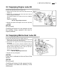
3.3 Supplying Engine Lube Oil . . . . . . . . . . . . . . . . . . . . . . . . . . . . . . . . . . . . . . . . . . . . . . . . . . . . . . . . . 21
3.4 Supplying Marine Gear Lube Oil . . . . . . . . . . . . . . . . . . . . . . . . . . . . . . . . . . . . . . . . . . . . . . . . . . . . 21
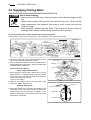
3.5 Supplying Cooling Water . . . . . . . . . . . . . . . . . . . . . . . . . . . . . . . . . . . . . . . . . . . . . . . . . . . . . . . . . . 22
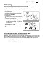
3.6 Cranking . . . . . . . . . . . . . . . . . . . . . . . . . . . . . . . . . . . . . . . . . . . . . . . . . . . . . . . . . . . . . . . . . . . . . . . 23
3.7 Checking the Lube Oil and Cooling Water . . . . . . . . . . . . . . . . . . . . . . . . . . . . . . . . . . . . . . . . . . . . . 23
4 HOW TO OPERATE . . . . . . . . . . . . . . . . . . . . . . . . . . . . . . . . . . . . . . . . . . . . . . . . . . . 24
4.1 Inspection Before Starting . . . . . . . . . . . . . . . . . . . . . . . . . . . . . . . . . . . . . . . . . . . . . . . . . . . . . . . . . 24
4.2 Checking the Illumination Lamps of the Panel Meters . . . . . . . . . . . . . . . . . . . . . . . . . . . . . . . . . . . . 26
4.2.1 Checking the Illumination Lamps of the Panel Meters . . . . . . . . . . . . . . . . . . . . . . . . . . . . . . . . . . . . 26
4.2.2 Checking the Alarm Devices . . . . . . . . . . . . . . . . . . . . . . . . . . . . . . . . . . . . . . . . . . . . . . . . . . . . . . . . 26
4.2.3 Checking the Panel Meters . . . . . . . . . . . . . . . . . . . . . . . . . . . . . . . . . . . . . . . . . . . . . . . . . . . . . . . . . 26
4.3 starting . . . . . . . . . . . . . . . . . . . . . . . . . . . . . . . . . . . . . . . . . . . . . . . . . . . . . . . . . . . . . . . . . . . . . . . . 27
4.3.1 Daily Starting . . . . . . . . . . . . . . . . . . . . . . . . . . . . . . . . . . . . . . . . . . . . . . . . . . . . . . . . . . . . . . . . . . . . 27
4.3.2 Starting Under Low Temperature Conditions . . . . . . . . . . . . . . . . . . . . . . . . . . . . . . . . . . . . . . . . . . . 27
4.3.3 Restarting After Starting Failure . . . . . . . . . . . . . . . . . . . . . . . . . . . . . . . . . . . . . . . . . . . . . . . . . . . . . 27
4.3.4 After the Engine has Started . . . . . . . . . . . . . . . . . . . . . . . . . . . . . . . . . . . . . . . . . . . . . . . . . . . . . . . . 28
4.4 Adjusting the Engine Speed . . . . . . . . . . . . . . . . . . . . . . . . . . . . . . . . . . . . . . . . . . . . . . . . . . . . . . . . 28
4.5 Clutch Operation for the Marine Gear . . . . . . . . . . . . . . . . . . . . . . . . . . . . . . . . . . . . . . . . . . . . . . . . 29
4.5.1 Forward, Neutral, Reverse . . . . . . . . . . . . . . . . . . . . . . . . . . . . . . . . . . . . . . . . . . . . . . . . . . . . . . . . . 29
4.5.2 Switching to Trawling (Available for KMH4A only) . . . . . . . . . . . . . . . . . . . . . . . . . . . . . . . . . . . . . . . 29
4.6 Check During Operation . . . . . . . . . . . . . . . . . . . . . . . . . . . . . . . . . . . . . . . . . . . . . . . . . . . . . . . . . . 30
4.7 Stopping the Engine . . . . . . . . . . . . . . . . . . . . . . . . . . . . . . . . . . . . . . . . . . . . . . . . . . . . . . . . . . . . . . 31
4.8 Operation Procedure . . . . . . . . . . . . . . . . . . . . . . . . . . . . . . . . . . . . . . . . . . . . . . . . . . . . . . . . . . . . . 32
4.9 Long-Term Storage . . . . . . . . . . . . . . . . . . . . . . . . . . . . . . . . . . . . . . . . . . . . . . . . . . . . . . . . . . . . . . 33
4.9.1 Before storing for long periods of time, perform the following. . . . . . . . . . . . . . . . . . . . . . . . . . . . . . . 33
4.9.2 Checking the Engine for Reuse After a Long Storage Period . . . . . . . . . . . . . . . . . . . . . . . . . . . . . . . 34
5 MAINTENANCE & INSPECTION . . . . . . . . . . . . . . . . . . . . . . . . . . . . . . . . . . . . . . . . . 35
5.1 List of Periodic Inspections . . . . . . . . . . . . . . . . . . . . . . . . . . . . . . . . . . . . . . . . . . . . . . . . . . . . . . . . 36
5.2 Periodic Inspection Items . . . . . . . . . . . . . . . . . . . . . . . . . . . . . . . . . . . . . . . . . . . . . . . . . . . . . . . . . . 37
5.2.1 Inspection After Initial 50Hrs. Operation . . . . . . . . . . . . . . . . . . . . . . . . . . . . . . . . . . . . . . . . . . . . . . . 37
5.2.2 Inspection Every 50 Hours . . . . . . . . . . . . . . . . . . . . . . . . . . . . . . . . . . . . . . . . . . . . . . . . . . . . . . . . . 39
5.2.3 Inspection Every 250 Hrs. or 1 yr. . . . . . . . . . . . . . . . . . . . . . . . . . . . . . . . . . . . . . . . . . . . . . . . . . . . . 41
5.2.4 Inspection Every 500 Hrs.or 2 yrs. . . . . . . . . . . . . . . . . . . . . . . . . . . . . . . . . . . . . . . . . . . . . . . . . . . . 44
5.2.5 Inspection Every 1000 Hrs. or 4 yrs. . . . . . . . . . . . . . . . . . . . . . . . . . . . . . . . . . . . . . . . . . . . . . . . . . . 45
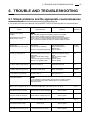
6 TROUBLE AND TROUBLESHOOTING . . . . . . . . . . . . . . . . . . . . . . . . . . . . . . . . . . . . 47
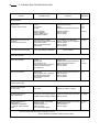
6.1 Simple problems and the appropriate countermeasures . . . . . . . . . . . . . . . . . . . . . . . . . . . . . . . . . . 47
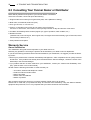
6.2 Emergency Repairs for Marine Gear Trouble . . . . . . . . . . . . . . . . . . . . . . . . . . . . . . . . . . . . . . . . . . 49
6.3 Consulting Your Yanmar Dealer or Distributor . . . . . . . . . . . . . . . . . . . . . . . . . . . . . . . . . . . . . . . . . . 50
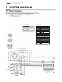
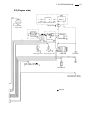
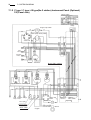
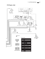
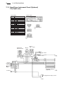
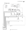
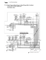
7 SYSTEM DIAGRAM . . . . . . . . . . . . . . . . . . . . . . . . . . . . . . . . . . . . . . . . . . . . . . . . . . . . 52
7.1 Wiring diagram . . . . . . . . . . . . . . . . . . . . . . . . . . . . . . . . . . . . . . . . . . . . . . . . . . . . . . . . . . . . . . . . . . 52
7.1.1 B type Instrument Panel . . . . . . . . . . . . . . . . . . . . . . . . . . . . . . . . . . . . . . . . . . . . . . . . . . . . . . . . . . . 52
7.1.2 C type / C type × B type(No.2 station) Instrument Panel . . . . . . . . . . . . . . . . . . . . . . . . . . . . . . . . . . 54
7.1.3 New B type Instrument Panel . . . . . . . . . . . . . . . . . . . . . . . . . . . . . . . . . . . . . . . . . . . . . . . . . . . . . . . 56
7.1.4 New C type / New C type × New B type(No.2 station) . . . . . . . . . . . . . . . . . . . . . . . . . . . . . . . . . . . . 58
7.1.5 Instrument Panel . . . . . . . . . . . . . . . . . . . . . . . . . . . . . . . . . . . . . . . . . . . . . . . . . . . . . . . . . . . . . . . . 58
1. FOR SAFE OPERATION
1
1. FOR SAFE OPERATION
Following the precautions described in this manual will enable you to use this engine with
complete satisfaction. Failure to observe any of the rules and precautions, however, may
result in injury, burns, fires, and engine damage. Read this manual carefully and be sure
you fully understand it before beginning operation.
1.1 Warning Symbols
These are the warning signs which are used in this manual and on the products.
Pay special attention to them.
DANGER- Indicates an imminently hazardous situation which, if
not avoided, WILL result in death or serious injury.
WARNING- Indicates a potentially hazardous situation which, if
not avoided, COULD result in death or serious injury.
CAUTION- Indicates a potentially hazardous situation which, if
not avoided, MAY result in minor or moderate injury. It may also
be used to alert against unsafe practices.
• The descriptions captioned by NOTICE are for the particularly important cautions for handling. If you ignore them, the performance of your machine may deteriorate leading to
trouble.
2
1. FOR SAFE OPERATION
1.2 Safety Precautions
(Observe these instructions for your own safety.)
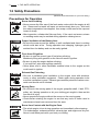
Precautions for Operation
Burns from Scalding
• Never remove the filler cap of the fresh water cooler while the engine is still
hot. Steam and hot water will spurt out and seriously burn you. Wait until
the water temperature has dropped, then wrap a cloth around the cap and
loosen it slowly.
• After inspection, refasten the filler cap firmly. If the cap is not secure, steam
or scalding water may be emitted during operation causing burns.
Proper Ventilation of the Battery Area
• Be sure the area around the battery is well-ventilated and there is nothing
which could start a fire. During operation and charging, hydrogen gas is
emitted from the battery and can be easily ignited.
Fires from Oil lgnition
• Be sure to use the correct type of fuel when refueling.
Mistakenly filling with gasoline or the like will result in ignition.
• Be sure to stop the engine before refueling.
If you spill fuel, wipe such spillage carefully.
• Never place oils or other flammable material close to the engine as this
could result in ignition.
Exhaust Gas Poisoning
• Be sure to establish good ventilation in the engine room with windows,
vents, or other ventilation equipment. Check again during operation to be
sure that ventilation is good. Exhaust gas contains poisonous carbon monoxide and should not be inhaled.
Moving Parts
• Do not touch the moving parts of the engine (propeller shaft, V-belt, PTOpulley, etc.) during operation or let your clothing get caught in them as this
can result in injury.
• Never operate the engine without the covers on the moving parts.
• Check before starting the engine to see that any tools or cloths used in
maintenance have been removed from the area.
Burns from Contact with Hot Engine Parts
• The whole engine is hot during operation and immediately after stopping.
The turbocharger, exhaust manifold, exhaust pipe, and engine are very hot.
Never touch these parts with your body or clothing.
1. FOR SAFE OPERATION
3
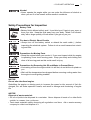
Alcohol
• Never operate the engine while you are under the influence of alcohol or
when you are ill or feel unwell as this results in accidents.
Safety Precautions for Inspection
Battery Fluid
• Battery fluid is diluted sulfuric acid. It can blind you if it gets in your eyes, or
burn your skin. Keep the fluid away from your body. Wash it off immediately with a large quantity of fresh water if you get any on you.
Fire due to Electric Short-Circuits
• Always turn off the battery switch or detach the earth cable (-) before
inspecting the electrical system. Failure to do so could cause short-circuiting and fires.
Precautions for Moving Parts
• Stoop the engine before you service it. If you must inspect while the engine
is operating, never touch moving parts. Keep your body and clothing well
clear of all moving parts as this could result in injury.
Precautions for Removing Hot Oil and Water to Prevent Burns
• If extracting oil from the engine while it is still hot, do not let the oil splash on
you.
• Wait until the temperature has dropped before removing cooling water from
the engine to avoid getting scalded.
NOTICE:
Do not alter the diesel engine.
Rebuilding the engine or altering parts to increase the speed or the amount of fuel discharged, etc. will make operation unsafe, and result in damage and shortening of engine
life.
NOTICE:
Disposal of waste materials
• Put oil or liquids to be disposed in a container. Never dispose of waste oil or other fluids
outside, in a sewer, river, or the sea.
• Treat waste materials safely observing all regulations and laws. Ask a waste recovery
company to collect and dispose of it.
4
1. FOR SAFE OPERATION
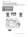
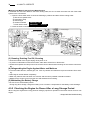
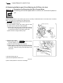
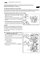
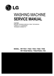
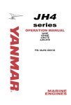
1.3 Location of Product Safety Labels
To insure safe operation, product safety labels have been attached. Their location is shown in the diagram
below. Keep the labels from becoming dirty or torn and replace them if they are lost or damaged. Also
replace labels when parts are replaced, ordering them in the same way as for the parts.
Product Safety Labels, Parts Code Numbers
1
128377-07350
2
128296-07260
3
128296-07300
4
196630-12980
The above diagram shows a side view of the engine.
2. PRODUCT EXPLANATION
5
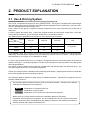
2. PRODUCT EXPLANATION
2.1 Use & Driving System
This is light, compact diesel elngine for use in pleasure boats. The engine is equipped with a turbocharger
and intercooler which insures maximum output while preserving lightness and compact size. (The 4JH3-TE /TCE are equipped with the turbocharger only.)
Power output for this group of engines increases progressively from 4JH3-TE(4JH3-TCE), 4JH3-THE to
4JH3-DTE.
In case of engine with marine gear. connect the propeller shaft to the marine gear output shaft. The 4JH3TCE is with drive SD40-4T. For the sail drive, please refer to its operation manual.
The different types of applicable marine gears for each engine are shown below.
Engine
4JH3-TE
4JH3-THE
4JH3-DTE
KBW21
O
O
×
KM4A
O
O
×
KMH4A
O
O
O
Note
Marine gear
O : Applicable
× : Not applicable
The installation, fitting and surveying of this engine all require specialized knowledge and engineering skills.
Additionally, boat and engine inspection may be required by the laws of some countries. Consult Yanmar’s
local subsidiary in your region or your distributor or dealer.
In order to get full performance from your engine, it is imperative that the size and structure of the boat be
suited to the engine. It is equally important to use the correct driving device and a propeller of the appropriate
size and specifications.
The engine must be installed correctly with safe cooling water and exhaust piping and electrical wiring. The
PTO work should be easy to use for onboard equipment.
Consult your Yanmar dealer or distributor when selecting optional parts. Optional parts selections should take
into account operational and surrounding conditions.
This Operation Manual explains the basic points for standard operation. Variations are explained under the
specially marked sections.
This operation Manual explains the basic points for standard operation. Variations are explained
under the leter emblems for easy reference.
MODEL
: Explanation of indicated model only.
OPTION
: Explanation of optional parts.
CUSTOMER : Explanation of use of parts from other boat manufacturers.
Where there are no leter emblem sections the explanation applies to all models.
Explanation for driving devices, propellers, etc. and optional parts are not included, and special
attention should be paid to the explanations and safety precautions in the operation manuals provided by the boat and equipment manufacturers.
6
2. PRODUCT EXPLANATION
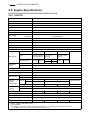
2.2 Engine Specifications
2.2.1 4JH3-TE
Engine model
4JH3-TE
Use
Pleasure boat
Type
Vertical water-cooled 4-cycle diesel engine
No. of cyl.-bore×stroke
4-φ84×90
Displacement
L
1.995
Aspiration
Turbooharged
Cont. rating
kW{hp}/rpm
50.7(69) / 3700
Max. output
kW{hp}/rpm
(Crankshaft)
*55.2(75)/3800
**53.5(72.8)/3800
High idling
rpm
4300±25
Low idling
rpm
700±25
Combustion system
Direct injection
Starting system
Electric starting
Cooling system
Constant high temperature fresh water cooling
Lubricating system
Forced lubrication system with trochoid pump
Marine gear
Direction of
rotation
Model
KBW21
KM4A
Type
Mechanical wet multiple
disk clutch input/output
eccentric parallel drive
Reduction ratio
(Ahead/Astern)
2.17/3.06
2.62/3.06
Crankshaft
KMH4A
Mechanical wet cone
clutch 7° Down
angle drive
Hydraulic wet multiple
disk clutch 8° Down
angle drive
1.47/1.47
2.14/2.14
2.63/2.63
3.30/3.30
2.04/2.04
-
2.45/2.45
Counterclockwise (Viewed from stern side)
Propeller shaft
Clockwise (Viewed from stern side)
Fuel injection pump
Bosh-distributor type Model VE(ZEXEL)
Fuel injection valve
Pinhole injection nozzle YDLLA-P(5-0.22×150°)
Turbocharger
Elec. devices
Lube oil
L
capacity
(raked angle)
Cooling water
capacity
L
RHB52(IHI) Water cooled and forced lubrication system
Starter
DC12V-1.4kW
Alternator
Engine
DC12V-55A
Oilpan
5.2(7°)
6.4(0°)
All
6.3(7°)
7.5(0°)
Marine gear
1.2
1.3
Fresh water tank
6.0
Subtank
0.8
Dimensions (L×W×H)
mm
898×560×635
Engine installation style
888×565×635
Refer to the left
2.0
-
886×565×635
763×566×635
On the flexible rubber engine mount
Recommended battery capacity
12V-120A or greater
Recommended engine room ventilator
12m3/min or greater
Dry mass
kg
249
247
250
Note:
1. Rating condition : ISO 3046-1, 8665
2. 1hp=0.7355kW
3. Fuel condition : Density at 15°C=0.860,Fuel oil temperature
*:25°C at the fuel injection pump inlet
** : ISO 8665(Fuel oil temp. 40°C at the fuel injection pump inlet)
219
2. PRODUCT EXPLANATION
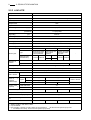
2.2.2 4JH3-TCE
Engine model
4JH3-TCE
Use
Pleasure boat (Sailing boat)
Type
Vertical water-cooled 4-cycle diesel engine
No. of cyl.-bore×stroke
mm
Displacement
L
Aspiration
4-φ84×90
1.995
Turbooharged
Cont. rating
kW{hp}/rpm
50.7(69)/3700
Max. output
kW{hp}/rpm
(Crankshaft)
*55.2(75)/3800
**53.5(72.8)/3800
High idling
rpm
4300±25
Low idling
rpm
700±25
Combustion system
Direct injection
Starting system
Electric starting
Cooling system
Constant high temperature fresh water cooling
Lubricating system
Forced lubrication system with trochoid pump
Sail drive
Model
SD40-4T
Type
Mechanical wet cone clutch
Reduction ratio
Direction of
rotation
Refer to the operation manual for the sail drive
Crankshaft
Counterclockwise(Viewed from stern side)
Propeller
Refer to the operation manual for the sail drive
Fuel injection pump
Bosh-distributor type Model VE(ZEXEL)
Fuel injection valve
Pinhole injection nozzle YDLLA-P(5-0.22×150°)
Turbocharger
RHB52(IHI) Water cooled and forced lubrication system
Starter
DC12V-1.4kW
Elec. devices
Alternator
Lube oil
L
capacity
(raked angle)
DC12V-55A
Oilpan
6.4 (Raked angle 0°)
All
7.5 (Raked angle 0°)
Engine
Drive
Refer to the operation manual for the sail drive
Fresh water tank
Cooling water
capacity
L Subtank
Dimensions (L×W×H)
6.0
0.8
mm
Engine installation style
1086×565×1238(Propeller shaft center)
On the flexible nubber engine mount
Recommended battery capacity
12V-120A or greater
Recommended engine room ventilator
12m3/min or greater
Dry mass
kg
219(Engine)
Note:
1. Rating condition : ISO 3046-1, 8665
2. 1hp=0.7355kW
3. Fuel condition : Density at 15°C=0.860,Fuel oil temperature
*:25°C at the fuel injection pump inlet
** : ISO 8665(Fuel oil temp. 40°C at the fuel injection pump inlet)
7
8
2. PRODUCT EXPLANATION
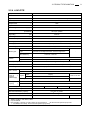
2.2.3 4JH3-HTE
Engine model
4JH3-HTE
Use
Pleasure boat
Type
Vertical water-cooled 4-cycle diesel engine
No. of cyl.-bore×stroke
4-φ84×90
mm
Displacement
L
1.995
Aspiration
Turbooharged
Cont. rating
kW{hp}/rpm
67.7(92)/3700
Max. output
kW{hp}/rpm
(Crankshaft)
*73.6(100)/3800
**71.4(97)/3800
High idling
rpm
4300±25
Low idling
rpm
700±25
Combustion system
Direct injection
Starting system
Electric starting
Cooling system
Constant high temperature fresh water cooling
Lubricating system
Forced lubrication system with trochoid pump
Model
KBW21
KMH4A
Mechanical wet multiple Mechanical wet cone
disk clutch input/output clutch 7° Down
eccentric parallel drive angle drive
Type
Marine gear
Reduction ratio
(Ahead/Astern)
Direction of
rotation
KM4A
2.17/3.06
1.47/1.47
2.14/2.14
2.63/2.63
3.30/3.30
2.62/3.06
Crankshaft
Hydraulic wet multiple
disk clutch 8° Down
angle drive
2.04/2.04
-
2.45/2.45
Counterclockwise (Viewed from stern side)
Propeller shaft
Clockwise (Viewed from stern side)
-
Fuel injection pump
Bosh-distributor type Model VE(ZEXEL)
Fuel injection valve
Pinhole injection nozzle YDLLA-P(5-0.25×150°)
Turbocharger
RHB52(IHI) Water cooled and forced lubrication system
Starter
DC12V-1.4kW
Elec. devices
Alternator
DC12V-55A
Oilpan
5.2(7°)
6.4(0°)
All
6.3(7°)
7.5(0°)
Lube oil
L
capacity
(raked angle)
Engine
Cooling water
capacity
L
Fresh water tank
7.2
Subtank
0.8
Marine gear
Dimensions (L×W×H)
1.2
mm
898×581×660
Engine installation style
1.3
888×580×660
Refer to the left
2.0
-
886×581×635
763×581×660
On the flexible rubber engine mount
Recommended battery capacity
12V-120A or greater
Recommended engine room ventilator
16m3/min or greater
Dry mass
kg
258
256
259
Note:
1. Rating condition : ISO 3046-1, 8665
2. 1hp=0.7355kW
3. Fuel condition : Density at 15°C=0.860,Fuel oil temperature
*:25°C at the fuel injection pump inlet
** : ISO 8665(Fuel oil temp. 40°C at the fuel injection pump inlet)
228
2. PRODUCT EXPLANATION
9
2.2.4 4JH3-DTE
Engine model
4JH3-DTE
Use
Pleasure boat
Type
Vertical water-cooled 4-cycle diesel engine
No. of cyl.-bore×stroke
4-φ84×90
mm
Displacement
L
1.995
Aspiration
Turbooharged
Cont. rating
kW{hp}/rpm
85.3(116)/3700
Max. output
kW{hp}/rpm
(Crankshaft)
*91.9(125)/3800
**89.1(121.3)/3800
High idling
rpm
4300±25
Low idling
rpm
700±25
Combustion system
Direct injection
Starting system
Electric starting
Cooling system
Constant high temperature fresh water cooling
Lubricating system
Forced lubrication system with trochoid pump
Model
Marine gear
KMH4A
Hydraulic wet multiple disk clutch 8° Down angle drive
Type
Reduction ratio
(Ahead/Astern)
Direction of
rotation
-
2.04/2.04, 2.45/2.45
Crankshaft
Counterclockwise (Viewed from stern side)
Propeller shaft
Clockwise (Viewed from stern side)
-
Fuel injection pump
Bosh-distributor type Model VE(ZEXEL)
Fuel injection valve
Pinhole injection nozzle YDLLA-P(5-0.26×150°)
Turbocharger
RHB52(IHI) Water cooled and forced lubrication system
Starter
DC12V-1.4kW
Elec. devices
Alternator
Lube oil
L
capacity
(raked angle)
DC12V-55A
Oilpan
6.4(0°)
All
7.5(0°)
Engine
Marine gear
2.0
Fresh water tank
Cooling water
capacity
L Subtank
Dimensions(L×W×H)
Refer to the left
7.2
0.8
mm
Engine installation style
898×581×660
888×581×660
886×581×635
On the flexible rubber engine mount
Recommended battery capacity
12V-120A or greater
Recommended engine room ventilator
20m3/min or greater
Dry mass
763×581×660
kg
260
Note:
1. Rating condition : ISO 3046-1, 8665
2. 1hp=0.7355kW
3. Fuel condition : Density at 15°C=0.860,Fuel oil temperature
*:25°C at the fuel injection pump inlet
** : ISO 8665(Fuel oil temp. 40°C at the fuel injection pump inlet)
229
10
2. PRODUCT EXPLANATION
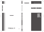
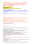
2.3 Names of Parts
• Operation Side (Right side as viewed from the propeller.) Contains the main parts necessary for operation
Oil cooler(engine)
Dipstick(engine)
Fuel oil filter
Engine name plate
Trawling lever
(Option)
Dipstick(Marine gear) Lube oil filter
Fresh wate pump
Fuel injection pump
• Non-Operation Side
Alternator
Fresh wate cooler
Filler cap
(Fresh water)
Turbocharger
*Inter cooler
V-belt
Clutch lever
Seawater pump
Starter motor
Oil cooler(Marine gear)
NOTE:
The 4JH3-DTE engine with KMH4A is used as the example for the above drawings.
The 4JH3-TE is not equipped with an intercooler (indicated by * mark in the above).
2. PRODUCT EXPLANATION
11
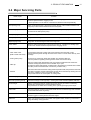
2.4 Major Servicing Parts
Name of part
Function
Fuel filter
Removes dust and water from fuel. The filter is a cartridge type, and the inner element
should be replaced before clogging occurs.
A water separator is on the bottom of the filter and should be drained periodically.
Fuel priming pump
This is a manual fuel pump. Moving the knob on the top of the fuel filter feeds the fuel.
The pump is also used to bleed air from the fuel system.
Fuel feed pump
This is a mechanical pump used to feed fuel to the fuel injection pump.
It is built into the fuel injection pump.
Filler port (engine oil)
Filler port for engine lube oil.
Filler port (marine gear oil)
Filler port for marine gear lube oil. Located on the top of the marine gear case.
Dipstick (engine oil)
Gauge stick for determining the level of the engine oil.
Lube oil filter
Filters fine metal fragments and carbon from the lube oil. The filter is a cartridge type,
and the inner element should be replaced before clogging occurs.
[ Cooling Water System ]
This engine is cooled by 2 cooling systems:fresh water and seawater.
・ Fresh water cooler
(Built-in fresh water tank)
The tank stores the fresh cooling water and is built into the fresh water cooler.
Cooling seawater passes through the fresh water cooler to cool the fresh water by heat
exchange.
・ Cooling water pump
Located on top of the fresh water tank the filler cap closes the filler port.
It has two pressure regulating valves (pressure valve and vacume valve).
・ Filler cap
When the cooling water temperature rises, the pressure inside the fresh water tank
increases causing the pressure valve in the filler cap to open.
Hot water and steam pass through a rubber hose to the subtank to condense the hot water.
(The filler port and the subtank are connected by a rubber hose.)
・ Subtank
When the load is reduced and the cooling water temperature falls, the pressure in the fresh
water tank is lowered, and this activates the vacume valve in the filler cap causing the cool
water in the subtank to return to the fresh water tank.
This process reduces the consumption of cooling water.
Oil cooler (engine oil)
This heat exchanger cools the engine oil with seawater.
Oil cooler (marine gear oil)
This heat exchanger cools high temp. marine gear oil with seawater.(KBW21,KMH4A)
Turbocharger
With the pressurized intake air feeding device the exhaust gas turbine is rotated by
exhaust gas, and the power is used to rotate the blower
This pressurizes the intake air for sending to the cylinder gives high power output.
Intercooler
This heat exchanger cools the pressurized intake air from the turbocharger with seawater
and increases the intake air guantity.
Starter motor
This is a DC motor for electrical starting. Electric current causes the pinion gear to engage
with the ring gear on the flywheel to start the engine.
Alternator
This is a AC generator built in the rectifier and regulator which rotates by V-belt drive to
charge the battery during operation.
12
2. PRODUCT EXPLANATION
2.5 Operation Equipment
Explanation of the equipment used to operate the engine.
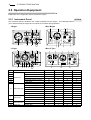
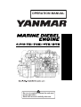
2.5.1 Instrument Panel
OPTION
The instrument panel is located in the cockpit, separate from the engine. The following instruments enable
you to start and stop the engine and to monitor its condition during operation.
♦B type
♦New B type
♦C type
♦New C Type
No.
Model
Key switch (Starter switch)
Engine stop switch
7
8
10
9
Switch unit
Alarm buzzer
Alarm buzzer stop switch
Illumination switch for meters
Lamp check
11
11
Battery not charging
C.W high temp.
6
Alarm lamp unit
L.O. low press.(engine)
Fuel filter
Sail drive leak
Fuel empty
1
2
4
3
12
Tachometer
Sub meter unit
Clock unit
Tachometer with hour meter
Tachometer
Hour meter
C.W. temp. meter
L.O. press. meter
Quartz clock
B
C
New B
New C
O
O
O
×
O
O
O
O
O
×
×
×
×
O
×
×
×
×
O
O
O
O
O
×
O
O
O
×
×
×
×
O
O
O
O
×
O
O
O
O
O
×
O
O
O
×
∆
O
O
O
O
O
O
O
×
O
O
O
O
O
∆
O
-
-
-
-
×
×
∆
O
O
∆
O: Available
×: Not available
∆: Optional
2. PRODUCT EXPLANATION
13
(1) Meters
The following meters are located in the upper center part of the instrument panel.
♦B/C and New B/C type panels use analog electric systems and have a pointer indicator.
Turn the panel light switch (illumination switch) ON for easy viewing.
• Tachometer
The engine speed is indicated. Engine speed can be monitored.
• Hour meter
The number of hours of operation is indicated, and can be used as a guide for periodic maintenance checks.
• Cooling Water Temperature Meter (C, New C)
The cooling water temperature is indicated. Enables monitoring of the cooling condition of the engine.
• Lube Oil Pressure Meter (C, New C)
The engine oil pressure is indicated.
Enables monitoring of the condition of the engine’s lube oil.
(2) Alarm Devices
When there is some problem during operation, the alarm buzzers and lamps will come on.
• Alarm buzzers
When the various alarm lamps come on, the alarm buzzers will come on at the same time and continue to
sound. However, no alarm buzzer will sound when the charge lamp comes on.
• Buzzer stop switch
When the buzzer sound is no longer necessary, it can be turned off with the Buzzer stop switch.
• Alarm lamps
The alarm monitor window indicates the trouble spot when one of the symbols shown below lights up.
When operation is normal the alarm lights are off; however, should some problem arise, the sensors will pick
it up and cause the light behind the appropriate symbol to come on.
1. BATTERY CHARGE
When the charge is abnormal, the lamp will come on. When charging begins the lamp will
go off. (Alarm buzzer will not sound when the lamp comes on.)
2. C.WATER TEMP
When the temperature of the cooling fresh water exceeds the maximum (95 degree C or
higher), the lamp will light. Continuing operation at temperatures exceeding the maximum
will result in damage and seizure. Check the load and the cooling system for any abnormalities.
3. LUB.OIL PRESS.
When the lube oil pressure falls below specified oil pressure sensor will detect this and the
lamp will come on. Continuing operation with insufficient oil will result in damage and seizure. Check the oil level.
4. FUEL FILTER (New C)
When the drain inside the water separator in the fuel filter becomes excessive, the sensor
will cause the lamp to come on. Clean out the drain in the water separator. If operation is
continued without cleaning, it will become impossible to feed fuel to the engine or damage
and seizure of the fuel injection pump will result.
5. SAIL DRIVE LEAK (New C, New B(optional))
When the seal rubber attached between sail-drive and hull is damaged and sea water leaks
into between the seal rubbers, the lamp comes on. If this hapenes, stop the engine and
quickly return to the nearest port under sail for repairs.
6. FUEL EMPTY (New B, New C(optional))
When the amount of fuel in the tank is insufficient, the sensor will activate the lamp. Fill with
fuel.
14
2. PRODUCT EXPLANATION
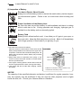
(3) Starter Switch
This is the switch for starting engine operation. It is a rotary-type 3-step switch. Position is changed by turning the key in the switch.
OFF
ON
is the position where the engine is
stopped. All current is cut off.
The key can be inserted and removed in this
position.
Stop position
Drive position
is the position for operation.
Current flows to the instruments and alarm
devices.
START is the position for starting.
When the starter motor turns, the engine
starts.
The key returns automatically to the ON position when you remove your hand.
Starting position
Starter switch
GLOW is the position for turning on the air heater. The air heater (OPTION) aids starting during cold conditions by warming up the intake air before starting.
Note:Neutral Safety Switch
OPTION for KM4A KMH4A
The engine can only be started when the clutch is in Neutral. If an attempt is made to start the engine in
any other position, the neutral safety switch will operate to make starting impossible.
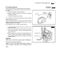
(4) Stop button
The engine is stopped by pushing the stop button on the
right of the control panel.
When the stop button is pushed, the solenoid valve on
the fuel injection pump works to cut off the fuel supply
and stop the engine.
Continue to push the stop button until the engine has
come to a complete stop.
Stop button
STOP
GLOW
OFF
ON
START
2. PRODUCT EXPLANATION
15
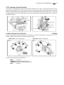
2.5.2 Remote Control Handle
This engine is controlled by the remote control handle located in the cockpit. The speed control lever on the
engine side and clutch lever on the marine drive are connected by remote control cable with the various
remote control handles in the cockpit (We reccomend you a single hanrdle remote control device). There are
the following kinds of remote control handles. When using other kinds of remote control devices, consult their
operation manuals.
Speed lever
Trawling lever
High speed
Low speed
Trawling
Ahead
High speed
Clutch lever
Astem
Neutral
(1) Morse Remote Control Handle
OPTION
This is a single-handle remote control device connected by a remote control cable. It operates the clutch to
neutral, forward, and reverse and controls the engine speed.
Model MT-3 : Top mounting type.
MV
FW
D
L
TRA
NEU
RE
V
W
LO ED
E
SP
HIGH D
E
SPE
V
RE
FW
D
LOW
SPEE
D
NEUTRAL
H
HIGEED
P
W S
LO EED
SP
HI
SPEGH
ED LO
SP W
EE
D
MT-3
Model MV : Side mounting type.
H
SP IGH
EE
D
The labels for operation on the handle are:
∆FWD:
Forward
NEUTRAL: Clutch disengaged position
THROTTLE:Position to reduce engine speed
∇REV:
Reverse
16
2. PRODUCT EXPLANATION
Operation of the handle is as follows:
• Starting and stopping
Put the handle in NEUTRAL.
This puts the clutch in the cut-off position (stop) and idles the engine at a low speed.
• Forward
Move the handle from NEUTRAL to ∆FWD(forward).
This engages the clutch in forward and simultaneously increases the engine speed.
Pushing the handle further in the same direction increases engine speed to full speed.
• Reverse
Move the handle from NEUTRAL to ∇REV(reverse).
This engages the clutch in reverse and simultaneously increases the engine speed.
Pushing the handle further in the same direction increases engine speed to full speed.
• Free throttle operation
When the boat is stopped (clutch is in neutral position), the idling speed of the engine can be increased in
the following manner.
1. Leave the handle lever in NEUTRAL.
MT-3
2. Disengage the clutch.
NEUTRAL L
O
WS
PEE
D
MT-3:Pull out the handle lever all the way.
D
PEE
HS
HIG
MV: Pull out the free throttle button next to the
handle lever.
3. With the lever or button pulled out, move the handle
lever in either the forward or reverse direction to
increase idling speed.
Pull out handle lever
MT-3:Return the handle lever to NEUTRAL. The
lever will return auto matically to the normal
position.
MV: Return the handle lever to NEUTRAL and
push the free throttle button in.
MV
NEUTRAL
D LOW SPE
SPEE
ED
H
G
I
H
• Returning to normal operation from free throttle operation.
Pull out free throttle button.
Free throuttle button
2. PRODUCT EXPLANATION
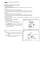
(2) Trawling Handle
The trawling control is a single remote control handle.
The marine gear trawling lever operates by remote control cable.
The operation labels on the handle are:
H:Highest trawling speed and normal (not trawling)
operation position.
L: Lowest trawling speed position.
OPTION KMH4A
Normal
operation
NOTICE:
•Make sure to be the engine speed 1000rpm or
less when trawling operation.
•Make sure to be trawling handle position H
when normal operation (not trawling operation).
Tighten
Trawling
Loosen
Only operate with the trawling handle at the low engine
speed, 1000 rpm or less.
While trawling operation, the marine gear clutch is at half
clutching running and the propeller speed is very slow
slipping against the clutch disk.
Do not operate at over 1000rpm engine speed.
1. Loosen the handle grip by turning it to the left. This
frees the handle.
2. Move the handle toward L(low speed) and position
at the desired speed. Turn the handle grip to the
right to secure it.
3. Before returning to normal high speed operation, be
sure to position the handle in H(high speed) tightening the grip by turning it to the right to secure the
handle in place.
17
KMH4A
Trawling lever
High speed
Low speed
(trawling)
18
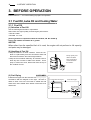
3. BEFORE OPERATION
3. BEFORE OPERATION
Perform items 3.1 – 3.7 before starting to prepare for operation.
3.1 Fuel Oil, Lube Oil and Cooling Water
3.1.1 Fuel Oil
(1) Selection of Fuel Oil
Use the following diesel fuels or equivalents.
Select fuels of a higher quality for best engine performance.
• ISO 8217 DMA
• BS 2869 A1 or A2
[Fuels eguivalent to Japanese Industrial standard, JIS. No. K2204-2]
Cetane fuel number should be 45 or greater.
NOTICE:
When other than the specified fuel oil is used, the engine will not perform to full capacity
and parts may be damaged.
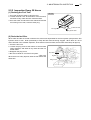
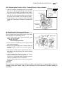
(2) Handling of Fuel Oil
• Keep the fuel oil in a clean container. Store the container in a place away from rain and dirt as water and
dust mixed in with the fuel cause engine failure.
• Keep the fuel container stationery for several hours to
allow any dirt or water to settle to the bottom. Use a
pump to extract the clear, filtered fuel from the top of
the container for use.
CUSTOMER
Install the fuel pipe from the fuel tank to the fuel pump in
accordance with the diagram to the right. Be sure to
attach a drain cock to the fuel tank to enable dirt and
water which have settled at the bottom of the tank to be
drained off.
To fuel injection pump
(3) Fuel Piping
Pump up only fuel
above the down
haif, leaving dreg
accumulated on
the bottom.
Fuel oil filter with engine
Fuel return pipe
Fuel oil tank
Less than 500mm
Fuel oil cock
Drain cock
3. BEFORE OPERATION
19
3.1.2 Lube oil
(1) Selection of Engine Lube Oil
Use the following lube oil:
*API Classification CD
(Standards of America Petroleum Institute)
*SAE Viscosity
15W40
(Standards of Society of Automotive Engineering)
NOTICE:
Using other than the specified lube oil will lead to seizure of parts inside the engine and
gear device , abnormal wear, and shorten engine life. It will also effect the starting ability
and power output.
(2) Marine Gear Oil and sail-drive oil
Be sure to use the following lube oil for the marine gear and the sailing boat drive.
• KBW21
Converter oil for automobiles ATF
• KM4A, KMH4A
API Classification .............. CC or higher
SAE Viscosity.................... #20 or #30(not available multi grade)
• SD40-4T
Refer to the operation manual for the sail drive.
(3) Handling the Lube Oil
• When handling and storing lube oil, be careful not to allow dust and water to enter the lube oil.
Clean around the filler port before refilling.
• Do not mix lube oils of different types or brands.
Mixing may reduce the lubricating performance. Different oils are used for the engine and the marine
gear.
Be careful to use the correct oil for each one and store in separate clearly labeled containers.
3.1.3 Cooling Water
NOTICE:
Be sure to add LLC to cooling fresh water.
In cold seasons, the LLC is especially important.
Without LLC, cooling performance will decrease due to scale and rust in the cooling water
line. Without LLC, cooling water will freeze and expand, breaking various parts.
1) Choose LLC which will not have any adverse effects on the materials (cast iron, aluminum, copper, etc.) of
the engine’s fresh water cooling system.
2) Strictly use the proper mixing ratio of LLC to fresh water as instructed by the LLC maker. If incorrect ratio of
LLC to fresh water is used, the cooling performance of the cooling water will drop and the engine may
become overheated.
3) Do not mix different types (brand) of LLC, chemical reactions may make the LLC useless and engine trouble could result.
NOTICE:
Excessive use of LLC also lowers the cooling efficiency of the engine.
Be sure to use the mixing ratios specified by the LLC maker for your temperature range.
20
3. BEFORE OPERATION
3.2 Supplying Fuel
Fires from Oil Ignition
• Be sure to use the correct type of fuel when refueling.
Mistakenly filling with gasoline or the like will result in ignition.
• Be sure to stop the engine before refueling.
If you spill fuel, wipe such spillage carefully.
• Never place oils or other flammable material close to the engine as this
could result in ignition.
3.2.1 Filling the Fuel Tank
Fill the tank with clean fuel which has not been contaminated with water or dust.
Fill the tank to approximately 90% of its capacity, and take care not to let the fuel spill over during operation.
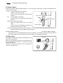
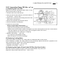
3.2.2 Bleeding the Fuel System
Bleed the fuel system according to the following procedure. When there is air in the fuel system, the fuel
injection pump will not be able to function.
Priming pump
Air bleeding bolt
jec
l in
fue
To
tion
pum
p
1. Check the amount of fuel in the fuel tank. If insufficient, replenish.
2. Open the fuel cock of the fuel tank.
3. Loosen the air bleeding bolt on the top of the fuel filter
by turning it 2∼3 times with a minus driver.
4. Feed the fuel with the priming pump.
The priming pump is on the top of the fuel filter.
Move the priming pump knob up and down until fuel
mixed with air bubbles flows out of the air bleeding
bolt.
5. When the fuel coming out is clear and not mixed with
any bubbles, tighten the air bleeding bolt.
Fr
om
fu
el
ta
nk
3. BEFORE OPERATION
21
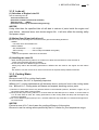
3.3 Supplying Engine Lube Oil
Fill with the specified amount of engine oil.
1. Remove the oil inlet cap on the top of the bonnet and
fill with oil.
2. Remove the oil dipstick and check the level of the oil
with the gauge on the stick.
Oil should be filled to the upper mark on the dipstick
gauge.
Engine oil capacity:
See 2.2 Engine Specifications.
Oil Inlet
Cap
Dipstic
Bonnet
Dipstic
Guide
Oil Inlet
3. Replace the dipstick and tighten the oil inlet cap firmly
by hand.
NOTICE:
Do not overfill.
Overfilling will cause oil to be sprayed out from
the breather during operation and lead to
engine problems.
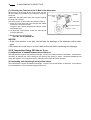
3.4 Supplying Marine Gear Lube Oil
Fill with the specified amount of marine gear oil.
1. Remove the oil inlet cap with dipstick on the top of the
marine gear and fill with marine gear oil.
2. Fill with oil to the upper mark on the dipstick attached
to the cap.
To measure the oil level, wipe the dipstick using a
cloth, and then measure the oil level by inserting the
dipstick without tightening screw of the oil inlet cap.
Fill with the necessary amount of oil.
Marine gear oil capacity:
See 2.2 Engine Specificati.ons.
3. Replace the cap and tighten.
NOTICE:
Lower limit is indicated at the end face of the
dipstick.
NOTICE:
Do not overfill.
Overfilling will cause oil to be sprayed out during operation and effect the efficiency of the
marine gear.
Dipstik
Upper Limit
Lower Limit
Upper
Limit
Lower
Limit
22
3. BEFORE OPERATION
3.5 Supplying Cooling Water
Burns from Scalding
• Never remove the filler cap of the fresh water cooler while the engine is still
hot.
Steam and hot water will spurt out and seriously bum you. Wait until the
water temperature has dropped, then wrap a cloth around the cap and
loosen it slowly.
• After inspection, refasten the cap firmly. If the cap is not secure, steam or
scalding water may be emitted during operation causing bums.
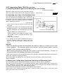
Fill the fresh water tank and the subtank with fresh cooling water.
1. Before filling, check to be sure the drain cocks (indicated in the diagram) are closed.
4JH3-TE /TCE
Turbocharger
Exhaust manifold
Fresh water cooler
Fresh water
pump
Turbocharger
(Fresh water)
(Fresh water)
(Fresh water)
Lube oil
filter
(Fresh water)
(Seawater)
Inter cooler
(Fresh water)
(Seawater)
(Fresh water)
(Seawater)
Oil cooler (marine
gear)
KMH4A
2. Remove the filler cap of the fresh water tank by turning the cap counterclockwise 1/3 of a turn.
3. Pour cooling water slowly into the fresh water tank so
that air bubbles do not develop. Supply until the water
overflows from the filler port.
Fresh water tank capacity:
See 2.2 Engine Specification
Filler cap
Notches
Slots
Fresh water cooler
4. After supplying cooling water, replace filler cap and
tighten it firmly. To replace the cap, align the notches
on the back of the cap with the slots on the filler port
and turn clockwise 1/3 of a turn.
(Cont. on next page.)
5. Remove the subtank cap and fill with water to the
upper limit, FULL. Replace cap.
Subtank capacity:0.8l
6. Check the rubber hose connecting the subtank to the
fresh water cooler. Be sure the hose is securely connected and there is no looseness or damage. If the
hose is not watertight, an excessive amount of cooling
water will be consumed.
Filler cap
To fresh water tank
Upper limit
Lower limit
3. BEFORE OPERATION
23
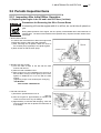
3.6 Cranking
When the engine is being used for the first time or if it has not been used for a long period of time, perform
cranking before starting to distribute oil to all of the parts. Using an engine which has been stored for a long
period of time without the cranking procedure may result in engine seizure, since there will no longer be oil on
the moving parts after storage.
1. Open Kingston cock.
2. Cut off all clutches and the main switch, making sure
that all auxiliary machines are in a no-load position.
NEUTRAL
NEUTRAL
3. Put marine gear in NEUTRAL
4. Crank the engine.
Push the stop button to stop fuel injection while crawling.
1) Put the key into the starter switch.
2) While pushing the stop button, turn the key to the
START position and hold it there. The engine will
begin turning. If you remove your hand from the
stop button, the engine will start. Do not take your
hand off the button.
MT-3
MV
Stop button
5. Continue cranking the engine for about 5 seconds,
checking for abnormal sounds.
6. Return the key to the OFF position. The engine will
stop.
STOP
Drive position
OFF
GLOW
ON
START
Start position
Starter switch
3.7 Checking the Lube Oil and Cooling Water
When engine lube oil, marine gear lube oil, and cooling water are put in for the first time, or after they have
been replaced, their levels should be checked after a trial operation. Oil and water will be distributed to the
various parts during the operation, lowering the levels of oil and water. Replenish to the proper amounts.
• Supplying engine lube oil
• Supplying clutch lube oil
• Supplying cooling water
→ See 3.3
→ See 3.4
→ See 3.5
24
4. HOW TO OPERATE
4. HOW TO OPERATE
Alcohol
• Never operate the engine while you are under the influence of alcohol or
when you are ill or feel unwell as this results in accidents.
Exhaust Gas Poisoning
• Be sure to establish good ventilation in the engine room with windows,
vents, or other ventilation equipment. Check again during operation to be
sure that ventilation is good. Exhaust gas contains poisonous carbon monoxide and should not be inhaled.
Moving Parts
• Do not touch the moving parts of the engine (propeller shaft, V-belt, PTOpulley, etc.) during operation or let your clothing get caught in them as this
can result in injury.
• Never operate the engine without the covers on the moving parts.
• Check before starting the engine to see that any tools or cloths used in
maintenance have been removed from the area.
Bums from Contact with Hot Engine Parts
• The whole engine is hot during operation and immediately after stopping.
The turbocharger, exhaust manifold, exhaust pipe, and engine are very hot.
Never touch these parts with your body or clothing.
4.1 Inspection Before Starting
Be sure to check the following items daily before starting the engine.
(1) Visual Check
Check for the following:
If any problem is found, do not use the engine until repairs have been completed.
• Oil leakage from the lube oil system
• water leakage from the cooling water system
• Damage to parts
• Fuel oil leakage from the fuel system
• Loosening or loss of bolts
(2) Checking and Resupplying Fuel Oil
Check the fuel level inside the fuel tank and supply with the recommended fuel if necessary.
→See 3.2
(3) Checking and Resupplying Engine Lube Oil
1. Check the engine oil level with the oil dipstick.
2. If the oil level is low, supply with the recommended lube oil using the filler port.
Supply oil up to the upper mark on the oil dipstick.
→See 3.3
4. HOW TO OPERATE
25
(4) Checking and Resupplying Marine Gear Oil
1. Check the marine gear oil level with the dipstick.
2. Supply with the recommended oil if necessary.
Check the oil level with the dipstick while filling to the upper mark.
→See 3.4
(5) Checking and Resupplying Cooling Water
Burns from Scalding
• Never remove the filler cap of the fresh water tank while the engine is still
hot.
Steam and hot water will spurt out and seriously burn you. Wait until the
water temperature has dropped, then wrap a cloth around the cap and
loosen it slowly.
• After inspection, refasten the filler cap firmly. If the cap is not secure, steam
or scalding water may be emitted during operation causing bums.
1. Check the cooling water level in the subtank.
If the water level is close to the lower limit, remove the subtank cap and fill with fresh water to the upper
limit.
2. When the water level in the subtank is low, remove the filler cap for the fresh water tank and check the
amount of cooling water in the fresh water tank. Fill with fresh water the fresh water tank if the level is low.
→See 3.5
• Check the fresh water level before operation while the engine is cold.
Checking the water level while the engine is hot is dangerous, and the cooling water reading will be misleading due to thermal expansion.
• Check the cooling water daily at the subtank and supply if necessary.
Do not remove the fresh water tank filler cap regularly.
• The amount of water in the subtank will increase during operation. This is normal.
When the engine is stopped, the temperature of the cooling water will drop causing the extra water in the
subtank to return to the fresh water tank.
NOTICE:
If the cooling water runs out too often, or if the water level in the fresh water tank falls without any change in the subtank water level, there may be some leakage of water or air. In
such cases, consult your Yanmar dealer or distributor without delay.
(6) Checking the Remote Control Handle
Be sure to check that the remote control handle lever moves smoothly before use. If it is
hard to operate, lubricate the joints of the remote control cable and also the lever bearings.
If the lever comes out or there is play in the lever, adjust the remote control cable.
→See 5.2.3(5)
(7) Preparing Reserves of Fuel, Lube Oil, and Cooling Water
Have sufficient fuel ready for the day’s operation. In addition, have a reserve of fuel, lube
oil, and cooling water (sufficient for at least one refill).
26
4. HOW TO OPERATE
4.2 Checking the Illumination Lamps
of the Panel Meters
Be sure to check the alarm devices and other instruments on the panel before and after starting the engine. If
the devices are not working properly, it is impossible to prevent any problems arising from insufficient oil and
water in the engine. Make checking the alarm and other devices before and after starting a regular practice.
If having the optional instrument panel B or C or NewB or NewC, Refer to 2.5.1(2).
4.2.1 Checking the Illumination Lamps of the Panel Meters
Turn on the illumination lamp switch of the instrument panel after battery switch and starter key switch turned
on and check to see that the illumination lamps come on.
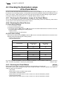
4.2.2 Checking the Alarm Devices
(1) Check before starting.
1. Turn on the battery switch.
2. Put the key in the starter switch.
3. Turn the key from the OFF position to ON, and check to see that the alarm devices as shown in the diagram below [Before Starting] are working properly.
• Buzzer sounds.
• Charge and engine oil press light up.
(2) Check after starting.
When the key returns from the START position to ON, check to see that the alarm devices as shown in the
diagram below [After Starting] are working properly.
• Buzzer stops sounding.
• All of the lamps go off.
Function of Alarm Devices
Before Starting
OFF→ON
After Starting
START→ON
On
Off
Charge Lamp
On
Off
Cooling Water Temperature
Off
Off
engine Oil pressure
On
Off
Fuel filter
Off
Off
Sail drive leak
Off
Off
Key Operation
Alarm Buzzer
Alarm Lamps
By performing these procedures, it can be determined whether or not the electric circuit is in good working
order. If there is any problem, consult your yanmar dealer.
→See 2.5.1(2)
4.2.3 Checking the Panel Meters
OPTION
Before starting, the pointer on the meter should be in a fixed position on the left side.
The pointer on the meters will begin moving once the engine is started. Check the position of the pointer to
make sure there are no problems.
• Tachometer
Meter pointer moves to indicate engine speed.
• Cooling Water Temperature Meter
Meter pointer in the white area is normal. Pointer in the red area indicates a problem.
• Lube Oil pressure Meter
Meter pointer in the white area is normal. Pointer in the red area indicates a problem.
4. HOW TO OPERATE
27
4.3 starting
4.3.1 Daily Starting
Follow the following procedures for starting under normal conditions.
1. Open the Kingston cock. (option)
2. Open the fuel tank cock. (option)
3. Cut off all clutches and main switches for all auxiliary
machinery so that there is no load.
4. Put the remote control handle in NEUTRAL.
5. Set the governor handle in the low speed position
(when there is an independent governor remote control handle).
6. Turn on the battery switch. (option)
7. Insert the key into the starter switch and turn it to ON,
the buzzer sounds and the alarm device lamps come
on, indicating that the alarm equipment is working
properly.
8. Turn the key to START to start the engine. When the
engine has started, remove your hand from the key.
The key will automatically return to the ON position.
Check to see that alarm lamps have gone off and the
buzzer has stopped.
→See 4.2.2
NEUTRAL
NEUTRAL
MT-3
MV
Remove hand after engine starts
STOP
Drive position
OFF
GLOW
ON
START
Start position
Starter switch
4.3.2 Starting Under Low Temperature Conditions
When starting the engine under difficult low temperature conditions (approximately 0 degree C or lower), use
the air heater to enable easier starting. Follow steps 1.∼6. of the above procedure, and then follow the steps
below.
OPTION
7. Turn the key from the OFF position to GLOW. Continue to hold the key in the GLOW position to heat up the
air heater.
8. Turn the key to START and start the engine. After the engine starts, remove your hand from the key.
NOTICE:
Do not leave the air heater on for longer than 20 seconds at a time. Leaving the air heater
on for longer periods of time will result in damage.
4.3.3 Restarting After Starting Failure
When attempting to start the engine after starting failure, be sure that the engine is at a complete stop before
turning the starter switch key. If the engine is restarted while the engine still has not stopped, the pinion gear
of the starter motor will be damaged.
• When the engine will not start after several attempts, check the fuel system. If there is air in the fuel system,
the fuel will not be fed and starting will not be possible.
After bleeding air from the system, attempt to restart the engine.
→See 3.2.2
NOTICE:
Do not hold the starter switch on for more than 15 seconds at a time. If the engine does not
start the first time, wait for about 15 seconds before trying again.
28
4. HOW TO OPERATE
4.3.4 After the Engine has Started
(1) Warming-up running
After the engine has started, let it run for about 5 minutes. This warms up the engine and distributes oil to all
of the parts.
NOTICE:
The engine will seize if it is operated when cooling seawater discharge is too small or if load
is applied without any warming up operation.
MT-3
L
SP OW
EE
D
Pull out handle lever
MV
W
LO ED
E
SP
NEUTRAL
Free throttle button
H
HIG D
E
SPE
NEUTRAL
GH
HI ED
E
SP
♦Morse Remote Control Handle (If having the optional)
1. Leave the remote control handle in NEUTRAL.
2. Pull out the handle lever (MT-3) or the free throttle
button (MV) and adjust the speed to no more than
1500 rpm and run the engine at low speed with no
load.
→See 2.5.2(4)
Pull out free throttle button.
(2) Checking for problems
While warming up the engine, check the following items.
1. Check that the meters and alarm devices on the instrument panel are normal.
2. Check for water, fuel and oil leakage from the engine and marine gear.
3. Check that exhaust color, engine vibrations and sound are normal.
4. Check that sufficient cooling water is discharged from the seawater outlet pipe.
Operation with too little seawater discharge will burn the impeller of the seawater pump.
If seawater discharge is too small, stop the engine immediately, identify the cause and repair
• Is the Kingston cock open?
• Is the inlet of the Kingston cock clogged?
• Is the seawater suction hose broken, or does the hose suck in air due to a loose joint?
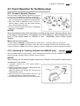
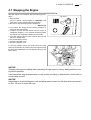
4.4 Adjusting the Engine Speed
Adjust the speed of the engine by moving the remote control handle slowly and smoothly.
Move the handle forward and adjust the speed between L(low speed) and H(high speed).
♦For the Morse remote control handle, adjust the engine speed between NEUTRAL and ∆FWD or NEUTRAL
and ∇REV.
NOTICE:
For a new engine be especially careful not to change speeds abruptly or attach a heavy
load for the first 50 hours of operation. Doing so will result in damage and shorten the life of
the engine.
4. HOW TO OPERATE
29
4.5 Clutch Operation for the Marine Gear
FW
D
L
TRA
NEU
RE
V
LOW
HIGH D SPEED
E
SPE
W
LO ED
E
SP
HI
SPE GH
ED
L
V NEUTRA FWD
RE
H
HIG ED
E
W SP
LO EED
SP
H
SP IGH
EE
D
Use the remote control handle to operate the clutch for
the marine gear (FORWARD, NEUTRAL, REVERSE).
• Be sure to run the engine at the lowest possible speed
when changing between FORWARD and REVERSE.
• Return the handle to NEUTRAL before moving it to
another position. Always move the handle smoothly;
never change positions abruptly.
• Be sure to securely position the handle in FORWARD,
NEUTRAL, or REVERSE.
SP LOW
EE
D
4.5.1 Forward, Neutral, Reverse
MV
MT-3
NOTICE:
Never operate the clutch when the engine is running at high speed. Doing so will put stress
on the engine, driving device, and propeller and result in damage. When shifting the clutch
lever, put the engine speed on 1000rpm or less. Additionally, never change speeds
abruptly.
♦Morse Remote Control Handle
• Put the handle in NEUTRAL (middle position) to stop the boat. The engine will idle at low speed.
• Move the handle to ∆FWD to go forward. When the clutch is engaged in forward, the speed will increase.
• Move the handle to ∇REV to go in reverse. When the clutch is engaged in reverse, the speed will increase.
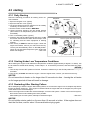
4.5.2 Switching to Trawling (Available for KMH4A only)
OPTION KMH4A
Use the trawling handle to begin trawling. When changing from forward or reverse operation to trawling, the
speed of propeller revolution will be reduced to a bare minimum.
NOTICE:
When trawling, do not raise the engine speed over 1000rpm, as this results in early wear of
and damage to the clutch.
1. Operation continues at a low engine speed of
1000rpm or less.
2. Reduce the speed by moving the trawling handle from
H(high speed) to L(low speed).
Adjust the speed to the desired rate and secure the
trawling handle in place.
3. Before returning to normal operation, be sure to put
the trawling handle on H(high speed) position.
4. Increase engine speed and continue normal operation.
Trawling
Normal
operation
Trawling
Loosen
30
4. HOW TO OPERATE
4.6 Check During Operation
Always be on the lookout for problems during engine operation.
Pay particular attention to the following.
(1) Is sufficient water being discharged from the seawater outlet pipe?
If the discharge is small, stop the engine immediately, identify the cause and repair.
(2) Is the exhaust color normal?
The continuous emission of black exhaust shows engine overloading.
This shortens the engine’s life and should be avoided.
(3) Are there abnormal vibrations or noise?
Do not operate at speeds which produce violent vibrations.
Depending on the hull structure, engine and hull resonance may suddenly become great at a certain
engine speed range, causing heavy vibrations. Avoid operation in this speed range.
If you hear any abnormal sounds, stop the engine and inspect.
(4) Alarm buzzer sounds during operation.
If the alarm buzzer sounds during operation, lower the engine speed immediately, check the alarm lamps,
and stop the engine for repairs.
(5) Is there water, oil, or gas leakage, or are there any loose bolts?
Check the engine room periodically for any problems.
(6) Is there sufficient oil in the fuel tank?
Replenish fuel oil in advance to avoid running out of fuel during operation.
(7) When operating the engine at low speed for long periods of time, race the engine once every 2
hours.
Racing the Engine
L
SP OW
EE
D
W
LO ED
E
SP
NEUTRAL
Free throttle button
H
HIG D
E
SPE
Racing the engine removes carbon built up in the combustion chamber and around the fuel injection valve.
Neglecting to race the engine will cause the exhaust to
turn black and lower the efficiency of the engine.
NEUTRAL
GH
HI ED
E
SP
♦Morse Remote Control Handle
Pull out the handle lever (MT-3) or the free throttle button (MV) and shift the engine speed from high t to low
several times.
→See 4.3.4(1)
Pull out handle lever
Pull out free throttle button
MT-3
MV
NOTICE:
Never turn off the battery switch or spark the
battery cable during operation. Damage to
parts in the electric system will result.
ON
Battery Switch
OPTION
OFF
4. HOW TO OPERATE
31
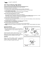
4.7 Stopping the Engine
Stop the engine in accordance with the following procedures.
1. Stop the boat.
Put the remote control handle in NEUTRAL and
reduce the engine speed to the lowest speed.
2. Be sure to race the engine before stopping it.
→See 4.6(7)
3. Cool down the engine at low speed (1500rpm or
lower) for about 5 minutes.
4. Continue to push the stop button until the engine is
completely stopped. If you release the button before
the engine has completely stopped, it may restart.
5. Turn the starter switch to OFF, remove the key and
place it in a safe place.
6. Cut off the battery switch.
7. Close the fuel tank cock.
8. Close the kingston cock.
Stop button
STOP
GLOW
OFF
ON
START
In the rare instance where the engine does not stop
when the stop button is pushed, stop the engine moving
the stop lever attached on the fuel injection pump to the
left by hand.
Stop
Stop lever
NOTICE:
Stopping the engine suddenly after operating at high speed or heavy loading without cooling down operation.
It will cause the engine temperature to rise quickly resulting in deterioration of the lube oil
and sticking of parts.
NOTICE:
Neglecting to close the Kingston cock will allow water to leak into the boat and may cause it
to sink. Be sure to close the cock.
32
4. HOW TO OPERATE
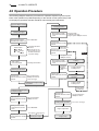
4.8 Operation Procedure
The following diagram shows the procedures for operation explained up to this point.
Parts of the operation may differ depending on the remote control system being used.
Accompanying operation manuals should be read carefully and understood.
Inspection Before Starting
Starting Operation
Starting the Engine
Driving Device Clutch
Clutch Remote Control Lever
Driving Device Clutch
Clutch Remote Control
Lever
Put in NEUTRAL
Checking the Alarm
Devices
Turn the key for no
longer than 15 secs.
Remove hand from
key after starting.
Starter Switch
OFF
ON
ON
START
ON
Engage Clutch
Forward or Reverse
Engine speed 1000rpm or lower
Speed Lever
Govenor Remote Control
Handle
Adjust Speed
Speed Lever
Govenor Remote Control
Handle
KMH4A
Low Speed Position
1000rpm or lower
Alam Lamps
Instrument Panel
Checking for Problems
Driving Device Clutch
Clutch Remote Control
Lever
Forward or
Reverse
1000rpm or
lower
Warming-up Operation
Trawling
Trawling Handle
Trawling Lever
Adjust Speed
Speed Lever
Govenor Remote Control
Handle
Low Speed Position
1500rpm or lower for
5 mins. or longer
Speed Lever
Govenor Remote Control
Handle
Adjust Speed
Checking the Engine During
Operationl
Trawling Handle
Trawling Lever
High Speed
Position(H)
Stopping the Boat/Preparing
to Stop the Engine
Speed Lever
Govenor Remote Control
Handle
Driving Device Clutch
Clutch Remote Control
Lever
Speed Lever
Govenor Remote Control
Handle
Low Speed Position
1000rpm or lower
Cooling-down Operation
For 5 mins. or longer
Low Speed Position
1000rpm or lower
Put in NEUTRAL
Engine Stop Button
Low Speed
Speed Lever
Govenor Remote Control
Handle
Return to Normal
Operation
High Speed
Racing the engine
Repeat Several Times
Engine Stops
4. HOW TO OPERATE
33
4.9 Long-Term Storage
4.9.1 Before storing for long periods of time, perform the following.
(1) Periodic Inspection
If the time for a periodic inspection is close, perform it before storing the engine for a long period of time.
(2) Draining the Cooling Water
When not using antifreeze, be sure to drain the water from the inside of the engine.
Precautions for Removing Hot Water to Prevent Burns
Wait until the temperature has dropped before removing cooling water from
the engine to avoid getting scalded.
Drain the water from both the seawater and fresh water systems.
NOTICE:
If the water is not drained, it may freeze and damage parts of the cooling water system.
♦Draining the water from the seawater system
1. Open the water drain cock on the marine gear oil cooler and drain off the cooling water.
(The position of the drain cock varies with the different types of marine gears.)
2. Open the water drain cock on the seawater cooling pipe and drain off the cooling water.
Open the water drain cock under the inter cooler and drain off the cooling water.
4JH3-TE/-TCE
4JH3-HTE 4JH3-DTE
3. Loosen the bolts(4) on the side cover of the seawater pump and move the cover to drain off the cooling
water inside.
4. After draining off the water, tighten the water drain cocks and replace the side cover on the seawater pump.
KBW21 KM4A
Intercooler
4JH3-TE/TCE
Exh.manifold
(Seawater)
Seawater pump
(Seawater)
Oil cooler(marine gear)
Oil cooler (marine gear)
(Seawater)
(Seawater)
KMH4A
Loosen side cover bolts
34
4. HOW TO OPERATE
♦Draining the Water From the Fresh Water System
If antifreeze has not been added to the fresh cooling water, be sure to drain the water from the fresh water
system in the cold season.
1. Open the fresh water drain cocks at the following 4 positions and drain off the cooling water.
1) Side of the cylinder block
2) fresh water pump
3) turbocharger
4JH3-TE/-TCE
4) exhaust manifold
or fresh water cooler
4JH3-HTE 4JH3-DTE
2. Close the drain cocks after draining the water.
4JH3-TE/TCE
Exhaust manifold
Turbocharger
(Fresh water)
(Fresh water)
(Fresh water)
Fresh water cooler
Lube oil filter
Turbocharger
Fresh water pump
(Fresh water) (Fresh water)
(Fresh water)
(3) Cleaning, Draining Fuel Oil, Greasing
• Clean the outside of the engine wiping off any dust or oil.
• To prevent condensation inside the fuel tank, either drain off the fuel or fill the tank.
• Grease the exposed area and joints of the remote control cable and the bearings of the remote control handle.
(4) Safeguarding the Engine Against Water and Moisture
• Cover the intake silencer, exhaust pipe, etc. with vinyl sheets and seal them to prevent moisture from entering.
• Drain bilge in the hull bottom completely.
• Water may leak into the boat when it is moored, and whenever possible it should be landed.
• Waterproof the engine room to prevent rain and seawater from entering.
(5) Maintaining the Battery Charge
• Be sure to turn off the battery switch.
During long-term storage, charge the battery once a month to compensate for the battery’s self-discharge.
4.9.2 Checking the Engine for Reuse After a Long Storage Period
When using the engine after a long period of storage, prepare for operation in the same manner as for a new
engine.
→See[3.BEFORE OPERATION]
5. MAINTENANCE & INSPECTION
35
5. MAINTENANCE & INSPECTION
Conduct Periodic Inspection for Your Safety.
The functions of engine components will degenerate and engine performance will fall according to the use of
the engine. If countermeasures are not taken, you may encounter unexpected troubles while cruising at sea.
Consumption of fuel or lube oil may become excessive and exhaust gas and engine noise may increase.
These all shorten the life of the engine.
Daily and periodic inspection and servicing increase your safety at sea.
Inspect Before Starting.
→See [4.1 Inspection Before Starting]
Make it a daily rule to inspect before starting.
Monitor the hour meter and conduct periodic inspections.
Keep a daily record of operation and maintenance. When the time for an inspection approaches, study the
relevant pages in the Operation Manual. Inspections should be made after every 50 hrs., 250hrs.(1yr.),
500hrs.(2yrs), 1000hus.(4yrs.) of use.
Use Genuine Yanmar Parts.
Be sure to use genuine Yanmar Parts for consumable and replacement parts. Use of other parts will reduce
engine performance and shorten the life of the engine.
Specialty technicians are ready to assist you with periodic inspections and maintenance.
Consult your Yanmar dealer or distributor in accordance with the service agreement.
Always Have Servicing Tools On Hand.
Keep servicing tools close to the machinery and ready for use in inspections.
Tightening Torque of Bolts & Nuts
It is important to tighten bolts and nuts properly to the correct tightening torque. Over-tightening damages the
threads of the bolts and nuts and ruins them. Insufficient tightening causes oil leakage from the installation
face or damage to parts. Important parts must be tightened with a torque wrench to the correct tightening
torque and in the right order.
Consult with your dealer or distributor if servicing requires the removal of parts.
The standard tightening torque for standard bolts & nuts is listed below.
NOTICE:
• Apply the following tightening torque to bolts having “7” on the head.
(JIS strength classification:7T)
• Tighten bolts with no “7” mark to 60% tightening torque.
• If the parts to be tightened are made from aluminum alloy, tighten the bolts to 80% tightening torque.
Bolt dia.× pitch
mm
Tightening torque
N•m
(kgf・m)
M6×1.0
M8×12.5
M10×1.5
M12×1.75
M14×1.5
M16×1.5
10.8±1.0
(1.1±0.1)
25.5±2.9
(2.6±0.3)
49.0±4.9
(5.0±0.5)
88.3±9.8
(9.0±1.0)
137±9.8
(14.0±1.0)
226±9.8
(23.0±1.0)
36
5. MAINTENANCE & INSPECTION
5.1 List of Periodic Inspections
Daily and periodic inspection are important to keep the engine in its best condition. The following is a summary of inspection and servicing items by inspection interval. Periodic inspection intervals vary depending on
the uses, loads, fuels and lube oils used and handling conditions, and are hard to establish definitively. The
following should be treated only as a general standard. Schedule your own periodic inspection plan according
to the operational conditions of your engine and inspect every item. Neglecting periodic inspection leads to
engine troubles and shortens the life of the engine.
O:Check 0:Replace
:Consult local dealer
Interval term
Item
Content
Check & supply of oil to the tank
Daily
Every
50hrs
Drain the fuel tank
O
Drain the fuel filter
O
Every
1,000hrs
(4 yrs.)
0
Replace the fuel filter element
Engine
Lube oil
Every
500hrs
(2 yrs.)
O
Fuel oil
Check the quantity of lube oil
Every
250hrs
(1 yr.)
O
Replace the lube oil
1st time0
2nd time & after0
Replace the lube oil filter element
1st time0
2nd time & after0
Replace the lube oil
1st time0
2nd time 0
3nd time & after0
Wash the lube oil filter
1st timeO
2nd timeO
3nd time & afterΟ
Clean the engine oil cooler
Check the quantity of lube oil
Marine gear
Lube oil
O
Clean the oil cooler
Fresh
cooling
water
system
Seawater
cooling
water
system
Check & supply of cooling water tank
Clean & check the cooling water passage
Check the seawater outlet and discharge
O
Check & replace the impeller of seawater pump
Clean & check the seawater passage
Check & replace fuel oil pipe, cooling water pipe
O
Replace mixing elbow.
O
Check the alarm lamps & devices
O
Electrical
equipment
Check & supply electrolyte in battery
Belt
Adjusting the V-belt tension
Remote
control
handle
Check the remote control operation & grease
Fuel
injection
0
Replace the fresh cooling water
Piping
Intake and
exhaust
system
O
O
O
O
Adjusting the remote control cable
O
Wash turbocharger blower
O
Adjust the intake and exhaust valve clearance
Lapping the intake and exhaust valve
Check & adjust the fuel injection pressure &
atomizing condition
Check & adjust the fuel injection timing
5. MAINTENANCE & INSPECTION
37
5.2 Periodic Inspection Items
5.2.1 Inspection After Initial 50Hrs. Operation
(1) Replacing the Engine Lube Oil and Lube Oil Filters (1st time)
Precautions for Removing Hot Oil to Prevent Bums
If extracting oil from the engine while it is still hot, do not let the oil splash on
you.
During initial operation of the engine, the oil is quickly contaminated due to the initial wear of
internal parts. The lube oil must therefore be replaced early. Replace the lube oil filter at the
same time.
1. Drain off the lube oil.
It is easier and more effective to drain the engine lube
oil while the engine is still warm after operation.
1) After removing the oil dipstick, attach the hose of
the oil drain pump (optional) to the dipstick guide.
2) Drain off the oil with the drain pump.
Dipstick
Oil drain pump
2. Replace the lube oil filter.
1) Turn the lube oil filter to the left with the filter
wrench and remove.
2) Clean the filter installation face.
3) Apply engine oil to the installation face and put on
the new filter, turning it to the right by hand. Next,
tighten an additional 3/4 of a turn with the filter
wrench.
[Tightening torque:19.6~23.5N•m(2.0~2.4kg•m)]
Part Number:
Lube oil filter 129150-35151
Tighten
Filter wrench
Cartridge element
3. Fill with new lube oil.
1) Fill with the specified amount of oil.
Loosen
Filler port cap
→See 3.3
2) Run the engine for approximately 5 minutes and
check to see if there is any oil leakage.
3) Approximately 10 minutes after stopping, check the
oil level again with the oil dipstick and add more oil
if necessary.
Dipstick
Dipstick
guide
Filler port
Upper
limit
Lower
limit
38
5. MAINTENANCE & INSPECTION
(2) Replacing the Marine gear Oil and Washing the Oil Filters (1st time)
Precautions for Removing Hot Oil to Prevent Bums
If extracting oil from the engine while it is still hot, do not let the oil splash on
you.
During initial operation of the marine gear, the oil is quickly contaminated due to the initial wear of internal
parts. The lube oil must therefore be replaced early.
KMH4A Wash the lube oil filter at the same time.
1. Drain off the marine gear oil.
it is more efficient to drain the marine gear oil while
the marine gear is still warm after operation.
1) Remove the filler port cap and insert the hose of
the oil drain pump(optional) into the filler port until
it reaches the bottom of the marine gear case.
2) Drain off the oil using the drain pump.
Dipstick (Lube oil)
Drain pump
Drain plug
2. Wash the lube oil filter.
1) Remove the side cover KMH4A and then remove
the filter inside the cover.
2) Clean the filter thoroughly with kerosene.
3) Hold the filter in place with the coil spring and insert
and reattach the side cover and screw in the side
cover bolt. Insert an O-ring on the filter side of the
side cover.
Lube oil filter
Side cover
Filter
Coil spring
O-ring
3. Fill with marine gear oil.
1) Fill with the specified amount of oil.
→See 3.4
2) Run a trial operation to check for oil leakage.
5. MAINTENANCE & INSPECTION
39
5.2.2 Inspection Every 50 Hours
(1) Draining the Fuel Tank
OPTION
1. Put a pan under the drain to catch the fuel.
2. Loosen the drain cock at the bottom of the fuel tank,
and drain off any water and dirt collected inside.
3. Once the water and dirt have been drained off and the
fuel coming out is clear, close the drain plug.
Sediment tank
To engine
Drain cock
(2) Drain the fuel filter
When water and dirt are mixed in with the fuel, it becomes impossible for the fuel injection pump and the fuel
injection valve to work. Drain periodically to keep the filter from becoming clogged. When there is a lot of
drain collected in the oil/water separator, at the bottom of the fuel filter, the fuel filter alarm lamp will light up.
1. Close the fuel cock.
2. Loosen the plug screw at the bottom of the fuel filter
oil/ter separator, and drain off any water and dirt collected inside.
3. Retighten the plug screw.
4. Be sure to bleed air out of the fuel system.
→See 3.2.2
When there is a heavy deposit, drain the fuel tank at the
same time.
Fuel filter
Tighten
Loosen
Plug screw
40
5. MAINTENANCE & INSPECTION
(3) Inspection of Battery
Fire due to Electric Short-Circuits
Always turn off the battery switch or detach the earth cable (-) before inspecting the electrical system. Failure to do so could cause short-circuiting and
fires.
Proper Ventilation of the Battery Area
Be sure the area around the battery is well-ventilated and there is nothing
which could start a fire. During operation and charging, hydrogen gas is
emitted from the battery and can be easily ignited.
Battery Fluid
Battery fluid is diluted sulfuric acid. It can blind you if it gets in your eyes, or
burn your skin. Keep the fluid away from your body. Wash it off immediately
with a large quantity of fresh water if you get any on you.
• Check the level of fluid in the battery.
When the amount of fluid nears the lower limit, fill with
battery fluid (available in the market) to the upper limit.
If operation continues with insufficient battery fluid, the
battery life is shortened, and the battery may overheat
and explode.
• Battery fluid tends to evaporate more quickly in the
summer, and the fluid level should be checked earlier
than the specified times.
• If the engine cranking speed is slower than usual rate
and the engine difficults to start, recharge the battery.
• If the engine still will not start after charging, replace
the battery.
CUSTOMER
Battery Fluid
Upper Level
Lower Level
Follow the instructions and precautions in the
manual from the battery maker.
NOTICE:
The capacity of the specified alternator and battery is sufficient for regular operation, however, the capacity may be insufficient if they are used for other purposes such as lights
inside the boat, etc. Consult your Yanmar dealer or distributor.
5. MAINTENANCE & INSPECTION
41
5.2.3 Inspection Every 250 Hrs. or 1 yr.
(1) Replacing the Fuel Filter
Replace the fuel filter periodically before there is clogging and the fuel flow is reduced.
1. Close the fuel cock of the fuel tank.
Tighten
2. Drain the fuel from the fuel drain cock at the bottom of
the fuel filter. →See 5.2.2(2)
3. Remove the connectors of the wiring and remove the
alarm switch using spanner.
4. Remove the fuel filter using the filter wrench.
Loosen
Fuel filter
Filter wrench
5. Clean the fuel filter mounting face.
6. Tighten the new fuel filter
part No. of the fuel filter:129574-55710
• Install the alarm switch to the new fuel filter
• Apply fuel oil to the gasket of the new fuel filter
• Lightly screw in the fuel filter in position and tighten it by hand until the gasket comes into contact with the
seat. After tightening by hand;use the filter wrench to tighten it about 3/4 of a turn
[Tightening torgue:11.8∼15.6N•m(1.2∼1.6kgf•m)]
7. Bleed the fuel system. →See 3.2.2.
• If you spill fuel, wipe spillage carefully.
• Start the engine to check for fuel leakage.
(2) Replacing Cooling Water
Cooling performance drops when the cooling water is contaminated with rust and scale.
Even if antifreeze is added, the cooling water must be periodically replaced because the properties of the
agent will degenerate. Replace the cooling water periodically.
• Draining the Cooling Water →See 4.9.1(2).
• Supplying Cooling Water →See 3.5
(3) Replacing the Engine Oil and Lube Oil Filter (2nd time & after)
After the second oil change, the engine oil should be replaced after every 250 hours.
Replace the lube oil filter at the same time. →See 5.2.1(1)
42
5. MAINTENANCE & INSPECTION
(4) Replacing the Marine Gear Oil and Washing the Oil Filter (2nd time)
Replace the marine gear oil for the 2nd time.
Wash the filter at the same time. →See 5.2.1(2)
KMH4A
(5) Adjusting the Remote Control Handle
The remote control handles and the engine speed control lever and clutch shifting lever are connected by an
remote-control cable. Over time the cable becomes stretched and the connections loose causing deviation in
the position which makes operation unsafe. Inspect the wire periodically and adjust if necessary.
(5A) Adjusting the Governor Remote Control Handle
LO
W
NEUTRAL
SP
EE
D
HIGH
S PE
1. Check to see that the speed control lever on the
engine side is touching the high speed limiting
bolt(high idle) when the governor handle is put in
H(High Speed) position.
ED
Pull out handle lever
High speed
Low speed
D
LO
W
SP
EE
D
NEUTRAL
SPEE
3. If the speed control lever does not touch the limiting
bolt for either the high or low speed when you check
them, loosen the setting screws on the fittings for the
accelerator cable and adjust the position of the cable.
speed lever
HIGH
2. Check to see that the speed control lever on the
engine side is touching the low speed limiting bolt(low
idle) when the governor handle is put in L(Low Speed)
position.
Pull out free throttle button
NOTICE:
Never remove the limiting bolt for the fuel injection pump or the restraint bolt on the amount of
fuel injected. Doing so will impair safe operation and lower the efficiency of the engine and
shorten its life.
(5B) Adjusting the Clutch Remote Control
Handle for the Marine Gear
L
SP OW
EE
D
HIGH
SPEED
Clutch
lever
FORWARD
NEUTRAL
L
LO
SPEEW
D
FW
D
TRA
NEU
REVERSE
RE
V
Cable fitting
KMH4A
HIGH D
E
SPE
4. Make any necessary adjustments using NEUTRAL as
the base position.
KBW21
W
LO ED
E
SP
3. Check the clutch lever in
∆FWD(Forward)
∇REV(Reverse)
making sure it is correctly aligned.
Cable fitting
FWD
H
HIG ED
SPE
2. If the position of the clutch lever is incorrect, loosen
the setting screw of the cable fitting and adjust the
position of the cable.
NEUTRAL
V
RE
W
LO EED
SP
1. Check to see that the clutch lever on the marine gear
side is in the neutral position when the remote control
handle is in NEUTRAL.
H
SP IGH
EE
D
FORWARD
Clutch lever
REVERSE
NEUTRAL
5. MAINTENANCE & INSPECTION
43
(5C) Adjusting the Position of the Trawling Remote Control Handle
OPTION KMH4A
1. Check to see that the trawling lever on the marine
gear side is in the high speed position when the trawling remote control handle is in H(high speed) position.
2. Check to see that the trawling lever on the marine
gear side is in the low speed position when the trawling remote control handle is in L(low speed) position.
3. If the positions are not aligned, loosen the setting
screw of the cable fitting and adjust the position of the
cable.
Trawling
Normal
operation
Trawling
Loosen
Cable fitting
Trawling lever
Low speed
(Trawling)
High speed
(6) Washing the Turbocharger Blower
When engine speed seems sluggish or the exhaust color
poor, the blades of the turbocharger blower may be dirty.
Wash the blower in the following manner.
1. Have ready blower wash (liquid detergent), fresh
water, and a small pitcher.
Blower Wash (4L)
Parts Code:974500-00400
Blower wash
Turbocharger
2. Put the clutch in neutral and run the engine at high
speed (2500∼3000rpm).
3. Slowly pour approximately 50cc of blower wash into
the turbocharger air intake over a period of about 10
seconds.
Inlet
4. After about 3 minutes, pour in approximately 50cc of
fresh water in the same manner over a period of about
10 seconds.
5. After operating the engine for about 10 minutes,
check the boost pressure and power output.
If there is no improvement after washing the blower,
repeat the washing process several times.
If there is still no improvement consult your local Yanmar dealer.
NOTICE:
Do not pour in a large amount of blower wash at one time (pour it in gradually) as this can
damage the blower blades and get water hammer in the combustion chamber leading to
accidents.
44
5. MAINTENANCE & INSPECTION
(7) Checking the Tension of the V-Belt of the Alternator
When there is not enough tension in the V-belt, the belt
will slip making it impossible for the alternator to generate power.
Additionally, the fresh water pump will not work causing
the engine to overheat.
Check the tension of the V-belt in the following manner.
1. Press the V-belt down with your thumb at the middle
of the belt to check the tension.
The give in the V-belt should measure about 8∼10mm
at the depression.
Fresh water
pump
V-belt
Set Bolt
Alternator
Press down with thum
Tension:8∼10mm
2. To adjust the V-belt tension, loosen the set bolt and
move the alternator.
3. Replace the belt if it is damaged.
Parts No: 25132-004600(A-46)
NOTICE:
• If the V-belt tension is too tight, the belt and the bearings of the alternator will be damaged.
• Be careful not to spill any oil on the V-belt as this will lead to stretching and slippage.
5.2.4 Inspection Every 500 Hrs.or 2 yrs.
(1) Adjustment of Intake/Exhaust Valve clearance
This maintenance requires specialized knowledge. Consult your Yanmar dealer or distributor. Adjustment is
necessary to maintain the correct timing for the opening and closing of valves. Neglecting adjustment will
cause the engine to run noisily and result in reduced power output and other damage.
(2) Inspecting and Adjusting Fuel Injection Valves
This maintenance requires specialized knowledge. Consult your Yanmar dealer or distributor. Fuel injection
must be adjusted to ensure optimal engine performance.
5. MAINTENANCE & INSPECTION
45
5.2.5 Inspection Every 1000 Hrs. or 4 yrs.
(1) Replacing the Marine gear Oil and Washing the Lube Oil Filter
(3rd time and thereafter)
Replace the marine gear oil for the 3rd time after 1000 hrs.
At the same time, wash the filter at the marine gear entrance. →See 5.2.1(2)
KMH4A
(2) Inspecting Inner Parts of the Seawater Pump
The inside parts of the seawater pump will deteriorate
with use, and discharge performance falls. At the specified interval or when the volume of seawater discharged
is reduced, inspect the seawater pump in accordance
with the following procedures.
→See 4.9.1(2)
1. Loosen the side cover set bolts (4) and remove the
side cover.
2. Illuminate the inside of the seawater pump with a
flashlight and inspect. If any of the following problems
is found, disassembly and maintenance are necessary.
• Impeller blades are cracked or nicked.
Edges or surfaces of the blades are marred or worn.
The impeller must be replaced periodically every
2000 hrs.
• Wear plate is damaged.
Seawater pump
Direction of impeller blades
Direction of shaft rotation
3. If no damage is found when inspecting the inside of
the pump, replace the side cover. Fit the O-ring to the
groove of the joint face before replacing the side
cover.
NOTICE:
• When the impeller has been disassembled, be careful to replace it so that it moves in the
correct direction. The seawater pump turns clockwise, but the impeller blades must be
installed in the counterclookwise direction.
• When turning the engine by hand, be sure to turn it in the correct direction. Turning it in
the opposite direction damages the blades of the impeller.
If water leaks continuously from the seawater pump during operation disassembly and maintenance (replacement of the mechanical seal) are necessary.
When disassembly and maintenance of the seawater pump are necessary, consult your Yanmar
dealer or distributor.
(3) Washing the Cooling Water System and Checking and Maintaining Parts
This maintenance requires specialized knowledge. Consult your Yanmar dealer or distributor.
Over time rust and scale builds up in the seawater and fresh water systems reducing their cooling performance. Additionally, when the inside of the engine oil cooler and the marine gear oil cooler become dirty, lube
oil cooling worsens causing the oil to deteriorate more quickly.
Wash the following related parts when the cooling water is being replaced.
Cooling water system related parts:seawater pump, engine oil cooler, marine gear oil cooler, fresh water
pump, fresh water cooler, thermostat, etc.
46
5. MAINTENANCE & INSPECTION
(4) Checking and Replacing the fuel pipe and the cooling water pipe
This maintenance requires specialized knowledge. Consult your Yanmar dealer or distributor.
Check the hoses of the fuel and cooling water pipings and replace if damaged.
(5) Replacing the Mixing Elbow
This maintenance requires specialized knowledge. Consult your Yanmar dealer or distributor.
The mixing elbow which is constantly in contact with exhaust gas and seawater deteriorates with use and
must be replaced. If operation is continued without replacing faulty elbow, water will leak into the boat, and
gas leakage may result in fires.
(6) Lapping of Intake/Exhaust Valves
This maintenance requires specialized knowledge. Consult your Yanmar dealer or distributor.
Adjustment is necessary to maintain proper contact of the valves and seats.
(7) Checking and Adjusting the Fuel Injection Timing
This maintenance requires specialized knowledge. Consult your Yanmar dealer or distributor.
Fuel injection timing must be adjusted to ensure optimal engine performance.
6. TROUBLE AND TROUBLESHOOTING
47
6. TROUBLE AND TROUBLESHOOTING
6.1 Simple problems and the appropriate countermeasures
If you should encounter some difficulty during operation, refer to the following table for countermeasures.
Trouble
Probable Cause
Measure
♦Alarm buzzer sounds and
NOTICE:
When the alarm equipment indicates a problem, immediately
put the clutch in neutral and run the engine at low speed.
Check to see which alarm indicator is lit, then stop the engine and
inspect. When you cannot determine the source of the problem,
return to port at low speed and ask your Yanmar dealer for repairs.
Charge Lamp
(Alarm buzzer does not sound.)
Faulty battery
V-belt is loose or damaged
Problem occurs during
operation.
alarm lamps come on.
Reference
5.2.2(3)
5.2.3(7)
Alternator is not generating electricity
Check battery fluid.
Adjust V-belt tension or
replace belt.
Ask for repairs.
Insufficient cooling water in fresh
water tank
Leakage in fresh water cooling
system
Fresh water cooling pump is damage
Inside of C.W. system is dirty.
Check and replenish cooling
water.
Ask for repairs for water
leakage
Ask for repairs.
Ask for repairs.
3.5
L.O. Press. Alarm Lamp goes on. Insufficient engine oil
Replenish engine oil.
3.3
Fuel Filter Alarm Lamp goes on.
Increased fuel filter drain
Drain the fuel filter.
5.2.2(2)
Fuel Oil Alarm Lamp goes on.
Insufficient fuel oil
Replenish fuel oil.
3.2
Faulty Alarm Devices
NOTICE:
Do not operate the engine if alarm devices are not working properly.
Serious accidents may result if difficulties are not spotted due to
faulty alarm lamps.
C.W. Temp. Lamp goes on.
♦Before starting when switch is turned from OFF→ON, alarm devices do not work.
4.2.2
Alarm buzzer does not sound.
Circuit broken or buzzer damaged
Ask for repairs.
-
Some alarm lamps do not light up.
Circuit broken or lamp burnt out.
Ask for repairs.
-
♦After starting when switch is turned from START→ON, alarm devices do not work.
Alarm buzzer does not stop
Some alarm lamps do not go off
4.2.2
Short circuit
Ask for repairs.
-
Damaged sensor or switch
Ask for reptairs.
-
48
6. TROUBLE AND TROUBLESHOOTING
Trouble
Probable Cause
Measure
Reference
Starting Failures
Starter works.
but engine does not start.
Starter does not turn or turns
too slowly
(Can be turned by hand)
Cannot be turned manually.
No fuel
Air in fuel line
Bad fuel
Replenish fuel; bleed.
Bleed.
Replace with recommended fuel.
3.2
3.2.2
3.1.1
Clogged fuel filter
Poor fuel injection
Pressure leakage from
intake/exhaust valves
Replace fuel filter.
Ask for repairs.
Ask for repairs.
5.2.3(1)
Insufficient battery charge
Faulty cable connection at terminal
Faulty starter switch
Faulty clutch safety switch
Faulty starter
Check battery fluid, recharge.
Remove rust from terminal; retighten
Ask for repairs.
Ask for repairs.
Ask for repairs.
5.2.2(3)
Inner parts seized or damaged
Ask for repairs.
-
♦Poor exhaust color
Black smoke emitted.
Overload
Improper fuel
Boost pressure low
Faulty spraying of F.O. injection
Excessive intake/exhaust
valve clearance
Reduce load.
Replace with recommended fuel.
Wash turbocharger blower.
Ask for repairs.
Ask for repairs.
Improper fuel
Faulty spraying of F.O. injection
Fuel injection timing delay
Lube oil burns/excessive
consumption
Replace with recommended fuel.
Ask for repairs.
Ask for repairs
Ask for repairs.
Remote control handle
action is heavy
Rusty cable
Grease the cable or replace.
Propeller shaft revolves
when in NEUTRAL
Clutch lever is incorrectly aligned.
Adjust the position of the clutch lever.
White smoke emitted.
3.1.1
5.2.3(5)
3.1.1
♦Faulty Clutch Action
-
5.2.3(5B)
Propeller shaft incorrectly installed. Ask for repairs.
Propeller shaft does not
revolve when in
FORWARD or REVERSE.
Or, revolves with insufficient
speed
Operating at high speed while
trawling position.
Insufficient clutch oil.
Broken oil pump.
Worn clutch friction plate.
Change the trawling lever to H position 2.5.2(2)
Refill with clutch oil.
3.4
Ask for repairs.
Ask for repairs.
When the clutch is broken and the boat will not move,
see.[6.2 Emergency Repairs for Marine gear trouble].
6. TROUBLE AND TROUBLESHOOTING
49
6.2 Emergency Repairs for Marine Gear Trouble
If the marine gear should break, the boat will not run. In case of this emergency, follow the following procedure for using the clutch emergency bolt to return to port.
Note:Cannot be used for KBW21 and KM4A marine gear.
NOTICE:
• Using the emergency bolt directly connects the clutch of the marine gear to the engine
making it possible to turn the propeller. However, when the engine is started and the propeller turns, the boat will only move forward. The neutral and reverse positions cannot be
used.
The emergency bolt should only be used in cases where it is impossible to operate the
clutch and the boat must return to port. Ask your Yanmar dealer for repairs immediately
after returning to port.
• When using the emergency bolt, never use the clutch as this will break it.
• Operate at low speed, 1000rpm or less, and navigate carefully.
When approaching the pier, turn off the engine early and stop the boat.
Perform the following after turning off the engine.
1. Remove the hexagonal red bolts at the back of the
marine gear with a spanner.
2. Check to see if the emergency bolt is visible at the
back of the bolt hole.
When the emergency bolt is not visible, insert a turning stick little by little in the holes at the front side of
the V-pulley, turning it in the direction of the crank
shaft rotation and stopping when the emergency bolt
becomes visible.
Turning
Turning direction
Turning stick
3. Inset the emergency bolt tightening tool into the bolt
hole and tighten the emergency bolt.
4. There are 2 emergency bolts.
Follow the procedure described in 2. and 3. for the
second bolt, and tighten the bolts alternately applying
the same amount of force to each.
Tightening torque:18.6±1.0N•m(1.9±0.1kgf•m)
Position of emergency bolts
Clutch
5. Replace the hexagonal bolt.
6. Fill with the marine gear oil set aside for emergencies
to the mouth of the filler port. (When the oil pump is
not working, there is no lubrication and filling with oil is
essential.)
KMH4A
Forward shaft
back cover
Emergency bolt
tightening tool
7. Start the engine with the clutch handle in neutral and
proceed at low speed.
Bolt(red)
50
6. TROUBLE AND TROUBLESHOOTING
6.3 Consulting Your Yanmar Dealer or Distributor
Refer difficult problems and repairs to your Yanmar dealer or distributor.
At the time of trouble, check and report the following.
1. Engine model and number [For engine name plate, see 2.3(Names of Parts).]
2. Boat name, hull material, boat size (tons)
3. Use, type of work, no. of hours run
4. Total no. of operation hours (refer to hour meter), ago of machine
If there is no hour meter, use number of hours per day×number of days and amount of fuel used.
5. Condition immediately before trouble (engine rpm, type of operation, load condition, etc.)
6. Details of trouble
(exhaust color, sound of engine, does engine start, can engine be turned manually, type of fuel used, brand
and viscosity of lube oil, etc.)
7. Past problems and repairs.
Warranty Service
Owner Satisfaction
Your satisfaction and good will are important to your dealer and to us.
Normally, any problems concerning the product will be handled by our dealer’s service department.
If you have a warranty problem that has not been handled to your satisfaction, we suggest you take the following action:
• Discuss your problem with a member of dealership management. Often complaints can be quickly resolved
at that level. If the problem has already been reviewed with the Service Manager, contact the owner of the
dealership or the General Manager.
• If you problem still has not been resolved to your satisfaction, contact your Yanmar local Subsidiary Company. (See the back cover of this manual)
We will need the following information in order to assist you:
• Your name, address and telephone number
• Product model and serial number
• Date of purchase
• Dealer name and address
• Nature of problem
After reviewing all the facts involved, you will be advised of what action can be taken.
Please bear in mind that your problem will likely be resolved at the dealership, using the dealer’s facilities,
equipment and personnel, so it is very important that your initial contact be with the dealer.
MEMO
52
7. SYSTEM DIAGRAM
7. SYSTEM DIAGRAM
7.1 Wiring diagram
7.1.1 B type Instrument Panel (Optional)
1/2 (Panel side)
Starter switch
Detail of
coupler AA
Color coding
Engine stop switch
Illumi. (lamp check) switch
Starter SW
Charge
C.W.
Temp.
Eng. Oil
Press.
Extension harness
(Optional)
Buzzer
Tachometer
7. SYSTEM DIAGRAM
53
2/2 (Engine side)
(Customer)
Battery
(Cross sectional area of wire)
1
Battery SW
Eng. stop
mag. valve
3
2
Neutral SW
Air heater
Starter relay
C.W. temp. SW
Eng. oil press. SW
Starter motor
Alternator
Earth bolt
C.W. temp. sender
Not available for B type
Tacho sensor
(Eng. oil press. sender)
(Not available for B type)
Optional
54
7. SYSTEM DIAGRAM
7.1.2 C type / C type × B type(No.2 station) Instrument Panel (Optional)
1/2 (Panel side)
Starter switch
Relay
Engine stop switch
Illumi. (lamp check) switch
Starter SW
C.W.
Temp.
Eng. Oil
Press.
Buzzer
Tachometer
Tacho M
B type (No.2 station)
Hour M
Eng. Oil Press. M C.W. Temp. M
C.W. Eng. Oil Charge
Temp. Press.
Eng. stop
SW
Starter SW
Fuse (3A)
Buzzer Switch
Illumi. switch
Buzzer
C type
Extension
harness
Harness
No.2 station
Optional
7. SYSTEM DIAGRAM
2/2 (Engine side)
(Customer)
Battery
(Cross sectional area of wire)
Eng. stop
mag. valvee
Battery SW
1
3
2
Neutral
SW
Air heater
Starter
relay
C.W. temp. SW Eng. Oil Press SW
Starter motor
Alternator
Earth bolt
Tacho sensor
C.W. temp. sendor
Optional
Color coding
Detail of coupler AA
Eng. Oil Press.
sendor
55
56
7. SYSTEM DIAGRAM
7.1.3 New B type Instrument Panel (Optional)
1/2 (Panel side)
Starter switch
Color coding
Detail of coupler
CC
Detail of coupler
AA
Tachometer
with hour meter
Buzzer
Buzzer
stop Illumi.
Eng. stop switch
Starter switch
Charge
Eng.Oil Press.
C.W. Temp.
Sail Drive
Leak
Fuel Emp.
Extension harness
(Optional)
Local supplied fuel empty sensor.
7. SYSTEM DIAGRAM
2/2 (Engine side)
(Customer)
Battery
(Cross sectional area of wire) 1
Battery SW
Eng. stop
mag. valvee
3
2
Neutral
SW
Air heater
Starter
relay
Starter motor
C.W. Temp. SW Eng. Oil Press SW
Alternator
Tacho sensor
Fuel filter
Optional
Local supplied sail drive leak sensor.
Earth bolt
57
58
7. SYSTEM DIAGRAM
7.1.4 New C type / New C type × New B type(No.2 station)
Instrument Panel (Optional)
1/2 (Panel side)
Tachometer
with hour meter
Buzzer
Relay
Buzzer
stop Illumi.
Eng. stop SW
Starter SW
Eng. Oil Press.
C.W. Temp.
Sail Drive
Leak
Fuel Emp.
New B typen (No.2 station)
Tachometer
Eng. press. M C.W. temp M with hour M
Buzzer
Buzzer stop Illumi.
Eng. stop SW
Starter SW
Charge
Eng. Oil. Press
C.W. Temp.
Sail Drive
Leak
Fuel Filter
Fuel Emp.
Extension
harness
Harness No.2
(Optional)
Local supplied fuel empty sensor.
7. SYSTEM DIAGRAM
59
2/2 (Engine side)
(Customer)
Battery
(Cross sectional area of wire) 1
Battery SW
Eng. stop
mag. valvee
3
2
Neutral
SW
Air heater
Starter
relay
C.W. Temp. SW Eng. Oil Press SW
Starter motor
Earth bolt
Alternator
Tacho sensor
C.W. temp. sendor
Optional
Eng. Oil Press sendor
Fuel filter
Color coding
Starter switch
Local supplied sail drive leak sensor.
Detail of
coupler AA
Operation Manual
Models : Marine Engine
Code No.
4JH3-TE/-TCE/-HTE/-DTE
49961-202851
OVERSEAS OPERATIONS DIVISION
1-32, CHAYAMACHI, KITA-KU, OSAKA 530-8311, JAPAN
TEL : 81-6-6376-6411
FAX : 81-6-6377-1242
YANMAR DIESEL AMERICA CORP.
951 CORPORATE GROVE DRIVE, BUFFALO GROVE, IL 60089-4508, U.S.A
TEL : 1-847-541-1900
FAX : 1-847-541-2161
YANMAR EUROPE B.V.
BRUGPLEIN 11, 1332 BS ALMERE-DE VAART, THE NETHERLANDS P.O.BOX 30112, 1303
TEL : 31-36-5493200
FAX : 31-36-5493209
YANMAR ASIA (SINGAPORE) CORPORATION PTE LTD.
4 TUAS LANE. SHINGAPORE 638613
TEL : 65-861-3855
FAX : 65-862-5195
User’s record
Date of purchase
Place of purchase (Name of dealer)
49961-202851