1
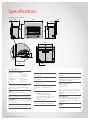
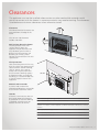
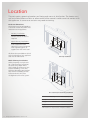
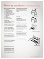
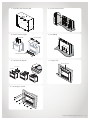
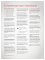
Installation guide
Compact 2
Models: RIBF2N/RIBF2L
Important:
The Compact 2 is not designed to be built directly into a
combustible opening. For combustible opening installations, a
Rinnai zero clearance box and flue kit is mandatory. The Compact
2 is not to be installed, or operated in places where painting is
taking place, or in places such as hair salons where there is a lot
of dust and fluff, and where aerosols are used.
Appliance must be:
--
Installed with a Rinnai supplied flue system.
--
Installed, commissioned and serviced by a licensed
tradesperson in accordance with these instructions and all
applicable local rules and regulations.
Warning
Improper installation, adjustment, alteration, service or
maintenance can cause property damage, personal injury or loss
of life.
For more information about buying, living and servicing of
Rinnai appliances call: 0800 RINNAI (0800 746 624)
Rinnai New Zealand Limited
105 Pavilion Drive, Mangere, Auckland
PO Box 53177, Auckland Airport, Auckland 2150
Phone: (09) 257 3800, Fax: (09) 257 3899
Email: [email protected], www.rinnai.co.nz
:
s
t
n
e
cont
Specification4
Clearances5
Location6
Gas and electrical connection
7
Flueing options9
Flueing guidelines10
Masonry flue installations11
Masonry installation (without flexiliner flue)
13
Zero clearance installation14
Completing heater installation16
Flame pattern18
Wiring diagram19
Specification
All dimensions are in mm.
25
750
227
45
582
645
310
528
43
79
280
Compact 2
Specification summary
Input
= 9-25 MJ/h
Output
= 1.6-5.0 kW
Efficiency
= 73%
Heating area
= up to 78 m²
Gas type
= NG or LPG
Inbuilt radiant/convector, glass
fronted, ceramic log space heater
with forced convection and natural
draft flue system.
Burners
Ember bed and flame burner
Combustion system
Naturally aspirated multi port burner.
Data plate
Inside the appliance on the front right
hand side panel.
Fan
Convection fan tangential 2-speed.
4 | Compact 2 Installation Guide: 11817-A 01-12
Flue (masonry)
Refer page 9.
Noise level
49 dB(A)
Flue (mock chimney)
Refer page 9.
Operation
Push button to light pilot and burners
(low, medium, and high)
Gas connection
½ “ BSPF male flare.
Gas control
Push button combination control
valve.
Glass types
-- Primary: Ceramic glass
-- Secondary: Tempered glass
-- Glass seal material: Woven fibre
glass cord - Hytex® 1000
-- Log set: Ceramic
Ignition
Continuous spark electronic ignition.
Power consumption
High = 20 W
Standby = 0 W
The electrical connection can exit the
appliance from the lower left or right
hand side, or from the rear of the
heater.
Safety devices
Flame failure thermocouple, overheat
switch (bi-metal strip), fan delay
(bi-metal strip), and power failure
protection
Weight
39 kg
Clearances
The appliance must not be installed where curtains or other combustible materials could
come into contact with the heater. In some case curtains may need restraining. The clearances
listed below are minimum clearances unless otherwise stated.
80 mm
Clearances
The side and vertical clearances are
measured from the edge of the
frame.
The 180 mm side clearance
includes side walls.
180 m
m
Wall surface above the heater
The temperature of the wall
surface directly above the
appliance may be elevated, and
may discolour paint finishes or
distort vinyl wall coverings. For
durability of surfaces, please
contact the manufacturer for their
specification.
180 m
m
Floor protection
Heat emanating from this fire may
over time affect the appearance of
some materials used for flooring,
such as, carpet, vinyl, cork or
timber. This may be amplified if
the air contains cooking vapours
or cigarette smoke. To avoid this
occurring, it is recommended that
a mat be placed in front of this
appliance.
Side wall
E
B
C
D
Mantels and surrounds
A mantel and surround are
allowed providing they are outside
the minimum clearances shown.
Hearths
A hearth is not necessary but can
be used for decorative purposes
or protection of sensitive flooring
if required. A hearth must not
obscure the front of the fire.
A
A
Mantel height from edge of frame
80 mm min.
B
Mantel depth at A - 80 mm (vertical clearance)
150 mm max.
For every 50 mm of added mantel depth, there must be an additional 100 mm of vertical
clearance. For example; a mantel depth (B) of 200 mm will require 180 mm (A) of vertical
clearance.
C
Surround from edge of frame
80 mm min.
D
Surround projection at C - 80 mm (side clearance)
250 mm max.
E
Clearance to side wall
180 mm min.
Compact 2 Installation Guide: 11817-A 01-12 | 5
Location
The main points governing location are flueing and warm air distribution. The heater must
not be installed where curtains or other combustible materials could come into contact with
the appliance. In some cases curtains may need restraining.
Enclosure dimensions
The heater must be positioned on
a flat level surface that allows free
movement of the appliance.
--
Masonry installations
Use a slurry of sand and
cement to level the base as
required.
--
Mock chimney installations
The zero clearance box needs
to be supported. Either
construct a base using board
with supporting joists, or
support with the frame itself.
All dimensions provided are critical
to the installation of this appliance
and must be adhered to.
Masonry installation
Mock chimney installations
When preparing a cavity/frame
for a zero clearance installation,
the total cavity depth MUST
also include the thickness of the
external cladding, as the zero
clearance box MUST BE installed
flush with the cladding surface.
Failure to do this will cause
misalignment of the flue system.
Zero clearance (mock chimney) installation
Masonry
Zero clearance
W-width
595-700 mm
685 mm
H-height
550-630 mm
615 mm
D-depth
360 mm*
380 mm
* Min clearance of spigot to back of fireplace is 50 mm
6 | Compact 2 Installation Guide: 11817-A 01-12
Gas and electrical connection
Gas pipe sizing must consider the gas input to this appliance, as well as other gas appliances
in the premises. The gas supply termination is inside the heater, and enters from the rear of
the appliance.
½ ˝ BSP flared nut
The length of the gas supply
termination is measured from the
front of the enclosure, including
the thickness of any cladding
material.
½ ˝ BSP male flare x ½ ˝ barrel union - elbow
Vertical
centre line
Gas supply location
2
Gas supply location
1. Mark off the location for
the vertical centre line of the
heater enclosure.
3
2. To the right of the vertical
centre line, mark off both the
vertical and horizontal location
for the gas supply penetration.
2 = 280 mm to right of appliance centre line
3 = 43 mm from base of enclosure
4 = Gas supply to be terminated 79 mm from the
front of the enclosure
Purging gas supply
Foreign materials and debris
such as swarf, filings etc must
be purged from the gas supply.
Failure to do so may cause damage
to the control valve causing it to
malfunction.
OF
AR URE
E
S
R O
CL
EN
Electrical connection
This appliance has a power cord
with a 3-pin plug supplied. The
power cord passes through the
slot in the lower left or right hand
side of the heater front assembly,
or from the rear panel.
4
FR
ON
(Inc T OF
lud ENC
ing LO
Cla SU
ddi RE
ng)
A ½ “ BSP nut and a ½ “ BSP male
flare x ½ barrel union - elbow are
provided for connection to the gas
supply. They are shipped inside the
engine attached on the gas inlet
connection of the heater.
Gas supply
Gas connection
Rinnai recommends that the
heater is plugged into a 230 V
10 A earthed power point. The
power point must be a minimum
of 300 mm to the side, and MUST
NOT be above the unit.
The electric isolation switch must
be accessible after the appliance
has been installed. The electrical
cord is not fire rated and should
not come into contact with the
fire.
Power cord
Rubber grommet
Electrical connection
Compact 2 Installation Guide: 11817-A 01-12 | 7
Compact 2
Flueing
Flueing options
Masonry - no flexiliner
Masonry - flexiliner
Zero clearance- direct and offset
Zero clearance - offset
Flueing notes
Masonry flueing
Rinnai strongly recommends
the use of a Rinnai flexiliner flue
system. Failure to meet this
criteria may result in an unsafe
situation. Installation without a
flexiliner flue is permissible as
long as the chimney is checked
for soundness and ability to
achieve a good draw. If in doubt
install a Rinnai flexiliner flue
system.
Zero clearance flueing
Natural draft double skin flue.
Termination—an approved
100 mm cowl must be fitted to
all installations.
Rear discharge spigot
43 x 245 mm.
Flue dimensions:
Outer: 150 mm
Inner: 100 mm
For new fireplace installations
(installations into a combustible
opening) a Rinnai zero clearance
box and flue kit is a mandatory
requirement to meet warranty
conditions.
Compact 2 Installation Guide: 11817-A 01-12 | 9
Flueing guidelines
Clearance to combustibles
Minimum clearance from inner
flue to combustible material must
be greater than 25 mm.
Flashings
To top of chimney structure do not
form part of the flue kit and must
be specified.
Flue cowl clearance
To ensure products of combustion
are cleared, adequate clearance
for the building is required.
The flue cowl should have a 500
mm clearance from any part of
the building. This also applies to
steeped and pitched roofs which
should be clear of the ridge line
as shown. Lesser clearances
may provide perfectly adequate
flue systems depending on the
installation. Minimum clearances
are shown in AS/NZS 5601.1, or
NZS 5261*.
Flue length and bends
This is required for adequate
draw, and prevents spill-back of
combustion products that can
cause the safety sensors to shut
down the fire.
Flue terminal locations
Must be compliant with
‘Clearances Required for Flue
Terminals’ from AS/NZS 5601.1, or
NZS 5261* 2003.
Flue is not to terminate under
floors or in a roof space.
Inner flue
Flue
Outer flue
Combustible Material
(must be greater than 25 mm from inner flue)
Self-supporting flue
The weight of the flue system
should not be supported by the
appliance—it should be selfsupporting. Supporting the flue
is usually completed during the
framing stage with flue supports
or straps within the cavity.
Clearance to combustibles
Shared flues
Gas appliances must not be
connected to a chimney or flue
serving a separate fuel burning
appliance.
* NZS 5261 applicable until December
31st, 2012.
Self-supporting flue
--
Minimum flue length
3.6 m vertical. 1.2 m of
vertical flue is required before
any bend or offset.
--
Maximum flue length
Rinnai recommend a
maximum flue height of 8 m.
--
Bends
Maximum of 2 x 45 ° bends.
Flue cowl clearance—500 mm clearance from any part of the building
10 | Compact 2 Installation Guide: 11817-A 01-12
Masonry flue installations
There are two types of masonry flue installations; open chimney and lined chimney. An open
chimney uses the natural draft properties of a sound chimney, and an approved chimney
plate and cowl to provide flueing for the heater. A lined chimney installation is used when the
existing chimney condition is inadequate for an open chimney installation, and uses a Rinnai
flexiliner system to provide flueing for the heater.
Check dimensions of opening
Ensure opening is within the range
provided (p. 6), and if necessary
bring them to the required
dimensions. Also check chimney
height as inadequate height can
affect product performance.
Some installations may require the
chimney height to be extended to
reduce down drafts. Also check
there are no obstructions.
Approved chimney
cowl
Chimney plate
Mortar
Minimum
200 mm
Minimum
3.6 m
Provide a firm, flat, and sealed
base, otherwise noise and
vibration may result. Sealed means
no holes or openings in the fire
place.
Some criteria for checking
chimney soundness
Rinnai strongly recommends
the use of a Rinnai flexiliner flue
system. Failure to meet this criteria
may result in an unsafe situation.
Installation without a flexiliner
flue is permissible as long as the
chimney is checked for soundness
and ability to achieve a good
draw. Some criteria for checking
soundness:
--
All loose/broken bricks must
be replaced or repaired
ensuring the chimney is of
sound construction and does
not leak.
--
Chimney must be swept clean
and be free from soot and
creosote that may have built
up if previously used for a
solid fuel fire
--
Any damper plate must be
fixed in an open position or
removed
--
Any underfloor air supply
to the fireplace must be
completely sealed to prevent
secondary air draw
Minimum
50 mm
Open chimney installation
Approved chimney
cowl
Chimney plate
Mortar
Minimum
200 mm
Adpator
Flexible
chimney
liner
Minimum
3.6 m
Appliance
adaptor
Lined chimney installation
Compact 2 Installation Guide: 11817-A 01-12 | 11
Compact 2
Installation
Masonry installation (without flexiliner flue)
Masonry installation overview
1. Prepare site
2. Unpack heater engine
3. Prepare heater engine
4. Position heater engine
5. Connect the electrical supply
6. Insert heater into fireplace
7. Connect gas
8. Leak test
9. Secure heater
10. Complete installation
1. Prepare site
Ensure the intended enclosure
meets the dimension
requirements, and that the gas
and electrical supplies have been
prepared in accordance with the
information stated on page 7.
2. Unpack heater engine
The heater engine is supplied in
one carton. Check for damage,
and ensure you have the correct
gas type before starting. Do not
install if any damage is evident.
3. Prepare heater engine
Attach the adhesive backed foam
sealing strip (supplied) to the
rear face of the front assembly
mounting panel at approximately
20 mm from the top edge.
The foam strip is intended to form
a seal between the heater and the
fireplace brickwork. If an adequate
seal cannot be formed then
another means of sealing must
be used (e.g. non-combustible
insulation or heat resistant silicon).
Remove, but do not discard the
gas/electrical plate (five screws).
5. Connect the electrical supply
Plug in the 3-pin connector if
electrical connection is inside the
fireplace.
Foam sealing strip
6. Insert heater into fireplace
Carefully move the heater into the
fireplace ensuring the gas supply
pipe and fittings feed into the rear
access hole.
Front assy.
mounting panel
20 mm from top edge
7. Connect gas
Connect gas supply pipe and
fittings to the gas control valve
inlet and tighten.
8. Leak test
Turn the gas on and using a soapy
solution, leak test all appliance
connections. If a leak is present
bubbles will form at the leak point.
When finished remove any residue
with a rag. Prevent any soapy
solution coming into contact with
electrical components.
9. Secure heater
Fasten the heater to the masonry
using appropriate fasteners
(not supplied). There are three
holes across the top of the front
assembly mounting panel and side
panels.
Gas/electrical
access plate
Preparing the heater engine
10. Complete installation
Refer to instructions on page 16.
Securing the heater
4. Position the heater engine
Place the heater engine in front
of the fireplace enclosure. Use a
panel of the cardboard packaging
underneath the heater to help
prevent damage to the flooring.
Compact 2 Installation Guide: 11817-A 01-12 | 13
Zero clearance installation
Zero clearance installation
overview
1. Prepare site
2. Assemble zero clearance box
3. Fit zero clearance box
4. Install flue
5. Unpack heater engine
6. Prepare heater engine
7. Fit cladding
8. Connect flue adaptor
9. Position heater engine
10. Connect electrical supply
11. Insert heater into fireplace
12. Connect flue
13. Secure flue
14. Connect gas
15. Secure heater
16. Leak test
17. Complete installation
1. Prepare site
Ensure the intended enclosure
meets the dimension
requirements, and that the gas
and electrical supplies have been
prepared in accordance with the
information stated on page 7.
Ensure there are no wall studs,
noggins, ceiling joists, wiring, or
other obstruction within the wall,
and/or ceiling cavity where the flue
is to be located.
2. Assemble zero clearance box
Refer separate assembly
instructions included with the zero
clearance box.
3. Fit zero clearance box
Slide assembled zero clearance
box into the cavity, ensuring the
gas and electrical supplies are
accessible.
Secure the zero clearance box
into the cavity with appropriate
fasteners (not supplied).
4. Install flue
Install zero clearance flue system
components.
14 | Compact 2 Installation Guide: 11817-A 01-12
5. Unpack heater engine
The heater engine is supplied in
one carton. Check for damage,
and ensure you have the correct
gas type before starting. Do not
install if any damage is evident.
6. Prepare heater engine
Attach the flue guide rails
(supplied with the zero clearance
box) to the top of the heater
engine using the four predrilled
holes and four screws supplied.
Remove (do not discard) the flue
access plate, and the gas/electrical
access plate.
7. Fit cladding
Before installing the heater ensure
the cladding for the front of
the enclosure has been fitted.
Remember, the cladding MUST
BE installed flush with the zero
clearance box. Failure to do this
will cause alignment problems
with the flue.
8. Connect flue adaptor
Connect the flue adaptor* to the
engine by aligning the guide rails
with the guide plate* of the flue
adaptor. Slide the flue adaptor in
until the guide plate is fully home
against the rear of the flange at
the top of the heater.
* Supplied with the zero clearance box.
9. Position heater engine
Place the heater engine in front
of the fireplace enclosure. Use a
panel of the cardboard packaging
underneath the heater to help
prevent damage to the flooring.
10. Connect the electrical
supply
Plug in the 3-pin connector if
electrical connection is inside the
fireplace.
11. Insert heater into fireplace
Carefully move the heater into the
zero clearance box, ensuring the
gas supply and fittings feed into
the rear access hole.
12. Connect flue
The weight of the flue system
should not be supported by the
appliance—it should be selfsupporting. Supporting the flue
is usually completed during the
framing stage with flue supports
or straps within the cavity.
13. Secure flue
Replace the flue access plate, and
secure the guide plate of the flue
adaptor to the flue access plate
with the two screws supplied. Resecure the flue access plate to the
heater (three screws).
14. Connect gas
Connect gas supply pipe and
fittings to the gas control valve
inlet and tighten.
15. Secure heater
Fasten the heater to cladding
surface using appropriate fasteners
(not supplied). There are three
holes across the top of the front
assembly mounting panel and side
panels.
16. Leak test
Turn the gas on and using a soapy
solution, leak test all appliance
connections. If a leak is present
bubbles will form at the leak point.
When finished remove any residue
with a rag. Prevent any soapy
solution coming into contact with
electrical components.
17. Complete installation
Refer to instructions on page 16.
2. Assemble zero clearance box
3. Fit zero clearance box
6. Prepare heater engine
7. Fit cladding
Guide rails
Flue access plate
K
Gas/electrical access plate
8. Connect flue adaptor
13. Secure flue
Flue acccess plate
Flue adaptor
Rail guides
15. Securing the heater
Compact 2 Installation Guide: 11817-A 01-12 | 15
Completing heater installation
Heater installation overview
1. Remove burner box glass
2. Unpack log set and granules
3. Install log set and granules
4. Replace burner box glass
5. Turn on electrical supply
6. Check burner pressures
7. Attach frame assembly
8. Complete installation checklist
1. Remove burner box glass
Loosen, but do not remove the
two retaining screws for the
bottom burner box clamp.
While supporting the burner box
glass panel, completely unscrew
and remove the two remaining
screws and the top burner box
clamp. Lift burner box glass panel
and place aside.
2. Unpack log set and granules
Carefully unpack the log set from
the packaging material and inspect
for damage. If any damage is
evident, do not continue with the
installation.
The satchel containing the burner
granules is taped to the outside
of the foam packing that contains
the log set.
3. Install log set and granules
Do not remove the burner from
the heater to install the log set.
Use extreme care when handling
the log set as it is fragile and will
damage easily.
To position correctly, hold the
log set at approximately 45 °
directly in front of the burner box.
Maintain this angle and place the
front feet of the log set behind the
unpainted inner horizontal steel lip
of the combustion chamber. Take
care to ensure the ends of the log
set do not touch the burner box
walls.
To set the log set into the final
16 | Compact 2 Installation Guide: 11817-A 01-12
position, rotate the back of the log
set down, using the location of the
front feet as pivot points, until it is
sitting flat on the rear burner.
Check the correct position of
the log set before installing the
granules. Ensure the log set is
firmly seated in the centre of the
burner box and not touching the
side walls, and that the ports are
clear of any debris that may have
occurred during installation.
Carefully place (do not pour) the
granules over and around the
front burner ports. It is beneficial
that the gas jet is diffused by the
granules. This will reduce any
candling effect of the flame and
enhance the realistic log-burning
look of the heater.
CAUTION
Do not force, or block
the burner ports with the
granules.
Do not place any granules
on the rear burner.
4. Replace burner box glass
5. Turn on electrical supply
6. Check burner pressures
Turn gas supply on, and refer to
the data plate on the appliance for
the correct gas pressure settings.
Remove the pressure test point
screw and attach a manometer to
the test point situated on the front
of the injector block.
Light the heater, select the
high heat setting, and check
the pressure. If adjustments are
necessary, the regulator is situated
on the front of the gas control.
After checking pressures, turn the
unit off, remove manometer, and
replace test point screw.
Turn the heater on and off a few
times to check ignition. When
you are satisfied that the heater
is working correctly, re-attach the
gas/electrical access plate (five
screws), and check the flame
pattern.
7. Attach frame assembly
Locate and remove the two 8 g x
10 mm frame assembly securing
screws. These are positioned in the
frame mounting tabs on the gas/
electrical access plate.
Carefully pick up the frame
assembly taking care not to tilt it
on its edge as the glass may slide
out of the stand-off posts.
Position the top fold over the
frame assembly mounting tabs
and gently push the lower edge of
the frame assembly until it is flush
at the edges.
Fit and tighten the two frame
retaining screws and the frame
mounting tabs on the heater.
8. Complete the installation
checklist
Complete the installation and
commissioning checklist in the
customer operation guide, and
make sure you leave the guide
with the customer. Explain to the
customer about the use and care
of the heater, and ensure they
understand the instructions and
operation of the appliance.
If the appliance cannot be made
to perform correctly please contact
Rinnai.
1. Removing the burner box glass panel
3. Install log set and granules
Retaining screw
Bottom burner
box glass
clamp
Retaining screw
6. Check burner pressures
Front feet as
pivot points
7. Attach frame assembly
Test point screw
Frame
mounting
tabs
Frame
assy. securing
screws
Gas/electrical
access plate
Regulator
7. Attach frame assembly
7. Attach frame assembly
Screws through
the frame
Top fold
Frame assy
mounting tabs
Rear view of
installed frame
Frame assy
mounting tabs
Compact 2 Installation Guide: 11817-A 01-12 | 17
Flame pattern
It may take approximately two hours of operation for the logs to achieve their full flame
pattern and glow. During the initial burning in period, some smoke and smell may be
experienced. The appliance should run on the high setting in a well ventilated room until
these dissipate. It is important to check the flame pattern during this time.
Abnormal flame pattern
Abnormal flame performance and/
or pattern can indicate a problem
with your fire, such as blocked gas
injectors, or log set (burn media)
has shifted from when the fire
was first installed. There are some
warning signs that could indicate a
problem.
--
Unusual smell from the
appliance
--
Continued difficulty or delay in
establishing a flame
--
Flame appears either very
short or very long
--
Flame only burns part way
across the burner
--
Severe soot building up on the
inside of the glass door
Important
It is the responsibility of the
installer to check that under
normal conditions of the
appliance, all flue gases are
exhausted to the outside
atmosphere, and that there is no
spillage of combustion gases into
the room.
If the appliance cannot be made
to perform correctly please contact
Rinnai.
18 | Compact 2 Installation Guide: 11817-A 01-12
Normal flame pattern
Abnormal flame pattern
Wiring diagram (10153)
TC
( +)
FAN
(-)
OHS
FAN S WITC H
B L HI/ LOW
(MIC R O)
1 BL
2 R
R
3 W
W
SV
W
FAN S WITC H
ON/OFF
(T HE R MAL)
+ -
2
1
S PAR KE R
BR
BL
BL
E LE CTR ODE
W
BL
BR
220~240 v
50 Hz
G /Y
R
BL
BR
W
G/Y
2
1
BL
W
1
2
BL
W
IGN S WITC H
(MIC R O)
Red
Blue
Brown
White
Green/Yellow
OHS Overheat Switch
SV Solenoid Valve
TC Thermocouple
Compact 2 Installation Guide: 11817-A 01-12 | 19
Experience our innovation
Rinnai.co.nz 0800 746 624
https://www.youtube.com/rinnainz