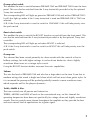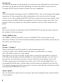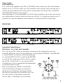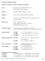
1
GA-30RV
GA-60RV
GA-30RVH
O P E R A T I N G
INSTRUCTIONS
INTRODUCTION
Congratulations on your purchase of a Gibson Super ‘Goldtone’ valve guitar amplifier.
Please take a few minutes to read this owners manual so you may fully understand the
extensive capabilities of this unit. With a little care your new amplifier should provide
you with years of satisfactory service.
The Super ‘Goldtone’ range currently consists of the following products:
GA-30RV
GA-60RV
GA-30RVH
SGT Cabinet
30 watt Class A 1x10 + 1x12 combo
60 watt Class A/B 2x12 combo
30 watt Class A head
2x10 + 2x12 Mono/Stereo speaker cabinet
The main preamp functions on all models are more or less the same, with different valve
power stages and/or speaker configurations used in each particular unit. All features and
differences between models are described further on.
The circuit topology has been based on traditional guitar amplifier designs, with new
ideas incorporated where beneficial.
The complete signal path; preamp, effects loop, reverb and power stage, on all models is
100% valve.
The switching circuitry for the different functions is all based around momentary switches
controlling CMOS logic devices which then switch relays or FET’s within the audio
circuitry. This provides very low switching noise, excellent sonic performance and the
ability to switch all the functions from multiple sources.
All Power and Output transformers and Chokes are custom made for maximum
performance using high grade laminations. Windings are resin soaked and made to pass
international approvals.
A highly regulated DC supply is used for heater filaments in all preamp valves for
minimal hum levels.
Where appropriate an external biasing facility is featured - this enables techs to
check/reset output bias at any time without removing the chassis. This also enables the
use of several different valve types including EL34, 6L6, 6550 and KT88.
Internal wiring and glass epoxy circuit board layouts use multiple return, star earthing, for
low noise and hum. All audio sections have been laid out for maximum sonic
performance using ‘point to point’ wiring principles.
Porcelain valve sockets and gold plated jack sockets are used exclusively throughout.
3
FAST TRACK GUIDE AND SWITCH ON SEQUENCE
1. Check that the POWER switch on the rear panel is set to OFF and that the unit has
the correct speaker load connected.
2. Connect the unit to an appropriate mains power point with the mains lead provided.
We also recommend that the MASTER volume is turned down to zero before switch
on or switch off purely to prevent any unwanted noises from being amplified loudly.
Switch POWER switch to the STANDBY position.
3. While the unit is warming up (allow at least one minute), connect your instrument to
the INPUT socket on the front panel and connect any effects units that may be used.
4. Switch POWER switch from STANDBY to ON.
5. Set all front panel controls to half way as a starting point and then adjust to taste.
6. After use, switch to STANDBY and then OFF.
FULL OPERATING INSTRUCTIONS
FRONT PANEL
Preamp features and controls
The preamp section is 100% valve and consists of two parallel preamp channels and a
BOOST function that can be used on either channel. This allows FOUR different sounds
to be selected from either the front panel or 2-way footswitch. Using the optional 5-way
foot controller allows both channels to be used at once with BOOST on or off giving a
total of SIX available preamp sounds.
A regulated DC supply is used throughout the preamp for the cathode heaters, this
massively reduces any hum picked up within the preamp to extremely low levels, even
when set for high gain.
When first switched on the unit should default to PREAMP ONE (green LED), BOOST off
(LED off), EFFECTS off and REVERB on.
4
Input
A single jack socket is provided for connection to your instrument. This has a high
impedance input which allows for perfect matching to both passive and active guitars.
When there is no jack inserted into the input, the output of the preamp to the power
stage is muted; this prevents any noise from being amplified when the unit is not in use.
N.B. Please read the section on the EFFECTS LOOP if a SUPER ‘GOLDTONE’ is to be
used as a slave amp for a stereo set-up.
Preamp select switch
This enables the user to switch between PREAMP ONE and PREAMP TWO from the front
panel. This can also be switched from the 2-way footswitch provided or by the optional
5-way foot controller.
The corresponding LED will light up green for PREAMP ONE and red for PREAMP TWO.
It will also light up amber if the 5-way footswitch is used and PREAMP 0NE & TWO are
selected.
N.B. If the 2-way footswitch is used to switch to CHANNEL 2 this will take priority over
the push switch.
Boost select switch
This enables the user to switch the BOOST function on and off from the front panel. This
can also be switched from the 2-way footswitch provided or by the optional 5-way foot
controller.
The corresponding LED will light up red when BOOST is selected.
N.B. If the 2-way footswitch is used to switch on BOOST this will take priority over the
push switch.
Preamp one
This channel has been voiced primarily for clean sounds with the controls at low to
halfway settings, but with higher settings it can be driven harder for classic slightly
overdriven blues tones or a vintage style crunch.
Using the BOOST function further increases the sonic capabilities.
Volume
This sets the level of PREAMP ONE and also has a large effect on the tone. From low to
medium settings the sound is bright and clean which will suit most clean guitar styles. As
it is increased the preamp will be pushed gradually towards a more overdriven tone,
which responds well to the players dynamics.
Treble, Middle & Bass
The tone controls are all passive and interactive.
TREBLE, MIDDLE and BASS all work in the conventional way, on this channel the
operating frequencies have been set specifically for vintage clean and slightly overdriven
sounds. Passive controls were chosen throughout the amplifier as they provide the best
and most natural kind of equalisation for a guitar signal.
5
Preamp two
This channel has been voiced primarily for overdriven tones although the overall sound
produced can be altered radically depending on where the different controls are set.
Using the BOOST fuction further increases the sonic capabilities.
Gain
This control adjusts the degree of drive in PREAMP TWO. Due to the design of the highly
responsive all valve preamp this allows adjustment of the tone from clean, through
crunch, to very dirty, adding the BOOST will then increase the sustain even further. Total
amount of gain available should be enough for even the most extreme rock styles. This
preamp is also very responsive to the players dynamics and use of the volume on the
guitar.
Level
This control sets the overall output level for PREAMP TWO and can be used to balance
the volume of the two preamps.
Treble, Middle & Bass
The TREBLE, MIDDLE and BASS controls on PREAMP TWO are also passive and
interactive, however, for this preamp the operating frequencies have been specifically set
for mainly over driven tones.
Reverb
Preamp 1, Preamp 2
These control the level of the reverb for each preamp respectively.
On the GA-30RV, and GA-60RV models the effect is produced by a six spring
ACCUTRONICS reverb tray in the cabinet.
The optional 5-way foot controller can be used to switch the reverb effect on and off.
N.B. Due to the amount of reverb available, in some extreme settings; i.e. loud, lots of
gain and lots of reverb, there may be occasions when the reverb springs start to self
oscillate, producing a low pitched tone on their own. If this should happen then it is
recommended that the gain, volume and/or reverb settings are adjusted to prevent this.
N.B. If both preamps are selected using the 5-way foot controller the reverb level will be
controlled by the PREAMP 2 control.
Master Volume
This sets the level of signal sent to the power amp and consequently the overall volume
of the amplifier.
6
Power Switch
Off/Standby/On
This switches the amplifier from OFF to STANDBY mode, where only the valve filament
heaters are on, to ON for actual use. This should be used correctly every time the unit is
used to prevent problems with valves and to increase their life. Please refer to SWITCH
ON SEQUENCE earlier in the manual.
After switching of it is recommended, as with all valve amplifiers, that it does not receive
any sudden physical shocks while the valves are still hot, i.e. through moving the unit. If
possible try to give the amplifier a few minutes to cool down before transporting it.
REAR PANEL
GA-30RV & GA30RVH
GA-60RV
Footswitch Control Sockets
DIN Socket - For 5-Way Foot Controller
This is an 8 pin DIN connector that when connected to the optional five way foot
controller allows the user to do the following:- switch between PREAMP 1 and PREAMP
2, switch BOOST on and off, switch both preamps
on, switch EFFECTS LOOP on and off and REVERB
on and off.This socket may also be used to connect
the SUPER “GOLDTONE” to an external (MIDI)
switching unit, with an appropriate lead dependant
on particular device used.
Bear in mind that the SUPER “GOLDTONE”
internal switching is designed to respond to
momentary (non latching) switching and that
the external switching unit should be set for this.
For more advice on this please contact the
Service Dept. or distributor in your territory.
PIN CONNECTION FOR
8 WAY DIN CONNECTOR
7
Jack Socket - For 2-Way Footswitch (Preamp1/2, Boost on/off)
This is a stereo 1/4” jack socket for connection to the supplied two way latching
footswitch, that enables the user to footswitch between preamp 1 and 2, and to operate
the BOOST function remotely.
This can be used as well as the optional five way foot controller if desired, however, due
to the 2 way footswitch being a latching type, when switched on it will take priority over
any other switch.
Effects Loop
This has sockets for SEND and RETURN and a level for each, as well as a switch for
SERIES or PARALLEL configuration.
Send, Level
The SEND socket is for connection to the input of effects units. By correctly adjusting the
LEVEL control, this can drive floor type battery powered effects pedals or 19” rack type
studio effects units.
The actual setting of the LEVEL control will depend on several things:- the output of the
guitar, the preamp settings and the level needed to drive the particular effects unit.
The general idea is to set the level as high as possible, (which improves signal/noise ratio)
without creating distortion.
As a guide, if floor type pedals are used the LEVEL will probably need to be set
somewhere between ‘0’ and ‘5’, whereas if studio rack type devices are used it can be set
higher up so that the level indicators on the effects unit reach their maximum point
during peaks in the playing.
Return, Level
The RETURN socket is for connection to the output of effects units. The function of the
LEVEL will depend on whether the loop is set to SERIES or PARALLEL configuration.
In PARALLEL operation the LEVEL control will set the amount of effect signal mixed in
with the straight, un-effected ‘dry’ signal when the effects loop is switched in, it has no
effect on the dry signal.
In SERIES operation the LEVEL control will set the overall level of the total signal (sent
from the effects unit) when the effects loop is switched in.
Unless otherwise desired, it is best to set this so that when switching the effects loop on
of off there are no great leaps in volume difference.
Series/Parallel Switch
The SERIES/PARALLEL switch alters the configuration of the effects loop.
In SERIES mode the whole signal comes out of the amp, into the effects unit and then
back into the amp, where as in PARALLEL mode the effected signal is mixed in with
8 the original dry signal, thus ensuring tonal purity of the dry signal.
The choice of which mode to use will depend on what kind of effects unit is used and
what overall effects is desired. But generally if time delay effects are used, such as delay
(echo), reverb, chorus, flanging, phasing, etc., then the PARALLEL setting is usually
preferred. If volume or EQ related effects are used, such as overdriven/distortion,
compression, graphic equalisation, wah-wah or volume pedals, or if a multi-effects unit is
used with a combination of time delay and volume related effects, then it is usually best
to set the switch to SERIES. There are no rules, it is best to experiment and see what you
prefer.
If PARALLEL configuration is used then if possible it is recommended that the dry/direct
signal from the effects unit is turned to minimum or off.
Ultimately there are no rules as to how to use effects, it is all down to the players
personal preference and will also depend on what actual effects units are being used.
Indeed, although the effects loop is generally accepted as the best place to add effects,
both technically and sonically, a lot of guitarists still prefer to put at least some of their
effects before the amp, particularly, wah-wah or volume pedals, auto wahs/envelope
filters or compressors.
Therefore, the only right way of doing this is to experiment with all your equipment and
find what suits you best.
If two Super “Goldtones” are used in a stereo set up where the SEND from one amplifier
is sent into the effects processor and the left and right outputs are fed back into the
RETURN on each amp, a jack plug of some kind will need to be inserted into the INPUT
to ‘un-mute’ the amplifier. The ‘slave’ amp should also preferably be set to ‘SERIES’ with
all the controls on CHANNEL1 and CHANNEL 2 turned down.
For more advice on this please contact the Service Dept. or distributor in your territory.
Effects Loop Select Switch
This enables the user to select or deselect the effects loop from the rear panel.
It can also be selected by the optional 5-way foot controller.
Power Amp Sections
Currently, within the Super “Goldtone” range, two different power amp sections are used.
The GA-30RV and GA-30RVH are each powered by four EL84/6BQ5’s configured for
CATHODE BIASED CLASS A, WITHOUT any NEGATIVE FEEDBACK. This is the
traditional arrangement for a guitar amplifier of this type and will produce at least 30
watts with the valves supplied.
The GA-60RV is powered by two EL34’s configured for GRID BIASED CLASS A/B. This is
the traditional arrangement for a guitar amplifier of this type and will produce 60 watts
with the valves supplied. Other octal based output valves such as KT88, 6L6 and 6550
may also be used if biased correctly.
9
Speaker Outputs
The GA-30 models have three 1/4” jack sockets for connection to 8Ω or 16Ω loads. The
two 8Ω sockets are in parallel. The GA-60 has an additional 4Ω output.
On the combo models the two 8Ω outputs are connected to the two internal 16Ω
speakers, however other cabinets may be used for different sounds/occasions as desired.
When using other extension speaker cabinets the overall effective impedance should be
correctly worked out and the appropriate socket(s) used.
Impedance Formula
For the two cabinets in parallel this can be done as follows:ZT (total impedance) = Z1 x Z2
Z1 + Z2
Therefore, as an example, if two 16Ω cabinets are used,
16 x 16 = 256 = 8
16 + 16 32
For more advice on this please contact the Service Dept. or distributor in your territory.
Output Biasing (GA-60RV)
Do not even attempt to make any adjustments to this before reading and understanding
this section thoroughly. As with any power amplifier, incorrect biasing can result in the
complete electronic destruction of the output devices, in this case expensive valves. As
stated on the WARRANTY FORM, valves are not covered by the standard two year
warranty except under certain conditions at the discretion of GIBSON.
If you are in any doubt as to what you are doing refer the unit to an appropriate
electronics service centre.
The holes in the chassis marked BIAS MEASUREMENT and BIAS ADJUST allow the
biasing of the output valves to be checked or reset easily and safely if necessary. It also
allows the use of several different types of output valve including EL34, KT88, 6L6 and
6550.
On a new unit the biasing will be factory set for the particular set of valves supplied with
the amplifier. Although this should not need to be adjusted unless a new set of output
valves is fitted, on all amplifiers as valves age their bias requirements may change.
10
There are several methods that are used to bias valve amplifiers, the following is one of
the easiest and ensures that the output valves do not draw too much current which can
result in thermal runaway.
To check or reset bias on currently installed valves:1. Ensure unit is correctly loaded (speaker is connected). Connect to mains, switch on
(STANDBY) and allow to warm up for at least one minute.
2. Ensure that the MASTER control is turned to zero and switch from STANDBY to ON.
3. Set voltmeter to 200mV DC range. Insert black probe into the 0V hole and red probe
into V1. There should be a reading of 33mV (+/-3mV) on the voltmeter. If necessary,
using a trimmer tool or small flat bladed screwdriver carefully rotate the appropriate
BIAS ADJUST control to give the correct reading on the voltmeter.
4. Now insert black probe into V2. The reading should be as close to 0mV as possible
(+/-1mV). If necessary, using a trimmer tool or small flat bladed screwdriver carefully
rotate the appropriate BIAS ADJUST control to give the correct reading on the
voltmeter.
5. Repeat steps 3 & 4 until no more adjustment is required.
To install new valves and bias amplifier:1. Ensure unit is disconnected from mains supply and that the valves have had time to
cool down.
2. Either remove front grill or complete amplifier assembly and carefully remove
old valves.
3. Install new valves making sure all are inserted correctly.
N.B. Only use matched sets of output valves.
4. Using trimmer tool turn BIAS ADJUST controls fully anti-clockwise.
5. Ensure unit is correctly loaded (speaker is connected). Connect to mains, switch to
STANDBY and allow to warm up for at least one minute.
6. Ensure that MASTER controls are turned to zero and switch from STANDBY to ON.
7. Set voltmeter to 200mV DC range. Insert black probe into the 0V hole and red probe
into V1 probe.
8. Using trimmer tool carefully rotate the appropriate BIAS ADJUST control to give the
correct reading on the voltmeter as shown below.
EL34
KT88
6L6
6550
5881
33mV
37mV
28mV
37mV
30mV
(+/(+/(+/(+/(+/-
3mV)
3mV)
3mV)
3mV)
3mV)
11
The above values are a guideline but should be OK for most brands of valves, although
the bias point for any amplifier is somewhat subjective. Increasing the values shown may
improve the tone but will make the valves run hotter, whereas lower values will increase
valve life and reliability.
9. Now insert black probe into V2. The other BIAS ADJUST control should now be
adjusted to give a reading on the voltmeter as close to 0mV as possible (+/-1mV).
10. Repeat steps 7, 8 & 9 until no more adjustment is required.
For more advice on this please contact the Service Dept. or distributor in your territory.
The output valves on the GA-30 do not require biasing to be manually set due to the
CATHODE SELF BIAS design of the output stage. Therefore to change valves simply
follow points 1, 2 and 3 immediately above.
IEC Socket/Mains Fuse
This is for connection to universally used IEC mains leads to connect to appropriate
domestic mains supply.
In the event of having to replace the mains fuse always use the same fuse rating and type
as marked on the unit’s rear panel. Using one of a higher rating will invalidate the
warranty.
If after replacement the mains fuse should blow a second time, immediately refer the unit
to an approved service engineer for checking.
Super “Goldtone” Cabinet Instructions
The Super “Goldtone” speaker cabinet incorporates a sealed (infinite baffle) 2x12”
bottom, with two Celestion Vintage 30 speakers, and an open backed 2x10” top, with
two Celestion Vintage 10’s.
The power rating of these individually is 60 watts RMS, therefore the power rating of the
whole cab will be 240 watts RMS.
The rear panel sockets and switch allow the cabinet to be configured as either a 4Ω
mono cab, a 16Ω mono cab or a 2 x 8Ω stereo cab. To prevent serious damage check
that the correct impedance is set on both amplifier and the speaker cabinet each time
that they are used. Also make sure that any cables used to connect to the cabinet are
proper speaker cables (NOT GUITAR/INSTRUMENT CABLES) and that they are in good
working order.
When set to 8Ω stereo, a separate amplifier can drive into each of the sockets, however,
when set to mono, either 4Ω or 16Ω, only one of the two sockets should be used at
once. The likely result of driving two amplifiers into the cabinet when set to this
configuration could be the destruction of both the amplifiers and speakers.
12
TECHNICAL SPECIFICATIONS
SUPER “GOLDTONE” GA-30RV, 6A-60RV & GA-30RVH
Input
Impedance 1MΩ, PREAMP SELECT and
BOOST SELECT push switches
Channel 1
VOLUME, TREBLE, MIDDLE & BASS
Channel 2
GAIN, LEVEL, TREBLE, MIDDLE and BASS
Reverb
Valve driven ACCUTRONICS tray with separate controls
for each preamp.
Effects Loop
SEND - Impedance ~10KΩ
LEVEL variable (nominally -20 to 0dBu)
SERIES/PARALLEL push switch
Footswitch Control
1/4” Jack socket for dual latching footswitch
8 way DIN socket for optional 5 way non latching footswitch
Speaker Outputs
GA-30RV
GA-60RV
GA-30RVH
Speaker Configuration GA-30RV
GA-60RV
Power Amp Control
GA-60RV
Power Output
GA-30RV
GA-60RV
GA-30RVH
3 x 1/4” jack sockets (8Ω, 8Ω, 16Ω)
4 x 1/4” jack sockets (4Ω, 8Ω, 8Ω,16Ω)
3 x 1/4” jack sockets (8Ω, 8Ω, 16Ω)
1x10” and 1x12” (Celestion Vintage 10
and Vintage 30
2x12” (Celestion Vintage 30)
OUTPUT BIASING test points and
BIAS ADJUST trimmers
~30 watts RMS Class A
~60 watts RMS Class A/B
~30 watts RMS Class A
Factory Fitted Valve Compliment
GA-30RV
5 x 12AX7/ECC83’s ,2 x 12AT7/ECC81’s and 4 x EL84’s
GA-60RV
5 x 12AX7/ECC83’s ,2 x 12AT7/ECC81’s and 2 x EL34’s
GA-30RVH
5 x 12AX7/ECC83’s ,2 x 12AT7/ECC81’s and 4 x EL84’s
Valve orientation is marked on the top of the chassis
13
SUPER “GOLDTONE” CABINET
Speaker Configuration 2x12” closed back (bottom) + 2x10” open back (top)
(2 x Celestion Vintage 30 and 2 x Vintage 10)
Individual Speaker Specifications
SIZE
POWER
SENSITIVITY
HANDLING (1W @ 1m)
RESONANT FREQUENCY
FREQUENCY RESPONSE
MAGNET
WEIGHT
Celestion Vintage 30
12”
60W
100dB
70Hz
70Hz-5KHz
50oz
Celestion Vintage 10
10”
60W
97dB
80Hz
80Hz-5KHz
27oz
Dimensions
GA-30RV
GA-60RV
GA-30RVH
SGT cabinet
W690mm / H500mm /
(~271/4” / 193/4” / 91/2”)
W730mm / H500mm /
(~283/4” / 193/4” / 91/2”)
W645mm / H220mm /
(~251/2” / 83/4” / 11”)
W690mm / H690mm /
(~271/4” / 271/4” / 12”)
D240mm
D240mm
D275mm
D300mm
Where necessary add height:-
40mm to include handle
20mm to include feet
80mm to include castors
Weight
~33Kg
~36Kg
~20Kg
~40Kg
14
GA-30RV
GA-60RV
GA-30RVH
SGT cabinet
(~73lbs)
(~80lbs)
(~44lbs)
(~88lbs)
SAFETY INSTRUCTIONS
CONSIGNES DE SECURITE
Warning
For continued protection against the risk of fire, replace fuses only with fuses of the same type
and rating.
To reduce the risk of fire or electric shock, do not expose this equipment to rain or moisture.
In the event of a suspected malfunction, always refer this equipment to a qualified service
engineer.
This apparatus must be earthed. The wires in this mains are coloured in accordance with the
following code:-
Attention
Pour une protection continue contre les incendies, ne remplacez les fusibles que par des fusibles
du mÍme type set du mÍme courant nominal.
Pour réduire le risque díincendie ou de décharge électrique, níexposez jamais cet équipement à la
pluie ou à líhumidité.
Si vous soupÁonnez une défaiilance, faites toujours appel à un ingénieur qualifié.
Cet appareil doit Ítre mis à la masse. Les fils de cette conduite díamenée de secteur sont colorés
selon le code suivant:
Green& Yellow - Earth
Blue - Neutral
Brown - Live
Vert & Jaune - Masse
Bleu - Neutre
Marron - Tension
As the colours of the wires in the mains lead of this appliance may not correspond with the
coloured markings identifying the terminals in your plug, proceed as follows:The wire which is coloured Green & Yellow must be connected to the terminal in the plug which
is marked with the letter E or by the earth symbol or coloured green or Green and Yellow.
The wire which is coloured Blue must be connected to the terminal which is marked with the
letter N or coloured Black.
The wire which is coloured Brown must be connected to the terminal which is marked with the
letter L or coloured Red.
If A 13 amp (BS1363) plug is used a 13 amp fuse must be fitted, or if any other type of plug is
used a 15 amp fuse must be fitted either in the plug or adaptor or at the distribution board.
Etant donné que les couleurs des fils de la conduite díamenée de secteur de cet appareil risquent
parfois de ne pas correspondre aux couleurs identifiant les bornes de votre fiche, procédez
comme suit:
Le fil Vert & Jaune doit Ítre relié à la borne de la fiche marquée de la lettre E, du symbole de terre
ou colorée en Vert set Jaune.
Le fil Bleu doit Ítre relié à la borne marquée de la lettre N ou colorée en Noir.
Le fil Marron doit Ítre relié à la borne marquée de la lettre L ou colorée en Rouge.
Si vous utilisez une fiche 13 amp (BS1363) vous devez utiliser un fusible 13 amp. Si vous utilisez
un autre type de prise, installez un fusible 15 amp dans la prise, dans líadaptateur ou dans le
tableau de distribution.
EMC Warning
It is inherent in the design of a loudspeaker and in the design of guitar pickups that they should
emit or be affected by electro magnetic fields. Loudspeaker enclosures should not be used less
than 2 metres away from equipment which is likely to be affected by electro magnetic
interference.
Likewise, guitars fitted with electro magnetic pickups should not be used less than 2 metres away
from any source of electro magnetic emissions such as loudspeakers.
Emissions from loudspeakers are dependent on the frequency characteristic of the drive unit.
Levels were measured direct from the drivers of 30 dBuV.
These levels are reduced to a safe level at a distance of 1.27 metres from the drivers.
Compatibilité électromagnétique - avertissement
La conception d’un haut-parleur set des pickups de guitare est telle qu’ils sont affectés par des
champs électromagnétiques ou en émettent les enceintes de haut-parleur ne devraient pas étre
utilisées à moins de 2 mètres de l’équipement susceptible d’être affecté par les parasites
électromagnétiques.
Les émissions en provenance de haut-parleurs dépendent de la caractéristique fréquentielle de
l’émetteur piloté.
De même, les guitares équipées de pickups électromagnétiques ne devraient pas être utilisées à
moins de 2 mètres de toute source d’émissions électromagnétiques telles que des haut-parleurs.
Les niveaux ont été mesurés directement à partir des drivers de 30 dBuV.
Ces niveaux sont réduites à un niveau sûr à une distance de 1,27 mètre des drivers.
SICHERHEITS-ANWEISUNGEN
INSTRUCCIONES DE SEGURIDAD
Warnung
Zum fortdauernden Schutz gegen Feuerrisiken die Sicherungen nur durch Sicherungen desselben
Typs und derselben Nennleistung austauschen.
Um das Risiko von Feuer oder Elektroschock zu reduzieren, dieses Gerät keinem Regen und
keiner Feuchtigkeit aussetzen.
Im Fall eines vermuteten Defekts muß dieses Gerät einem qualifizierten Service-Techniker
übergeben werden.
Dieses Gerät muß geerdet werden. Die Drähte im Stromkabel wurden dem folgende Code nach
koloriert:
Advertencia
Para una protección continua contra el riesgo de incendio, reemplace siempre los fusibles con
otros del mismo tipo y valor.
Para reducir el riesgo de incendio o descarga eléctrica, no exponga este equipo a la lluvia o a la
humedad.
En caso de que sospeche que exista un desperfecto, refiera siempre este equipo a un ingeniero
de servicio calificado.
Este aparato debe tener conexión a tierra. Los cables de esta toma se colorean según el código
siguiente:-
Grün & Gelb - Erde
Verde & Amarillo - Tierra
Blau - Neutral
Braun - Stromführend
Da die Farben der Drähte dieses Geräts nicht notwendigerweise den Farbmarkierungen der Pole
in Ihrem Stecker entsprechen, sollten Sie wie folgt vorgehen:
Der grün/gelbe Draht muß an den Pol im Stecker angeschlossen werden, der mit dem
Buchstaben E oder dem Erde-Symbol oder der Farbe Grün oder Grün/Gelb markiert ist.
Der blaue Draht muß an den Pol angeschlossen werden, der mit dem Buchstaben N oder
schwarz markiert ist.
Der braune Draht muß an den Pol angeschlossen werden, der mit dem Buchstaben L oder rot
markiert ist.
Falls ein 13 amp (BS1363) Stecker benutzt wird, muß eine 13 amp Sicherung eingesetzt werden;
und falls ein Stecker anderer Art benutzt wird, muß eine 15 amp Sicherung entweder im Stecker
selbst oder an der Verteilertafel eingesetzt werden.
EMC Warnung
Es liegt im Design eines Lautsprechers und im Design von Gitarrenaufnehmern, daß sie
elektromagnetische Felder abgeben oder von solchen beeinflußt werden. Lautsprechergehäuse
sollten daher nicht in unter 2 Metern Entfernung von Geräten benutzt werden, die durch
elektromagnetische Störungen beeinflußt werden könnten.
Auch sollten Gitarren, die mit elektromagnetischen Aufnehmern ausgestattet sind, nicht in unter
2 Metern Entfernung von Quellen elektromagnetischer Emissionen, wie z.B. Lautsprechern,
benutzt werden.
Die Lautsprecheremissionen sind von der Frequenzcharakteristik der Treiber-Einheit abhängig.
Die Werte wurden direkt von den Treibern von 30 dBuV gemessen.
Diese Werte reduzieren sich in einer Entfernung von 1,27 Metern von den Treibern auf ein
sicheres Maß.
Azul - Neutro
Marrón - Vivo
Como los colores de los cables de la toma principal de este aparato pueden no corresponder con
los colores marcados que identifican los terminales en su enchufe, proceda como se indica a
continuación:El cable verde y amarillo debe conectarse al terminal del enchufe marcado con la letra E, por el
símbolo de tierra, o pintado de verde o verde y amarillo.
El cable azul debe conectarse al terminal marcado con la letra N o pintado de negro.
El cable pintado de marrón debe conectarse al terminal marcado con la letra L o pintado de Rojo.
Si se usa un enchufe de 13 amperios (BS 1363), se deberá poner un fusible de 13 amperios, o un
fusible de 15 amperios si se usa cualquier otro tipo de enchufe, ya sea en el enchufe, en el
adaptador o en la placa de distribución.
Advertencia EMC (de compatibilidad electromagnética)
Es inherente en el diseño de un altavoz y en el de las pastillas de guitarra que emitan o se vean
afectados por campos electro magnéticos. Los recintos de los altavoces no deberán usarse a
menos de 2 metros de distancia de cualquier equipo que pueda ser afectado por interferencias
electromagnéticas.
Asimismo, las guitarras que tienen pastillas electromagnéticas no deberán usarse a menos de 2
metros de distancia de ninguna fuente de emisiones electromagnéticas tales como los altavoces.
Las emisiones de los altavoces dependen de la característica de frecuencia del equipo de
accionamiento.
Los niveles se midieron directamente desde unidades de accionamiento de 30 dBuV.
Estos niveles se reducen a un nivel seguro a una distancia de 1,27 metros desde las unidades de
accionamiento.
15
SIKKERHETSANVISNINGER
SÄKERHETSFÖRESKRIFTER
Advarsel!
For å hindre fare for brann må du alltid skifte en røket sikring ut med en av samme type og
størrelse.
For å redusere faren for brann eller støt må høyttaleren ikke utsettes for regn eller fuktighet.
Hvis du har den minste mistanke om feil må høyttaleren repareres av en kvalifisert tekniker.
Høyttaleren må jordes. Ledningene har følgende fargekode:
Varning
För oavbrutet skydd mot brandrisk, byta ut säkringar endast med samma typ av säkring och
styrka.
För att minska risken för brand eller elektriska stötar, utsätt inte utrustningen för regn eller fukt.
I händelse av en oförutsedd felaktig funktion så vänd er alltid en behörig serviceingenjör.
Denna apparat måste vara jordad. Ledningarna i stickproppen har färger enligt följande kod:
Grønn og gul - jord
Grön och gul - Jordning
Blå - nøytral
Brun - strømførende.
Hvis fargekoden ikke stemmer overens med støpselets fargekoder, går du frem slik:
Den grønne og gule ledningen må kobles til støpselets terminal merket E eller med
jord–symbolet, eller farget grønn og gul.Den blå ledningen må kobles til terminalen merket N eller
farget sort.Den brune ledningen må kobles til terminalen merket L eller farget rød.Høyttaleren må
kobles til en 16 ampere krets.
Advarsel – elektromagnetisk forenlighet
Alle høyttalere og pick–up'er til gitarer gir nødvendigvis fra seg eller påvirkes av
elektromagnetiske felter. Høyttalerkabinetter må ikke brukes mindre enn 2 m fra utstyr som trolig
kan påvirkes av elektromagnetisk støy.
Gitarer med elektromagnetisk pick–up må likeledes ikke brukes mindre enn 2 m fra en
elektromagnetisk kilde, som f.eks. høyttalere.Utstrålingen fra en høyttaler avhenger av
frekvenskarakteristikken til driver–enheten.Nivåene ble målt direkte fra utganger på 30 dBuV.
Disse nivåene faller til set trygt nivå i en avstand av 1,27 m fra utgangene.
VEILIGHEIDSVOORSCHRIFTEN
Waarschuwing
Voor bestendige bescherming tegen het gevaar van brand dienen zekeringen alleen vervangen te
worden met zekeringen van hetzelfde type en van dezelfde waarde.
Om het risico van brand of elektrische schok te verminderen, wordt aanbevolen dat de uitrusting
niet wordt blootgesteld aan regen of vocht.
In het geval van een verdacht defect dient altijd de hulp ingeroepen te worden van een bevoegde
onderhoudsmonteur.
Deze apparatuur moet geaard worden. De draden in deze netspanning zijn gekleurd in
overeenstemming met de volgende code:
Groen & Geel - Aardverbinding
Blauw - Neutraal
Brown - Stroomvoerend
Daar de kleuren van de draden in de netspanning niet overeenkomen met de gekleurde
markeringen van de klemmen in uw stekker, dient u als volgt te werk te gaan:
De Groen & Geel gekleurde draad dient verbonden te worden met de klem in de stekker die
gemarkeerd is met de letter E of met het aardesymbool of groen of Groen en Geel gekleurd is.
De Blauwe draad dient verbonden te worden met de klem die gemarkeerd is met de letter N of
zwart gekleurd is.
De Bruine Draad dient verbonden te worden met de klem die met de letter L gemarkeerd of Rood
gekleurd is.
Wanneer 13 amp. (BS1363) stekker gebruikt wordt dient een 13 amp. zekering aangebracht te
worden, wanneer een ander type stekker wordt gebruikt dient een 15 amp. zekering aangebracht
te worden in de stekker of adapter of in de verdeelkast.
EMC (Electromagnetic compatibility) [bestendigheid tegen elektromagnetische storingen]
Waarschuwing
Het is inherent in het ontwerp van een luidspreker en in het ontwerp van guitaar tastelementen
dat zij elektromagnetische velden emitteren of er door beïnvloed worden. Luidspreker
omkastingen dienen niet gebruikt te worden op een afstand van minder dan 2 meter van de
uitrusting, daar deze beïnvloed zouden kunnen worden door elektromagnetische storing.
Evenzo dienen guitaren uitgerust met elektromagnetische tastelementen niet gebruikt te worden
op een afstand van minder dan 2 meter van een bron van elektromagnetische emissies, zoals
luidsprekers.
Emissies van luidsprekers zijn afhankelijk van de frequentie die kenmerkend is voor de
aandrijfinrichting.
Niveaus van 30 dBuV werden rechtstreeks van de aandrijvers gemeten. Deze niveaus zijn
verminderd tot een veilig niveau op een afstand van 1.27m van de aandrijvers.
16
Blå - Neutral
Brun - Spänningsförande
Eftersom färgerna i apparatens sladd kanske inte överensstämmer med färgmarkeringarna som
identifierar terminalerna i stickproppen, gör enligt följande:
Den ledning som är grön och gul måste anslutas till den terminal i stickproppen som markeras
med bokstaven E eller genom jordsymbolen eller grön och gul färg.
Den ledning som är blå måste anslutas till den terminal som är markerad med bokstaven N eller
svart färg.
Den ledning som är brun måste anslutas till den terminal som är markerad med bokstaven L eller
röd färg.
Om en A 13 amp (BS1363) stickpropp används måste en 13 amp säkring användas eller om
någon annan sorts stickpropp används måste en 15 amp säkring användas i stickproppen eller i
en förgreningspropp eller i fördelningstavla.
Emissionsströmsvarning
Det är ingår i konstruktionen på högtalare och gitarrers pick-uper att de skall påverkas av
elektromagnetiska fält. Högtalarlådor skall inte användas närmare än 2 meter från utrustning som
kan påverkas av elektromagnetiska störningar.
Gitarrer som har elektromagnetiska pick-uper monterade skall heller inte användas mindre än två
meter bort från någon källa med elektromagnetisk emission, som t ex högtalare.
Emissionen från högtalare beror på drivenhetens frekensfunktion.
Nivåer uppmätta direkt från drivenheten var på 30 dBuV.
Dessa nivåer reduceras till en säker nivå på ett avstånd av 1,27 meter från drivenheterna.
TURVAOHJEET
Varoitus
Palovaaran välttämiseksi käytä aina samantyyppisiä ja -tehoisia sulakkeita.
Vähentääkseksi tulipalo- ja sähköiskuvaaraa pidä tämä laite poissa sateesta äläkä altista sitä
kosteudelle.
Jos epäilet laitteen toimivan virheellisesti, ota aina yhteys ammattitaitoiseen huoltohenkilöön.
Tämä laite täytyy maattaa. Tämän laitteen johdot on koodattu seuraavasti:
Vihreä & keltainen - maa
Sininen - neutraali
Ruskea - jännitteinen
Koska tämän laitteen verkkojohdon värit saattavat erota liittimen värimerkinnöistä, toimi
seuraavasti:
Vihreä & keltainen johto täytyy yhdistää pistokkeen liittimeen, joka on merkattu E:llä tai
maattosymbolilla tai joka on väriltään vihreä tai vihreä ja keltainen.
Sininen johto täytyy yhdistää liittimeen, joka on merkattu N-kirjaimella tai joka on väriltään musta.
Ruskea johto täytyy yhdistää liittimeen, joka on merkattu L-kirjaimella tai joka on punainen.
Käytettäessä 13 ampeerin (BS1363) pistoketta täytyy siihen laittaa 13 ampeerin sulake. Jonkin
muun tyyppistä pistoketta käytettäessä täytyy 15 ampeerin sulake laittaa joko pistokkeeseen,
adapteriin tai jakelutauluun.
Sähkömagneettista virtaa koskeva varoitus
Kaiuttimien ja kitaran mikrofonin suunnitteluun kuuluu lunnostaan se, että
niiden tulee säteillä sähkömagneettista kenttää tai tämän tulee vaikuttaa niihin. Kaiuttimia ei saisi
käyttää 2 metriä lähempänä sellaisia laitteita joihin sähkömagneettinen kenttä vaikuttaa
häiritsevästi.
Myöskään kitaroita, joissa on sähkömagneettiset mikrofonit ei saisi käyttää 2 metriä lähempänä
mitään sähkömagneettista lähdettä, kuten kaiutinta.
Kaiuttimien päästöjen voimakkuudet ovat riippuvaisia teholähteen taajuudesta.
Voimakkuustasot mitattiin suoraan 30 dBuV:n lähteestä.
Nämä tasot laskevat turvalliselle tasolle oltaessa 1, 27 metrin set teholähteestä.
INSTRUÇÕES DE SEGURANÇA
ISTRUZIONI PER LA SICUREZZA
Aviso
Para protecção contÌnua contra o risco de fogo, substitua os fusíveis só com fusíveis do mesmo
tipo e taxação.
Para reduzir o risco de fogo ou de choque elèctrico, não exponha este equipamaento a chuva ou
humidade.
No caso de suspeita de mau funcionamento, consulte sempre um mecânico de serviço
devidamente qualificado.
Este aparelho deve ser ligado à terra. Os fios neste sector são coloridos em conformidade com
o seguinte código:-
Avvertenza
Per assicurarsi di essere sempre protetti contro il rischio di incendi, sostituire i fusibili soltanto
con altri dello stesso tipo e potenza.
Non esporre l'attrezzatura alla pioggia o umidità per ridurre il rischio di incendi o shock elettrici.
Se si sospetta una malfunzione, consultare sempre un tecnico esperto in questo settore.
L'attrezzatura deve essere messa a terra. I fili sono stati colorati secondo il codice seguente:
Verde e Amarelo - Terra
Azul - Neutro
Castanho - Vivo
Giallo e verde - Terra
Blu - Neutro
Marrone - Sotto tensione
Dato che i colori dei fili nel cavo elettrico del prodotto possono non corrispondere ai segni
colorati che identificano i terminali della spina, procedere come segue:–
No caso das cores dos fios no cabo deste aparelho não corresponderem com as marcações em
cor que identificam os terminais na ficha proceda como se segue:O fio Verde e Amarelo deve ser ligado ao terminal na ficha marcado com a letra E ou pelo
simbolo à terra ou com a cor verde ou Verde e Amarela.
O fio Azul deve ser ligado ao terminal marcado com a letra N ou com a cor Preta.
O fio castanho deve ser ligado ao terminal marcado com a letra L ou com a cor Vermelha.
Se for usada uma ficha de 13 amp (BS1363) deve ser montado um fusível de 13 amp, se for
usada qualquer outro tipo de ficha tem de ser montado um fusível de 15 amp ou na ficha, ou no
adaptador ou no quadro de distribuição.
Il filo di color giallo e verde deve essere collegato al terminale nella spina marcata con la lettera E
o con il simbolo terra, oppure di colore verde o verde e giallo.
Il filo di colore blu deve essere collegato al terminale che mostra la lettera N oppure di color
nero.
Il filo di color marrone deve essere collegato al terminale che mostra la lettera L oppure di color
rosso.
Con una una spina di 13 amp (BS1363), si deve usare un fusibile di 13 amp. Con qualsiasi altro
tipo di spina inserire un fusibile di 15 amp nella spina, nell'adattatore o nel quadro di
distribuzione.
Aviso CEM
É inerente ao design de alto-falantes e ao design de reprodutores de guitarras que devem emitir
ou ser afectados por campos electromagnéticos. As coberturas dos alto-falantas não devem ser
usadas a menos de 2 metros do equipamento que pode ser afectado pela interferíncia
electromagnética.
Igualmente, as guitarras equipadas com reprodutores electromagnéticos não devem ser usadas
a menos de 2 metros da fonte de emissões electromagnéticas tais como alto-falantes.
As emissões dos alto-falantes dependem da característica de frequíncia da unidade accionadora.
Os níveis foram medidos directamente de accionadores de 30 dBuV.
Estes níveis são reduzidos para um nível seguro a uma distância de 1,27m dos accionadores.
Avvertenza EMC (per la compatibilità elettromagnetica)
Nel design di altoparlanti o di fonorivelatori di una chitarra, è inerente il fatto che raccoglieranno
o saranno influenzati da campi elettromagnetici. Le custodie per altoparlanti non dovrebbero
essere poste lontano meno di 2 metri dall'attrezzatura che potrebbe risentire dell'interferenza
elettromagnetica.
Allo stesso modo, non usare le chitarre con fonorivelatori elettromagnetici ad una lontananza
inferiore a 2 metri da qualsiasi sorgente di emissioni elettromagnetiche come altoparlanti.
Le emissioni da altoparlanti dipendono dalla caratteristica di frequenza dell'unità di comando.
I livelli sono stati misurati direttamente da unità di comando di 30 dBuV; il livello sicuro è ad una
distanza di 1,27 metri dalle unità.
SIKKERHEDSINSTRUKTIONER
ÖRYGGISRÁ–DSTAFANIR.
Advarsel
For vedvarende beskyttelse imod risikoen for brand, må sikringerne kun udskiftes med sikringer
af samme type og størrelse.
For at reducere risikoen for brand og elektrisk chok må dette udstyr ikke udsættes for regn eller
fugt.
Hvis man har mistanke om, at der er en fejl i udstyret, skal man altid henvende sig til en
faguddannet servicetekniker.
Dette apparat skal have jordforbindelse. Lederne i el–ledningen er farvet efter følgende kode:
Ao✗vörun.
Vio✗varandi vernd gegn eldhættu gerir nauo✗synlegt ao✗ endurn´yja öryggi einvöro✗ungu meo✗
nákvæmlega samskonar öryggjum.
Til ao✗ draga úr eldhættu eo✗a pví ao✗ fá rafstraum ber ao✗ gæta pess ao✗ rigning eo✗a komist ekki ao✗
tækinu.
Ef grunur leikur á bilun ber jafnan ao✗ leita til löggilts vio✗gero✗armanns.
Tækio✗ vero✗ur ao✗ vera jaro✗tengt. Leio✗slurnar í rafmagnio✗ eru litao✗ar samkvæmt eftirfarandi kerfi:
Grænar og gular - jöro✗
Grøn og gul - Jord
Blå - Nulleder
Blaár - núll
Brúnar - straumur
Brun - Spændingsførende
✗
Fordi ledernes farver i dette apparats el–ledning evt. ikke svarer til de farvede afmærkninger, der
identificerer klemmerne i stikket, skal man gå frem på følgende måde:
Den leder, som er farvet grøn/gul, skal forbindes med klemmen i stikket, der er afmærket med
bogstavet E eller med jordsymbolet eller som er grøn eller grøn/gul.
Den blå ledning skal forbindes med den klemme, der er afmærket med bogstavet N eller som er
sort.
Den brune ledning skal forbindes med den klemme, der er afmærket med bogstavet L eller som
er rød.
Hvis der anvendes set 13A (BS1363) stik, skal der monteres en 13A sikring. Hvis der anvendes
en anden type stik, skal der sættes en 15A sikring i stikket eller snydeproppen eller på
strømfordelingstavlen.
EMC advarsel
Højttalere og guitar–pickups er konstrueret således, at de udsender eller påvirkes af
elektromagnetiske felter. Højttalerkabinetter må ikke placeres mindre end 2 meter fra udstyr, der
sandsynligvis vil blive påvirket af elektromagnetiske forstyrrelser.
Ligeledes bør guitarer, som er udstyret med elektromagnetiske pickups, ikke anvendes mindre
end 2 meter væk fra en kilde til elektromagnetiske emissioner som f.eks. højttalere.
Emissioner fra højttalere afhænger af drivaggregatets frekvens. Niveauer måles direkte fra
drivaggregater på 30 dBuV.
Disse niveauer reduceres til set sikkert niveau i en afstand af 1,27 m fra drivaggregaterne.
✗
✗
Meo pví litirnir á leioslum tækisins kunna ao vera í ósamræmi vio✗ litamerkingar á innstungu yo✗ar
ber ao✗ fara pannig ao✗:
Leio✗sluna, sem er græn og gul, ber ao✗ tengja í innstungu par sem merkt er E eo✗a jöro✗ eo✗a er
græn og gul ao✗ lit.
Leio✗sluna, sem er blá, ber ao✗ tengja í klemmuna par sem merkt er N eo✗a sem er svört.
Leio✗sluna, sem er brún, ber ao✗ tengja í klemmuna par sem merkt er L eo✗a sem er rauo✗.
Ef A 13 amp. (BS1363) innstunga er notuo✗ ber ao✗ hafa 13 amp. öryggi eo✗a ef önnur
innstungugero✗ er notuo✗ ber ao✗ hafa 15 amp. öryggi annao✗ hvort á innstungunni eo✗a millistykkinu
í töflunni.
EMC ao✗vörun.
pao✗ er föst regla vio✗ hönnun hátalara og gítargrípa ao✗ peir gefi frá sér eo✗a vero✗i fyrir áhrifum af
rafsegulsvio✗m. Hátalarakerfi ætti ekki ao✗ nota í innan vio✗ 2 metra fjarlægo✗ frá tækjum, sem kynnu
ao✗ vero✗a fyrir áhrifum rafsegultruflana.
Ekki ætti heldur ao✗ nota gítara meo✗ rafsegulgrípa í innan vio✗ 2 metra fjarlægo✗ frá hverskyns
rafsegulútsendingum eins og hátölurum.
Útsendingar frá hátölurum fara eftir tío✗nieinkennum driftækisins.
Hávao✗amörkin voru mæld beinlínis frá drifum 30 BuV.
Hægt er ao✗ lækka pau ao✗ öruggum mörkum í 1.27 metra fjarlægo✗ frá drifunum.
17
Ο∆ΗΓΙΕΣ ΑΣΦΑΛΕΙΑΣ
Προειδοποιη
Για συνεχη προστασι´α απο´ τον κινδυνο ϕωτια´ς, αβτικαταστη´στε τις ασϕα´λειες µο´νο
µε αοϕα´λειες του ι´διου τυ´που και της ´ιδιας αναλογιας.
Για να µειωσετε τον κι´νδυνο της ϕωτια´ς η´ την ηλεκτροπληξι´α, µην εκτι´θετε τον
εξοπλισµο´ στη βροχη´ η´ οτην υγρασι´α.
Σε περι´πτωση που υποψια´ζεστε κα´πιοια δυσλειτουρλι´α, πα´ντοτε να παραπε´µπετε
αυτη´ τη συσκευη´ σε καταρτισµε´νο µηχανικο´ σε´ρβις.
Η συσκευη´ αυτη´ πρε´πει να διαθε´τει γει´ωση. Τα συ´ρµατα στην κεντρικη´ παροχη´
ρευ´µατος ειναι ε´γχρωµα συ´µϕωνα µε τον ακο´λουθο κωδικο´:
Πρα´σινο & Κιτρινο − Γει´ωαη
Μπλε´ − Ουδε´τερο
Καϕε´ − Ηλεκτροϕο´ρο
Μια και τα χρω´µατα στο συ´ρµα της κεντρικη´ς παροχη´ς αυτη´ς της συσκευη´ς µπορει´
να µην αντιστοιχου´ν µε τα ε´γχρωµα σηµα´δια που ταυτιζουν τους ακροδε´κτες στην
πρι´ζα σας, προχωρη´στε ως εξη´ς:−
Το συ´ρµα που ε´χει χρω´µα Πρα´σινο & Κιτρινο πρε´πει να σονδε´εται µε τον ακροδε´κτη
στην πρι´ζα που ει´ναι σηµειωµε´νος µε το γρα´µµα Ε η´ µε το συ´µβολο γει´ωσης η´ µε το
πρα´σινο χρω´µα η´ µε το Πρα´σινο & Κι´τρινο.
Το αυ´ρµα που ε´χει χρω´µα Μπλε πρε´πει να συνδε´εται στον ακροδε´κτη που ει´ναι
σηµειωµε´νος µε το γρα´µµα Ν η´ το Μαυ´ρο χρω´µα.
Το συ´ρµα που ε´χει χρω´µα Καϕε´ πρε´πει να συνδε´εται µε τον ακροδε´κτη που ε´ιναι
σηµειωµε´νος µε το γρα´µµα L η´ το Κο´κκινο χπω´µα.
Εα´ν ξρησιµοποιει´ται πρι´ζα Α 13 αµπε´ρ (ΒS1363) θα πρε´πει να εϕαρµο´ζεται ασϕα´λεια
των 13 αµπε´ρ, η´ εα´ν χρησιµοποιει´ται οποιοδη´ποτε α´λλο ει´δος πρι´ζας θα πρε´πει να
εϕαρµο´ζεται ασϕα´λεια των 15 αµπε´ρ ει´τε στην πρι´ζα η´ στο µετασχηµατιστη´ η´ στον
πι´νακα διανοµη´ς.
Προειδιποιηοη της ΕΜC
Ει´ναι αναγκαι´ο ο´πως στο σχε´διο του µεγαϕω´νου και στο σχε´διο πικα´π κιθα´ρας
πρε´πει να εκπε´µπουν η´ να επηρεα´ζονται απο´ τα ηλεκτροµαγνητικα´ πεδι´α. Τα
εσω´κλειστα µελαϕω´νου της να µην χρησιµοποιου´νται λιγο´τερο απ´ο 2 µε´τρα µακρια´
απο´ τη συσκευη´ που πιθανο´ν να επηρεα´ζονταιι απο´ ηλεκτροµαγνητικη´ παρε´µβαση.
Επι´οης, οι κιθα´ρες που εϕαρµο´ζονται µε ηλεκρροµαγνητικα´ πικα´πς δεϖ πρε´πει να
χρησιµοποιου´νται λιγο´τερο απο´ 2 µε´τρα απο´σταση απο´ πηγη´ ηλεκτροµαγνητικη´ς
εκποµπη´ς, ο´πως τα µεγα´ϕωνα.
Εκποµπε´ς απο´ µεγα´ϕωνα εξαρτω´νται απο´ το χαρακτηριστικο´ της συχνο´τητας της
συσκευη´ς µετα´δοσης κι´νηοης.
Οι βαθµοι´ καταµετρη´θηκαν απευθει´ας απο´ το επιπεδο οδηγου´ των 30 dBuV.
Αυτα τα´ επι´πεδα µειω´νονται για ασϕαλε´ς επι´πεδο σε ασϕαλη´ βαθµο´ απο´στασης 1,27
µε´τρα απο´ τους οδηγου´ς.
18
Electar Labs., 1818 Elm Hill Pike, Nashville, Tennessee 37210, USA
Phone: 615 871 4500 Fax: 615 889 5509
[email protected]
Electar Labs. is a division of the Gibson Guitar Corporation