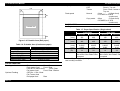
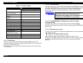
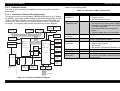
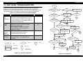
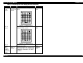
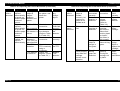
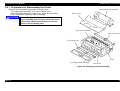
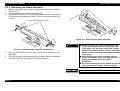
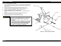
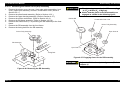
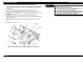
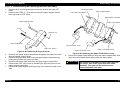
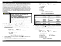
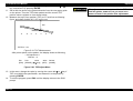
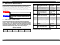
1
EPSON FX-2180 PRODUIT EPSON France S.A. SERVICE MANUAL 6(59,&(0$18$/ 3LQ,PSDFW'RW3ULQWHU EPSON FX-2180 ® 4009047 NOTICE All rights reserved. No part of this manual may be reproduced, stored in a retrieval system, or transmitted in any form or by any means, electronic, mechanical, photocopying, recording, or otherwise, without the prior written permission of SEIKO EPSON CORPORATION. The contents of this manual are subject to change without notice. All effort have been made to ensure the accuracy of the contents of this manual. However, should any errors be deteced, SEIKO EPSON would greatly appreciate being informed of them. The above not withstanding SEIKO EPSON CORPORATION can assume no responsibility for any errors in this manual or the consequences thereof. EPSON is a registered trademark of SEIKO EPSON CORPORATION. General Notice: Other product names used herein are for identification purpose only and may be trademarks or registered trademarks of their respective owners. EPSON disclaims any and all rights in those marks. Copyright © 1996 SEIKO EPSON CORPORATION. Printed in Japan. PRECAUTIONS Precautionary notations throughout the text are categorized relative to 1)Personal injury and 2) damage to equipment. DANGER Signals a precaution which, if ignored, could result in serious or fatal personal injury. Great caution should be exercised in performing procedures preceded by DANGER Headings. WARNING Signals a precaution which, if ignored, could result in damage to equipment. The precautionary measures itemized below should always be observed when performing repair/maintenance procedures. DANGER 1. ALWAYS DISCONNECT THE PRODUCT FROM THE POWER SOURCE AND PERIPHERAL DEVICES PERFORMING ANY MAINTENANCE OR REPAIR PROCEDURES. 2. NOWORK SHOULD BE PERFORMED ON THE UNIT BY PERSONS UNFAMILIER WITH BASIC SAFETY MEASURES AS DICTATED FOR ALL ELECTRONICS TECHNICIANS IN THEIR LINE OF WORK. 3. WHEN PERFORMING TESTING AS DICTATED WITHIN THIS MANUAL, DO NOT CONNECT THE UNIT TO A POWER SOURCE UNTIL INSTRUCTED TO DO SO. WHEN THE POWER SUPPLY CABLE MUST BE CONNECTED, USE EXTREME CAUTION IN WORKING ON POWER SUPPLY AND OTHER ELECTRONIC COMPONENTS. WARNING 1. REPAIRS ON EPSON PRODUCT SHOULD BE PERFORMED ONLY BY AN EPSON CERTIFIED REPAIR TECHNICIAN. 2. MAKE CERTAIN THAT THE SOURCE VOLTAGES IS THE SAME AS THE RATED VOLTAGE, LISTED ON THE SERIAL NUMBER/RATING PLATE. IF THE EPSON PRODUCT HAS A PRIMARY AC RATING DIFFERENT FROM AVAILABLE POWER SOURCE, DO NOT CONNECT IT TO THE POWER SOURCE. 3. ALWAYS VERIFY THAT THE EPSON PRODUCT HAS BEEN DISCONNECTED FROM THE POWER SOURCE BEFORE REMOVING OR REPLACING PRINTED CIRCUIT BOARDS AND/OR INDIVIDUAL CHIPS. 4. IN ORDER TO PROTECT SENSITIVE MICROPROCESSORS AND CIRCUITRY, USE STATIC DISCHARGE EQUIPMENT, SUCH AS ANTI-STATIC WRIST STRAPS, WHEN ACCESSING INTERNAL COMPONENTS. 5. REPLACE MALFUNCTIONING COMPONENTS ONLY WITH THOSE COMPONENTS BY THE MANUFACTURE; INTRODUCTION OF SECONDSOURCE ICs OR OTHER NONAPPROVED COMPONENTS MAY DAMAGE THE PRODUCT AND VOID ANY APPLICABLE EPSON WARRANTY. PREFACE This manual describes basic functions, theory of electrical and mechanical operations, maintenance and repair procedures of FX-2180. The instructions and procedures included herein are intended for the experienced repair technicians, and attention should be given to the precautions on the preceding page. The chapters are organized as follows: CHAPTER 1. PRODUCT DESCRIPTIONS Provides a general overview and specifications of the product. CHAPTER 2. OPERATING PRINCIPLES Describes the theory of electrical and mechanical operations of the product. CHAPTER 3. TROUBLESHOOTING Provides the step-by-step procedures for troubleshooting. CHAPTER 4. DISASSEMBLY AND ASSEMBLY Describes the step-by-step procedures for disassembling and assembling the product. CHAPTER 5. ADJUSTMENTS Provides Epson-approved methods for adjustment. CHAPTER 6. MAINTENANCE Provides preventive maintenance procedures and the lists of Epson-approved lubricants and adhesives required for servicing the product. APPENDIX Provides the following additional information for reference: • Connector pin assignments • Electric circuit boards components layout • Exploded diagram • Electrical circuit boards schematics REVISION STATUS Rev. A Date 1998/04/02 Page(s) All Contents First release TABLE OF CONTENTS PRODUCT DESCRIPTIONS 1.1 SPECIFICATIONS .........................................................................................................................................................1-1 1.2 OPERATION..................................................................................................................................................................1-8 1.2.1 Control Panel Operation.....................................................................................................................................................................1-8 1.2.1.1 Switches ....................................................................................................................................................................................1-8 1.2.1.2 Lamps .......................................................................................................................................................................................1-9 1.2.2 Buzzer ..................................................................................................................................................................................................1-9 1.3 SPECIAL FUNCTION ........................................................................................................... .......................................1-10 1.3.1 Operation at power on......................................................................................................................................................................1-10 1.3.1.1 Self Test ..................................................................................................................................................................................1-10 1.3.1.2 Default Setting.........................................................................................................................................................................1-10 1.3.1.3 Data Dump ..............................................................................................................................................................................1-11 1.3.1.4 Clear EEPROM .......................................................................................................................................................................1-11 1.3.1.5 Clear EEPROM for driving line counter for ribbon changing timing.........................................................................................1-11 1.3.1.6 Alternate copy mode ..............................................................................................................................................................1-11 1.3.1.7 Bi-D Adjustment ......................................................................................................................................................................1-12 1.4 CONSUMABLES & OPTIONS...................................................................................................... ...............................1-12 1.4.1 Consumables ....................................................................................................................................................................................1-12 1.4.2 Options ..............................................................................................................................................................................................1-12 OPERATING PRINCIPLES 2.1 OVERVIEW....................................................................................................................................................................2-1 2.1.1 Printer Mechanism..............................................................................................................................................................................2-1 2.1.2 Power Supply Circuit..........................................................................................................................................................................2-2 2.1.2.1 Power Supply Overview ............................................................................................................................................................2-2 2.1.3 Control Circuit.....................................................................................................................................................................................2-3 2.1.3.1 Overview of Control Circuit Operation .......................................................................................................................................2-3 TROUBLESHOOTING 3.1 OVERVIEW....................................................................................................................................................................3-1 3.2 TROUBLESHOOTING INFORMATION.........................................................................................................................3-1 3.2.1 Printhead .............................................................................................................................................................................................3-1 3.2.2 Detectors .............................................................................................................................................................................................3-2 3.2.3 Motors..................................................................................................................................................................................................3-3 3.2.4 Error Codes with Indications and Buzzer.........................................................................................................................................3-3 3.3 UNIT LEVEL TROUBLESHOOTING ................................................................................................. ............................3-4 3.4 REPAIRING THE POWER SUPPLY BOARD................................................................................................................3-7 3.5 REPAIRING C244 MAIN BOARD ASSEMBLY .............................................................................................................3-9 3.6 REPAIRING THE PRINTER MECHANISM..................................................................................................................3-12 DISASSEMBLY AND ASSEMBLY 4.1 OVERVIEW....................................................................................................................................................................4-1 4.1.1 Precaution ...........................................................................................................................................................................................4-1 4.1.2 Tools ....................................................................................................................................................................................................4-1 4.1.3 Service Check After Repair................................................................................................................................................................4-2 4.1.4 Specifications for Screws ..................................................................................................................................................................4-3 4.2 DISASSEMBLY AND ASSEMBLY ................................................................................................................................4-4 4.2.1 Preparation for Disassembly the Printer ..........................................................................................................................................4-5 4.2.2 Removing the Panel Board Assembly ..............................................................................................................................................4-6 4.2.3 Removing the Printhead.....................................................................................................................................................................4-7 4.2.4 Removing the HP Sensor ...................................................................................................................................................................4-8 4.2.5 Removing the PW Sensor Assembly ................................................................................................................................................4-9 4.2.6 Removing the Platen Assembly.......................................................................................................................................................4-10 4.2.7 Removing the Upper Housing Assembly........................................................................................................................................4-11 4.2.8 Removing the Case Open Sensor Assembly..................................................................................................................................4-12 4.2.9 Removing the Printer Mechanism ...................................................................................................................................................4-13 4.2.9.1 Removing the CR Motor Assembly .........................................................................................................................................4-14 4.2.9.2 Removing the PF Motor ..........................................................................................................................................................4-15 4.2.9.3 Removing the PG Sensor Assembly .......................................................................................................................................4-16 4.2.9.4 Removing the Right Frame Assembly .....................................................................................................................................4-17 4.2.9.5 Disassembling the Right Frame Assembly..............................................................................................................................4-18 4.2.9.6 Removing the Left Frame Assembly .......................................................................................................................................4-20 4.2.9.7 Removing the Ribbon Drive (RD) Assembly ...........................................................................................................................4-21 4.2.9.8 Removing the CR Assembly ...................................................................................................................................................4-22 4.2.9.9 Removing the Rear PE Sensor Assembly...............................................................................................................................4-24 4.2.9.10 Removing the Front PE Sensor Assembly ............................................................................................................................4-24 4.2.9.11 Removing the Main Board Assembly ....................................................................................................................................4-25 4.2.9.12 Removing the Power Supply board Assembly ......................................................................................................................4-26 4.2.10 Disassembly and Assembly of CSF Bin 1.....................................................................................................................................4-27 4.2.10.1 Disassembling the Right Side Block......................................................................................................................................4-27 4.2.10.2 Disassembling Paper Support Block Assembly.....................................................................................................................4-28 4.2.10.3 Removing the Paper Eject Assembly Cover..........................................................................................................................4-30 4.2.11 Disassembly and Assembly of CSF Bin 2.....................................................................................................................................4-31 4.2.11.1 Disassembling the Right Side Block......................................................................................................................................4-31 4.2.11.2 Disassembling the Paper Support Block Assembly...............................................................................................................4-32 ADJUSTMENT 5.1 ADJUSTMENT OVERVIEW...........................................................................................................................................5-1 5.1.1 Required Adjustment..........................................................................................................................................................................5-1 5.1.2 Required Adjustment Tools ...............................................................................................................................................................5-1 5.2 ADJUSTMENT AND RESETTING.................................................................................................................................5-2 5.2.1 Platen Gap Adjustment ......................................................................................................................................................................5-2 5.2.2 Bi-directional Print Alignment (Bi-d) Adjustment.............................................................................................................................5-4 5.2.2.1 Bi-d Adjustment using the Setting Diskette ...............................................................................................................................5-4 5.2.2.2 Bi-D Adjustment from the Control Panel ...................................................................................................................................5-6 5.2.3 Factory Settings..................................................................................................................................................................................5-7 5.2.4 TPE Level Reset..................................................................................................................................................................................5-8 MAINTENANCE 6.1 PREVENTIVE MAINTENANCE .....................................................................................................................................6-1 6.2 APPLYING LUBRICATION ...........................................................................................................................................6-1 APPENDIX 7.1 CONNECTOR SUMMARY.............................................................................................................................................7-1 7.2 CIRCUIT BOARD COMPONENT LAYOUT ...................................................................................................................7-5 7.3 EXPLODED DIAGRAMS ...............................................................................................................................................7-7 7.4 CIRCUIT BOARD DIAGRAMS ....................................................................................................................................7-11 &+$37(5 PRODUCT DESCRIPTIONS FX-2180 Service Manual Product Descriptions 1.1 SPECIFICATIONS RESOLUTION This printer is based on FX-2170. The printing speed and copy ability and etc., are increased than that. So, almost main components of this printer is similar to that. This section describes the specifications of this printer as followings; PRINTING SPECIFICATION Print method Impact dot matrix Number of pin 18 pins Print pin arrangement 9×2 Print pin diameter 0.0114 inch (0.29mm) Color Monochrome Print direction Bi-direction with logical seeking PRINT SPEED & PRINTABLE COLUMN Table 1-2. Resolution Printing mode high speed draft Draft Draft condensed Draft emphasized NLQ Bit image Horizontal density 90 dpi 120 dpi 240 dpi 120 dpi Vertical density 72 dpi 72 dpi 720 dpi 72 dpi Adjacent dot print No No No Yes 240 dpi 60,72,80,90 or 120 dpi 120 or 240 dpi 144 dpi 72 dpi No Yes 72 dpi No Table 1-1. Print Speed & Column Printing mode High speed draft Draft Draft condensed Draft emphasized NLQ Character pitch 10 cpi 10 cpi 12 cpi 15 cpi 17 cpi 20 cpi 10 cpi Printable column 136 136 163 204 233 272 136 Printing speed (cps) Normal Copy 1 Copy 2 506 439 337 380 330 284 455 396 341 380 285 285 325 282 244 380 330 284 190 165 142 10 cpi 136 95 82 71 12 cpi 163 114 99 85 15 cpi 204 94 71 31 When the power supply voltage drops to the lower limit, the printer stops printing and then starts printing remain on that line again more slowly than before. When the head temperature rises to the upper limit, the printer stops printing. When the head temperature falls to the normal level, the printer starts printing again more slowly than before. Copy 1 : when paper thickness level is set 3. Copy 2 : When paper thickness lever is set 4 or more. Rev. A PRINTABLE AREA Cut sheet PW LM RM TM PL Printable Area BM Figure 1-1. Printable Area (Cut sheet) 1-1 FX-2180 Service Manual Product Descriptions Table 1-3. Printable Area (Cut Sheet) Single sheet Multi part Width (PW) Refer to Paper / Media Refer to Paper / Media Length (PL) Refer to Paper / Media Refer to Paper / Media 3mm or more Left margin (LM) 3mm or more (PW≤364mm) (PW≤364mm) 25mm or more 25mm or more (PW=420mm) (PW=420mm) Right margin (RM) 3mm or more 3mm or more (PW≤364mm) (PW≤364mm) 25mm or more 25mm or more (PW=420mm) (PW=420mm) Top margin (TM) 4.2mm or more 4.2mm or more Bottom margin (BM) 4.2mm or more 4.2mm or more Notice : Maximum horizontal printable area is 345.2mm. Envelope Continuous paper PW LM RM TM PL Printable Area BM PW LM RM TM Printa ble Area Figure 1-3. Printable Area (Continuous paper) PL Table 1-5. Printable Area (Continuous paper) BM Figure 1-2. Printable Area (Envelope) Table 1-4. Printable Area (Envelope) Width (PW) Length (PL) Left margin (LM) Right margin (RM) Top margin (TM) Bottom margin (BM) Rev. A Envelope Refer to Paper / Media Refer to Paper / Media 3mm or more 3mm or more 4.2mm or more 4.2mm or more Width (PW) Length (PL) Left margin (LM) Right margin (RM) Top margin (TM) Bottom margin (BM) Envelope Refer to Paper / Media Refer to Paper / Media 3mm or more 3mm or more 4.2mm or more 4.2mm or more 1-2 FX-2180 Service Manual Roll paper Product Descriptions Manual insertion Front / Rear in , Top out CSF Rear in, Top out Tractor Front / Rear / bottom in, Top out Normal 61ms (1/6inch feed) 0.127MPS or 5.0IPS (continuous) Copy mode 83ms (1/6inch feed) 0.078MPS or 3.1IPS (continuous) Paper path PW LM RM Feed speed TM PAPER / MEDIA Single sheet Printable Area Table 1-7. Paper Specification (Single sheet) BM Figure 1-4. Printable Area (Roll paper) Table 1-6. Printable Area (Continuous paper) Width (PW) Length (PL) Left margin (LM) Right margin (RM) Top margin (TM) Bottom margin (BM) PAPER HANDLING Feeding method Optional Feeding Rev. A Envelope Refer to Paper / Media Refer to Paper / Media 3mm or more 3mm or more 4.2mm or more 4.2mm or more Width (inch) (mm) Length (inch) (mm) Thickness (inch) (mm) 2 Weight (g/m ) (lb) Quality Front entry Minimum Maximum 3.9 16.5 100 420 5.8 16.5 148 420 Rear entry Minimum Maximum 3.9 16.5 100 420 3.9 16.5 100 420 0.0025 0.0055 0.0025 0.0055 0.065 0.14 0.065 0.14 52 90 52 90 14 24 14 24 Plain paper, Recycled paper Plain paper, Recycled paper Not curled / Not folded / Not Not curled / Not folded / Not crumpled crumpled Notice : Recycled paper printing is available only under normal temperature and humidity condition. Friction feed Front / Rear Push tractor feed Front / Rear Push & Pull tractor feed Front / Rear Pull tractor feed Front / Rear / Bottom CSF Bin 1 / Bin 2 feed Pull Tractor feed Roll paper feed Rear 1-3 FX-2180 Service Manual Multi part Product Descriptions Table 1-9. Paper Specification (Multi part sheet) Table 1-8. Paper Specification (Multi part sheet) Width (inch) (mm) Length (inch) (mm) Copies Total Thickness (inch) (mm) 2 Weight (g/m ) (lb) Quality Jointing Front entry Minimum Maximum 3.9 16.5 100 420 5.8 16.5 148 420 Original + 5 Rear entry Minimum Maximum 3.9 16.5 100 420 3.9 16.5 100 420 Original + 5 0.0047 0.018 0.012 0.46 40 58 12 15 Plain paper, Recycled paper Not curled / Not folded / Not crumpled Line glue at the top or one side of form 0.0047 0.018 0.012 0.46 40 58 12 15 Plain paper, Recycled paper Not curled / Not folded / Not crumpled Line glue at the top of form Front entry Min. Max. Rear entry Minimum Maximum Envelope Width (inch) 6.5 No. 6 (mm) 165 Length (inch) 3.9 (mm) 92 Envelope Width (inch) 9.5 No. 10 (mm) 241 Length (inch) 4.1 (mm) 105 Total Thickness (inch) 0.0063 0.020 (mm) 0.16 0.52 2 Weight (g/m ) 40 58 (lb) 12 15 Quality BOND paper, Plain paper or AIR MAIL Not curled / Not folded / Not crumpled Notice : Envelope printing is available only under normal temperature and humidity condition. Notice : Envelope should be inserted from rear entrance only. Notice : Envelope setting is landscape direction. Envelope Rev. A 1-4 FX-2180 Service Manual Continuous paper Table 1-10. Paper Specification (Continuous paper) Width Length (inch) (mm) (inch) (mm) Copies Total Thickness (inch) (mm) Weight (Without Multi part) 2 (g/m ) (lb) Weight (one sheet of Multi part) 2 (g/m ) (lb) Quality Continuous paper with labels Table 1-11. Paper Specification (Continuous paper with Labels) Front entry Min. Max. 4 16 101.6 406.4 4 22 101.6 558.8 Original + 5 Rear entry Min. Max. 4 16 101.6 406.4 4 22 101.6 558.8 Original + 5 Bottom entry Min. Max. 4 16 101.6 406.4 4 22 101.6 558.8 Original + 5 0.0025 0.065 0.018 0.046 0.0025 0.065 0.018 0.046 0.0025 0.065 0.018 0.046 52 12 82 22 52 12 82 22 52 12 82 22 40 58 40 58 40 58 12 15 12 15 12 15 Plain paper, Recycled paper, Carbonless multi part paper Jointing Point glue or paper staple (both side) Notice : Original + 6 copies paper is available in pull tractor feed. Rev. A Product Descriptions Label size (inch) (mm) Width (inch) (mm) Length(inch) (mm) Base sheet Thickness (inch) (mm) Total Thickness 2 (g/m ) (lb) Label Weight 2 (g/m ) (lb) Quality Front entry Min. Max. Rear entry Min. Max. Bottom entry Min. Max. 15/16 × 2.5 23.8 × 63.5 15/16 × 2.5 23.8 × 63.5 4 101.6 4 101.6 16 406.4 22 558.8 0.0028 0.07 0.0035 0.09 0.0063 0.16 0.0075 0.19 4 101.6 4 101.6 16 406.4 22 558.8 0.0028 0.07 0.0035 0.09 0.0063 0.16 0.0075 0.19 68 17 68 17 A VERY A VERY CONTINUOUS CONTINUOUS FORM LABEL, A FORM LABEL, A VERY MINI-LINE VERY MINI-LINE LABELS or the LABELS or the same quality labels same quality labels Notice : Original + 6 copies paper is available in pull tractor feed. Notice : The base sheet of label must be continuous paper. Notice : The continuous paper with labels should be inserted from front or bottom entrance. 1-5 FX-2180 Service Manual Roll paper Product Descriptions Table 1-12. Paper Specification (Multi part sheet) Width Length (inch) (mm) (inch) (mm) Thickness Weight Quality INTERFACE Standard Option (inch) (mm) 2 (g/m ) (lb) Front entry Min. Max. Rear entry Minimum Maximum 8.5 216 0.0035 0.0028 0.07 0.09 52 82 14 22 Plain paper Not curled / Not folded / Not crumpled Bi-directional parallel interface (IEEE-1284 nibble mode) Type-B interface level 2 SOFTWARE SPECIFICATION Control code ESC/P IBM 2381 Plus Emulation Fonts 2 LQ & 1 draft Bitmap typefaces 8 Barcode fonts Character table Standard version 11 tables NLSP version 20 tables Input buffer 64 kB ENVIRONMENT CONDITION Temperature 5 - 35°C 15 - 25°C Humidity Rev. A -30 - 60°C 10 - 80%RH 30 - 60%RH (Operation) (Recycled paper, envelope, label or roll paper printing) (Non-operation) (Operation) (Recycled paper, envelope, label or roll paper printing) ELECTRICAL SPECIFICATION 120V version Rated voltage AC120V Input voltage range AC 99 - 132V Rated frequency range 50 - 60Hz Input frequency range 49.5 - 60.5Hz Rated current 1.0A (max. 1.8A) Power consumption Approx. 46W (ISO/IEC10561 Letter pattern) Energy Star program compliant Insulation resistance 10MΩ min. (AC line - Chassis, 500V) Dielectric strength AC1000V rms 1 minute or AC1200V rms 1 second (AC line - Chassis) 230V version Rated voltage AC220 - 240V Input voltage range AC 198 - 264V Rated frequency range 50 - 60Hz Input frequency range 49.5 - 60.5Hz Rated current 0.5A (max. 0.9A) Power consumption Approx. 46W (ISO/IEC10561 Letter pattern) Energy Star program compliant Insulation resistance 10MΩ min. (AC line - Chassis, 500V) Dielectric strength AC1500V rms 1 minute (AC line - Chassis) UPS (Universal Power Supply) version Rated voltage AC100-120V / AC220 - 240V Input voltage range AC90 - 132V / AC 198 - 264V Rated frequency range 50 - 60Hz Input frequency range 49.5 - 60.5Hz Rated current 1.1A (max.1.8A) / 0.5A (max. 0.9A) Power consumption Approx. 46W (ISO/IEC10561 Letter pattern) Energy Star program compliant Insulation resistance 10MΩ min. (AC line - Chassis, 500V) Dielectric strength AC1500V rms 1 minute (AC line - Chassis) 1-6 FX-2180 Service Manual Product Descriptions PHYSICAL SPECIFICATIONS Dimensions 639mm(W) × 402mm(D) × 257mm(H) (with CSF bin1) 639mm(W) × 469mm(D) × 380mm(H) (with CSF bin2) 639mm(W) × 598mm(D) × 411mm(H) Weight Approx. 13kg (with CSF bin1) 16.3kg (with CSF bin2) 17.2kg RELIABILITY Total print volume MTBF Printhead life SAFETY APPROVAL 120V version Safety standard EMI 230V version Safety standard EMI UPS version Safety standard EMI 7.5 million lines (except printhead) 10000POH Approx. 300 million characters UL1950 CSA C22.2 No.950 FCC part 15 subpart B class B CSA C108.8 class B CE MARKING 230V version & UPS version Low Voltage Directive 73/23/EEC EN60950 EMC Directive 89/336/EEC EN55022 class B EN61000-3-2 EN61000-3-3 EN50082-1 IEC801-2 IEC801-3 IEC801-4 ACOUSTIC NOISE Level Approx. 55 dB(A) (ISO 7779 pattern) INK RIBBON CARTRIDGE Type Fabric Color Black Ribbon life Approx. 12 million characters (Draft 10cpi, 14 dot/characters) EN60950 (TÜV, NEMKO) EN55022(CISPR pub.22) class B AS/NZS 3548 class B UL1950 CSA C22.2 No.950 EN60950 (TÜV, NEMKO) FCC part 15 subpart B class B CSA C108.8 class B EN55022(CISPR pub.22) class B AS/NZS 3548 class B Figure 1-5. Exterior View of the FX-2180 Rev. A 1-7 FX-2180 Service Manual Product Descriptions 1.2.1.1 Switches 1.2 OPERATION This section describes user operation. 1.2.1 Control Panel Operation WARNING As this operate switch is secondary switch, the This printer’s operation panel contains seven switches and nine LED lamps, as shown below; Font Pitch Tear Off/Bin LF/FF Draft Roman Sans Serif 10 cpi 12 cpi 15 cpi 17 cpi 20 cpi PS Tear Off Bin 1 Bin2 Card 3 sec Load/Eject LED Off LED On LED Blinks Figure 1-6. Control Panel primary circuit of power supply circuit is hot condition when the power cable is connected in AC line. Paper Out Pause Micro Adjust Operate Rev. A Operate This switch turns the printer on / off. It is set in the secondary circuit of the power supply board. Pause This switch alternates the printer activity between on line and off line. Hold it down over 3 seconds when the printer is in stand-by condition, and the Micro Adjust functions is enabled. If the switch is pressed again, this function is disabled. Load / Eject Pressing it loads cut sheet or continuous paper when the printer is out of paper. Pressing it eject cut sheet to the stacker or continuous paper to the paper park. LF / FF Pressing it shortly executes line feed. Holding it down for a few seconds executes form feed when continuous paper is used, or eject cut sheet to the stacker when cut sheet is used. Tear Off When continuous paper is used, pressing it moves a page to the tear off position. And pressing it again moves to the next page TOF position. Bin * This switch selects CSF bin number or the Card mode when cut sheet is used. “*”: Card mode is for post card or envelope using. Font This switch selects one font of Draft, Roman and Sans serif. Pitch This switch selects one pitch of 10cpi, 12cpi, 15cpi, 20cpi and Proportional Spacing. 1-8 FX-2180 Service Manual Micro Adjust ↑ / ↓ These switches are effective when the micro adjust function is enable by Pause switch. Micro Adjust function executes micro feed backward or forward by 1/216 inch. TOF adjustment is enable in the TOF position after loading, and Tearoff adjustment is enable in the Tear-off position. 1.2.1.2 Lamps Pause (Orange) It is on when the printer is in pause, and it is off when the printer is on line condition. It blinks when the Micro Adjust function is enabled or printhead is in hot condition. Paper Out (Red) It is on when the printer is in the paper out condition, and it is off when the paper is set in the printer. Tear Off / Bin (Green) Only right LED is on when CSF bin1 is selected. Only left LED is on when CSF bin 2 is selected. Both LEDs are on when Card mode is selected. Both LEDs blink when continuous paper is in the Tear-Off position. Both LEDs are off when continuous paper is out of the Tear-Off position. Font (Green) The font LEDs consist of two LEDs. The current using font is shown by these two LEDs on/ off combinations. Pitch (Green) The pitch LEDs consist of three LEDs. The current using pitch is shown by these three LEDs on/ off combinations. Rev. A Product Descriptions 1.2.2 Buzzer This printer makes buzzer sounds when it discover error or illegal condition, as listed below: Paper Out error Approx.100ms buzzer sounds three times with two intervals of approx.100ms. Cover open error Approx.100ms buzzer sounds three times with two intervals of approx.100ms. Release lever operation error Approx.100ms buzzer sounds five times and approx.100ms interval is four times. Illegal panel operation One approx.100ms buzzer sounds. 1-9 FX-2180 Service Manual 1.3 SPECIAL FUNCTION This printer provides the special functions to extend the printer abilities for customers as followings, 1.3.1 Operation at power on Product Descriptions START Holding down Pitch switch, turn on. Pitch switch selects Main menu. Language menu This function is executed when one or more switches are holding down and power on continue at same time. Then, the printer performs special function. 1.3.1.1 Self Test This function is useful to check the printing function on itself. LNQ Self Test Turning on the printer while holding down Load / Eject switch, the printer prints self test pattern with NLQ fonts. If desire to stop it, turn off the printer once. Draft Self Test Turning on the printer while holding down FF / LF switch, the printer prints self test pattern with NLQ fonts. If desire to stop it, turn off the printer once. 1.3.1.2 Default Setting Several printer settings loaded at power-on can be changed in this operation. Setting Method The setting method is shown in the flowchart as following, If change language, press Pitch switch NO Tear-off / Bin switch change submenu indication. YES Tear-off/ Bin, Pause LED indicates submenu. Press Pitch switch. Press Font switch Tear-off / Bin switch change submenu. Setting sheet is printed by the language. Finish setting? NO YES Pitch LED indicates Main Menu. Power off the pprinter once. END Figure 1-7. Default Setting Flowchart Rev. A 1-10 FX-2180 Service Manual Setting menu Product Descriptions 1.3.1.4 Clear EEPROM Table 1-13. Factory setting Item Character Table International character set for Italic table Page length for front tractor Page length for rear tractor High Speed Draft Print direction Software I/F mode Auto I/F Wait Time Input Buffer Skip Over Perforation Auto Tear off Auto Line Feed Auto CR Return (IBM 2381 Plus only) 0 Slash Buzzer IBM Character Table Factory Setting Value Standard version: PC437 NLSP version: PC437 Italic U.S.A Turning on the printer while holding down Font and Tear off/ Bin switches, The data of EEPROM Area 1 are reset to the factory setting without driving line count, driving hour, driving line counter for ribbon changing timing, starting year, starting month and starting date. (Refer to the FX-2180 Specifications.) CAUTION This printer always stores driving line count, 11inch 11inch On Bi-D ESC/P Auto 10sec. On Off Off Off Off Off On Table 2 1.3.1.3 Data Dump driving hour, driving line counter for ribbon changing timing, starting year, starting month and starting date in EEPROM on the main board 1.3.1.5 Clear EEPROM for driving line counter for ribbon changing timing Turning on the printer while holding down LF / FF and Tear off/ Bin switches, The driving line counter for ribbon changing timing of EEPROM is reset to zero. 1.3.1.6 Alternate copy mode Turning on the printer while holding down Font switch, the printer alternates copy mode on or off. When “off” is selected, beeps one time. When “on” is selected, beeps two times. When the printer gets into copy mode in pull tractor feed, normal temperature and paper thickness lever position 4 or more, it prints draft and bit image with double strike printing. But it may not become two pass printing Turning on the printer while holding down Load / Eject and LF / FF switches, the printer starts Hex. Data printing. desire to return normal print mode, turn off the printer once. This mode is useful to check data translation between the printer and the host computer. Rev. A 1-11 FX-2180 Service Manual Product Descriptions 1.3.1.7 Bi-D Adjustment 1.4 CONSUMABLES & OPTIONS Using this function, the customer can performs Bi-directional adjustment easily. Adjusting Method The setting method is shown in the flowchart as following, 1.4.1 Consumables Ribbon cartridge Ribbon pack S015086 S010033 1.4.2 Options START Pressing Pause switch, turn on Guidance and 1st alignment pattern printing Next alignment pattern printing NO NLQ Bi-D adjustment finish? YES Pitch LED indicates Bi-D setting value Turn off the printer. High capacity cut sheet feeder (bin 1) Second bin cut sheet feeder Pull tractor unit Roll paper holder Serial I/F card 32KB intelligent serial I/F card 32KB intelligent parallel I/F card Local Talk I/F card 32KB IEEE-488 I/F card Coax I/F card Twinax I/F card IEEE-1284 parallel I/F card Ethernet I/F card C80673* C80674* C80032* #8310 C82305* / C82306* C82307* / C82308* C82310* / C82311* C82312* C82313* C82314* C82315* C82345* C82357* END Change Bi-d setting value by LF /LF or Load/ Eject switches. Press Font switch to fix the value. Figure 1-8. Bi-D Adjustment Method CAUTION Bi-D adjust value is not reset by clearing EEPROM. Rev. A 1-12 &+$37(5 OPERATING PRINCIPLES FX-2180 Service Manual Operating Principles 2.1 OVERVIEW Rear Tractor This printer consists of the printer mechanism, the power supply circuit, the control circuit, operation panel, housing and etc,. The operating principles of main components are described in this chapter as followings; Disengage Gear 1 PF Motor 2.1.1 Printer Mechanism The printer mechanism of this printer consists of following several unit; Printhead The printhead prints the dots on the paper via ink ribbon by printing data from the control circuit. Carriage mechanism This mechanism consists of carriage unit, carriage motor (CR Motor), timing belt, driven pulley, CR guide shaft and etc. The carriage unit carries the printhead and move along the CR guide shaft between left end and right end of the printable area by this mechanism. Platen gap mechanism The platen gap (the gap between platen and printhead) are adjusted to make good print quality between different thickness paper. This mechanism consists of CR guide shaft, PG adjust bushing which eccentric with CR guide shaft center, and PG adjust lever. It makes the printhead associate with platen or keep away from platen causing from PG adjust lever position. Paper feed mechanism This mechanism consists of paper feed motor (PF Motor), rear / front tractors, platen, and etc. This mechanism picks up the cut sheet paper , feed the cut sheet paper, or continuous paper to the printhead to print paper by PF Motor. And, printed paper feeds out from the printer. Disengage mechanism This mechanism consists of two disengage gears. It switches the paper feed torque from PF motor to the tractors or paper feed rollers according to paper feeding methods (ex. friction feeding, front push tractor feeding, rear tractor feeding, pull tractor feeding, push-pull tractor feeding). Ribbon advance mechanism This mechanism consists of ribbon feed roller, Driven pulley and etc. This mechanism winds up ink ribbon for one way and make new ribbon surface to appear for printing by carriage motion. Platen PG Adjust Bushing CR Guide Shaft Printhead Carriage Unit Timing Belt CR Motor Driven Pulley Ribbon Feed Roller Disengage Gear 2 Ink Ribbon Front Tractor Figure 2-1. Printer Mechanism Rev. A 2-1 FX-2180 Service Manual 2.1.2 Power Supply Circuit This printer can be powered between three power supply boards: the C166PSB(120V), C166PSE(220-240V) and C244PSH(120V/220-240V). The function of these boards s the same, except for a different in a primary circuit. The input voltages and fuse ratings for these boards are shown below; Operating Principles circuit composed of an ZC-RCC (zero cross ringing choke converter), it realizes to the circuit high stability, efficiency and portability. This circuit provides the power switch (operate switch) in the secondary circuit system. The operate switch on the operation panel controls the power supply circuit. There is +35v line constant voltage control circuit and over current / voltage circuits in order to protect the printer and control circuit. Table 2-1. Power Supply Board Board C166PSB C166PSE C244PSH Input Voltage 103.5 - 132V 198 - 264V 85 - 138V / 187 - 276V The power supply board has two DC power outputs for control circuit and printer mechanism. These power outputs are listed on following table; Table 2-2. Power Supply Outputs Applications Applications • Control Circuit board Logic • Detectors • Operation Panel LEDs +35VDC • CR Motor • PF Motor • Printhead The block diagram of power supply circuit is shown following figure. When AC power enters the printer from external power source, the filter circuit removes the noise. Then AC voltage undergoes full-wave rectification and smoothed to produce direct voltage. But, in case of C244PSH board, the AC voltages undergoes the voltage doubler rectification automatic switching IC and smoothed to produce direct voltage. The voltage is fed to the gate port for the switching FET (Q1)through resistors (R18 and R31), and then the switching circuit operates. The secondary smoothing circuit produces a stepped down +35VDC voltage. The +5VDC is generated and stabled by feeding the +35VDC voltage through the +5VDC power supply circuit IC. As this power supply Rev. A S e c o n d a r y C ir c u it Fuse F1 Rating 3.15A / 125V T2.0AH / 250V 5HT4 2.1.2.1 Power Supply Overview Output Voltage +5VDC P r im a r y C ir c u it + 5 V S w itc h in g R e g u la to r + 5 V D C + 5 V C o n s ta n t V o lta g e C o n tr o l C ir c u it + 5 V O v e r c u rre n t P r o te c tio n C ir c u it A C in p u t F ilte r C ir c u it F u ll W a v e R e c tific a tio n C ir c u it C 2 4 4 P S H o n ly V o lta g e D o u b le r R e c tific a tio n A u to - s w itc h in g C ir c u it S m o o th in g C ir c u it S w itc h in g C ir c u it + 3 5 V D C S m o o th in g C ir c u it P h o to C o u p le r + 3 5 V L in e O v e r L o a d D e te c to r C ir c u it C P U P o rt 2 0 + 3 5 V L in e C o n s ta n t V o lta g e C o n tr o l C ir c u it P h o to C o u p le r + 3 5 V L in e O v e r V o lta g e P r o te c tio n C ir c u it + 5 V L in e O v e r V o lta g e P r o te c tio n C ir c u it + 3 5 V L in e O v e r C u rre n t P r o te c tio n C ir c u it O p e r a tio n S W Figure 2-2. Power Supply Circuit Block Diagram 2-2 FX-2180 Service Manual Operating Principles The functions of main components of control circuit on C244MAIN board are shown on the following table. 2.1.3 Control Circuit The control circuit consists of C244MAIN control board and the operation panel board. 2.1.3.1 Overview of Control Circuit Operation This printer’s control circuit includes a TMP96C141BF that ran at 17.20MHz, an E05B50** gate array, a 2Mbit PROM (or 2M / 4Mbit Flash-ROM), a 1Mbit / 4Mbit PS-RAM (or SRAM), a serial EEPROM (or parallel EEPROM) and other circuits. This control circuit oversees control of all the components in the printer. The following chart shows the control circuit block diagram. Q 2 ~ Q 1 9 H e a d D rv . IC 5 T y p e B I/F IC 3 E P R O M P E -R e a r D e te c to r IC 1 G a te A rra y O p e ra te S W E 0 5 B 5 0 ** P E -F ro n t D e te c to r IC 2 IC 8 S e r ia l E E P R O M C P U T M P 9 6 C 1 4 1 B F IC 1 5 R e s t IC P S C T O P D e te c to r H o m e D e te c to r R e le a s e L e v e r D e te c to r P W D N 5 V G L 3 5 V G P P o w e r S u p p ly B o a rd Location IC1 CPU (TMP96C141BF) IC2 1 / 4Mbit PS-RAM 2Mbit PROM IC3 P S -R A M o r S R A M P a r a lle l I/F / L E D s IC Gate array (E05B50**) H e a d T e m p . D e te c to r + 3 5 V V o lta g e D e te c to r P a n e l S W Table 2-3. Functions of Main Components IC5 Serial EEPROM (AT93C46) IC8 SLA7024M A2917SEB Reset IC (BH6150F) IC9 IC12 IC15 Function Control the functions below; • System control • Peripheral device control • Receives data from the host computer and send it to the input buffer in RAM. • Extend the input data held in the buffer to create Image data. • Load image data to the image data buffer. • Transfer image data to the printhead. Buffer and working area The ROM contains the program that runs the CPU and character tables. Contains following data; • Default setting values • Market data • Mechanism & printhead parameter, etc CR motor drive IC PF motor drive IC This IC generates the reset signal at power on or down, and makes reset the CPU and the gate array. G a p L e v e r D e te c to r IC 1 2 P F D rv . U D N 2 9 1 7 E B IC 9 C R D rv . S L A 7 0 2 4 M C S F D rv . C S F D e te c to r : D a ta B u s : A d d re s s B u s Figure 2-3. Control circuit Block Diagram Rev. A 2-3 &+$37(5 TROUBLESHOOTING FX-2180 Service Manual Troubleshooting 3.1 OVERVIEW This chapter contains flowcharts and check point tables that are helpful for troubleshooting the printer. The flowcharts facilitate identifying faulty units or parts from abnormal symptoms. The checkpoints provides unit characteristics, such as resistance, continuity, and so on, to which you can refer when isolating faulty units or parts. R 3 X 15 C5 2 C6 5 16 11 C7 17 C8 X 14 4 8 3.2 TROUBLESHOOTING INFORMATION F R This section describes troubleshooting information to let you find the point of replaceable unit or part. F X 1 9 13 7 C1 X 18 C2 12 C3 C4 X 6 10 T T X 3.2.1 Printhead It is easy to check if a printhead is defective or not. Referring to the following table and figure, measure the printhead coil resistance and check if it is correct Table 3-1. Printhead coil Resistance Test Points Common Pin No Test Pin No. Test Method (Set meter to ohms. Disconnect the printhead after the printer is powered off.) Meter Reading Rev. A Refer to the following figure. Refer to the following figure. Place one lead on each pin and the other lead on each common pin. F COM. C1 Pin No, 1, 7, 13 R C2 C3 C4 9 10, 18 6, 12 COM. C5 Pin No, 2, 5, 11 C6 C7 C8 3, 15 16, 17 4, 8, 14 T : Thermistor terminal X : Not used Figure 3-1. Printhead Connenctor Pin Alignment ± 1.64 Ω (at 25°C) 3-1 FX-2180 Service Manual Troubleshooting 3.2.2 Detectors Table 3-3. Detector Test Point (continue.) Table 3-2. Detector Test Point Detector CN No. CN4 (HP Detector) CN5 (Rear PE Detector) CN6 (Front PE Detector) CN7 (TOP Detector) Rev. A Test Pin No. 1 : HP 2 : GND 3 : +5V 1 : +5V 2 : PE 3 : GND 1 : PE 2 : GND 1:E 2 : GND 3 : +5V 4:A Test Method (Set Meter to DC Voltage) Place one lead on pin 1 and the other lead on pin 2, and check the voltage while blocking two detector terminal. • • Place one lead on pin 2 and the other lead on pin 3, and check the voltage while toggling the detector lever. • Place one lead on pin 1 and the other lead on pin 2, and check the voltage while toggling the detector lever. • Place one lead on pin 1 and the other lead on pin 2, and check the voltage while inserting and removing paper between the detector. • • • • Meter Reading Open : +5V (Home position) Short : 0V (Out of home) Open : +5V (Paper loaded) Short : 0V (No paper) Open : +5V (Paper loaded) Short : 0V (No paper) Open : 0V (No paper) Short : +5V (Paper loaded) Detector CN No. CN12 (Release Detector 1 / 2) 1 : Release 1 2 : GND 3 : Release 2 4 : GND CN13 (PG Detector 1/ 2) 1 : PG1 2 : GND 3 : PG2 4 : GND CN2 on Panel board (Case Open Detector) 1 : COPEN 2 : GND Test Pin No. Test Method (Set Meter to DC Voltage) Place one lead on pin 1 and the other lead on pin 2, and check the voltage while toggling the release lever. Place one lead on pin 3 and the other lead on pin 4, and check the voltage while toggling the release lever. Place one lead on pin 1 and the other lead on pin 2, and check the voltage while toggling the PG detector lever. Place one lead on pin 2 and the other lead on pin 3, and check the voltage while toggling the detector lever. Meter Reading • Open : +5V • Short : 0V • Open : +5V • Short : 0V • Open : +5V (Case opened) • Short : 0V (Case closed) 3-2 FX-2180 Service Manual Troubleshooting 3.2.3 Motors 3.2.4 Error Codes with Indications and Buzzer Table 3-4. Motor Test Point PF Motor Motor connector No. Com-mon Pin No. Test Pin No Test Method (Set meter to horms. Disconnect the motor from control board after the printer is powered off.) Meter Reading CR Motor Motor connector No. Com-mon Pin No. Test Pin No Test Method (Same as for the PF Motor) Meter Reading Rev. A CN10 1,2,3,4 Place one lead on pin 1 and the other lead on pin 3. Place one lead on pin 2 and the other lead on pin 4. 16.1 Ω ± 10% (per phase, at 25°C) CN11 5 1,2,3,4 Place one lead on pin 5 and the other lead on each of 4 pins. Table 3-5. Error Codes with Indications and Buzzer Indicators Error Paper Tear Buzzer* Pause Pitch Font Condition Out Off/Bin Paper out On On ❍×3 On Blinks Paper jam ❍×3 (Paper ejected incompletely) Head hot Blinks Case open On ❍×3 Fatal error Blinks Blinks Blinks Blinks Blinks ●×5 * : ❍ Indicates that the beep sounds for 100ms with an interval of 100ms. ● Indicates that the beep sounds for 500ms with an interval of 100ms. 2.7 Ω ± 10% (per phase, at 25°C) 3-3 FX-2180 Service Manual Troubleshooting 1. Abnormal CR Operation 3.3 UNIT LEVEL TROUBLESHOOTING START You may be able to identify the defective unit just from the symptom displayed. The table below provides the symptoms for a number of failures. Once you identify the problem, refer to the flowchart listed in the right-hand column of the table to determine the cause of the problem. Table 3-6. Symptoms and Problem Descriptions Symptom Abnormal CR Operation Abnormal Paper Feed Abnormal Control Panel Operation Abnormal Printing Problem Description • Carriage dose not move at all. • When the printer is powered on, the CR moves away from home position after a moment and stops. All indicator LEDs on the control panel blinks. • Paper is not fed at all. • When the printer is power on, paper ejected automatically. • when paper is loaded, it is ejected automatically and then the printer indicates “Ready”. • Control panel indicator LEDs do not light. • Operate switch does not work. • Panel switches do not work. Start Decision Is CN11 connected correctly? NO NO Connect CN11 correctly. YES YES Dose the CR motor stop during or after initialization? NO Check the motor coil resistance. Refer to Table3-4. Is the problem solved? NO YES YES END Is it OK? Dose the CR motor move freely by hand when power off? YES NO Replace the C244MAIN board. Replace the CR motor. NO Flowchart 2-1, 2-2 YES END Is the Platen gap adjusted properly? NO Adjust Gap properly. Refer to Chapter5. YES Flowchart 3 Is CN4 connected correctly? NO YES Replace the oil pad on the carriage unit. clean the CR shaft, and lubricate the oil pad and surface of the shaft. Is the problem solved? YES NO END A Connect CN4 correctly. • No image is printed. • Faulty printing - some dots are not printing. The repair procedure flowcharts use the following symbols: START Flowchart No. Flowchart 1 Dose the CR motor rotates when printer is power on? END Flowchart 4 NO Is the problem solved? Is resistance of CR motor correctly? Refer to Table 5-4. YES NO END END END Dose HP Detector work correctly? Refer to Table3-2. Replace CR motor. YES NO Replace HP detector. NO YES Processing Branching NO Forwarding to another item Return to the strat of the item Is the problem solved? YES Replace the C244MAIN board. Is the problem solved? YES A END END Figure 3-2. Flowchart Symbols Rev. A Figure 3-3. Flowchart 1 3-4 FX-2180 Service Manual 2. Abnormal Paper Feed Operation - 1 Troubleshooting 2. Abnormal Paper Feed Operation - 2 START START Dose PF motor rotate? Is CN10 connected correctly? NO YES NO Connect CN10 correctly. YES NO Is paper ejected automatically when power on? NO Is the problem solved? Flowchart 2-2 Is the resistance of the PF motor coils correctly? Is CN7 connected correctly? NO Replace PF motor. Is the problem solved? NO Remove the substance caught in YES detector. NO NO Is the problem solved? YES Replace the detector. NO Is the problem solved? END Replace the C244MAIN board. YES NO Is the problem solved? Are CN5 and CN6 connected correctly? Dose the Front detector work correctly? Dose the TOP detector work correctly? Is the problem solved? Replace the detector. NO END YES END YES Dose the release detector work correctly? YES NO Replace the detector. YES NO END NO YES NO Is the problem solved? NO END Replace the cable. Is the NO problem solved? YES YES NO Is the problem solved? NO Connect them correctly. YES YES YES NO YES NO Connect CN12 correctly. NO END Is FFC cable OK? NO Is anything jammed between the Front / Rear PE and platen? Is CN12 connected correctly? YES YES Clear the jam? NO Connect CN7 correctly. END Dose the printer indicate "Paper Out",after paper is ejected? Dose the detector work correctly? NO YES NO YES YES YES YES Replace the C244MAIN board. Is anything stuck on TOP Detector? NO YES END YES Is cut sheet loaded correctly, but continuous paper not loaded at all? YES YES Dose the printer indicate "Ready",after paper is ejected? Is paper ejected automatically after loading? Replace the detector. Replace the C244MAIN board. Is the problem solved? END Is the problem solved? YES END YES Is the problem solved? NO Replace the C244MAIN board. END YES END END Figure 3-4. Flowchart 2 - 1 Rev. A Replace the C244MAIN board. END Figure 3-5. Flowchart 2 - 2 3-5 FX-2180 Service Manual 3. Abnormal Control Panel Operation Troubleshooting 4. Abnormal Printing START START Dose the operate button turn on or off? Is the self-test printed correctly? Check the Operation button on the operation panel using a multimeter. NO Check the data from host PC using Hex dump function. YES NO YES Is CN7 connected correctly? NO Check them on the operation panel using a multimeter. Is Operate button correctly? NO Replace PNL board. Are all dots printed correctly? NO Is the problem solved? Is the problem solved? Are all LEDs blinking? Is the problem solved? Check the printhead driver, motor drivers and power supply board. END YES Is Operate Panel FFC connected correctly? NO Connected the cable correctly. YES END NO YES YES NO Is Operate Panel FFC connected correctly? NO Connected the cable correctly. NO Is the problem solved? Is the problem solved? NO YES Check the FFC using a multimeter. YES Check pin 19 of the FFC. END Is the FFC OK? END Is FFC OK? NO Replace the FFC. YES NO Replace the C244MAIN board. Is the problem solved? YES Erplace the FFC. YES NO NO Is the problem solved? Replace the C166PSB/PSE/PSH board. END Is the problem solved? Is the printhead OK? NO Are the correct printer driver installed? NO Replace the.printhead. NO YES END YES NO NO NO Is the problem solved? YES The cable has a problem. END END YES END Reinstall the ribbon mask. NO END YES Replace the C244MAIN board. YES Is the problem solved? Is the problem solved? END Replace the FFC. Replace the power supply board. YES YES NO NO Replace the C244MAIN board. Replace the FFC. Is the bottom of charactor missing YES END END Is the FFC OK? END Install the correct printer drivers. Dose the printer work correctly with another pritnner cable? YES Is the problem NO solved? Connect the FFC correctly. Check the FFC using a multimeter. END NO Is the problem NO solved? Is the problem solved? NO YES YES Is the problem YES solved? YES Is the FFC OK? Is head FFC connected correctly? Reset the settings to default. NO YES Check the FFC using a multimeter. YES NO YES Check printhead coil resistance.(Refer to Table 3-1.) Replace PNL board. NO Are the printer setting correctly? YES YES YES Is any dot missing? NO YES END END END END END Figure 3-6. Flowchart 3 Rev. A Figure 3-7. Flowchart 4 3-6 FX-2180 Service Manual Troubleshooting 3.4 REPAIRING THE POWER SUPPLY BOARD This section provides instructions for repairing a defective power supply board assembly. It describes various symptoms, likely causes and checkpoints. Refer to proper waveforms, resistance and other values shown in the tables when evaluating the operation of any potentially faulty component. Check these value and take the appropriate action. WARNING The OPERATE switch on the operation panel only turns the secondary power circuit on or off, so the primary circuit is live as long as the printer is connected to AC power outlet. Before, you repair or touch the power supply board, be sure to disconnect the AC power outlet. CAUTION This information is necessary only for servicers who repair to the component level. Servicers who repair to the unit level (including all servicers in the U.S.) can ignore this section. Table 3-8. Repairing the Power Supply Board (Continued.) Problem +35V and +5V lines are not output when the printer is power on. Cause Switching FET Q1 is failure. Checkpoint • Check the resistance between SOURCE and DRAIN is infinite. • Check the voltage waveform between SOURCE and DRAIN of Q1. Solution Replace Q1. PC1 is failure. Figure 3-8. Waveform 1 Check the waveform between pin 3 and 4. Replace PC1. Q32 is failure. Q31 is failure. Figure 3-9. Waveform 2 Check that the resistance between COLLECTOR and EMITTER is infinite. Check that resistance between SOURCE and DRAIN is infinite. Replace Q32. Replace Q31. Table 3-7. Repairing the Power Supply Board Problem +35V and +5V lines are not output when the printer is power on. Cause The diode bridge DB1 is failure. The transformer T1 coil is open. Rev. A Checkpoint Measure the DC voltage between the pin 3 and 4 of DB1. Measure the resistance of T1 coils at pin 12 - 15, 9 - 11, 7 - 8 or 3 - 4. Solution Replace DB1. Replace T1. 3-7 FX-2180 Service Manual Troubleshooting Table 3-9. Repairing the Power Supply Board (Continued.) Problem +5V lines is not output. Cause Chopper IC IC51 is failure. Q51 is failure. L51 is failure. The PWDN signal is constantly HIGH. Rev. A IC51 is failure. Checkpoint Check the waveform at pin 8 of IC51. Solution Replace IC51. Figure 3-10. Waveform 3 Check the waveform at COLLECTOR of Q51. Replace Q51. Figure 3-11. Waveform 4 Check the resistance between terminals of L51. Check whether the voltage of pin 6 is more than 1.3V or not. If the voltage is more than 1.3V, IC51 is failure. Replace L51. Replace IC51. 3-8 FX-2180 Service Manual Troubleshooting 3.5 REPAIRING C244 MAIN BOARD ASSEMBLY This section provides instructions for repairing C244 MAIN board assembly. It describes various problem, symptoms, likely cases and solutions. The check points columns provide proper waveforms, resistance values and other information for each component of C244 MAIN. CAUTION This information is necessary only for servicers Table 3-11. Repairing C244 MAIN Board Assembly (Continued.) Problem The printer dose not operate at all. Cause The PROM (IC5) is not selected. Checkpoint Check the signal for a change in HIGH and LOW at pin 137 of IC1. Solution Replace the main board. who repair to the component level. Servicers who repair to the unit level (including all servicers in the U.S.) can ignore this section. Table 3-10. Repairing C244 MAIN Board Assembly Problem The printer dose not operate at all. Cause Reset IC15 is defective. Checkpoint Check the voltage waveforms of the VCC signal (CH1 : IC15 pin 7) and /RESET signal (CH2 : IC15 pin 5) when the printer is turned on. CH 1 Solution Replace the main board or IC15. The PSRAM (IC3) is not selected. CPU (IC2) is defective. Figure 3-13. Waveform 6 Check the signal for a change in HIGH and LOW at pin 132 of IC1. Replace the main board. Check the oscillator signal at pins 26 or 27 of the CPU Replace the main board. CH 2 Figure 3-12. Waveform 5 Figure 3-14. Waveform 6 Rev. A 3-9 FX-2180 Service Manual Troubleshooting Table 3-12. Repairing C244 MAIN Board Assembly (Continued.) Problem The carriage operation is abnormal. Cause CPU or IC9 is defective. Checkpoint • Check the input signal waveforms (CH 1) at pins 5, 6, 16 and 17 of IC9. • Check the output signal waveforms (CH 2) at pins 1, 8, 11 and 18 of IC9. CH 1 Solution • If the input signal is not correct, replace the main board. • If the output signal is not correct, replace IC9 or replace the main board. Table 3-13. Repairing C244 MAIN Board Assembly (Continued.) Problem Paper feed is abnormal. Cause IC1, IC2 or IC12 is defective. Checkpoint • Check the input signal waveforms (CH 1) at pins 26 and 43 of IC12. • Check the output signal waveforms (CH 2) at pins 3, 6, 18 and 21 of IC12. CH 1 Solution • If the input signal is not correct, replace the main board. • If the output signal is not correct, replace IC12 or replace the main board. CH 2 CH 2 IC1 is defective Figure 3-15. Waveform 7 Check the output signals at pins 62, 63, 64 and 65 of the IC1. If the output signal is not correct, replace the main board. No data is printed. CPU is defective. Figure 3-16. Waveform 7 Check the output signal waveforms at pins 15 or 19 of IC2. If the output signal is not correct, replace the main board. Figure 3-17. Waveform 8 Rev. A 3-10 FX-2180 Service Manual Troubleshooting Table 3-14. Repairing C244 MAIN Board Assembly (Continued.) Problem A particular dot fails to print. Cause IC1 or head drive transistor (Q2 ∼ Q19) is defective. Checkpoint • Check the input signal waveform (CH 1) at BASE of each transistor. • Check the output signal waveform (CH 2) at COLLECTOR of each transistor. CH 1 Solution • If the input signal is not correct, replace the main board. • If the output signal is not correct, replace the transistor or the main board. CH 2 Figure 3-18. Waveform 9 Rev. A 3-11 FX-2180 Service Manual Troubleshooting 3.6 REPAIRING THE PRINTER MECHANISM This section provides instructions for repairing the printer mechanism. It describes various symptoms, likely causes, checkpoints and solutions. The checkpoint columns show items to be checked, including proper values to be set for each component of the printer mechanism. For replacement and adjustment instructions, see Chapter 4 Disassembly and Assembly, and Chapter 5 Adjustment. If the same symptom appears after repair, select another item in the list of the causes and repair the printer according to the instructions. Table 3-16. Repairing the Printer Mechanism (Continued.) Problem CR operation is abnormal. Symptom CR unit moves slightly and then stops. Cause Lack of lubrication or foreign object lodged in the printer. Checkpoint − Move the CR unit manually to check if it moves smoothly − Check CR shaft or oil pad for their condition; dried up or not. HP detector is detective. Check HP detector. (Refer to Table 3-2.) Check the Hp detector. Table 3-15. Repairing the Printer Mechanism Problem CR operation is abnormal. Rev. A Symptom CR motor dose not rotate at all when the printer is turned on. Cause CR motor is defective. CR motor dose not rotate at all and LEDs blink when the printer is turned on. CR motor rotates when the printer is turned on. But the CR unit dose not move. CR unit moves slightly and then stops. CN11 is disconnected from the main board. Checkpoint Measure the coil resistance of the motor: Approx. 2.7Ω (Refer to Table 3-1.) Check CN11. The timing belt comes off from the pinion of CR motor. Check the timing belt. Platen gap is too narrow. Check CR unit by moving it smoothly by hand. Solution Replace CR motor. Connect CN11 correctly. Replace the timing belt. Confirm the platen gap. Adjust platen gap if narrow. CR motor moves left (HP side) and strikes the frame in the printer. A foreign object is lodged in HP detector. CN4 is disconnected from Hp detector. HP detector is failure. Check the connection. Check HP detector. (Refer to Table 3-2.) Solution Replace the oil pad or lubricate CR shaft. Remove it and clean the shaft, and lubricate it. Replace HP detector. Remove any foreign object. Connect CN4 correctly. Replace HP detector. 3-12 FX-2180 Service Manual Troubleshooting Table 3-17. Repairing the Printer Mechanism (Continued.) Problem Printer is abnormal. Symptom No image is printed. The printer does not print particular dots. Printing is uneven on the both edges of the column. The printing result is too light. Rev. A Cause Common wires in the printhead FFC are disconnected or there is no continuity. The printhead is defective. Common wires in the printhead FFC are disconnected or there is no continuity. Platen parallelism is not adjusted properly. The printhead is failure. The platen gap is too wide. Checkpoint Check the common wires in the printhead FFC. Solution Replace the printhead FFC. Measure the coil resistance of the printhead : Approx. 16.4Ω (Refer to Table 3-1.) Check the FFC for continuity. Replace the printhead. Check the platen parallelism. (Refer to Chapter 5.) Check if the tip of the dot wire is worn. Check the platen gap. (Refer to Chapter 5.) Table 3-18. Repairing the Printer Mechanism (Continued.) Problem Paper feed is abnormal. Symptom PF motor dose not rotate at all. Cause PF motor is defective. CN10 is disconnected from the main board. Rear or Front PE detector is defective. Replace the FFC. Rear or Front PE detector is not mounted correctly. Adjust platen parallelism . Replace the printhead. Adjust platen gap properly. The printer only ejects paper automatically when it is turned on, and enters READY status. A foreign object is sticking to TOP detector. TOP detector is defective. Checkpoint Measure the coil resistance of PF motor : Approx. 16.1Ω (Refer to Table 3-4.) Check CN10. Check rear or front detector. (Refer to Table 32,Table 3-2) Check the mounting position. Check TOP detector. Check TOP detector. (Refer to Table 3-2.) Solution Replace PF motor. Connect CN10 correctly. Replace the detector. Mount the detector into proper position. Remove it if the object is sticking. Replace TOP detector. 3-13 FX-2180 Service Manual Troubleshooting Table 3-19. Repairing the Printer Mechanism (Continued.) Problem Paper feed is abnormal. Symptom Paper is only ejected automatically at power-on, and the paper end error occurs. Paper is only ejected automatically at power-on, and the paper end error occurs. Paper is loaded, but ejected automatically. . Cause A foreign object is lodged between detector and platen. Checkpoint Once remove the platen, and check the platen. Solution Remove any foreign object. CN5 or CN6 is disconnected. Rear or Front PE detector is failure. Check the connection. Connect CN5/CN6 correctly. Replace the detector. TOP detector’s FFC (CN7) is disconnected. The FFC is defective. TOP detector is defective. Rev. A Check rear or front detector. (Refer to Table 3-2,Table 3-2) Check the connection. Check the FFC’s continuity using a multimeter. Check TOP detector. (Refer to Table 3-2.) Table 3-20. Repairing the Printer Mechanism (Continued.) Problem Paper feed is abnormal. Ribbon feed is abnormal. Symptom Cut sheet paper is loaded correctly, but continuous paper is not loaded at all. Cause CN12 is not connected correctly. Release detector is defective. Ribbon is not fed. The ribbon cartridge is defective. Connect it correctly. Foreign object is caught in the gears. Replace the FFC. Replace TOP detector. The ribbon feeds properly only when the carriage moves in one direction. The ribbon driving gears are defective. Checkpoint Check the connection. Check the release detector. (Refer to Table 3-3.) Remove the cartridge, and turn the ribbon feed knob by hand to check if the ribbon is fed normally. Check the ribbon driving gears. Check the gears by moving the carriage unit by hand. Solution Connect CN12 correctly. Replace the release detector. Replace the ribbon cartridge. Remove the foreign object or replace the cartridge. Replace the ribbon driving mechanism. 3-14 &+$37(5 DISASSEMBLY AND ASSEMBLY FX-2180 Service Manual Disassembly and Assembly 4.1 OVERVIEW 4.1.2 Tools This section describes various points to note when disassembling and assembling the printer. The following tables list the tools recommended for disassembling, assembling, or adjusting the printer. Use only tools that meet these specifications. 4.1.1 Precaution Following the precautions below for disassembly or assembly. WARNING Before disassembling, assembling, or adjusting the printer, disconnect the power supply cable from the AC power socket. Failure to do so can cause physical injury. The power switch is wired in the secondary circuitry. Therefore, the printer’s primary circuitry remains live even after the power switch is turned off. Never touch primary parts of the power supply unit (including the heat sink) while the power supply cable is connected to the AC power socket. Table 4-1. Recommended Tools Tool Round-nose pliers Nippers Tweezers Soldering iron E-ring holder #2.5 Phillips screwdriver No.2 Standard screwdriver Thickness gauge Note: All tools are commercially available. Part No. B740400100 B740500100 B741000100 B740200100 B740800400 B743800200 B743000100 B776702201 Table 4-2. Equipment Required for Maintenance Description CAUTION To maintain efficient printer operation: • Use only recommended tools for maintenance work. • Use only recommended lubricants and adhesives. (Refer to Chapter 6.) • Adjust the printer only in the manner described in this manual. Rev. A Specification Multimeter — Oscilloscope 50MHz Note: An oscilloscope is required only for servicers who repair to the component level. 4-1 FX-2180 Service Manual Disassembly and Assembly 4.1.3 Service Check After Repair Before returning the printer after service, use the check list in the following table, which provides a record to make servicing and shipping more efficient. Table 4-3. Inspection Check List for the Repaired Printer (1) Category Printer unit Components Printhead Item Is any wire broken? Is any wire worn out? Carriage mechanism Dose the carriage move smoothly? Movement noisy Mechanism dirty Mechanism oily Is the CR motor at the correct temperature (not overheating)? Paper advance Is paper advancing mechanism smoothly? Movement noisy Mechanism dirty Mechanism oily Is the paper feed motor running at the correct temperature (not overheating)? Paper Path Is the type of paper in the printer feeding smoothly? Is the tractor feeding paper correctly? Is the paper path clear of all obstructions? Is the platen free of damage? Rev. A Check Checked Not necessary Checked Not necessary Checked Not necessary Table 4-4. Inspection Check List for the Repaired Printer (2) Category Printer unit Adjustment Components Ribbon mask Self-test printing On-line test printing Printhead printing Checked Not necessary Default settings Checked Not necessary System upgrade ROM version Shipment Checked Not necessary Item Is the ribbon mask free of distortion? Is the self-test printing performed correctly? Is the on-line printing performed correctly? Is the platen gap adjusted correctly? Is Bi-directional print position adjusted correctly? Have user-changeable settings been reset to the default settings? ROM version . Has the ribbon been removed? Have all relevant parts been included in the shipment? Check Checked Not necessary Checked Not necessary Checked Not necessary Checked Not necessary Checked Not necessary Checked Not necessary Checked Not necessary Checked Not necessary Checked Not necessary Checked Not necessary Checked Not necessary Checked Not necessary Checked Not necessary 4-2 FX-2180 Service Manual Disassembly and Assembly 4.1.4 Specifications for Screws Table 4-6. Screw types The following table lists the abbreviations used in the following sections for small parts, such as screws and washers, etc. Head Table 4-5. Screw types and Abbreviations Abbreviation CPS CBB CBS CBN CBC CBA CB(O) Part name Cross-recessed pan head S-tight screw Cross-recessed bind head B-tight screw Cross-recessed bind head S-tight screw Cross-recessed bind head N-tight screw Cross-recessed bind head C-lamitite screw Cross-recessed bind head A-lamitite screw Cross-recessed bind head with outside-toothed lock washer Top Side Pan Cross-recessed head Body S-tight Bind Normal B-tight (with Notch) C-lamitite A-lamitite Rev. A 4-3 FX-2180 Service Manual 4.2 DISASSEMBLY AND ASSEMBLY This section describes procedures for disassembling and assembling the main components of the printer. When the procedure for installing a components is simply the reverse of removing the component, this chapter dose not describe the assembly procedure. If necessary, special notes on assembling or adjusting a component are given at the end of description of each procedure. Be sure to follow the instructions in these notes. Exploded diagrams in the Appendix shows how the components fit together. Refer to them as necessary. CAUTION Before disassembling any part of the printer, note the warnings in Section 3.1. Before beginning to disassemble the printer, remove the paper , ink ribbon, relevant parts, etc. Whenever the printer is repaired, wipe the surface of the paper width (PW) sensor assembly with a soft cloth, and keep it clean to avoid abnormal operation. If the surface is dirty from any adhering material, sensor sensitivity goes down and operation is not correct. Disassembly and Assembly The flowchart below shows the order to disassemble the printer. START Disconnect the printer's power cord and interface cable. Preparation for Disassembly Removing the Panel Board Assembly Removing the HP Sensor Removing the Printhead Removing the PW Sensor Assembly Removing the Platen Assembly Removing Upper Housing Assembly Removing the Printer Mechanism Removing the Case Open Sensor Removing the CR Motor Assembly Removing the Left Frame Assembly Removing the RD Assembly Removing the Main Board Removing the PF Motor Assembly Removing the Right Frame Assembly Removing the Rear PE Sensor Removing the Power Supply Board Removing PG Sensor Removing the Front PE Sensor Disassemble Right Frame Assembly Removing CR Assembly Figure 4-1. Flowchart for Disassembling the Printer Rev. A 4-4 FX-2180 Service Manual Disassembly and Assembly 4.2.1 Preparation for Disassembly the Printer 1. Remove the following belonging parts from the printer: Front edge guide assembly, Front cover, Bottom cover, Rear edge guide assembly, Printer cover, Paper eject assembly, Front / rear tractor assembly, Ribbon cartridge R e a r E d g e G u id e A s s e m b ly P r in te r C o v e r CAUTION Remove the paper eject cover and the front / rear tractor assembly by pushing to release the hooks at both sides. When remount them, be sure the hooks on the projecting parts. P a p e r E je c t A s s e m b ly R e a r T r a c to r U n it F r o n t T r a c to r U n it K n o b F r o n t E d g e G u id e A s s e m b ly F ro n t C o v e r Figure 4-2. Belonging parts Disassembly Rev. A 4-5 FX-2180 Service Manual Disassembly and Assembly 4.2.2 Removing the Panel Board Assembly 1. 2. 3. 4. Remove the printer cover and ribbon cartridge. (Refer to Section 4.2.1.) Release the left clips for the panel board assembly by pushing them from the cutout located on side front of the upper housing assembly. Release FFC (flexible flat cable) by pulling the lock cover for CN1, and then disconnect the FFC for CN1 and connector CN2 from the C165 PNL board assembly. Remove the panel board assembly from the upper housing assembly. 9CHECK POINT Before disconnecting the FFC from CN1, slide the lock cover for CN1 as shown in Figure 4-4, and release the FFC from CN1. After reconnecting the FFC for CN1, lock the lock cover. The FFC must be connected properly, as shown in following figure. Exposed terminals must be connected face upward against the C165 PNL board. L o c k C o v e r fo r C N 1 L e ft C lip C N 1 S lid e C N 1 C N 1 C N 2 C N 1 F F C Figure 4-3. Remove the Panel Board Assembly F a c e w ith e x p o s e d te r m in a l Figure 4-4. Lock Cover for CN1 and FFC Rev. A 4-6 FX-2180 Service Manual Disassembly and Assembly 4.2.3 Removing the Printhead 1. 2. 3. 4. Remove the printer cover and ribbon cartridge. (Refer to Section 4.2.1.) Remove two CBS screws (3 × 10)securing the printhead to the CR assembly. Remove the printhead from the CR assembly. Disconnect two wide FFCs from the printhead and then disconnect the narrow FFC from the connector on the CR cover. 9CHECK POINT $'-8670(17 P r in th e a d C B S (3 x 1 0 ) The FFC must be connected properly, as shown in the following figure. The tightening torque for the screws : 0.59 ~ 0.78 Nm (6 ~ 8 Kgf-cm) Adjust the platen gap. (Refer to Chapter 5.) P r in t H e a d F F C s fo r P r in th e a d C R A s s e m b ly F F C s D ir e c tio n in w h ic h th e e x p lo s e d te r m in a ls fa c e s Figure 4-6. Method for Connecting the Printhead FFC Figure 4-5. Removing the Printhead Rev. A 4-7 FX-2180 Service Manual Disassembly and Assembly 4.2.4 Removing the HP Sensor 1. 2. 3. Remove the printer cover, ribbon cartridge, front edge guide and front cover. (Refer to Section 4.2.1.) Disconnect the connector cable for the HP sensor. Remove the HP sensor by pushing up and releasing the 2 clips at the bottom of the HP sensor from the front paper entrance. 9CHECK POINT Notice the direction for mounting the HP sensor. Refer to the following figure. 2 C lip s s e c u r in g th e H P s e n s o r Figure 4-7. Removing the HP Sensor Rev. A 4-8 FX-2180 Service Manual Disassembly and Assembly 4.2.5 Removing the PW Sensor Assembly 1. 2. 3. 4. 5. Remove the printer cover and ribbon cartridge. (Refer to Section 4.2.1.) Remove the CB screw (2.5×5) securing the PW sensor to the ribbon mask holder. Release three clips of CR cover securing it to CR assembly from the bottom of CR Assembly, and pick up the cover a little. Remove the FFC from the PW sensor connector, mounted onto the CR cover. Remove the PW sensor assembly along with the CR cover by pushing and releasing a clip for the CR cover, as shown in the following figure. P W P W 9CHECK POINT S e n s o r F F C Mount the PW sensor assembly onto the ribbon mask holder groove, aligning the bottom line of micro photo sensor to the bottom line of the groove. Whenever you remove the PW sensor assembly, clean the surface of the sensor by wiping it with a soft material. If the surface is not clear, abnormal operations may occur, such as printing on the platen surface. The tightening torque for the CB screw(2.5× ×5) : 0.08 ∼ 0.12 Nm (0.8 ∼ 0.12 Kgf-cm) S e n s o r A s s e m b ly M ic r o P h o to S e n s o r C R C o v e r B o ld P e r fo r a te d lin e s S h o w th e G r o o v e s . C B S c re w ( 2 .5 X 5 F /Z n ) P W C B (2 x 5 ) S e n s o r A s s e m b ly P W s e n s o r v ie w e d th r o u g h th e R ib b o n M a s k H o ld e r C R A s s e m b ly Figure 4-8. Removing the PW Sensor Assembly R ib b o n M a s k H o ld e r Figure 4-9. Mounting Position for the PW Sensor Assembly $'-8670(17 Rev. A Replacing the PW sensor assembly, reset the TPE level. (Refer to Chapter 5.) 4-9 FX-2180 Service Manual Disassembly and Assembly 4.2.6 Removing the Platen Assembly 1. 2. 3. Remove the printer cover, ribbon cartridge and platen knob. (Refer to Section 4.2.1.) Set the release lever to pull tractor feed mode. Release both locks for the left and right bushing (8mm) by pushing the lever holder for the bushings outside, and then pulling the holder lever forward. L e ft a n d R ig h t B u s h in g s ( 8 m m ) Figure 4-11. Removing the platen Assembly 9CHECK POINT Figure 4-10. Releasing the Locks for the Bushings 4. 5. Slide the platen assembly to the right, and move the printhead to the right edge. Pull the left edge of the platen assembly upward by tilting it backward, and then pull up the right edge of the platen assembly. $'-8670(17 Rev. A Before installing the platen assembly into the printer mechanism, move the printhead to the right edge of the CR shaft, and set the release lever to the tractor position. This pre-assembly operation helps you mount the platen assembly more easily. After installing the platen assembly into the printer mechanism, make sure both locks for left and right bushings (8mm) are locked completely. Be careful handling the lever holders for the left and right bushings (8mm). These are fragile. Adjust the platen gap. (Refer to chapter 5.) 4-10 FX-2180 Service Manual Disassembly and Assembly 4.2.7 Removing the Upper Housing Assembly 1. 2. 3. 4. 5. Remove the printer cover, rear edge guide assembly paper eject assembly and rear tractor unit. (Refer to Section 4.2.1.) Remove the panel board assembly. (Refer to Section 4.2.2.) Remove four CBB screws (4 × 4) securing the upper housing assembly. Remove the platen knob. Lift up the front side of the housing assembly by releasing 2 hooks from the holes locates on the right and left of the front bottom side. Figure 4-13. Removing the Upper Housing Assembly 9CHECK POINT Figure 4-12. Releasing the Upper Housing Assembly Hooks 6. The tightening torque for the CBB screw : 0.98 ∼ 1.22 Nm (10 ∼ 12 Kgf-cm) Remove the upper housing assembly. Rev. A 4-11 FX-2180 Service Manual Disassembly and Assembly 4.2.8 Removing the Case Open Sensor Assembly 1. 2. 3. Remove the printer cover, rear edge guide assembly, paper eject assembly and rear tractor unit. (Refer to Section 4.2.1.) Remove the panel board assembly. (Refer to Section 4.2.2.) Turn the upper housing assembly over and remove the case open sensor assembly by loosening one CBB screw (3 × 8) securing the sensor holder to the upper housing assembly. C .B .B . S c re w (3 x 8 F /Z n ) C .B .S c re w ( 2 x 8 F /N i) C a s e O p e n S e n s o r A s s e m b ly S e n s o r H o ld e r U p p e r H o u s in g A s s e m b ly Figure 4-14. Removing the Case Open Sensor Assembly Rev. A 4-12 FX-2180 Service Manual Disassembly and Assembly 4.2.9 Removing the Printer Mechanism 1. 2. 3. 4. 5. 6. Remove the printer cover, the rear / front edge guide assemblies, front cover, paper eject assembly, and rear tractor unit. (Refer to Section 4.2.1.) Remove the panel board assembly. (Refer to Section 4.2.2.) Remove the upper housing assembly. (Refer to Section 4.2.7.) Remove three CBS screws (3 × 4) securing the upper shield plate to the printer mechanism and the upper I/F grounding plate on the main board assembly. Remove four printer mechanism mounting screws securing the printer mechanism. Disconnect the following connectors on the main board assembly. P r itn e r M e c h a n is m M o u n tin g S c r e w s Table 4-7. Connectors’ List Number Connector Number Pin Connector Color Color CN4 3 white CN5 3 black CN6 2 white CN7 4 gray CN8 18 gray CN9 16 gray CN10 4 white CN11 5 white CN12 4 white CN13 4 black Note : Disconnect the cable for CN10 and CN11 after releasing the connector locks by pulling up. 7. Pin Remove the printer mechanism. 9CHECK POINT $'-8670(17 Rev. A Notice the connector for cables CN10 and CN11, and align the red colored cable to pin 1 of the connector. The tightening torque for the printer mechanism mounting screws : 0.78 ∼ 0.98 Nm (10 ∼ 12 Kgfcm) If remove or replace the printer mechanism once, adjust the bi-directional print alignment and reset the TPE level. (Refer to Section Chapter4.) Figure 4-15. Removing the Printer Mechanism 4-13 FX-2180 Service Manual Disassembly and Assembly 4.2.9.1 Removing the CR Motor Assembly 1. 2. 3. 4. 5. 6. 7. 8. Remove the printer cover, rear edge guide assembly, paper eject assembly and rear tractor unit. (Refer to Section 4.2.1.) Remove the panel board assembly. (Refer to Section 4.2.2.) Remove the upper housing assembly. (Refer to Section 4.2.7.) Remove the printer mechanism. (Refer to Section 4.2.9.) After releasing the extension spring 15.7, then disengage the timing belt from the CR motor Assembly. Remove the two CR mounting screws securing the CR motor assembly. Disconnect the cable for CN11 from the main board. Remove the CR motor assembly from the printer mechanism. 9CHECK POINT $'-8670(17 The tightening torque for the 2 CR Mounting screws : 0.78 ∼ 0.98 Nm (8 ∼ 10 Kgf-cm) Adjust the bi-directional print alignment and reset the TPE level. (Refer to Section Chapter4.) C R M o u n tin g S c r e w E x te n s io n S p r in g 1 5 .7 C R M o to r A s s e m b ly Figure 4-16. Removing the CR Motor Assembly Rev. A 4-14 FX-2180 Service Manual Disassembly and Assembly 4.2.9.2 Removing the PF Motor 1. 2. 3. 4. 5. 6. 7. 8. 9. Remove the printer cover, the rear / front edge guide assemblies, front cover, paper eject assembly, and rear / fronts tractor units. (Refer to Section 4.2.1.) Remove the panel board assembly. (Refer to Section 4.2.2.) Remove the upper housing assembly. (Refer to Section 4.2.7.) Remove the printer mechanism. (Refer to Section 4.2.9.) Set the release lever to the pull tractor mode. Remove one CBS screw (3 × 6) and screw (3 × 10) securing the PF motor. Disconnect connector CN10 from the main board assembly. Remove the PF motor from the right sub frame. Return the release lever to the friction feed mode. 9CHECK POINT R e le a s e L e v e r P F M o to r C B (3 x 8 ) Before attaching the PF motor to the proper position on the right sub frame, set the release lever to the pull tractor mode ( full release position). The CB screw (3 × 8) is used to secure the upper part of the PF motor. The CBS screw (3 × 6) is used to secure the lower part of the PF motor. The tightening torque for the CB and CBS screws : 0.8 ∼ 1.0 Nm (8 ∼ 10 Kgf-cm) C B S (3 x 1 0 ) R ig h t S u b F r a m e Figure 4-17. Removing the PF Motor Rev. A 4-15 FX-2180 Service Manual 4.2.9.3 Removing the PG Sensor Assembly 1. 2. 3. 4. 5. Remove the printer cover, the rear / front edge guide assemblies, front cover, paper eject assembly, and rear / fronts tractor units. (Refer to Section 4.2.1.) Remove the panel board assembly. (Refer to Section 4.2.2.) Remove the upper housing assembly. (Refer to Section 4.2.7.) Remove the printer mechanism. (Refer to Section 4.2.9.) Remove one hexagon nut (M4) securing the PG sensor assembly to the right frame assembly. Disassembly and Assembly 9CHECK POINT When the sensors are mounted to the PG sensor holder be sure to mount the while connector’s sensor in the upper position as shown in the following figure. When securing the shaft, push the front CR guide shaft to the bottom of the cutout. The tightening torque for the hexagon nut : 1.18 ∼ 1.37 Nm (12 ∼ 14 Kgf-cm) P G S W 1 ( W h ite c o n n e c to r ) P G S e n s o r A s s e m b ly P G S W 2 ( B la c k c o n n e c to r ) Figure 4-19. Mounting the Sensors for PG Sensor Holder H e x a g o n N u t Figure 4-18. Removing the PG Sensor Assembly Rev. A 4-16 FX-2180 Service Manual Disassembly and Assembly 4.2.9.4 Removing the Right Frame Assembly 1. Remove the printer cover, the rear / front edge guide assemblies, front cover, paper eject assembly, and rear / fronts tractor units. (Refer to Section 4.2.1.) 2. Remove the panel board assembly. (Refer to Section 4.2.2.) 3. Remove the upper housing assembly. (Refer to Section 4.2.7.) 4. Remove the printer mechanism. (Refer to Section 4.2.9.) 5. Remove the CR motor assembly. (Refer to Section 4.2.9.1.) 6. Remove the PF motor. (Refer to Section 4.2.9.2.) 7. Remove the PG sensor assembly. (Refer to Section 4.2.9.3.) 8. Remove the hexagon nut (M4) securing the gap adjust lever. Then, remove the lever from the right frame assembly. 9. Remove one CBS screws (3 × 6) securing the platen cover to the right frame assembly. 10. Remove two CBS screws (3 × 6) securing the right frame assembly at the positions illustrated. 11. Remove the right frame assembly. $'-8670(17 Adjust the platen gap and Bi-directional print alignment. (Refer to Chapter 5.) C B S S c re w (3 x 6 ) Figure 4-20. Removing the Right Frame Assembly Rev. A 4-17 FX-2180 Service Manual Disassembly and Assembly 4.2.9.5 Disassembling the Right Frame Assembly 1. 2. Remove one CBS screw (3 × 6) and one CBS screw (3 × 8) securing the right sub frame. (The bold line in the illustration is the right sub frame.) Remove the right sub frame from the right frame. C o m p r e s s io n S p r in g 2 0 0 a n d P la in W a s h e r S p u r G e a r 2 1 S p u r G e a r 3 4 .5 C o m b in a tio n G e a r 8 /3 1 .5 R ig h t S u b F r a m e In te r m itte n t G e a r S p u r G e a r 2 7 S p u r G e a r 3 4 .5 S p u r G e a r 3 4 Figure 4-22. Engaging Gears 1 C B S (3 x 6 ) C B S (3 x 8 ) Figure 4-21. Removing the Right Sub Frame 9CHECK POINT Rev. A $'-8670(17 Adjust the Bi-directional print alignment. (Refer to chapter 4.) The tightening torque for the CBS screws (3 × 6) and (3 × 8) : 0.78 ∼ 0.98 Nm (8 ∼ 10 Kgf-cm) The tightening torque for the hexagon nut : 1.18 ∼ 1.37 Nm (12 ∼ 14 Kgf-cm) Mount the 11 parts above on the right frame assembly, as shown in the following figures. 4-18 FX-2180 Service Manual 9CHECK POINT Disassembly and Assembly Notice how the intermittent gear, release lever, and release transmission lever are engaged. When engage the release lever and release transmission lever to the tractor clutch cam, notice the points in the following figure. R e le a s e L e v e r R e le a s e T r a n s m is s io n L e v e r In te r m itte n t G e a r Figure 4-23. Engaging Gears 2 9CHECK POINT Pay attention to how the tractor clutch cam is engaged as following figure. T r a c to r C lu tc h C a m Figure 4-24. Engaging the Tractor Clutch Cam Rev. A 4-19 FX-2180 Service Manual Disassembly and Assembly 4.2.9.6 Removing the Left Frame Assembly 1. Remove the printer cover, the rear / front edge guide assemblies, front cover, paper eject assembly, and rear / fronts tractor units. (Refer to Section 4.2.1.) 2. Remove the panel board assembly. (Refer to Section 4.2.2.) 3. Remove the upper housing assembly. (Refer to Section 4.2.7.) 4. Remove the printer mechanism. (Refer to Section 4.2.9.) 5. Disconnect two connector cables from two release lever sensors, and then disconnect the connector cable from the HP sensor. 6. Remove the platen assembly. (Refer to Section 4.2.6.) 7. Remove one CBS screws (3 × 6) securing the platen cover to the left and right frame assemblies. 8. Remove one hexagon nut (M4) securing the CR guide shaft and left frame. 9. Remove four CBS screws (3 × 6) securing the left frame assembly. 10. Remove the left frame assembly. 9CHECK POINT The tightening torque for the CBS screws (3 × 6) : 0.78 ∼ 0.98 Nm (8 ∼ 10 Kgf-cm) The tightening torque for the hexagon nut : 1.18 ∼ 1.37 Nm (12 ∼ 14 Kgf-cm) P la te n C o v e r C B S C .B .S S c re w (3 X 6 F Z /n ) H e x a g o n N u t ( N o r m a l, M 4 ) S c r e w ( 3 X 6 F Z /n ) S e c u r in g th e L e ft F r a m e A s s e m b ly Figure 4-25. Removing the Left Frame Assembly $'-8670(17 Rev. A Adjust the Bi-directional print alignment. (Refer to chapter 4.) 4-20 FX-2180 Service Manual Disassembly and Assembly 4.2.9.7 Removing the Ribbon Drive (RD) Assembly 1. 2. 3. 4. 5. 6. 7. 8. Remove the printer cover, the rear / front edge guide assemblies, front cover, paper eject assembly, and rear / fronts tractor units. (Refer to Section 4.2.1.) Remove the panel board assembly. (Refer to Section 4.2.2.) Remove the upper housing assembly. (Refer to Section 4.2.7.) Remove the printer mechanism. (Refer to Section 4.2.9.) Remove the left frame assembly. (Refer to Section 4.2.9.6.) Remove two CBS screws (3 × 8) securing the RD assembly to the front frame. Remove the RD assembly from the front frame. Remove the timing belt from the DR assembly. 9CHECK POINT R a c h e t,R D The tightening torque for the CBS screws (3 × 8) : 0.78 ∼ 0.98 Nm (8 ∼ 10 Kgf-cm) Notice how the gears in the RD assembly are engaged as shown in the following figure; C o m b in a tio n G e a r 7 /2 3 D r iv e n P u lly A s s e m b ly D r iv e n P u lly A s s e m b ly S p u r G e a r 2 5 R D A s s e m b ly S p u r G e a r 1 1 T im in g B e lt Figure 4-27. Engaging Gears for the RD Assembly $'-8670(17 Adjust the Bi-directional print alignment. (Refer to chapter 4.) Figure 4-26. Removing the RD Assembly Rev. A 4-21 FX-2180 Service Manual Disassembly and Assembly 4.2.9.8 Removing the CR Assembly 1. 2. 3. 4. 5. 6. 7. Remove the printer cover, the rear / front edge guide assemblies, front cover, paper eject assembly, and rear / fronts tractor units. (Refer to Section 4.2.1.) Remove the panel board assembly. (Refer to Section 4.2.2.) Remove the upper housing assembly. (Refer to Section 4.2.7.) Remove the printer mechanism. (Refer to Section 4.2.9.) Remove the left frame assembly. (Refer to Section 4.2.9.6.) Removing the RD assembly. (Refer to Section 4.2.9.7.) Disconnect 3 FFCs from the printhead and PW sensor assembly.(Refer to Section 4.2.5.) C R A s s e m b ly R e a r C R G u id e S h a ft F F C s P W S e n s o r A s s e m b ly Figure 4-29. Removing the CR Assembly 10. Remove the timing belt from the 2 holding slots under CR assembly. 11. Remove the CR assembly. 9CHECK POINT C B (2 x 5 ) Insert the timing belt properly into the 2 holding slots at the bottom of the CR assembly. Take up this timing belt slack between the two slots completely, as shown in the following figure; C R A s s e m b ly Figure 4-28. Disconnect the FFCs 8. 9. Disengage the timing belt from the CR motor pinion gear. Remove the CR assembly from the rear/front CR guide shaft. T im in g B e lt Figure 4-30. Inserting the Timing Belt Rev. A 4-22 FX-2180 Service Manual 9CHECK POINT Disassembly and Assembly Insert the 2 oil pads into the proper position in the CR assembly, as shown in the following figure; R e a r C R G u id e S h a ft 9CHECK POINT O il P a d If remove the rear CR guide shaft along the CR assembly once, be sure to reinstall the rear CR guide shaft in the printer mechanism. The rear CR guide shaft has been a drilled through hole near the right edge, and one side of the hole has a chamfered edge. This edge should be up, as shown in the following figure; C R G u id e S h a ft C h a m fe r e d h o le C R A s s e m b ly Figure 4-31. Installing the Oil Pad in the CR Assembly L e ft F r a m e A s s e m b ly Figure 4-32. Assembling the Rear CR Guide Shaft $'-8670(17 Rev. A Adjust the Bi-directional print alignment. (Refer to chapter 4.) 4-23 FX-2180 Service Manual Disassembly and Assembly 4.2.9.9 Removing the Rear PE Sensor Assembly 4.2.9.10 Removing the Front PE Sensor Assembly 1. 1. 2. 3. 4. 5. 6. 7. Remove the printer cover, the rear / front edge guide assemblies, front cover, paper eject assembly, and rear / fronts tractor units. (Refer to Section 4.2.1.) Remove the panel board assembly. (Refer to Section 4.2.2.) Remove the upper housing assembly. (Refer to Section 4.2.7.) Remove the printer mechanism. (Refer to Section 4.2.9.) Turn the printer over, and insert a standard screwdriver bit or other prying tool into the hole in the rear frame as shown in the following figure; Release two clips while pushing up the rear PE sensor with the screwdriver bit or other prying tool. Remove the rear PE sensor assembly after disconnecting the connector. C lip s 2. 3. 4. 5. 6. 7. Remove the printer cover, the rear / front edge guide assemblies, front cover, paper eject assembly, and rear / fronts tractor units. (Refer to Section 4.2.1.) Remove the panel board assembly. (Refer to Section 4.2.2.) Remove the upper housing assembly. (Refer to Section 4.2.7.) Remove the printer mechanism. (Refer to Section 4.2.9.) Turn the printer over, and insert a standard screwdriver bit or other prying tool into the hole in the rear frame as shown in the following figure; Release two clips while pushing up the front PE sensor with the screwdriver bit or other prying tool. Remove the rear PE sensor assembly after disconnecting the connector. R e a r P E S e n s o r A s s e m b ly C lip s R e a r F ra m e Figure 4-33. Removing the Rear PE Sensor Assembly Rev. A F r o n t P E S e n s o r A s s e m b ly Figure 4-34. Removing the Front PE Sensor Assembly 4-24 FX-2180 Service Manual Disassembly and Assembly 4.2.9.11 Removing the Main Board Assembly 1. 2. 3. 4. C B B (3 x 1 2 ) Remove the printer cover, the rear / front edge guide assemblies, front cover, paper eject assembly, and rear / fronts tractor units. (Refer to Section 4.2.1.) Remove the panel board assembly. (Refer to Section 4.2.2.) Remove the upper housing assembly. (Refer to Section 4.2.7.) Disconnect the following connectors from the main board assembly. C B C (3 x 8 ) U p p e r C o n n e c to r C o v e r C B S (3 x 1 2 ) Table 4-8. Connectors’ List Number C B B (3 x 1 2 ) Connector Number Pin Connector Color Color CN3 10 white CN4 3 white CN5 3 black CN6 2 white CN7 4 gray CN8 18 gray CN9 16 gray CN10 4 white CN11 5 white CN12 4 white CN13 4 black CN15 22 white Note1 :Disconnect the cable for CN10 and CN11 after releasing the connector locks by pulling up. Note2 : Disconnect the cable for CN3 by pushing down the connector cover. 5. 6. 7. 8. 9. Pin Remove three CBS screws (3 × 4) securing the upper shield plate to the printer mechanism and the upper I/F grounding plate on the main board assembly. Remove two CBS screws (3 × 12) securing the upper connector cover. Remove five CBS screws (3 × 12) and one CBC lamitite screw (3 × 8) securing the main board assembly to the lower housing assembly. Remove the option I/F cage from the main board by releasing the hooks which is fixing it to the main board. Remove the main board assembly with the upper I/F grounding plate. Figure 4-35. Removing the Main Board Assembly 9CHECK POINT $'-8670(17 Rev. A Notice the location of CBC lamitite screw (3 × 8) refer to the following figure. Lock CN10 and CN11 by pushing down each connector’s lock after inserting the connector cable. The tightening torque for the CBB screws (3 × 12) : 0.78 ∼ 0.98 Nm (8 ∼ 10 Kgf-cm) The tightening torque for the CBB screws (3 × 8) : 0.78 ∼ 0.98 Nm (8 ∼ 10 Kgf-cm) If replace the main board, adjust the bi-directional print alignment and run the default setting program. (Refer to Chapter 5.) 4-25 FX-2180 Service Manual Disassembly and Assembly 4.2.9.12 Removing the Power Supply board Assembly 1. 2. 3. 4. 5. 6. 7. Remove the printer cover, the rear / front edge guide assemblies, front cover, paper eject assembly, and rear / fronts tractor units. (Refer to Section 4.2.1.) Remove the panel board assembly. (Refer to Section 4.2.2.) Remove the upper housing assembly. (Refer to Section 4.2.7.) Remove the five CBB screws (3 × 12) securing the power supply board assembly. Disconnect the cable for CN3 on the main board assembly. Disconnect the cable for the fan motor from CN3 on the power supply board assembly. Remove the power supply board assembly while pulling up the fan motor. P o w e r S u p p ly B o a r d A s s e m b ly C N 3 9CHECK POINT Insert the cable for CN2 on the power supply board under the fan motor. The tightening torque for the CBB screws (3 × 12) : 0.78 ∼ 0.98 Nm (8 ∼ 10 Kgf-cm) Notice the direction for mounting the fan motor. The label side of fan faces for the main board assembly. (Refer to the above figure.) F a n M o to r L a b e l s id e M a in B o a r d Figure 4-36. Removing the Power Supply Board Assembly Rev. A 4-26 FX-2180 Service Manual Disassembly and Assembly 4.2.10 Disassembly and Assembly of CSF Bin 1 G e a r 2 9 D r iv e n T r a n s m is s io n G e a r This section describes procedure for disassembling and assembling the operational cut sheet feeder. In general, you can install a component in the CSF simply by reversing the procedure for removing. Therefore, this section dose not describe assembly procedures in most cases. If necessary, special notes on assembling a component are given at the end of description of each procedure. C S F P la n e ta r y L e v e r A s s e m b ly P a p e r E je c t D r iv e n T r a n s m is s io n G e a r G e a r 3 0 4.2.10.1 Disassembling the Right Side Block 1. C o m b in a tio n G e a r 2 0 /3 3 .5 Remove the CFS gear cover by pushing and releasing the 4 clips in the following figure. C S F G e a r C o v e r C lip s R ig h t C S F F r a m e C o m b in a tio n G e a r 8 .5 /3 3 G e a r 1 8 G e a r 1 5 G e a r 1 5 .5 C S F P la n e ta r y L e v e r S u b A s s e m b ly G e a r 1 0 P a p e r E je c t T r a n s m is s io n G e a r A Figure 4-38. Engaging 13 Gears 9CHECK POINT Be careful of the cable alignment for the CN1 connector cable and earth cable. Align those cables as shown in the following figure. If these cables are not aligned properly, the CSF gear cover cannot be assembled properly. R ig h t C S F F r a m e C N 1 Figure 4-37. Releasing the clips for the CSF Gear Cover 2. 3. 4. 5. 6. Remove three CPB tight (3 × 12) screws securing the stepping motor to the CSF frame. Disconnect connector CN1 from the CSF board assembly, ans then remove the stepping motor. Remove one CPB tight (3 × 12) screw securing the CSF board assembly, and disconnect connector CN2. Remove the CSF board assembly by releasing one clip fixing the CSF board assembly to the right CSF frame. Remove the 13 gears mounted on the right CSF frame. Rev. A C N 2 Figure 4-39. Cable Alignment 4-27 FX-2180 Service Manual Disassembly and Assembly 4.2.10.2 Disassembling Paper Support Block Assembly 1. 2. 3. Remove the CSF gear cover. (Refer to Section 4.2.10.1.) Remove the stepping motor. (Refer to step2 and 3 in the Section 4.2.10.1.) Remove one E-ring fixing the right edge of the paper feed shaft. 6. 7. Remove one CSF tight (3 × 8) screw securing the paper support shaft to the right CSF frame, as shown in the following figure. Remove the paper support assembly along with the paper support shaft and paper shaft holder by pulling upward. P a p e r S u p p o r t A s s e m b ly Figure 4-40. Removing the E-ring 4. Remove the gear 29 from the right edge of the paper feed shaft. P a p e r F e e d S h a ft C P B (3 x 8 ) Figure 4-42. Removing the Paper Support Assembly G e a r 2 9 8. 9. Remove both paper feed roller from both paper support assemblies. Remove both paper loading roller cover assemblies by releasing the clips fixing them to the paper support assembly. Figure 4-41. Removing the Gear 29 5. Remove the paper feed shaft pulling it toward the right side. Rev. A 4-28 FX-2180 Service Manual P a p e r L o a d in g R o lle r C o v e r Disassembly and Assembly P a p e r S u p p o r t A s s e m b ly Figure 4-43. Removing the Paper Loading Roller Cover Assembly 10. Remove the paper support shaft by pulling it toward the right or left side. 11. Remove the paper holder spring. 9CHECK POINT Rev. A Be sure to assemble the paper feed roller into the proper side. Because, the right and left rollers are not interchangeable each other. 4-29 FX-2180 Service Manual Disassembly and Assembly 4.2.10.3 Removing the Paper Eject Assembly Cover 1. Remove the paper assembly cover by releasing two clips located along both edges of the paper eject assembly cover, as shown in the following figure. P la s tic F ilm P a p e r E je c t A s s e m b ly C o v e r Figure 4-44. Removing the Paper Eject Assembly Cover 9CHECK POINT Rev. A Figure 4-45. Plastic Film Located Position When attaching the paper eject assembly cover to the CSF unit, pay attention to assemble the position of 2 pieces of thin plastic film glued on the reverse side of the paper eject assembly cover, as shown in the following figure. 4-30 FX-2180 Service Manual Disassembly and Assembly 4.2.11 Disassembly and Assembly of CSF Bin 2 2. 4.2.11.1 Disassembling the Right Side Block 1. Remove the following 5 gears and the spring from the CSF frame. Remove the gear train cover by releasing the four clips shown in the following figure. C S F P la n e ta r y L e v e r A s s e m b ly C lip s C S F T r a n s m is s io n G a u g e S p r in g P la in W a s h e r C o m b in a tio n G e a r 2 5 /1 1 W h ite G e a r 2 2 G e a r 2 2 Figure 4-47. Removing Gear train C lip s G e a r T r a in C o v e r Figure 4-46. Removing the Gear Train Cover Rev. A 4-31 FX-2180 Service Manual Disassembly and Assembly 4.2.11.2 Disassembling the Paper Support Block Assembly 1. 2. L e ft P a p e r H o ld e r Remove the E-ring fixing the paper feed roller shaft to the right CSF frame. Remove two CTBS (3 × 8) screws securing the paper support shaft to both right and left CSF frame. L e ft P a p e r F e e d R o lle r P a p e r S u p p o rt S h a ft R ig h t P a p e r F e e d R o lle r P a p e r S u p p o r t R o lle r R ig h t P a p e r H o ld e r E - r in g C T B S (3 x 8 ) P a p e r F e e d R o lle r L e ft C S F R o lle r C o v e r R ig h t C S F F r a m e R ig h t C S F R o lle r C o v e r Figure 4-48. Removing E-ring and Screw 3. 4. 5. 6. 7. Remove both paper support assemblies along with the paper feed roller shaft and paper support shaft. Remove the paper feed shaft from both paper support assemblies by pulling them toward the right or left side. Remove both paper feed roller from the paper support assemblies. Remove both CSF roller cover by releasing the clips fixing them to the paper support assemblies. Remove the paper support shaft by pulling out it toward the right or left side. Rev. A P a p e r F e e d R o lle r S h a ft Figure 4-49. Removing the Paper Feed Roller Covers 8. Remove the paper holder sliding it along the paper support shaft, and then remove the paper holder spring from the paper holder. 9CHECK POINT Be careful to assemble the paper feed roller into the proper side of the paper feed roller shaft. Because, The right and left rollers are not interchangeable each other. 4-32 &+$37(5 ADJUSTMENT FX-2180 Service Manual Adjustment 5.1 ADJUSTMENT OVERVIEW 9CHECK POINT 5.1.1 Required Adjustment This section describes what adjustments are required after any part is removed or replaced. The following table shows the relationship between the repaired item and the adjustment. Platen Gap Bidirectional Print Alignment ❍ Printer Mechanism Replacement Main Board Replacement ❍ PW Sensor Assembly Replacement Platen Assembly ❍ Replacement or Removal CR Motor Assembly ❍ Replacement or Removal Right Frame Assembly ❍ ❍ Replacement or Removal Right Frame Disassembly ❍ Left Frame Replacement ❍ ❍ or Removal RD Assembly ❍ ❍ Replacement or Removal CR Assembly ❍ ❍ Replacement or Removal Note 1 : “ “ means adjustment is not required. Note 2 : “❍ ❍” means adjustment is required. Rev. A 5.1.2 Required Adjustment Tools The following table shows the tools required for each adjustment. Table 5-1. Required Adjustment Required Item / Adjustment When any part is replaced or reassembled, use the Check Program included on the Settings Diskette to check the performance and settings of various check pattern. Factory Setting TPE Level Reset ❍ ❍ ❍ Table 5-2. Required Adjustment Tools Adjustment Platen Gap Bi-directional Print Alignment Factory Settings TPE Level Reset Required Tool Thickness Gauge (B776702201) Settings Diskette or Remote Utility or Panel Operation Settings Diskette Settings Diskette 5-1 FX-2180 Service Manual Adjustment 5.2 ADJUSTMENT AND RESETTING 5.2.1 Platen Gap Adjustment PG SW1 If you have rotated or reassembled the rear CR guide shaft or parallelism adjustment bushing, or if printing is too light or too dark, even at the proper PG lever position, perform this adjustment at 3 positions : left end column, center column and right end column. 1. Remove the printhead from the CR assembly once. (Refer to Chapter 4.) 2. Remove the ribbon mask from the ribbon mask holder using tweezers, as shown in the following figure. Ribbon Mask PG SW2 PG Adjust Slot PG Adjust Lever Figure 5-2. Settings the PG Adjustment Lever Ribbon Mask Holder 8. 9. Insert the thickness gauge vertically between the printhead and platen. Insert a thin screwdriver into the drilled hole, located at the right edge of the rear CR guide shaft and adjust the platen gap by moving the screwdriver to forward or backward until the gap is large enough for a 0.42 mm thickness gauge but too narrow for a 0.45 mm thickness gauge. Figure 5-1. Removing the Ribbon Mask 3. 4. 5. 6. 7. Attach the printhead to the CR assembly again, tightening the 2 CBS screws (3 × 10). Move the printhead to left end column position. Set the release lever to the FRICTION position. Set the PG adjust lever to the second slot from rear of the printer mechanism as shown in the following figure. Loosen the hexagon nut (M4) securing the PG adjust lever while setting the PG adjust lever to the second slot position from the rear of the printer mechanism. Rev. A 5-2 FX-2180 Service Manual Adjustment Drilled Hole Figure 5-3. Platen Gap Adjusting th 10. When the gap is correct at the 5 column, check the platen gap at the center column, and then the right edge column position. 11. If the platen gap is wider at the left edge column than right edge column, adjust the parallelism for rear CR guide shaft by moving the parallelism adjustment bushing backward. If the platen gap is more narrow for the left edge column than the right edge column, adjust the parallelism of the CR guide shaft by moving the parallelism adjustment bushing forward. Refer to the following figure. Hexagon Nut Parallelism Adjustment Bushing Figure 5-4. Adjusting the Parallelism of the CR Guide Shaft 12. Continue performing adjustment step 8 to 11 until the platen gap correct at all 3 positions. After completing the adjustment, remove the screwdriver from the rear CR guide shaft. 13. After inserting the ribbon mask in the ribbon mask holder and installing the printhead into CR assembly, tighten two CBS screws (3 × 8) to attach the printhead. 14. Tighten the hexagon nut (M4) securing the PG adjust lever. Rev. A 5-3 FX-2180 Service Manual Adjustment 5.2.2 Bi-directional Print Alignment (Bi-d) Adjustment Program : J****** 9 pins VR 0 = 0 This section describes the procedure for adjustment the bi-directional print alignment, required after mechanism repair. This procedure is also necessary if you replace the main board assembly or EEPROM, because the adjusted value is written to the EEPROM on the main board. You can perform the adjustment from the setting diskette, using the control panel, or with a remote utility. This section describes the adjustment procedure with the diskette first, and then describes the adjustment procedure using the control panel. 9CHECK POINT [ > (1) (2) (3) (4) (5) When the main board is replaced, reset the Factory Setting first, then perform the Bidirectional print alignment. Do not perform the Bi-directional print alignment if the input voltage is fluctuating heavily. When you run the GWBASIC, the PC must be switched from Windows to DOS prompt condition. When you perform the Bi-d adjustment, use the 15 inch width continuous paper. Insert the Setting Diskette into Drive A of the PC and the power on. Type GWBASIC and press ENTER to run the BASIC. Load and run the adjustment program. First, the program displays Machine Select Menu. Program : J****** 9 pins VR 0 = 0 Setting : ***** VR 1 = 0 [ Printer select > (1) 9 pins (2) 24 pins ] VR 2 = 0 Figure 5-5. Machine Select Menu 4. 5. Highlight 9 pins by moving the cursor with ↑ or ↓ key and select it by pressing ENTER. After select 9 pins, the display shows the following menu; Rev. A VR 2 = 0 ] Figure 5-6. Setting File Menu Table 5-3. Destination Settings 5.2.2.1 Bi-d Adjustment using the Setting Diskette 1. 2. 3. Setting File DEFSTD EURSTD NLSP ITALIC RUSSIAN Setting : ****** VR 1 = 0 6. 7. Destination EAI EIRO EUL Setting USASTD EURSTD EURSTD Setting USASTD EURSTD EURSTD EURSTD EURSTD DEFSTD Destination EAI (Latin) EDG EUL (SCANDINAVIA) EIS EDG (NLSP) EAL EFS EIB EUL (MIDDLE EAST) ESP DEFSTD EHK DEFSTD EURSTD NLSP DEFSTD In the menu, highlight the factory settings for the printer’s destination by moving the cursor with ↑ or ↓ key, and select the destination factory settings by pressing ENTER referring the Table 5-3. After select the each factory setting, the display shows the main menu as following; Program : J****** 9 pins VR 0 = 0 [ > (1) (2) (3) (4) (5) Main MENU ] Bi-d Adjust FF paper A3 Cut sheet A4 1P Cut sheet A4 6P Cut sheet Setting : ***** VR 1 = 0 VR 2 = 0 (6) Envelope (7) ---- N/A ---(8) -- SUB MENU Figure 5-7. Main Menu 5-4 FX-2180 Service Manual 8. Highlight Bi-d Adjust by moving the cursor with ↑ or ↓ key and select it by pressing ENTER. 9. After select Bi-D Adjust, the display shows the Bi-D Adjustment Menu as following figure. Adjustment 9CHECK POINT The adjusted value is not stored in the EEPROM until the printer power off, so you must once power off and on the printer after adjustment. < Bi-d adjustment > > Mode 0 = 0 Mode 1 = 0 Mode 2 = 0 Cancel [ ESC ] Print [ SPACE ] Speed [ ] Value [ ] Write [ RET ] Default [ HOME ] Figure 5-8. Bi-d Adjustment Menu 10. Highlight the mode by moving the cursor with ↑ or ↓ key, and then print the current Bi-d pattern for that mode by pressing SPACE. Mode 0 VR0 = 0 HHHHHHHHHHHHHHHHHHHHHHHHHHHHHHHHHHHHHHHHHHHHHHHHHHHHH HHHHHHHHHHHHHHHHHHHHHHHHHHHHHHHHHHHHHHHHHHHHHHHHHHHHH HHHHHHHHHHHHHHHHHHHHHHHHHHHHHHHHHHHHHHHHHHHHHHHHHHHHH HHHHHHHHHHHHHHHHHHHHHHHHHHHHHHHHHHHHHHHHHHHHHHHHHHHHH Figure 5-9. Current Bi-d Pattern 11. If the Bi-d pattern is not aligned properly, adjust it by changing the input value with ← or → key. If the second row is shifted to the right of the first row, change the value by pressing ← key, and print the new Bi-d pattern by pressing SPACE. If the secondary row is shifted to the left of the first row, change the value by pressing → key, and print the new Bid pattern by pressing SPACE. Perform this operation for each mode (0,1 and 2). 12. When Bi-d is corrected for each print mode, press ENTER to transmit the adjusted value to the main board and print the adjusted value for each mode. This operation makes the program return to the Main Menu automatically. 13. To exit this program, press ESC until the display returns to the DOS prompt. Rev. A 5-5 FX-2180 Service Manual Adjustment 5.2.2.2 Bi-D Adjustment from the Control Panel 1. 2. 3. Turn the printer on while pressing the PAUSE button to put the printer into Bi-d adjustment mode. The printer print out a guide sheet, containing 25 patterns in Super Draft mode. Look for the pattern most closely aligned on the sheet. Figure 5-10. 25 Patterns 4. 5. 6. 7. Figure 5-11. Supper Draft Pattern Press the LF / FF or Load / Eject button until the Pitch lights match those for the best-aligned pattern on the guide sheet. Press the FONT button to save your selection. The printer then prints 25 patterns in the Draft mode on the additional pages. Return to step 3 of this procedure to adjust the Bi-d adjustment in the Draft mode and NLQ mode. When you have performed the NLQ mode Bi-D adjustment, turn the printer off to finish the adjustment and save the value into the EEPROM on the main board. Rev. A 5-6 FX-2180 Service Manual Adjustment 5.2.3 Factory Settings This section describes the procedure to reset factory settings, which is necessary if the main board is replaced. You can perform this procedure only with the setting diskette. 9CHECK POINT 1. 2. 3. 6. 7. After you select factory setting in the Setting File menu, be sure to run the check program in the Main Menu. Running the check program writes the selected factory settings to the EEPROM and print several patterns. Program : J****** 9 pins VR 0 = 0 [ (1) >(2) (3) (4) (5) Insert the Setting Diskette into Drive A of the PC and the power on. Type GWBASIC and press ENTER to run the BASIC. Load and run the adjustment program. First, the program displays Machine Select Menu. Program : J****** 9 pins VR 0 = 0 Setting : ***** VR 1 = 0 [ Printer select > (1) 9 pins (2) 24 pins ] In the menu, highlight the factory settings for the printer’s destination by moving the cursor with ↑ or ↓ key, and select the destination factory settings by pressing ENTER referring the Table 5-3. After select the each factory setting, the display shows the main menu as following; Main MENU ] Bi-d Adjust FF paper A3 Cut sheet A4 1P Cut sheet A4 6P Cut sheet Setting : ***** VR 1 = 0 VR 2 = 0 (6) Envelope (7) ---- N/A ---(8) -- SUB MENU Figure 5-14. Main Menu 8. VR 2 = 0 9. In this menu, select one of the check program, from 2 to 6, depending on the paper loaded, run the check program to print out check patterns. Running the check program write the selected factory settings to EEPROM. To exit the program, press ESC until the display returns to the DOS prompt. Figure 5-12. Machine Select Menu 4. 5. Highlight 9 pins by moving the cursor with ↑ or ↓ key and select it by pressing ENTER. After select 9 pins, the display shows the following menu; Program : J****** 9 pins VR 0 = 0 [ > (1) (2) (3) (4) (5) Setting File DEFSTD EURSTD NLSP ITALIC RUSSIAN Setting : ****** VR 1 = 0 VR 2 = 0 ] Figure 5-13. Setting File Menu Rev. A 5-7 FX-2180 Service Manual Adjustment 5.2.4 TPE Level Reset This section describes the procedure to reset the TPE (top paper end) level. This operation is required when the PW sensor assembly is replaced, and if it is not performed, the printer does not recognize that the PW sensor has been replaced, thus, limiting the ability of the new sensor to operate. This operation can be performed only from the Setting Diskette. 9 CHECK POINT 1. 2. 3. 5. 7. [ (1) (2) (3) (4) (5) Insert the Setting Diskette into Drive A of the PC and the power on. Type GWBASIC and press ENTER to run the BASIC. Load and run the adjustment program. First, the program displays Machine Select Menu. Program : J****** 9 pins VR 0 = 0 Setting : ***** VR 1 = 0 [ Printer select > (1) 9 pins (2) 24 pins ] VR 2 = 0 Program : J****** 9 pins VR 0 = 0 [ > (1) (2) (3) (4) (5) Setting File DEFSTD EURSTD NLSP ITALIC RUSSIAN Setting : ****** VR 1 = 0 VR 2 = 0 ] Setting : ***** VR 1 = 0 Main MENU ] Bi-d Adjust FF paper A3 Cut sheet A4 1P Cut sheet A4 6P Cut sheet VR 2 = 0 (6) Envelope (7) ---- N/A ---> (8) -- SUB MENU Figure 5-17. Main Menu 8. 9. Highlight 9 pins by moving the cursor with ↑ or ↓ key and select it by pressing ENTER. After select 9 pins, the display shows the following menu; In the menu, highlight the factory settings for the printer’s destination by moving the cursor with ↑ or ↓ key, and select the destination factory settings by pressing ENTER referring the Table 5-3. After select the each factory setting, the display shows the main menu as following; Program : J****** 9 pins VR 0 = 0 After this operation, the reset value for the TPE LEVEL is printed out automatically. Check that the reset value is FF. Figure 5-15. Machine Select Menu 4. 6. In the menu, highlight SUB MENU by moving the cursor with ↑ or ↓ key, and select it by pressing ENTER. After select the sub menu, the display shows the SUB MENU as following; Program : J****** 9 pins VR 0 = 0 [ (1) (2) >(3) (4) (5) Setting : ***** VR 1 = 0 Sub MENU ] Memory SW Print EEPROM Reset TPE Adjust Pitch 1P Pitch 20P VR 2 = 0 (6) EEPROM Print (7) -- EXIT Figure 5-18. Sub Menu Figure 5-16. Setting File Menu Rev. A 5-8 FX-2180 Service Manual 10. In the menu, highlight TPE Adjust by moving the cursor with ↑ or ↓ key, and select it by pressing ENTER. 11. Set an A4 size sheet in the portrait direction from the rear paper guide on the printer. Then the TPE check pattern and the current TPE position value is printed on it as shown below; 12. Measure the top of form position (TOF) at “0” level line as following figure, and check it within 8.5 ± 0.5 mm or not. Adjustment 9CHECK POINT The adjusted value is not stored in the EEPROM until the printer power off, so you must once power off and on the printer after adjustment. TOF -9 -6 -3 0 3 6 9 TPE Pos. = 00, Figure 5-19. TOF Measurement After printer prints out the pattern, the display shows as following; < TPE adjustment > TPE Pos. = 0 Exit Print Value [ESC] [SPACE] [ (0-9)] Write [RET] Default [HOME] Figure 5-20. TPE Adjust Menu 13. In the menu, change the value by moving the cursor with ↑ or ↓ key If TOF is not within the specification, and transmit it to the printer by pressing ENTER. 14. To exit the program, press ESC until the display returns to the DOS prompt. Rev. A 5-9 &+$37(5 MAINTENANCE FX-2180 Service Manual Maintenance Table 6-2. Lubrication Points 6.1 PREVENTIVE MAINTENANCE Preventive maintenance includes regular cleaning of the exterior case using denatured alcohol, as well as occasional vacuuming of the mechanism interior to remove dust and paper debris. After cleaning the unit, check that it is adequately lubricated, as described in Section 6.2, below. Before returning the printer to the customer, inspect springs, paper-feed rollers and basic operation. WARNING Disconnect the printer from the external AC power source before maintenance. CAUTION Do not use thinner, trichloroethylene, or ketonebased solvents on the plastic components of the printer. 6.2 APPLYING LUBRICATION EPSON recommends the printer be lubricated at the points illustrated in Figure 6-1. Table 6-1 lists each point along with its recommended lubricants are EPSON G-26 and O-2, which have been tested extensively and found to comply with the needs of this printer. (Table 6-1 provides details about these lubrications.) Before applying a lubricant, be sure the surface to be lubricated is clean. Do not apply too much, as this may damage nearly parts. Table 6-1. Lubricants Type Grease Oil Rev. A Name G-26 O-2 Quantity 40g 40cc Availability EPSON EPSON Part No. B702600001 B710200001 Ref. No. 1 Lubrication Points Cam surface on spur gear (34.5mm) The platen gap adjustment slots on the right frame. Quantity Lubricant 2mm width, G-26 halfway 2 2mm width, G-26 from the top rd slot to the 3 from the bottom 3 The shaft end of drive roller About ½ the G-26 assembly and the cutout size of a grain section on the left frame. of rice 4 Oil pad half of the pad O-2 5 RD planetary shaft and About ½ the G-26 planetary lever leaf spring size of a grain of rice 6 RD housing About ½ the G-26 size of a grain • Side of shafts : 3 points of rice • Inside hole : 1 point 7 RD assembly About ½ the G-26 • Gear teeth : 5 points size of a grain of rice 8 The side of shaft in RD About the size G-26 Ratchet of a grain of rice 9 10 contact points of Paper About the size G-26 Guide and Release Shaft of a grain of rice Note : Lubrication must be applied during the re-assembly process. For lubrication points, refer to the following figures; 6-1 FX-2180 Service Manual Maintenance 5 Spur Gear 34.5 5 Gap Adjustment Lever 1 7 2 7 7 7 1 7 Spur Gear 34.5 Platen Gap Adjustment Slot 6 6 6 4 4 RD Ratchet 9 8 9 3 Figure 6-1. Lubrication points - 1 Rear Frame Figure 6-2. Lubrication points - 2 Rev. A 6-2 &+$37(5 APPENDIX FX-2180 Service Manual Appendix Table 7-1. Connector Summary 7.1 CONNECTOR SUMMARY The following figure shows the connector connections of main components. And, the following table shows the summary of function s and sizes of the connectors. Board Main Board Assy. CN2 CN3 CN4 CN5 CN6 CN7 CN8 CN9 CN10 CN11 CN12 CN13 CN14 CN15 Printer Mechanism PF Motor CR Motor PG Detector C166 PSB / PSE, C244 PSH Board Assy., Release Lever Position Detector Connector CN1 Rear PE Detector Front PE Detector HP Detector Function Parallel Interface TYPE-B Interface Power Supply Board HP Sensor Rear PE Sensor Front PE Sensor TOP Sensor Printhead Printhead PF Motor CR Motor Release Lever Position Sensor PG Sensor CSF Bin 1 PNL Board Pins 36 36 10 3 3 2 4 18 16 4 5 4 4 10 22 TOP Detector Printhead Table 7-2. Connector Pin Alignments - CN3 Case Open Detector CN2 PNL Board Assy. CN1 CN15 CN8 CN9 CN7 CN4 CN6 CN5 CN12 CSF Bin 1 CN14 C244 MAIN Board Assy. CN13 CN11 CN10 CN3 Host Computer CN1 Parallel I/F CN2 Option I/F Pin 1 2 3 4 5 6 7 8 9 10 I/O I I I I I O Signal Name GP GP +35V +35V GND GND +5V +5V PWDN PSC Function +35VDC +35VDC Signal Ground Signal Ground +5VDC +5VDC Power Down detection signal Power switch on/off signal Figure 7-1. Main Components Connections Rev. A 7-1 FX-2180 Service Manual Appendix Table 7-7. Connector Pin Alignments - CN8 Table 7-3. Connector Pin Alignments - CN4 Pin 1 2 3 I/O I Signal Name HP GND +5V Function CR Home position signal Signal Ground +5VDC Table 7-4. Connector Pin Alignments - CN5 Pin 1 2 3 I/O I Signal Name +5V PE GND Function +5VDC Rear paper end signal Signal Ground Table 7-5. Connector Pin Alignments - CN6 Pin 1 2 I/O I Signal Name PE GND Function Front paper end signal Signal Ground Pin 1 2 3 4 5 6 7 8 9 10 11 12 13 14 15 16 17 18 I/O O O O O O O O O I Signal Name NC HD1 HD9 HD13 HD7 +35V NC HD18 +35V HD12 +35V +35V NC HD6 HD10 HTMP +5V NC Function Not connected Head data 1 Head data 9 Head data 13 Head data 7 +35VDC Not connected Head data 18 +35VDC Head data 12 +35VDC +35VDC Not connected Head data 6 Head data 10 Head temperature signal +5VDC Not connected Table 7-6. Connector Pin Alignments - CN7 Pin 1 2 3 4 Rev. A I/O I Signal Name E GND +5V A Function TOP sensor signal Signal Ground +5VDC +5VDC 7-2 FX-2180 Service Manual Appendix Table 7-11. Connector Pin Alignments - CN12 Table 7-8. Connector Pin Alignments - CN9 Pin 1 2 3 4 5 6 7 8 9 10 11 12 13 14 15 16 I/O O O O O O O O O O O Signal Name HD3 NC HD15 +35V HD2 +35V HD5 HD16 HD11 +35V HD17 +35V NC HD 14 HD4 HD8 Function Head data 3 Not connected Head data 15 +35VDC Head data 2 +35VDC Head data 5 Head data 16 Head data 11 +35VDC Head data 17 +35VDC Not connected Head data 14 Head data 4 Head data 8 Table 7-9. Connector Pin Alignments - CN10 Pin 1 2 3 4 I/O O O O O Signal Name PF A PF B PF-A PF-B Function PF motor phase A signal PF motor phase B signal PF motor phase /A signal PF motor phase /B signal Pin 1 2 3 4 I/O I I Signal Name RELEASE1 GND RELEASE2 GND Function Release sensor 1 signal Signal Ground Release sensor 2 signal Signal Ground Table 7-12. Connector Pin Alignments - CN13 Pin 1 2 3 4 I/O I I Signal Name PG1 GND PG2 GND Function Platen gap sensor 1 signal Signal Ground Platen gap sensor 2 signal Signal Ground Table 7-13. Connector Pin Alignments - CN14 Pin 1 2 3 4 5 6 7 8 9 10 I/O O O O O O Signal Name A B -A -B HOLD +5V GND GND +35V +35V Function CSF motor phase A signal CSF motor phase B signal CSF motor phase /A signal CSF motor phase /B signal CSF motor hold signal +5VDC Signal Ground Signal Ground +35VDC +35VDC Table 7-10. Connector Pin Alignments - CN11 Pin 1 2 3 4 5 Rev. A I/O O O O O Signal Name PF A PF-A PF B PF-B CR COM Function CR motor phase A signal CR motor phase /A signal CR motor phase B signal CR motor phase /B signal CR motor common 7-3 FX-2180 Service Manual Appendix Table 7-14. Connector Pin Alignments - CN15 Pin 1 2 3 4 5 6 7 8 9 10 11 12 13 14 15 16 17 18 19 20 21 22 Rev. A I/O I O O O I O O O O O O I I I I I I Signal Name COPEN PAUSE +5V POUTL RESRVL PAUSSW TMIN2L TMIN1L PITC1L PITC2L FONT3L FONT2L FONT1L GND GND FONTSW PITCSW TBINSW PSC LDEJSW LFFFSW FG Function Case open sensor signal Pause LED signal +5VDC Paper out LED signal Pitch select LED signal Pause button signal Tear off / bin select signal Tear off / bin select signal Pitch select LED Pitch select LED Not connected FONT LED signal FONT LED signal Signal ground Signal ground Font button signal Pitch button signal Tear off / bin signal Operate button signal Load / Eject button signal LF / FF button signal Frame ground 7-4 FX-2180 Service Manual Appendix 7.2 CIRCUIT BOARD COMPONENT LAYOUT Figure 7-2. C244 MAIN Board Assembly Component Layout (1) Rev. A Figure 7-3. . C244 MAIN Board Assembly Component Layout (2) 7-5 FX-2180 Service Manual Figure 7-4. C166 PSB Board Assembly Component Layout Rev. A Appendix Figure 7-5. C166 PSE Board Assembly Component Layout 7-6 FX-2180 Service Manual Appendix 7.3 EXPLODED DIAGRAMS See the following 3 pages for the exploded diagrams for FX-2180. Rev. A 7-7 541 103 632 555 121 129 126 106 121 126 121 104 126 500 102 120 450 130 126 124 128 330 128 111 643 128 116 115 380 118 125 122 113 127 114 124 119 127 127 133 110 100 300 127 127 127 127 137 127 117 400 105 621 101 122 200 107 400 123 122 401 112 109 112 EXPLODED DIAGRAM FOR FX-2180(1) 529 599 626 620 639 636 531 528 607 606 573 533 527 636 631 638 524 592 532 636 583 502 577 610 644 538 534 570 650 588 634 638 565 536 523 589 581 604 635 614 535 578 575 592 522 525 585 643 617 535 530 569 526 584 572 597 637 594 608 586 643 501 567 592 574 598 601 630 602 637 595 590 593 635 568 571 576 605 539 636 521 603 615 108 601 592 637 595 596 582 641 566 579 591 580 643 524 511 611 600 613 503 552 504 636 611 587 636 609 631 524 EXPLODED DIAGRAM FOR FX-2180(2) 640 639 612 638 558 557 564 548 551 629 642 629 642 628 629 627 560 642 628 629 627 560 642 628 627 560 642 628 627 560 628 545 627 560 546 542 633 551 546 624 542 559 639 561 629 633 638 556 562 544 633 550 543 544 547 549 545 551 633 550 543 547 EXPLODED DIAGRAM FOR FX-2180(3) 551 625 FX-2180 Service Manual Appendix 7.4 CIRCUIT BOARD DIAGRAMS See the following pages for the circuit diagrams below: • • • • C244 MAIN C166 PSB C166 PSE C244 PSH Rev. A 7-11 D86 R82 2K 1SS120 R59 4.75K 1% R58 1 D3SBA60 4 200K C59 DB1 3 T1 PT-75 10ohm/25C TH1 2 R18 150K/0.5W 820u/200V 8 R91 D52 ERB43-02 1 13 14 7 12 2.4K C3 C4 4700p 4700p 4.7K R12 0.39/2W K1725 Q31 F D2 ERA82-004 R19 20K R31 10K C56 33u/16V C81 2200p R32 20K C31 2200p R67 3K 11 C13 4700p F C4408 Q2 R15 R11 620 10 D51 D1 ERA83-006 R14 510 IC1 3 5 TL431CLP R13 4.7K C51 4 1 2 C12 220u 35V 9 R88 1 R61 300 D55 ERB83-004 R51 470/2W +D G I I F T CRNC 1 1 BCT T D1 12345678 C54 1000u R64 2.4K R65 20K R63 3.6K C58 0.01u 8 7 6 5 4 3 2 1 F5KQ100 Q3 A1015 R16 270 R53 1 * 3 120 FG C52 2200u/50VX2 ZD51 HZS6A-2 ZD81 HZS6A-2 ZD82 HZS6A-2 ZD83 HZS6A-2 ZD84 HZS6A-2 ZD85 HZS6A-2 DTA113ZSA 0.01u C82 Q81 ZD86 HZS7B-2 R70 10K D85 1SS120 X2 R71 Q53 A1015 D84 1.5K R72 6.2K ZD52 HZS22-1L ZD87 HZS22-1L 10 9 R89 1.2K D82 R73 1SS120 1.2K R90 1.2K DTC123ESA Q55 4 8 1 3 ELF-18D450D C1 Q32 DTC124GSA 0.22u PC1 1 7 6 2 3 5 4 TLP521-2 R57 270 150 D81 1SS120 1 2 R74 10K R75 2.7K Q54 C1815 R68 10K D83 1SS120 Q82 DTA113ZSA R69 1.5K 1M/0.5W 5 R85 20K 2 L R86 270K R83 51K 1 6 R84 20K N R87 3.6K 8 7 4 IC52B NJM2903D CN1 B2P3-VH * : Heat sink (Q1,D51) : CN3 is not mounted. GP PSC PWDN HZS7B-2 ZD53 R1 F1 3.15A/125V GL +35V/1.0A CN2 RB93-F4-907 470u/6.3V C57 L1 +5V/0.7A 6 R56 2 ZD54 HZS6A-2 R66 200K * Q1 K2126 R29 1.2M 0.5W C14 2200p R22 1.2M 0.5W R20 R21 C2 F Q51 A1680 1111111 65432109 + - R OV CE E I I OC C 2 2 1 22 C 1500p/1.2kV C15 FG 0.1u R55 20K L51 HCD-6471HS ZD55 HZS6A-1L IC51 TL494CN R54 2K C55 0.1u C11 C8 2200p R81 84.5K 1% 330p 15 R60 4.7K FG Model : FX-2180 Board : C166PSB BOARD Sheet : 1 of 1 Rev. : B Fan CN3 00 8263 0212 00 000 D 8 6 R 8 2 2 K 1 S S 1 2 0 R 5 8 1 2 0 0 K C 5 9 D B 1 D 2 S B A 6 0 3 T 1 4 1 0 o h m /2 5 C 2 R 3 3 1 8 0 u /4 0 0 V Z D 3 1 R 3 4 C 1 1 R 2 8 1 5 0 K /0 .5 W 1 3 C 8 2 2 0 0 p R 2 2 1 .1 M 0 .5 W R 2 0 2 .4 K C 3 C 4 2 2 0 0 p R 2 1 R 1 2 0 .6 2 /2 W F G K 1 7 2 5 Q 3 1 F D 2 E R A 8 2 -0 0 4 4 .7 K R 5 5 2 0 K C 5 5 0 .1 u F 7 R 1 1 1 K C 5 6 3 3 u /1 6 V H Z S 6 A -2 C 8 1 2 2 0 0 p R 1 9 2 0 K R 3 2 2 0 K C 3 1 2 2 0 0 p R 6 7 1 0 1 1 6 5 + - R I I O 2 2 1 1 1 4 3 2 O V C C C + - C 4 4 0 8 Q 2 R 1 5 3 Q 3 A 1 0 1 5 1 2 0 R 1 4 5 1 0 IC 1 3 D 1 7 8 2 1 C 1 2 2 2 0 u 3 5 V 9 R 6 4 2 .4 K R 6 5 2 0 K R 6 3 3 .6 K C 5 8 0 .0 1 u 3 K 7 C 5 2 2 2 0 0 u /5 0 V R 5 7 2 7 0 P C 1 4 8 7 2 5 4 1 X 2 Z D H Z Z D H Z Z D H Z Z D H Z Z D H Z Z D H Z 5 1 S 6 A 8 1 S 6 A 8 2 S 6 A 8 3 S 6 A 8 4 S 6 A 8 5 S 6 A -2 -2 R 7 0 1 0 K -2 -2 -2 -2 D T A 1 1 3 Z S A 0 .0 1 u C 8 2 Q 8 1 Z D 8 6 H Z S 7 B -2 D 8 4 D 8 5 1 S S 1 2 0 X 2 Q 5 3 A 1 0 1 5 R 7 1 1 .5 K R 7 2 6 .2 K R 7 3 1 .2 K R 8 9 1 .2 K D 8 2 1 S S 1 2 0 Q 3 2 D T C 1 2 4 G S A 1 5 0 D 8 1 2 Z D H Z Z D H Z 5 2 S 2 2 -1 L 8 7 S 2 2 -1 L 3 P S 2 5 6 1 L 1 -2 -V P S C P W D N 1 S S 1 2 0 2 R 6 8 1 0 K D 8 3 1 S S 1 2 0 Q 8 2 D T A 1 1 3 Z S A R 6 9 1 .5 K R 8 6 2 7 0 K R 8 3 5 1 K F 1 T 2 .0 A H /2 5 0 V 2 8 5 R 8 5 2 0 K 7 6 4 R 8 4 2 0 K N C N 1 B 2 P 3 -V H 1 0 9 1 1 M /0 .5 W L G P H Z S 7 B -2 Z D 5 3 R 1 1 1 C N 2 R B 9 3 -F 4 -9 0 7 R 9 0 1 .2 K D T C 1 2 3 E S A Q 5 5 R 7 4 1 0 K R 7 5 2 .7 K Q 5 4 C 1 8 1 5 6 0 .4 7 u + 3 5 V /1 .0 A 3 6 L 1 C 1 G L 4 F 5 K Q 1 0 0 4 7 0 u /6 .3 V C 5 7 1 3 S S 2 4 H -0 8 1 5 0 + 5 V /0 .7 A 8 5 C 5 1 4 R 5 1 4 7 0 /2 W N C C 5 4 1 0 0 0 u D 5 5 E R B 8 3 -0 0 4 6 5 R 1 3 4 .7 K R 1 6 2 7 0 T L 4 3 1 C L P D 5 1 D 1 E R A 8 3 -0 0 6 3 0 0 G R 5 3 1 R 8 8 1 R 6 1 1 1 1 0 9 C E E 2 2 1 D I I F T C R 1 1 B C T T 1 2 3 4 5 6 L 5 1 H C D -6 4 7 1 H S Q 5 1 A 1 6 8 0 * R 5 6 2 Z D 5 4 1 1 C 1 3 4 7 0 0 p F C 1 4 2 2 0 0 p 2 K Z D 5 5 H Z S 6 A -1 L R 6 6 2 0 0 K R 3 1 1 0 K * Q 1 K 2 1 3 0 R 2 9 1 .1 M 0 .5 W IC 5 1 T L 4 9 4 R 5 4 R 1 8 1 5 0 K /0 .5 W 7 5 0 p /1 .5 k V C 1 5 F G 2 2 0 0 p 1 1 2 T H 2 C 2 D 5 2 E R B 4 3 -0 2 1 4 1 0 o h m /2 5 C 0 .1 u 8 R 9 1 1 5 T H 1 R 8 1 8 4 .5 K 1 % 3 3 0 p P T -7 6 R 6 0 4 .7 K R 5 9 4 .7 5 K 1 % R 8 7 3 .6 K IC 5 2 B N J M 2 9 0 3 D * : H e a t s in k ( Q 1 , D 5 1 ) : C N 3 ,Z D 3 1 ,R 3 3 a n d R 3 4 a re n o t m o u n te d . F G M o B o S h R e d e l a rd e e t v . : F X -2 1 8 0 : C 1 6 6 P S E B O A R D : 1 o f 1 : B F a n C N 3 0 0 8 2 6 3 0 2 1 2 0 0 0 0 0