1
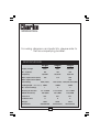
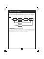
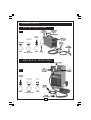
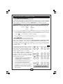
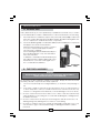
PLASMA CUTTERS
Model Nos.
King 35 • King 50 • King 70
OPERATING & MAINTENANCE
INSTRUCTIONS
1/97
For wiring diagrams and parts lists, please refer to
the accompanying booklet.
SPECIFICATIONS
King35
King50
King70
230V
230V
230/400V
IPH
1PH
3PH
50/60HZ
50/60 HZ
50/60 HZ
Max. Input Current (230V)
18A
31A
46A
Max. Input Current (400V)
-
-
26A
Supply Voltage
No. of phases
Frequency
Fuse Rating
T20A (230V)
Cutting Depth - (Steel Class C)
T30A (230V) T35A(230) T25A(400)
4MM
10MM
15MM
No. Current Settings
1
2
2
Working Air Pressure
5 to 5.5 BAR
5 to 5.5 BAR
5 to 5.5 BAR
100 L/MIN
105 L/MIN
210 L/MIN
IP21
IP21
IP21
H
H
H
30KG
50KG
83KG
250x500x380
456x610x695
456x610x695
Rated Air Delivery
Protection
Insulation Clas
Weight
Dimensions
1
Thank you for purchasing this CLARKE Plasma Cutter .
Before attempting to operate this machine, please read this leaflet thoroughly
and follow the instructions carefully, in doing so you will ensure the safety of yourself
and that of others around you, and you can look forward to the Plasma Cutter
giving you long and satisfactory service.
GUARANTEE
This CLARKE product is guaranteed against faulty manufacture for a period
of 12 months from the date of purchase. Please keep your receipt as proof
of purchase.
This guarantee is invalid if the product is found to have been abused or
tampered with in any way, or not used for the purpose for which it was
intended.
Faulty goods should be returned to their place of purchase, no product
can be returned to us without prior permission.
This guarantee does not effect your statutory rights.
CONTENTS
Page
Specifications ................................................................................................ 1
EMC Regulations .......................................................................................... 3
Safety Precautions - General ...................................................................... 5
Additional Safety Precautions for Plasma Cutters .................................... 7
What is Plasma Cutting ................................................................................. 8
Features ......................................................................................................... 8
Air Supply ....................................................................................................... 9
Front Panel Description ............................................................................... 9
Electrical Connections ................................................................................ 11
Installation & Operation ............................................................................... 12
Duty Cycle .................................................................................................... 14
Maintenance ............................................................................................... 15
Troubleshooting ............................................................................................ 16
2
ELECTROMAGNETIC INTERFERENCE (EMC)
Whilst this unit complies with EMC regulations, the user is responsible for installing
and using the welding equipment according to the manufacturers instructions. If
electromagnetic disturbances are detected then it shall be the responsibility of
the user of the welding equipment to resolve the situation. In some cases this
remedial action may be as simple as earthing the welding circuit, see ‘Note’. In
other cases it could involve constructing an electromagnetic screen enclosing
the power source and the work complete with associated input filters. In all cases
electromagnetic disturbances must be reduced to the point where they are no
longer troublesome.
Note - The welding circuit may or may not be earthed for safety reasons. Changing
the earthing arrangements should only be authorised by a person who is
competent to assess whether the changes will increase the risk of injury, e.g. by
allowing parallel welding current return paths which may damage the earth circuits
of other equipment.
1. Assessment of area
Before installing welding equipment the user shall make an assessment of potential
electromagnetic problems in the surrounding area. Avoid using your inverter in
the vicinity of:
a) other supply cables, control cables, signalling and telephone cables;
above, below and adjacent to the welding equipment;
b) radio and television transmitters and receivers;
c) computer and other control equipment;
d) safety critical equipment, e.g. guarding of industrial equipment;
e) pacemakers and hearing aids etc;
f)
equipment used for calibration or measurement;
g) other equipment in the environment. The user shall ensure that other
equipment being used in the environment is compatible. This may
require additional protection measures;
It may be possible to avoid the above by changing the time of day that welding
or other activities are to be carried out.
The size of the surrounding area to be considered will depend on the structure of
the building and other activities that are taking place. The surrounding area may
extend beyond the boundaries of the premises.
2.
Methods of reducing emissions
2.1 Mains supply
Welding equipment should be connected to the mains supply according to the
manufacturers recommendations. If interference occurs, it may be necessary to
3
take additional precautions such as filtering of the mains supply. Consideration
should be given to shielding the supply cable of permanently installed welding
equipment, in metallic conduit or equivalent. Shielding should be electrically
continuous throughout its length. The shielding should be connected to the welding
power source so that good electrical contact is maintained between the conduit
and the welding power source enclosure.
2.2 Maintenance of the welding equipment
The welding equipment should be routinely maintained according to the
manufacturers recommendations. All access and service doors and covers should
be closed and properly fastened when the welding equipment is in operation.
The welding equipment should not be modified in any way except for those
changes and adjustments covered in the manufacturers
instructions. In particular, the spark gaps of arc striking and stabilizing devices should
be adjusted and maintained according to the manufacturers recommendations.
2.3 Welding cables
The welding cables should be kept as short as possible and should be positioned
close together, running at or close to the floor level.
2.4 Equipotential bonding
Bonding of all metallic components in the welding installation and adjacent to it
should be considered. However, metallic components bonded to the work piece
will increase the risk that the operator could receive a shock by touching these
metallic components and the electrodes at the same time. The operator should
be insulated from all such bonded metallic components.
2.5 Earthing of the workpiece
Where the workpiece is not bonded to earth for electrical safety, nor connected
to earth because of its size and position, e.g. ships hull or building steelwork, a
connection bonding the workpiece to earth may reduce emissions in some, but
not all instances.
Care should be taken to prevent the earthing of the workpiece increasing the risk
of injury to users, or damage to other electrical equipment.
Where necessary, the connection of the workpiece to earth should be made by
a direct connection to the workpiece, but in some countries where direct
connection is not permitted, the bonding should be achieved by suitable
capacitance, selected according to national regulations.
2.6 Screening and shielding
Selective screening and shielding of other cables and equipment in the surrounding
area may alleviate problems of interference. Screening of the entire welding
installation may be considered for special applications.
4
SAFETY PRECAUTIONS
WARNING:
As with all machinery, there are certain hazards involved with their operation
and use. Exercising respect and caution will considerably lessen the risk of
personal injury. However, if normal safety precautions are overlooked, or
ignored, personal injury to the operator may result.
FAILURE TO FOLLOW THESE RULES MAY RESULT IN SERIOUS PERSONAL INJURY
GENERAL PRECAUTIONS
A) Burn prevention
Wear protective clothing - gauntlet gloves designed for use in welding, hat, and
protective shoes. Button shirt collar and pocket flaps, and wear cuffless trousers to
avoid entry of sparks and slag. Wear helmet with safety goggles or glasses with side
shields underneath, appropriate filter lenses or plates (protected by clear cover
glass). This is a MUST for welding or cutting, (and chipping) to protect the eyes from
radiant energy and flying metal. Replace cover glass when broken, pitted, or
spattered. Avoid oily greasy clothing. A spark may ignite them. Hot metal such as
electrode stubs and workpieces should never be handled without gloves. First aid
facilities and a qualified first aid person should be available for each shift unless
medical facilities are close by for immediate treatment of flash burns of the eyes
and skin burns. Ear plugs should be worn when working overhead or in a confined
space. A hard hat should be worn when others work overhead. Flammable hair
preparations should not be used by persons intending to weld or cut.
B) Toxic fume prevention
Severe discomfort, illness or death can result from fumes, vapours, heat, or oxygen
enrichment or depletion that welding (or cutting) may produce. Prevent them
with adequate ventilation. NEVER ventilate with oxygen. Lead-, cadmium-, zinc-,
mercury- and beryllium-, bearing materials, when welded (or cut) may produce
harmful concentrations of toxic fumes. Adequate local exhaust ventilation must
be used, or each person in the area as well as the operator must wear an airsupplied respirator. For beryllium, both must be used. Metals coated with or
containing materials that emit toxic fumes should not be heated unless coating is
removed from the work surface, the area is well ventilated, or the operator wears
an air-supplied respirator. Work in a confined space only while it is being ventilated
and, if necessary, while wearing an air-supplied respirator. Vapours from chlorinated
solvents can be decomposed by the heat of the arc (or flame) to form PHOSGENE,
a highly toxic gas, and other lung and eye irritating products. The ultraviolet
(radiant) energy of the arc can also decompose trichloroethylene and
perchloroethylene vapours to form phosgene. DO NOT WELD or cut where solvent
vapours can be drawn into the welding or cutting atmosphere or where the radiant
energy can penetrate to atmospheres containing even minute amounts of
trichloroethylene or perchloroethylene.
5
C) Fire and explosion prevention
Causes of fire and explosion are:
1) combustibles reached by the arc, flame, flying sparks, hot slag or heated
material;
2) misuse of compressed gases and cylinders;
3) short circuits.
BE AWARE THAT flying sparks or falling slag can pass through cracks, along pipes,
through windows or doors, and through wall or floor openings, out of sight of the
goggled operator. Sparks and slag can fly 10m.
To prevent fires and explosion: keep equipment clean and operable, free of oil,
grease, and (in electrical parts) of metallic particles that can cause short circuits.
If combustibles are in area, do NOT weld or cut. Move the work if practicable, to
an area free of combustibles.
Avoid paint spray rooms, dip tanks, storage areas, ventilators. If the work cannot
be moved, move combustibles at least 10m. away out of reach of sparks and
heat; or protect against ignition with suitable and snug fitting, fire- resistant covers
or shields.
Walls touching combustibles on opposite sides should not be welded on (or cut).
Walls, ceilings, and floor near work should be protected by heat resistant covers
or shields. Fire watcher must be standing by with suitable fire extinguishing
equipment during and for some time after welding or cutting if:
a) appreciable combustibles (including building construction) are within 10m.
b) appreciable combustibles are further than 10m but can be ignited by sparks.
c) openings (concealed or visible) in floors or walls within 10m can expose
combustibles to sparks.
d) combustibles adjacent to walls, ceilings, roofs or metal partitions can be
ignited by radiant or conducted heat.
After work is done, check that area is free of sparks, glowing embers, and flames.
An empty container that held combustibles, or that can produce flammable or
toxic vapours when heated, must never be welded on or cut, unless container
has first been cleaned. This includes
.......a thorough steam or caustic cleaning (or a solvent or water washing,
depending on the combustible’s solubility) followed by purging and inerting with
nitrogen or carbon dioxide, and using protective equipment.
Water filling just below working level may substitute for inerting.
A container with unknown contents should be cleaned (see paragraph above),
do NOT depend on sense of smell or sight to determine if it is safe to weld or cut.
Hollow castings or containers must be vented before welding or cutting - they
can explode.
In explosive atmospheres, never weld or cut where the air may contain flammable
dust, gas, or liquid vapours.
6
ADDITIONAL SAFETY PRECAUTIONS FOR PLASMA CUTTERS
The safety precautions given previously must be strictly adhered to. The following
precautions are additional to, and focus specifically on Plasma Cutters.
✔ALWAYS have a fire extinguisher handy when operating the cutter.
wear protective clothing - overalls, gloves and sturdy footwear, To
✔ALWAYS
avoid the risk of burns,
ensure that the cutting cable, air compressor hose and electrical
✔ALWAYS
input lead are kept well away from the possible ‘spatter’ of hot metal created
when cutting.
operate the cutter in a well ventilated area or an area equipped
✔ALWAYS
with a fume extractor. Check the possibility that the material to be cut will
give off toxic gas or fumes. If there is any doubt, a respirator should worn.
✘ NEVER operate near water or any other liquid.
operate near anything flammable. Whilst plasma cutters do not produce
✘ NEVER
an open flame, they do produce very hot metal during the cutting process, hot
enough to set alight flammable materials, should contact be made.
observe the electric plasma arc with the naked eye. Always wear
✘ NEVER
eye protection such as welding goggles used for oxy-acetylene welding.
Should the cutting cable be burned, replace it NEVER attempt to repair it
✘ yourself.
✘ NEVER operate the machine with the covers removed.
dismantle the tip from the torch unless the machine has been
✘ NEVER
disconnected from the electrical supply.
push the torch nozzle down with your hands unless the machine has
✘ NEVER
been disconnected from the electrical supply.
✘ NEVER cut fuel or lubricant containers, even if they are empty.
✘ NEVER cut containers or casings which contain flammable material.
cut in environments which are polluted by flammable gas or
✘ NEVER
combustible vapours, such as petrol etc.
✘ NEVER point the torch jet at people or animals.
Should you feel sick or develop sore eyes whilst using the plasma cutter, STOP
WORK IMMEDIATELY and move to fresh air. Do not resume cutting until you
have provided good ventilation for the cutting area.
When halogenated solvents or degreasing agents are present, the material
to be cut should be cleaned properly to prevent the formation of toxic gases.
Some chlorinated solvents may decompose in the presence of the radiation
given out by the arc and may generate phosphene gas.
7
WHAT IS PLASMA CUTTING
Plasma Cutting is a fast, clean and distortion free, means of cutting through all
types of metal from mild and stainless steels to aluminium brass and copper.
The process relies upon the chemical reaction of a gas or mixture of gases, such
as air, when subjected to very high temperatures. The gas ionises, i.e. negative
electrons are separated from the atom, leaving the atom positively charged. In
this ionised state, the gas is electrically conductive and is called ‘plasma’.
A standing electric arc is created to achieve the very high temperature required
to create the plasma. By forcing the plasma through a small nozzle the arc is
constricted and its temperature is increased to over 20,000°C and concentrated
into a very small area.
When the plasma is directed at a conductive material (which is connected to
the earth return lead of the cutter) the arc is transferred through the plasma to
the material. The high energy of the arc melts the material which is displaced by
the gas flow.
The standing arc has to be created by producing an ionised path in the gas. This
is achieved by applying a very high voltage, at high frequency, between the
electrode and the tip/work, causing a high frequency spark. The main arc will
ignite as soon as the gas between the tip and the nozzle is ionised.
The power generator is essentially made up of a transformer, a rectifying unit and
an electronic board.
The latter controls the unit safeguards and governs the work cycles of the various
components which make up the unit, such as the solenoid valve, the HF circuit
(for models fitted with this), the power contactor, etc.
FEATURES
The plasma cutting units are supplied with the following safety devices:
1.
Thermal protection devices are installed at the points most subject to high
temperatures such as the power transformers and the rectifying units.
An amber light on the front panel lights up when the thermal protection device
intervenes. See fig.3
2.
A pneumatic protection device prevents damage to the torch due to
switching on with either no air supply or low air pressure.
An amber light on the front panel lights up when the pneumatic protection
device intervenes. See fig. 3
3.
An Electric shock protection device prevents the operator from coming into
contact with the live parts of the torch (such as the electrode, etc.) This consists
of a safety device, built into the body of the torch, which breaks the main
power circuit when the end part of the torch is removed to replace the
electrode or the tip.
When the electrical protection device intervenes, the unit is prevented from
operating.
8
MAIN COMPONENTS
The power generator is essentially made up of a transformer, a rectifying unit
and an electronic board.
The latter controls the unit safeguards and governs the work cycles of the various
components which make up the unit, such as the solenoid valve, the power
contactor, etc.
Fig. 1
MAIN
CONTACTOR
MAIN
TRANSFORMER
MAIN
BRIDGE
PLASMA
TORCH
CONTROL
PCB
AIR INPUT
AIR
SOLENOID
VALVE
AIR SUPPLY
A compressed air supply is required, capable of delivering clean dry air, at a
minimum pressure of 6 Bar, and at a rate of, from 100 to 210 litres per minute,
depending upon the model. (See Specifications on page 2).
9
GENERAL LAYOUT
KING 35 - FRONT PANEL
Fig. 2
Warning Lamps
KING 50 & 70 - FRONT PANEL
Fig. 3
Warning Lamps
10
ELECTRICAL CONNECTIONS
A. KING 35 & KING 50
Connect the mains lead, through a suitably fused isolator switch, to a 230 Volt (50Hz)
electrical supply, having a fuse rating in accordance with that given in the specification
chart on page 2. A standard 13 Amp plug MUST NOT be used with this machine.
WARNING! THIS APPLIANCE MUST BE EARTHED
IMPORTANT: The wires in the mains lead are coloured in accordance with the following code:
Green & Yellow
Blue
Brown
- Earth
- Neutral
- Live
As the colours of the flexible lead of this appliance may not correspond with the
coloured markings identifying terminals in your electrical supply, proceed as follows:
•
Connect GREEN & YELLOW coloured cord to terminal marked with a letter “E” or Earth
symbol “ ” or coloured GREEN or GREEN & YELLOW.
•
Connect BROWN cord to terminal marked with a letter “L” or coloured RED.
•
Connect BLUE cord to terminal marked with a letter “N” or coloured BLACK.
B. KING 70
This model is designed for use with either 230V three phase or 400V three-phase
supply, and should be connected through a suitably fused isolator switch.
The GREEN or GREEN & YELLOW wire should be connected to the EARTH terminal
or terminal marked with “ ” symbol. The other two wires are for connection to
the phase wires.
Fig. 4
The machines are delivered for connection
to a 400V supply, but to be certain, check the
label on the end of the power supply cable,
or remove the cover and visually inspect the
Voltage changeover block. (see fig. 4).
If the supply voltage is changed, a
corresponding change must be made to the
terminal connectors on the ‘Voltage
Changeover’ block, located behind the right
hand side panel, as follows:
1. Ensure the machine is switched OFF, and
completely disconnected from the
electrical supply, or if hard wired, the
fuse should be removed from the circuit.
2.
Remove the right hand side panel by
unscrewing the 6 securing screws.
3.
Change the connections of the ‘Voltage
Changeover’ block, as shown on the
label inside the unit, which is duplicated
above at fig 4.
11
CAUTION: Never operate the
machine with the panels removed.
INSTALLATION AND OPERATION
On receipt, check the unit for any damage which may have occurred during
transportation. You should immediately report such damage to the Clarke dealer
from whom the unit was purchased.
Fig. 5
A. KING 35
This model is provided with a regulator
and air filter assembly, which is mounted
on the rear panel as shown in fig 5.
Attach the air hose by simply pushing the
hose into the connector.
To remove the hose, hold the clamping ring
IN, whilst pulling on the hose, as shown in fig.6
Fig. 6
Attach the handle by snapping the lugs into the
slotted holes in the top of the machine, then
screwing in the two securing screws.
B. KING 50 & KING 70.
(i)
Attach the handle to the unit by inserting the ends into the holes in the upper corners
of the front panel, and securing with the four self tapping screws provided.
(ii) Gently, and with assistance, tip the unit over so that it rests on the handle, and edge
of the front panel, and insert the axle into its’ housing. Attach the wheels, and secure
in position with circlips provided.
(iii) Push the two castors firmly home into the holes provided, and gently lift the machine
to an upright position.
C. ALL MODELS
1.
Connect the power supply cable to a source located as near as possible to the
work area, so that the unit can be switched off quickly in case of emergency. Refer
to ‘Electrical Connections’ on page 12. Fuse ratings are given in the Specification
chart on page 2.
Make sure that the mains supply switch and any fuses have a value which is the
same or 20% above the maximum current absorbed by the unit. (See Specification
chart page 2)
12
2.
Pull out the air pressure reglator knob, (located on the front panel (King 50 & 70), or
at the back of the unit (King 35), and turn it fully clockwise before connecting the
air hose to the compressed air supply. This ensures the regulator is set to its lowest
pressure. Make sure that the supply pressure is at least 6 bar (from 6 to 8 is ideal).
Turn the air supply to the unit ‘on’, and set a pressure of 5 to 5.5 bar by screwing the
regulator knob anticlockwise, whilst observing the pressure on the gauge. When the
pressure is set, lock the knob in position, by pushing it ‘in’.
3.
Fasten the earth clamp to the workpiece. If a metal bench is being used, make sure
it has also been connected to earth by means of a cable with an adequate crosssection. If the surface of the piece to be cut is painted, rusty of covered with insulating
material, clean the surface so that satisfactory contact between the workpiece
and the earth clamp can be obtained.
4. Make sure that the torch has been assembled with the correct components and
that the hole in the tip of the torch complies with the values given in the table below,
according to the cutting current. Simply unscrew the nozzle, and replace with one of
the required size.
5. Switch the unit ON using the main switch (see Figs 2 & 3), Select the appropriate
current in the case of King50 and King70. A hissing of air will be apparent for a short
period, as the air system is charged and the air filter drain valves close
PLASMA UNIT
TORCH
TIP HOLE
(mm)
CUT CURRENT
(Amps)
King 25
Binzel PSB31
1
25
King 50
S54
1
35/50
King 70
A90
1,1•1,4•1,7
40/70
6. Check to ensure the amber lights for air supply, and torch safety, (i.e. Thermal
Overload), situated on the front panel, are off. The green light should be ‘on’, indicating
that the unit is supplied with power.
7.
Press the torch button and check whether the pressure indicated by the pressure
gauge corresponds to the pressure required. At the same time, the Pilot Arc will light.
Because these models are fitted with a Pilot Arc, cutting can commence even on
metal which is painted or coated. However, do be aware that fumes may be given
off by burning paint or coated surfaces.
8.
The pilot arc will go out after 2-3 seconds. If in the meantime cutting has not started,
the torch button should be pressed again so that pilot arc will relight.
CAUTION:
Avoid unnecessary lighting of the pilot arc, to prevent excessive consumption of
the electrode and nozzle.
13
9.
To start cutting, bring the torch with the pilot arc near to the workpiece and the
cutting arc between the torch and the workpiece will immediately light. If piercing
or cutting is to be carried out from the centre of the piece, start cutting with the
torch inclined and then straighten it slowly so that molten metal does not spray onto
the nozzle of the torch. If this operation is to be carried out on thicknesses greater
than 3-4mm, first drill a hole from which the cutting can start.
10. During cutting, rest the nozzle perpendicularly on the surface to be cut without
exerting any force. The wire spacer, mounted on the end of the torch, (except
King 35), should be used in all cutting operations, to maintain the correct gap
between the torch and the workpiece. To move the torch, pull towards you
rather than pushing away from you.
CAUTION:
During cutting, the speed of torch movement should correspond to the
thickness of the workpiece.
Moving too quickly causes a return of incandescent scale towards the torch, which
shortens the life span of the parts most subject to wear and tear.
The build up of scale on the nozzle should be removed as soon as possible.
11. To stop cutting remove the torch from the workpiece. To extinguish the pilot
arc release the trigger on the torch.
Note:
When the trigger is released and the arc is extinguished compressed air will
continue to flow for a period of time, in order to cool the torch. DO NOT switch off
the machine until the air has stopped flowing or damage may occur to the torch.
IMPORTANT WARNING:
WHEN YOU LIFT THE TORCH AWAY FROM THE WORKPIECE THE CUTTING ARC
WILL BE LOST BUT THE PILOT ARC WILL REMAIN IGNITED IN THE NOZZLE UNTIL
THE TORCH TRIGGER IS RELEASED.
NEVER TOUCH THE NOZZLE WHILST THE PILOT ARC IS IGNITED AS THIS MAY
RESULT IN SERIOUS INJURY.
DUTY CYCLE
The duty cycle of a plasma cutting unit is determined by the percentage of use in
a repetitive cycle of 10 minutes with a given cutting current “I2”.
The duty cycle is indicated by the letter “X” on the table of technical specifications
which is screen-printed on the rear panel of the unit.
For example: X=30%
X=100%
I2=50A
I2=30A
In the first case the operator can cut for 3 minutes (30%), with a 50A current; in the
second case the operator can cut for 10 minutes (100%) with a 30A current.
Do not overwork the machine, operating above the established duty cycle may
cause serious damage.
14
MAINTENANCE
A. THE BASE UNIT
If any fault develops, it must repaired by a qualified technician only. Contact
your CLARKE dealer for advice. Maintenance of the unit is limited to the following.
1.
If the machine is in constant use, inspect every 3-4 months, and use dry compressed
air to remove any dust deposit. Ensure all precautions are taken with regard to the
use of compressors to clean the electronic components.
2.
Check the air filter regularly. Condensate is drained off immediately the compressed
air supply is removed from the machine.
Fig. 7
Whenever the machine is not used for 1 week or
more, the compressed air supply should be
disconnected completely.
On models King 50 & 70, the air filter assembly is to
be found beneath the cover, on the left hand
side of the machine.
To drain the condensate, turn the knurled nut (see
fig. 7), anticlockwise so that the drain is fully open.
Remember to screw the nut in again once
the condensate has drained.
B. THE TORCH ASSEMBLY
WARNING
NEVER ATTEMPT TO CARRY OUT ANY MAINTENANCE ON THE TORCH,
UNLESS THE MAINS SUPPLY IS DISCONNECTED
No special tools are required to replace torch parts. Simply unscrew the nozzle
assembly, and all components are easily replaced.
1.
The torch must be kept free of slag at all times, to ensure the free passage of
air.
2.
Check the condition of the electrode. One which is worn, i.e. has a crater 1.5
to 2mm deep at its centre, should be renewed. Unscrew the electrode only
when the cooling air flow has finished, to avoid damage to the torch body.
3. Check to ensure the hole in the nozzle is not too wide or deformed, as this may
cause problems for the cuting arc. A nozzle with a damaged or enlarged hole
should be renewed.
4. Check to ensure the holes in the protective ring are clear. Blocked holes or a
damaged ring may damage the torch due to overheating.
5. Check the condition of the torch sheath, ensuring that no parts are worn or cut,
or there are no signs of electrical discharge. A damaged sheath should be
renewed.
15
TROUBLE SHOOTING
1.
PLASMA CUTTER DOESN’T WORK
Check the indicator lamps on the front panel. If Green light is OFF, check power
cable and electrical input - fuse etc.
If the amber Air Supply light is ON - Check compressed air supply, flow and
pressure.
If Thermal Overload lamp is ON - wait for a while and let the plasma cutter cool
down. It will automatically reset when it is ready to start cutting again.
2.
PLASMA CUTTER DOESN’T WORK
- both amber lights OFF, power light ON.
Check plasma electrode, it may have to be replaced. On the King 35, check
to ensure the safety clip is firmly in place
3.
RAGGED CUT AND LACK OF POWER
Check the hole in the nozzle. If it is burned too big or egg Shaped replace it.
Check the air supply. Make sure that the moisture is drained out of the filter
regulator.
4.
NOT CUTTING AS IT SHOULD
You might be trying to cut metal that is too thick, or you may be trying to cut
too fast. Move the cutting torch slower.
5.
ARC GOES OUT WHEN YOU ARE CUTTING
You are probably moving the torch too slow. Move the Cutting torch faster.
6.
RAGGED EDGES ON THE MATERIAL YOU ARE CUTTING
Air pressure could be set too high on the filter regulator. It should be set at 5
to 5.5 Bar. You could be holding the torch too high above the metal you are
cutting. Always use the wire spacer mounted on the end of the torch to
maintain the correct clearance between the tip, and the workpiece.
16