1
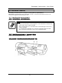
Rockhopper II
Series printer
User’s Guide
MUTOH EUROPE N.V.
AP-75095, Rev : 2.1, 13/07/2004
Rockhopper II series printers – User’s Guide
2
AP-75095, Rev. 2.1, 18/08/2005
Rockhopper II series printers – User’s Guide
COPYRIGHT NOTICE
COPYRIGHT © 2004 Mutoh Europe N.V. All rights reserved.
This document may not be reproduced by any means, in whole or in part, without written permission of the
copyright owner.
This document is furnished to support the Mutoh Rockhopper II Series Printer. In consideration of the
furnishing of the information contained in this document, the party to whom it is given, assumes its custody
and control and agrees to the following:
The information herein contained is given in confidence, and any part thereof shall not be copied or
reproduced without written consent of Mutoh Europe N.V.
This document or the contents herein under no circumstances shall be used in the manufacture or
reproduction of the article shown and the delivery of this document shall not constitute any right or license to
do so.
July 2004
Published: Mutoh Europe N.V., Archimedesstraat 13, B-8400 Oostende, BELGIUM
3
AP-75095, Rev. 2.1, 18/08/2005
Rockhopper II series printers – User’s Guide
4
AP-75095, Rev. 2.1, 18/08/2005
Rockhopper II series printers – User’s Guide
Dear Customer,
The Rockhopper II Eco-Solvent Plus printer series are offered in three different models, i.e. 50.11” (1273
mm), 65.07” (1651 mm) and 88.18” (2280 mm). Printing widths are respectively 1263 mm, 1641 mm and
2250 mm.
Equipped with a new set of 360 nozzles/colour piezo-electric drop-on-demand inkjet heads, the Rockhopper
II combines high speed and high quality printing, with top production speeds of more than 30 m² per hour.
Print resolutions offered are 360 x 360 dpi, 720 x 360 dpi, 720 x 720 dpi, 1440 x 720 dpi and 1440 x 1440
dpi.
Incorporating 8 colour channels, the Rockhopper II series printers can be set up for both 6 and 4 colour
printing. For photo tone output printing, Mutoh offers a as standard 6-colour (CMYK, light cyan & light
magenta) Eco-Solvent Plus ink set. For high speed, the user can load 2 x 4 CMYK ink sets, offering 440 ml
ink autonomy per colour and the possibility to double the machine’s speed. Ink comes in 220 ml smart-chip
ink cassettes.
Rockhopper II application possibilities encompass outdoor poster printing, banners, long-term backlit
signage, building and construction announcements, vehicle graphics, durable indoor graphics, POS
displays, … Apart from outdoor applications, Rockhopper II printers are also an excellent choice for durable
photo-realistic prints for indoors.
The Rockhopper II is an easy to use printer for your outdoor and indoor print jobs.
Happy printing!
Mutoh Europe N.V.
5
AP-75095, Rev. 2.1, 18/08/2005
Rockhopper II series printers – User’s Guide
6
AP-75095, Rev. 2.1, 18/08/2005
Rockhopper II series printers – User’s Guide
TABLE OF CONTENTS
1. Safety Instructions .......................................................................................................................13
1.1. Introduction.............................................................................................................................13
1.2. Warnings, Cautions and Notes................................................................................................13
1.3. Important safety instructions...................................................................................................13
1.4. Warning labels ........................................................................................................................16
1.5. Operation procedure labels .....................................................................................................19
1.6 Labels in function of transportation .........................................................................................20
2. Product Overview ........................................................................................................................21
2.1. Introduction.............................................................................................................................21
2.2. Features ...................................................................................................................................21
2.3. Part names and functions ........................................................................................................22
2.3.1. Front .................................................................................................................................22
2.3.2. Back .................................................................................................................................23
2.3.3. Position and function of the heating elements .................................................................24
2.3.4. Operation panel ................................................................................................................26
2.4. Printer status............................................................................................................................28
2.4.1. Normal .............................................................................................................................28
2.4.2. Setting menu display........................................................................................................28
2.4.3. Changing the printer status ..............................................................................................29
3. Setting up the unit ........................................................................................................................31
3.1. Unpacking ...............................................................................................................................31
3.1.1. Unpacking packaging box of the main unit .....................................................................31
3.1.2. Unpacking stand packaging box ......................................................................................32
3.2. Verification of packaged items ...............................................................................................33
3.2.1. Packaging box of the main unit .......................................................................................33
3.2.2. Accessories box ...............................................................................................................34
3.2.3. Stand packaging box ........................................................................................................34
3.3. Assembly.................................................................................................................................35
3.3.1. Assembling the stand .......................................................................................................35
3.3.2. Installing the stand ...........................................................................................................36
3.3.3. Fixing the printer body onto the stand .............................................................................37
3.3.4. Removal of protective packaging material ......................................................................38
3.3.5. Installing accessories........................................................................................................39
3.4. How to make your printer operative .......................................................................................40
3.5. Installation...............................................................................................................................43
3.5.1. Choosing a place for the printer.......................................................................................43
3.5.2. Installing the printer .........................................................................................................44
7
AP-75095, Rev. 2.1, 18/08/2005
Rockhopper II series printers – User’s Guide
4. Preparing for a job.......................................................................................................................45
4.1. Introduction.............................................................................................................................45
4.2. Connecting the power cable....................................................................................................45
4.3. Connecting the foot switch .....................................................................................................48
4.4. Turning the power ON/OFF....................................................................................................49
4.4.1. Turning the power ON .....................................................................................................49
4.4.2. Turning the power OFF....................................................................................................49
4.5. Installing Eco-Solvent Plus ink cassettes................................................................................51
4.6. Media handling .......................................................................................................................54
4.6.1. Loading sheet media ........................................................................................................54
4.6.2. Loading roll media ...........................................................................................................57
4.6.3. Setting media type............................................................................................................57
4.7. Testprinting .............................................................................................................................59
4.7.1. Setup List .........................................................................................................................60
4.7.2. NozzleCheck ....................................................................................................................61
4.7.3. Alignment ........................................................................................................................61
4.7.4. Colour palette...................................................................................................................62
4.7.5. Maintenance record..........................................................................................................63
4.8. Connecting the printer to your PC ..........................................................................................64
4.8.1. System requirements ........................................................................................................64
4.8.2. Selecting cables................................................................................................................64
4.8.3. Connecting the Centronics interface ................................................................................65
4.8.4. Connecting the network interface ....................................................................................66
5. Handling the printer ....................................................................................................................67
5.1. Introduction.............................................................................................................................67
5.2. Drawing flow ..........................................................................................................................67
5.3. Using media ............................................................................................................................68
5.3.1. Media type........................................................................................................................68
5.3.2. Cautions on handling media.............................................................................................68
5.3.3. Precaution on storing media.............................................................................................69
5.3.4. The printing area ..............................................................................................................69
5.3.5. Media feed compensation ................................................................................................70
5.3.6. Details about Rockhopper II media .................................................................................72
5.4. Menu setup on the operation panel .........................................................................................73
5.4.1. Setup menu.......................................................................................................................74
5.4.2. Ink status menu ................................................................................................................76
5.4.3. Origin setup menu............................................................................................................77
5.4.4. Test print menu ................................................................................................................78
5.4.5. Media setup menu ............................................................................................................79
5.4.6. Media type menu..............................................................................................................79
5.4.7. User media menu .............................................................................................................80
5.4.8. Thin Out: Ink amount menu.............................................................................................82
5.4.9. InkDry menu ....................................................................................................................82
5.4.10. Head Height menu .........................................................................................................83
5.4.11. Stiff menu.......................................................................................................................83
5.4.12. Thickness menu..............................................................................................................84
8
AP-75095, Rev. 2.1, 18/08/2005
Rockhopper II series printers – User’s Guide
5.4.13. Heater menu ...................................................................................................................84
5.4.14. Drier menu .....................................................................................................................85
5.4.15. Fixer menu .....................................................................................................................85
5.4.16. Post Fixer menu .............................................................................................................86
5.4.17. HStatus menu Rockhopper II.........................................................................................86
5.4.18. HStatus menu Rockhopper II 4H ...................................................................................87
5.4.19. Media feed compensation menu ....................................................................................87
5.4.20. Change media feed compensation value menu ..............................................................88
5.4.21. Printing by Media feed compensation menu..................................................................88
5.4.22. Cut size menu.................................................................................................................89
5.4.23. Top feed menu ...............................................................................................................89
5.4.24. Media cut menu..............................................................................................................90
5.4.25. Shortest cut menu...........................................................................................................90
5.4.26. Printing mode menu .......................................................................................................91
5.4.27. Printing mode setup menu..............................................................................................91
5.4.28. Colour mode menu.........................................................................................................92
5.4.29. Printing quality menu.....................................................................................................92
5.4.30. InterLace Setup menu ....................................................................................................93
5.4.31. Printing direction menu..................................................................................................93
5.4.32. Repeat printing menu .....................................................................................................93
5.4.33. Repeat times menu .........................................................................................................94
5.4.34. Interval time menu .........................................................................................................94
5.4.35. Head speed menu ...........................................................................................................94
5.4.36. Command setup menu....................................................................................................95
5.4.37. Command select menu ...................................................................................................96
5.4.38. Print step menu...............................................................................................................96
5.4.39. Print position menu ........................................................................................................96
5.4.40. Terminator menu............................................................................................................97
5.4.41. Image resolution menu...................................................................................................97
5.4.42. Online time out menu.....................................................................................................98
5.4.43. Overwrite menu..............................................................................................................98
5.4.44. Halftone menu................................................................................................................99
5.4.45. Layout setup menu .........................................................................................................99
5.4.46. Layout method menu ...................................................................................................100
5.4.47. Joint printing menu ......................................................................................................100
5.4.48. Cutting position Menu .................................................................................................100
5.4.49. Function setup menu ....................................................................................................101
5.4.50. CMY Æ K menu..........................................................................................................101
5.4.51. Scale menu ...................................................................................................................102
5.4.52. Mirror menu .................................................................................................................102
5.4.53. Roll Media setup menu ................................................................................................103
5.4.54. Roll media length menu ...............................................................................................103
5.4.55. Centronics menu ..........................................................................................................103
5.4.56. Network setting menu ..................................................................................................104
5.4.57. IP address menu ...........................................................................................................105
5.4.58. Subnet mask menu .......................................................................................................105
5.4.59. Gateway menu .............................................................................................................106
5.4.60. DHCP menu .................................................................................................................106
5.4.61. MAC address menu......................................................................................................106
9
AP-75095, Rev. 2.1, 18/08/2005
Rockhopper II series printers – User’s Guide
5.4.62. Version menu ...............................................................................................................107
5.4.63. Utility menu .................................................................................................................107
5.4.64. ErrorDisplay menu.......................................................................................................108
5.4.65. Media detection menu..................................................................................................108
5.4.66. Power on cleaning menu ..............................................................................................109
5.4.67. Media width menu .......................................................................................................109
5.4.68. Print and wipe menu ....................................................................................................110
5.4.69. File management setup menu.......................................................................................111
5.4.70. Write mode menu.........................................................................................................112
5.4.71. Re-print menu ..............................................................................................................113
5.4.72. File delete menu ...........................................................................................................114
5.4.73. Re-name menu .............................................................................................................114
5.4.74. Format menu ................................................................................................................115
5.4.75. Initialize setup menu ....................................................................................................116
5.4.76. All Initialize menu .......................................................................................................117
5.4.77. Media setup Initialize menu.........................................................................................118
5.4.78. Printing mode initialize menu ......................................................................................118
5.4.79. Command setup Initialize menu ..................................................................................118
5.4.80. Layout Setup Initialize menu .......................................................................................119
5.4.81. Function setup Initialize menu.....................................................................................119
5.4.82. Roll media setup Initialize menu .................................................................................119
5.4.83. Centronics Initialize menu ...........................................................................................120
5.4.84. Network Initialize menu...............................................................................................120
5.4.85. Utility Initialize menu ..................................................................................................120
5.4.86. File management Initialize menu.................................................................................121
5.4.87. WEB password initialize menu....................................................................................121
5.4.88. Data dump menu ..........................................................................................................121
5.4.89. Ink Manager menu .......................................................................................................122
5.4.90. Head Wash menu .........................................................................................................122
5.4.91. Ink Load menu .............................................................................................................123
5.4.92. Ink Change menu .........................................................................................................123
5.4.93. Cutter change menu .....................................................................................................124
5.4.94. Wiper clean menu ........................................................................................................124
5.4.95. Tank change menu .......................................................................................................125
5.4.96. Tubing Flush menu ......................................................................................................125
5.4.97. Version Check menu....................................................................................................126
5.5. Operating from the operation panel ......................................................................................127
5.5.1. Controlling the heater elements on the Rockhopper II printer.......................................127
5.5.2. Controlling the heater elements on the Rockhopper II 4H printer.................................129
5.5.3. Feeding media ................................................................................................................132
5.5.4. Operating the pressure rollers ........................................................................................132
5.5.5. Print mode check............................................................................................................133
5.6. Operations after printing .......................................................................................................134
5.6.1. Cutting media.................................................................................................................134
5.6.2. Media cutting procedure ................................................................................................135
10
AP-75095, Rev. 2.1, 18/08/2005
Rockhopper II series printers – User’s Guide
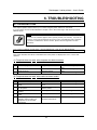
6. Troubleshooting .........................................................................................................................137
6.1. Introduction...........................................................................................................................137
6.2. Failures and malfunctions of the printer ...............................................................................137
6.3. Error messages ......................................................................................................................144
6.3.1. Status messages..............................................................................................................144
6.3.2. Message type error display and solutions ......................................................................145
6.3.3. Data error display and solutions.....................................................................................146
6.3.4. Command error display and solutions ...........................................................................147
6.3.5. Error requiring a restart..................................................................................................147
6.4. When media jams occur........................................................................................................149
6.4.1. How to remove a piece of media (cut media) ................................................................149
6.4.2. How to remove a piece of media (roll media) ...............................................................149
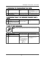
7. Daily Maintenance .....................................................................................................................151
7.1. Introduction...........................................................................................................................151
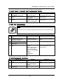
7.2. Replacing consumables.........................................................................................................151
7.3. Cleaning ................................................................................................................................161
7.4. Changing Ink Types ..............................................................................................................168
7.5. Transfer and transportation ...................................................................................................170
7.6. Periodical Services................................................................................................................172
7.6.1. Service by end-user........................................................................................................172
7.6.2. Service by authorised Mutoh technician........................................................................172
7.7 End-user service.....................................................................................................................174
7.7.1 Replacing the wipers and wiper arm...............................................................................174
7.7.2 Replacing the absorbents ................................................................................................177
8. Appendix .....................................................................................................................................179
8.1. Introduction...........................................................................................................................179
8.2. 2 or 4 heater...........................................................................................................................179
8.3. Product Specifications...........................................................................................................180
8.4. Interface Specifications.........................................................................................................182
8.5. Installation of other parts ......................................................................................................184
11
AP-75095, Rev. 2.1, 18/08/2005
Rockhopper II series printers – User’s Guide
12
AP-75095, Rev. 2.1, 18/08/2005
Rockhopper II series printers – User’s Guide
1. SAFETY INSTRUCTIONS
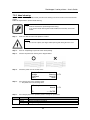
1.1. INTRODUCTION
This chapter explains the meaning of safety terms for personnel who operate this equipment, important
safety instructions, and the positions of the warning labels.
Important :
•
Be sure to follow all instructions and warnings in this manual when using the
equipment.
1.2. WARNINGS, CAUTIONS AND NOTES
Safety terms in this manual and the contents of warning labels attached to the printer are categorized into
the following three types depending on the degree of risk (or the scale of accident).
Read the following explanations carefully and follow the instructions in this manual.
Safety terms
Important
Caution
Notes
Details
Must be followed carefully to avoid death or serious bodily injury
Must be observed to avoid bodily injury (moderately or lightly) or damage to your
equipment
Contains important information and useful tips on the operation of your printer
1.3. IMPORTANT SAFETY INSTRUCTIONS
General safety instructions that must be observed to use the equipment safely are explained below.
¾
Do not place the printer in the following areas. Doing so may result in the printer tipping or falling
over and causing injury.
• Unstable surfaces
• Angled place
• Areas subject to vibration by other equipment
¾
Do not stand on or place heavy objects on your printer. Doing so may result in the printer tipping
or falling over and causing injury.
¾
Do not cover the ventilation hole of your printer with cloth, such as a blanket or table cloth. Doing
so could obstruct ventilation and cause fire.
¾
Do not place the printer in humid and dusty areas. Doing so may result in electrical shock or fire.
¾
Do not use a damaged power cable. Doing so may result in electrical shock.
¾
Do not attempt to plug in electrical plugs with wet hands. Doing so may result in electrical shock.
13
AP-75095, Rev. 2.1, 18/08/2005
Rockhopper II series printers – User’s Guide
¾
Do not connect earth cables in the following areas.
• Gas pipes → Doing so may cause fire or an explosion.
• Earth terminals for telephone line or lightening rod → Doing so may cause a large flow of
voltage if lightening occurs.
• Water pipes or faucets → If there is a plastic part in the pipe, the earth will not work
properly.
¾
Do not insert or drop metal or inflammable objects into openings, such as ventilation outlets.
Doing so may result in electrical shock and fire.
¾
Stop using your printer if a liquid is spilled into it. This may cause electrical shock or fire. Turn the
printer off as soon as possible, unplug the power cord, and contact your local MUTOH dealer.
¾
Be sure to use the attached cable. Otherwise, electrical shock or fire may occur.
¾
Be sure to use the specified voltage (AC 100 V to 120V, or AC 220V to 240V). Otherwise,
electrical shock or fire may occur.
¾
Use electricity directly from a power outlet (AC 100 V to 120V, or AC 220V to 240V). Do not put
many loads on one electrical output. Otherwise, heat may be generated and cause fire.
¾
Be sure to use an outlet with an earth terminal and use the terminal correctly. Otherwise,
electrical shock or fire may occur.
¾
Follow the instructions below when handling the power cable.
o Do not modify the cable.
o Do not put heavy objects on the cable.
o Do not bend, twist or pull the cable.
o Do not wire the cable near equipment that generates heat.
¾
Follow the instructions below when handling the power plug. Otherwise, fire may occur.
o Wipe away dust and any other residue before inserting the plug.
o Ensure that the plug is firmly inserted as far as it will go.
¾
When handling the foot switch, be aware of the following:
o Do not place anything heavy on the foot switch.
o Do not bend the cable of the foot switch with force and do not pull.
o Do not place the foot switch near thermal devices.
¾
When handling ink cassettes, be careful that ink does not get in your eyes or on your skin.
However, if this happens, flush immediately with water. Otherwise, your eyes may become
congested or inflamed slightly. If you feel discomfort, consult a doctor immediately.
¾
Do not disassemble ink cassettes. Otherwise, ink may get in your eyes or on your skin.
¾
Be careful not to pinch your fingers when opening and closing the cover of the ink compartment.
¾
Be careful not to pinch your fingers when opening and closing the front cover.
¾
Follow the instructions below when connecting the network interface cable. Otherwise, electrical
shock or fire may occur.
o Do not touch the connector.
o Do not connect the network cable connector that is not the same specification to the
interface board.
¾
When cutting the roll media, be careful of the following. Incorrect handling can result in injury to
the hands and fingers from the razor blade.
o When holding the media, do not place fingers over the media cut groove.
o Move the razor blade slowly along the media cutting groove.
14
AP-75095, Rev. 2.1, 18/08/2005
Rockhopper II series printers – User’s Guide
¾
Do not use thinner, benzene, alcohol or other active agents. Doing so may result in damage or
paint peeling from the casing.
¾
Be careful not to spill water inside the printer. Doing so may result in a short circuit.
¾
Be careful not to touch the heaters during or after operation. Doing so may result in burns.
¾
Only use Eco-Solvent Plus ink and appropriate cleaning liquid. Using other ink (e.g. dye or
pigment) will cause permanent damage to the printer.
¾
Never open the covers fixed with screws. Doing so may result in electrical shock or a
malfunctioning in the printer.
¾
Do not touch the cutter blade. Doing so may result in bodily injury.
¾
Do not cut hard objects or drop the cutter. Doing so may damage or chip the cutter blade.
¾
Do not bend or pull the waste fluid tube. Doing so may cause that the waste fluid will leak out and
malfunction in the product.
¾
Do not touch the cleaning wiper or the head cap unit while cleaning the cleaning wiper. Doing so
may result in poor head cleaning because of oil on your hands.
¾
Do not tilt the printer, stand it against a wall or turn it upside down. Doing so may cause ink to
leak inside the printer. Movement after transport is also not covered by the warranty.
¾
When installing options, do not touch the elements on the circuit board. The elements on the
boards can be very hot and can cause burns.
¾
Have four or more people unpack and assemble the printer.
¾
When lifting the printer out of the packing box, be sure to remove the vinyl cover first, and then
grab the holding grips on the sides of the printer. Lifting the printer with the vinyl cover on may
cause your hands to slip and drop or damage the printer.
¾
Have two or more people transport the printer.
¾
Ensure that the plug has been disconnected from the power socket when it is not to be used for a
long time.
¾
Earth wires must be connected to wires or terminals that fulfill the conditions below.
o Earth terminals of power sockets
o Earth wires with copper morsel that is at least 650 mm under the ground
¾
Earth wires must be connected to wires or terminals that fulfill the conditions below.
¾
When setting roll media, place it on top of a desk or other flat surface. Setting roll media with the
scroller standing up may damage them.
¾
Keep the printer horizontal during transportation.
¾
Be sure to do the following before attaching options.
o Turn the printer off.
o Unplug the power cord from the socket.
o Unplug cables connected to the printer. Otherwise, damage to the printer or your computer
may occur.
o Remove electrostatic charge from your clothes and body by touching the metal parts of the
printer.
o Electronic components such as the memory may malfunction if exposed to an electrostatic
charge.
15
AP-75095, Rev. 2.1, 18/08/2005
Rockhopper II series printers – User’s Guide
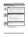
1.4. WARNING LABELS
The handling, attachment locations, and types of warning labels are explained below.
Warning labels are attached on areas which require attention. Read and understand the positions and
contents thoroughly before performing your work.
1.4.1. Handling the warning labels
Be sure to note the following when handling the labels.
Notes :
•
•
•
Make sure that all labels can be recognized. If text or illustrations cannot be seen
clearly, either clean or replace the label.
When cleaning labels, use a cloth with water or neutral detergent. Do not use a
solvent or gasoline.
If a warning label is damaged, lost or cannot be recognized, replace the label.
When replacing warning labels, contact your local MUTOH dealer.
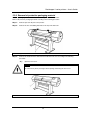
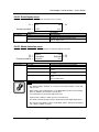
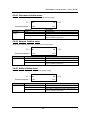
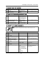
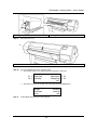
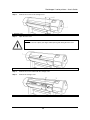
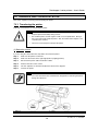
1.4.2. Locations and types of warning labels
The locations of warning labels are shown below.
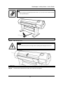
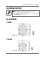
1.4.2.1. Location and types of warning labels on front part.
16
AP-75095, Rev. 2.1, 18/08/2005
Rockhopper II series printers – User’s Guide
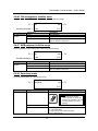
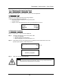
No.
1
Type
CAUTION
VORSICHT
ATTENTION
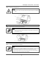
> Do not open the front cover or touch the media during printing.This will result in poor image quality.
> If no printing is to be done for some time, remove the media and put the hold lever in the up
position. Otherwise the media may lift up and become wrinkled and you will not be able to obtain
good printing results.
> Öffnen Sie wärhend des Druckens die Frontabdeckung nicht und berühren Sie das
Druckmaterial nicht.
> Wenn Sie wärhend längere Zeit den Drucker nicht benutzen, nehmen Sie das Druckmaterial
heraus und stellen Sie den Halthebel in die obersten Position. Sonst kann sich das Druckmaterial
aufheben und zerknittern und demzufolge erzielen Sie keine gute Druckergebnisse mehr.
> N'ouvrez pas le couvercle quand l'imprimante est en train d'imprimer. Ne touchez pas non plus
le papier afin d'éviter que la qualité s'aggrave.
> Si vous ne comptez pas imprimer pendant un certain temps, retirez le papier et mettez le levier
en position levée. Sinon, le support risque de se soulever et de se froisser et vous n'obtiendrez
pas de bonne qualité d'impression.
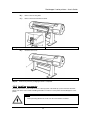
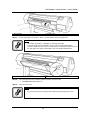
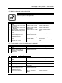
2
CAUTION
VORSICHT
ATTENTION
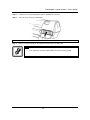
> To avoid injury, keep fingers away from the
cutter blade.
> Um Verletzungen zu vermeiden, berürhen Sie das
Schneidemesser nicht.
> Ne touchez pas la lame afin d'éviter des blessures.
> To avoid injury, do not touch the edge of the
steel belt.
> Um Verletzungen zu vermeiden, berühren Sie den
Stahl-Antriebsriemen nicht .
> Ne touchez pas la courroie de transmission en
acier afin d'éviter des blessures.
A
Only onto the Rockhopper II 4H printer
17
AP-75095, Rev. 2.1, 18/08/2005
Rockhopper II series printers – User’s Guide
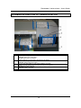
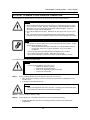
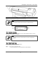
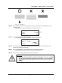
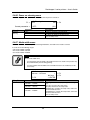
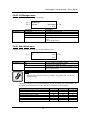
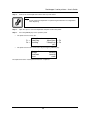
1.4.2.2. Location and types of warning labels on back part.
No.
3
Type
CAUTION
THIS UNIT HAS TWO POWER SUPPLY CORDS, WHEN WiNDING
UNIT IS PROVIDED. TO REDUCE THE RISK OF ELECTRICAL
SHOCK, DISCONNECT ALL POWER SUPPLY CORDS
BEFORE SERVICING.
18
AP-75095, Rev. 2.1, 18/08/2005
Rockhopper II series printers – User’s Guide
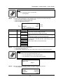
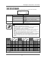
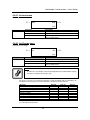
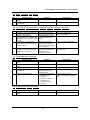
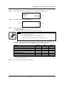
1.5. OPERATION PROCEDURE LABELS
The handling, attachment locations and types of operation procedure labels are explained below.
Your printer has labels, which explain the operations that require particular care. Read and understand the
locations and contents of these labels thoroughly before performing your work.
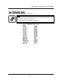
No.
6
Type
Refer to
Æ Installing ink cassettes
Number
of the
Colours
Ink Type
1
2
4
Eco Solvent
2x4 colours
Black
Yellow
6
Eco Solvent
1x6 colours
Black
Cyan
Slot Number of Ink Cartridge
4
3
5
6
Cyan
Magenta Magenta
Transition Transition
Liquid
Liquid
Yellow
7
8
Cyan
Yellow
Black
Magenta
Light
Cyan
Light
Magenta
Please note that ink
cassettes order is different
for 87” printers versus 50”
and 64” printers.
(Label 50” and 64” printer)
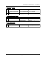
6
Æ Installing ink cassettes
Number
of the
Colours
Ink Type
4
Eco Solvent
2x4 colours
Black
6
Eco Solvent
1x6 colours
Black
1
2
Cyan
Slot Number of Ink Cartridge
4
3
5
6
Magenta
Yellow
Black
Cyan Transition Transition Yellow
Liquid
Liquid
Cyan
Magenta
7
8
Magenta Yellow
Light
Cyan
Light
Magenta
Please note that ink
cassettes order is different
for 87” printers versus 50”
and 64” printers.
(Label 87” printer)
19
AP-75095, Rev. 2.1, 18/08/2005
Rockhopper II series printers – User’s Guide
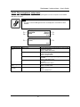
1.6 LABELS IN FUNCTION OF TRANSPORTATION
Nr.
1
2
3
4
5
Description
BEFORE powering on printer,
REMOVE clamp from waste tubes:
On right bottom side of machine!
Remove dummy cassettes before powering on the printer.
BEFORE powering on printer;
REMOVE clamps from waste tubes
You can also find a label on each of the 8 dummy cassettes:
Dummy cassette, please remove before powering on the printer.
BEFORE powering on printer,
REMOVE dummy cassettes.
Plastic bag with the 8 waste tubes and clamps
20
AP-75095, Rev. 2.1, 18/08/2005
Rockhopper II series printers – User’s Guide
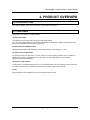
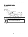
2. PRODUCT OVERVIEW
2.1. INTRODUCTION
This chapter explains the features, part names, and functions of the printer.
2.2. FEATURES
The features of the printer are explained below.
(1) High speed output
3 models feature new print heads and achieve high speed printing.
They also offer printing widths up to 1263 mm in Rockhopper II-50 (50 inch), 1643mm in Rockhopper II-64
(64 inch) and 2230 mm in Rockhopper II-87 (87 inch).
(2) Wide variety of compatible media
Adjustable head height can be adapted to various media thickness from 0.08 up to 1.1 mm.
(3) Vibrant Colour Reproduction
To reproduce sharp and vivid colour, 4 or 6 ink colours are used for printing. 220ml of large capacity EcoSolvent Plus cassette is equipped with an IC chip, which can automatically detect the ink quantity,
significantly improving productivity.
(4) Effective usage of media
A JOG feature is provided allowing the user to set the printing position. Because printing can be performed
on media on which there has already been printed, excess space can be used effectively.
(5) RIP
Software Starter Pack included in-the-box. (To be defined with the order.)
21
AP-75095, Rev. 2.1, 18/08/2005
Rockhopper II series printers – User’s Guide
2.3. PART NAMES AND FUNCTIONS
Part names and functions are explained below.
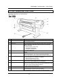
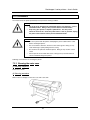
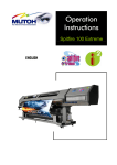
2.3.1. Front
No.
1
Name
Operation panel
2
3
Ink compartment
Front cover
4
Pressure rollers
5
Maintenance cover
6
Stand
7
Media cut groove
8
Cassette cover
9
10
Foot switch
Paper Guide
Function
This panel is used to set operational conditions, the status of the
printer and other functions.
This is the place for installing ink cassettes.
This cover keeps the operator safe from the drive parts of the printer
while it is operating. Only open and/or close the cover to perform
following operations:
¾ Media setting and replacement
¾ Cutter blade replacement
¾ Cleaning the cleaning wiper
¾ In case of media jam.
This roller is used to press the media from above and keep it flat when
printing.
This protects users from electric shocks caused by touching the
internal electrical parts. The cover is opened when expansion
memory (optional) has to be installed, and is closed for normal use.
This stand is used to install the printer on a surface flat floor.
The following options are available for installation.
¾ Motorized roll-up/roll-off system
¾ Take-up system + scroller receiver
Only onto the Rockhopper II 4H printer!
Used to cut the media straight when it is cut manually.
Only onto the Rockhopper II printer!
This is a cover to protect the user from the internal components of the
unit. This is opened during following operation :
¾ When cleaning the cleaning wiper
This switch is used to raise and lower the pressure rollers.
Support the media during printing
In the Rockhopper II it houses post-heater (dryer).
In the Rockhopper II 4H it houses the fixer, post-fixer and dryer.
22
AP-75095, Rev. 2.1, 18/08/2005
Rockhopper II series printers – User’s Guide
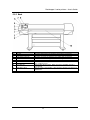
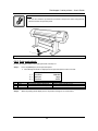
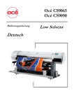
2.3.2. Back
No.
1
2
3
4
5
6
7
8
Name
AC inlet
Interface connector
Foot switch connector
Insertion slot
Interface slot 1
Interface slot 2
Interface slot 3
Hard disk slot
9
Nameplate rating
10
Rear Heater
Function
This is the inlet interface to which the power plug is connected.
This is the connector to which the interface cable is connected.
This is the connector to which the foot switch cable is attached.
This is the slot for inserting media when loading it.
The network interface board attaches here.
This is not used for this printer.
Close it with the cover.
The hard disk attaches here. When not using a hard disk, keep the
cover closed.
The type, name, serial number, rating and other details of the printer are
labelled here.
Supports the media during printing and houses the pre-heaters.
23
AP-75095, Rev. 2.1, 18/08/2005
Rockhopper II series printers – User’s Guide
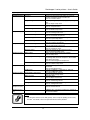
2.3.3. Position and function of the heating elements
Notes :
•
To verify if your printer is equipped with 2 or 4 heaters, please refer to the chapter
“Appendix”.
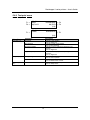
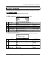
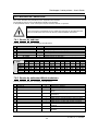
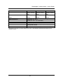
2.3.3.1. Rockhopper II 2 heater printers
Heater element
Pre-heater (Heater A)
Temperature
20 – 50°C
Function
→ Open the pores to make the media more receptive
for eco-solvent plus ink.
Dryer (Heater D)
20 – 50°C
→ Applying heating immediately after printing
improves ink/media anchorage.
→ The dryer helps to make the media touch-dry before
it reaches the automatic take-up system.
There have been a number of requests from the field, asking the heaters to be on by default for a few user
settings. This has now been implemented as follows:
1) For user 1 and user 8 default settings are as follows:
a. Pre heater A: 50°C
b. Dryer D:
50°C
2) For users 2 Î 7, by default the heaters are still OFF.
Notes :
•
Please note some RIP software do not allow selection of the user from software
side. In some cases, however, they do automatically activate user 8.
24
AP-75095, Rev. 2.1, 18/08/2005
Rockhopper II series printers – User’s Guide
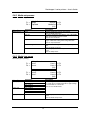
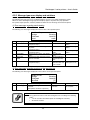
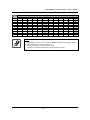
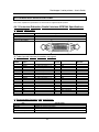
2.3.3.2. Rockhopper II 4 heater printers
Heater element
Pre-heater (Heater A)
Temperature
20 – 50°C
Function
→ Open the pores to make the media more receptive
for eco-solvent plus ink.
Fixer (Heater B)
20 – 70°C
→ To establish optimum fixation onto the media
(coated and uncoated).
→ Optimizes the dot gain control.
Post-Fixer (Heater C)
20 – 70°C
→ The post-fixer finalizes the fixation process and
helps to make the prints touch-dry.
Dryer (Heater D)
20 – 50°C
→ The dryer completes the drying for compatibility
with the take-up in combination with higher output
speeds.
→ Stickiness of printed banner materials is improved.
There have been a number of requests from the field, asking the heaters to be on by default for a few user
settings. This has now been implemented as follows:
1) For user 1 and user 8 default settings are as follows:
a. Pre heater A: 50°C
b. Fixer B:
55°C
c. Post Fixer C: 50°C
d. Dryer D:
50°C
2) For users 2 Î 7, by default the heaters are still OFF.
Notes :
•
Please note some RIP software do not allow selection of the user from software
side. In some cases, however, they do automatically activate user 8.
25
AP-75095, Rev. 2.1, 18/08/2005
Rockhopper II series printers – User’s Guide
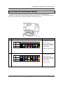
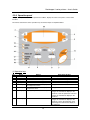
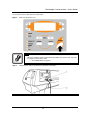
2.3.4. Operation panel
The operation panel is used to set operational conditions, display the status of the printer, and set other
functions.
The names and functions of the operation keys and status lamps are explained below.
(1) Operation keys
No.
1
2
3
4
5
6
Name
[POWER] key
[F1] key
[F2] key
[F3] key
[F4] key
[MENU ↑] key
7
[MENU ↓] key
8
[ENTER] key
Normal
Turns the printer on and off.
Executes the function assigned to F1.
Executes the function assigned to F2.
Executes the function assigned to F3.
Executes the function assigned to F4.
Changes the LCD monitor display to
the setup menu status.
Changes the LCD monitor display to
setup menu status.
Displays the print mode currently set.
9
[CANCEL] key
-
26
Setup menu display
Turns the printer on and off.
Executes the function assigned to F1.
Executes the function assigned to F2.
Executes the function assigned to F3.
Executes the function assigned to F4.
Changes the menu in reverse order.
Changes the menu in forward order.
Determines the new parameter value and
changes the LCD monitor display to the
next menu. Sets the parameter value and
changes the LCD monitor display to the
next menu.
Cancels the new parameter value and
changes the LCD monitor display to the
next menu. Clears the parameter value
and changes the LCD monitor display to
the next menu.
AP-75095, Rev. 2.1, 18/08/2005
Rockhopper II series printers – User’s Guide
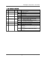
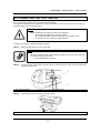
(1) LCD monitor and status lamps
No.
10
Name
LCD monitor
Colour
-
11
POWER lamp
Green
12
ERROR lamp
Red
13
DATA lamp
Orange
14
MEDIA SET lamp
Orange
Status
ON
OFF
Flashing
OFF
ON
Flashing
OFF
ON
OFF
15
ROLL lamp
Orange
16
SHEET lamp
Orange
HEATER lamp
Orange
17
ON
OFF
ON
OFF
ON
Flashing
OFF
Function
The monitor displays the operation status and error
messages of the printer.
The printer is on.
The printer is off.
An error has occurred. The contents will be displayed on
the LCD monitor.
Either there is no error or the power is off.
The printer is receiving print data.
The printer is analysing received data.
The printer is waiting to receive print data.
¾ The pressure roller is in the release position.
¾ Media has not been loaded.
¾ The pressure roller is in the secured position.
¾ The media has not been loaded.
The media type is set to roll media.
The media type is set to sheet media.
The media type is set to sheet media.
The media type is set to roll media.
The temperature of the heating elements is the requested
temperature.
The real temperature is the same as the requested
temperature.
The heating elements are warming up.
The real temperature is different as the requested
temperature.
The heating elements are powered OFF.
27
AP-75095, Rev. 2.1, 18/08/2005
Rockhopper II series printers – User’s Guide
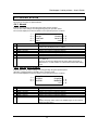
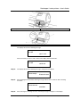
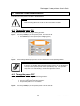
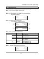
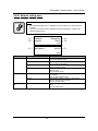
2.4. PRINTER STATUS
The status of the printer is explained below.
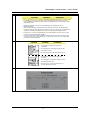
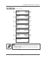
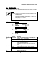
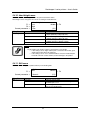
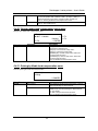
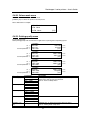
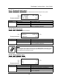
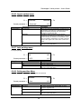
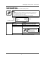
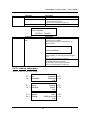
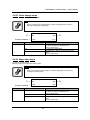
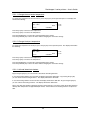
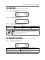
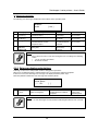
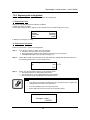
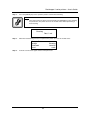
2.4.1. Normal
Indicates that the printer can draw print data when media is loaded.
You can also make settings concerning printing using the operation panel.
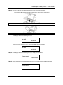
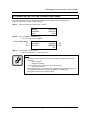
The contents displayed on the LCD monitor of the operation panel is as follows.
1→
2→
4→
6→
No.
1
Position
1st line
2
3
4
5
6
7
Left of 2nd line
Right of 2nd line
Left of 3rd line
Right of 3rd line
Left of 4th line
Right of 4th line
Ready to print
Heaters
Cut&Feed
User 1
Cleaning ← 3
Lever Up ← 5
xxxm ← 7
Description
Displays the current status of the printer. Depending on the status, the
contents may be displayed in 2 to 4 lines.
Displays the function assigned to [F1] key.
Displays the function assigned to [F2] key.
Displays the function assigned to [F3] key.
Displays the function assigned to [F4] key.
Displays the currently set media type.
Displays the approximate amount of remaining media that is currently
set. (Units: m)
However, the amount is displayed only when either "Roll media 1",
"Roll media 2", or "Roll media 3" is selected in the Roll media setting
menu.
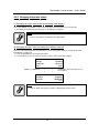
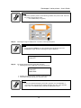
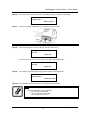
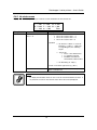
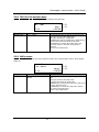
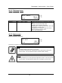
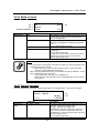
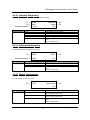
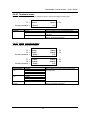
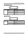
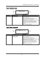
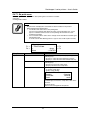
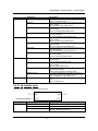
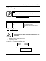
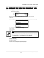
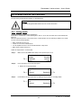
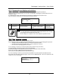
2.4.2. Setting menu display
Indicates that you can make settings concerning printing using the operation panel.
Operation regarding printing is possible via the operation panel.
The contents displayed on the LCD monitor of the operation panel is as follows.
1 → * SetupMenu *
2 → InkStatus
4 → TestPrint
No.
1
2
3
4
5
6
Position
1st line
Left of 2nd line
Right of 2nd line
Left of 3rd line
Right of 3rd line
4th line
OriginSet ← 3
MediaSet ← 5
(1/7) ← 6
Description
Displays the setting menu name currently set.
Displays the function assigned to [F1] key.
Displays the function assigned to [F2] key.
Displays the function assigned to [F3] key.
Displays the function assigned to [F4] key.
Displays the currently available functions of the [F1] key to the [F4]
key.
Displays the page status if there are multiple pages for the currently
displayed setting menu.
28
AP-75095, Rev. 2.1, 18/08/2005
Rockhopper II series printers – User’s Guide
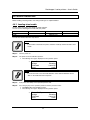
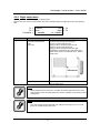
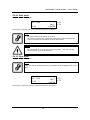
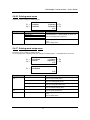
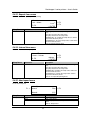
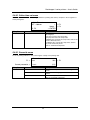
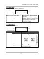
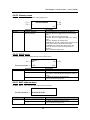
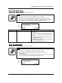
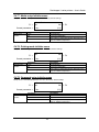
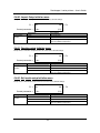
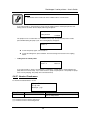
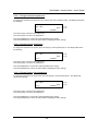
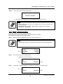
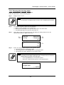
2.4.3. Changing the printer status
To change the printer status, follow the steps below.
(1) Changing the status from normal to the setting menu display
Press either [MENU Ç] or [MENU È] on the operation panel when the printer is in normal status.
¾ The display of the operation panel changes to the Setting menu display.
Notes :
•
Refer to "Setup menu" for details of the setting menu.
(2) Changing the status from the setting menu display to normal
Take one of the following actions when the printer is in the setting menu display to change the operation
panel display to normal one.
¾ Press the [CANCEL] key on the operation panel.
¾ Leave the printer as it is for 3 minutes when the status is in the setting menu display.
Ready to print
Heaters
Cut&Feed
User 1
[MENU ↑] or [MENU ↓]
↓
↓
Cleaning
Lever Up
xxxm
↑
↑
* SetupMenu *
InkStatus
TestPrint
[CANCEL] or leave the printer as it is
for 3 minutes
OriginSet
MediaSet
(1/7)
Notes :
•
Refer to ’Status messages" for details of displaying the printer status.
29
AP-75095, Rev. 2.1, 18/08/2005
Rockhopper II series printers – User’s Guide
30
AP-75095, Rev. 2.1, 18/08/2005
Rockhopper II series printers – User’s Guide
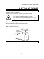
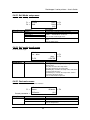
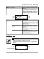
3. SETTING UP THE UNIT
3.1. UNPACKING
The unpacking procedure is described below.
The product is sent to the user in 2 boxes, 1 for the main unit and the other for the stand.
Caution :
•
•
When unpacking this product, always work with at least 4 people.
When removing this product from the packaging box, always remove the vinyl
plastic, and hold on the side of the product. Holding the unit over the vinyl plastic
wrapping can result in slippage and dropping the unit, resulting in damage.
3.1.1. Unpacking packaging box of the main unit
Unpack the package of the main unit according to the following procedure.
Step 1 :
Move the packaging of the main unit to the location to unpack.
Step 2 :
Remove the restraining bands.
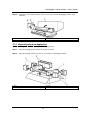
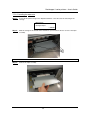
Step 3 :
Remove the top board and take out the packaging material (right upper side and left upper side).
1. Top board
3. Packaging material (left upper side)
2. Packaging material (right upper side)
31
AP-75095, Rev. 2.1, 18/08/2005
Rockhopper II series printers – User’s Guide
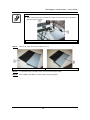
Step 4 :
Remove the outer boards and take out the accessory box and the packaging box of the waste
fluid tank.
1. Outer board
3. Packaging box of the waste fluid tank
2. Accessory box
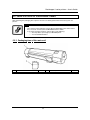
3.1.2. Unpacking stand packaging box
Unpack the package of the stand according to the following procedure.
Step 1 :
Move the packaging of the stand to the location to unpack.
Step 2 :
Open the package and take out the foot, stay and the four packaging materials.
1. Stay
3. Packaging material
2. Foot
32
AP-75095, Rev. 2.1, 18/08/2005
Rockhopper II series printers – User’s Guide
3.2. VERIFICATION OF PACKAGED ITEMS
After unpacking the packaging box, inspect if the unit is not damaged and that all necessary parts are
present.
Notes :
•
•
The contents of the packages may be different depending on the market where
they are used. Contact your local MUTOH dealer for details.
If any part is missing or broken, contact either of the following:
o The shop where you bought your MUTOH printer.
o Your local MUTOH dealer.
3.2.1. Packaging box of the main unit
1
2
Main unit
Waste fluid tank
1 set
1 set
3
33
Accessory box
1 set
AP-75095, Rev. 2.1, 18/08/2005
Rockhopper II series printers – User’s Guide
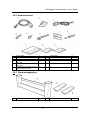
3.2.2. Accessories box
1
2
3
4
5
6
Power cable
Tube clamp
Foot switch
Hexagon socket head cap screw
(M6 x 30)
Hexagon socket head cap screw
(M6 x 16)
Assembly tool (Hexagon wrench:
diagonal diameter 5mm)
1
2
1
8
7
8
9
10
Cable clamp
Screw driver
User's Guide
Quick Start Manual
8
11
Installation sheets
2
Foot
3
1
1
1
1
3.2.3. Stand packaging box
1
Stay
1 set
34
2
AP-75095, Rev. 2.1, 18/08/2005
Rockhopper II series printers – User’s Guide
3.3. ASSEMBLY
The assembly of this product is described below.
Caution :
When assembling this product, always work with at least 4 people or more.
3.3.1. Assembling the stand
Assemble the stand according to the following procedure.
Step 1 :
Place the stand upside down as shown in the figure.
Step 2 :
2. Install the foot to the stay according to the following procedure.
A):
Attach two feet on the bottom of the stay as shown.
B):
Attach the hexagon socket head cap screws (M6 x 30: each 4) to each foot.
C):
Using the assembly tool, tighten the hexagon socket head cap screws to install the feet.
1. Stay
3. Hexagon socket head cap screw (M6 x 30)
Step 3 :
2. Foot
Assembling the stand has been completed.
35
AP-75095, Rev. 2.1, 18/08/2005
Rockhopper II series printers – User’s Guide
3.3.2. Installing the stand
Install the stand to the main unit according to the following procedure.
Step 1 :
Place the stand with its feet on the floor.
Step 2 :
Lift up the main unit with at least four persons by holding it by the handles.
Step 3 :
Place the main unit on the stand.
1. Stand
3. Handle
2. Main unit
Step 4 :
Attach the hexagon socket head cap screws (M6 x 16: 8) to the stand.
Step 5 :
Tighten the hexagon socket head cap screws to install the stand using the assembly tool.
1. Hexagon socket head cap screw (M6 x 16)
3. Main unit
Step 6 :
2. Stand
Installing the stand has been completed.
36
AP-75095, Rev. 2.1, 18/08/2005
Rockhopper II series printers – User’s Guide
3.3.3. Fixing the printer body onto the stand
After installation of the unit onto the stand, please check if there is no gap between the printer body and the
stand.
When you notice that there is a gap between the printer body and the stand, please follow the instructions
mentioned below to minimize this gap.
Notes :
Please find enclosed three types of spacers.
• 5 pieces : 0.3 mm spacer
• 5 pieces : 0.5 mm spacer
• 5 pieces : 1.0 mm spacer
Step 1 :
In case there is a gap between the stand and the printer body, loosen the screw fixing the stand
to the unit.
Step 2 :
Insert a spacer in-between the stand and the printer body.
Step 3 :
Fully insert the spacer between the stand and the printer body.
Step 4 :
Tighten the screw.
37
AP-75095, Rev. 2.1, 18/08/2005
Rockhopper II series printers – User’s Guide
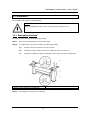
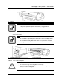
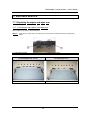
3.3.4. Removal of protective packaging material
Protective packaging material is attached on following locations of this product.
Remove all protective packaging material according to the following procedure.
Step 1 :
Remove tape from all parts of the product.
Step 2 :
Remove the two anti-rubbing materials on the top of the main unit.
1. Anti-rubbing material
Step 3 :
Remove the head unit fixture material from inside the front cover according to the following
procedure.
A):
Open the front cover.
Caution :
Be careful not to pinch your fingers when opening and closing the front cover.
1. Front cover
38
AP-75095, Rev. 2.1, 18/08/2005
Rockhopper II series printers – User’s Guide
B):
Remove the two wing bolts.
C):
Remove the head unit fixture material.
1. Wing bolt
2. Head unit fixture material
D):
Close the front cover.
1. Front cover
Step 4 :
Removal of protective packaging material is completed.
3.3.5. Installing accessories
To install accessories, such scroller receivers, take-up system, roll-off/roll-up system and waste fluid tank,
please refer to the User’s Guide “Handling roll media on a Falcon II series printer and Rockhopper II series
printer”.
Caution :
•
Before powering ON the unit, make sure the waste bottle is installed.
39
AP-75095, Rev. 2.1, 18/08/2005
Rockhopper II series printers – User’s Guide
3.4. HOW TO MAKE YOUR PRINTER OPERATIVE
The installation Eco-Solvent Plus ink cassettes for the first time into the unit is explained below.
Caution :
¾ When handling Eco-Solvent Plus ink cassettes, be careful that ink does not get in
your eyes or on your skin. However, if this happens, flush immediately with water.
Otherwise, your eyes may become congested or inflamed slightly. If you feel
discomfort, consult a doctor immediately.
¾ Do not disassemble ink cassettes. Otherwise, ink may get in your eyes or on your
skin.
¾ Only use Eco-Solvent Plus ink and appropriate Eco Solvent Plus cleaning liquid.
Using other ink (e.g. dye or pigment) could cause permanent damage to the printer.
Notes :
¾ This product has been tuned for the use of Eco-Solvent Plus ink cassettes. If other
manufacturers’ products are used,
o drawing results become faint or ink ends are not properly detected, and
o the warranty will not cover (repairs will require a fee) any resultant
breakdown.
•
Refer to the price list for the different types and details of ink cassettes.
•
Do not shake ink cassettes strongly. Otherwise, ink may leak.
•
Do not disassemble ink cassettes. You cannot use disassembled cassettes.
To install ink cassettes, follow the steps below.
Caution :
¾
Step 1 :
Before powering ON the unit, make sure to:
Remove the dummy cassettes
Remove the waste tube clamps
Remove the bag enclosing the waste tubes
Connect the waste tubes
Before powering ON the unit for the first time, please be sure to have :
¾ 8 Eco Solvent Plus cleaning cassettes (related to the requested ink configuration on the
cassette cover)
¾ 8 cassettes of Eco Solvent Plus Ink.
Caution :
•
When powering ON the unit for the first time, a cleaning cycle automatically starts.
Please follow the instructions mentioned on the display.
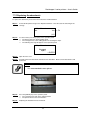
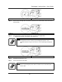
Step 2 :
Check if the Waste Bottle is empty.
Step 3 :
Power ON the unit. The display will request to insert the Cleaning Cassettes.
¾
Install the 8 NEW Eco Solvent Plus Cleaning Cassettes (related to the requested ink
configuration).
40
AP-75095, Rev. 2.1, 18/08/2005
Rockhopper II series printers – User’s Guide
1. Ink compartment
2. Ink configurations
1. Ink cassette slot
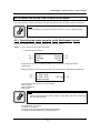
2. Cleaning cassette
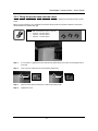
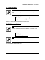
The display will show the following message.
Ink refill
rest 11 min
Please note that you have to wait 1 minute if the display mention 0 minutes.
Ink refill
rest 0 min
Step 4 :
The display will show the following message. Empty the waste Bottle.
Please empty
Waste ink tank
Step 5 :
After emptying the Waste Bottle following message will be shown. Remove all the Cleaning
Cassettes.
Please remove
cassettes
Step 6 :
After removing the Cleaning Cassettes, following messages will appear on the display.
41
AP-75095, Rev. 2.1, 18/08/2005
Rockhopper II series printers – User’s Guide
Please insert
New ink [ALL]
Step 7 :
Insert the requested configuration of Eco Solvent Plus ink cassettes.
• The ink cassette must be put in a specific slot according to the type and colour used.
• Insert the cassette with the arrow mark face-up and pointing to the rear of the printer.
• Insert the cassette as far as possible.
Step 8 :
1. Ink compartment
Step 9 :
After inserting the ink cassettes, following message will be shown.
Ink refill
rest 11 min
Please note that you have to wait 1 minute if the display mention 0 minutes.
Ink refill
rest 0 min
Step 10 : If the display shows following message, please empty the Waste ink bottle.
Please empty
Waste ink tank
Step 11 : The installation Eco-Solvent Plus ink cassettes has been finished.
Notes :
•
During ink installation, note the following.
o Do not power off the printer.
o Do not unplug the power cable.
o Do not open the front cover.
42
AP-75095, Rev. 2.1, 18/08/2005
Rockhopper II series printers – User’s Guide
3.5. INSTALLATION
Product installation is explained below.
3.5.1. Choosing a place for the printer
Install the unit on a proper location referring to the following.
Important :
•
•
•
•
Do not place the printer on a location under the following conditions. Doing
so may cause the product to fall, become damaged, or cause injury.
o Unstable surfaces
o Slanted surfaces
o Locations that are subject to vibration from other product
Do not stand on the printer or place any heavy objects on it. Doing so may
cause it to fall over, become damaged, or cause injury.
Do not cover the ventilation hole of the printer with cloth, such as a blanket
or table cloth. Doing so could prevent the printer from ventilating and cause
fire.
Keep the printer away from humid and dusty areas. Humidity may result in
electrical shock or fire.
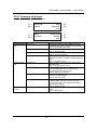
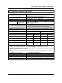
3.5.1.1. Installation environment Requirements
Choose a place for printer installation following the requirements in the table below.
50” model
64” model
87” model
Floor loading capability
Electrical
Voltage
Frequency
Capacity
Area
Environmental
Recommended
working environment
Operational conditions
Rate of change
Storage environment
11.7m² (133ft²) or larger. Frontage of 4.3m (14.3ft) or greater.
12.7m² (144ft²) or larger. Frontage of 4.7m (15.7ft) or greater.
14.3m² (162ft²) or larger. Frontage of 5.3m (17.7ft) or greater.
2490Pa (300kg/m²) or over
AC100V - 120V or AC220V – 240V
50/60Hz±1Hz
AC100V - 120V: 12A or more
AC220V - 240V: 6A or more
Temperature: 25°C
Humidity: 40% to 60%, without condensation
Temperature: 18°C to 35°C
Humidity: 40% to 60%, without condensation
Temperature: No more than 2°C per hour
Humidity: No more than 5% per hour
Temperature: -20°C to 60°C
Humidity: 5 to 85%, without condensation (When ink has
been discharged.)
Notes :
•
•
Avoid the following temperature and humidity conditions. Otherwise, printed
images may appear differently from what you expect:
o Places where sudden changes in temperature and humidity are expected,
even though the condition is within the range written above.
o Places where direct sunlight or excessive lighting are expected.
o Places where air conditioners blow directly.
MUTOH recommends that the printer should be installed where air conditioning can
be adjusted easily.
43
AP-75095, Rev. 2.1, 18/08/2005
Rockhopper II series printers – User’s Guide
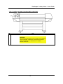
3.5.1.2. Required space
Install the product on a flat surface that fulfills the following conditions.
Notes :
•
Refer to “Product Specifications” of the User's Guide for the information of the
product.
a=1000mm b=1000mm c=2500mm d=600mm e=1250mm
3.5.2. Installing the printer
To install the product, follow the steps below.
Step 1 :
Move the product to where it will be installed.
Step 2 :
Lock the casters.
Step 3 :
Rotate the four adjusters in the direction shown in the figure to make the printer stable.
Step 4 :
Jiggle the printer to make sure that it stable.
Step 5 :
1. Adjuster
2. Caster
44
AP-75095, Rev. 2.1, 18/08/2005
Rockhopper II series printers – User’s Guide
4. PREPARING FOR A JOB
4.1. INTRODUCTION
The procedures needed before using the printer are explained below.
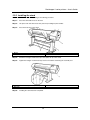
4.2. CONNECTING THE POWER CABLE
The connection procedure for the power cable is explained below.
Important :
•
•
•
Make sure that the distributed power cable is used. Use of a different cable
may result in electric shock or fire.
Do not use a damaged power cable. Doing so may result in electric shock or
fire.
The disconnect device is the plug on the power supply cord.
Caution :
•
Be careful of the following when handling the power cable.
o Do not make any modifications to the power cable.
o Do not place anything heavy on the power cable.
o Do not bend, twist, or pull the cable.
o Do not wire the cable near equipment that generates heat.
Notes :
•
If the power cable is damaged, contact one of the following :
o The shop where you bought your MUTOH printer.
o Your local MUTOH dealer.
45
AP-75095, Rev. 2.1, 18/08/2005
Rockhopper II series printers – User’s Guide
To connect the power cable, follow the steps below.
Step 1 :
Make sure the printer is off.
Notes :
•
Step 2 :
When the operation panel is in the following condition, the power is ON. Press the
key again to turn the power OFF.
o The POWER lamp is lit (green).
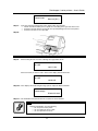
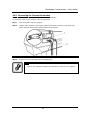
Plug the power cable to the AC inlet on the back of the printer.
1. AC inlet
2. Power cable
46
AP-75095, Rev. 2.1, 18/08/2005
Rockhopper II series printers – User’s Guide
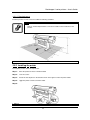
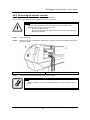
Step 3 :
Plug the cable correctly to the outlet.
Important :
•
•
•
•
•
Do not attempt to plug in electrical plugs with wet hands. Doing so may
result in electrical shock.
Be sure to use the specified voltage (AC 100V-120V/220V-240V). Otherwise,
electrical shock or fire may occur.
Use electricity directly from a power outlet (AC 100V-120V/220V-240V). Do not
put many loads on one electrical output. Otherwise, heat may be generated
and cause fire.
Be sure to use an outlet with an earth terminal, and use the terminal
correctly. Otherwise, electrical shock or fire may occur.
Do not connect earth cables in the following areas :
o Gas pipes. Doing so may cause fire or an explosion.
o Earth terminals for telephone lines or lightening rods. Doing so may
cause a large flow of voltage if lightening occurs.
o Water pipes or faucets. If there is a plastic part in the pipe, the earth
will not work correctly.
Caution :
•
•
•
Follow the instructions below when handling the power plug. Otherwise, fire may
occur.
o Wipe away dust and any other residue before inserting the plug.
o Ensure that the plug is firmly inserted as far as it will go.
Ensure that the plug has been disconnected from the power socket when it is not
used for a long time.
Earth wires must be connected to wires or terminals that fulfill the conditions :
o Earth terminals of power socket
o Earth wires with copper morsel that is at least 650 mm under ground
Notes :
•
•
If you cannot use earth terminals or find any of them, contact the shop where you
bought your printer.
Do not unplug the power cable when the printer is on. If the power cable has been
unplugged, leave the printer for at least 1 minute before plugging the cable in
again.
1. Power cable
47
AP-75095, Rev. 2.1, 18/08/2005
Rockhopper II series printers – User’s Guide
4.3. CONNECTING THE FOOT SWITCH
The connection procedure for the foot switch is described below.
If the pressure roller needs to be raised or lowered, it is possible to control this motion from the foot switch,
instead of doing so at the operation panel.
Caution :
•
When handling the foot switch, be aware of the following:
o Do not place anything heavy on the foot switch.
o Do not bend the cable of the foot switch with force and do not pull.
o Do not place the foot switch near thermal devices.
Install the foot switch according to following procedure.
Step 1 :
Make sure that the power of the unit is OFF.
Notes :
•
Step 2 :
When the operation panel is in the following condition, the power is ON. Press the
key again to turn the power OFF.
o The POWER lamp is lit (green).
Connect the foot switch cable connector to the foot switch connector at the rear of the unit and fix
into place with a screw.
1. Foot switch connector
Step 3 :
2. Foot switch cable
Place the foot switch on the floor under the stand.
1. Foot switch
48
AP-75095, Rev. 2.1, 18/08/2005
Rockhopper II series printers – User’s Guide
4.4. TURNING THE POWER ON/OFF
The method to turn the power ON or OFF is described below.
Caution :
•
Before powering ON the unit, make sure the waste bottle is installed.
4.4.1. Turning the power ON
Turn the power of the unit ON according to following procedure.
Step 1 :
Press the [POWER] key of the operation panel, to turn the unit ON.
¾ The POWER lamp of the operation panel will light (green).
Step 2 :
The unit will initial startup operations.
Step 3 :
After finishing initial startup operations, the unit will enter the normal operating condition.
Notes :
•
If there are any problems during the initial startup operation, the unit will display a
message on the operation panel, and the operation may stop. If the operation
stops, refer to "Troubleshooting", and take the appropriate actions.
4.4.2. Turning the power OFF
Turn the power of the unit OFF according to the following procedure.
Step 1 :
Verify the following regarding the operational condition of the unit.
¾ There is no printing operation being performed.
¾ The operation panel is in a normal status.
Step 2 :
Press the [POWER] key of the operation panel to turn the unit OFF.
49
AP-75095, Rev. 2.1, 18/08/2005
Rockhopper II series printers – User’s Guide
Notes :
•
Step 3 :
When the operation panel is in the following condition, the power is ON. Press the
key again to turn the power OFF.
o The POWER lamp is lit (green).
Following message is displayed for 3 seconds on the operation panel.
Notes :
•
If pressing the [POWER] key on the operation panel by mistake, press the
[POWER] key again while the following message is displayed.
Power OFF
Step 4 :
The product will perform the power OFF operation.
¾ Following message is displayed on the operation panel.
Power OFF
Please Wait
¾
¾
All lamps and the LCD of the operation panel will turn OFF.
The product will automatically turn the power OFF.
Notes :
•
If there are problems during the power OFF operation, the unit will display a
message on the operation panel, and the operation may stop. If the operation
stops, refer to “Troubleshooting” and take the appropriate actions.
50
AP-75095, Rev. 2.1, 18/08/2005
Rockhopper II series printers – User’s Guide
4.5. INSTALLING ECO-SOLVENT PLUS INK CASSETTES
The installation of Eco-Solvent Plus ink cassettes for the first time into the unit is explained below.
Caution :
•
Before powering ON the unit, make sure the waste bottle is installed.
Caution :
¾ When handling Eco-Solvent Plus ink cassettes, be careful that ink does not get in
your eyes or on your skin. However, if this happens, flush immediately with water.
Otherwise, your eyes may become congested or inflamed slightly. If you feel
discomfort, consult a doctor immediately.
¾ Do not disassemble ink cassettes. Otherwise, ink may get in your eyes or on your
skin.
¾ Only use Eco-Solvent Plus ink and appropriate cleaning liquid. Using other ink (e.g.
dye or pigment) could cause permanent damage to the printer.
Notes :
¾ This product has been tuned for the use of Eco-Solvent Plus ink cassettes. If other
manufacturer's products are used,
o drawing results become faint or ink ends are not properly detected, and
o the warranty will not cover (repairs will require a fee) any resultant
breakdown.
•
Refer to the price list for the different types and details of ink cassettes.
•
Do not shake ink cassettes strongly. Otherwise, ink may leak.
•
Do not disassemble ink cassettes. You cannot use disassembled cassettes.
To install ink cassettes, follow the steps below.
Step 1 :
Before powering ON the unit for the first time, please be sure to have :
¾ 8 cleaning cassettes (related to the requested ink configuration)
¾ 8 cassettes of the requested ink configuration
Caution :
•
Step 2 :
When powering ON the unit for the first time, a cleaning cycle should be done.
Please follow the instructions mentioned on the display.
Check if the Waste Bottle is empty.
51
AP-75095, Rev. 2.1, 18/08/2005
Rockhopper II series printers – User’s Guide
Step 3 :
Power ON the unit. The display will request to insert the Cleaning Cassettes.
¾
Install the 8 NEW Cleaning Cassettes (related to the requested ink configuration).
1. Ink compartment
1. Ink cassette slot
2. Cleaning cassette
The display will show the following message.
Ink refill
rest 8 min
Please note that you have to wait 1 minute if the display mention 0 minutes.
Ink refill
rest 0 min
Step 4 :
The display will show the following message. Empty the waste Bottle.
Please empty
Waste ink tank
Step 5 :
After emptying the Waste Bottle following message will be shown. Remove all the Cleaning
Cassettes.
Please remove
cassettes
52
AP-75095, Rev. 2.1, 18/08/2005
Rockhopper II series printers – User’s Guide
Step 6 :
After removing the Cleaning Cassettes, following messages will appear on the display.
Please insert
New ink [ALL]
Step 7 :
Insert the requested configuration of Eco-Solvent Plus ink cassettes.
1. Ink compartment
Step 8 :
After inserting the ink cassettes, following message will be shown.
Ink refill
rest 8 min
Please note that you have to wait 1 minute if the display mention 0 minutes.
Ink refill
rest 0 min
Step 9 :
If the display shows following message, please empty the Waste ink bottle.
Please empty
Waste ink tank
Step 10 : The installation of Eco-Solvent Plus ink cassettes has been finished.
Notes :
•
During ink installation, note the following.
o Do not power off the printer.
o Do not unplug the power cable.
o Do not open the front cover.
53
AP-75095, Rev. 2.1, 18/08/2005
Rockhopper II series printers – User’s Guide
4.6. MEDIA HANDLING
Media handling, attaching media, and setting media type are explained below.
4.6.1. Loading sheet media
The procedure for loading sheet media is explained below.
You can use the following sheet media with your printer.
50” model
A4 to 1273 mm max.
Width
Length
64” model
A4 to 1651 mm max.
1300 mm max.
87” model
A4 to 2240 mm max.
To load sheet media, follow the steps below.
Notes :
•
If roll media is attached to the printer, wind the media up and then load the sheet
media.
Step 1 :
Turn the printer on.
Step 2 :
The printer starts the initialize operation.
¾ The following message is displayed on the operation panel.
→ Paper End
Heaters
Cut&Feed
User1
Cleaning
Lever Up
xxxm
Notes :
•
If you do not want to use the media detection at the media initialization: Set to
"OFF" in the media detection setup item.
Step 3 :
Verify if the sheet lamp on the operation panel is unlit.
Step 4 :
Press the [F4] key on the operation panel to lower the pressure rollers.
¾ The MEDIA SET lamp will light (orange).
¾ The following message is displayed on the operation panel.
→ Please Set Paper
Heaters
Cut&Feed
User1
54
Cleaning
Lever Up
xxxm
AP-75095, Rev. 2.1, 18/08/2005
Rockhopper II series printers – User’s Guide
Notes:
•
When raising or lowering the pressurize rollers, you can use the foot switch instead
of the operation panel.
1. Foot switch
Step 5 :
Open the front cover.
Caution :
•
Be careful not to pinch your fingers when opening and closing the front cover.
1. Front cover
Step 6 :
Load the sheet media into the insertion slot at the front of the printer.
55
AP-75095, Rev. 2.1, 18/08/2005
Rockhopper II series printers – User’s Guide
1. Sheet media
Step 7 :
2. Insertion slot
Set the right edge of the media so that it is parallel with the media setting position.
Notes :
•
•
The media set position is a guideline for setting up the media.
If the right edge of the sheet media is 5 mm or more from the media setting
position, a media set error may occur if the media is not detected. Make sure to set
the right edge of the sheet media within 5 mm of the media setting position.
1. Sheet media
2. Media loading position
Step 8 :
Press the [F4] key on the operation panel to lower the pressure rollers.
¾ The MEDIA SET lamp will turn off.
Step 9 :
Close the front cover.
Notes :
•
Be careful not to pinch your fingers when opening and closing the front cover.
56
AP-75095, Rev. 2.1, 18/08/2005
Rockhopper II series printers – User’s Guide
1. Front cover
Step 10 : The media initial menu is displayed on the operation panel.
Notes :
•
To change the media type, follow the directions in "Setting media type".
* PaperInitialMenu *
F3 → LeverUp
F2, F4 → ENTER or F3
Roll ← F2
User1 ← F4
4.6.2. Loading roll media
To load roll media, please follow the instructions in the User’s Guide “Handling roll media on a Falcon II
series printer and Rockhopper II series printer”.
Notes :
•
Depending on the kind of system installed on your printer, loading media is
different.
4.6.3. Setting media type
The procedure for setting media type is explained below.
To set the media type, follow the steps below.
Step 1 :
Turn the printer on and load the media.
¾ Once the media has been set, the media initial menu will be displayed.
57
AP-75095, Rev. 2.1, 18/08/2005
Rockhopper II series printers – User’s Guide
Notes :
•
Step 2 :
Refer to following sections to load media :
o Loading media
Press one of the following keys on the operation panel, and select the current media type.
¾ When alternating roll/sheet media selection: [F2]
¾ When changing from media loading: [F3]
¾ When changing media type: [F4]
* PaperInitialMenu *
Roll ← F2
User1 ← F4
F3 → LeverUp
F2, F4 → ENTER or F3
Media type
Key
F2
Parameters
Roll media
Sheet media
Lever Down/Up
F3
Lever up
Lever down
Media Type
F4
User 1
User 2
User 3
User 4
User 5
User 6
User 7
User 8
Setup items
Step 3 :
Description
Alternates the roll media type.
• Roll media: Set when loading roll media.
• Sheet media: Set when loading sheet media.
Switches between up and down motion of the pressurizing
lever.
Use this when starting over from the media setup.
Set media type for printing.
For setup values of printing operation, eight settings of "user 18" can be set.
Refer to ‘Menu setup on the operation panel’
Press the [Enter] key on the operation panel.
¾ The media type has been set.
¾ "Media Initial" is displayed on the LCD, and the printer starts the media initial operation.
Notes :
•
The printer starts the media initial operation if you :
o Press the [CANCEL] key on the operation panel
o Leave the printer for 10 seconds without doing anything
Paper Initial
User 1
Step 4 :
When the media initial operation finishes, the printer moves to normal status.
¾ The setting media loading procedure has been completed.
Ready to print
Heaters
Cut&Feed
User1
Cleaning
Lever Up
xxxm
58
AP-75095, Rev. 2.1, 18/08/2005
Rockhopper II series printers – User’s Guide
4.7. TESTPRINTING
Follow the steps below to do a test print and confirm if your printer operates correctly.
Step 1 :
Turn the power of the unit ON, and load the media.
Step 2 :
Make sure that your printer is in normal status.
Step 3 :
Press either the [MENU ↑] key or [MENU ↓] key on the operation panel.
¾ The setup menu is displayed.
* SetupMenu *
InkStatus
F3 → TestPrint
Step 4 :
OriginSet
MediaSet
(1/6)
Press the [F3] key on the operation panel.
¾ "TestPrint: SetupPrint" is displayed on the LCD.
* TestPrint *
F1 → Setup
F3 → Adj. Uni-D
NozzleCheck ← F2
Adj. Bi-D ← F4
(1/2)
* TestPrint *
F1 → Palette
Maintenance ← F2
(2/2)
Step 5 :
Select an item and press the appropriate key.
Setup items
Test Print (1/2)
Test Print (2/2)
Key name
F1
Parameters
Setup
F2
Nozzle Check
F3
Adj. Uni-D
F4
Adj. Bi-D
F1
Palette
F2
Maintenance
Descriptions
Perform Setup List.
Refer to ‘Setup List’
Perform Nozzle check.
Refer to ‘Nozzle Check’
Perform Alignment for the uni-direction printing.
Refer to ‘Alignment’
Perform Alignment for the bi-direction printing.
Refer to ‘Alignment’
Perform Colour Palette.
Refer to ‘Colour Palette’
Perform Maintenance record.
Refer to ‘Maintenance record’
Step 6 :
Print the information on the selected item.
Step 7 :
After printing, the printer returns to the normal status.
Ready to print
Heaters
Cut&Feed
User1
Cleaning
Lever Up
xxxm
59
AP-75095, Rev. 2.1, 18/08/2005
Rockhopper II series printers – User’s Guide
4.7.1. Setup List
Use this function to check the current status of the printer.
Notes :
•
Please attach the SetupPrint data on this page.
Notes :
•
For printing, refer to the following.
o Refer to ‘Testprinting’
60
AP-75095, Rev. 2.1, 18/08/2005
Rockhopper II series printers – User’s Guide
4.7.2. NozzleCheck
Use this function to check if there is any clogging of nozzles, missing dots or faint printing.
Notes :
•
If printing quality declines, or if missing dots are evident after the NozzleCheck, the
print heads need to be cleaned. Refer to “Head cleaning" to perform head
cleaning. After finishing the head cleaning, perform the NozzleCheck again.
Notes :
•
For printing, refer to the following.
o Refer to ‘Testprinting’
4.7.3. Alignment
Use this function to adjust the print quality for best results.
Notes :
•
The print quality of your printer is pre-adjusted when it is shipped. When the
installation environment of the printer or media type has been changed and print
quality declines, use this alignment function.
To do the Alignment, follow the steps below.
Step 1 :
Turn the power of the unit ON, and set the media.
Step 2 :
Perform an accuracy adjustment printing for alignment according to "Testprinting".
¾ When performing uni-directional printing: Alignment (for the uni-direction printing)
¾ When performing bi-directional printing: Alignment (for the bi-direction printing)
Step 3 :
From the "Head A" in the printing sample, select a number in which the straight line appears with
the least blur.
61
AP-75095, Rev. 2.1, 18/08/2005
Rockhopper II series printers – User’s Guide
Step 4 :
Press either the [F2] key or [F4] key to select the number of the line you choose in the previous
step.
* HeadA (Uni-D) *
1~7
F2, F4
+ ← F2
4 - ← F4
→ ENTER
Step 5 :
Press the [Enter] key on the operation panel to register the setting value of the "Head A".
Step 6 :
Repeat the steps from 3 to 5 to register all settings followed the "Head A".
4.7.4. Colour palette
Use this function to compare the pen colour settings of the computer with the print colour of the printer.
Notes :
•
For printing, refer to the following.
o Refer to ‘Testprinting’
62
AP-75095, Rev. 2.1, 18/08/2005
Rockhopper II series printers – User’s Guide
4.7.5. Maintenance record
Use this function to check the life cycles of the printer parts.
Notes :
•
•
A part's life cycle is shown by the amount of the * mark. When a part's life cycle
comes to an end, the * mark reduces.
For printing, refer to the following. ‘Testprinting’
63
AP-75095, Rev. 2.1, 18/08/2005
Rockhopper II series printers – User’s Guide
4.8. CONNECTING THE PRINTER TO YOUR PC
How to connect the printer to your PC.
4.8.1. System requirements
To use your printer with the driver, you need a PC that fulfills the following system requirements.
System OS
CPU
Memory (RAM)
Hard disk space
Windows 2000 Professional
Pentium III 1 GHz or higher
512 MB or more
10 GB or more
Notes :
•
•
The memory requirements may vary depending on the type of applications you are
using and the complexity of the document you want to print.
MUTOH recommends you to use a hard disk and bulk memory as large as
possible.
4.8.2. Selecting cables
This printer is compatible with following interfaces:
¾ Centronics interface
¾ Network interface
The following cables are necessary to connect your printer to the computer. Prepare appropriate cables
according to the computer to be connected.
¾ Centronics interface: Centronics interface cable
¾ Network interface: 10BASE-T/100BASE-TX Ethernet cable that is compatible with both.
(Category 5)
Notes :
•
•
See below for the connection procedure.
o Refer to ‘Connecting the Centronics interface’
o Refer to ‘Connecting the network interface’
Refer to "Interface Specifications" for the connection procedure.
64
AP-75095, Rev. 2.1, 18/08/2005
Rockhopper II series printers – User’s Guide
4.8.3. Connecting the Centronics interface
The procedure for connecting the Centronics interface is explained below.
To connect the printer to your computer, follow the steps below.
Step 1 :
Turn off the printer and your computer.
Step 2 :
Plug the cable connector of the interface cable into the interface connector at the back of the
printer. Squeeze the wire clips together until they lock into place.
1. Centronics interface connector
Step 3 :
2. Interface cable
Plug the other end of the cable into the computer's port.
Notes :
•
Refer to your computer's manual for the procedure to connect to your computer.
65
AP-75095, Rev. 2.1, 18/08/2005
Rockhopper II series printers – User’s Guide
4.8.4. Connecting the network interface
The procedure for connecting the network interface is explained below.
To connect the printer to the network environment, follow the steps below.
Caution :
•
Follow the instructions below when connecting the network interface cable.
Otherwise, electrical shock or fire may occur.
o Do not touch the connector.
o Do not connect the network cable connector to the interface board having
different specifications.
Step 1 :
Turn off the printer.
Step 2 :
Plug the connector of the Ethernet cable into the connector of the network interface board at the
back of the printer.
1. Network interface connector
Step 3 :
2. Interface cable
Connect the other end of the Ethernet cable to the network.
Notes :
•
Refer to "Network interface board operation manual" to use the network interface
board.
66
AP-75095, Rev. 2.1, 18/08/2005
Rockhopper II series printers – User’s Guide
5. HANDLING THE PRINTER
5.1. INTRODUCTION
This chapter explains how to handle your printer.
5.2. DRAWING FLOW
The following flow chart illustrates the procedure for drawing with the printer.
Refer to each item as necessary.
1.
Make the printing data.
Make the printing data using an application software
2.
Turn on the printer and load media into the printer.
→ Refer to ‘Media handling’
→ Refer to ‘Using Media’
3.
Make the preference setting for drawing with the printer.
→ Refer to ‘Menu setup on the operation panel’
4.
Start printing.
→ Refer to ‘Operating from the operation panel’
→ Refer to ‘Operations after printing’
Notes :
•
Do not open the front cover during printing. Doing so may stop the printer to draw.
Though the printer resumes printing after you close the front cover, the print quality
cannot be guaranteed.
67
AP-75095, Rev. 2.1, 18/08/2005
Rockhopper II series printers – User’s Guide
5.3. USING MEDIA
This section describes details on available media for the printer.
5.3.1. Media type
The type and quality of the media affect the results of drawing enormously. Refer to the description below
and use the appropriate media for your purpose.
The following are the recommended media for the printer. Select the appropriate media for your purpose.
Notes :
•
•
For more information about the recommended media, contact your local MUTOH
dealer.
Problems that occur due to use of media other than those recommended are not
guaranteed.
Notes :
•
•
When using recommended media, the setting values for the printing quality is set
for each media type.
When printing on media other than those specified, information regarding proper
settings for the media type and settings for the product should be found on the
instructions for the media. If not contact the supplier of the media.
5.3.2. Cautions on handling media
When you handle media, please pay attention to the following.
Notes :
•
Use recommended media in an appropriate environment. Following are the
appropriate temperature and humidity ranges for printing.
Recommended working environment
Rate of change
•
•
•
•
•
•
•
Temperature
25°C
Within 2°C per hour
Humidity
40% to 60%
Within 5% per hour
Do not use creased, damaged, torn, curled, or wrapped media.
The size of the recommended sheets can change at a fixed ratio according to the
temperature changes of the working environment. Before using sheet media, place
the sheet in the working environment for at least 30 minutes, to have it match to the
temperature of the working area.
Printing before the media could accommodate to the printing environment may
cause media jams due to slippage or creases. This also adversely affects the
quality of printing.
Media has a printable side and a non-printable side. If you print on a not printable
side, blurring or slight touching may occur.
Do not touch the printable side of media. Moisture or oil from hands affects the
printing quality.
Do not leave the printer for a long time with media loaded. The media may curl
resulting in misalignment, media jams, or decreased printing quality. In particular,
avoid this in winter, dry seasons, or during final printing.
Do not lose the box or rapping bag for storing media.
68
AP-75095, Rev. 2.1, 18/08/2005
Rockhopper II series printers – User’s Guide
5.3.3. Precaution on storing media
When storing media, pay attention to the following.
Notes :
•
•
•
•
Do not store media in high temperature, high humidity, or direct sunlight.
Store sheet media in the original bag after unpacking.
Unused roll media must be removed from the scroller, rewound tightly, and stored
in the original wrapping bag and the box.
Do not wet media.
5.3.4. The printing area
The printing area is shown below.
(1) Roll media
(2) Sheet media
69
AP-75095, Rev. 2.1, 18/08/2005
Rockhopper II series printers – User’s Guide
5.3.5. Media feed compensation
Depending on the thickness of media, the media feed amount will change. Printing results may show
following symptoms:
¾ Overlapped printing images
¾ White lines on printing image, etc
For above cases, adjust media feed compensation value with following procedures.
Step 1 :
Display Media feed compensation menu on the operation panel by following "Menu setup on the
operation panel".
¾ The following messages are displayed on the operation panel.
* Dist. Adj *
F1 → Print 1
F3 → Print 2
Step 2 :
Change
Select an item and press the [F1] or [F3] Key.
Setup items
Dist. Adj.
¾
¾
Key
F1
Parameters
Print 1
F3
Print 2
Description
Perform printing by media feed compensation at ±
0.10% intervals of setup value from the current
parameter.
Perform printing by media feed compensation at ±
0.20% intervals of setup value from the current
parameter (for fine adjustment).
The following messages are displayed on the operation panel.
Print the information on the selected menu.
* Dist Adj *
Printing
→ CANCEL
Step 3 :
Confirm printing result by referring to the following figure.
70
AP-75095, Rev. 2.1, 18/08/2005
Rockhopper II series printers – User’s Guide
Step 4 :
When printing by media feed compensation has been finished, press the [CANCEL] key on the
operation panel.
¾ The following messages are displayed on the operation panel.
* Dist. Adj *
Print 1
Print 2
Change ← F2
(1/1)
Step 5 :
Press the [F2] key on the operation panel.
¾ The following messages are displayed on the operation panel.
* Change *
90.00 % - 110.00 %
F2, F4
+
110.00% → ENTER
Step 6 :
Press the [F2] or [F4] key on the operation panel to set the media feed compensation value
based on the printing result in Step 3.
Step 7 :
Press the [ENTER] key on the operation panel to confirm the setup value.
¾ The operation panel shifts to the menu of the previous hierarchy.
Step 8 :
Repeat step 2-7 until good printing result has been obtained.
Important :
•
Some RIP software by default use USER 8 media type. In this case, changing
the step adjust value might seem not to have any effect. You can overcome
this problem by first selecting USER 8 and then changing the step adjust for
USER 8.
71
AP-75095, Rev. 2.1, 18/08/2005
Rockhopper II series printers – User’s Guide
5.3.6. Details about Rockhopper II media
Eco-Solvent Plus Media List
Mutoh offers media specially targeted for outdoor applications, media aimed for indoor applications where
long-term indoor lifetime of the output is required and media specially engineered for making colourful
banners.
Together with your Rockhopper II series printer, you will receive a sample roll of one of the Mutoh EcoSolvent Plus media and a CD-ROM containing pre-ripped data, allowing you to test the Eco-Solvent Plus
media.
On the CD-rom you will find more information on how to correctly use the Eco-Solvent Plus media.
More media information, media specification sheets and free of charge media profiles for Mutoh’s in-the-box
software are at all times accessible via Mutoh’s website under http://www.mutoh.be
For pricing and availability details, please contact your Mutoh reseller.
72
AP-75095, Rev. 2.1, 18/08/2005
Rockhopper II series printers – User’s Guide
5.4. MENU SETUP ON THE OPERATION PANEL
This section describes how to make the Menu settings on the operation panel, and setup items.
Follow the steps below to make the Menu settings.
Step 1 :
Make sure that the operation panel is normal.
Ready to print
Heaters
Cut&Feed
User1
Step 2 :
Cleaning
Lever Up
xxxm
Press the [MENU↑] or [MENU↓] key.
¾ The screen shows following Menu.
Current Setup Menu → * SetupMenu *
F1 → Ink Status
F3 → TestPrint
Step 3 :
OriginSet ← F2
MediaSet ← F4
(1/7)
Set the setup menu as follows :
¾ Refer to ‘Setup menu’ – ‘Tank change menu’
Notes :
•
•
•
•
For functions of the operation panel with the setup menu displayed, refer to the
following :
o Operation panel
o Setting menu display
For the structure of the setup menu, refer to the following :
o Setup menu structure
When page numbers of the setup menu are displayed on the operation panel, you
can change the sequence by pressing the [MENU↑] or [MENU↓] key.
Each table shows the factory default settings.
73
AP-75095, Rev. 2.1, 18/08/2005
Rockhopper II series printers – User’s Guide
5.4.1. Setup menu
This section describes each setup menu of the printer.
* SetupMenu *
F1 → Ink Status
F3 → TestPrint
OriginSet ← F2
MediaSet ← F4
(1/7)
* SetupMenu *
F1 → PrintMode
F3 → Layout
Command ← F2
Function ← F4
(2/7)
* SetupMenu *
F1 → RollSetup
F3 → Network
Centro. ← F2
(3/7)
* SetupMenu *
F1 → Utility
F3 → Initial
FileMng. ← F2
(4/7)
* SetupMenu *
F1 → DataDump
InkManager ← F2
(5/7)
* SetupMenu *
F1 → CutterChg.
F3 → TankChg.
WiperClean ← F2
TubingFlush ← F4
(6/7)
* SetupMenu *
F1 → VersionCheck
(7/7)
Notes :
•
•
The Network Settings menu is displayed if the network interface board has been
installed on the product.
The items on the File Management menu are displayed if a hard disk has been
installed in the product.
74
AP-75095, Rev. 2.1, 18/08/2005
Rockhopper II series printers – User’s Guide
Setup items
Setup menu (1/7)
Parameters
Ink status
Description
Displays the information (ink status) for each ink
cassette installed in the ink cassette slot.
Refer to ‘Ink status menu’
Sets the printing start position (origin) for printing
data.
Refer to ‘Origin setup menu’
Performs test printing.
Refer to ‘Test print menu’
Makes various media settings.
Refer to ‘Media setup menu’
Makes various print mode settings.
Refer to ‘Printing mode menu’
Makes various printer commands settings.
Refer to ‘Command setup menu’
Makes various layout function settings.
Refer to ‘Layout setup menu’
Makes various processing printing data settings.
Refer to ‘Function setup menu’
Makes various roll media settings.
Refer to ‘Roll Media setup menu’
Sets Centronics Interface communication mode.
Refer to ‘Centronics menu’
Makes the settings for the network interface.
Refer to ‘Network setting menu’
Makes various advanced function settings.
Refer to ‘Utility menu’
Makes various settings for the processing method of
the printing data sent from computer to the installed
hard disk in the printer.
Refer to ‘File management setup menu’
Returns the parameters to factory default value.
Refer to ‘Initialize setup menu’
The dump printing for the online feature check will be
performed.
Refer to ‘Data dump menu’
Perform ‘HeadWash’, ‘InkChange’ or ‘InkLoad’.
Refer to ‘Ink Manager menu’
The cutting blade is replaced.
Refer to ‘Cutter change menu’
Clean the wiper.
Refer to ‘Wiper clean menu’
Tank is replaced.
Refer to ‘Tank change menu’
Makes various tubing flush settings
Refer to ‘Tubing flush menu”
Ability to view the installed firmware version.
Refer to ‘Version Check’
Origin setting
Test print
Media setting
Setup menu (2/7)
Print mode setting
Command setting
Layout setting
Function setting
Setup menu (3/7)
Roll media setting
Centronics setting
Network setting
Setup menu (4/7)
Utility setting
File management setting
Initialize setting
Setup menu (5/7)
Data dump
Ink Manager
Setup menu (6/7)
Cutting blade replacement
Wiper cleaning
Tank replacement
Tubing Flush
Version Check
Setup menu (7/7)
Setup menu (1/77/7)
-
[CANCEL] key: Cancel the setup menu, and shift to
the normal condition.
Notes :
•
By using the software server RIP (option), some setups for printing can be set by
the RIP. For details, refer to the operation manual of the products.
75
AP-75095, Rev. 2.1, 18/08/2005
Rockhopper II series printers – User’s Guide
5.4.2. Ink status menu
Displays the information (ink status) for each ink cassette installed in the ink cassette slot.
* InkStatus *
K : + 100 C: +100 W : X 100
W : X 100 Y : + 100 M : + 100
C : + 100 m : + 100
Eco+
Setup items
Ink Status
Parameters
Ink status for the ink cassette
slots 1 – 8.
Description
• Display
¾ Line 2: ink cassette slots 1 – 3
¾ Line 3: ink cassette slots 4 – 6
¾ Line 4: ink cassette slots 7 - 8
• Symbols
¾
Ink Colour: K : Black, C : Cyan, M :
Magenta, Y : Yellow, c : Light Cyan,
m : Light Magenta, W = Cleaning
Liquid
¾
Type of Ink:
ECO + = Eco-Solvent Plus
X = Cleaning Cassette
ECOMIX = Eco-Solvent
mixed with Eco-Solvent Plus
¾
Ink Remaining: 0 - 100(%)
• mode : in the lower right corner (e.g. Eco+)
-
[CANCEL] key: shift to the previous hierarchy menu.
Refer to ‘Setup menu’
Notes :
•
To display the Ink Status menu, be sure to use the recommended ink cassettes. If
any other ink cassette is used, the ink status will not be correctly displayed.
76
AP-75095, Rev. 2.1, 18/08/2005
Rockhopper II series printers – User’s Guide
5.4.3. Origin setup menu
Sets the printing start position (origin) for printing data.
Set this when you want to re-print to blank area of the printed media by changing the layout of the printing
data.
* Origin *
F1 → Forward
F3 → Back
Parameter → L : 00500.0
Setup items
Origin setting
Left ← F2
Right ← F4
W : 01000.0
Parameters
• L: Media feed value
• W: Print head movement
value
(Unit: mm)
Description
Changes the print head position and media feed
amount by operating the following keys.
• [F1] key: Feeds media forward.
• [F2] key: Moves the print head to the left.
• [F3] key: Feeds media backward.
• [F4] key: Moves the print head to the right.
• [ENTER] key: Determines the setup values then
returns to the previous hierarchical menu. Refer to
‘Setup menu’
-
[CANCEL] key: shifts to the previous hierarchy menu.
Refer to ‘Setup menu’
Notes :
•
When printing from the data on the hard disk, the printing will start from the same
start position as when the printing data was written, regardless of the home position
setting value.
Notes :
•
The origin setup menu automatically ends without pressing any key for a certain
period, to avoid drying the print head.
77
AP-75095, Rev. 2.1, 18/08/2005
Rockhopper II series printers – User’s Guide
5.4.4. Test print menu
Perform Test print.
* TestPrint *
F1 → Setup
F3 → Adj. Uni-D
NozzleCheck ← F2
Adj. Bi-D ← F4
(1/2)
* TestPrint *
F1 → Palette
Maintenance ← F2
(2/2)
Setup items
Test print (1/2)
Parameters
SetupPrint
Description
Performs setup printing.
Refer to ‘Setup List’
Performs nozzle check printing.
Refer to ‘NozzleCheck’
Performs accuracy adjustment printing in one
direction.
Refer to ‘Alignment’
Performs accuracy adjustment printing in two
directions.
Refer to ‘Alignment’
Performs pallet printing.
Refer to ‘Colour palette’
Maintenance status printing is performed.
Refer to ‘Maintenance record’
[CANCEL] key: shift to the previous hierarchy menu.
Refer to ‘Setup menu’
NozzleCheck
Alignment (UniDir)
Alignment (BiDir)
Test print (2/2)
Pallet printing
Maintenance status
Test print (1/22/2)
-
78
AP-75095, Rev. 2.1, 18/08/2005
Rockhopper II series printers – User’s Guide
5.4.5. Media setup menu
Perform various settings for media.
* MediaSet *
F1 → Media
F3 → TopFeed
Setup items
Media setting
CutSize ← F2
MediaCut ← F4
(1/1)
Parameters
Type
Description
Sets the media type used for test printing.
Refer to ‘Media type menu’
To set the method for detecting the size of the media
when sheet media has been loaded.
Refer to ‘Cut size menu’
Sets the amount of media to be fed when printing
begins. Make this setting when using roll media.
Refer to ‘Top feed menu’
The method of cutting the media after printing is set
here.
Refer to ‘Media cut menu’
[CANCEL] key: to shift to the previous hierarchy
menu.
Refer to ‘Setup menu’
Cut size
Top feed
Media cutting
-
5.4.6. Media type menu
Set media type for printing.
* SetupMenu *
F1 → User 1
F3 → User 3
User 2 ← F2
User 4 ← F4
(1/2)
* SetupMenu *
F1 → User 5
F3 → User 7
Setup items
Types (1/2)
Types (2/2)
Type (1/2-2/2)
User 6 ← F2
User 8 ← F4
(2/2)
Parameters
User media 1
User media 2
User media 3
User media 4
User media 5
User media 6
User media 7
User media 8
-
Description
To set the type of media used for printing.
For setup values of printing operation, eight settings
of "user media 1-8" can be set.
Refer to ‘User media menu’
[CANCEL] key: to shift to the previous hierarchy
menu.
Refer to ‘Media setup menu’
79
AP-75095, Rev. 2.1, 18/08/2005
Rockhopper II series printers – User’s Guide
5.4.7. User media menu
Makes various settings on user defined media.
In the User media menu, for each setup value of following printing operation, eight settings of "user media 18" can be set.
Notes :
When media other than the recommended media are used (user media), the following
problems may occur :
¾ Media detection error
¾ Oblique, torn, and creased media
¾ Media jams
¾ Decrease in print quality due to blurring, missing, or smudging of ink
¾ End detection error of roll media
Problems caused by using media other than the recommended will void the warranty.
For more information, contact your local MUTOH dealer.
5.4.7.1. User media menu Rockhopper II
* User 1 *
F1 → ThinOut
F3 → HeadHeight
InkDryTime ← F2
Stiff ← F4
(1/3)
* User 1 *
F1 → Thick
F3 → Drier
Heater ← F2
HStatus ← F4
(2/3)
* User 1 *
F1 → Dist. Adj
(3/3)
Setup items
User media 1-8
(1/3)
Parameters
Amount of ink
InkDryTime
HeadHeight
Stiff
User media 1-8
(2/3)
Thickness
Heater
Drier
HStatus
User media 1-8
(3/3)
Dist.Adj
Description
Sets the amount of ink discharged while printing according to the
media type. → Refer to ‘Ink amount menu’
In order to let the ink for the printing dry, the time between the end of
the print and the beginning of the next print is set. → Refer to ‘InkDry
menu’
Sets the distance (head height) between the print head and the
media. → Refer to ‘Head Height menu’
Makes the setting for the absorbing power of the media to the printing
board depending on the hardness of the media. → Refer to ‘Stiff
menu’
Makes the setting on the width of the media to be used. → Refer to
‘Thickness menu’
Sets the temperature of the Heater. → Refer to ‘Heater Menu’
Sets the temperature of the Drier. → Refer to ‘Drier Menu’
Checks the temperature of Heater and Drier. → Refer to ‘HStatus
Menu’
Performs various settings for media feed compensation. → Refer to
‘Media feed compensation menu’
80
AP-75095, Rev. 2.1, 18/08/2005
Rockhopper II series printers – User’s Guide
5.4.7.2. User media menu Rockhopper II 4H
* User 1 *
F1 → ThinOut
F3 → HeadHeight
InkDryTime ← F2
Stiff ← F4
(1/3)
* User 1 *
F1 → Thick
F3 → Drier
Heater ← F2
Fixer ← F4
(2/3)
* User 1 *
F1 → Post Fixer
F3 → Dist. Adj
HStatus ← F2
(3/3)
Setup items
User media 1-8
(1/3)
Parameters
Amount of ink
InkDryTime
HeadHeight
Stiff
User media 1-8
(2/3)
Thickness
Heater
User media 1-8
(3/3)
Drier
Fixer
Post Fixer
HStatus
Dist.Adj
Description
Sets the amount of ink discharged while printing according
to the media type. → Refer to ‘Ink amount menu’
In order to let the ink for the printing dry, the time between
the end of the print and the beginning of the next print is set.
→ Refer to ‘InkDry menu’
Sets the distance (head height) between the print head and
the media. → Refer to ‘Head Height menu’
Makes the setting for the absorbing power of the media to
the printing board depending on the hardness of the media.
→ Refer to ‘Stiff menu’
Makes the setting on the width of the media to be used. →
Refer to ‘Thickness menu’
Sets the temperature of the Heater. → Refer to ‘Heater
Menu’
Sets the temperature of the Drier. → Refer to ‘Drier Menu’
Sets the temperature of the Drier. → Refer to ‘Fixer Menu’
Sets the temperature of the Drier. → Refer to ‘Post Fixer
Menu’
Checks the temperature of heating elements. → Refer to
‘HStatus Menu’
Performs various settings for media feed compensation. →
Refer to ‘Media feed compensation menu’
81
AP-75095, Rev. 2.1, 18/08/2005
Rockhopper II series printers – User’s Guide
5.4.8. Thin Out: Ink amount menu
Sets the amount of ink discharged while printing, according to the media type.
* ThinOut *
50% - 100%
+ ← F2
100% - ← F4
→ ENTER
F2, F4
Setup items
Amount of ink
Parameters
50 %-< 100%>
Description
Use the following keys to change the amount of ink.
• [F2] key: Increases the setting value.
• [F4] key: Reduces the setting value.
• [ENTER] key: Sets the setting value, and moves the
screen to the menu of the previous hierarchy.
• [CANCEL] key: Cancels the setting value, and
moves the screen to the menu of the previous
hierarchy.
Refer to ‘User media menu’
5.4.9. InkDry menu
Sets the waiting period between the end of operation and the start of next printing in order to let the printed
media dry.
* InkDryTime *
0 sec – 60 min
+ ← F2
30 sec - ← F4
→ ENTER
F2, F4
Setup items
InkDryTime
Parameters
0 to <30 sec. > to 270 sec. to
60 min.
82
Description
To change the InkDryTime by operating the following
keys.
• [F2] key: Increases the setup value.
• [F4] key: Decreases the setup value.
• [ENTER] key: Confirms the setup value, shifts to the
previous hierarchy menu.
• [CANCEL] key: Cancels the setup value, shifts to
the previous hierarchy menu.
Refer to ‘User media menu’
AP-75095, Rev. 2.1, 18/08/2005
Rockhopper II series printers – User’s Guide
5.4.10. Head Height menu
Sets the distance (head height) between the print head and the media.
Head height can be changed to three levels according to media thickness.
* HeadHeight *
F1 → Low
F3 → High
Current parameter → - low Setup items
HeadHeight
Parameters
Low
Middle ← F2
(1/1)
Description
Make this setting when using media with a thickness
of 80µm (0.08mm) to 300µm (0.3mm).
Make this setting when using media with a thickness
of 300µm (0.3mm) to 700µm (0.7mm).
Make this setting when using media with a thickness
of 700µm (0.7mm) to 1000µm (1.0mm).
Refer to ‘User media menu’
Middle
High
Notes :
•
Set the height of the head in relation to the thickness of the media.
o If the setting is set to "High" and the print is created on thin media, good
quality print results will not be achieved.
o If the setting is set to "Low" and thick media is used, the media and print
head will come into contact and may result in damage to the product.
5.4.11. Stiff menu
Sets the media sticking force (media stiffness) to the media guide.
* Stiff *
F1 → Soft
Normal ← F2
Current parameter → - Normal Setup items
Stiff
(1/1)
Parameters
<Normal>
Soft
Description
Setting for normal media
Setting for soft media where media feeding errors
and media jams occur
After setting, shift to the previous hierarchy menu.
Refer to ‘User media menu’
-
83
AP-75095, Rev. 2.1, 18/08/2005
Rockhopper II series printers – User’s Guide
5.4.12. Thickness menu
Sets the media thickness.
* Thick *
50 µm – 1500 µm
F2, F4
Setup items
Thickness
Parameters
50µm-<100µm>-1500µm
+ ← F2
100 µm - ← F4
→ ENTER
Description
Change media thickness by operating the following
keys.
• [F2] key: to increase the setup value.
• [F4] key: to decrease the setup value.
• [ENTER] key: to confirm the setup value and to shift
to the previous hierarchy menu.
• [CANCEL] key: to cancel the setup value and to
shift to the previous hierarchy menu.
Refer to ‘User media menu’
5.4.13. Heater menu
Sets the temperature of the Heater.
* Heater (A) *
OFF – 50°C
+ ← F2
50°C - ← F4
→ ENTER
F2, F4
Use the [F2] or [F4] key to select the requested temperature for the Heater.
Notes :
•
•
The default setting for the heater is set to ‘50°C’.
The function of the heater (A) : Warming the transfer paper before entering the
pressure rollers. The pre-expansion helps to minimize media cockling.
Caution :
•
We recommend you to set the pre-heater temperature at 50°C. This to be sure that
transfer paper is already expanded a little before reaching the pressure rollers.
84
AP-75095, Rev. 2.1, 18/08/2005
Rockhopper II series printers – User’s Guide
5.4.14. Drier menu
Set the temperature of the Drier.
* Drier (D) *
OFF – 50°C
+ ← F2
50°C - ← F4
→ ENTER
F2, F4
Use the [F2] or [F4] key to select the requested temperature for the Drier.
Notes :
•
•
The default setting for the drier is set to ‘50°C’.
The function of the drier (D) : Heating the printed transfer paper evaporates the
water fast enough so that the print is touch-dry when wound.
Caution :
•
We recommend you to set the dryer temperature at 50°C. This to be sure that
transfer paper is touch-dry when wound.
5.4.15. Fixer menu
Set the temperature of the Fixer.
Notes :
Please note that this heating element is only available onto the Rockhopper II 4H series
printer.
* Fixer (B) *
OFF – 70°C
+ ← F2
70°C - ← F4
→ ENTER
F2, F4
Use the [F2] or [F4] key to select the requested temperature for the Fixer.
85
AP-75095, Rev. 2.1, 18/08/2005
Rockhopper II series printers – User’s Guide
5.4.16. Post Fixer menu
Set the temperature of the Post Fixer.
Notes :
Please note that this heating element is only available onto the Rockhopper II 4H series
printer.
* Post Fixer (C) *
OFF – 70°C
F2, F4
+ ← F2
70°C - ← F4
→ ENTER
Use the [F2] or [F4] key to select the requested temperature for the Post Fixer.
5.4.17. HStatus menu Rockhopper II
Check the temperature of the heating elements.
Notes :
Please note that this heating element is only available onto the Rockhopper II series
printer.
* HStatus *
A: 27 D : 29
Heating NOT Ready
Notes :
A stands for the Heater.
D stands for the Dryer.
Press the [CANCEL] key to go to the previous menu.
86
AP-75095, Rev. 2.1, 18/08/2005
Rockhopper II series printers – User’s Guide
5.4.18. HStatus menu Rockhopper II 4H
Check the temperature of the heating elements.
Notes :
Please note that this heating element is only available onto the Rockhopper II 4H series
printer.
* HStatus *
A: 49 B: 26 C: 27
Heating NOT Ready
D : 49
Notes :
A stands for the Heater.
B stands for the Fixer.
C stands for the Post Fixer.
D stands for the Dryer.
Press the [CANCEL] key to go to the previous menu.
5.4.19. Media feed compensation menu
To perform various settings for media feed compensation
Notes :
•
For details of the media feed compensation, refer to "Media feed compensation".
* Dist. Adj *
F1 → Print 1
F3 → Print 2
Change ← F2
(1/1)
Setup items
Dist.Adj
Parameters
Print1
Change
Description
Performs printing by media feed compensation.
A correction pattern with a width of ± 0.20% (in steps of 0.10 %) is
printed around the center of the correction value currently set.
Refer to ‘Printing by Media feed compensation menu’
Changes the media feed compensation value.
The menu changes to the Change Media Feed Correction Value menu.
Refer to ‘Change media feed compensation value menu’
87
AP-75095, Rev. 2.1, 18/08/2005
Rockhopper II series printers – User’s Guide
Print2
Performs printing by media feed compensation (for fine adjustment).
A correction pattern with a width of ± 0.02% (in steps of 0.01%) is
printed around the center of the correction value currently set.
Refer to ‘Printing by Media feed compensation menu’
[CANCEL] key: Shifts to the previous hierarchy menu.
Refer to ‘User media menu’
-
5.4.20. Change media feed compensation value menu
Changes the media feed compensation value.
* Change *
90.00% - 110.00%
F2, F4
Setup items
Change
Parameters
90.00%-<100.00%>-110.00%
+ ← F2
110.00% - ← F4
→ ENTER
Description
Changes the media feed compensation value by
operating the following keys.
• [F2] key: to increase the setup value.
• [F4] key: to decrease setup value.
• [ENTER] key: Confirm setup value, shift to the
previous hierarchy menu.
• [CANCEL] key: Cancel setup value, shift to the
previous hierarchy menu.
Refer to ‘Media feed compensation menu’
5.4.21. Printing by Media feed compensation menu
Performs printing by media feed compensation.
* Dist. Adj *
Printing
→ CANCEL
Setup items
Dist.Adj
Parameters
Data printing
Description
Now printing by media feed compensation. Wait for a
while until printing has been finished.
• [CANCEL] key: to perform following operations :
• Media feed correction printing has been finished.
• to eject media.
• to shift to the previous hierarchy menu.
Refer to ‘Media feed compensation menu’
-
88
AP-75095, Rev. 2.1, 18/08/2005
Rockhopper II series printers – User’s Guide
5.4.22. Cut size menu
When setting sheet media in the tray, set the method for detecting the size of the media.
* CutSize *
F1 → Auto
F3 → Width
Current parameter → - Length Setup items
Cut Size
Length ← F2
(1/1)
Parameters
<Auto>
Description
The length and width of the sheet media is
automatically detected.
Make this setting when placing normal size sheet
media vertically on the tray.
Make this setting when placing normal size sheet
media horizontally on the tray.
After setting, shift to the previous hierarchy menu.
Refer to ‘Media setup menu’
Length
Width
-
Notes :
•
•
When using sheet media other than recommended media, set to "blank form
vertical" or "blank form horizontal".
The following size of sheet media can be set.
o ISO series (A0, A1, A2, A3, A4)
o JIS series (B1, B2, B3, B4)
o ARCH series (A, B, C, D)
5.4.23. Top feed menu
Sets the amount of media to be fed when printing begins. Make this setting when using roll media.
* TopFeed *
0 mm – 400 mm
F2, F4
Setup items
Top feed
Parameters
<0mm>-400mm
+ ← F2
0 mm - ← F4
→ ENTER
Description
To feed media at the start of printing. Set when
printing on roll media.
• "F2" key: Increases the setting value.
• "F4" key: Reduces the setting value.
• "ENTER" key: Sets the setting value, and moves
the screen to the menu of the previous hierarchy.
• [CANCEL] key: Cancels the setup value and shifts
to the previous hierarchy menu.
Refer to ‘Media setup menu’
89
AP-75095, Rev. 2.1, 18/08/2005
Rockhopper II series printers – User’s Guide
5.4.24. Media cut menu
Set media cut method after printing.
* MediaCut *
F1 → Off
F3 → Manual
Current Parameter → - Auto Setup items
Media cutting
Auto ← F2
(1/1)
Parameters
Auto
Description
After printing has been completed, the media is sent
to the media cut position and is automatically cut.
Refer to ‘Cutting media’
Feed media to the media cut position after printing.
Use regular cutting blades available from hardware
stores.
Refer to ‘Media cutting procedure’
No media feed after printing.
When "ALL" is selected, proceed to the Shortest Cut
Length menu.
Refer to ‘Shortest cut menu’
• If "Manual" or "Off" has been selected, the screen
changes to the menu of the previous hierarchy.
Refer to ‘Media setup menu’
Manual
Off
-
Notes :
•
•
For the situations shown below, the media cut settings are always changed to "Off"
regardless the previous settings.
o When "Take-up system" or “Roll-up/roll off system” is set for the media
detection settings (Media detection menu)
When using the media shown below, set the media cut setting to "Manual". If set to
"Auto", the following errors may occur :
o Cloth material: The cloth fiber is not completely cut.
o Media with glue: Glue will adhere to the cutting blade and decrease cutting
performance.
5.4.25. Shortest cut menu
To set the minimum page length for cutting media. (Only in the “Media Cutting → Auto”-menu available)
* ShortestCutPaper *
100 mm – 700 mm
F2, F4
Setup items
Shortest Cut
Paper
Parameters
<100mm>-700mm
+ ← F2
100 mm - ← F4
→ ENTER
Description
To set the shortest length of the media when cutting
• [F2] key : Increases the setting value.
• [F4] key : Reduces the setting value.
• [ENTER] key : Sets the setting value, and moves
the screen to the menu of the previous hierarchy.
• [CANCEL] key: Cancels the setup value, shift to the
previous hierarchy menu.
Refer to ‘Media setup menu’
90
AP-75095, Rev. 2.1, 18/08/2005
Rockhopper II series printers – User’s Guide
5.4.26. Printing mode menu
To perform various settings for Printing mode.
* PrintMode *
F1 → PrnMode1
F3 → PrnMode3
Setup items
Print mode setup
PrnMode2 ← F2
PrnMode4 ← F4
(1/1)
Parameters
Print mode 1
Print mode 2
Print mode 3
Print mode 4
-
Description
For each setup value of Printing mode, four settings
of "Printing mode 1" - "Printing mode 4" can be set.
Refer to ‘Printing mode setup menu’
[CANCEL] key: to shift to the previous hierarchy
menu.
Refer to ‘Setup menu’
5.4.27. Printing mode setup menu
To perform various settings for Printing mode.
For each setup value of Printing mode, four settings of "Printing mode 1" - "Printing mode 4" can be set.
* PrnMode1 *
F1 → ColourMode
F3 → Direction
Condition ← F2
RepeatPrn. ← F4
(1/2)
* PrnMode1 *
F1 → HeadSpeed
(2/2)
Setup items
Printing mode 1-4
(1/2)
Parameters
Colour mode
Description
To set the number of colours used for printing.
Refer to ‘Colour mode menu’
To set printing quality.
Refer to ‘Printing quality menu’
To set print head moving direction for printing.
Refer to ‘Printing direction menu’
To make settings for the repeat print.
Refer to ‘Repeat printing menu’
To set the head speed
Refer to ‘Head speed menu’
[CANCEL] key: To shift to the previous hierarchy
menu.
Refer to ‘Setup menu’
Printing condition
Printing direction
Repeat printing
Printing mode 1-4
(2/2)
Printing mode 1-4
Head speed
-
91
AP-75095, Rev. 2.1, 18/08/2005
Rockhopper II series printers – User’s Guide
5.4.28. Colour mode menu
To check the current ink cassette colour mode.
[CANCEL] key: to shift to the previous hierarchy menu.
Please find below an example.
* ColorMode *
6 Col. LcLm
- 6 Col. LcLm -
(1/1)
5.4.29. Printing quality menu
To set printing quality.
Select printing quality with consideration to applications of printing data and printing speed.
F1 →
F3 →
Current parameter →
* Condition *
360 x 360
360 x 720
- 360 x 360 -
720 x 360
Diag720
(1/4)
← F2
← F4
F1 →
F3 →
Current parameter →
* Condition *
720 x 720
1440 x 720
- 360 x 360 -
1080 x 1080
720 x 1440
(2/4)
← F2
← F4
F1 →
F3 →
Current parameter →
* Condition *
Diag1440
2160 x 1080
- 360 x 360 -
1440 x 1440
1080 x 2160
(3/4)
← F2
← F4
F1 →
F3 →
Current parameter →
* Condition *
Diag2160
1440 x 2880
- 360 x 360 -
2880 x 1440
Diag2880
(4/4)
← F2
← F4
Setup items
Condition (1/4)
Condition (2/4)
Condition (3/4)
Condition (4/4)
Condition (1/4 –
4/4)
Parameters
<360 × 360dpi>
720 × 360dpi
360 × 720dpi
Diagonal 720dpi
720 × 720dpi
1080 × 1080dpi
1440 × 720dpi
720 × 1440dpi
Diagonal 1440dpi
1440 × 1440dpi
2160 × 1080dpi
1080 × 2160dpi
Diagonal 2160dpi
2880 × 1440dpi
1440 × 2880dpi
Diagonal 2880dpi
-
Description
The display changes to interlace setup items after the print
quality items settings have been finished.
Refer to ‘InterLace Setup menu’
[CANCEL] key: To shift to the previous hierarchy menu.
Refer to ‘Printing mode setup menu’
92
AP-75095, Rev. 2.1, 18/08/2005
Rockhopper II series printers – User’s Guide
5.4.30. InterLace Setup menu
To set the over printing method (interlace method) for printing.
* Interlace *
F1 → 1pass
F3 → 2pass
Current parameter → - 1pass Setup items
Interlace method
1passFew ← F2
4pass ← F4
(1/1)
Parameters
1 pass
1 pass Few
2 pass
4 pass
-
Description
Over printing is not performed.
Only gaps between lines are overwritten.
Over-printing is performed twice per 1 line.
Over-printing is performed four times per 1 line.
[CANCEL] key: To shift to the previous hierarchy
menu.
Refer to ‘Setup menu’
5.4.31. Printing direction menu
To set print head moving direction for printing.
* Direction *
F1 → UniDir.
BiDir. ← F2
Current parameter → - BiDir. Setup items
Direction
(1/1)
Parameters
UniDir
BiDir
-
Description
Prints in one direction.
Prints bi-directionally.
[CANCEL] key: To shift to the previous hierarchy
menu.
Refer to ‘Setup menu’
5.4.32. Repeat printing menu
To make settings for the repeat print.
* RepeatPrn *
F1 → Count
IntervalTime ← F2
(1/1)
Setup items
Repeat
Parameters
Times
Description
To set the number of repeats per line of printing.
Refer to ‘Repeat times menu’
To set interval time for the repeat print.
Refer to ‘Interval time menu’
[CANCEL] key: To shift to the previous hierarchy
menu.
Refer to ‘Setup menu’
Interval
-
93
AP-75095, Rev. 2.1, 18/08/2005
Rockhopper II series printers – User’s Guide
5.4.33. Repeat times menu
To set the number of repeats per line of printing.
* Count *
1 cnt – 99 cnt
+ ← F2
1 cnt - ← F4
→ ENTER
F2, F4
Setup items
Times
Parameters
<Once> to 99 times
Description
To change repeat times by operating the following
keys:
• [F2] key: Increases the setup value.
• [F4] key: Decreases the setup value.
• [ENTER] key: To confirm the setup value, to shift to
the previous hierarchy menu.
• [CANCEL] key: To cancel setup value, to shift to the
previous hierarchy menu.
Refer to ‘Repeat printing menu’
5.4.34. Interval time menu
To set interval time for the repeat print.
* IntervalTime *
0.0 sec – 5.0 sec
F2, F4
Setup items
Interval
Parameters
<0.0 sec.> to 0.1 to 5.0 sec.
+ ← F2
0.0 sec - ← F4
→ ENTER
Description
To change interval time by operating the following
keys.
• [F2] key: Increases the setup value.
• [F4] key: Decreases the setup value.
• [ENTER] key: Confirms the setup value, shift to the
previous hierarchy menu.
• [CANCEL] key: Cancels the setup value, shifts to
the previous hierarchy menu.
Refer to ‘To repeat the printing menu’
5.4.35. Head speed menu
To set the head speed
* HeadSpeed *
F1 → Normal
Fine ← F2
-NormalSetup items
HeadSpeed
(1/1)
Parameters
Normal
Fine
-
Description
Print at normal speed
Print at half speed.
[CANCEL] key: To shift to the previous hierarchy
menu.
Refer to ‘Setup menu’
94
AP-75095, Rev. 2.1, 18/08/2005
Rockhopper II series printers – User’s Guide
5.4.36. Command setup menu
To perform various settings for printer commands.
* Command *
F1 → Command
F3 → Position
Step ← F2
Terminator ← F4
(1/2)
* Command *
F1 → Resolu.
F3 → Overwrite
Setup items
Command setup
(1/2)
OnlineTimer ← F2
Halftone ← F4
(2/2)
Parameters
Command
Description
To make the settings for the conditions of printer
commands sent from the computer to the product.
Refer to ‘Command select menu’
To set the units for amount of movement for printing.
Refer to ‘Print step menu’
To set the initial writing position for printing.
Refer to ‘Print position menu’
To set the functions for when printing has been
completed for printer commands included in printing
data.
Refer to ‘Terminator menu’
Makes settings for image resolution while printing
with image data.
Refer to ‘Image resolution menu’
Makes settings for the time between the end of
receiving printing data from a computer and
recognizing the end of printing data.
Refer to ‘Online time out menu’
Sets the printing method for areas where figures
overlap on the printing data.
Refer to ‘Overwrite menu’
When creating prints of MH-GL/GL2 (vector) data
and RTLPASS (raster) data that have not been
converted into binary, set the gradation sequence
representation method.
Refer to ‘Halftone menu’
[CANCEL] key: to shift to the previous hierarchy
menu.
Refer to ‘Setup menu’
Step
Position
Terminator
Command setup
(2/2)
ImageResolu
OnlineTimer
Overwrite
Halftone
Command setup
(1/2-2/2)
-
95
AP-75095, Rev. 2.1, 18/08/2005
Rockhopper II series printers – User’s Guide
5.4.37. Command select menu
To make the settings for the conditions of printer commands sent from the computer to the printer.
* Command *
F1 → ML – GL. GL2
F3 → RTL – PASS
Current parameter → - RTL –PASS Setup items
Command
Parameters
MH-GL, GL2
MH-GL2
<RTL-PASS>
-
ML – GL2 ← F2
(1/1)
Description
To set to MH-GL, GL2.
To set to MH- GL2.
To set to RTL-PASS.
To shift to the previous hierarchy menu.
Refer to ‘Command setup menu’
5.4.38. Print step menu
To set the units for amount of movement for printing.
* Step *
F1 → 0.010 mm
0.025 mm ← F2
Current parameter → - 0.010 mm Setup items
Print step
(1/1)
Parameters
<0.010mm>
<0.025mm>
-
Description
To set the printing units to 0.010mm.
To set the printing units to 0.025mm.
To shift to the previous hierarchy menu.
Refer to ‘Command setup menu’
Notes :
Please note that some software packages use the “step per mm” terminology, in which
case a program step of 0.025 mm corresponds with 40 steps per mm and a program
step of 0.010 mm with 100 steps per mm.
5.4.39. Print position menu
To set the initial writing position for printing.
* Position *
F1 → P1
F3 → Full
Current parameter → - P1 Setup items
Print position
LL ← F2
(1/1)
Parameters
<P1>
LL
Full
-
Description
To set the initial location of the scaling point.
To set the lower left position of the hard clip.
To set the lower left position of the media.
To shift to the previous hierarchy menu.
Refer to ‘setup menu’
96
AP-75095, Rev. 2.1, 18/08/2005
Rockhopper II series printers – User’s Guide
5.4.40. Terminator menu
To set the functions for when printing is complete for printer commands included in printing data.
* Terminator *
F1 → Normal
Special ← F2
Current parameter → - Normal Setup items
Terminator
(1/1)
Parameters
Normal
<Special>
Description
This is used only for printer command functions.
The SP0 ;( SP ;) command is recognized as the end
of the data.
To shift to the previous hierarchy menu.
Refer to ‘Command setup menu’
-
5.4.41. Image resolution menu
To set resolution for image data for printing.
* Resolu. *
F1 → 360dpi
F3 → 720dpi
Current parameter → - 360dpi -
600dpi ← F2
1080dpi ← F4
(1/2)
* Resolu. *
F1 → 1200dpi
F3 → 2160dpi
Current parameter → - 360dpi -
1440dpi ← F2
2880dpi ← F4
(2/2)
Setup items
Image resolution
(1/2)
Image resolution
(2/2)
Image resolution
(1/2-2/2)
Parameters
<360dpi>
600dpi
720dpi
1080dpi
1200dpi
1440dpi
2160dpi
2880dpi
-
Description
Makes settings for image resolution while printing
with image data.
To shift to the previous hierarchy menu.
Refer to ‘Command setup menu’
97
AP-75095, Rev. 2.1, 18/08/2005
Rockhopper II series printers – User’s Guide
5.4.42. Online time out menu
To set time from the moment of receiving termination of printing data sent by computer to the recognition of
end of printing data.
* OnlineTimer *
OFF – 800sec
F2, F4
Setup items
OnlineTimer
Parameters
OFF/2sec. - <30sec.> -800sec.
+ ← F2
30sec - ← F4
→ ENTER
Description
To change the Online time out time by operating the
following keys.
• [F2] key: Increases the setup value.
• [F4] key: Decreases the setup value.
• [ENTER] key: Confirms the setup value, shifts to the
previous hierarchy menu.
• [CANCEL] key: Cancels the setup value, shifts to
the previous hierarchy menu.
Refer to ‘Command setup menu’
5.4.43. Overwrite menu
To set the printing method for areas where figures overlap on the printing data.
* Overwrite *
F1 → Last
Mix ← F2
Current parameter → - Last Setup items
Overwrite
(1/1)
Parameters
<Last>
Description
The colour of the print created afterward is given
priority.
The colours of overlapping areas are mixed and
printed.
To shift to the previous hierarchy menu.
Refer to ‘Command setup menu’
Mix
-
98
AP-75095, Rev. 2.1, 18/08/2005
Rockhopper II series printers – User’s Guide
5.4.44. Halftone menu
When creating prints of MH-GL/GL2 (vector) data and RTL-PASS (raster) data that has not been converted
into binary, to set the gradation sequence representation method.
* Halftone. *
F1 → Speed
F3 → Thin
Current parameter → - Speed Setup items
Halftone
Quality ← F2
(1/1)
Parameters
<Speed>
Description
To use the error diffusion matrix to perform rapid
gradation representation.
Gradation representation is performed at high quality
according to the method of minimal average error.
When printing data created for a competitor's printer,
make this setting if the "Speed" setting could result in
dark prints.
To shift to the previous hierarchy menu.
Refer to ‘Command setup menu’
Quality
Thin
-
5.4.45. Layout setup menu
Makes various settings on layout function.
Notes :
•
•
The layout function automatically determines the size of printing data sent from the
computer, and then determines the amount of roll media required without wasting
media.
If sheet media has been loaded, the layout function is disabled.
* Layout. *
F1 → Direct.
F3 → CtPos.
Joint ← F2
(1/1)
Setup items
Layout
Parameters
Direct
Description
To set the layout method for printing data.
Refer to ‘Layout method menu’
Makes settings for stitching print.
Refer to ‘Joint printing menu’
To set the media cutting position after printing has
been completed.
Refer to ‘Cutting position Menu’
[CANCEL] key: To shift to the previous hierarchy
menu.
Refer to ‘Setup menu’
Joint
CtPos
-
99
AP-75095, Rev. 2.1, 18/08/2005
Rockhopper II series printers – User’s Guide
5.4.46. Layout method menu
To set the layout method for printing data.
* Direct... *
F1 → Command
MAX-MIN ← F2
Current parameter → - Command Setup items
Layout method
(1/1)
Parameters
<Command>
Description
If there is a page size specification command for the
printing data, the media size is determined from the
region specified by the page size specification
command to position the data.
Regardless origin and page size specification
commands, the media size on which data is collected
is determined by the maximum and minimum values
of the actual data, and the data is located so that the
center of the region is the same as the center of the
media.
To shift to the previous hierarchy menu.
Refer to ‘Layout setup menu’
MAX-MIN
-
5.4.47. Joint printing menu
To set joint printing.
* Joint *
F1 → ON
OFF ← F2
Current parameter → - OFF Setup items
Joint
(1/1)
Parameters
<Off>
On
-
Description
Does not perform stitching print.
Performs stitching print
- Shifts to the previous hierarchy menu.
Refer to ‘Layout setup menu’
5.4.48. Cutting position Menu
To set the media cutting position after printing has been finished.
* CutPos. *
F1 → Standard
Data ← F2
Current parameter → - Data Setup items
Cutting position
(1/1)
Parameters
Standard
Description
To cut the media to fit the media width, so that it
meets the regulated size.
To cut the media according to the size of the printing
data.
- Shifts to the previous hierarchy menu.
Refer to ‘Layout setup menu’
<Data>
-
100
AP-75095, Rev. 2.1, 18/08/2005
Rockhopper II series printers – User’s Guide
5.4.49. Function setup menu
To perform various settings for processing of printing data.
* Function *
F1 → CMY→K
F3 → Mirror
Scale ← F2
(1/1)
Setup items
Function setup
Parameters
CMYÆK
Description
Makes settings for printing method to present black.
Refer to ‘CMYÆK menu’
Sets the enlargement and reduction ratios for printing
data.
Refer to ‘Scale menu’
To draw reversed printing data.
Refer to ‘Mirror menu’
• [CANCEL] key: Shifts to the previous hierarchy
menu.
Refer to ‘Setup menu’
Scale
Mirror
-
5.4.50. CMY Æ K menu
To set how to draw black.
* CMY→K *
F1 → No
Yes ← F2
Current parameter → - Yes Setup items
CMYÆK
(1/1)
Parameters
<No>
Description
• If MH-GL, GL2 are set on the Command Settings
menu, be sure to use CMY (mixed colours) ink.
• If RTL-PASS is set, use both CMY (mixed colours)
ink and K (black) ink.
Always use K (black) ink.
To shift to the previous hierarchy menu.
Refer to ‘Function setup menu’
Yes
-
101
AP-75095, Rev. 2.1, 18/08/2005
Rockhopper II series printers – User’s Guide
5.4.51. Scale menu
To set the enlargement and reduction ratios for printing data.
* Scale *
25% - 400%
+ ← F2
100% - ← F4
→ ENTER
F2, F4
Parameters
25% - <100%> - 400%
Setup items
Scale
Description
Use the following keys to change enlargement and
reduction ratios.
• [F2] key: Increases the setting value.
• [F4] key: Reduces the setting value.
• [ENTER] key: Sets the setting value and moves the
screen to the menu of the previous hierarchy.
• [CANCEL] key: Cancels the setup value, shift to the
previous hierarchy menu.
Refer to ‘Function setup menu’
5.4.52. Mirror menu
To set this to print reversed printing data.
* Mirror *
F1 → OFF
Y ON ← F2
Current parameter → - OFF Setup items
Mirror
(1/1)
Parameters
<Off>
Y-axis ON
Description
No reversal of printing data.
For printing when data is reversed to Y-axis.
-
To shift to the previous hierarchy menu.
Refer to ‘Function setup menu’
102
AP-75095, Rev. 2.1, 18/08/2005
Rockhopper II series printers – User’s Guide
5.4.53. Roll Media setup menu
To perform various settings for roll media.
* RollSetup *
F1 → Disable
F3 → Roll2
Setup items
Roll media setup
Roll1 ← F2
Roll3 ← F4
(1/1)
Parameters
Disable
Roll media 1
Roll media 2
Roll media 3
-
Description
Set this when roll media setup is not used.
For each setup value of roll media, 3 settings of "Roll
media 1" - "Roll media 3" can be set.
Refer to ‘Roll media length menu’
• [CANCEL] key: To shift to the previous hierarchy
menu.
Refer to ‘Setup menu’
5.4.54. Roll media length menu
To set roll media length.
* Roll1 *
1 m – 99 m
+ ← F2
30m - ← F4
→ ENTER
F2, F4
Setup items
Roll media 1-4
Parameters
1 m to <30 m>to 99 m
Description
To change roll media length by operating the
following keys.
• [F2] key: Increases the setup value.
• [F4] key: Decreases the setup value.
• [ENTER] key: Confirms the setup value, shifts to the
previous hierarchy menu.
• [CANCEL] key: Cancels the setup value, shifts to
the previous hierarchy menu.
Refer to ‘Roll Media setup menu’
5.4.55. Centronics menu
To set communication mode to Centronics interface.
* Centro. *
F1 → Centro.
BiCentro. ← F2
Current parameter → - BiCentro. Setup items
Centronics
(1/1)
Parameters
Centronics
<Bi Centro>
-
Description
To set communication mode to Centronics mode.
To set communication mode to Bi-Centronics mode.
To shift to the previous hierarchy menu.
Refer to ‘Setup menu’
103
AP-75095, Rev. 2.1, 18/08/2005
Rockhopper II series printers – User’s Guide
5.4.56. Network setting menu
To make the settings for the network interface.
Notes :
•
•
The Network Settings menu is displayed if the network interface board has been
installed.
Be sure to consult the network administrator before making the settings in the
Network Settings menu.
* Network *
F1 → IPaddress
F3 → Gateway
SubnetMask ← F2
DHCP ← F4
(1/2)
* Network *
F1 → MACaddress
Version ← F2
(2/2)
Setup items
Network (1/2)
Parameters
IP address
Description
To set the IP address of the product.
Refer to ‘IP address menu’
To set the subnet mask of the product.
Refer to ‘Subnet mask menu’
To set the IP address of the connected gateway.
Refer to ‘Gateway menu’
To make the settings for the DHCP function of the
network server.
Refer to ‘DHCP menu’
The MAC address of the network interface board can
be checked.
Refer to ‘MAC address menu’
The following software versions of the network
interface board can be checked.
Refer to ‘Version menu’
•[CANCEL] key: To shift to the previous hierarchy
menu.
Refer to ‘Setup menu’
Subnet mask
Gateway
DHCP
Network (2/2)
MAC address
Version
Network (1/2 2/2)
-
104
AP-75095, Rev. 2.1, 18/08/2005
Rockhopper II series printers – User’s Guide
5.4.57. IP address menu
To set the IP address of the product.
* IPAddress *
000.000.000.000
F1 → ←
F3 → →
Setup items
IP address
Parameters
<000.000.000.000>223.255.255.254
+ ← F2
- ← F4
(1/1)
Description
Use the following keys to change the IP address.
• [F1] key: Moves one digit to the left on the setting
value to be changed.
• [F2] key: Increases the setting value.
• [F3] key: Moves to the right on the setting value.
• [F4] key: Reduces the setting value.
• [ENTER] key: Sets the setting value, and moves the
screen to the menu of the previous hierarchy.
• [CANCEL] key: Cancels the setting value, and
moves the screen to the menu of the previous
hierarchy.
Refer to ‘Network setting menu’
5.4.58. Subnet mask menu
Set the subnet mask of the product.
* SubnetMask *
255.255.255.255
F1 → ←
F3 → →
Setup items
Subnet mask
Parameters
000.000.000.000 <255.255.255.000> 255.255.255.255
+ ← F2
- ← F4
(1/1)
Description
Use the following keys to change the Subnet Mask.
• [F1] key: Moves one digit to the left on the setting
value to be changed.
• [F2] key: Increases the setting value.
• [F3] key: Moves to the right on the setting value.
• [F4] key: Reduces the setting value.
• [ENTER] key: Sets the setting value, and moves the
screen to the menu of the previous hierarchy.
• [CANCEL] key: Cancels the setting value, and
moves the screen to the menu of the previous
hierarchy.
Refer to ‘Network setting menu’
105
AP-75095, Rev. 2.1, 18/08/2005
Rockhopper II series printers – User’s Guide
5.4.59. Gateway menu
The product sets the IP address of the connected gateway.
* Gateway *
000.000.000.000
F1 → ←
F3 → →
Setup items
Gateway
Parameters
<000.000.000.000> 223.255.255.254
+ ← F2
- ← F4
(1/1)
Description
Use the following keys to change the IP address.
• [F1] key: Moves one digit to the left on the setting
value.
• [F2] key: Increases the setting value.
• [F3] key: Moves one digit to the right on the setting
value.
• [F4] key: Reduces the setting value.
• [ENTER] key: Sets the setting value, and moves the
screen to the menu of the previous hierarchy.
• [CANCEL] key: Cancels the setting value, and
moves the screen to the menu of the previous
hierarchy.
Refer to ‘Network setting menu’
5.4.60. DHCP menu
To make the settings for the DHCP function of the network server.
* DHCP *
F1 → Off
On ← F2
Current parameter → - Off Setup items
DHCP
(1/1)
Parameters
<Off>
On
Description
Set when DHCP function is unavailable.
Set when DHCP function is available. IP address of
the product is automatically allocated by the network
server.
To shift to the previous hierarchy menu.
Refer to ‘Network setting menu’
-
5.4.61. MAC address menu
The MAC address of the network interface board can be checked.
* MACaddress *
Current parameter → 00.00.00.00.00.00
Setup items
MAC address
Parameters
• MAC address
-
Description
Display MAC address of the network interface board.
To shift to the previous hierarchy menu.
Refer to ‘Network setting menu’
106
AP-75095, Rev. 2.1, 18/08/2005
Rockhopper II series printers – User’s Guide
5.4.62. Version menu
The following software versions of the network interface board can be checked.
• Main version: software version (Main version)
• Sub version: boot version
* Version *
Current parameter→ Main Ver. 1.00 a
Current parameter → Sub Ver. 1.00a
Setup items
Version
Parameters
• Main version
• Sub version
-
Description
The software version of the network interface board
is displayed.
- To shift to the previous hierarchy menu.
Refer to ‘Network setting menu’
5.4.63. Utility menu
To perform various settings for application functions of products.
* Utility *
F1 → ErrorDisp.
F3 → OnCleaning
Detection ← F2
Width ← F4
(1/1)
* Utility *
F1 → Prn+Wipe
← F2
(1/1)
Setup items
Utility (1/2)
Parameters
ErrorDisplay
Description
To set display method to the operation panel when
minor error occurred.
Refer to ‘ErrorDisplay menu’
When media has been initialized, to perform
detection of width and edge of the media.
Refer to ‘Media detection menu’
When cleaning should be performed automatically
with the power is turned on.
Refer to ‘Power on cleaning menu’
If media detection is not performed for initial media,
to set the width of the media in the tray.
Refer to ‘Media width menu’
To wipe while printing, to take care of possible
condensation on the print head nozzle plate.
• [CANCEL] key: To shift to the previous hierarchy
menu.
Refer to ‘Setup menu’
Media detection
Power on cleaning
Media width
Utility (2/2)
Print and Wipe
Utility (1/2 – 2/2)
-
107
AP-75095, Rev. 2.1, 18/08/2005
Rockhopper II series printers – User’s Guide
5.4.64. ErrorDisplay menu
To set display method to the operation panel when minor error occurred.
* ErrorDisp. *
F1 → OFF
ON ← F2
Current parameter → - OFF Setup items
ErrorDisplay
(1/1)
Parameters
<Off>
On
-
Description
No ErrorDisplay.
To perform ErrorDisplay.
To shift to the previous hierarchy menu.
Refer to ‘Utility menu’
5.4.65. Media detection menu
When media has been initialized, to perform detection of width and edge of the media.
* Detection *
F1 → Normal
F3 → TakeupRoll
Current parameter → - Normal Setup items
media detect
Off ← F2
RollFeed ← F4
(1/1)
Parameters
<Normal>
OFF
Take-up mechanism
Description
To perform media detection automatically.
No media detection.
Make this setting when using the optional take-up
system.
Make this setting when using the optional roll-off/rollup system.
•[CANCEL] key: to shift to the previous hierarchy
menu.
Refer to ‘Utility menu’
RollFeed
-
Notes :
•
The default setting is ‘Rollfeed’ as a result of the standard unwinder / winder 100
with your unit.
•
When setting "Take-up Mechanism" on the Media Detection menu, the following
limits are applied to the operation of the product.
•
For initial media, only the media width is detected.
•
Under normal conditions, media cannot be sent backward.
•
The media cannot be moved forward or backward from the Origin Setting menu.
•
The settings in the Media Cut menu are disabled, and the settings are changed to
"Off". (Refer to ‘Media cut menu’)
108
AP-75095, Rev. 2.1, 18/08/2005
Rockhopper II series printers – User’s Guide
5.4.66. Power on cleaning menu
When cleaning should be performed automatically with the power is turned on.
* OnCleaning *
F1 → OFF
ON ← F2
Current parameter → - OFF Setup items
Power on
cleaning
(1/1)
Parameters
<Off>
On
-
Description
Power on cleaning is not performed.
Power on cleaning is performed.
To shift to the previous hierarchy menu.
Refer to ‘Utility menu’
5.4.67. Media width menu
If media detection has not been performed during initialization, the width of the media is set here.
It can be set in the following ranges:
• 50” model: 210mm-1273mm
• 64” model: 210mm-1651mm
• 87” model: 210mm-2240mm
Notes :
On the media width menu,
•
If a value larger than the width of the media has been set, media or the product may
be contaminated by the ink during printing.
•
If a value smaller than the width of the set media has been set, media may not be
cut correctly.
* Width *
210 mm – 1273 mm
F2, F4
Setup items
media width
Parameters
• 50” model: 210mm <841mm> - 1273mm
• 64” model: 210mm <841mm> - 1651mm
• 87” model: 210mm <841mm> - 2240mm
+ ← F2
841 mm - ← F4
→ ENTER
Description
To change media width by operating the following
keys.
• [F2] key: Increases the setup value.
• [F4] key: Decreases the setup value.
• [ENTER] key: Confirms the setup value, shift to the
previous hierarchy menu.
• [CANCEL] key: Cancels the setup value, shift to the
previous hierarchy menu.
Refer to ‘Utility menu’
109
AP-75095, Rev. 2.1, 18/08/2005
Rockhopper II series printers – User’s Guide
5.4.68. Print and wipe menu
To take care of possible condensation on the head nozzle plate, it is possible to wipe while printing.
*Prn + Wipe*
OFF – Low
+
OFF → ENTER
F2 , F4
Parameters
OFF
High
Setup items
Print and Wipe
Description
No wiping during printing
After printing 10 passes, wiping cycle will be
performed.
After printing 16 passes, wiping cycle will be
performed.
After printing 22 passes, wiping cycle will be
performed.
• [CANCEL] key: To shift to the previous hierarchy
menu.
Refer to ‘Setup menu’
Middle
Low
-
Notes :
•
•
Only perform a wipe when there is condensation.
When there is condensation, and you use the wiping function, please refer to the
table mentioned below. → refer to “Technical Information Bulletin
TIB073_Rockhopper_II_Solvent_Condensation”
When installing the new firmware on your Rockhopper II printer, we advise you to
install the new wiper. Details will follow in a separate Technical Information
Bulletin.
When you want to do tests with the wiper, start at “Low”, otherwise you’ll have too
many wipes, and it is possible that the ‘low’ option is sufficient.
When the fixer (heater B) is not in use and nozzles are miss-firing or not firing, do
not use the wiping function to take care of this problem. In this case the miss-firing
cannot be caused by condensation. Perform a regular cleaning to solve this
problem.
•
•
•
1x6
64"
Head height
low
dpi
dir
pass
advised
wipe
setting
360
360
360
360
360
360
bi
bi
bi
uni
uni
uni
1
2
4
1
2
4
low
low
high
high
middle
middle
2x4 64"
Head
height low
dpi
dir
pass
advised
wipe
setting
360
360
360
360
360
360
bi
bi
bi
uni
uni
uni
1
2
4
1
2
4
low
low
middle
low
low
low
1x6 87”
Head height
low
dpi
dir
pass
advised
wipe
setting
360
360
360
360
360
360
bi
bi
bi
uni
uni
uni
1
2
4
1
2
4
middle
middle
middle
middle
high
high
720
bi
2
high
720
bi
2
low
720
bi
2
high
720
bi
4
low
720
bi
4
low
720
bi
4
low
720
uni
2
high
720
uni
2
middle
720
uni
2
middle
720
uni
4
low
720
uni
4
low
720
uni
4
Low
•
The expectation is that for 50” units, the advised wiping intensity will be identical or more intense than for a 64”
printer.
110
AP-75095, Rev. 2.1, 18/08/2005
Rockhopper II series printers – User’s Guide
5.4.69. File management setup menu
Makes various settings for the processing method of the printing data sent from computer to the installed
hard disk in the printer.
Notes :
•
The items on the File Management menu are displayed if a hard disk has been
installed.
* FileMng. *
F1 → WriteMode
F3 → Delete
Reprint ← F2
Rename ← F4
(1/2)
* FileMng. *
F1 → Format
← F2
(2/2)
Setup items
File management
(1/2)
Parameters
Write mode
Description
To set writing method of printing data to the hard disk
and printing method.
Refer to ‘Write mode menu’
Set this when you want to draw the printing data
saved on the hard disk.
Refer to ‘Re-print menu’
Set this when deleting the printing data saved on the
hard disk.
Refer to ‘File delete menu’
To change file name of the printing data saved on the
hard disk.
Refer to ‘Re-name menu’
To perform formatting of hard disk.
Refer to ‘Format menu’
• [CANCEL] key: To shift to the previous hierarchy
menu.
Refer to ‘Setup menu’
Re-print
Delete
Re-name
File management
(2/2)
File management
(1/2-2/2)
Format
-
111
AP-75095, Rev. 2.1, 18/08/2005
Rockhopper II series printers – User’s Guide
5.4.70. Write mode menu
To set writing method of printing data to the hard disk and printing method.
Notes :
•
•
Write mode menu has been displayed if a hard disk has been installed on the
product.
When writing printing data to the hard disk, be sure to set media in the tray.
The printing data is sized to fit the media.
If there is no media in the tray, the printing data cannot be written.
* WriteMode *
F1 → OFF
F3 → Write>Prn
Current parameter → - OFF Setup items
Writing
Write.Prn ← F2
WriteOnly ← F4
(1/1)
Parameters
<Off>
Description
No writing to the hard disk. Performs printing
immediately.
Prints while writing the data to the hard disk.
Prints after writing the data to the hard disk.
Writes the data to the hard disk without printing.
Writing/Printing
Printing after writing
Writing only
Note:
Printing method can be set for
printing data saved in the hard
disk by Re-print menu.
Refer to ‘Re-print menu’
-
To shift to the previous hierarchy menu.
Refer to ‘File management setup menu’
112
AP-75095, Rev. 2.1, 18/08/2005
Rockhopper II series printers – User’s Guide
5.4.71. Re-print menu
Set following items when you want to draw printing data saved in the hard disk.
• File name
• Printing media number
Notes :
•
•
Re-print menu is displayed if a hard disk has been installed on the product.
When Reprintting the printing data,
• Use media of the same size as the printing data.
The size of the printing data will be the same as the initial paper size, even if
paper of a different size has been set, the printing will start from the same
printing start position.
• Use a cassette with the same colour and type of ink that will be used during the
printing data write.
If an ink cassette with differing colours or type is used, it will not print correctly.
* Reprint *
F1 → ← TEMPFILE000
F3 → →
Select
Setup items
Re-print
Parameters
File name
+ ← F2
0num - ← F4
→ ENTER
Description
To select file name to be printed by operating the
following keys.
• [F1] key: to select file name with back feed way.
• [F3] key: to select file name with forward feed way.
To change printing media number by operating the
following keys.
• [F2] key: Increases the setup value.
• [F4] key: Decreases the setup value.
[ENTER] key:
• To confirm setup value.
• Product starts printing.
Number: 0 to 99
-
Ready to Print
Heaters
Cut&Feed
User1
Cleaning
LeverUp
xxxm
• After printing, shift to normal condition.
[CANCEL]key: Cancels the setup value, shifts to the
previous
hierarchy menu.
Refer to ‘File management setup menu’
113
AP-75095, Rev. 2.1, 18/08/2005
Rockhopper II series printers – User’s Guide
5.4.72. File delete menu
Set this when you delete printing data saved on the hard disk.
Notes :
•
File delete menu is displayed if a hard disk has been installed.
•
If you delete a file by the File delete menu, you cannot retrieve that file again.
If you want to use the deleted file again, send the printing data to the hard disk
again. Re-print menu is displayed if a hard disk has been installed.
* Delete *
F1 → ← TEMPFILE00
F3 → →
SELECT
Setup items
Delete
Parameters
File name
→ ENTER
Description
To select to-be-deleted file name by operating the
following keys.
• [F1] key: To select file name with back feed way.
• [F3] key: To select file name with forward feed
way.
• [ENTER] key: Deletes selected file, shifts to the
previous hierarchy menu.
• [CANCEL] key: Cancels setup value, shifts to the
previous hierarchy menu.
Refer to ‘File management setup menu’
5.4.73. Re-name menu
To change file name of printing data saved in the hard disk.
Notes :
•
Re-name menu is displayed if a hard disk has been installed.
•
The file name of printing data sent from the computer is always set to
"TEMPFILE000".
To save transmitted image data, change the file name to a name of your choice in
the Rename folder before transmitting the next printing data.
* Rename *
F1 → ← TEMPFILE000
F3 → →
SELECT
114
→ ENTER
AP-75095, Rev. 2.1, 18/08/2005
Rockhopper II series printers – User’s Guide
Setup items
Rename
Parameters
File name
Description
To select to-be-changed file name by operating the
following keys.
• [F1] key: Selects file name with back feed way.
• [F3] key: Selects file name with forward feed way.
• [ENTER] key: Confirms setup value. The following
messages are displayed on the operation panel.
• [CANCEL] key: Cancels setup value, shifts to the
previous hierarchy menu.
Refer to ‘File management setup menu’
* TEMPFILE000 *
F1 → ← TEMPFILE000
→ ← F2
F3 → →
[T]
→ ← F4
JKLMNOPQRS+UVWXYZ01234
Setup items
To-be-changed
file name
Parameters
Characters you want to change
Characters you can use are :
A-Z or 0-9
-
Description
To select characters you want to change by operating
the following keys.
• [F1] key: To select characters you want to change
with back feed way.
• [F3] key: To select characters you want to change
with forward feed way.
To select to-be-changed characters by operating
following keys.
• [F2] key: Selects to-be-changed characters with
back feed way.
• [F4] key: Selects to-be-changed characters with
forward feed way.
• [ENTER] key: Confirms setup value, shifts to the
previous hierarchy menu.
• [CANCEL] key: Cancels setup value, shifts to the
previous hierarchy menu.
Refer to ‘File management setup menu’
5.4.74. Format menu
To perform formatting of the hard disk.
Notes :
•
Format menu is displayed if a hard disk has been installed.
•
If formatting of the hard disk is performed, all data saved on the hard disk will be
deleted.
* Format *
F1 → No
Yes ← F2
Current parameter → - No -
(1/1)
115
AP-75095, Rev. 2.1, 18/08/2005
Rockhopper II series printers – User’s Guide
Setup items
Format
Parameters
No
Description
Format is not performed.
-
• [CANCEL] key: Cancels setup value, shifts to the
previous hierarchy menu.
Refer to ‘File management setup menu’
To perform formatting.
Yes
* Format *
Format Harddisk
ENTER or CANCEL
Setup items
Format
Parameters
Format will be performed.
OK?
Description
•[ENTER] key:
• Product starts formatting.
•The following messages are displayed on the
operation panel.
* Format *
Format HardDisk ….
• After formatting, to shift to the previous hierarchy
menu.
Refer to ‘File management setup menu’
• [CANCEL] key
• Formatting will not be performed.
• To shift to the previous hierarchy menu.
Refer to ‘File management setup menu’
5.4.75. Initialize setup menu
Returns parameters to the factory settings.
* Initial. *
F1 → ALL
F3 → PrintMode
MediaSet ← F2
Command ← F4
(1/3)
* Initial. *
F1 → Layout
F3 → RollSetup
Function ← F2
Centro. ← F4
(2/3)
* Initial. *
F1 → Network
F3 → FileMng.
Utility ← F2
WEB password ← F4
(3/3)
116
AP-75095, Rev. 2.1, 18/08/2005
Rockhopper II series printers – User’s Guide
Setup items
Initialize (1/3)
Parameters
All
Description
Returns all parameters to the factory setting.
Refer to ‘All Initialize menu’
Returns parameters in the media setup menu to the
factory setting.
Refer to ‘Media setup Initialize menu’
Returns parameters in the print mode menu to the
factory setting.
Refer to ‘Printing mode initialize menu’
Returns parameters in the command setup menu to
the factory setting.
Refer to ‘Command setup Initialize menu’
Returns parameters in the layout setup menu to the
factory setting.
Refer to ‘Layout Setup Initialize menu’
Returns parameters in the function setup menu to the
factory setting.
Refer to ‘Function setup Initialize menu’
Returns parameters in the roll media setup menu to
the factory setting.
Refer to ‘Roll media setup Initialize menu’
Returns parameters in the Centronics setup menu to
the factory setting.
Refer to ‘Centronics Initialize menu’
Returns parameters in the network setup menu to the
factory setting.
Refer to ‘Network Initialize menu’
Returns parameters in the utility setup menu to the
factory setting.
Refer to ‘Utility Initialize menu’
The file management setup menu values are reset to
factory default settings.
Refer to ‘File management Initialize menu’
To return the WEB password setting value to the
initial value at the time of shipment from the factory.
Refer to ‘WEB password initialize menu’
• [CANCEL] key: Shifts to the previous hierarchy
menu.
Refer to ‘Setup menu’
MediaSet
PrintMode
Command
Initialize (2/3)
Layout
Func.
Roll media
Interface
Initialize (3/3)
Network
Utility
File management
WEB password
Initialize (1/3-3/3)
-
5.4.76. All Initialize menu
All setup values are set to the factory default settings.
* All *
F1 → No
OK ← F2
Current parameter → - No Setup items
All Initialize
(1/1)
Parameters
<NO>
Description
No initialization.
OK
To perform initialization.
-
After setting, to shift to the previous hierarchy menu.
Refer to ‘Initialize setup menu’
117
AP-75095, Rev. 2.1, 18/08/2005
Rockhopper II series printers – User’s Guide
5.4.77. Media setup Initialize menu
Setup values of Media setup menu are set to the factory default settings.
* MediaSet *
F1 → No
OK ← F2
Current parameter → - No Setup items
Media setup
Initialize
(1/1)
Parameters
<NO>
Description
No initialization.
OK
To perform initialization.
-
After setting, to shift to the previous hierarchy menu.
Refer to ‘Initialize setup menu’
5.4.78. Printing mode initialize menu
Setup values of Printing mode menu are set to the factory default settings.
* PrintMode *
F1 → No
OK ← F2
Current parameter → - No Setup items
Printing mode
initialize
(1/1)
Parameters
<NO>
Description
No initialization.
OK
To perform initialization.
-
After setting, to shift to the previous hierarchy menu.
Refer to ‘Initialize setup menu’
5.4.79. Command setup Initialize menu
Setup values of CommandSetup menu are set to the factory default settings.
* Command *
F1 → No
OK ← F2
Current parameter → - No Setup items
Command setup
Initialize
(1/1)
Parameters
<NO>
Description
No initialization.
OK
To perform initialization.
-
After setting, to shift to the previous hierarchy menu.
Refer to ‘Initialize setup menu’
118
AP-75095, Rev. 2.1, 18/08/2005
Rockhopper II series printers – User’s Guide
5.4.80. Layout Setup Initialize menu
Setup values of Layout Setup menu are set to the factory default settings.
* Layout *
F1 → No
OK ← F2
Current parameter → - No Setup items
Layout Setup
Initialize
(1/1)
Parameters
<NO>
Description
No initialization.
OK
To perform initialization.
-
After setting, to shift to the previous hierarchy menu.
Refer to ‘Initialize setup menu’
5.4.81. Function setup Initialize menu
Setup values of Function setup menu are set to the factory default settings.
* Function *
F1 → No
OK ← F2
Current parameter → - No Setup items
Function setup
Initialize
(1/1)
Parameters
<NO>
Description
No initialization.
OK
To perform initialization.
-
After setting, to shift to the previous hierarchy menu.
Refer to ‘Initialize setup menu’
5.4.82. Roll media setup Initialize menu
Setup values of Roll Media setup menu are set to the factory default settings.
* RollSetup *
F1 → No
OK ← F2
Current parameter → - No Setup items
Roll media setup
Initialize
(1/1)
Parameters
<NO>
Description
No initialization.
OK
To perform initialization.
-
After setting, to shift to the previous hierarchy menu.
Refer to ‘Initialize setup menu’
119
AP-75095, Rev. 2.1, 18/08/2005
Rockhopper II series printers – User’s Guide
5.4.83. Centronics Initialize menu
Setup values of Centronics menu are set to the factory default settings.
* Centro. *
F1 → No
OK ← F2
Current parameter → - No Setup items
Centronics
Initialize
(1/1)
Parameters
<NO>
Description
No initialization.
OK
To perform initialization.
-
After setting, to shift to the previous hierarchy menu.
Refer to ‘Initialize setup menu’
5.4.84. Network Initialize menu
Setup values of Network menu are set to the factory default settings.
* Network *
F1 → No
OK ← F2
Current parameter → - No Setup items
Network initialize
(1/1)
Parameters
<NO>
Description
No initialization.
OK
-
To perform initialization.
After setting, to shift to the previous hierarchy menu.
Refer to ‘Initialize setup menu’
5.4.85. Utility Initialize menu
Setup values of Utility menu are set to the factory default settings.
* Utility *
F1 → No
OK ← F2
Current parameter → - No Setup items
Utility initialize
(1/1)
Parameters
<NO>
Description
No initialization.
To perform initialization.
OK
-
After setting, to shift to the previous hierarchy menu.
Refer to ‘Initialize setup menu’
120
AP-75095, Rev. 2.1, 18/08/2005
Rockhopper II series printers – User’s Guide
5.4.86. File management Initialize menu
Setup values of File management menu are set to the factory default settings.
* FileMng. *
F1 → No
OK ← F2
Current parameter → - No Setup items
File management
initialize
(1/1)
Parameters
<NO>
Description
No initialization.
OK
To perform initialization.
-
After setting, to shift to the previous hierarchy menu.
Refer to ‘Initialize setup menu’
5.4.87. WEB password initialize menu
Return the WEB password setting value to the factory default settings.
* WEBpassword *
F1 → No
Current parameter → - No Setup items
WEB password
initialize
Yes ← F2
(1/1)
Parameters
<NO>
Description
Initializing is not performed.
OK
Initializing is performed.
-
After setting, to shift to the previous hierarchy menu.
Refer to ‘Initialize setup menu’
5.4.88. Data dump menu
To perform dump printing for online function check.
* DataDump *
F1 → Start/End
All ← F2
(1/1)
Setup items
Data Dump
Parameters
Start/End
Description
Notes :
• Dump printing is used by
service persons to check the
functions of the printer. Do not
use this function for normal
printing.
All
-
•[CANCEL] key:
• to exit Dump Mode.
• to shift to the previous hierarchy menu.
Refer to ‘Setup menu’
121
AP-75095, Rev. 2.1, 18/08/2005
Rockhopper II series printers – User’s Guide
5.4.89. Ink Manager menu
To perform a ‘Head Wash’, “Ink load’ or ‘Ink Change’.
* Ink Manager *
F1 → HeadWash
F3 → InkLoad
Setup items
Ink Manager
InkChange ← F4
(1/1)
Parameters
Head Wash
Description
To perform a head cleaning.
Ink Load
To load ink.
Ink Change
-
To change ink type.
• [CANCEL] key: shift to the previous hierarchy
menu.
Refer to ‘Setup menus’
5.4.90. Head Wash menu
To perform a head wash to remove all ink of the ink supplying system.
* HeadWash *
F1 → No
Yes ← F2
(1/1)
Setup items
Head clean
Parameters
No
Description
Do not wash the ink supplying system.
Yes
To wash the ink supplying system.
-
• [CANCEL] key: shift to the previous hierarchy menu.
Refer to ‘Setup menus’
Notes :
•
Only after two head wash cycles it is possible to change ink types. Use the ‘Ink
Load‘to load ink.
The process consists of several cleaning loadings, several air loadings and one ink loading. On
the display of the operation panel a time indication is mentioned on the fourth line.
Message
Please remove cart.
Ink Discharge
Please insert Cleaning cart
During washing wait for a while
Remove cassettes
During washing wait for a while
The end
122
Time 50”
Time 64”
Time 87”
6
6
7
20
22
29
6
6
7
AP-75095, Rev. 2.1, 18/08/2005
Rockhopper II series printers – User’s Guide
5.4.91. Ink Load menu
To load ink.
* InkLoad *
F1 → Start
Stop ← F2
(1/1)
Setup items
Ink Load
Parameters
Start
Description
Starts the ink load process of 8 minutes.
Stop
-
Stops the ink load process.
• [CANCEL] key: shift to the previous hierarchy menu.
Refer to ‘Setup menus’
5.4.92. Ink Change menu
To perform an ink change.
* InkChange *
F1 → No
Yes ← F2
(1/1)
Setup items
Ink Change
Parameters
No
Description
Do not perform an ink change.
Yes
To start the ink change cycle.
-
• [CANCEL] key: shift to the previous hierarchy menu.
Refer to ‘Setup menus’
Notes :
•
To reduce the consumption of ink and cleaning liquid it is recommended to change
ink types by using the ‘Ink Change’ cycle.
The process consists of several cleaning loadings, several air loadings and one ink loading. On
the display of the operation panel a time indication is mentioned on the fourth line.
Message
Please remove cart. (*)
Ink Discharge (*)
Please insert Cleaning cart (*)
During washing wait for a while (*)
Remove cassettes
During washing wait for a while
Please insert ink cart.
Ink refill
The end
Time 50”
Time 64”
Time 87”
1
1
1
5
5
10
6
6
7
8
8
8
(*) = This will be asked 7 times.
123
AP-75095, Rev. 2.1, 18/08/2005
Rockhopper II series printers – User’s Guide
5.4.93. Cutter change menu
Makes the setting to replace the cutting blade.
Notes:
•
Refer to "Replacing the cutting blade" for details regarding the procedure for
manually changing the cutting blade
* CutterChg. *
F1 → No
Yes ← F2
Current parameter → - No Setup items
Cutter change
(1/1)
Parameters
No
Description
Do not change the cutting blade.
To shift to the previous hierarchy menu.
Refer to ‘Setup menu’
To change the cutting blade.
Yes
-
• [CANCEL] key: shifts to the previous hierarchy
menu.
Refer to ‘Setup menu’
5.4.94. Wiper clean menu
To clean the cleaning wiper.
Make the setting for cleaning the cleaning wiper.
Notes :
•
Refer to "Cleaning the cleaning wiper" for details regarding the procedure for
cleaning the cleaning wiper.
* WiperClean *
F1 → No
Current parameter → - No Setup items
Wiper clean
Yes ← F2
(1/1)
Parameters
No
Description
Do not clean the cleaning wiper.
To shift to the previous hierarchy menu.
Refer to ‘Setup menu’
To clean the cleaning wiper.
Yes
-
• [CANCEL] key: shifts to the previous hierarchy
menu.
Refer to ‘Setup menu’
124
AP-75095, Rev. 2.1, 18/08/2005
Rockhopper II series printers – User’s Guide
5.4.95. Tank change menu
To change the waste fluid tank.
Set when changing the waste fluid tank.
Notes :
•
Refer to "Replacing the waste liquid tank" for details regarding the procedure for
changing the waste fluid tank.
Changed wasted ink tank?
ENTER or CANCEL
Setup items
Tank change
Parameters
Cancel
Description
Do not change the tank.
To shift to the previous hierarchy menu.
Refer to ‘Setup menu’
When tank has been changed.
Enter
-
•[CANCEL] key: shifts to the previous hierarchy
menu.
Refer to ‘Setup menu’
5.4.96. Tubing Flush menu
To remove rest fluids out of the capping station and waste tubes, a new menu option was added.
Important :
¾ The tubing flush sequence will not remove fluids out of the head nor out of the
ink supply tubes.
The tubing flush feature includes following sequence:
1) The head is moved away from the capping position.
2) Pump sequence is started.
3) Pumps are stopped and head is re-capped.
The tubing flush can be started via the “TubingFlush” menu.
*SetupMenu*
CutterChg.
TankChg.
•
WiperClean
TubingFlush
(6/7)
Tubing flush for 4 head printer.
*TubingFlush*
Head 1 – 2
125
AP-75095, Rev. 2.1, 18/08/2005
Rockhopper II series printers – User’s Guide
Notes :
•
The number of the heads refer to the numbers above a nozzle check.
If you select Head 1-2, the head moves away from the capping station and the pump motors start
turning counter clockwise. On the display following text appears:
*TubingFlush*
Tubing flushed?
→ ENTER
The pumps turn for a certain time. Press ENTER as they stop. To stop the pump motors earlier,
press ENTER during the pump cycle. The following display will appear.
*TubingFlush*
Head 1 – 2
Î To start the pumps again, select Head 1-2.
Î To stop the tubing flush, press CANCEL. The head carriage moves back to the capping
station.
•
Tubing flush for 8 head printer
*TubingFlush*
Head 1 – 2
Head 3 -4
If you select Head 1-2, pump 1 of pump motor 1 and pump 1 of pump motor 2 starts pumping. The
pump motors turn clock wisely. If you select Head 3-4, pump 2 of pump motor 1 and pump 2 of pump
motor 2 starts pumping. The pumps turn counterclockwisely
5.4.97. Version Check menu
To check the installed firmware version.
* VersionCheck *
RJ : rh x.xx
Heat Sys : y.yy
Setup items
Version Check
Parameters
-
Description
• [CANCEL] key: shift to the previous hierarchy menu.
Refer to ‘Setup menus’
x.xx = firmware version of the RJ main board.
y.yy = firmware version of the heating board.
126
AP-75095, Rev. 2.1, 18/08/2005
Rockhopper II series printers – User’s Guide
5.5. OPERATING FROM THE OPERATION PANEL
This section describes functions operated on the operational panel when the printer is in the normal status.
Notes :
•
For information of the name and function of each key, refer to "Operation panel".
5.5.1. Controlling the heater elements on the Rockhopper II printer
If you want to change or check the heater elements, follow the steps below.
Step 1 :
Press the [F1] key on the operation panel.
¾
The printer works as follows.
Ready to print
F1 → Heaters
F3 → Cut&Feed
User1
Cleaning ← F2
LeverUp ← F4
xxxm
By pressing the [F1] key, you will have direct access to control or change the heaters
temperatures.
After pressing the [F1] key in the normal status, the operation panel will mention the following:
* Heaters *
F1 → A : S 50 – R 50
F3 → D : S 50 – R 50
heater message
SET ON ← F4
The ‘heater message’ can be one of the following:
Heater standby
Heater warming up
Heater ready
Notes :
•
Previous firmware mention: ‘Heater standby’, ‘Heater ON’, ‘Heater OFF’, ‘Heater ON
(A)’ and ‘Heater ON (D)’.
‘A’ stands for the rear heaters.
‘D’ stands for the dryers.
‘S’ stands for the Set-temperature (requested temperature).
‘R’ stands for the Real-temperature (actual temperature).
127
AP-75095, Rev. 2.1, 18/08/2005
Rockhopper II series printers – User’s Guide
5.5.1.1. Change the rear heater temperature
To change the temperature of the rear heaters, press the [F1] key on the operation panel. The display will
mention the following:
* Heater (A) *
OFF – 50°C
+
50°C → ENTER
F2, F4
← F2
← F4
Press the [F2] key to decrease the temperature.
Press the [F4] key to increase the temperature.
Press the [ENTER] key to confirm the requested temperature change.
Press the [CANCEL] key to leave the menu without changing the rear heater settings.
5.5.1.2. Change the dryer temperature
To change the temperature of the dryers, press the [F3] key on the operation panel. The display will mention
the following:
* Drier (D) *
OFF – 50°C
+
50°C → ENTER
F2, F4
← F2
← F4
Press the [F2] key to decrease the temperature.
Press the [F4] key to increase the temperature.
Press the [ENTER] key to confirm the requested temperature change.
Press the [CANCEL] key to leave the menu without changing the rear heater settings.
5.5.1.3. Activate/ deactivate heaters.
By pressing the [F4] key you can activate or deactivate all heating elements.
In case the heating elements are activated, the display will mention “SET OFF”. By pressing the [F4] key
you can deactivate the heating elements. The display will mention “SET ON”.
In case the heating elements are deactivated, the display will mention “SET ON”. By pressing the [F4] key
you can activate the heating elements. The display will mention “SET OFF”.
Please note that after finishing a printing job (and no other print job is sent to the printer the heating elements
will keep their temperature for approximately 6 minutes. After 6 minutes the heating elements are powered
OFF.
128
AP-75095, Rev. 2.1, 18/08/2005
Rockhopper II series printers – User’s Guide
5.5.2. Controlling the heater elements on the Rockhopper II 4H printer
If you want to change or check the heater elements, follow the steps below.
Step 1 :
Press the [F1] key on the operation panel.
¾
The printer works as follows.
F1 →
F3 →
Ready to Print
Heaters
Cut&Feed
User1
Cleaning
LeverUp
xxxm
← F2
← F4
By pressing the [F1] key, you will have direct access to control or change the heaters
temperatures.
After pressing the [F1] key in the normal status, the operation panel will mention the following :
F1 →
F3 →
F1 →
* Heaters *
A : S 50 – R 50
C : S 50 – R 50
heater message
(1/2)
B : S 50 – R 50
D : S 50 – R 50
* Heaters *
SET ON
← F2
← F4
(2/2)
heater message
The ‘heater message’ can be one of the following:
Heater standby
Heater warming up
Heater ready
Notes :
Previous firmware mention : ‘Heater standby’, ‘Heater ON’, ‘Heater OFF’, ‘Heater ON
(A)’, ‘Heater ON (D)’, ‘Heater ON (B)’, ‘Heater ON (C)’, ‘Heater ON (A, B)’, ‘Heater ON
(A, C)’, ‘Heater ON (A, D)’, ‘Heater ON (A, B, C)’, ‘Heater ON (A, B, D)’, ‘Heater ON (A,
C, D)’, ‘Heater ON (B, C)’, ‘Heater ON (B, D)’ and ‘Heater ON (C, D)’
‘A’ stands for the heater.
‘B’ stands for the fixer.
‘C’ stands for the post fixer.
‘D’ stands for the dryer.
‘S’ stands for the Set-temperature (requested temperature).
‘R’ stands for the Real-temperature (actual temperature).
129
AP-75095, Rev. 2.1, 18/08/2005
Rockhopper II series printers – User’s Guide
5.5.2.1. Change the heater temperature
To change the temperature of the heater, press the [F1] key on the operation panel. The display will mention
the following:
* Heater (A) *
OFF – 50°C
+
50°C → ENTER
F2, F4
← F2
← F4
Press the [F2] key to decrease the temperature.
Press the [F4] key to increase the temperature.
Press the [ENTER] key to confirm the requested temperature change.
Press the [CANCEL] key to leave the menu without changing the heater settings.
5.5.2.2. Change the fixer temperature
To change the temperature of the fixer, press the [F2] key on the operation panel. The display will mention
the following:
* Fixer (B) *
OFF – 70°C
+
50°C → ENTER
F2, F4
← F2
← F4
Press the [F2] key to decrease the temperature.
Press the [F4] key to increase the temperature.
Press the [ENTER] key to confirm the requested temperature change.
Press the [CANCEL] key to leave the menu without changing the heater settings.
5.5.2.3. Change the post fixer temperature
To change the temperature of the post fixer, press the [F3] key on the operation panel. The display will
mention the following:
* Post Fixer (C) *
OFF – 70°C
+
50°C → ENTER
F2, F4
← F2
← F4
Press the [F2] key to decrease the temperature.
Press the [F4] key to increase the temperature.
Press the [ENTER] key to confirm the requested temperature change.
Press the [CANCEL] key to leave the menu without changing the heater settings.
130
AP-75095, Rev. 2.1, 18/08/2005
Rockhopper II series printers – User’s Guide
5.5.2.4. Change the dryer temperature
To change the temperature of the dryers, press the [F4] key on the operation panel. The display will mention
the following:
* Drier (D) *
OFF – 50°C
+
50°C → ENTER
F2, F4
← F2
← F4
Press the [F2] key to decrease the temperature.
Press the [F4] key to increase the temperature.
Press the [ENTER] key to confirm the requested temperature change.
Press the [CANCEL] key to leave the menu without changing the rear heater settings.
5.5.2.5. Activate/ deactivate heaters.
In the second menu, press the [F1] key to activate or deactivate all heating elements.
In case the heating elements are activated, the display will mention “SET OFF”. By pressing the [F4] key
you can deactivate the heating elements. The display will mention “SET ON”.
In case the heating elements are deactivated, the display will mention “SET ON”. By pressing the [F4] key
you can activate the heating elements. The display will mention “SET OFF”.
Please note that after finishing a printing job (and no other print job is sent to the printer the heating elements
will keep their temperature for approximately 6 minutes. After 6 minutes the heating elements are powered
OFF.
131
AP-75095, Rev. 2.1, 18/08/2005
Rockhopper II series printers – User’s Guide
5.5.3. Feeding media
When you want to feed media forward or backward, follow the steps below:
Step 1 :
Verify the following regarding the condition of the printer.
¾ It is not currently printing
Ready to print
Heaters
F3 → Cut&Feed
User1
Step 2 :
Cleaning
LeverUp
xxxm
Press the [F3] key of the operation panel.
¾ To shift to the feed & reel menu.
* Cut&Feed *
Cut
F3 → Forward
Step 3 :
Backward ← F4
Press the [F3] key or the [F4] key on the operation panel.
¾ The product will perform following operations:
Setup items
Cut & Feed
Key name
Parameters
Forward
Backward
F3
F4
Description
Feeds media forward.
Feeds media backward.
Notes :
• If "Take-Up Roll" is set in the media detection setup menu, the product will not
operate even if the [F4] key has been pressed.
Refer to ‘Media detection menu’
5.5.4. Operating the pressure rollers
When you want to switch the up and down movement of the pressure rollers follow the steps below.
Step 1 :
Press the [F4] key on the operation panel.
¾
The printer works as follows.
Ready to print
Heaters
Cut&Feed
User1
•
•
•
•
Status of the printer
The pressure rollers have been lowered
The MEDIA SET lamp turns off.
The pressure rollers have been raised.
The MEDIA SET lamp turns on (orange).
•
•
•
•
Cleaning
LeverUp ← F4
xxxm
Operation after the [F4] key has been pressed
The pressure rollers are lifted
The MEDIA SET lamp will turn on (orange).
The pressure rollers are lowered.
The MEDIA SET lamp will turn off.
132
AP-75095, Rev. 2.1, 18/08/2005
Rockhopper II series printers – User’s Guide
Notes :
• You can also switch the up and down movement of the pressure rollers using the foot
switch instead of the operation panel.
1. Foot switch
5.5.5. Print mode check
Use the following procedure to check the print mode currently set.
Step 1 :
Press the [ENTER] key on the operation panel.
¾ The following information is displayed on the operation panel for three seconds.
* Printmode *
Condition
1→
2 → Interlace
3 → Direction
No.
1
2
3
Position
Line 2
Line 3
Line 4
Step 2 :
360x360
1pass
UniDir
Description
The printing quality is displayed.
The interlace method is displayed.
The printing direction is displayed.
Reference
Refer to ‘Printing quality menu’
Refer to ‘InterLace Setup menu’
Refer to ‘Printing direction menu’
When the printing mode display closes, the product changes to its normal status.
133
AP-75095, Rev. 2.1, 18/08/2005
Rockhopper II series printers – User’s Guide
5.6. OPERATIONS AFTER PRINTING
The operations performed after printing, are described here.
Caution :
•
When using the media retainers, do not use the cut function.
5.6.1. Cutting media
The media cutting procedure is described below.
Roll media is automatically cut after printing when "Auto" is set on the cut media menu and roll media has
been set.
When the operation panel is in the normal status, and the product is in the following conditions, the media
can be cut on the desired position:
•
•
•
•
When roll media has been set:
If "OFF" is set on the cut media menu
If "Take Up Roll" has been set in the media detection setup menu
When sheet media has been set
Follow the steps below to cut the media.
Step 1 :
Make sure that the MEDIA SET lamp on the operation panel is off.
Ready to print
Heaters
F3 → Cut&Feed
User1
Step 2 :
Cleaning
LeverUp
xxxm
Press the [F3] key on the operation panel.
¾
Shift to the cut and feed menu.
* Cut&Feed *
Cut
F3 → Forward
Step 3 :
Backward ← F4
Feed media to the desired position according to the procedure in "Feeding media".
* Cut&Feed *
F1 → Cut
Forward
Backward ← F4
134
AP-75095, Rev. 2.1, 18/08/2005
Rockhopper II series printers – User’s Guide
Step 4 :
Press the [F1] key on the operation panel.
Media Cut?
ENTER or CANCEL
¾
The media is cut at its position when the [ENTER] key has been pressed.
Notes :
• If the front edge of the roll media is not straight when you load new roll media, you
should cut its edge.
• Cutting blades are consumable. Replace them at regular intervals following
"Replacing the cutting blade".
5.6.2. Media cutting procedure
This section explains how to cut the media manually.
When "Manual" is set in the media cut menu, the media can be cut manually.
Cut the media according to the following procedure.
Step 1 :
Make sure that the MEDIA SET lamp on the operation panel is off.
Notes :
• After printing, the media is automatically transferred to the media cutting position.
Ready to print
Heaters
F3 → Cut&Feed
User1
Step 2 :
Cleaning
LeverUp
xxxm
Press the [F3] key on the operation panel.
¾
Shift to the cut and feed menu.
* Cut&Feed *
Cut
F3 → Forward
Step 3 :
Backward ← F4
Feed media to the desired position according to the procedure in "Feeding media".
* Cut&Feed *
F1 → Cut
Forward
Backward ← F4
135
AP-75095, Rev. 2.1, 18/08/2005
Rockhopper II series printers – User’s Guide
Step 4 :
Press the [F1] key on the operation panel.
¾
The following messages are displayed on the operation panel.
*Cut & Feed*
Media Cut?
ENTER or CANCEL
Step 5 :
Cut the roll media.
Caution :
• When cutting roll media, be careful of the following. Incorrect handling can result in
injury to the hands and fingers from the razor blade.
Step 6 :
Press the [ENTER] key of the operation panel.
¾
The unit enters the normal status.
Print OK
Heaters
Cut&Feed
User1
Cleaning
LeverUp
xxxm
136
AP-75095, Rev. 2.1, 18/08/2005
Rockhopper II series printers – User’s Guide
6. TROUBLESHOOTING
6.1. INTRODUCTION
This chapter explains troubles that may occur when using the printer and how to solve them.
If you encounter an error not described in this chapter, refer to "Error messages" and contact your local
MUTOH dealer.
Notes :
To receive our customer support service, please present your warranty. If you do not
present it, you may be changed for the service even if it is within the term of warranty.
If you have a maintenance service contract, please show the agreement or other
documents.
6.2. FAILURES AND MALFUNCTIONS OF THE PRINTER
This section describes the failures and malfunctions of the printer not displayed as errors, causes and
solutions.
(1) The printer does not work after the power has been turned on.
No.
1
2
3
Possible cause
You did not plug the power cable
in.
The AC power does not match the
specified voltage.
The front cover is open.
Solutions
Plug in the power cable.
Use the printer at the
specified voltage
Close the front cover.
Reference
Refer to ‘Connecting the power
cable’
Refer to ‘Connecting the power
cable’
Refer to ‘Media handling’
(2) The printer does not work after media has been loaded.
No.
1
2
3
4
5
6
Possible cause
The front cover is open.
The pressure rollers have been
raised.
You did not load the media straight
into the printer.
One or more ink cassettes are not
installed.
You did not use recommended
media.
You used the printer in direct
sunlight or other locations not
appropriate for the specified
environment.
Solutions
Close the front cover
Lower the pressure rollers
lever.
Load the media straight
into the printer.
Install (an) ink cassette(s).
References
Refer to ‘Media handling’
Refer to ‘Media handling’
Use recommended media.
Refer to ‘Media type’
Use the printer in the
specified environment.
Refer to ‘Product Specifications’
137
Refer to ‘Media handling’
Refer to ‘Installing ink cassettes’
AP-75095, Rev. 2.1, 18/08/2005
Rockhopper II series printers – User’s Guide
(3) The printer does not work after data has been sent from a computer.
No.
1
Possible cause
You did not connect the interface
cable.
Solutions
Connect the interface
cables.
2
One or more ink cassettes have
not been installed.
Ink cassette is empty.
Install (an) ink cassette(s).
Reference
Refer to ‘Connecting the
Centronics interface’
Refer to ‘Connecting the network
interface’
Refer to ‘Installing ink cassettes’
Replace the ink cassette.
Refer to ‘Replacing ink cassettes’
3
(4) The printer does not print and an error is generated after data has been sent from a
computer.
No.
1
2
Possible cause
The model setting of the computer
is not correct.
The interface setting or command
mode on computer and printer do
not match.
Solutions
Make sure that the model
settings on computer and
printer are the same.
References
Refer to ‘Connecting the printer to
your PC’
(5) Printouts are partially blurred or missing.
Notes :
You may not obtain reasonable quality with media other than recommended media.
No.
1
2
3
Possible cause
The media is damped.
You used folded, creased or curled
media.
Check the media for curling or lift
off.
Solutions
Replace with new media.
References
Refer to ‘Replacing media’
Use the recommended
media.
When using media other
than recommended media,
set the following items in
the media setting menu.
• Media
• HeadHeight
• Stiff
Refer to ‘Media type’
Refer to ‘Menu setup on the
operation panel’
138
AP-75095, Rev. 2.1, 18/08/2005
Rockhopper II series printers – User’s Guide
(6) Printing position is not correct (some positions are not printed.)
No.
1
2
3
Possible cause
The loading position of the media
is not correct.
You used the scale or mirror
setting.
You set the origin or starting
position.
Solutions
Load the media correctly.
References
Refer to ‘Loading media’
Turn off the scale or
mirror setting, or make the
setting again.
Turn off the origin or
starting position setting, or
make the setting again.
Refer to ‘Menu setup on the
operation panel’
Refer to ‘Menu setup on the
operation panel’
(7) Media jams occur frequently.
Notes :
We cannot ensure correct media feeding with media other than recommended media.
No.
1
2
3
4
5
Possible cause
You did not use recommended
media.
You used the printer in an
environment other than the
specified environment.
You used old media.
You used folded, creased, or
curled media.
Check the media for curling or
liftoff.
Solutions
Use recommended media.
References
Refer to ‘Media type’
Use the printer in the
specified environment.
Refer to ‘Cautions on handling
media’
Replace with new media.
Refer to ‘Replacing media’
Use the recommended
media.
When using media other
than recommended
media, set the following
items in the media setting
menu.
• Media
• HeadHeight
• Stiff
Refer to ‘Media type’
Refer to ‘Menu setup on the
operation panel’
(8) Roll media cannot be cut correctly.
No.
1
2
3
Possible cause
The edge of the cutting blade is not
sharp.
The roll media has static electricity.
Media is too heavy to cut
automatically.
Solutions
Replace the cutting blade.
Remove the static
electricity on the roll
media.
Cut the media manually.
139
References
Refer to ‘Replacing the cutting
blade’
-
AP-75095, Rev. 2.1, 18/08/2005
Rockhopper II series printers – User’s Guide
(9) You cannot perform initial ink charging.
No.
1
2
Possible cause
The front cover is open or the hold
lever is up.
Some of the 8 ink cassettes are
not loaded properly.
Solutions
Close the front cover and
lower the hold lever.
Load all of the 8 cassettes
properly.
References
Refer to ‘Media handling’
Refer to ‘Installing ink cassettes’
(10) Ink is not used though you performed initial ink charge.
No.
1
Possible cause
The ink cassette is cold or frozen.
2
You turned off the printer during
the initial ink charging.
3
The printer rarely prints correctly
only after initial ink charging.
Solutions
Leave the ink cassette in
normal temperature for
three hours at least, and
perform cleaning a few
times.
Turn on the printer to
continue the initial ink
charging.
Perform cleaning a few
times and check again.
References
Refer to ‘Head cleaning’
Refer to ‘Installing ink cassettes’
Refer to ‘Head cleaning’
(11) The media is off or damaged when loading it.
Notes :
Remove the jammed or damaged media, referring to "When media jams occur".
No.
1
2
3
4
5
6
7
Possible cause
You did not use recommended
media.
The loading position of the media
is not correct.
Foreign material, such a piece of
media, is attached to the pressure
rollers.
You used the printer in direct
sunlight or other locations not
appropriate for the specified
environment.
You loaded sheet media into the
printer.
You used folded, creased, or
curled media.
Check the media for curling or
liftoff.
Solutions
Use recommended media.
References
Refer to ‘Media type’
Load the media correctly.
Refer to ‘Loading media’
Clean the pressure rollers.
Refer to ‘Cleaning the inside of the
printer’
Use the printer in the
specified environment.
Refer to ‘Product Specifications’
Set the CutSize setting to
Length or Width.
Replace with new media.
Refer to ‘Menu setup on the
operation panel’
Refer to ‘Cautions on handling
media’
Refer to ‘Media type’
Refer to ‘Menu setup on the
operation panel’
Use the recommended
media.
When using media other
than recommended
media, set the following
items in the media setting
menu.
• Media
• HeadHeight
• Stiff
140
AP-75095, Rev. 2.1, 18/08/2005
Rockhopper II series printers – User’s Guide
(12) Media is damaged during media Initial.
Notes :
Remove the jammed or damaged media.
No.
1
2
3
4
5
6
7
Possible cause
You did not use recommended
media.
The loading position of the media
is not correct.
You did not load the media straight
into the printer.
Foreign material, such a piece of
media, is attached to the pressure
rollers.
You used the printer in a location
with air conditioner or other
location not appropriate for the
specified environment.
You loaded sheet media into the
printer.
You used media folded, creased,
damaged, tore, curled.
Solutions
Use recommended media.
References
Refer to ‘Media type’
Load the media correctly.
Refer to ‘Loading media’
Load the media straight
into the printer.
Clean the pressure rollers.
Refer to ‘Loading media’
Refer to ‘Cleaning inside the
printer’
Use the printer in the
specified environment.
Refer to ‘Product Specifications’
Set the CutSize setting to
Length or Width.
Replace the media.
Refer to ‘Menu setup on the
operation panel’
Refer to ‘Cautions on handling
media’
(13) Tracing media or other thin media cannot be detected.
No.
1
2
Possible cause
You did not use recommended
media.
You used the printer in direct
sunlight or other locations not
appropriate for the specified
environment.
Solutions
Use recommended media.
References
Refer to ‘Media type’
Use the printer in the
specified environment.
Refer to ‘Product Specifications’
(14) Media size is wrong during media Initial.
No.
1
2
3
4
5
Possible cause
You did not use recommended
media.
You did not load the media straight
into the printer.
The curled surface of media is up
when loading.
You used the printer in a location
with air conditioner or other
location not appropriate for the
specified environment
You reused printed media.
Solutions
Use recommended media.
References
Refer to ‘Media type’
Load the media straight
into the printer.
Remove the curl in the
media, or replace with
new media.
Use the printer in the
specified environment.
Refer to ‘Media handling’
Use new, not printed
media.
Refer to ‘Media type’
141
Refer to ‘Media handling’
Refer to ‘Product Specifications’
AP-75095, Rev. 2.1, 18/08/2005
Rockhopper II series printers – User’s Guide
(15) Media is crooked while printing.
No.
1
2
Possible cause
You did not use recommended
media.
The loading position of the media
is not correct.
Solutions
Use recommended media.
References
Refer to ‘Media type’
Load the media correctly.
Refer to ‘Loading media’
(16) The printer is not connected to a computer using the Centronics interface.
No.
1
2
3
4
Possible cause
You did not connect the Centronics
interface cable correctly.
When the printing data is
transferred from the computer, the
DATA lamp on the operation panel
is not lit.
The Centronics setting on the
printer does not match the setting
on the computer.
The type of command that is
currently set, does not match the
command of a computer or a
driver.
Solutions
Connect the Centronics
interface cable correctly.
If the DATA lamp is not lit,
contact the computer
maker.
References
Refer to ‘Connecting the
Centronics interface’
-
Make the Centronics
setting on the printer so
that it matches the setting
on the computer.
Match the command
setting of the printer to the
environment of a
computer or a driver.
Refer to ‘System requirements’
Solutions
Use recommended media.
References
Refer to ‘Media type’
Use recommended media
Refer to ‘Media type’
Use recommended media.
Pay attention to the
printable side to load
media correctly.
• Perform head cleaning.
• Perform strong
cleaning.
• Clean the surface of
the print head.
• Perform long save
cleaning.
Refer to ‘Media type’
Refer to ‘Media handling’
Refer to ‘Menu setup on the
operation panel’
(17) The printed lines are blurred.
No.
1
2
3
4
5
Possible cause
You did not use recommended
media.
You used too thick or too thin
media.
You used bond media.
The printed surface is not the
printable side.
Did you try head cleaning?
Refer to ‘Head cleaning’
Refer to ‘Cleaning the cleaning
wiper’
(18) White or black lines on printouts.
No.
1
Possible cause
You did not use recommended
media.
Solutions
Use recommended media.
142
References
Refer to ‘Media type’
AP-75095, Rev. 2.1, 18/08/2005
Rockhopper II series printers – User’s Guide
(19) Lines are missing.
No.
1
2
3
Possible cause
The validity date of the ink cassette
has been expired.
You did not use recommended
media.
Did you try minor adjustments for
image quality?
Solutions
Use a new ink cassette.
References
Refer to ‘Replacing ink cassettes’
Use recommended media.
Refer to ‘Media type’
Try minor adjustments for
image quality.
Refer to ‘Alignment’
Solutions
Use recommended media.
References
Refer to ‘Media type’
Lower the temperature or
turn off the Heater
Refer to ‘controlling the heater
elements’
Solutions
Insert a minimum Top
Feed
References
Refer to ‘Top Feed menu’
(20) "Bubbles" near the Heaters.
No.
1
2
Possible cause
You did not use recommended
media.
You did not set the correct heater
(21) Top Feed problem.
No.
1
Possible cause
Media jam occurred due to a need
for Top feed.
143
AP-75095, Rev. 2.1, 18/08/2005
Rockhopper II series printers – User’s Guide
6.3. ERROR MESSAGES
This chapter explains the messages displayed on the operation panel both when the printer works normally
and when an error occurs, and possible solutions.
6.3.1. Status messages
The following are the status messages while the printer works normally.
(1) Displays the operational status (1)
The following operational status is displayed on the first line of the operation panel.
Ready to print
Heaters
Cut&Feed
User1
No.
1
Display
Ready to print
2
Media End
3
4
5
6
Receiving
Converting
Printing
Warning Waste Ink
Tank
Warning Ink Tube Life
7
Cleaning
LeverUp
xxxm
Solutions
Waiting for the next operation. (Media has been
loaded.)
The printer is waiting for the next operation.
(No media has been loaded into the printer.)
The printer is receiving data.
The printer is converting data.
The printer is printing.
Replace the waste liquid tank.
References
-
Contact the dealer where you bought the printer or
MUTOH's technical support center.
Refer to ‘Media
handling’
Refer to ‘Replacing
the waste liquid tank’
-
(2) Displays of the operational status (2)
The following operational status is displayed between the first and the third line of the operation panel.
Ink Refill
Wait for a while
No.
1
Display
Ink Refill **min
Solutions
The printer performs ink charging. Wait for a while.
2
During cleaning **min
3
Media Initial ********
4
During discharge
Wait for a while
During washing
Wait for a while
The printer performs head cleaning. Wait for a
while.
The printer performs initial setting of media.
Wait for a while. Indicates the media type setting
made.
The printer performs head cleaning and ink
discharging. Wait for a while.
The printer performs a head cleaning.
Wait for a while.
5
144
References
Refer to ‘Installing
ink cassettes’
Refer to ‘Head
cleaning’
Refer to ‘Setting
media type’
Refer to ‘Changing
Ink Types’
Refer to ‘Changing
Ink Types’
AP-75095, Rev. 2.1, 18/08/2005
Rockhopper II series printers – User’s Guide
6.3.2. Message type error display and solutions
The following are the message type error display and solutions.
The following message type errors are displayed when an error occurs while operating the printer.
When one of the following message type error displays appear, the printer may stop operation.
If the printer stops operation, solve the problem to delete the error message and restart the printer.
(1) Error messages regarding media feeding
The following error message is displayed on the first line of the operation panel.
→ Undefined Paper
Heaters
Cut&Feed
User1
No.
1
Display
Undefined media
2
Media Slant
3
End Of Roll
4
Cover Open
5
Please Set
Media
6
Media JAM Error
Cleaning
LeverUp
xxxm
Descriptions
The printer failed to detect the media.
(The printer stops.)
The media was fed at an angle into
the printer.
(The printer stops.)
Roll media runs out.
(The printer stops.)
The front cover is open. (The printer
stops.)
The pressure roller has been raised.
There is no media.
The media jammed.
(The printer stops.)
Solutions
Reload the media.
Reload the media.
Load new roll
media.
Close the front
cover.
Set the media and
lower the pressure
roller.
Remove the
jammed media and
reset a media.
References
Refer to ‘Loading
media’
Refer to ‘Loading
media’
Refer to ‘Replacing
media’
-
Refer to ‘When
media jams occur’
(2) Error messages regarding warnings of the remaining ink
The following error message is displayed on the forth line on the operation panel.
Ready to Print
Heaters
Cut&Feed
NearEnd
No.
1
Display
Near End [*]
Cleaning
LeverUp
[1]
Descriptions
The ink is running short in the ink
cassette.
(The printer continues to perform.)
Solutions
Prepare a new ink
cassette.
References
Refer to ‘Replacing
ink cassettes’
Notes :
•
The [*] shows the colour of the ink causing the error according to the following
codes:
• 1-8 : ink cassette slot number (Refer to ‘Installing ink cassettes’)
• All : All ink cassettes
145
AP-75095, Rev. 2.1, 18/08/2005
Rockhopper II series printers – User’s Guide
(3) Other error messages
The following error message is displayed on the forth line of the operation panel
InkStatus
No ink
No.
1
2
3
4
Display
Ink Status
Cassette [*]
Ink Status
No Filled [*]
No original ink
[1 2 3 ]
Descriptions
Ink cassette(s) is (are) empty.
(The printer stops.)
Initial filling has not been performed.
You did not load MUTOH's
recommended ink cassette.
(The printer stops.)
Short of memory while converting or
printing data.
4 Memory Status
NoMemory
DIMM 64 MB
Solutions
Replace the ink
cassette(s)
Perform initial filling
of the ink.
Load MUTOH's
recommended ink
cassette.
Consider increasing
the memory
capacity.
References
Refer to ‘Replacing
ink cassettes’
Refer to ‘Installing
ink cassettes’
Refer to ‘Replacing
ink cassettes’
-
Notes :
•
The [*] shows the colour of the ink causing the error according to the following
codes:
• 1-8 : ink cassette slot number
• All : All ink cassettes
6.3.3. Data error display and solutions
Following are data errors and possible solutions during printer operations.
Data errors are displayed when a communication error occurs between computer and printer.
If data error occurs, the following error messages are displayed and the printer stops.
Solve the problem to delete the error message and restart the printer.
Online Status
I * * * * Err.
No.
1
Message
Online status
I** Error
[]
[
Descriptions
An error has occurred
while receiving data.
]
Solution
Confirm the communication
condition between computer
and printer.
Reference
Refer to ‘Menu
setup on the
operation panel’
Notes :
•
*** in error messages are code numbers indicating what kind of error occurred.
146
AP-75095, Rev. 2.1, 18/08/2005
Rockhopper II series printers – User’s Guide
6.3.4. Command error display and solutions
Following are command error descriptions and possible solutions during printer operations.
Command errors are displayed when an error has occurred while converting the command data sent from
computer to printer.
If a command error occurs, the following error messages are displayed and the printer stops.
Solve the problem to delete the error message and restart the printer.
Command Status
MH * * * * Err.
[
No.
1
Message
command status
MH** Error [ ]
Descriptions
Invalid command data is
sent from computer.
]
Solution
Make sure that the settings of
the computer and the printer
match.
Reference
Refer to ‘Menu
setup on the
operation panel’
Notes :
•
•
•
*** in error messages are code numbers indicating what kind of error occurred.
[ ] may indicate the command code of the error.
For the settings on a computer, refer to the computer's operation manual.
6.3.5. Error requiring a restart
Following are descriptions and solutions requiring a restart.
Errors requiring a restart are displayed when the following fatal error has occurred during printer operation.
• Foreign material disturbing the printer operation is involved in the printer.
• An electrical circuit (such as board, motor, or sensor) failure has occurred.
• An error on the control program has occurred.
If error requiring a restart has occurred, the printer prints and then stops (see below).
(1) Power relating to the driving system is shut off automatically.
(2) All indicator lights on the operation panel are turned on and beeps sound continuously.
(3) An error message is displayed on the operation panel.
Press any key on the operation panel to stop the beep sounds.
If an error requiring a restart has occurred, solve the problems to restart the printer and delete the error.
If the same error message is displayed again, contact your local MUTOH dealer. Be sure to inquire the code
numbers of the error messages.
System Err
E***
OOOOOOOOO [ ]
147
AP-75095, Rev. 2.1, 18/08/2005
Rockhopper II series printers – User’s Guide
No.
1
Message
E System error***
{{{{{{{{{{
[]
Descriptions
An error which cannot
be solved promptly has
occurred.
Solutions
1. If foreign materials such
as a piece of media or
media dust are involved in
the driving system, remove
them.
References
Refer to ‘When
media jams occur ‘
Refer to ‘Replacing
consumables’
2. Make sure that the
replaced parts are correctly
installed.
3. Power OFF the printer.
After 10 seconds or more,
power it back ON.
Notes :
•
•
•
*** in error messages are code numbers indicating what kind of error occurred.
[ ] may indicate the command code of the error.
For the computer settings, refer to the computer's operation manual.
148
AP-75095, Rev. 2.1, 18/08/2005
Rockhopper II series printers – User’s Guide
6.4. WHEN MEDIA JAMS OCCUR
If the loaded media gets jammed in the printer, follow the steps below to remove the media.
6.4.1. How to remove a piece of media (cut media)
Step 1 : Press [F4] to raise the pressure rollers.
• The MEDIA SET lamp will turn on (orange).
• The following message is displayed on the operation panel.
→ Please Set Paper
Heaters
Cut&Feed
User1
Cleaning
LeverUp
xxxm
Notes :
•
For raising or lowering the pressure rollers, you can use the foot switch instead
of the operation panel.
1. Foot Switch
Step 2 :
If a piece of media or media dust is stocked in the printer, open the front cover and remove the
piece of media or media dust.
Caution :
•
Be sure not to pinch your fingers while opening and closing media cover.
1. Front Cover
Step 3 :
If there is an error requiring a restart, power the printer OFF and ON again.
6.4.2. How to remove a piece of media (roll media)
To remove a piece of roll media, please refer to the User’s Guide “Handling roll media on a Falcon II series
printer and Rockhopper II series printer”.
149
AP-75095, Rev. 2.1, 18/08/2005
Rockhopper II series printers – User’s Guide
150
AP-75095, Rev. 2.1, 18/08/2005
Rockhopper II series printers – User’s Guide
7. DAILY MAINTENANCE
7.1. INTRODUCTION
This chapter explains daily maintenance of the printer.
7.2. REPLACING CONSUMABLES
This section explains when to replace ink cassettes, roll media, or the cutting blade and the procedures for
replacement.
7.2.1. Replacing ink cassettes
Read the following for information on when and how to replace ink cassettes.
(1) Replacement time
Replace ink cassettes under the following conditions.
a. The ink remaining in the ink cassette is low.
• The following message is displayed on the operation panel.
• Printing operation is continued.
• Prepare new ink cassettes before they are totally empty.
Ready to Print
Heaters
Cut&Feed
→ NearEnd
Cleaning
LeverUp
[1]
b. The ink cassette becomes empty.
• The following message is displayed on the operation panel.
• Printing operation stops.
• Replace with a new ink cassette as soon as possible.
InkStatus
No Ink [123]
Notes :
•
When the ink runs out or is low, the ink colour is indicated as follows:
•
1-8: The number of the ink cassette slot (Refer to ‘Installing ink cassettes’)
•
All: All inks
151
AP-75095, Rev. 2.1, 18/08/2005
Rockhopper II series printers – User’s Guide
(2) Types
Notes :
•
For detailed information on ink cassettes, refer to the following.
Price List
The printer is designed for use with Eco-Solvent Plus ink cassettes. If you do not
genuine products, printouts may become faint and the printer will not be able to
detect the end of ink.
The warranty will not cover (repairs will require a fee) a breakdown.
•
•
(3) Replacement procedure
Follow the steps below to replace ink cassettes.
Caution :
•
When handling ink cassettes, be careful that ink does not get in your eyes or on
your skin. However, if this happens, flush immediately with water.
Otherwise, your eyes may become congested or slightly inflamed. If you feel
discomfort, consult a doctor immediately.
•
Do not disassemble ink cassettes. Otherwise, ink may get in your eyes or on your
skin.
•
Only use Eco-Solvent Plus ink and appropriate cleaning liquid. Using other ink
(e.g. dye or pigment) could cause permanent damage to the printer.
Notes :
•
Do not shake ink cassettes. Doing so may cause ink to leak out.
•
Do not disassemble ink cassettes. Disassembled ink cassette cannot be used.
Step 1 : If the printer is turned on, make sure of the following
• Printing or other operations are not performed.
• Make sure that the display on the operation panel shows the normal state.
• The MEDIA SET light on the operation panel goes off.
152
AP-75095, Rev. 2.1, 18/08/2005
Rockhopper II series printers – User’s Guide
Step 2 :
Open the ink compartment cover.
Caution :
•
Be sure not to pinch your fingers while opening and closing the ink compartment
cover.
1. Ink Compartment
Step 3 :
Remove the ink cassette from the ink cassette slot.
Notes :
•
Dispose the used ink cassette by putting it in a plastic bag in accordance with
local regulations or laws.
1. Ink cassette slot
Step 4 :
2. Ink cassette
Take the new ink cassette from its package.
Notes :
Unpack the ink cassette just before installing it into the ink cassette slot. If you leave the
cassette unpacked for a long time, the printer may not be able to print correctly.
Use up ink cassettes within two years from the date printed on the cassette packages.
Replace ink cassettes if after six months since installation.
153
AP-75095, Rev. 2.1, 18/08/2005
Rockhopper II series printers – User’s Guide
Step 5 :
Install the ink cassette following the steps in "Installing ink cassettes".
Step 6 :
Close the cover of the ink compartment.
1. Ink Compartment
Step 7 :
Make sure that the display on the operation panel returns to normal status.
Notes :
•
If you replace ink cassettes while printing, the printer resumes printing.
154
AP-75095, Rev. 2.1, 18/08/2005
Rockhopper II series printers – User’s Guide
7.2.2. Replacing the cutting blade
Read following information on when and how to replace the cutting blade.
(1) Replacement time
Replace the cutting blade under the following conditions.
a. Media cannot be cut cleanly
The message "media Cut Error" appears on the operation panel if a media cutting error occurs.
→ Paper Cut Error
Heaters
Cut&Feed
User1
Cleaning
LeverUp
xxxm
b. When the cut edge has scuffing
(2) Replacement procedure
Follow the steps below to replace the cutting blade.
Step 1 :
If the printer is turned on, make sure of the following
¾ Printing or other operations are not performed.
¾ Make sure that the display on the operation panel shows the normal status.
¾ The MEDIA SET light on the operation panel goes off.
Step 2 :
Follow "Menu setup on the operation panel" and display the cutting blade replacement menu on
the operation panel.(Refer to ‘Cutter change menu’)
* CutterChg. *
No
Yes ← F2
(1/1)
Step 3 :
Select "Yes" by pressing the [F2] key on the operation panel.
¾ The printer prepares for cutting blade replacement.
¾ The carriage moves to the cutting blade replacement position.
¾ The following message is displayed on the operation panel.
Notes :
•
If you did one of the things mentioned in step 3, the printer does not replace the
cutting blade and returns to the setup menu.
•
Press the [CANCEL] key on the operation panel.
•
Select "NO" then press the [F1] key on the operation panel.
* CutterChg. *
Changed cutter?
→ ENTER
155
AP-75095, Rev. 2.1, 18/08/2005
Rockhopper II series printers – User’s Guide
Step 4 :
Open the front cover.
1. Front cover
Notes :
• Replace the cutting blade as quickly as possible. If you leave the carriage at the
cutting blade replacement position, the head may be clogged with ink.
Step 5 :
While pressing the cutting blade holder tab, rotate the cutting blade holder lever in the direction
shown in the diagram.
Notes :
•
Do not push the cutting blade holder tab strongly or release it suddenly. Doing
so may cause the spring incorporated in the cutting blade holder to fly off.
•
Do not push in the cutting blade holder. Doing so may cause the cutting blade
to damage the inside of the printer.
1. Cutting blade holder lever
Step 6 :
2. Cutting blade holder
Take out the cutting blade.
Caution :
•
Do not touch the edge of the cutting blade to avoid injury.
•
Do not drop the cutting blade or apply it on hard material. Doing so may
damage or break the cutting blade.
156
AP-75095, Rev. 2.1, 18/08/2005
Rockhopper II series printers – User’s Guide
Notes :
•
Dispose the used cutting blade; put it in a plastic bag in accordance with local
regulations or laws.
1. Cutting blade
Step 7 :
Insert the new cutter into the media cutting blade holder as shown below.
Notes :
•
Be sure not to let the spring incorporated in the cutter holder fly out.
1. Cutting blade
Step 8 :
While slightly pressing the cutting blade holder tab, return the cutting blade lever to its original
position.
Notes :
•
Do not push the cutting blade holder tab strongly or release it suddenly. Doing
so may cause the spring incorporated in the cutting blade holder to fly off.
•
Do not push in the cutting blade holder. Doing so may cause the cutting blade
to damage the inside of the printer.
•
Attach the cutting blade holder lever correctly, referring to the diagram below. If
it is not attached correctly, errors may occur.
If an error occurs, make sure that the cutting blade holder lever is attached
correctly.
157
AP-75095, Rev. 2.1, 18/08/2005
Rockhopper II series printers – User’s Guide
1. Cutting blade holder lever
Step 9 :
2. Cutting blade holder
Close the front cover.
1. Front cover
Step 10 : Press the [ENTER] key on the operation panel.
¾ The carriage returns to its original position and returns to menu 6/7.
* SetupMenu *
F1 → CutterChg.
F3 → TankChg.
¾
WiperClean ← F2
TubingFlush ← F4
(6/7)
The printer returns to the normal status when pressing the [CANCEL] key.
Ready to Print
Heaters
Cut&Feed
User1
Cleaning
LeverUp
xxm
Step 11 : Cutting blade replacement has been finished.
158
AP-75095, Rev. 2.1, 18/08/2005
Rockhopper II series printers – User’s Guide
7.2.3. Replacing the waste liquid tank
Read following information on when and how to replace the waste liquid tank.
(1) Replacement Time
Replace the waste liquid tank under the following conditions.
a. When the waste liquid tank is nearly full.
• Following message is displayed on the operation panel.
• Printing continues.
• Prepare a new waste liquid tank before the waste liquid tank becomes full.
→ Warning WastInkTank
Heaters
Cut&Feed
User1
Cleaning
LeverUp
Om
(2) Replacement Procedures
Follow the steps below to replace the waste liquid tank.
Step 1 :
Step 2 :
Check the following if the power of the printer is ON.
¾ Printer is not printing.
¾ Operation panel is in normal status.
¾ Media setting light on the operation panel is off.
Follow "Menu setup on the operation panel" and display the tank replacement menu on the
operation panel. (Refer to ‘Tank change menu’)
* TankChg. *
No
Yes ← F2
(1/1)
Changed wasted ink tank?
ENTER or CANCEL
Step 3 :
Open the cap of the waste liquid tank.
Caution :
•
Do not bend or pull the waste fluid tube. Doing so may cause that the waste
fluid will leak out and malfunction in the product.
159
AP-75095, Rev. 2.1, 18/08/2005
Rockhopper II series printers – User’s Guide
Step 4 :
Remove the waste liquid tank from the tank tray of the stand.
Notes :
•
Put the used waste liquid tank in a plastic bag and follow the local regulations
when disposing.
Step 5 :
Open the cap of a new waste liquid tank and put the tank to the printer.
Step 6 :
Press the [ENTER] key on the operation panel.
•
The printer returns to menu 6/7.
* SetupMenu *
F1 → CutterChg.
F3 → TankChg.
•
WiperClean ← F2
TubingFlush ← F4
(6/7)
The printer returns to the normal status by pressing the [CANCEL] key
Ready to Print
Heaters
Cut&Feed
User1
Cleaning
LeverUp
xxxm
The replacement of the waste liquid tank has been completed.
160
AP-75095, Rev. 2.1, 18/08/2005
Rockhopper II series printers – User’s Guide
7.3. CLEANING
You need to clean the printer periodically to keep it in best working condition.
Warning:
•
Do not insert or drop metal or inflammable objects into openings, such as
ventilation outlets. Doing so may result in electrical shock and fire.
•
Stop using your printer if a liquid is spilled into it. This may cause
electrical shock or fire. Power the printer OFF as soon as possible, unplug
the power cord and then contact your local MUTOH dealer.
Caution:
•
Be sure to power OFF the printer and unplug the power cable from the outlet
before cleaning the printer.
•
Do not use thinner, benzene, alcohol or other active agents. Doing so may
result in damage or paint peeling from the casing.
•
Be careful not to spill water inside the printer. Doing so may result in a short
circuit.
•
Never open the covers fixed with screws. Doing so may result in electrical
shock or malfunctioning of the printer.
Following are instructions for cleaning the printer.
7.3.1. Cleaning the outer case
(1) Cleaning frequency
Clean once a month.
(2) Cleaning procedure
Remove dust or smudges on the outer case with a soft cloth.
161
AP-75095, Rev. 2.1, 18/08/2005
Rockhopper II series printers – User’s Guide
7.3.2. Cleaning the inside of the printer
(1) Cleaning frequency
Clean once a month.
(2) Cleaning procedure
The following are instructions for cleaning the inside of the printer.
Follow the steps below.
Step 1 :
Open the front cover.
1. Front cover
Step 2 :
Use a soft brush to carefully clean away any dust or dirt on the pressure rollers.
Notes :
•
Step 3 :
Do not blow off media dust inside the printer using an air dusting machine.
Doing so may cause noise to occur from inside the printer.
Use a cloth soaked in cleaning liquid and squeezes it well, wipe off media dust and ink from the
platen.
162
AP-75095, Rev. 2.1, 18/08/2005
Rockhopper II series printers – User’s Guide
7.3.3. Head cleaning
If printouts become faint or partially missed, perform head cleaning to clean the surface of the head and the
nozzles.
Follow the steps below to perform head cleaning.
Notes :
•
Step 1 :
Remove media before performing head cleaning.
If you perform head cleaning with media installed, the head may contact the
media.
Make sure that the state of the product is normal.
Caution :
•
Be sure not to pinch your fingers while opening and closing the front cover.
Step 2 :
Refer to "Testprinting" to perform nozzle check printing.
Step 3 :
Check if the print head, referring to the diagram below.
Step 4 :
Check the printer is in the normal status.
Ready to Print
Heaters
Cut&Feed
User1
Step 5 :
Cleaning ← F2
LeverUp
xxxm
Press the [F2] key on the operation panel.
¾ The printer enters the cleaning menu.
* Cleaning *
Normal ← F2
→ ENTER
F2
Step 6 :
Press the [F2] key on the operation panel to change the parameters.
Key
F2
Parameter
Small
Normal
Strong
Description
Small cleaning is performed.
Normal cleaning is performed.
Strong cleaning is performed.
163
AP-75095, Rev. 2.1, 18/08/2005
Rockhopper II series printers – User’s Guide
Step 7 :
Press the [ENTER] key on the operation panel to start the head cleaning.
Notes :
•
If the [Cancel] key has been pressed instead of the [ENTER] key after changing
the parameters, the printer returns to the normal status without performing a
head cleaning.
Cleaning
Rest ** min
Step 8 :
When the head cleaning has been completed, the printer returns to the normal status.
Ready to Print
Heaters
Cut&Feed
User1
Step 9 :
Cleaning
LeverUp
xxxm
Perform a nozzle check again and check the print head.
164
AP-75095, Rev. 2.1, 18/08/2005
Rockhopper II series printers – User’s Guide
7.3.4. Cleaning the cleaning wiper
Following are instructions for cleaning the cleaning wiper.
Follow the steps below to clean the cleaning wiper.
Step 1 :
Replace an ink cassette.
Notes :
•
For instructions on replacing an ink cassette, refer to "Replacing ink cassettes".
Step 2 :
If the printer is turned on, make sure of the following
¾ Printing or other operations are not performed.
¾ Make sure that the display on the operation panel shows the normal status.
¾ The MEDIA SET light on the operation panel goes off.
Step 3 :
Follow "Menu setup on the operation panel" and display the cleaning wiper menu on the
operation panel.(Refer to ‘Wiper clean menu’)
* SetupMenu *
F1 → CutterChg.
F3 → TankChg.
WiperClean ← F2
TubingFlush ← F4
(6/7)
* WiperClean *
No
Yes ← F2
(1/1)
Step 4 :
Select "Yes" by pressing the [F2] key on the operation panel.
¾ The printer enters the cleaning wiper mode.
¾ The carriage moves to the waiting position for cleaning the wiper.
¾ The following message is displayed on the operation panel.
Notes :
•
If you did one of the things mentioned in step 5, the printer does not clean the
cleaning wiper and returns to the setup menu.
• Press the [CANCEL] key on the operation panel.
• Select "No" and pressed the [F1] key on the operation panel.
* WiperClean *
Changed wiper?
→ ENTER
165
AP-75095, Rev. 2.1, 18/08/2005
Rockhopper II series printers – User’s Guide
Step 5 :
Remove two screws on the carriage cover.
1. Carriage cover
Step 6 :
2. Screw
Open the front cover.
Caution :
•
Be sure not to pinch your fingers while opening and closing the front cover.
1. Front cover
Step 7 :
Remove two screws underneath the carriage cover.
Step 8 :
Remove the carriage cover.
1. Carriage cover
2. Screw
166
AP-75095, Rev. 2.1, 18/08/2005
Rockhopper II series printers – User’s Guide
Caution :
•
Step 9 :
Do not touch the cleaning wiper or the head cap unit while cleaning the cleaning
wiper. Doing so may result in poor head cleaning because of oil on your hands.
Use the cloth dampened with cleaning liquid to wipe off ink on the cleaning wiper.
1. Cleaning wiper
3. Head cap unit
2. Cleaning cloth
Step 10 : Reinstall the carriage cover following steps 5 to 8 in reverse order.
Notes :
•
When using this product, the carriage cover must be installed.
Step 11 : Press the [ENTER] key on the operation panel.
¾ The carriage moves to the cap position. The printer returns to menu 6/7.
* SetupMenu *
F1 → CutterChg.
F3 → TankChg.
WiperClean ← F2
TubingFlush ← F4
(6/7)
¾ The printer returns to the normal status after pressing the [CANCEL] key
Ready to Print
Heaters
Cut&Feed
User1
Cleaning
LeverUp
xxxm
Step 12 : Cleaning the wiper has been finished.
167
AP-75095, Rev. 2.1, 18/08/2005
Rockhopper II series printers – User’s Guide
7.4. CHANGING INK TYPES
This chapter explains the procedures to change ink types.
Follow the procedures below to change the ink types for printing.
Caution :
•
Insure that the ink does not get in your eyes or touches your skin when handling
the ink cassette. If the ink gets in your eyes or touches your skin, wash it in
running water. Otherwise, it may cause a bloodshot eye or minor inflammation.
If any of those symptoms are seen, consult a doctor immediately.
•
Do not disassemble the ink cassette. This may cause the ink to get in the eyes
or touch the skin.
•
Only use Eco-Solvent Plus ink and appropriate cleaning liquid. Using other ink
(e.g. dye or pigment) could cause permanent damage to the printer.
Notes :
•
Do not shake the ink cassette. The ink may leak from the cassette.
•
Do not disassemble the ink cassette. The disassembled ink cassette is no
longer usable.
•
Refer to the price list for the ink type and other details of the ink cassette.
Price List
•
Use only Mutoh recommended ink cassettes.
This printer is adjusted under the condition of using only the recommended
Mutoh ink cassettes. Using other types of ink cassette may cause:
•
Faint printing or the ink cannot be properly detected.
•
The warranty will not cover (repairs will require a fee) a breakdown.
Notes :
Step 1 :
•
Refer to "Operating from the operation panel" for the key operation for the
setting menu.
•
Refer to "Replacing ink cassettes" for the procedures to load and unload the ink
cassette.
Check the following when the power of the printer is ON.
¾ The printer is not printing.
¾ The operation panel is in normal status.
¾ The media setting light on the operation panel is OFF.
168
AP-75095, Rev. 2.1, 18/08/2005
Rockhopper II series printers – User’s Guide
Step 2 :
Follow "Menu setup on the operation panel" and display the Ink Manager menu.
* Ink Manager *
HeadWash
InkLoad
Step 3 :
InkChange ← F4
(1/1)
Press the [F4] key to select ‘Ink Change’.
* InkChange *
F1 → No
Yes ← F2
(1/1)
Step 4 :
Select "YES" and press the [F2] key on the operation panel.
¾ Head Cleaning starts.
¾ The following information is displayed on the operation panel.
Notes :
•
To not perform an ink change.
•
Press the [CANCEL] key on the operation panel.
•
Select "NO" and press the [F1] key on the operation panel.
The process consists of several cleaning loadings, several air loadings and one ink loading. On
the display of the operation panel a time indication is mentioned on the fourth line.
Message
Please remove cart. (*)
Ink Discharge (*)
Please insert Cleaning cart (*)
During washing wait for a while (*)
Remove cassettes
During washing wait for a while
Please insert ink cart.
Ink refill
The end
Time 50”
Time 64”
Time 87”
1
1
1
5
5
10
6
6
7
8
8
8
(*) = This will be asked 7 times.
Step 5 :
The change of ink types has been completed.
169
AP-75095, Rev. 2.1, 18/08/2005
Rockhopper II series printers – User’s Guide
7.5. TRANSFER AND TRANSPORTATION
This section explains transferring and transporting the printer.
7.5.1. Transferring the printer
Following are instructions for transferring the printer.
Caution :
•
Keep the printer horizontally during transfer.
•
Do not tilt the printer, stand it against a wall, or turn it upside down. Doing so
may cause ink to leak inside the printer. Also, movement after transport is not
covered by the warranty.
•
Have two or more people to transport the printer.
(1) Before the transfer
If you are using the stand, follow the steps below to transfer the printer.
Step 1 :
Make sure the printer is turned off.
Step 2 :
Make sure the head is in the right edge position (capping position).
Step 3 :
Disconnect the power cable and all other cables.
Step 4 :
Release the locks on the casters.
Step 5 :
The four adjusters are turned in the direction shown on the diagram.
Step 6 :
Transfer the printer.
Notes :
•
The caster attached to the stand has been designed for transferring the printer
during short distances.
1. Adjuster
2. Caster
170
AP-75095, Rev. 2.1, 18/08/2005
Rockhopper II series printers – User’s Guide
(2) After the transfer
Follow the steps below to prepare the printer to be used after the transfer.
Step 1 :
Make sure that you place the printer on an adequate place.
Step 2 :
Lock the casters after transferring the printer.
Notes :
•
For connecting cables, refer to the following.
→ Connecting the power cable
→ Connecting the printer to your PC
Step 3 : Connect the power cable and other cables.
Notes :
•
For connecting cables, refer to the following.
→ Connecting the power cable
→ Connecting the printer to your PC
Step 4 : Perform a nozzle check to check if the printer head has clogged.
Notes :
•
To perform the nozzle check, refer to "NozzleCheck".
Step 5 : Perform a fine adjustment of image quality.
Notes :
•
To perform an adjustment of image quality, refer to "Alignment".
7.5.2. Transporting the printer
When you transport the printer, the printer should be repacked in the original box and packing materials, to
protect it from vibration or impact.
Notes :
•
When you transport the printer, contact your local MUTOH dealer for assistance.
171
AP-75095, Rev. 2.1, 18/08/2005
Rockhopper II series printers – User’s Guide
7.6. PERIODICAL SERVICES
This section describes the periodical services required for this machine.
The periodical services ensure stable printout quality of the machine.
In the periodical services, some service parts may be checked, cleaned, or replaced.
Caution :
There are two parts of periodical service, namely the parts that can be replaced by the
end-user and the parts that need to be done by authorized Mutoh technicians.
7.6.1. Service by end-user
Perform periodical inspections according to the table below.
N°
1
2
3
4
5
6
Part number
ME-80771
DF-43694 + DE-35399
/
/
/
AP-51600
Maintenance
Cycle
1
2
3
4
5
6
Quantity
4
2+1
/
/
/
1
Action
Change wipers
Change sponge at back op capping station
Clean wipers
Clean caps in maintenance station
Clean around bottom of heads (not nozzle plate)
Change sponge in wiper arm
1
2
3
4
5
4x
4x
4x
4x
4x
4x
x
4x
4x
4x
x
4x
4x
4x
4x
4x
4x
Month
6
7
x
x
4x
4x
4x
4x
4x
4x
x
8
9
10
11
4x
4x
4x
x
4x
4x
4x
x
4x
4x
4x
4x
4x
4x
12
x
x
4x
4x
4x
x
7.6.2. Service by authorised Mutoh technician
Perform periodical inspections according to the table below.
N°
1
2
3
Part number
MY-42110
MY-80300
ME-18280
Quantity
16
4
8 x 0.8 m
4
MY-35085 + ME-80385 + ME-60014
1+ 1 m +1
5
6
7
8
9
KY-80627
/
/
/
/
1
/
/
/
/
10
11
/
/
/
/
172
Action
Replace the dampers.
Replace the pumps.
Replace the tubing from the pumps to the waste
bottle
Replace the right spitting box + tube + L
connection
Replace the capping station.
Apply grease on head up-down cams if needed.
Apply grease on Y-motor belt if needed.
Apply grease on roller path carriage if needed.
Apply grease on capping station camm + gears if
needed.
Clean the maintenance station area.
Remove dust in fan area underneath print
platform.
AP-75095, Rev. 2.1, 18/08/2005
Rockhopper II series printers – User’s Guide
N°
Month
1
2
3
4
5
6
1
2
3
4
5
6
7
8
9
10
11
X
X
X
X
X
X
X
X
7
8
9
10
11
12
X
X
X
X
X
X
X
X
X
X
X
Notes :
¾
¾
All cleaning in “Ink areas” must be done with Mutoh water based cleaning solution.
Above maintenance cycle is based on use:
8 hours / day, 5 days / week, 44 weeks / year.
If machine is used more, maintenance periods will come earlier.
173
AP-75095, Rev. 2.1, 18/08/2005
Rockhopper II series printers – User’s Guide
7.7 END-USER SERVICE
7.7.1 Replacing the wipers and wiper arm
7.7.1.1. Installing the new wipers in the wiper arm.
Please follow the procedure mentioned below.
Step 1 :
Click the new wipers in the new wiper arm in the positions and manner shown in the pictures
below.
1 = well positioned wiper
2 = malpositioned wiper
For Rockhopper II 50” and 64”
1
2
3
4
5
6
7
For Rockhopper II 87”
8
1
Positions : 3, 4, 5, 6
2
3
4
5
6
7
8
Positions : 1, 3, 5, 7
174
AP-75095, Rev. 2.1, 18/08/2005
Rockhopper II series printers – User’s Guide
7.7.1.2. Installing the wiper arm
Step 1 :
Power ON the printer and go to the “WiperClean-Menu”. This will cause the unlocking of the
carriage.
* WiperClean *
Changed wiper?
→ ENTER
Step 2 :
Slide the carriage to the left side of the machine so you can remove the four screws of the wiper
assembly.
1 = screws
Step 3 :
Remove the wiper assembly
175
AP-75095, Rev. 2.1, 18/08/2005
Rockhopper II series printers – User’s Guide
Notes :
¾
When removing the wiper assembly, be careful not to break the sensor positioned
below the wiper assembly.
1 = sensor
Step 4 :
Remove the wiper arm and re-install the new one.
1 = Wiper arm assembly
2 = T plate
Step 5 :
To reinstall the wiper assembly, please reverse the removal procedure.
Step 6 :
After complete reinstallation, clean the wipers using isopropanol.
176
AP-75095, Rev. 2.1, 18/08/2005
Rockhopper II series printers – User’s Guide
7.7.2 Replacing the absorbents
To replace the absorbents, please follow the instructions mentioned below.
Step 1 :
Power ON the printer and go to the “WiperClean-Menu”. This will cause the unlocking of the
carriage.
* WiperClean *
No
Yes ← F2
(1/1)
Step 2 :
To select “YES”, press the [F2] key on the operation panel.
¾ The printer enters the cleaning wiper mode.
¾ The carriage moves to the waiting position for cleaning the wiper.
¾ The following message will appear on the operation panel.
* WiperClean *
Changed
wiper?
→ ENTER
Step 3 :
Open the front cover.
Step 4 :
Carefully remove the absorbent and install a new absorbent. Make sure the absorbent is well
positioned.
Notes :
•
It is recommended to wear gloves.
Step 5 :
Press the [ENTER] key on the operation panel.
¾ The carriage moves back to the capping station.
¾ The printer returns to the normal status.
Step 6 :
Replacing the absorbent has been finished.
177
AP-75095, Rev. 2.1, 18/08/2005
Rockhopper II series printers – User’s Guide
178
AP-75095, Rev. 2.1, 18/08/2005
Rockhopper II series printers – User’s Guide
8. APPENDIX
8.1. INTRODUCTION
This section explains the specifications and installation procedures for optional parts.
8.2. 2 OR 4 HEATER
To verify if your printer is equipped with 2 or 4 heaters, please refer to the photo’s mentioned below.
Rockhopper II 2 heater printer
Rockhopper II 4 heater printer
179
AP-75095, Rev. 2.1, 18/08/2005
Rockhopper II series printers – User’s Guide
8.3. PRODUCT SPECIFICATIONS
Printers
Technology
Media Thickness Compensation
Maximum Media Widths
Maximum Print Widths
Media
Thickness
Diameter / Core
Weight
Colour Channels
Inks
Ink Cassette Capacity / Type
Print Modes & Panel Control Options
50”- model
64”- model
87”- model
Drop-on-demand Micro Piezo Inkjet Technology.
Variable drop mass output between 5.4 ng and 41.5 ng
Automatic media thickness compensation.
Variable – RIP controlled – Head Height
1273 mm
1651 mm
2280 mm
1263 mm
1641 mm
2250 mm
Range: 0.08 mm – 1.1 mm
Maximum: 150 mm / 2” or 3”
Maximum: 50 kg
8 colour channels – 4 or 6 process colour output
Eco-Solvent Plus 2xCMYK speed set-up
Eco-Solvent Plus CMYKLcLm photo tone rendering set-up
220 ml / smart chip ink type & order sensing
Uni & Bi-directional output, Interweaving, Mirror Output, Multi
Copy, Ink Status, Origin Control
Speed Overview Table ( * )
50 & 64
87
914mm (36”) wide output
Ink Set-Up
2 x 4 Colours
6 Colours
2 x 4 Colours
6 Colours
360 x 360
5.7 – 37.7
2.9 – 19.6
5.7 – 37.7
3.9 – 27.7
{{{
{
720 x 360
5.8 – 22.8
2.9 – 11.5
5.9 – 23.1
5.3 – 20.6
{
720 x 720
2.9 – 11.4
1.4 – 5.6
2.9 – 11.5
2.6 – 10.2
{{{
{
1440 x 720
2.9 – 5.9
1.4 – 2.8
3.0 – 6.0
2.6 – 5.2
{
1440 x 1440
1.4 – 2.9
0.7 – 1.5
1.5 – 3.0
1.3 – 2.6
{
Output speeds are given for 914 mm (36”) output.
50” output is 7 % faster, 64” output is 12 % faster and 87” output is 18 % faster.
For each mode, the minimum (Super High Quality) and maximum speed (Super Draft) are given.
Mode dependent, there are between 2 and 6 speed levels per mode, accessible via print direction selection
and interweave control from the RIP software.
Top speeds indicated are super draft modes and do not guarantee production output quality on all media
types.
{{{ Variable Drop Compatible
{ Fixed Drop Compatible
LCD Display
Backlight LED – 4 lines x 20 characters
Take-up System (standard)
Automated
Roll Media Core
2” & 3”
Interface
Centronics, IEEE 1284 compatible / Network, High Speed
Interface (standard high-speed interface card – 4 Mb/s).
Graphics Command Language
RTL-PASS, MH-GL, MH-GL/2
180
AP-75095, Rev. 2.1, 18/08/2005
Rockhopper II series printers – User’s Guide
Printers
Power Consumption
External Dimensions in mm (W x D x H)
Weight
Power Supply
Working Environment
Noise Level
Standard
Standard Items
Optional Item
50”- model
1100 VA
80 VA in stand-by
mode
2700 x 750 x 1250
64”- model
1300 VA
80 VA in stand-by
mode
3100 x 750 x 1250
87”- model
1400 VA
100 VA in stand-by
mode
3700 x 750 x 1250
170 kg
195 kg
215 kg
AC 100 – 120 V / AC 220 – 240 V auto-switching
Temperature: 10 – 35 °C
Humidity: 20 – 80 % (no condensation)
Operating: 54 dB or less
VCCI (Class A), FCC (Class A), UL, CE, CCIB
Hard Disk: 20.3 GB – Stores 16 jobs – Up to 99 copies/job –
PostScript RIP included
Extra Scroller Bars – Take-up System – Roll-off / roll-up system
Specifications are liable to changes without prior notice. All trademarks mentioned are property of their
respective owners.
181
AP-75095, Rev. 2.1, 18/08/2005
Rockhopper II series printers – User’s Guide
8.4. INTERFACE SPECIFICATIONS
This section explains the specifications for the interfaces supported by this product.
8.4.1 Centronics Bidirection Parallel Interface:IEEE1284 Specifications
(1) Interface Specifications
Item
Transmission modes
Data length
Transmission direction
Connector pin number
Specifications
Compatible , Nibble , ECP Mode
8 bits
Unidirectional (receiving only), Bidirectional
(2) Table of parallel interface pin numbers and signals
Pin
number
1
2
3
4
5
6
7
8
9
10
11
12
13
14
15
16
17
18
Connection
signal
STROBE
DATA1
DATA2
DATA3
DATA4
DATA5
DATA6
DATA7
DATA8
ACK
BUSY
P ERROR
SELECTED
AUTOFD
Not connected
SG
FG
+5V
Signal direction
To printer Å
To and from printer Å Æ
To and from printer Å Æ
To and from printer Å Æ
To and from printer Å Æ
To and from printer Å Æ
To and from printer Å Æ
To and from printer Å Æ
To and from printer Å Æ
From printer Æ
From printer Æ
From printer Æ
From printer Æ
To printer Å
Pin
number
19
20
21
22
23
24
25
26
27
28
29
30
31
32
33
34
35
36
Connection signal
SG
SG
SG
SG
SG
SG
SG
SG
SG
SG
SG
SG
INIT
FAULT
Not connected
Not connected
Not connected
SELECTIN
Signal
direction
To printer Å
From printer Æ
To printer Å
(3) Recommended Centronics cable specifications
Item
Interface
Structure
Shield construction
Characteristic impedance
Specifications
Dual-direction Parallel Interface:IEEE1284
AWG28×18 (twisted pair wiring)
Metallic tape + weaving (double shielded cable)
62 Ω
182
AP-75095, Rev. 2.1, 18/08/2005
Rockhopper II series printers – User’s Guide
8.4.2. Network Interface Specifications
Item
NetWork Type
NetWork I/F
Protocol
Mode
Functions
Specifications
Ethernet IEEE802.3
10 Base-T,100 Base-TX(automatic switching)
(RJ-45 connector, twisted pair cable, ycategory 5)
TCP/IP
• ftp
• lpr
• socket
• Automatic protocol recognition
• Transmission speed up to 4 MB/s
• Network environment setting by Web.
183
AP-75095, Rev. 2.1, 18/08/2005
Rockhopper II series printers – User’s Guide
8.5. INSTALLATION OF OTHER PARTS
When installing parts purchased with your printer, refer to the procedures below.
Caution :
•
Before installation, always perform the following.
• Power OFF the power source.
• Remove the power source plug from the outlet.
• Remove all cables connected to the printer.
Failure to do so could result in damaging the printer or your computer.
• Touch a metallic section of the product, to remove any static electricity in
your body. The electronic components can be damaged from static
electricity.
•
When installing, do not touch the elements on the circuit board. The elements on
the boards can be very hot, and can cause burns.
8.5.1. Installing expansion memory
This product has the following memory installed as standard, but it can be expanded optionally up to 256MB
(memory sold separately).
• 50” model :128MB
• 64” model :128MB
Name
Expansion memory (256 MB)
Model
DIMM 256M
Notes :
•
87” model has been loaded with the standard 256MB memory. Memory
expansion exceeding this is not possible.
Use the following procedure to install the expansion memory.
Step 1 :
Remove the maintenance cover on the side of the printer.
1. Maintenance cover
Step 2 :
Loosen the 8 screws inside the maintenance cover. Remove the expansion memory cover.
184
AP-75095, Rev. 2.1, 18/08/2005
Rockhopper II series printers – User’s Guide
1. Screws
Step 3 :
2. Expansion memory cover
Push the tab on the right side of the memory expansion slot on the board to remove the memory
from the board.
1. Memory
Step 4 :
2. Expansion slot
Insert the memory card into the expansion slot, as shown on the figure below.
¾ Align the notched side of the memory card with the slot.
Notes :
•
The expansion slot has a feature to prevent improper insertions. If the
expansion slot does not go in, do not force it. This can damage the expansion
slot.
1. Expansion slot
2. Expansion memory
Step 5 :
Reinstall the maintenance cover.
Step 6 :
Connect the disconnected cables.
Notes :
•
Refer to "Connecting the power cable" for details on how to install the power
source cable.
185
AP-75095, Rev. 2.1, 18/08/2005
Rockhopper II series printers – User’s Guide
186
AP-75095, Rev. 2.1, 18/08/2005