1
INSTRUCTIO
MANUAL
Mo 0t oli
THE "RE F' RCII' IINE
of
RADIO COMMUNICATIONS EQUIPMENT
PORTABIE TEST SETS
MODEIS P-9501-A & P-9501- A-24V
Motorola
tIf0RtllRTt0rl cttlTtR
ItclttltcRt
cATol*
coM
PRINTED
IN U.S.A.
M uNI
jSP
DIVI
sIoN
":i;l!l,l8[tt?,
54P891690-B
TECHNICAL
INFORMATION
CENTER
Motorold
THE "RESEARCH'' tINE
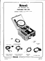
PORTABTE TEST SETS
MODELS P-850]-A & P-850] -A-24Y
DELUXE RECEIVER
RF INPUT CABLE
DELUXE BECEIVEN
DELIXE TRANSMITTER
ADAPTER CABLE
ADAPTER CABLE
Motorola
Printed in U. S.A.
s/52-cP
EXTENSION
CABLE
HF PROBE CABLE
Communications and Electronics Division
Blvd. . Chicago 51, [tinois
4545 Augusta
-i-
54P89 r 69
Issue - B
0
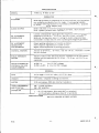
SPECIFICATIONS
MODEL
P-850r -A, P-8501 -L-24\
l-
OPERATION
ALIGNMENT
Metering facilities for alignment of receiver and tune-up of transmitter
are norrnally provided by use of a singl.e, ll-prong plug and cable.
Additional metering facilities are provided on 450-470 mc. equiprnent
by means of a special adapter plug.
AUDIO OUTPUT
Meter indication of receiver quieting is provided. 'Self-contained
P. M. speaker permits audio reproduction.
RF ALIGNMENT
GENERATOR
Crystal controlled RF signal generator allows accurate peaking and
alignment of.25-50 rnc,, 72-76 mc. and I52-L74 mc. receivers.
Motorola 4-prong oven-type or 2-prong bi-metal comPensated type
transmitter crystals may be used in peaking and alignment generator.
RF ALIGNMENT
GENERATOR
ADJUSTMENTS
Output peaking adjustment of crystal oscillator.
Fine frequency adjustrnent of crystal circuit.
Signal output adjustment of peaking generator,
CRYSTAL TESTING
Activity of 25-50 rnc. , 72-76 mc, and l5Z-174 mc. transmitter crystals
may be checked.
FIELD INTENSITY
METER
Relative values of the RF field intensity radiated from the transmitter
antenna rnay be measured for 25-50 rnc., 7Z-76 mc, and L52-174 rnc.
equipment.
XMTR FILAMENT OR
CONTROL VOLTAGE
MEASUREMENTS
6 or IZ VDC voltages
P-850I -A:
P-850r -A-24Y: 6, LZ or 24 VDC voltages
a__,
GENERAL
SIZE
6-3f4" high x rL-L5/L6't wide x IO-15/I6" deep.
WEIGHT
L3-I/Z lbs. complete including accessories.
METER
0-50 microarnps; 2000 ohm internal resistance
TUBE COMPLEMENT
AND FUNCTION
3S4 - crystal oscillator
3S4 - RF amplifier
POWER SUPPLY
I
I
-L/Z volt battery (Eveready #467 or equivalent)
l-I/2 volt battery (Burgess type 2F or equivalent)
6?
SPECIFICATIONS SUBJECT TO C}IANGE WITHOUT NOTICE.
|
8
/52
54P89r690-B
,_,
\l
CHECK
\i/
I
THESE
OUTSTANDING
FEATURES
DESIGN
ACCESSORIES
y' Here is a compact unit packaged in a lea_
therette bound carrying case. A complete
portable test meter kit for testing all MOTOROl,A FM Z-way mobile transmitters and re_
y' Complete set of tuning tools, adapters, cables
and RF pickup probe are included. as part of
the model.
ceivers anda conveni.ent RF signalgenerator
for 2.fign6ent of 25-50 rnc. , 7Z-76 mc. and
I52-174 mc. equipment.
Crystal controlled signal generator with
adjustable output from 0 to more than g00
'I
P-7208 and p-2208-A RF Dummy Loads to
work in conjunction with the test set for mea_
suring transmitter RF power outputare avail_
able at additional cost.
y' Completetestingfacilitiesfor 6VDC, lZ VDC
and I l7 VAC operated units. 24 VDC operated
'I
25-50tnc.,'lZ-76mc. and l52 -174rnc. trans_
mitter crystals for RF signal generator avail_
f
microvolts.
able at additional cost,
units may be tested (p_8501 _A_Z V).
y' Precision Zls metalized multiplier resistors
in meteringcircuits with 4'r2000 ohm meter.
y' Provides meter indication of relative lad.iated
antenna power for 25-50 rnc., 72_76 mc. and
mc, equipment.
y' Microphone jack to allow local transmitter
r'
A 455 kc. crystal unit for exact alignment of
the SENSICON receiver Final lF and dis_
criminator circuits is available at additional
cost. (tr,tOtOROf,a part No. 48880I065. )
r'
A 457 kc. crystal unit for exact alignment of
the UNI-CHANNEL receiver Final IF and
discriminator circuits is available at addi_
tional cost. (MOTOROLA part No. 48K803524)
152-174
control modulation,
f
e
Self-contained spring loaded switch for trans
mitter on-off control.
/52
_
-111-
54P89 169 0 -B
TABTE
OF
CONTENTS
NUMBER
SECTION
Page
I.
INTRODUCTION
Z.
DESCRIPTION
3.
CONTROLS
4,
FUNCTIONS
Page
Page
a. Metering
y""t":T:lt
;: nl".i''ui Relative Aud-roMeasurement
'
Relative Field Strength
Receiver
":
sENSrcoN
;: iso-+to Mc.
Y::t]*:"-l
voltage Measurement
Grid Current Measurement
rir"-""t
:: ;;;;";t'.;
;. iransmitter Plate
;
;.
;.
Voltage Measurement
Re."ilre" Quieting Measurement
Peaking Generator OPeration
n"..i"!t
j: P-iioe
Znd IF Stage Alignment
and P-7208-e er DummY Load
6.
LIST
SCHEMATIC DIACRAM PARTS
7.
CRYSTAL UNIT
)
z
3
3
4
4
4
Page
5
Page
Page
Page
7
5
7
Page
OPTIONAL ACCESSORIES
q
Page
Page
Page
Page
Page
Page
Page
Page
8
Page I I
Schernatic Diagram
P-8501-A and P-8501 -A-ZAV
$D89r692
J.
54P89 I 690 -B
-lv8
/5r
Motorola
PORTABLE TEST SETS
I
P-8501-A
I.
& P-8501-A-24V
INTRODUCTION
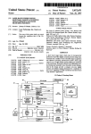
The MOTOROI,A P-8501-A and P-850I-A-24V
Portable Test Sets ate universal instruments for
testing MOTOROLA radio transmitters and receivers. By their compact, portable design they
lend themselves readily to fieldor bench applications. Specifically, these instrurnents are engineered for use with MOTOROLA "RESEARCH"
Line communication equipment. With the adapter
cables suppliedthey may be used to test and align
other lines of MOTOROLA equipment as well'
Complete testing and alignment may be accomplishld for all MOTOROLA 25-50 tnc', 72-76
mc. and l5Z-174 mc. frequency range equipment
with the aid of P-8501-A Series Test Sets' For
450-4?0 mc. "RESEARCH'r Line equipment, the
P-8501 -Ais applicable only for metering purPoses
and is not to be used as a signal soutce for alignment.
U
Alignment procedures as described in the
discussions to fo11ow, will apply primarily to
25-50 rnc., 7Z-76 ms. and l5Z-I74 mc' equipment. For alignment of 450-470 mc' equipment
refer to the comprehensive alignment procedure
as outlined in the associate insturction manual
for the equipment being tested.
2.
DESCRIPTION
The P-850I-A PortaLle Test Set is designed
primarily foruse with MOTOROLA equipmentoperating from 6 VDC, lZ vDC, and l17 VAC pri-
mary power sources. The P-850I -A-Z4V Portable
Test Set is especially suited for use in testing
MOTOR3LA equiprnent operating from 24 VDC
power sources. The P-8501-A-24V and P-8501-A
Test Sets differ only with respect to the value of
a multiplier resistor used in the DC transrnitter
filarnent-control voltage metering circuit' This
provision allows'ron-scale'r meter readings of Z4
VDC transmitter filament voltages with the
P-850I -A-Z4V Model. This model Test Set is
identical inall other functions tothe P-850I-A and
may be used for complete testing of MOTOROLA
equipment operating from any voltage sou!ce'
However, 6 VDC and l2 VDC measurements with
the P-8501 .?--Z V will not produce meter deflections of the magnitude attained with the P-8501-A
and therefore is not to be preferred for specific
6 vDc, lz vDc and Il? vAc MOTOROLA equipment applications.
The test set incorporates a 0-50 microampere
2000 ohm meter, whichwithtlee frontpanel selec-
and associated adapter plugs, provides
metering for all transmitter and receiver circuits
tor switch
.l
I /52
54P891690-B
included
essential to tuning and checking' Also
multiand
oscillator
in the test set is a crystal
transmitter
associated
an
of
aid
pif"t, With the
oscility"t"fandan applicable IF crystalthe test
a source
laior ot peaking generator maybe usedas z.'d t52'
;;-;;"; "'ig.'"t io-' zs-so tnc" 72-?6 mc
set may
test
The
alignment'
iZ+ -.. i"..i,'e"
meafor
meter
b" used as a field strength
in
strength
field
"t"o
surement of relative transmitter
which
functions
Other
ranges'
these frequency
relative
*"y U. performed *1th ttt" test set arerneasurequieting
.odio *L""urement, receiver
plate
rn".rt, ,t"rr"mitter filament measurement and
is used when
chief applilts
measuring very small currents'
Loads'
Durnmy
Series
cations are withthe P'7ZOB
MOTOROLA
line
older
and
and with DELUXE
(3)
0-50 ua.: this switch setting
equipment.
6-IZ CRYSTAL
e.
srnTEEjlti:I-
for
Used to provide Proper filament voltageused
be
to
are
which
6, lZ ot 24 volt crystals
with the Test Set oscillator'
METER SELE CTOR
f.
S*itj!:-xi""-!: titigl
voltage measurement' The P-8501-A and
and
P-850I -A-Z Y may be used with the P-?208
power
RF
measure
to
P-?208-A RF Durnmy Loads
The P-720& and P-7208-A are optional
"*p"t.
available at extra cost'
accessories
set
tesi
Provide s circuit selection when
of
specific equiPment' The particular function
equiPthe
uPon
dePend
will
each switch Position
ment being tested.
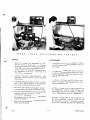
3.
g.
CONTROLS
the
The following controls are provided on
Their
Sets'
Test
P-8501-A and P--8501-}--Z41V
partigeneral functions are as designated' The these
with
cular circuits which can be measured
being te sted '
Te st Sets will depend on the equipment
of this
manual
instruction
Refet to the associated
speina
functions
meter
particular
equipmentfor
cific aPPlication.
GRID CURRENT -METER -F IELD STRENCTH
a.
Selector Switch
(I) GRID CURRENTposition: measures grid
current of internal test set oscillator'
(2) METER position: used for general
metering.
(3) FIELD STRENGTH: used primarilv to
radiation of a transmitter '
-.""o". relative signal
metering
ON-OFF Switch
Controls battery Power to Test Set peaking
generator.
h. ADJ. Control
Allows fine frequency adjustment of Test Set
crystal oscillator.
i.
OSC TUNE
Allows peaking of crystal oscillator plate cir cuit to provide maximum oscillator output'
Provides adjustment of peaking generator
output from 0 to more than 800 microvolts'
1.
FUNCTIONS
NOTE
The followi.rg t""t S"tfunctions which do
not bear asterisk suffixes are applicable
to MOTOROI,A equipment of aI1 frequency
ranges. Those functions designated -*-
Allows reversing of meter polarity
will apply only to 25-50 tnc" 72-76 rnc'
and l52-l?4 mc' equipment' Designations
-**- refer to 450-4i0 mc' equipment only'
XMTR ON Switch
c.
J_-
ATTENUATOR Control
J.
METER PoLARITT-E-1!9h
b.
Control
Provides a Test Set controlforkeyinga transmitter being tested
a.
Mete
ring
(l) DISPATCHER and "RESEARCH" Line
d.
EquiPment
(1) REC position: used primarily for re-
(") PlacetheREC' -XMTR'-0-50 switch
upon
in the REC. or XMTR' position' depending mebeing
is
receiver
or
whether a transmitter
ceiver metering
(Z) XMTR position: used primarily for
tered.
t,ransmitter metering
J
8/52
-2-
54P891690-B
b.
(b) Place the GRID CURRENT-METER-
Receiver Relative Audio Measurement
FIELD STRENCTH switch inthe METER position.
(l) DISPATCHER and "RESEARCH" Line
(.) Insert the 1l pin metering plug into
the METER receptacle on the chassis being me-
Receiver
te r ed.
(") Place the REC. -XMTR.-0-50 switch
ttre
in
REC. position.
(d) Refer to the MOTOROLA lnstruction
to the unit undergoing test for
applicable
Manual
prope r te st set switch settings and mete r readings.
(b) Place the GRID CURRENT-METERFIELD STRENGTH switchinthe METER position.
(z) DELUXE and other MOTOROLA Equip-
(.) Insert tire if pin metering plug into
the METER receptacle on the receiver chassis.
ment
(") Placethe REC.-XMTR.-0-50 switch
in the 0-50 position.
(d) Place the 9 position meter selector
switch in position 8.
(b) Place the GRID CURRENT -METERFIELD STRENGTH meter intheMETER position.
(2) DELUXE and other MOTOROLA Receiver
(.) Place the 9 position meter selector
switch inthe *4 or -4 position depending upon the
direction of the needle deflection. Positions *4
and -4 act as a meter polarity reversing switch
in this application.
(") Place the REC. -XMTR. -0-50 switch
in the REC. position.
(b) Place the GRID CURRENT-METERFIELD STRENGTH switchinthe METER position.
(.) Connect the l1 pin metering plug to
the RED adapter having the two pin connectors.
meternor.tffiy
alsobe reversed
by the - * switch directly beneath the
meter. The reversing switch is primarily used to reve rse the meter polarity
when measuring the battery voltage of a
mobile unit in position 8 of the metering
switch.
The
s
(d) Plug the two pin connectors into the
on the receiver chassis.
receptacles
speaker
(") Place the 9 position meter selector
switch in position 8.
(d) Insert the Il pin metering plug into
the proper adapter recePtacle.
c. Relative Field Strength Measurement -*-
When metering a transmitter use the BLACK adapter. Plug the adapter meter
(I) Connect the RF probe extension cable to
the PROBE connector on the test set.
l.
connector into the transmitter METER jack.
(Z) Connectthe RF probe cable withthe suction cup to the extension cable. The suction cup
may be usedto secure the RF probe toa car body
or other fixed object.
Z, When meteringa receiver - use
the RED adapter. Plug the adapter metet connector intothe receiver METER jack and plug the
two pins into the receiver SPKR receptacles.
(3) Place the GRID CURRENT - METERFIELD STRENGTH switch in FIELD STRENGTH
position.
CAUTION
DO NOT usethe RED adaPter to meter a
transmitter. The transmitter B* will be
connectedto one ofthe speaker pins when
measuring PA Plate current.
(4) Place the REC. -XMTR. -0-50 switch in
the XMTR. position.
(5) Key the transmitter by pressing the
XMTR-ON momentary switch. The transmitter
may also be keyed by a rnicrophone connected to
the test set.
(") Refer to the MOTOROLA lnstruction
Manual applicable to the unit undergoing test for
proper meter readings of the various stages.
I /52
-3-
54P891690-B
equiPment, a seParate voltage "o:
supplies power to the transmitter fila*".rt ".ra the control circuits' In these
instances the following test procedure
allows control voltage measurement only '
NOTE
set'
To key the tranimitter with the test
the Ii pin meter plug mustbe connected
to the METER receptacle on the transmitter chassis'
(6) lf the meter should read off scale; reduce
or bv
the sig.rat strength by folding the RF probe antransmitting
the
from
away
it
further
.rrovi.r*g
t.rrrr".- This procedure will permit a transmitter
to be adjusteJ for maxitnum radiated signal'
d.
450-470
ffiott.n@
To accurately align a 450-470 mc' SENSICON
multireceiver, the measurement of lst and Znd can be
Provision
essential'
is
ptiet gtia current
of a
made for such measurernent by application
an
oPas
available
is
K-93? 6 adapter plug which
tional accessory'
in
To measure the multi'plier grid current
follows:
as
proceed
450-470 mc. receivers
(
I
) Plug the K-9326 adapter
into the METER
receptacle on the receiver'
(Z\ Connect the 1l pin meter plug to
the
adapter.
(3)
Place the GRID CURRENT - METER-
position'
FIELD STRENGTH switch in the METER
(4) Place the REC' -XMTR' -0-50 switch in
the REC. Position'
(5)'-+Place the 9 positionmete-r selector switch
position for Ist multiplier grid current
in ttre
measurement.
Place the switch in the 5 position for Znd
multiplier grid current measurement'
(6) Read the grid current on the Test
Set
meter.
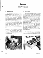
e. Transmitter Filament-Control Voltage Measurement
NOTE
from a
For most equipment operating filament
DC power source' transmitter
voltages and control voltages are derived
from the same A- supply' In these inalstances the following test procedure
both'
of
measurernent
lows simultaneous
sorne cases' Particularily with AC
ln
DISTo measure "RESEARCH" Line and
:
voltage
PATCHER transmitter filament-control
(l) lnsert the 1l pin meter plug into the
chassis'
METEh. receptacle on the transmitter
(2) Place the GRID CURRENT - METERposition'
FIELD STRENGTH switch inthe METER
(3) Place the REC' -XMTR' -0-50 switch in
the XMTR. Position'
in
(4) Placethe - * switch beneaththe meter
mothe
o{
the (+) position if the positive terminal
it in the
bile unit's battery is grounded or place
battery
the
of
terminal
(-)position if the negative
is grounded'
(5)
switch
Place the 9 position meter selector
in position 8'
(6) The meter rpill read filament-control
voltage when the transmitter is in the "standby"
condition as follows:
the P-8501-A Test Set multiply
0' 3 to obthe meter reading in microamperes by
tain the filament voltage in volts'
(.)
On
L
the P-8501-A-24V Test Set the
directly 0-50 volts'
reads
meter reading
(b)
On
Transmitter Plate Voltage Measurement
To measure "RESEARCHTT Line and DIS:
PATCHER transmitter plate voltage
f
.
(l) Insert the I I pin meter plug into the
MET;R receptacle on the transmitter chassis'
(Z) Place the GRID CURRENT - METERposition'
STRENGTH switchinthe METER
FIELD
(3) Place the REC' -XMTR' -0-50 switch in
the XMTR. Position'
switch
(4) Place the 9 position meter selector
the
when
zero
read
will
i., po"itio.t Z. The meter
Multicondition'
the'rstandby"
transmitter is in
obtained
ply the meter reading in microamperes of Z0 to
factor
a
by
in the 'ttransmitrr toiditiott
determine the plate voltage in volts'
I4
54P89I690-B
8
/52
CAUTION
DO NOT use K-9326 adaPter Plug when
metering a450-470 mc. transmitter. Use
of this adapter rnay result in serious
damage to the test set meter.
t
Receiver Quieting Measurernent
c.
DISPATCHER and "RESEARCH" Line Receive r s
Quieting signal isthat input signal necessary
to reduce the output noise' at the speaker, Z0 db'
This measurement is to be made in a well shielded
location in the absence of extraneous noises'
This measurement is important, in that it
indicates in one measurement that the signal-tonoise ratio ofthe receiver RF stage is satisfactory
and that there is sufficient gain, i. e. that amplifier tubes are working norrnallY.
The actual measurement is made by observ-
ing the noise voltage at the speaker without any
carrier atthe antenna. Then sufficient carrier is
introduced atthe antenna to reduce the noise output voltage lo If L0 its former value.
To measure the quieting signal accurately on
25-50 mc. , 7Z-76 mc. and l5Z-174 mc. receivers
a Model 80 Signal Generator or equivalent and a
MOTOROLA P-850I-A Portable Test Set are required.
To measure the quieting signal on 450-470
mc. receivers, a ModelM360 MeasurementCorp'
Signal Generator or an equivalent and a MOTOROLA P-850I-A Portable Test Set are required'
The proper procedure is as follows:
(I) Turnthe signal generator 'ronrr and al1orl
the signal to stabilize by a rrwatrn-up" period of
I-lfz ro 2 hours.
il
\,
6 db. pad. The exact carrier frequency will be
indicated by a zeto reading on the test set meter
withthe 9 position meter selector switch in position 4. (The AFC switch should be placed in the
rrOFFt' position on receivers employing this con-
trol.
(6) Place the 9 position meter selector switch
in position 8.
(?) Turnthe receiver SQUELCH control fully
counterclockwise (OI. F)'
(8) Withno signal inputto the receiver (sigattenuator control setfor zero outgenerator
nal
put), adjust the VOLUME control for a reading of
8. 0 on the test set rneter.
(9) Adjust the output level of the signal generator until the receiver audio is decreased to a
reading of 0. 8 on the test set meter.
(10) Note the setting of the signal generator
output control. This value (microvolts) is the 20
db. quieting sensitivity of the receiver'
(Il)
h.
Peaking Generator OPeration
-*-
The peaking generator provides a crystal
controlled source of RF signal for aligning most
MOTOROLA receivers. The peaking generatbr is
designed to use the transmitter crystal for operation in the 25-50, 7Z-76 and 152-174 megacycle
bands. The stages are broadly tuned and therefore the output will be at all harmonics of the
crystal frequency.
) Place the transmitter crystal for the as sociated carrier frequency or its equivalent into
the appropriate crystal socket on the test set'
(
I
IMPORT4NT
When aligning-;=;;eiver in the 25-50
rnc. range with an FMT-5 transmitter
crystal, place the #IX89I07Z adapter in
the crystal socket onthe testmeter' This
adapter isan optionalaccessory not normally suppliedwiththe test set' The item
however will be furnished by MOTOROLA
at no extra cost per customer request'
Place the FMT-5 crystal in the adapter'
The adapter places a capacitor in series
which permiti; the oscillator to be tuned
to the correct frequencY.
chassis.
(3) Place the REC' -XMTR' -0-50 switch in
position.
REC.
the
(4) Place the GRID CURRENT - METER-
FIELD STRENGTH switchinthe METER position'
(5) Connect the signal generator' adjusted
to the desired carrier frequency, to the receiver
antenna input connector using a coaxial lead and
/52
Disconnectthe Test Set and Signal Gen-
erator.
(Z) Connect the lI pin meter plug from the
test set to the METER receptacle on the receiver
8
)
-5-
54P891690-B
The Test Sets contain a6-I2 switchwhich
resistor in series withthe crysdropping
a
places
ial heater when in position 12' The use of this
switch on the test set depends upon the Power
source ofthe receiver being aligned and the voltage rating of the crystal heater' The proper seting for this switch is indicated below'
(7) Place the GRID CURRENT -METERFIELD STRENGTH switchinthe GRID CURRENT
position and set the ATTENUATOR in the maxiLom output position. Check the meter for test
set osciliator grid current - - with crystals of
normal activity the meter will read above I0
(") Position 6, when aligning a 5 VDC
or 117 VAC receiverusing a crystal with a 6 volt
heate r.
(8) Return the meter switch to the METER
position and place the selector switch in position
t. Tune the output of the peaking generator for a
maximum meter reading by'adjusting the control
(b) Position I2, when aligninga 12 VDC
receiver using a crystal with a 6 volt heater'
(.) Position 6, when aligning a l2 VDC
receiver using a crystal with a I2 volt heater'
(d) Position 5, when aligning a 24 lDC
receiver using a crystal with a 24 volt heater'
NOTE
When aligning a 24 VDC receiver the
transmitter crY stal must have a 24 volt'
heater.
(Z) Transrnit a carrier signal of the frequency of the receiver being tested from an associated transmitter. lt is recommended that the
test transmitter be located sufficient distance
fromthe receiver so that the received signal will
be relatively weak.
(3) Adjust the discriminator coil for zero
meter indication for all receivers within the spe-
cified frequency ranges except the SENSICON and
UNI-CFIANNEL receivers' When aligning these
receivers, ad,just the first local oscillator coil
for zero discriminator indication'
rnicroamPere s.
marked OSC TUNE as follows:
(") Set the ATTENUATOR control to
maximum. Tune the OSC TUNE control for a
maximum meter reading. BE SURE THE OSCILLATORIS ONA TRUE PEAK. ltispossible under
certain circumstances to have the crystal lose
control of the oscillator. Self-oscillation of the
peaking generator can be readily detected by
switching the test meter to position 4' Rapid
fluctuations of the meter as a hand is placed on
the crystal indicates self-oscillation' The OSC
TUNE control should be carefully adjusted until
RF output is obtained which provides a stable
meter reading. Screw the slug all the way out'
The large p."t" that are wrong will be unstable'
(b) After obtaining a maximum reading'
reduce the ATTENUATOR level and repeak the
meter with OSC TUNE control' Repeat this procedure a few times, but do not set the ATTENUATOR level so low that the oscillations stop as
indicated by a zero meter reading when the GRID
CURRENT-METER-FIELD STRENGTH switch is
placed in the CRID CURRENT position'
position 4 '
) Place the selector switch in
zero disfor
crystalfrequency
set
Adjust thetest
capacontrol
the
with
reading
meter
cirminator
citor marked ADJ on the test set'
(9
(4) Connect the output of the peaking generator, RF OUT, to the ANT connector of the antenna relay on the transmitter chassis using the
cable supplied with the test set' A ground connection mustbe made between the test set and the
receiver being aligned to permit operation of the
test sets crystal heater. The shield of the RF
cable is used for this PurPose'
(10) Place the sele ctor switch in po sition I
or 2 (position 2 is more sensitive but saturates
for lower signal levels). Keep the oscillator out-
put as low as Possible.
CAUTION
(5) Turn tronrrthe peaking generator with the
ON-OFF switch on the test set'
Care should be taken when reducing the
output of the peaking generator as the
ATTENUATOR is notlinear; however' it
will provide good control at low output
Ievels and will attenuate to zero output'
(5) Insert the 1l pin meter connector into
the DISPATCHERoT "RESEARCH" Line receiver
METER receptacle or use the adapter for DELUXE
and other MOTOROLA receivers having no I I pin
meter receptacle. Allow a short 'twarm-uPtt Period sufficient for crystal heating'
8/sz
l.
Align the receiver as outlined in the applicable MOTOROf.A Instruction Manual'
(ll)
-6-
54P89 r 690 -B
t
1.
The P-7208 RF Dummy Load is a radio freresistive load unit which is used in conjunction with the P-8501-A Test Set to measure
transrnitter RF power output. The unit has a
standing wave ratio of less than I.2 over a frequency range of 25 mc. to L74 mc. and has a nominal load impedance of 50 ohms. The RF power
capability of the dummy loadis Z5 watts for continuous operation and 60 watts for intermittent
SENSICON and UNI-CHANNEL Receiver Znd
quency
IF-t"g. Altg"-."t
The P-8501-A may be used to align the final
IF of SENSICONand UNI-CIIANNEL Receivers in
all frequency ranges if an additional 455 kc. or
45? kc. i.s purchased for use with the peaking
generator.
If a SENSICON receiveristobe aligned a 455
kc. crystal should be used - MOTOROLA Part
No. 488801055. If a UNl-CHANNEL receiver is
to be aligned a 457 kc. crystal should be used MOTOROLA Part No. 48K803674. These crystals
should be ordered from MOTOROLA lNC., I3Z7
West Washington Boulevard, Chicago 7, Illinois.
ope
ration.
The P-7208-A RF Dummy Load. is the same
as,the P-7208 except that the maximum power
rating is 2 watts. The P-7208-4 is designed for
use with the MOTOROLA Portable equipments.
To rneasure transmitter RF power output:
The following procedure shouldbe used when
aligning the Znd IF of SENSICON and UNI-CIIAN-
NEL receivers.
(l) Place the GRID CURRENT-METERFIELD STRENGTH switchinthe METER position.
(I) Plug the 455 kc. or 457 kc. crystal into
the two pin crystal socket on the test set,
(z) Place the REC. -XMTR. -0-50 switch in
the 0-50 position.
(2) P1ACC thg GRID CURRENT - METERFIELD STRENGTH meter in the GRID CURRENT
(3) Place the 9 position meter switch to the
*4 position.
po
siti on.
ON
(4) Insert the 1l pin metering plug into the
BLACK transmitter adapter receptacle.
(4) Setthe ATTENUATOR control for rnaxi-
(5) Plug the adapter connector into the jack
the
on
RF Dummy Load.
(3) Place the ON-OFF switch in the
po
sition.
mum output.
(5) Adjust the frequency ADJ control for
maximum meter reading.
(6) Connect the RF probe cable to the
(6) Connectthe transmitter ANT. connector
to the coaxial connector on the RF Dummy Load
using the extension cable supplied with the test set.
a
RF
OUT receptacle. The extensioncable may be used
(7) Turnon thetransmitter power switch and
allow a one minute warm-up period.
(7) Lay the RF probe under the recerver
chassis near the Znd IF-I tube,
(8) Key the transmitter with the press-totalk switch on the microphone (in AC models a
test microphone may be connected on the power
(8) Align the receiver as outlined in the applicable SENSICON or UNI-CHANNEL receiver
section of your MOTOROLA Instruction Manual.
supply chassis).
if desired.
J.
P-7208 and P-7208-A Dummy Loads
(9) Note the reading on the test set meter.
Refer to the applicable calibration curve shipped
withthe RF Dummy Load to convert the indicated
microamperes to output watts.
-*-
NOTE
NOTE
The P-7208 and P-7208-A RF DummY
loads are optional items not supplied with
this Test Set. They must be ordered
separately if desired.
I /52
If the meter reads off scale, reverse the
meter polarity withthe - * switchbeneath
the meter.
-7-
54P89I690-B
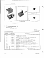
OPTIONAL ACCESSORIES
5.
%
K.9326
ADAPTEF KIT
s
COVER
FMT-5 CFYSTAL A|APT=
WITH CONNECTIONS
REMOVED
P-7208 SERIES
DUlviMY LOADS
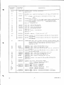
SCHEMATIC DIAGRAM PARTS LIST
6.
DELUXE TEST SET
Model: P-850I -A, P-850I -A-Z4V
Reference:
Schematic Diagram
63D89 I 692 -E
REFERENCE
SYMBOL
48X48 04 I 5
48lK24983
CI
zIK87I33
BATTERY, dry: 'rA"; l-I/Z volt
BATTERY, dry: "8"; 67 -lf Z volt
crz
zlR87 r27
2t883959
CAPACITOR,fixed:ceramic;tubular;1500mmfGMV;5C0vdcw
CAPACITOR, variable: air; 3-35 mmf; ADJ'
Same as C I
CAPACITOR, fixed: ceramic; tubular; 50 mnr{ +5{6; 500 vdcw
CAPACITOR,fixed:ceramic;tubular;500mmfmin';500vdcw
CAPACITOR, fixed: mica; 5600 mr,f +Z0o/o; 500 vdcw
CAPACITOR, fixed: ceramic; tubular; 4 mrof +' 5 mmf
CAPACITOR, fixed: ceramic; tubular; 4 mmf + 5 mmf ; 500 vdcw
I
CAPACITOR, fixed: ceramic; tubular; 24 mmf +5%; 500 vdcw; p/o L
CAPACITOR, fixed: ceramic; tubular; 100 mmf +20{'q; 500 vdcw
Same as C I
Same as C 5
p/o L 4
CAPACITOR, fixed: ceramic; tubular; 36 mmf +510t 5OO vdcw;
p/o L
500
vdcw;
mmf;
+'Z
I
mm{
tubular;
molded;
CAPACITOR, fixed:
c
c
2rK80ll39
CAPACITOR, fixed: ceramic; disc; ' 0I mf +80-20%; 450 vdcw
CZ
r9K29854
C3
C4
C5
zrP.47 457 3
C8
C9
c l0
c ri
C13
C14
/52
DESCRIPTION
PART NO.
BT}
BT2
C6
C7
8
MOTOROLA
15
16
zlB87 134
z 1R6605
2rK474609
or
21K47 4952
IR3 I493
2rK474009
Z
Same as C
5
Same as C
15
-8-
54P89 I690-B
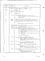
REFERENCE
SYMBOL
\y,
MOTOROLA
DESCRIPTION
PART NO.
CRYSTAL UNIT, rectifying: germanium
CRl
cR2
48A'90173
EI
31A892459
HOLDER, {use: single fuse mounting; for t -7f 4" Iong x If4" diameter fuse
FI
65A42869
FUSE, cartridge: one time; glass; l/200 ampere; 250 volt; Itrlong x
i/4" diameter
9A85615
CONNECTOR, receptacle; female; single contact; round; mica {illed bakelite
insulator; square mounting base; FIELD STRENGTH PROBE
CONNECTOR, receptacle; female; 4 contact; round; phenolic insulator;
JZ
Same as CR I
98 16345
MICROPHONE
Same as
L1
L2
L4
L5
L6
L7
248823247
24A77 336
24A47 0505
24847 5533
J I except RF OUT
COIL, RF: OSCILLATOR PLATE
C OIL, RF: choke; 4. 3 millihenrie s
COIL, RF: choke; 285 microhenries
COIL, RF: MULTIPLIER PLATE
Same as
L
Z
Same as
L
6
COIL, RF: choke; 3. I microhenries
24A8554r
LSI
508478023
SPEAKER, magnetic: 3. Z ohm voice coil; 3-lfZ'r
M
528474497
METER, ammeter:
0
to 50 microampere; 2000 ohm DC; 4" black bakelite
case; METER
or 528
88 028
r.
METER, ammeter: 0.to 50 microampere; 2000 ohm; DC; 4" black bakelite
case; METER
P]
28B8r357
6
U
CONNECTOR, plug: male; Il contact; polarized; round; black phenolic base;
does not include \V483723 Connector Shield and Handle Assembly or
4IA483715 Connector Shield Spring; which must be ordered
separately; pfo W I
RI
R2
R3
6R6326
6R63
7 3
17K892454
P-8501-A
or 17K8r !97 4
R4
R5
R6
R7
R8
R9
R IO
S1
S2
r7K892453
r7K892455
r 7K86037
6R6048
r
8A8 08 65
408892458
408892457
S2A
S2B
s3
40A47 5597
or 40K8 11760
S4
408892456
S44'
S4B
S5
RESISTOR, fixed: carbon; I00 ohm +10%; I/Z w; ins.
RESISTOR, fixed: carbon; 150 ohm +l0o/o; Lf Z w; ins.
RESISTOR, fixed: carbon film; 280,000 olnrn +Lls; IfZ w; ins.; used only on
40A482097
or 40A8 11825
RESISTOR, {ixed: carbon film; 980,000 ohm lfZ w; ins. ; tZlo; lns'; used
only on P-850I -A-Z4V
RESISTOR, fixed: carbon film; I?,500 dnm +2%; lfZ w; ins.
RESISTOR, fixed: carbon {ilm; Z0 megohm +2%: 2 w; ins.
RESISTOR, fixed: wire wound; 7 ohm +5%; l0 w; ins.
RESISTOR, fixed: carbon; 47,000 ohm +I0%; l/2 w; ins.
Same as R 2
RESISTOR, variable: wire wound; 50, 000 shm +Z1slo; ATTENUATOR
Same as R 7
SWITCH, lever action: three position; two PoIe
SWITCH, rotary: Z section; 9 position; consisting of :
I section, 9 position; front section
I section, 9 position; rear section
SWITCH, toggle: D, P. S. T. ; XMTR ON
SWITCH, toggle: D.P. S. T.; XMTR ON
SWITCH, .rotary: 2 section; 3 position; consisting of:
I section, 3 position; front section
I section, 3 position; rear section
SWITCH, toggle: S. P. S. T. ; 6 volt and 24 volt closed - IZ volt open
SWITCH, toggle: S. P. S, T, ; 6 volt atd 24 volt closed - l2 volt open
t,
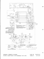
8/52
-9-
54P891690-B
REFERENCE
SYMBOL
MOTOROLA
DESCRIPTION
PART NO.
40A47 4034
S6
or 40K8rr752
s64
S68
40A80246
S7
or
0K8 r l75l
4
VI
v2
354
wl
rY 47 5527
SWITCH
SWITCH
toggle:
toggle:
D P S. T
D P S. T
ON-OFF; consisting of
p/os6
p/obo
SWITCH
SWITCH
toggle: D P D T
toggle: D P t) T
TUBE, electron
Same as
VI
CABLE ASSEMBLY, special' Purpose: METERINC; includes:
30A474498 CABLE, special purpose; lI conductor; rubber covered;
3-I/Z 1r. long required
ReferencePartPl
X1
xz
x3
9K828 I 0
9A3045 I
9K87 lZ4
.'
SOCKET,crystal:female;2contact;rectangular;blackbakelitebase
SOCKET,crystal:female;4contact;square;micafiliedbakelitebase
socKET,tube:female;Tcontact;miniature;round;micalilieciphenolic
base; includes center shield; saddle mounting
Same as
x4
'V/
ON.OFF
X
3
MISCELLANEOUS NON-REFERENCED PARTS
3
3
6X8 09 I2
0A7 68 58
26A890034
rv892448
KNOB: bar; for reference Part R 9
CABLE, special Purpose: Z conductor; rubber covered: one l2" long ani
one
I7" long lengths required
SHIELD, tube: {or reference part V l, Y 2; Z required
CABLE ASSEMBLY, special purPose; BATTERY: includes:
3lKBgz4ZZ CONNECTOR: I single male and 1 single fena'e contact;
snap type; mounted on a rectangular phenolic s:r:p
Z8K!ZZ49 CONNECTOR, plug: male; Z contact; pin t-vpe: :ound
bakeiite insulator
],0M50 WIRE, electrical: #?4 ga
long required
10M52 WIRE, electrical: ft24 ga stranded.; codeC, RED: I4-l/2"
long required
v
ACCESSORY PARTS (SUPPLIED)
IV475530
LINE, RF transmission: RF PROBE; assembly; includes:
62" 30K475278 CABLE, RF: coaxial; RC-58A U
I 9A85615 CONNECTOR, plug: female; single contact
I5A483599 SHELL, connector: {or 9A856I5 CONNECTOR plug
I
37A475539 CUP, suction
|
IV47553 I
LINE, RF transmission: assembly; EXTENSION; includes:
4Z't 30K475378 CABLE, RF: coaxial; RG-58A1I-l
Z 28A85558 CONNECTOR, plug: maJe; single contact
rv 47 5525
LINE, RF transmission: assembly; DELUXE RECEMR RF INPUT:
include s:
39" 30K475378 CABLE,
I
I
r.
v892 541
RF: coaxial; RG-58A/U
28A85558 CONNECTOR, plug: male; single contact; UHF type
28A808i 0 CONNECTOR, plug: male; single contact
CABLE ASSEMBLY, special purpose: DELUXE RECEMR ADAPTER:
include s:
l04" 30A76858 CABLE, 2 conductor: rubber covered
I 28A19484 PLUG, telephone: 2 contact
|
9K892736 CONNECTOR, plug: female; ll contact
U
I /52
54P891690-B
REFERENCE
SYMBOL
MOTOROLA
PART NO.
DESCRIPTION
v
1 I5K893642 SHELL, connector: for 9K892736 CONNECTOR,pIUg
I 29K5405 CONNECTOR, plug: male; single contact; pin type;
|
coded; black
29K5407 CONNECTOR, plug: male; single cbntact; pin type;
coded; white
rv89364r
CABLE ASSEMBLY, special purpose: DELUXE TRANSMITTER ADAPTER;
include s:
36" 30A76858 CABLE, special purpose; 2 conductor; rubber
I
I
I
covered
28A19484 PLUG, telephone: Z contact
9K892736 CONNECTOR, plug: female; I1 contact
I5A483149 SHELL, connector: Ior 9K892736 CONNECTOR,
Plug
66A891568
66A474489
66A'48
r 9 53
TOOL, alignment: double ended screwdriver; 6" long
TOOL, alignment: double ended; slotted plug; recessed blade; 5-lfZ" Iong
TOOL, alignment: double ended; recessed blade; projected blade;
7
66K47 505r
7.
-5f16" Ioag
TOOL, tube puller
CRYSTAL UNIT
NOTE
CRYSTAL UNITS are not part of the P-8501-A or P-850i -A-Z4V
TEST SET and must be ordered as a separate item.
YI
v
orY2
48B80i065 I CRYSTAL UNIT, quartz: IF A ignment; 455 kc.; MOTOROLA Type TX 1
or 48K803674 | CRYSTAL UNIT, quartz: IF A ignment; 457 kc.; MOTOROLA Type TX Z
or
Applicable Transmitter Crysta
Applicable Transmitter Crystal
Y-,
I /52
-Il-
s4P891690-B
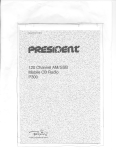
FIELD
STRENGTH
PROB€
J-1
Y
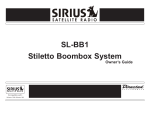
DA6RAM ]S APPLICABL€ AS ORAVI 1A 1A'
PROOUCTION VERSION INDICATED BY SUFF X
TBS
LAIESI
NUM8Effi IN THE IAgLE. IT IS APPLCABLE TO EACH
EAR!!ER PFOOUCTION VESION WHEN AMENOEO 3Y ,ZT
SERVICE EULLETINS LISTEO FOR SUCCEEOING VEreIONS
PARi NO rV893641
/
SocKET
TQ SPEA(ER IERMINALS
AOAPTER IO CHECK IST A
HC
CUFRENT OI 45O''?O
IO METEF
SENSICOX R€CEIVER
P-8501-A AND P-8501-A-24V
NO. 63D891692
ISSUE-E 8/ 52-CP
PAnT
MOTOROLA SCHEMATIC DIAGRAM
PORTABLE TEST SETS
JACK
Motoroli
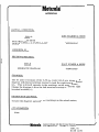
ADDENDUM
II{ANUAL AFF.ECTED:
PART I{UIItsER & ISSUE
IILL9:
POR.TABLE TEST SETS
MODELS P-85C1-A & P-8501-A-Z4V
54P89t690-C
ADDENDUM #I
SECTION AFI"ECTED:
o.
e
IIa!s
SCHEMATIC DIAGRAM
PAR.T NUMBER & ISSUE
63D89 t69Z-E
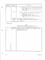
CHANGES.:
the {+} and (-) terminals of the 0-50 ua. meter (M-l} are shown on the
diagram with the left terminal marked (-) and the right terrriinal marked
(+). This is directly opposite to the markings on the aetual metero
Change the diagram to show the left terminal. marlced (+) ana the right
terminal marked (-)o
REASON FOR CI{ANGES:
To have the diagram agree with the markings on the actual metero
aTrecH.YElvTsr
None
tlotoroh
ffEit'?;3*"fr i"::u'iii::;:';i,T'iiiHt
A.DD"
#l
DATE IZI53
IUOTOROLA
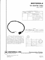
TEST ADAPTER CABLE
MODEL TKN60254
ARTS LIST lqt Schematic Diagram 638862694-A
REFERENCE
SYM BOL
MOTOROLA
PART
P1
9C86864
PZ
I V8
DESCRIPT ION
NO.
CONNECTOR, plu
femalc: I I contact; does notincl
15A483149 SHIELD, piug
0
assr.: c lor 288864669 PLUG,
male; lZ contacts 15A864670
75.1A2 6
SHELL, pLug 37K103664 GROMMET 42,4'82740 CLAIv{P, cabte;
2 reqrd 357287 SCREW,
machine (4-36-318)
REVIS IONS
D
IAG,
CHASSI S
ISSUE
SUFFIX
1
AND
NO.
KN6025A
RE F.
SYMBOL
P:
CHANG E
LO CAT ION
\\ _\s 28B8a,466r CON
NtrCTOR,
PARTS LIST
PLLTG
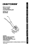
When using a Motorola Partable test set to
rneter a rrMotracr'@, rrBusiness Dispatcherr,, or
trMocorn . Jgrr@Mobile FM Two-Way Radio, or
Aleri Monitor receiver the Model TKN6025A
Adapter CaUie must be used. The adapter cable
has an 11-pin fernale receptacle on one end and
a 12-pin rnale plug on the other end. Connect the
Il-pin receptacle to the test set rnetering cable
and the 12-pin plug to the rnetering socket of the
transrnitter or receiver of the radio set.
TWOTOFSOLA INC.
ENGINEERING PUBLICATIONS
Copyright 1967 by Motorola, Inc.
Printed in U. S.A.
tz l5 /67 -uP
(C
orxl
4501 WEST AUGUSTA BOULEVARD
rt:r tt
n icatiotts
Elivision
cHlcAco, rl-LrNors 60651
68P862697
Issue - D