1
1.0 General Section
1.0 General Section
Table of Contents
1.1
Purpose
1.2
Introduction to the Telephone Package (Motorola digital Phone)
1.2.1 CDMA, TDMA and GSM Protocols
1.2.2 CDMA, TDMA and GSM Handset Descriptions
1.2.3 Phone Activation/Programming
1.3
Telephone System Components
1.3.1 Phone Cradle
1.3.2 Microphone
1.3.3A Portable Support Electronics Module (PSE)
1.3.3B Communication Platform Module (CP)
1.3.3C Multiple Handset Interface Module (MHI)
1.3.4 Handset
1.3.5 Compensator
Mercedes Benz Technical Manual for Telephone v4.6
Date: 09/01/2004
1.0 General Section
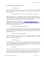
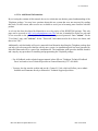
1.1
Purpose
This manual was written to familiarize the Mercedes-Benz Service Technician with the telephone
system designed by Motorola for Mercedes-Benz MY00 thru MY05 vehicles. It is recommended that
this training manual be reviewed prior to performing the installation of the telephone package. This
document is not an installation guide or procedure, a separate Mercedes-Benz manual has been created
for that purpose. However, basic troubleshooting charts are included as a part of this document to assist
in correcting problems that may occur.
1.2 Introduction to the Telephone Package (Motorola Digital Phone)
Prior telephone systems that have been installed in Mercedes-Benz vehicles have used only 800MHz
analog technology. The MY00 uses the 800MHz analog/digital and MY01/05 uses 1900MHz digital in
addition to 800MHz analog/digital. MY00 thru MY04 telephone packages use CDMA or TDMA
protocols and, MY05 vehicles offer the option of GSM as a third protocol depending on the model
selected for installation, which will be determined by the customer and/or carrier availability.
Additionally, the telephone package has the ability to automatically default to an analog signal if a
digital signal is not available, or is too weak to provide a quality conversation.
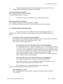
The telephone package allows calls to be made and received without taking your eyes off the road or
your hands off the steering wheel. This is accomplished by integrating the phone with the
multifunction controls located on the sides of the steering wheel (if equipped) and through Voice
Recognition (if equipped). Displays on the MCS, Audio 30 or COMAND relay information, such as,
numbers stored in the handset’s memory, signal strength, etc. Refer to the K2OPTION owner’s manual
for details on the various features of this system.
1.2.1 CDMA, TDMA and GSM Protocols
CDMA is an acronym for Code Division Multiple Access. It is one of several methods of providing
digital cellular service. CDMA imposes several digital signal patterns, one pattern per conversation,
on a single carrier frequency. The communication link (conversation) is kept separated from other
links by the ability of the telephone to only recognize its assigned signaling pattern (code). CDMA
technology is popular because it provides for a large number of communication links on a single
carrier frequency, but one of its drawbacks is that as more links are established, distortion and
interference increases.
TDMA stands for Time Division Multiple Access, and is another method of providing digital cellular
service with multiple links (conversations) on the same carrier frequency. It differs from CDMA in that it
uses slots of time for each link. Each time slot repeats continuously at a predetermined rate or speed.
Samples of each link are taken at the same rate and mixed with the carrier frequency, each in its turn. On
the receiving end, the receiver selects the data from the time slots of the assigned communication link,
Mercedes Benz Technical Manual for Telephone v4.6
Date: 09/01/2004
1.0 General Section
and then filters the data to provide a good representation of the original information.
GSM stands for Global System for Mobile Communication, and is similar to both CDMA and TDMA
protocols in that it also provides digital cellular service with multiple links (conversations) on the same
carrier frequency. Like both CDMA and TDMA, GSM uses its own unique method of transmitting
conversation wirelessly. GSM is based on the platform of TDMA, but a more robust method when
utilizing the timeslots allotted for the milliseconds of data needing to be transferred/received. GSM is
also unique in that it utilizes a ‘smart card’ called Subscriber Identity Module (SIM) allowing for easy
portability between different GSM handsets. GSM handsets are not identified like both CDMA and
TDMA handsets by using an Electronic Serial Number (ESN); instead it is uniquely identified by the
International Mobile Equipment Identity (IMEI).
The type of digital handset that will be installed into the vehicle will be contingent upon the local
carrier’s signal processing capabilities. Some carriers only use CDMA protocols whereas others may
only use TDMA or GSM. It is possible in some areas for the customer to have a choice of all three
protocols to use when carriers in the same cellular coverage area offer CDMA technology while others
offer TDMA or GSM technologies. Some carriers are requiring special ‘un-lock codes’ for handsets that
are to be used in their coverage area and on their systems. It is important to be aware of this in the event
that you experience trouble with activating the phone. More information regarding these codes is
available through the carrier, which the handset is being activated on. Refer to the MercedesBenz/Motorola website (www.mbconnectedcar.com) or Motorola’s Customer Support at 877-668-8600
for carrier contact numbers.
1.2.2 CDMA, TDMA and GSM Handset Descriptions
The CDMA StarTAC and Timeport handsets have three partially blue keys with an icon that represents a
"soft key" function. Soft keys are keys that change their function according to what is being displayed
on the screen for a particular function. These keys are located on the fifth row of the keypad and are on
the "RCL", "STO", and "CLR" keys.
Another way to differentiate between a TDMA and CDMA handset is to compare the displays. The
CDMA handset uses the OELD (Organic Electro Luminescent Display, Timeport only). The TDMA
handset uses 5-line LCD dot-matrix display. The TDMA Timeport and v.60t handsets have a fixed
antenna compared to the traditional extendable antenna on both of the StarTAC’s and CDMA Timeport
and v.60c. The CDMA phones and TDMA v.60t indicates that the user is in digital mode by displaying a
“D” inside a square border on the left side of the display, vs. a "D" with no border in the lower left hand
corner of the TDMA StarTAC and Timeport handsets. When in analog mode, the StarTAC and
Timeport CDMA handsets display an “A” inside a circle; the StarTAC and Timeport TDMA handsets
are in analog mode when no “D” is present in the lower left corner of the display. When both the CDMA
v.60c and TDMA v.60t are in analog mode an “A” is present inside a square, instead of a “D”. GSM
handsets use a removable ‘smart card’ known as SIM, which is found under the battery. Other detailed
differences can be found in the owner’s manual for the specific handset functions.
In addition to the above criteria, there will be a separate part number for each type of handset.
Reference the Mercedes-Benz/Motorola website for part numbers and availability according to zip
code.
Mercedes Benz Technical Manual for Telephone v4.6
Date: 09/01/2004
1.0 General Section
1.2.3 Phone Activation/Programming
The programming procedure for a CDMA handset is not the same as a TDMA handset. There are also
programming differences between StarTAC/Timeport and v.60 procedures. Refer to following
programming card appropriate for the desired handset being programmed.
NOTE 1: ANY PROGRAMMING OF HANDSETS REQUIRING AN ‘UN-LOCK CODE’ NEED
ADDITIONAL ASSISTANCE FROM THE CARRIER SPECIFIED BY THE HANDSET.
NOTE 2: PROGRAMMING / ACTIVATION FOR HANDSETS RELEASED AFTER THE V60I
SERIES PHONE ARE FULLY SUPPORTED BY THE CARRIER SUPPLYING CELLULAR
SERVICE TO THE PHONE.
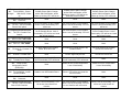
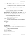
CDMA StarTAC/TIMEPORT PROGRAMMING CARD
1
2
TO
Enter NAM 1
programming mode
Enter Your
Phone Number
3 Enter AMPS System
ENTER
PRESS 7, 4, 6, 6, 3, #, 1, FCN, FCN
PHONE DISPLAYS
Enter MIN
Use the keypad to enter all ten digits of
your phone number and press “STO”
Sample Number:
312-555-1212
Enter _ _ _ _ _. Press “STO”
Sample Number:
11111
Enter _ _ _ _ _. Press “STO”
Sample Number:
11111
ID (Analog)
4 Enter Digital
System ID
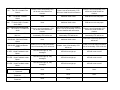
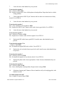
TDMA StarTAC/TIMEPORT PROGRAMMING CARD
1
TO
Enter programming
mode
ENTER
PRESS “#”, Carrier System ID,
“#”, “*”, “SEND”
PRESS “*”
PHONE DISPLAYS
Nam 1 Prog
*= Yes #= No
Security
Code _ _ _ _ _ _
Enter Security Code
PRESS 0, 0, 0, 0, 0, 0
(This is the code that is in the phone
when it is shipped out of the factory)
PRESS “SEND”
Phone displays its ESN
(Electronic Serial Number)
2
3
4
5
Enter Phone Number
Phone #
__________
ENTER Entire Phone Number
(_ _ _) _ _ _ - _ _ _ _
PRESS “SEND”
Mercedes Benz Technical Manual for Telephone v4.6
NAM Program Begins
Date: 09/01/2004
1.0 General Section
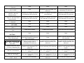
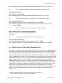
CDMAv.60c PROGRAMMING CARD
1
TO
Enter Programming Mode
2
Selecting NAM
3
Enter Phone Number
4
Enter AMPS system ID
5
Enter CDMA system ID
6
Finalizing Programming
ENTER
PRESS 7, 4, 6, 6, 3, #, MENU,
MENU
CHOSE “SELECT” for NAM 1
PHONE DISPLAYS
Nam 1
Nam 2
MIN: 0000000000
INSERT 10-digit MIN through the
keypad and SELECT “OK”
(This is the customers cellular
number)
SCROLL down to AMPS Sys ID
and INSERT number then SELECT
“OK”
(AMPS data provided by carrier)
INSERT CDMA Sys ID then
SELECT “OK”
(CDMA data provided by carrier)
SELECT “DONE” then PRESS the
“END” key
IMSI
CDMA Sys ID:
MIN:
Main Menu
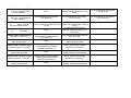
TDMA v.60t PROGRAMMING CARD
1
TO
Enter Programming Mode
2
Enter Security Code
3
Enter Phone Number
4
Finalizing Programming
ENTER
PHONE DISPLAYS
PRESS #, Carrier System I.D., #,*,
Enter Security Code
“SEND”
----------------PRESS 0,0,0,0,0,0, and SELECT
ESN (Hex)
“OK”
(This is the factory default code)
SCROLL down to MIN: ---------------- IMSI
and INSERT 10-digit MIN through
the keypad and SELECT “OK”
(MIN is the customer cell number)
SELECT “DONE” (the handset
Main Menu
display will turn off temporarily)
Mercedes Benz Technical Manual for Telephone v4.6
Date: 09/01/2004
1.0 General Section
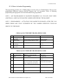
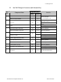
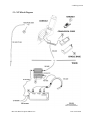
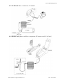
1.3 Telephone System Components
The Motorola integrated telephone packages from MY2000 thru MY2005 consist of the following
components:
KEY: ‘1’ = PSE/D2B Components, ‘2’ = CP/MOST Components, ‘3’ = MHI/MOST Components
Antenna Switch (Splitter for SL only) – 1, 3
Coil Cord – 1, 2
Compensator – 1, 2, 3
Communication Platform Module - 2
D2B Wiring – 1
MOST Wiring – 2, 3
Motorola Cellular Telephone
(CDMA, TDMA or GSM with Mercedes-Benz Logo and Software) – 1, 2, 3
Multiple Handset Interface Module (MHI) - 3
Phone Cradle – 1, 2, 3
Portable Support Electronics Module (PSE) – 1
Voice Recognition Module (Optional Kit on Some Models) – 1, 2, 3
“Y” Cable – 1
The components of the telephone package between MY2000 and MY2001 are not compatible or
interchangeable due to the technological differences between the two systems. The MY2000 telephone
package is 800MHz only and cannot support the MY2001 telephone package components, which are
1900MHz in addition to the 800MHz.
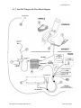
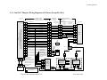
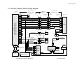
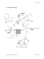
Figures 1 thru 10 of the StarTAC/Timeport Block Diagram provide illustrations of the telephone
package component layout for the MY2000/01 S-Class (W220, C215), CLK (A208, C208), E-Class
(W210, S210), SL (R129), C-Class (W203), SLK (R170), and M-Class (W163) MY2000 & MY2001
Mercedes-Benz when utilizing the PSE module and D2B system. Figures 1 thru 9 of the v60 Block
Diagram provide illustrations of the telephone package component layout for the aforementioned
Classes reflecting MY2002/04 when utilizing the PSE module and D2B system. Figures 1 thru 6, 9 of
the CP Block Diagram provide illustrations of the telephone package component layout for the
MY2003/04 E-Class (BR211) and MY2004 S-Class (BR220), CL-Class (BR215) and Maybach
(BR240) when utilizing the CP module and MOST system. Figures 1 thru 6, 8, 9 of the MHI Block
Diagram provide illustrations of the telephone package component layout for all the MY2005 vehicle
chassis when supported by the MHI module and MOST system. These drawings and components are
discussed in greater detail beginning with section 3.1.
1.3.1 Phone Cradle
The MY2001 phone cradle is similar in appearance to the MY2000 phone cradle, except that it has been
modified to accommodate the Motorola Timeport™ handset. The MY2002/04 phone cradles clip into
the cradle base for full integration and is removable allowing for ease of use in private mode. The cradle
Mercedes Benz Technical Manual for Telephone v4.6
Date: 09/01/2004
1.0 General Section
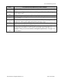
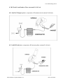
version accepting the v60s utilizes two different ‘cradle clips’ depending on the phone used. One cradle
clip is used for the v60s handset, whereas a second cradle clip is used for both the v60i and v60x. The
pictures below point out the physical differences between the two clips. The MY2005 phone cradle has
a couple of differences compared to the prior ones. The MY2005 cradle is not removable; instead the
phone is snapped into the cradle for a secure fit, while using the fully integrated hands-free system. The
MY2005 cradle also contains a circuit board enabling a more intelligent connection between the
handset and the vehicle system. All the phone cradles are located between the front seats in the console.
1.3.2 Microphone
The microphone for MY2000/04 is located in the headliner near the rear view mirror and is labeled as
number 10 in each block diagram. MY2005 vehicles use a microphone array consisting of four
microphones evenly distributed across the headliner in front of the windshield and is labeled as number
10 in the MHI block diagram. For all the vehicles, the microphone will be installed at the factory. A
connector in the headliner attaches to the microphone assembly (microphone array for MY2005) and
ties into the Mercedes-Benz pre-wired harness. Vehicles utilizing the PSE module and D2B system will
connect to Motorola’s “y” cable before connecting to the PSE, vehicles utilizing either the CP or MHI
modules and MOST system will run directly to the respective control modules.
1.3.3A Portable Support Electronics Module (PSE)
The PSE box for the telephone package contains the software and associated electronics that are
responsible for processing the voice data as well as the central processing of data to allow the integration
of the phone with the vehicle. MY00, MY01, and MY02/04 PSE boxes are not the same internally.
MY00 is 800MHz analog/digital. MY01 and MY02/04 are both 1900MHz digital in addition to 800MHz
analog/digital. Only MY02/04 PSE supports either Timeport or v.60 systems with appropriate coil cord,
cradle, and handset.
Note: Labeling for the MY00 and MY01 PSEs will have white barcodes. Labeling for the MY02/04
PSEs will have blue barcodes.
1.3.3B Communication Platform Module (CP)
The CP modules were first introduced on the MY2003 E-Class (BR211) and later on the MY2004 SMercedes Benz Technical Manual for Telephone v4.6
Date: 09/01/2004
1.0 General Section
Class (BR220), CL-Class (BR215) and Maybach (BR240). The CP module for the telephone package
contains the PSE box supporting the software and associated electronics for the integration of the handset
to the vehicle. The CP module also contains the Tele-Aid module supporting the emergency notification
system in the vehicle.
1.3.3C Multiple Handset Interface Module (MHI)
MHI was introduced on the MY2005 vehicles across all chassis except for Maybach, which still utilizes
the CP module. The MHI module is similar to the PSE module in that it supports the portable phone’s
initial integration for the telephone package into the vehicle system, but communicates using the MOST
vehicle bus instead of the D2B vehicle bus. The MHI system is designed to be forwards-compatible with
future portable phones (the user only needs to change the cradle in order to upgrade to new portables in
the future). The MHI also has integrated software to perform the Hands-free Audio function, such that the
Microphone Array Module from AKG is no longer required to be part of the system.
1.3.4 Handset
A Motorola Digital handset is used for the telephone system. Although the Digital handset is available as
a portable phone sold separately by various vendors, it will not interface with the Mercedes-Benz vehicle.
Only handsets that are part of the telephone package will interface with the Mercedes-Benz vehicle. They
can also be used as a portable cellular phone when not interfacing with the vehicle. The three types of
handsets available for the telephone package are digital TDMA, CDMA or GSM, which will be
determined by the customer and/or carrier availability. Refer to section 1.2.1 and 1.2.2 of this manual and
the appropriate user manual for a full description of each handset and a detailed explanation of CDMA,
TDMA and GSM technologies. The customer will have the option to purchase more than one handset
that can also be integrated with the same vehicle, but only one handset can be integrated at any time.
1.3.5 Compensator
The compensator is used to "compensate" for the small amount of power that is lost as a result of the
extra RF cable needed to send or receive the signal through the vehicles antenna. The compensator is not
a booster when in digital or analog modes. Refer to section 4 for a complete layout and description of the
RF path, which includes the compensator.
~ The voice activation feature interfaces with the telephone package. It is treated as a separate system and
is not covered in this manual.
Mercedes Benz Technical Manual for Telephone v4.6
Date: 09/01/2004
2.0 Wiring Section
2.0 Electrical Connectors and Wiring Section
Table of Contents
2.1 __ StarTAC/Timeport Layout, Connectors and Schematics
2.2
V.60 Layout, Connectors and Schematics
2.3
CP Layout and Schematics
2.4
MHI Layout and Schematics
Mercedes Benz Telephone Manual v4.6
Date: 09/01/2004
2.0 Wiring Section
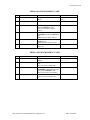
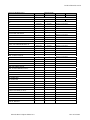
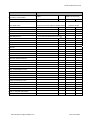
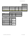
2.1
StarTAC/Timeport Connectors and Schematic Key
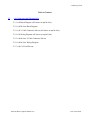
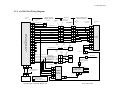
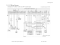
2.1.1 StarTAC/Timeport Block Diagram (All classes except M class)
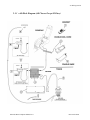
2.1.2 StarTAC/Timeport M-class Block Diagram
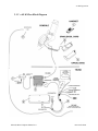
2.1.3 StarTAC/Timeport Y Cable Connector Pin-out (all classes except M class)
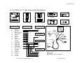
2.1.4 StarTAC/Timeport Wiring Diagram (all classes except M class)
2.1.5 StarTAC/Timeport M-class Y Cable Connector Pin-out
2.1.6 StarTAC/Timeport M-class Wiring Diagram
2.1.7 StarTAC/Timeport Coil Cord Pin-out
Mercedes Benz Telephone Manual v4.6
Date: 09/01/2004
2.0 Wiring Section
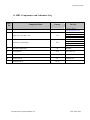
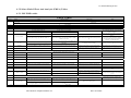
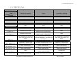
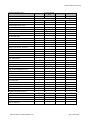
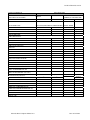
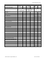
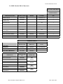
2.1
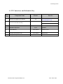
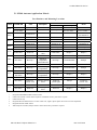
StarTAC/Timeport Connectors and Schematic Key
Ref.
No.
Component Name
Page Reference
Desc.
Pin-out
MY00 StarTAC Handset
3
21
MY01/02 Timeport Handset
3
21
1
2
Coil Cord
3
Part No.
Reference Website:
www.mbusaphones.com
Q6820464: (W220, C215, R129,
W203, R170, W163)
Q6820465: (A208, C208, W210,
S210)
MY00: Q6820459
MY01/02: Q6820649
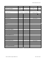
N/A
21
Cradle
11
N/A
MY00 Single Band Compensator
12
17, 19
MY00: Q6820525
MY01/02 Dual Band Compensator
12
17, 19
MY01/02: Q6820657
4
“Y” Cable (All Classes except M Class)
5
17
N/A
M Class “Y” Cable
6
Portable Support Electronics (PSE)
19
12
Single Band Antenna Switch
7
17, 19
Q6820468
MY00: Q6820469
MY01/02: Q6820672
MY00: Q6820460
MY01/02: Q6820648
17, 19
MY00: Q6820430
17, 19
MY01/02: Q6820652
N/A
Dual Band Antenna Switch
8
Antenna Splitter (SL only)
N/A
17
MY01/02: Q6820675
9
GPS Splitter Coax (M-Class Only)
N/A
19
MY00: Q6820470
MY01/02: Q6820674
10
Microphone
12
17, 19
Mercedes Benz Telephone Manual v4.6
See Mercedes-Benz Dealer
Date: 09/01/2004
2.0 Wiring Section
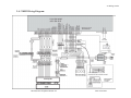
2.1.1 StarTAC/Timeport Block Diagram (All Classes Except M Class)
Mercedes Benz Telephone Manual v4.6
Date: 09/01/2004
2.0 Wiring Section
2.1.2 StarTAC/Timeport M-Class Block Diagram
Mercedes Benz Telephone Manual v4.6
Date: 09/01/2004
2.0 Wiring Section
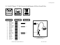
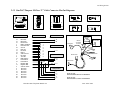
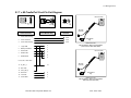
2.1.3 StarTAC/Timeport “Y” Cable Connector Pin Out Diagrams (All Classes Except M-Class)
13
1
25
14
1
6
25
14
13
1
7
14
PSE Connector
Main Harness Connector
Compensator
PSE Connector
Main Harness
Connector
Compensator
1
2
3
4
5
6
7
8
9
10
11
12
13
14
15
16
17
18
19
20
21
22
23
24
25
RX GND
Not Used
Battery Negative
Battery Positive
Not Used
TX Audio
Battery Feedback
External Power
Antenna Switch
Not Used
Data Out
Not Used
D2B Wakeup
MIC GND
MIC Audio
Battery Positive
Battery Negative
Data In
Not Used
Not Used
Manual Test
Not Used
Ground
Audio Ground
Not Used
1
7
3
4
5
6
21
8
9
10
11
12
13
14
15
16
17
18
19
20
2
22
23
24
25
Mercedes Benz Telephone Manual v4.6
1
4
Compensator
5
Main Harness
Connector
3
2
PSE Connector
Motorola "Y" Cable
MB Part #Q6820468, Motorola Part #SKN4979A
(All Classes Except "M" Class)
Date: 09/01/2004
2.0 Wiring Section
2.1.4 StarTAC/Timeport Wiring Diagram (All Classes Except M-Class)
Motorola "Y" Cable
25 PIN MALE
DSUB
25 PIN FEMALE
DSUB
P.S.E.
(Portable Support Electronics) Module
Model Year 2000: Q6820460, SYN0234C (All Classes)
Model Year 2001: Q6820648, SYN8738C (All Classes)
14
OUT
IN
OUT
22 AWG MIC GND
OUT
ICU
10 PIN
MODULAR
PLUG
15 PIN PHONE
JACK
15 PIN PHONE
CONNECTOR
22 AWG MIC AUDIO
21
24 AWG
MANUAL TEST
2
2
10
10
5
7
7
24 AWG
BATT FEEDBACK
21
21
1
1
4
4
8
8
24 AWG
EXT. PWR
8
8
3
3
14
14
23
23
GND
23
23
2
2
10
10
11
11
24 AWG
DATA OUT
11
11
4
4
6
6
12
12
24 AWG
NOT USED
12
12
5
5
18
18
24 AWG
DATA IN
18
18
6
24
24
24 AWG
AUDIO GND
24
24
1
1
24 AWG
RX AUDIO
1
6
6
24 AWG
TX AUDIO
6
2
2
NC
7
7
5
5
22 AWG RED
5
5
10
10
22 AWG RED
10
10
19
19
22 AWG BROWN
19
19
20
20
22 AWG BROWN
20
20
22
22
22 AWG GREEN
22
22
25
25
25
25
9
9
ANTENNA SWITCH
9
9
13
13
D2B WAKEUP
13
13
3
3
NEGATIVE BATT
3
3
17
17
NEGATIVE BATT
17
17
16
16
POSITIVE BATT
16
16
4
POSITIVE BATT
15
15
NC
Motorola Supplied D2B
Fiber Optic Cable
Q6820425, SKN4949A (R129)
Q6820432, SKN4960A
(W220, W463)
Q# is Mercedes-Benz Part No.
S# is Motorola Part No.
7
6
15
15
7
7
9
9
1
8
8
8
8
6
9
9
1
1
3
3
2
2
1
1
2
2
3
3
4
4
5
5
M
F
MINI-UHF
Mercedes Benz Telephone Manual v4.6
Portable
Phone
To
Antenna
MINI-UHF
To ICU
M
Prewired
F
To
E-Call Unit
To
E-Call Unit
Battery
4
+
4
F
F
M
M
14 PIN MALE
14 PIN FEMALE
Shaded Box indicates
Motorola Supplied Component
5
7
Prewired
Q6820466, SKN4981A (S210)
IN
Q6820465, SKN4975A (A208, C208, S210,
W210, W463)
10 PIN MODULAR
JACK (PREWIRED)
14
15
Q6820508, SKN4984A (C215)
OUT
14
Motorola Coil Cord
Q6820464, SKN4974A (C215, R129, R170,
W203, W220)
25 PIN FEMALE
(PREWIRED)
21
Q6820467, SKN4982A (W210)
IN
25 PIN MALE
CONNECTOR
15
4
IN
14
MB Prewire
Q6820468, SKN4979A
(All Classes Except M Class)
Antenna Switch
Digital
Compensator
Q6820652, SYN8711A
(A208, CL203, R170,
S203, S210, W203,
W220)
Q6820657
(all classes)
MINIUHF
SYN8486A
F
M
MINI-UHF
M
F
F
M
KL 31
TEL PSE PIN 9
E-CALL UNIT
Antenna Splitter
Q6820675,
SYN8711A (R129)
KL 15
MINIUHF
To Antenna
M
F
MINIUHF
SL-Class
Only
F
M
MINIUHF
To Antenna
Motorola Confidential and Proprietary
Date: 09/01/2004
2.0 Wiring Section
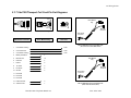
2.1.5 StarTAC/Timeport M-Class “Y” Cable Connector Pin Out Diagrams
Pin
A
AB
P.S.E.
25
14
PSE Connector
1
10
1
6
7
14
10 Pin Modular Jack
14
15
21
7
8
23
11
12
18
24
1
6
13
4
16
3
17
9
MIC GND
MIC Audio
Manual Test
Battery Feedback
External Power
Ground
Data Out
Not Used
Data In
Audio Ground
RX Audio
TX Audio
D2B Wakeup
Positive Batt
Positive Batt
Negative Batt
Negative Batt
Antenna Switch
2
5
10
19
20
22
25
Not Used
Not Used
Not Used
Not Used
Not Used
Not Used
Not Used
10 Pin Modular Jack
2 Pin Male
10
1
3
2
4
5
6
7
8
9
3 Pin Male Connector
MY 2001
D2B Coupler
A
B
Mercedes Benz Telephone Manual v4.6
Pin
A
Compensator
D2B Connector
PSE Connector
2 Pin Male Connector
A B C
13
1
1 Pin Female
Connector
Compensator
MY 2000
D2B Connector
MY 2001
1 Pin Female
Connector
1 Pin Female
2 Pin Male
Connector
A
3 Pin Male
10 AMP
C
B
PSE Connector
3 Pin Male Connector
10 Pin Modular
Jack
D2B Connector
A
Compensator
1
2
3
4
5
Motorola "Y" Cable
Model Year 2000:
MB Part #Q6820469, Motorola Part #SKN5000A
Model Year 2001:
MB Part #Q6820672, Motorola Part #SKN6327A
Date: 09/01/2004
2.0 Wiring Section
2.1.6 StarTAC/Timeport M-Class Wiring Diagram
Motorola "Y" Cable
Q6820672, SKN6327A
25 PIN MALE
DSUB
P.S.E.
(Portable Support Electronics) Module
Model Year 2000: Q6820460, SYN0234C
Model Year 2001: Q6820648, SYN8738C
25 PIN FEMALE
DSUB
OUT
IN
OUT
OUT
IN
OUT
ICU
10 PIN
MODULAR
PLUG
10 PIN MODULAR
JACK (PREWIRED)
15 PIN PHONE
CONNECTOR
15 PIN PHONE
JACK
14
14
22 AWG MIC GND
15
15
22 AWG MIC AUDIO
21
21
24 AWG
MANUAL TEST
10
10
10
10
5
7
7
24 AWG
BATT FEEDBACK
1
1
1
1
4
4
8
8
24 AWG
EXT. PWR
3
3
3
3
14
14
23
23
GND
2
2
2
2
10
10
11
11
24 AWG
DATA OUT
4
4
4
4
6
6
12
12
24 AWG
NOT USED
5
5
5
5
18
18
24 AWG
DATA IN
6
6
6
24
24
24 AWG
AUDIO GND
7
7
1
1
24 AWG
RX AUDIO
8
6
6
24 AWG
TX AUDIO
9
2
2
NC
5
5
NC
10
10
NC
19
19
NC
20
20
NC
22
22
NC
A
B
ANTENNA SWITCH
NC
25
9
9
13
13
D2B WAKEUP
NEGATIVE BATT
3
3
17
17
16
16
4
4
7
6
15
15
7
7
9
9
8
8
8
8
8
9
9
9
1
1
3
3
2
2
1 PIN
MALE
A
Prewired
A
Portable
Phone
To
Antenna
MINI-UHF
3 PIN
MALE
25
NC
5
7
1 PIN
FEMALE
M
Prewired
F
Prewired
3 PIN
FEMALE
HIRSCHMANN
NEGATIVE BATT
C
C
B
B
To E-Call Unit
To ICU
M
-
Coax Cable to E-Call
Q6820673, SKN6328a
Battery
POSITIVE BATT
POSITIVE BATT
A
+
A
F
Motorola Supplied D2B
Fiber Optic Cable
IN
10 PIN MODULAR
PLUG (PREWIRED)
10 PIN
MODULAR
JACK
2 PIN MALE
Q# is Mercedes-Benz Part No.
S# is Motorola Part No.
Shaded Box indicates
Motorola Supplied Component
MINI-UHF
M
14 PIN MALE
14 PIN FEMALE
IN
Motorola Coil Cord
Q6820464, SKN4974A
MB Prewire
To Antenna
1
1
2
2
3
3
4
4
5
5
M
F
MINI-UHF
KL 31
TEL PSE PIN 9
Antenna Switch
Q6820652, SYN8711A
Digital
Compensator
E-CALL UNIT
GPS
Splitter/Amplifier
KL 15
Q6820657,
SYN8486A
MINI-UHF
F
M
M
F
F
M
MINI-UHF
Coax Cable to GPS Splitter/Amplifier
Q6820674, SKN6329A
MINI-UHF
Motorola Confidential and Proprietary
Mercedes Benz Telephone Manual v4.6
Date: 09/01/2004
2.0 Wiring Section
2.1.7 StarTAC/Timeport Coil Cord Pin Out Diagrams
Pin 1
PUSH
TOP
10 Pin Modular
Plug
Pin 1
15 Pin Phone Connector
Pin 10
10 Pin Modular Plug
Center Pin
Mini-UHF
Connector
Coax Connector
15 Pin Phone Connector
10 Pin Modular Plug
PUS
H
Coax Mini-UHF
Connector
TOP
15 Pin Phone
Connector
Motorola Coil Cord
MB Part #Q6820464, Motorola Part #SKN 4974A
(C215, R129, R170, W163, W203, W220)
Coax Outer Housing
Coax
2
Coax Center Pin
Coax
3
Coax Outer Housing
Coax
4
Battery Feedback
1
5
Manual Test
10
6
Data Out
4
7
Data In
6
8
TX Audio
9
9
RX Audio
8
10
Ground
2
11
Not Used
12
Not Used
10 Pin Modular
Plug
Mini-UHF
Connector
15 Pin Phone
Connector
PUS
H
TOP
1
13
Not Used
14
External Power
3
15
Audio Ground
7
Mercedes Benz Telephone Manual v4.6
Motorola Coil Cord
MB Part #Q6820465, Motorola Part #SKN 4975A
(A208, C208, S210, W210, W463)
Date: 09/01/2004
2.0 Wiring Section
Table of Contents
2.2 ___ v.60 Connectors and Schematic Key
2.2.1 v.60 Block Diagram (All classes except M class)
2.2.2 v.60 M-class Block Diagram
2.2.3 v.60 Y Cable Connector Pin-out (all classes except M class)
2.2.4 v.60 Wiring Diagram (all classes except M class)
2.2.5 v.60 M-class Y Cable Connector Pin-out
2.2.6 v.60 M-class Wiring Diagram
2.2.7 v.60 Coil Cord Pin-out
Mercedes Benz Telephone Manual v4.6
Date: 09/01/2004
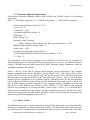
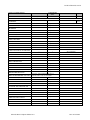
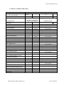
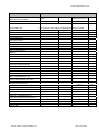
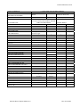
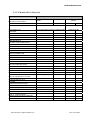
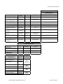
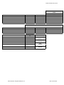
2.1 v.60 Connectors and Schematic Key
Page Reference
Ref.
No.
1
Component Name
Part No.
Desc.
Pin-out
MY02 v.60 Handset
3
28
v.60 Coil Cord Cradle Assembly
11
28
Timeport Coil Cord Cradle Assembly
11
21
N/A
N/A
12
24, 26
Q6820657
24
Q6820468
26
Q6820672
12
24, 26
Q6820754
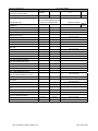
2
3.
v.60 Cradle Base
4
MY02 Dual Band Compensator
“Y” Cable (All Classes except M Class)
5
Reference Website:
www.mbusaphones.com
Q6820770: (W220, C215, R129,
W203, R170, W163)
Q6820771: (A208, C208, W210,
S210, W463)
Q6820722: (W220, C215, R129,
W203, R170, W163)
Q6820723: (A208, C208, W210,
S210, W463)
Q6820768
N/A
M Class “Y” Cable
6
Portable Support Electronics (PSE)
7
Dual Band Antenna Switch
N/A
24,26
Q6820652
8
Antenna Splitter (SL only)
N/A
24
Q6820675
9
Microphone
12
24, 26
See Mercedes-Benz Dealer
2.0 Wiring Section
2.1.1 v.60 Block Diagram (All Classes Except M Class)
Mercedes Benz Telephone Manual v4.6
Date: 09/01/2004
2.0 Wiring Section
2.1.2 v.60 M-Class Block Diagram
Mercedes Benz Telephone Manual v4.6
Date: 09/01/2004
2.0 Wiring Section
2.1.3 v.60 “Y” Cable Connector Pin Out Diagrams (All Classes Except M-Class)
13
1
25
14
1
6
25
14
13
1
7
14
PSE Connector
Main Harness Connector
Compensator
PSE Connector
Main Harness
Connector
Compensator
1
2
3
4
5
6
7
8
9
10
11
12
13
14
15
16
17
18
19
20
21
22
23
24
25
RX GND
Not Used
Battery Negative
Battery Positive
Not Used
TX Audio
Battery Feedback
External Power
Antenna Switch
Not Used
Data Out
Not Used
D2B Wakeup
MIC GND
MIC Audio
Battery Positive
Battery Negative
Data In
Not Used
Not Used
Manual Test
Not Used
Ground
Audio Ground
Not Used
1
7
3
4
5
6
21
8
9
10
11
12
13
14
15
16
17
18
19
20
2
22
23
24
25
Mercedes Benz Telephone Manual v4.6
1
4
Compensator
5
Main Harness
Connector
3
2
PSE Connector
Motorola "Y" Cable
MB Part #Q6820468, Motorola Part #SKN4979A
(All Classes Except "M" Class)
Date: 09/01/2004
2.0 Wiring Section
2.1.4 v.60 Wiring Diagram (All Classes Except M-Class)
Motorola "Y" Cable
25 PIN MALE
DSUB
25 PIN FEMALE
DSUB
P.S.E.
(Portable Support Electronics) Module
Model Year 2002: Q6820754, SYN9266A
OUT
15
15
21
21
24 AWG
MANUAL TEST
2
2
10
10
12
12
7
7
24 AWG
BATT FEEDBACK
21
21
1
1
2
2
8
8
24 AWG
EXT. PWR
8
8
3
3
3
3
23
23
GND
23
23
2
2
1
1
11
11
24 AWG
DATA OUT
11
11
4
4
4
4
12
12
24 AWG
NOT USED
12
12
5
5
5
5
18
18
24 AWG
DATA IN
18
18
6
6
17
17
24
24
24 AWG
AUDIO GND
24
24
7
7
15
15
1
1
24 AWG
RX AUDIO
1
1
8
8
16
16
6
6
24 AWG
TX AUDIO
6
6
9
9
14
14
2
2
NC
7
7
14
15
OUT
ICU
15
17 PIN PHONE
CONNECTOR
5
22 AWG RED
5
5
1
1
10
22 AWG RED
10
10
3
3
19
19
22 AWG BROWN
19
19
2
2
20
20
22 AWG BROWN
20
20
22
22
22 AWG GREEN
22
22
25
25
25
25
To
Antenna
MINI-UHF
Prewired
9
9
ANTENNA SWITCH
9
9
13
13
D2B WAKEUP
13
13
3
3
NEGATIVE BATT
3
3
17
17
NEGATIVE BATT
17
17
16
POSITIVE BATT
16
16
POSITIVE BATT
4
Motorola Supplied D2B
Fiber Optic Cable
Q6820425, SKN4949A (R129)
Q6820432, SKN4960A
(W220, W463)
Q# is Mercedes-Benz Part No.
S# is Motorola Part No.
Shaded Box indicates
Motorola Supplied Component
Mercedes Benz Telephone Manual v4.6
To ICU
M
Portable
Phone
Not Used
6,7,8,9,10,11,13
Prewired
F
To
E-Call Unit
To
E-Call Unit
Battery
4
+
4
F
F
M
M
14 PIN MALE
14 PIN FEMALE
Q6820466, SKN4981A (S210)
IN
10 PIN
MODULAR
PLUG
5
Q6820508, SKN4984A (C215)
OUT
10 PIN MODULAR
JACK (PREWIRED)
14
10
Q6820467, SKN4982A (W210)
IN
17 PIN PHONE
JACK
22 AWG MIC AUDIO
4
IN
Q6820770, SYN8952A (C215, R129, R170,
W203, W220)
Q6820771, SYN8953A (A208, C208, S210,
W210, W463)
25 PIN FEMALE
(PREWIRED)
22 AWG MIC GND
16
OUT
25 PIN MALE
CONNECTOR
14
14
IN
Motorola Coil Cord/Cradle
MB Prewire
Q6820468, SKN4979A
(All Classes Except M Class)
1
1
2
2
3
3
4
4
5
5
M
F
MINI-UHF
Antenna Switch
Digital
Compensator
Q6820652, SYN8711A
(A208, CL203, R170,
S203, S210, W203,
W220)
Q6820657
(all classes)
MINIUHF
SYN8486A
F
M
MINI-UHF
M
F
F
M
KL 31
TEL PSE PIN 9
E-CALL UNIT
Antenna Splitter
Q6820675,
SYN8711A (R129)
KL 15
MINIUHF
To Antenna
M
F
MINIUHF
SL-Class
Only
F
M
MINIUHF
To Antenna
Motorola Confidential and Proprietary
Date: 09/01/2004
2.0 Wiring Section
2.1.5 v.60 M-Class “Y” Cable Connector Pin Out Diagrams
AB
Pin
A
P.S.E.
1
25
14
PSE Connector
1
10
6
7
14
1 Pin Female
Connector
10 Pin Modular Jack
14
15
21
7
8
23
11
12
18
24
1
6
13
4
16
3
17
9
MIC GND
MIC Audio
Manual Test
Battery Feedback
External Power
Ground
Data Out
Not Used
Data In
Audio Ground
RX Audio
TX Audio
D2B Wakeup
Positive Batt
Positive Batt
Negative Batt
Negative Batt
Antenna Switch
2
5
10
19
20
22
25
Not Used
Not Used
Not Used
Not Used
Not Used
Not Used
Not Used
10 Pin Modular Jack
2 Pin Male
10
1
3
2
4
5
6
7
8
9
3 Pin Male Connector
MY 2002
D2B Coupler
A
B
Mercedes Benz Telephone Manual v4.6
Pin
A
Compensator
D2B Connector
PSE Connector
2 Pin Male Connector
A B C
13
1
Compensator
MY 2002
1 Pin Female
Connector
1 Pin Female
2 Pin Male
Connector
A
3 Pin Male
10 AMP
C
B
PSE Connector
3 Pin Male Connector
10 Pin Modular
Jack
D2B Connector
A
Compensator
1
2
3
4
5
Motorola "Y" Cable
Model Year 2002:
MB Part #Q6820672, Motorola Part #SKN6327A
Date: 09/01/2004
2.0 Wiring Section
2.1.6 v.60 M-Class Wiring Diagram
Motorola "Y" Cable
Q6820672, SKN6327A
25 PIN MALE
DSUB
P.S.E.
(Portable Support Electronics) Module
Model Year 2002: Q6820754, SYN9266A
25 PIN FEMALE
DSUB
10 PIN
MODULAR
JACK
2 PIN MALE
OUT
OUT
OUT
IN
OUT
ICU
17 PIN PHONE
JACK
14
15
15
22 AWG MIC AUDIO
21
21
24 AWG
MANUAL TEST
10
10
10
10
12
12
7
7
24 AWG
BATT FEEDBACK
1
1
1
1
2
2
8
8
24 AWG
EXT. PWR
3
3
3
3
3
3
23
23
GND
2
2
2
2
1
1
11
11
24 AWG
DATA OUT
4
4
4
4
4
4
12
12
24 AWG
NOT USED
5
5
5
5
5
5
18
18
24 AWG
DATA IN
6
6
6
6
17
17
24
24
24 AWG
AUDIO GND
7
7
7
7
15
15
1
1
24 AWG
RX AUDIO
8
8
8
8
16
16
6
6
24 AWG
TX AUDIO
9
9
9
9
14
14
2
2
NC
5
5
NC
1
1
10
10
NC
3
3
19
19
NC
2
2
20
20
NC
22
22
NC
25
25
NC
A
B
1 PIN
FEMALE
ANTENNA SWITCH
1 PIN
MALE
A
3 PIN
MALE
9
9
13
13
D2B WAKEUP
3
3
NEGATIVE BATT
17
17
16
16
NEGATIVE BATT
To
Antenna
MINI-UHF
Prewired
3 PIN
FEMALE
B
B
A
A
Coax Cable to E-Call
Q6820673, SKN6328a
+
Q# is Mercedes-Benz Part No.
S# is Motorola Part No.
Shaded Box indicates
Motorola Supplied Component
MINI-UHF
M
KL 31
1
2
3
3
4
4
5
5
M
F
MINI-UHF
Prewired
To E-Call Unit
14 PIN MALE
2
F
M
F
1
M
Antenna Switch
Q6820652, SYN8711A
Digital
Compensator
TEL PSE PIN 9
E-CALL UNIT
KL 15
M
Q6820657,
SYN8486A
MINI-UHF
F
F
F
MINI-UHF
M
MINI-UHF
Motorola Confidential and Proprietary
Mercedes Benz Telephone Manual v4.6
Portable
Phone
HIRSCHMANN
To ICU
C
Battery
POSITIVE BATT
POSITIVE BATT
4
Prewired
A
C
Motorola Supplied D2B
Fiber Optic Cable
IN
17 PIN PHONE
CONNECTOR
14
14 PIN FEMALE
IN
10 PIN
MODULAR
PLUG
10 PIN MODULAR
JACK (PREWIRED)
22 AWG MIC GND
4
IN
Motorola Cradle/Coil Cord
Q6820770, SYN8952A
MB Prewire
10 PIN MODULAR
PLUG (PREWIRED)
Date: 09/01/2004
2.0 Wiring Section
2.1.7 v.60 Cradle/Coil Cord Pin Out Diagram
Pin 1
Pin 1
Phone Connector
CRADLE
Pin
17
Phone Connector
Phone Connector
Pin 10
10 Pin Modular Plug
10 Pin Modular Plug
Center Pin
Coax Connector
Coax Mini-UHF
Connector
1
Coax Outer Housing
Coax
2
Coax Center Pin
Coax
3
Coax Outer Housing
Coax
1
Logic GND
2
Battery Feedback
3
External B+
4
RS232 TXD
5
RS232 RXD
2
CRADLE
Mini-UHF
Connector
10 Pin Modular
Plug
Motorola Coil Cord
MB Part #Q6820770, Motorola Part #SYN 8952A
(C215, R129, R170, W163, W203, W220)
1
3
Phone Connector
4
6
5
CRADLE
6,7,8,9,10,11 Not Used
10
12
D_SEL_0
13
Not Used
14
OPT_SEL_2
15
RX Audio
8
16
TX Audio
9
17
Audio GND
7
Mercedes Benz Telephone Manual v4.6
Mini-UHF
Connector
10 Pin Modular
Plug
Motorola Coil Cord
MB Part #Q6820771, Motorola Part #SYN 8953A
(A208, C208, S210, W210, W463)
Date: 09/01/2004
2.0 Wiring Section
Table of Contents
2.3 ___CP Layout and Schematics
2.3.1 CP Block Diagram for MY2003/04 E-Class (BR211) and MY2004 S-Class (BR220), CLClass (BR215) and Maybach (BR240).
2.3.2 CP Schematic
Mercedes Benz Telephone Manual v4.6
Date: 09/01/2004
2.0 Wiring Section
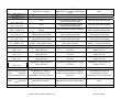
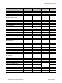
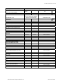
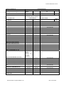
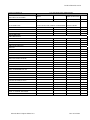
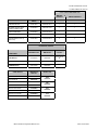
2.3 CP Connectors and Schematic Key
Ref.
No.
1
Component Name
MY03/04 CP Supported v.60 Handset
Part No.
Pin-out
28
28
Reference Website:
www.mbusaphones.com
Q6820883: MY04 (215, 220, 240)
2
v.60 Coil Cord Cradle Assembly
3
v.60 Cradle Base
4
Dual Band Compensator
5
Wiring Harnesses
40, 40, MOST
Vehicle Pre-wire
6
Communication Platform (CP)
40, 40, MOST
A2408201526
9
Microphone Array
Mercedes Benz Telephone Manual v4.6
Q6820833: MY03 (211)
N/A
Q6820768
24, 26
Q6820657
24, 26
See Mercedes-Benz Dealer
Date: 09/01/2004
2.0 Wiring Section
2.3.1 CP Block Diagram
Mercedes Benz Telephone Manual v4.6
Date: 09/01/2004
2.0 Wiring Section
2.3.2 CP Wiring Diagram
Mercedes Benz Telephone Manual v4.6
Date: 09/01/2004
2.0 Wiring Section
Table of Contents
2.4 ___MHI Layout and Schematics
2.4.1 MHI Block Diagram for MY2005 Vehicles
2.4.2 MHI Schematic
Mercedes Benz Telephone Manual v4.6
Date: 09/01/2004
2.0 Wiring Section
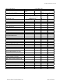
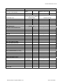
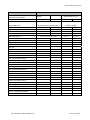
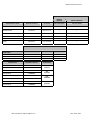
2.4 MHI Components and Schematic Key
Ref.
No.
1
Component Name
Pin-out
MY05 MHI Supported ‘V’ Series Handsets
28
Cradle v60i, v60s, v600, v710
N/A
Cradle Base (Contact Plate)
N/A
2
3
Part No.
Reference Website:
www.mbusaphones.com
V60i – Q6820988
V60s – Q6820925
V600 – Q6820919
V710 – Q6820920
A23082005011 (171, 230)
A2038201311 (203, 209, 211)
A2158200611 (215)
A2208201511 (220)
4
Dual Band Compensator
24
Q6820829
5
Wiring Harness
N/A
Vehicle Pre-wire
6
Multiple Handset Interface (MHI)
8
Antenna Switch
9
Microphone Array
Mercedes Benz Telephone Manual v4.6
MOST
24
24, 26
Q6820936
A2208271842
See Mercedes-Benz Dealer
Date: 09/01/2004
2.0 Wiring Section
2.4.1 MHI Block Diagram
Mercedes Benz Telephone Manual v4.6
Date: 09/01/2004
2.0 Wiring Section
2.4.2 MHI Wiring Diagram
Mercedes Benz Telephone Manual v4.6
Date: 09/01/2004
3.0 Installation Section
3.0 Installation Section
Table of Contents
3.1 MY2000 Installation Instructions
D2B Fiber Optic Configuration
All Classes
Cellular Telephone Configuration
C-Class
M-Class with Navigation
M-Class without Navigation
SLK-Class
Voice Activated Cellular Telephone Configuration
CL-Class
CLK-Class
CLK-Class Cabriolet
E-Class
E-Class Wagon
S-Class
S-Class Updated
SL-Class
Mercedes Benz Telephone Manual v4.6
Date: 09/01/2004
3.0 Installation Section
MY2001 Installation Instructions
D2B Fiber Optic Configuration
All Classes
Cellular Telephone Configuration
C-Class
M-Class with Navigation
M-Class Without Navigation
SLK-Class
Voice Activated Cellular Telephone Configuration
CL-Class
CLK-Class
CLK-Class Cabriolet
E-Class
E-Class Wagon
S-Class
SL-Class
Mercedes Benz Telephone Manual v4.6
Date: 09/01/2004
4.0 Troubleshooting Section
4.0 Troubleshooting Section
Table of Contents
4.1 __V.60 Characteristics/Differences From Timeport
4.2 __RF Path From Handset Thru Antenna/E-call Unit
4.2.1__ StarTAC/Timeport
4.2.2__ V.60
4.2.3__ CP
4.2.4__ MHI
4.3 __Failure Mode Effects And Analysis (FMEA) Tables
4.3.1__ PSE FMEA
4.3.2__ CP FMEA
4.3.3__ MHI FMEA
4.4 __Preliminary Troubleshooting Procedure
4.4.1__ Handset Keypad Or Display Problems
4.4.2__ No Battery Charging While Plugged Into The Vehicle
4.4.3__ Phone Does Not Power Up
4.4.4 No Keypad Tones And/Or No Incoming Audio In Hands-free Mode From Vehicle
Speakers
4.4.5__ Static During Calls And/Or Dropped Calls
4.4.6 No Handset Audio Or Landline Cannot Hear Mobile On Handset Or Mobile Cannot
Hear Landline On Handset
4.4.7
No Hands-free Transmit Audio/Called Party Cannot Hear You
4.4.8
No SVC Indicator Stays On
4.4.9
Complete Loss Of Vehicle System Audio
Mercedes Benz Telephone Manual v4.6
Date: 09/01/2004
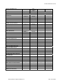
4.0 Troubleshooting Section
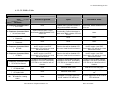
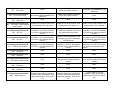
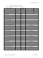
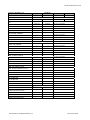
4.1 v.60 Characteristics/Differences from Timeport
ID #
001
002
003
004
005
006
007
008
009
010
011
012
013
014
015
v.60 Characteristics/Differences from Timeport
Power down phone from phone key while it is powering up. Power back up and no
DTMF keypress tones in vehicle and in the phone (when flip opened).
Unknown caller ID is in phone incoming call list as unknown or private but shows
nothing in HU calls list.
Speed dial a number from phonebook containing a variable number will keep
displaying dialing until call is ended. The 1 st call after ending call will not complete.
Must be ended and next call will complete.
Phone in call plug into vehicle with flip open and speaker phone soft key does not work
1 st time. SPEAKER PHONE SOFT KEY IS NOT INTENDED FOR VEHICLE USE.
SEE NOTE ON PAGE 10 OF VEHICLE MANUAL.
Phone in autolock, connected, unlock phone, power down, power up, HU displays
Ready for 8 seconds before Lock screen, during 8 seconds phone can be accessed from
HU.
Phone is disconnected and reconnected before disconnect tones(less than 3 seconds
between connections). Phone loses communication with PSE until power cycled. HU
Displays still 'Tel. not plugged in'.
Phonebook/Calls/Last Calls blinks 2 times quickly whenever lists are updated due to
incoming or outgoing calls.
If user has the same phone number stored with a different area code it will not matched
to name tag correctly. Proper number will be dialed but the first name tag entry
alphabetically will be displayed.
Call failed/redial – Call failed, redial?, screen will not be displayed on head unit as with
Timeport. Phone will automatically go into redial mode and head unit will display
dialing for up to 4 minutes. Call can be ended from head unit or phone at any time.
After 4 minute the phone redial mode will timeout and head unit will go back to Ready
screen.
Phone book quantity – Timeport has maximum of 99 entries and v.60 has possible 400
entries. The head units can only display up to 99 entries. If phone book entry location is
greater than 99 it will not be displayed or selectable on head unit but will be available
from the phone. Under this condition it would appear as if head unit and phone are not
synchronized.
Digits entered on head unit with phone flip open will display on phone and does not get
cleared when cleared on head unit, must be cleared on phone.
v.60 takes much longer to power up and down which sometimes appears that head unit
and phone are out of sync.
Pause dialing – pause character is entered from head unit but wait character is entered
into phone. Operation is identical to Timeport but symbol in phone is different.
DTMF tones heard in phone speaker when flip open and in an active call
911 automatically dialed from location 1 when phone locked and location 1
speed/turbo dialed.
Mercedes Benz Telephone Manual v4.6
Date: 09/01/2004
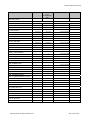
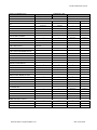
4.0 Troubleshooting Section
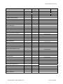
ID #
016
017
018
019
020
021
022
v.60 Characteristics/Differences from Timeport
Cannot partially enter lock code on the phone and then try to complete entry from the
HU.
v.60 phone uses 4-digits unlock code in stand alone portable mode and first 3 digits
only in vehicle mode.
Variable dialing can only be initiated from the v.60 phone.
Phone charging time changed from 8 hours to 5 minutes when phone is connected to an
unpowered car.
Text and voice mail message alert tones are defaulted to Vibe pulse setting. This will
eliminate the vehicle system audio muting during message receipt.
Reminder tones are defaulted Off. User must turn on which will result in vehicle
system audio muting during a reminder event.
v.60 presently uses a fast switching half duplex audio processing technique. The user
may experience an inability to easily break in on the other party when they are
speaking or if they are in an environment with high background noise. See page 3 of
vehicle manual.
Mercedes Benz Telephone Manual v4.6
Date: 09/01/2004
4.0 Troubleshooting Section
4.2 RF Path From Handset Thru Antenna/E-Call Unit
4.2.1 StarTAC/Timeport [phone, compensator, RF antenna switch, antenna/E-call unit]
4.2.2 v.60 RF Path [phone, compensator, RF antenna splitter, antenna/E-call unit]
Mercedes Benz Telephone Manual v4.6
Date: 09/01/2004
4.0 Troubleshooting Section
4.2.3 CP RF Path [phone, compensator, CP module]
4.2.4 MHI RF Path [phone, cradle base, compensator, RF antenna switch, E-call unit]
Mercedes Benz Telephone Manual v4.6
Date: 09/01/2004
4.0 Troubleshooting Section
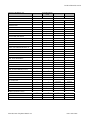
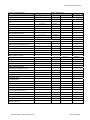
4.3 Failure Mode Effects And Analysis (FMEA) Tables
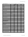
4.3.1 PSE FMEA table
FMEA TABLE
PSE Pin
1
Signal
Open
Phone will not turn off/on via head unit TEL key
receive audio
Audio _In/On_Off
2
3
4
5
Ground chassis
A+
6
Audio out
Short to Ground
No transmit or receive hands free audio
No receive audio in hands free mode
Key on: phone powers down when connected; key off:
h
d NOThUSED
No adverse effect
Blows fuse to tel system
NOT USED
Ground (white) noise on landline
No adverse effect
No adverse effect
No transmit audio in hands free
7
8
Short to 12v
in HF; loud
transmit
ground noise;
audio OK
No transmit or receive audio in HF
No transmit audio from vehicle hands free mic
No visible effect
No visible effect
TDMA: No adverse effect
Battery will not charge; poor talk time outside car
Battery will not charge; poor talk time outside car; battery
will have excess drain
CDMA: Phone powers down and can not be powered
up
Disconnecting phone battery shuts down phone
Pour reception and likely no ability to call out; no ant
drive in R129
No charging; phone will operate but on main battery only
until dead
TDMA: download takes 8X longer (5 – 40 sec.)
Pour reception and likely no ability to call out; no ant
drive in R129
Phone powers on/off constantly @ 6 sec. intervals
No vehicle power to phone; no charging
9
Ant drive
11
SCI RXD
Phone powers on/off constantly @ 6 sec. intervals
13
D2B wakeup
PSE sleeps; no ring start
14
Ground chassis
No adverse effect
No adverse effect
15
Mic Hi
No transmit audio in hands free
No transmit audio in hands free
12
NOT USED
Ring does not start; phone powers on/off @ 2 sec.
intervals
Notes
Blow fuse on sourcing feed
No adverse effect
50Hz TDMA buzz on landline
Battery Feedback
B+ out
No
PSE permanently damaged (no transmit audio
after original CDMA test; replaced and retested
CDMA, no problem)
Battery indicates charging despite no charging
going on
Pin 8 will be at 4.4v (min charge voltage) Can
verify charging circuit function by comparing
pins 7&8 on PSE with phone connected. 8
should be 1.4v greater than pin 7
No charging, switches to battery
“Charging” will not be indicated in FCN4 mode
No adverse effect on ant sw; power antenna always
up in R129
CDMA: Phone permanently damaged; TDMA No
damaging effect but no operation with H/U
Open and short will cause antenna to go to Tele
Aid at all times
PSE is turning on phone via PSE dial in an
attempt wakeup portable
Ring will never start
Blow fuse on sourcing feed
Microphone shield
TDMA/ CDMA: No transmit audio
16
A+
No adverse effect
Blows fuse to telephone system
No adverse effect
17
Ground chassis
No adverse effect
No adverse effect
Blow fuse on sourcing feed
18
SCI TXD
Phone cycles on/off constantly @ 18 sec. Intervals
(TDMA) 6 sec. (CDMA)
Phone cycles on/off constantly @ 18 sec. Intervals
(TDMA) 6 sec. (CDMA)
NOT USED
TDMA remains on but no function with head unit;
CDMA: powers down and will not power up
20
Ground chassis
No adverse effect
No adverse effect
Blow fuse on sourcing feed
Shield for data lines to R1-45. Not ground
source
MANUAL TEST
Fast battery outline flash & “charging disabled” on
TDMA FCN4
TDMA: powers off then on and enters test mode
21
“Externally powered” on CDMA function 4
CDMA: powers off then can not be powered on
Fast battery outline flash & “charging disabled” on
TDMAFCN4
CDMA: Powers down and then when powered up
NAM is erased including ESN
PSE supplies 33k ohms to ground to tell phone
to charge; must power down to exit test mode if
shorted
Blow fuse on sourcing feed
Ground source to StarTAC. With this open
StarTAC gets ground through coax
19
22
NOT USED
23
Ground chassis
No adverse effect
No adverse effect
24
Ground analog
TDMA: heavy pulse noise, no transmit audio, will not
recognize phone is connected to coil cord
CDMA: Slow oscillating noise, no transmit audio, will
not recognize phone is connected to coil cord
TDMA: Heavy noise pulse; H/U will not shut down if in
a call
CDMA: Slow oscillating noise; H/U will not shut down if
in a call
NOT USED
25
If 4 & 16 are last, gross system failure
Mercedes Benz Telephone Manual v4.6
Blow fuse on sourcing feed
Date: 09/01/2004
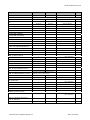
4.0 Troubleshooting Section
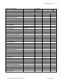
4.3.2 CP FMEA Table
BLOCK
Item
Shorted to ground.
Open.
Shorted to Vbatt.
J1-Telephone Connector/ PIN-1
/ KL31-GND
None.
J1-Telephone Connector/ PIN-2
/ KL30-Power Vbatt.
System fuse will open. Loss of
functionality. MRS/CAN/MOST DTS
will be set.
Unstable GND. Potential increase in
audio noise and EMC emissions
TCU will lose power. Loss of
functionality. Potential increases in
Audio noise/ EMC emission. DTC will
be set.
J1-Telephone Connector/ PIN-3
/ Reserved.
None.
None.
None.
J1-Telephone Connector/ PIN-4
/ Reserved.
None.
None.
None.
Function
J1-Telephone Connector/ PIN-5
/ BT RxD-.
J1-Telephone Connector/ PIN-6
/ BT RxD+.
J1-Telephone Connector/ PIN-7
/ BT CTS-Flow Control.
J1-Telephone Connector/ PIN-8
/ BT Shield-GND.
J1-Telephone Connector/ PIN-9
/ BT Audio GND.
J1-Telephone Connector/ PIN10 / BT Audio Rx - Analog
Audio .
Unable to receive messages from
the BT module. Loss of BT
functionality. DTC will be set. Hand
Set will not function.
Unable to receive messages from
the BT module. Loss of BT
functionality. DTC will be set. Hand
Set will not function.
Unable to receive and/or transmit
messages. Loss of BT functionality.
DTC will be set. Hand Set will not
function.
System fuse will open. Loss of
functionality. MRS/CAN/MOST/DTS
will be set
None.
Unable to receive and/or transmit
messages. Loss of BT functionality.
DTC will be set. Hand Set will not
function.
Unable to receive messages from
the BT module. Loss of BT
functionality. DTC will be set. Hand
Set will not function.
Unable to receive messages from
the BT module. Loss of BT
functionality. DTC will be set. Hand
Set will not function.
Unable to receive and/or transmit
messages. Loss of BT functionality.
DTC will be set. Hand Set will not
function.
None.
Additional Audio noise.
PCB trace or wire may open.
None.
Additional Audio noise.
Loss of BT Audio signal. DTC will be
set.
None.
Unreliable or no Audio signal from
the BT module. DTC will be set.
No Audio signal from the BT module.
DTC will be set.
Mercedes Benz Telephone Manual v4.6
Receive Line will be disabled. DTC
will be set. Hand Set will not function.
Receive Line will be disabled. DTC
will be set. Hand Set will not function.
Date: 09/01/2004
J1-Telephone Connector/ PIN11 / KL31-GND.
None.
Unstable GND. Potential increases in
Audio noise/ EMC emission.
System fuse will open. Loss of
functionality. MRS/CAN/MOST DTS
will be set.
J1-Telephone Connector/ PIN12 / KL30-Power Vbatt.
System fuse will open. Loss of
functionality. MRS/CAN/MOST DTS
will be set.
Unstable GND. Potential increases in
Audio noise/ EMC emission.
None.
J1-Telephone Connector/ PIN13 / Reserved.
None.
None.
None.
J1-Telephone Connector/ PIN14 / BT On/Off - On/Off Control
for BT module.
Unable to turn Off BT module. Loss
of functionality. DTC will be set.
Unable to turn On BT module. Loss
of functionality. DTC will be set.
Unable to turn On BT module. Loss
of functionality. DTC will be set.
J1-Telephone Connector/ PIN15 / BT TxD-.
J1-Telephone Connector/ PIN16 / BT TxD+.
J2-Telephone Connector/ PIN17 / BT RTS-Flow Control.
Unable to transmit messages to the
BT module. Loss of BT functionality.
DTC will be set. Hand Set will not
function.
Unable to transmit messages to the
BT module. Loss of BT functionality.
DTC will be set. Hand Set will not
function.
Unable to transmit and/or receive
messages. Loss of BT functionality.
DTC will be set. Hand Set will not
function.
Unable to transmit and/or receive
messages. Loss of BT functionality.
DTC will be set. Hand Set will not
function.
Unable to transmit messages to the
BT module. Loss of BT functionality.
DTC will be set. Hand Set will not
function.
Unable to transmit messages to the
BT module. Loss of BT functionality.
DTC will be set. Hand Set will not
function.
Unable to transmit and/or receive
messages. Loss of BT functionality.
DTC will be set. Hand Set will not
function.
BT will lose functionality. DTC will be
set. Hand Set will not function.
Unable to transmit messages to the
BT module. Loss of BT functionality.
DTC will be set.
J1-Telephone Connector/ PIN18 / Reserved.
None.
None.
None.
J1-Telephone Connector/ PIN19 / Reserved.
None.
None.
None.
J1-Telephone Connector/ PIN20 / BT Audio Tx-Analog Audio.
None.
No Audio signal to the BT module.
DTC will be set. Hand Set will not
function.
No Audio signal to the BT module.
DTC will be set. Hand Set will not
function.
J1-Telephone Connector/ PIN21 / Reserved.
None.
None.
None.
J1-Telephone Connector/ PIN22 / Reserved.
None.
None.
None.
J1-Telephone Connector/ PIN23 / MOST Wake-up
TCU unable to enter Sleep mode.
Excessive current during ignition off
condition. Main battery will be drain
faster than expected. DTC will be
set.
TCU unable to enter Sleep mode.
Excessive current during ignition off
condition. Main battery will be drain
faster than expected. DTC will be
set.
TCU will wake-up on CAN
messages, unable to wake-up on
MOST signal. MOST DTC will be
set.
J1-Telephone Connector/ PIN24 / Tel On/Off/WU - Phone/
Charger/
SIM On/Off; / Wakeup.
Improper or no operation of the
Portable Phone and/or Charger,
and/or SIM Card Reader, and/or
Wake-up circuitry. DTC will be set.
Improper or no operation of the
Portable Phone and/or Charger,
and/or SIM Card Reader, and/or
Wake-up circuitry. DTC will be set.
Hand Set will not function.
Improper or no operation of the
Portable Phone and/or Charger,
and/or SIM Card Reader, and/or
Wake-up circuitry. DTC will be set.
J1-Telephone Connector/ PIN25 / Reserved.
None.
None.
None.
No communication on the Portable
Phone. Loss of functionality. DTC
will be set.
Improper and/or no communication
on the Portable Phone. Loss of
functionality. DTC will be set. Hand
Set will not function.
No communication on the Portable
Phone. Loss of functionality. DTC will
be set.
No communication on the Portable
Phone. Loss of functionality. DTC
will be set.
Improper and/or no communication
on the Portable Phone. Loss of
functionality. DTC will be set. Hand
Set will not function.
J1-Telephone Connector/ PIN28 / Mic2 In GND - NOT USED.
None.
None.
None.
J1-Telephone Connector/ PIN29 / Mic2 In+ - NOT USED.
None.
None.
None.
J1-Telephone Connector/ PIN30 / Tel Audio Tx - Portable TX
Audio.
No Audio signal to the Portable
Phone. DTC will be set.
Unreliable or no Audio signal to the
Portable Phone.
No Audio signal to the Portable
Phone. DTC will be set.
J1-Telephone Connector/ PIN31 / Tel GND - Portable GND.
None.
Unreliable GND for the Portable
Phone. Signal may be lose.
No Audio signal to the Portable
Phone. DTC will be set.
No power for the Portable Phone.
Loss of functionality. DTC will be set.
No power for the Portable Phone.
Loss of functionality. DTC will be set.
None.
None.
Unable to turn On/Off compensator.
Loss of functionality.
Unable to turn On compensator.
Loss of functionality.
Unable to turn Off Portable Phone.
Unable to turn On/Off Portable
Phone. DTC will be set. Hand Set
will not function.
None.
J1-Telephone Connector/ PIN35 / Reserved.
None.
None.
None.
J1-Telephone Connector/ PIN36 / Tel RxD - RXD for Portable
Phone/ DSC Downlink.
No communication on the Portable
Phone. Loss of functionality. DTC
will be set. Hand Set will not
function.
No communication on the Portable
Phone. Loss of functionality. DTC will
be set. Hand Set will not function.
No communication on the Portable
Phone. Loss of functionality. DTC
will be set. Hand Set will not
function.
J1-Telephone Connector/ PIN26 / Tel TxD - TXD for Portable
Phone/ DSC uplink.
J1-Telephone Connector/ PIN27 / Tel RTS - Portable Flow
Control.
J1-Telephone Connector/ PIN32 / Portable Phone Power.
J1-Telephone Connector/ PIN33 / Comp On/Off Compensator On/Off
(ECE/USA).
J1-Telephone Connector/ PIN34 / Tel On/Off/WU - On/Off
Control Portable.
No communication on the Portable
Phone. Loss of functionality. DTC will
be set.
J1-Telephone Connector/ PIN37 / Tel CTS - Portable Flow
Control.
J1-Telephone Connector/ PIN38 / Tel Shield - Portable
Shield.
J1-Telephone Connector/ PIN39 / Tel Audio GND - Portable
Audio GND.
J1-Telephone Connector/ PIN40 / Tel Audio Rx - Portable RX
Audio.
J2-Telematic Connector/ PIN-1 /
Mic1 In+.
J2-Telematic Connector/ PIN-2 /
SIM Shield - SIM Card Reader
Shield.
J2-Telematic Connector/ PIN-3 /
SIM On/Off - SIM Card Reader
On/Off.
No communication on the Portable
Phone. Loss of functionality. DTC
will be set. Hand Set will not
function.
No communication on the Portable
Phone. Loss of functionality. DTC
will be set. Hand Set will not function.
No communication on the Portable
Phone. Loss of functionality. DTC
will be set. Hand Set will not
function.
None.
Additional Audio noise.
PCB trace or wire may open.
None.
Additional Audio noise.
PCB trace or wire may open.
No communication on the Portable
Phone. Loss of functionality. DTC
will be set. Hand Set will not
function.
No Audio signal. Loss of
functionality. DTC will be set.
No communication on the Portable
Phone. Loss of functionality. DTC will
be set. Hand Set will not function.
No Audio signal. Loss of
functionality. DTC will be set.
No communication on the Portable
Phone. Loss of functionality. DTC
will be set. Hand Set will not
function.
No Audio signal. Loss of
functionality. DTC will be set.
None.
Additional Audio noise.
PCB trace or wire may open. DTC
will be set.
Unable to turn On SIM Card Reader.
Loss of functionality. DTC will be set.
Unable to turn On/Off SIM Card
Reader. Loss of functionality. DTC
will be set.
Unable to turn Off SIM Card Reader.
Loss of functionality. DTC will be set.
J2-Telematic Connector/ PIN-4 /
IC LED - Visual Feedback Inside
Button.
LED will never light up, may
damaged.
LED will never light up.
LED will never turn Off.
J2-Telematic Connector/ PIN-5 /
TD LED - Visual Feedback Inside
Button.
LED will never light up, may
damaged.
LED will never light up.
LED will never turn Off.
J2-Telematic Connector/ PIN-6 /
EC LED - Visual Feedback Inside
Button.
LED will never light up, may
damaged.
LED will never light up.
LED will never turn Off.
None.
None.
None.
J2-Telematic Connector/ PIN-8 /
Reserved.
None.
None.
None.
J2-Telematic Connector/ PIN-9 /
Reserved.
None.
None.
J2-Telematic Connector/ PIN-7
/ Reserved.
J2-Telematic Connector/ PIN-10
/ Reserved.
None.
None.
None.
J2-Telematic Connector/ PIN-11
/ Mic1 In GND.
None.
Improper/or no Audio signal.
Possibility to lose functionality. DTC
will be set.
No Audio signal. Loss of
functionality. DTC will be set.
J2-Telematic Connector/ PIN-12
/ SIM RTS - SIM Card
Presence Detect.
Improper/or no detection of presence
of the SIM Card. DTC will be set.
Improper/or no detection of presence
of the SIM Card.
Improper/or no detection of presence
of the SIM Card. DTC will be set.
J2-Telematic Connector/ PIN-13
/ SIM CTS - SIM Card Reader
Detect Override.
Improper/or no detection of presence
of the SIM Card. DTC will be set.
Improper/or no detection of presence
of the SIM Card. DTC will be set.
Improper/or no detection of presence
of the SIM Card. DTC will be set.
J2-Telematic Connector/ PIN-14
/ Reserved.
None.
None.
None.
J2-Telematic Connector/ PIN-15
/
NOT USED.
None.
None.
None.
J2-Telematic Connector/ PIN-16
/ H-Button 2
None.
None.
None.
J2-Telematic Connector/ PIN-17
/ Mute
Unable to MUTE Radio.
Unable to MUTE Radio.
Radio will be MUTED constantly.
J2-Telematic Connector/ PIN-18
/
NOT USED.
None.
None.
None.
J2-Telematic Connector/ PIN-19
/ Trunk - Discrete Input.
During Engineering Test will cause
Test code to Reset DTC will be set.
Loss of functionality.
None.
Unable to maintain Engineering Test.
DTC will be set.
Improper/or no Audio Signal from the
Service Operator. Loss of
functionality. DTC will be set.
No Audio Signal from the Service
Operator. Loss of functionality. DTC
will be set.
No Audio Signal from the Service
Operator. Loss of functionality. DTC
will be set.
No messages from the CAN
interface. Loss of diagnostic. DTC
will be set.
No communication on the SIM Card
lines. Loss of functionality. DTC will
be set.
No communication on the SIM Card
lines. Loss of functionality. DTC will
be set.
No communication on the CAN lines.
Loss of functionality. DTC will be set.
No messages from the CAN
interface. Lost of diagnostic. DTC will
be set.
No communication on the SIM Card
lines. Loss of functionality. DTC will
be set.
No communication on the SIM Card
lines. Loss of functionality. DTC will
be set.
J2-Telematic Connector/ PIN20 / Spkr In - Audio Signal
from AGW.
J2-Telematic Connector/ PIN-21
/ D-CAN Hi - Diagnosis CAN.
J2-Telematic Connector/ PIN-22
/ SIM RxD - DSC Downlink.
J2-Telematic Connector/ PIN-23
/ SIM TxD - DSC Uplink.
J2-Telematic Connector/ PIN-24
/ IC BUT - Switch.
DTC will be set. No activation.
No communication on the SIM Card
lines. Loss of functionality. DTC will
be set.
No communication on the SIM Card
lines. Loss of functionality. DTC will
be set.
Unable to activate the IC call. DTC
will be set.
DTC will be set. Unable to turn Off.
J2-Telematic Connector/ PIN-25
/ TD BUT - Switch.
DTC will be set. No activation.
DTC will be set. No activation.
DTC will be set. Unable to turn Off.
J2-Telematic Connector/ PIN-26
/ EC BUT - Switch.
DTC will be set. No activation.
DTC will be set. No activation.
DTC will be set. Unable to turn Off.
J2-Telematic Connector/ PIN-27
/ BPS I/F RX - Control Data.
NOT USED.
None.
None.
None.
J2-Telematic Connector/ PIN-28
/ BPS I/F ENA - I/F Control.
NOT USED.
None.
None.
None.
J2-Telematic Connector/ PIN-29
/ Cntrl Relay - NOT USED.
None.
None.
None.
J2-Telematic Connector/ PIN-30
/ Spkr In+ - Audio Signal from
AGW.
NOT USED.
None.
None.
None.
J2-Telematic Connector/ PIN-31
/ D-CAN Lo - Diagnosis CAN.
NOT USED.
None.
None.
None.
J2-Telematic Connector/ PIN-32
/ D-CAN Shield - Shielding.
None.
No messages from the CAN
interface. Lost of diagnostic.
No Shield for the CAN. No
messages from the CAN interface.
Lost of diagnostic. DTC will be set.
J2-Telematic Connector/ PIN-33
/ Eng I/F Rx.
Unable to provide Engineering Test.
DTC will be set.
Unable to provide Engineering Test.
DTC will be set.
Unable to provide Engineering Test.
DTC will be set.
J2-Telematic Connector/ PIN-34
/ Eng I/F Tx.
Unable to provide Engineering Test.
DTC will be set.
Unable to provide Engineering Test.
DTC will be set.
Unable to provide Engineering Test.
DTC will be set.
J2-Telematic Connector/ PIN-35
/ Crash - Digital Crash Input
(200 Bd).
No Crash signal will be receive. Loss
of functionality. DTC will be set.
No Crash signal will be receive. Loss
of functionality. DTC will be set.
No Crash signal will be receive. Loss
of functionality. DTC will be set.
J2-Telematic Connector/ PIN-36
/ BPS I/F TX - Control Data.
NOT USED.
None.
None.
None.
J2-Telematic Connector/ PIN-37
/ BPS + - Backup Power Line.
Unable to activate the BPS device.
Loss of functionality. DTC will be set.
Unable to activate the BPS device.
Loss of functionality. DTC will be set.
Unable to turn Off the BPS device.
Loss of functionality. DTC will be set.
J2-Telematic Connector/ PIN-38
/ BPS + - Backup Power Line.
Unable to activate the BPS device.
Loss of functionality. DTC will be set.
Unable to activate the BPS device.
Loss of functionality. DTC will be set.
Unable to turn Off the BPS device.
Loss of functionality. DTC will be set.
J2-Telematic Connector/ PIN-39
/ Spkr Out- Audio Ground to
Center Speaker.
None.
Unstable GND for the Speaker.
Distortions and/or noise on the Audio
Signal.
No Audio signals on the Speaker.
DTC will be set.
J2-Telematic Connector/ PIN-40
/ Spkr Out+ - Audio Signal to
Center Speaker.
No Audio signals on the Speaker.
DTC will be set.
No Audio signals on the Speaker.
DTC will be set.
No Audio signals on the Speaker.
DTC will be set.
FAKRA Single Connector/ PIN
1/
GPS+ - GPS RF
Signal & Antenna Power.
No GPS RF Signal, no Antenna
Power. Loss of functionality. DTC will
be set.
FAKRA Single Connector/ PIN
2/
GPS GND.
None.
No GPS RF Signal, no Antenna
Power. Loss of functionality. DTC will
be set.
Unstable GND for the GPS &
Antenna. Signal may be lost. DTC
will be set.
FAKRA Triple Connector/ PIN 1/
Main Antenna-Phone RF.
Main Antenna will be grounded. No
RF signal from/to Main Antenna.
DTC will be set.
No RF signal from/to Main Antenna.
DTC will be set.
FAKRA Triple Connector/ PIN 2/
Main Antenna GND.
None.
Unstable GND for the Main Antenna.
Signal may be distorted.
FAKRA Triple Connector/ PIN 3/
Portable Antenna - Phone RF.
Portable Antenna will be grounded.
No RF signal from/to Portable
Antenna. DTC will be set.
No RF signal from/to Portable
Antenna. DTC will be set.
FAKRA Triple Connector/ PIN 4/
Portable Antenna GND.
None.
Unstable GND for the Portable
Antenna. Signal may be distorted.
FAKRA Triple Connector/ PIN 5/
Backup Antenna - Phone RF.
Backup Antenna will be grounded.
No RF signal from/to Portable
Antenna. DTC will be set.
No RF signal from/to Backup
Antenna. DTC will be set.
FAKRA Triple Connector/ PIN 6/
Backup Antenna GND.
None.
Unstable GND for the Portable
Antenna. Signal may be distorted.
4.0 Troubleshooting Section
4.3.3 MHI FMEA Table
BLOCK
Item
Shorted to Battery
Open.
Shorted to Ground
None
None
Attached Fuse will blow.
Attached Fuse will blow.
None
Attached Fuse will blow.
None
None
increased current through J1-4
increased current through J1-3
None
Lower immunity to EMI.
None
None
None
None
None
None
None
None
None
None
None
None
None
Lower immunity to EMI. May have
additional noise on uplink audio.
Lower immunity to EMI. May have
additional noise on uplink audio.
None
None
Function
DIAG_TXD J1-1
DIAG_RXD J1-2
Ground J1-3
Ground J1-4
No Connect J1-5
HUC Data Shield J1-6
No Connect J1-7
No Connect J1-8
No Connect J1-9
CP_SHIELD J1-10
MIC SHIELD J1-11
MIC- J1-12
CP_MIC_OUT J1-13
HUC_SKRIN+ J1-14
HUC_MICOUT+ J1-15
HUC_MICOUT- J1-16
HUC_BATT J1-17
HUC_GROUND J1-18
Attached Fuse will blow.
Attached Fuse will blow.
Loss or degradation of Microphone
(audio uplink) performance may
occur.
No Downlink audio from ATX.
Degradation of downlink audio
quality. Lower noise immunity.
Degradation of uplink audio quality.
Lower noise immunity.
Degradation of uplink audio quality.
Lower noise immunity.
None
Attached Fuse will blow.
Mercedes Benz Telephone Manual v4.6
Loss or degradation of Microphone
(audio uplink) performance. Module will
go into Re-flash Mode. "No Phone" will
be displayed.
No Downlink audio from ATX.
Degradation of downlink audio quality.
Lower noise immunity.
Degradation of uplink audio quality.
Lower noise immunity.
Degradation of uplink audio quality.
Lower noise immunity.
Loss of cradle functionality, loss of
communication with Cradle
MHI module may go into re-flash mode
and will cause excess current draw.
None
None
Loss or degradation of Microphone
(audio uplink) performance may
occur.
No Downlink audio from ATX.
Degradation of downlink audio
quality. Lower noise immunity.
Degradation of uplink audio quality.
Lower noise immunity.
Degradation of uplink audio quality.
Lower noise immunity.
Fuse will blow.
None
Date: 09/01/2004
Attached Fuse will blow.
HUC_AUDIO Shield J1-19
V_BATTERY J1-20
V_BATTERY J1-21
HUC_TXD- J1-22
HUC_TXD+ J1-23
None
None
None
None
Lower immunity to EMI. May have
additional noise on uplink and downlink
audio.
Higher current will be seen on J1-21
Higher current will be seen on J1-20
Loss of cradle functionality, loss of
communication with Cradle
Loss of cradle functionality, loss of
communication with Cradle
None
7.5 amp Fuse will Blow
7.5 amp Fuse will Blow
Fuse or 0 ohm jumper will blow.
Fuse or 0 ohm jumper will blow.
MOST ring will not be able to
wakeup.
Loss of cradle functionality, loss of
communication with Cradle
Loss of cradle functionality, loss of
communication with Cradle
Degradation of downlink audio
quality. Lower noise immunity.
degradation of cellular performance
Degradation of audio quality on
uplink. DTC 670
Degradation of audio quality on
uplink. DTC 672
Degradation of audio quality on
uplink. DTC 674
Loss of cradle functionality, loss of
communication with Cradle
Loss of cradle functionality, loss of
communication with Cradle
Degradation of downlink audio quality.
Lower noise immunity.
degradation of cellular performance
Degradation of audio quality on uplink.
DTC 670
Degradation of audio quality on uplink.
DTC 672
Degradation of audio quality on uplink.
DTC 674
MOST bus kept on, excess current
draw, may cause battery drain.
Loss of cradle functionality, loss of
communication with Cradle
Loss of cradle functionality, loss of
communication with Cradle
Degradation of downlink audio
quality. Lower noise immunity.
degradation of cellular performance
Degradation of audio quality on
uplink. DTC 671
Degradation of audio quality on
uplink. DTC 673
Degradation of audio quality on
uplink. DTC 675
Degradation of audio quality on
uplink. DTC 676
Degradation of audio quality on uplink.
DTC 676
Degradation of audio quality on
uplink. DTC 677
FAKRA Single Connector/
PIN 1/
Bluetooth
Signal & Antenna Power.
No Bluetooth RF Signal, no
Antenna Power. Loss of
functionality. DTC 6A2 will be set.
No Bluetooth RF Signal, no Antenna
Power. Loss of functionality. DTC 6A1
will be set.
No Bluetooth RF Signal, no
Antenna Power. Loss of
functionality. DTC 6A1 will be set.
FAKRA Single Connector/
PIN 2/
Bluetooth
GND.
Attached Fuse will blow.
Degradation in Bluetooth Performance
None
MOST_WAKE J1-24
HUC_RXD+ J1-25
HUC_RXD- J1-26
HUC_SPKRIN- J1-27
Compensator J1-28
MIC1 J1-29
MIC2 J1-30
MIC3 J1-31
MIC4 J1-32
Mercedes Benz Telephone Manual v4.6
MOST ring will not be able to wakeup.
Date: 09/01/2004
4.0 Troubleshooting Section
4.4 Preliminary Troubleshooting Procedure
1.
Verify the Problem
Assure that the problem is not due to operator error. It is important that the operator is familiar
with how the telephone package functions. Refer to the owner’s manual for specific phone
function capability.
2.
Verify that the Handset is the Correct One for the Customer’s Coverage Area
Handset part numbers are carrier dependent. If the part number of the handset does not
correspond with the carrier specific number, the phone will not function properly and will appear
to be defective. Refer to the parts department to find the correct handset type (CDMA or
TDMA), and carrier specific part number for the customer’s carrier preference.
The part numbers can also be found on the web at: http://www.mbusaphones.com. This site is
provided by Motorola and is intended for dealer use only. The site is password protected. Enter
"mbusa" for the "User Name" entry, and "k2option" for the "Password", both entries need to
be in lower case letters, and then select “O.K.”.
3.
Assure that the Handset is Programmed Correctly
Assure that the phone is properly programmed and activated. If the customer is switching cell
service from analog to digital, inform the carrier that the new phone is digital to avoid activation
problems. Make a test call to verify that the carrier has activated the phone, and that it has been
programmed correctly.
4.
Assure that the System is Installed Properly
Inspect the installation of the system. Assure that all component connections and wiring
connectors are properly connected. Assure that the Compensator has not been installed
backwards (reversed in the antenna line).
5.
Check Applicable Fuses
Assure that all fuses are good. In addition to checking the fuses for the phone system, other
vehicle systems which interface with the telephone package might have a blown fuse, such as the
radio, etc, which would affect the operation of the phone functions. If a fuse is blown, determine
the cause to eliminate the problem from reoccurring.
6.
Signal Quality
If the problem is poor signal quality, assure that it is not a carrier problem. Eliminate the
possibility of a cell site malfunction or other carrier related anomaly by calling the customer’s
carrier to verify that they are not experiencing technical problems. A bad signal could also be the
result of the operator being outside of, or on the edge of, a carrier provider’s coverage area.
Mercedes Benz Telephone Manual v4.6
Date: 09/01/2004
4.0 Troubleshooting Section
Tall buildings, hills or mountains, valleys, inside buildings, etc, can "block" the RF signal and
give a false impression that the telephone package is defective. Some examples would be, inside
the center of a building with few or no windows, an under-ground parking facility where the
signal is virtually blocked in both directions (receive/transmit) by the structure, driving through
tunnels, etc.
7.
Inspect the Coil Cord
Assure that the phone to coil cord connection is good. Closely inspect the male connection at the
end of the coil cord and the female connection on the bottom end of the handset for missing or
damaged pins, corrosion, etc.
8.
Assure that all Components are Receiving Power and have a good Ground Path
Refer to the electrical diagrams in section 4 to assure that power and ground is present for each
component.
9.
Inspect and Test the Handset
Use a known good handset to determine whether the problem is with the portable or mobile mode.
Test a known good handset in the mobile mode. If the system functions correctly with a known
good handset, then the mobile side of the system is not likely the problem. Make several trials
with the known good handset and the original, to rule out the possibility of an intermittent
problem with either mode.
If the problem is suspected to be with the portable mode, assure that the battery is fully charged
and not defective. Use a known good battery when testing in portable mode. Inspect the handset’s
antenna for damage and assure that it is properly secured and extended when testing in portable
mode.
The handset utilizes different circuitry internally for each mode; therefore a handset might operate
correctly in the portable mode but not in the mobile mode. For example if the coil cord receptacle
on the bottom of the handset is defective, then the handset would function properly in the portable
mode, but may present integration issues when handset is placed in cradle for mobile mode.
Assure that the handset is not using the "Lock" security feature before troubleshooting the system.
The handset will not function if the phone is locked. Assure that steps ‘1’ thru ‘9’ have been
performed before deciding that a component is defective and returning it to the warranty
department.
10.
Troubleshooting Procedures
If all of the steps in this procedure have been completed, and the problem was not found, then go
to the troubleshooting procedures that pertain to the malfunction (sections 6.2 thru 6.10) and
continue with the problem-solving process.
Mercedes Benz Telephone Manual v4.6
Date: 09/01/2004
4.0 Troubleshooting Section
4.4.1 Handset Keypad Or Display Problems
1.
With the phone in portable mode (disconnected from the vehicle), turn on the
phone. With the phone still on, press “8” twenty times.
Does the handset display show twenty “8’s” with all segments?
Yes – All display segments are functioning. Go to Step B.
No – Handset display segments incomplete. Handset is defective. Replace. END
2.
With the phone still on, press and hold CLR for 2 seconds. Press 123456789*0#.
Does the handset display 1-2-3-4-5-6-7-8-9*-0-#?
Yes – Tested buttons on the handset are functioning properly. Press and hold the CLR button for 2
seconds. Go to STEP C.
No – Handset buttons are not functioning properly. Handset is defective. Replace. END
3.
Press “RCL-END”, “STO-END”, “CLR-END”, “FCN-END”, “Mail-END”,
“SENDEND”.
Is a beep heard for each key pressed in the above sequence? Yes –
Tested buttons on the handset are functioning properly. END No –
Defective button detected on handset. Replace. END
4.4.2 No Battery Charging While Plugged Into the Vehicle
1.
Place the portable with a battery installed in the vehicle’s holder with coil cord
plugged into the phone. Turn on the ignition and check the battery indicator on the portable’s
display.
Is the battery indicator flashing?
Yes – The PSE system is operating properly. Go to Step 3
No – Substitute a known good battery.
Is the battery indicator flashing?
Yes – Original battery was defective. END No
– Reinstall original battery. Go to Step 2
2.
Substitute a known good coil cord. Power up the phone system.
Is the battery indicator flashing?
Yes – Original coil cord is defective. END
No – Reinstall the original coil cord. Go to Step 3.
3.
Substitute a known good phone. Power up the phone system.
Is the battery indicator flashing?
Yes – Original phone is defective. END
No – Reinstall original phone. Go to Step 4.
Mercedes Benz Telephone Manual v4.6
Date: 09/01/2004
4.0 Troubleshooting Section
4.
Substitute a known good PSE, and with the ignition on, connect the coil cord
to the portable with the battery installed on the portable.
Is the battery indicator flashing?
Yes – Original PSE was defective. END No
– Reinstall original PSE. Go to Step 5.
5.
Substitute a 25-pin sub-wire harness. Power up the phone system.
Is the battery indicator flashing?
Yes – Original 25-pin sub-wire harness is defective. END
No – Call the Mercedes-Benz Regional Technical Support Specialist for assistance.
4.4.3 Phone Does Not Power Up
1.
Does phone power up in Portable Mode (coil cord unplugged)? Yes – Go
to STEP 2. No – Remove the battery; inspect battery connectors between the handset and
battery.
Are handset battery connectors in good condition?
No - If broken or non-repairable, replace the handset. Call service provider to activate new
handset ESN. Perform “Initial installation checks”. END
Yes - Install a freshly charged battery.
Does the phone power up in Portable Mode (coil cord unplugged)?
No - Handset is defective. Replace the handset. Call service provider to activate
new handset ESN. Program phone in Portable Mode (coil cord unplugged). Enter
customer’s security and unlock code. Enter numbers stored in memory (enter them
one at a time). If numbers not available, advise customer that numbers were not
retrievable from handset. Perform “Initial Installation Checks”. END
Yes - Charge customer’s battery enough to test. (8 hours on overnight charger or ½
hour in vehicle with coil cord connected.)
Does the phone power up in Portable Mode (coil cord unplugged)?
No - Perform the Basic Battery Tests on the troubleshooting chart.
Yes - Inform customer of correct charging procedure and maintenance. Also
inform customer about approximate talk times. END
2.
Does the phone power up in the Mobile Mode (coil cord plugged
in)? Yes - With the phone powered up, shake the coil cord.
Does the phone stay "ON"?
Yes - No problem found. Secure further information from the customer. END No
- Go to STEP 3.
Mercedes Benz Telephone Manual v4.6
Date: 09/01/2004
4.0 Troubleshooting Section
No - Go to STEP 3.
3.
Install new coil cord.
Does phone power up in Mobile Mode (coil cord plugged in)?
Yes - With the phone powered up, shake the coil cord.
Does the phone stay "ON"?
Yes - Coil cord defective. END
No - Reinstall original coil cord. There is a connection problem between the coil cord and
the handset. Carefully clean the connectors and retry. END
No - Reinstall original coil cord. Go to STEP 4.
4.
Gain access to the PSE and RF compensator.
5.
Are the connectors of the Y harness firmly connected with the RF compensator
and PSE?
Yes - Go to STEP 7.
No - Reseat Y harness connectors.
Does the phone power up?
Yes - Y harness improperly connected. END No
- Go to STEP 6.
6.
Disconnect the Y harness from the PSE.
7.
Turn the ignition on.
8.
Check for battery voltage at pins 4 and 16 of the 25-pin connector for the PSE.
Is battery voltage available at each location?
Yes - Go to STEP 9.
No - Remove the Y harness.
With the ignition on, is voltage present at pins 4 and 16 of the 25-pin connector of the
vehicle pre-wire?
Yes - Replace the Y harness. END
No - Repair vehicle wiring/fuse between the battery and the 25-pin connector of the
vehicle pre-wire Use appropriate Electrical Wiring Diagram manual to locate best test
locations. END
9.
Check pins 3 and 17 of the PSE connector of the Y harness for proper
continuity to ground.
Continuity to ground confirmed?
Yes - Go to STEP 10.
No - Remove the Y harness. Check for continuity between pins 3 and 17 of the 25-pin connector
of the vehicle pre-wire and ground.
Mercedes Benz Telephone Manual v4.6
Date: 09/01/2004
4.0 Troubleshooting Section
Continuity to ground confirmed?
Yes - Replace the Y harness. END
No - Repair faulty ground connection between vehicle pre-wire and ground. Use
appropriate Electrical Wiring Diagram manual to locate best test locations. END
10.
Reconnect Y harness connector to the PSE.
Does the phone power up in the Mobile Mode (coil cord plugged in)?
Yes - Clean and tighten connections that have been moved. END No - Go
to STEP 11.
11.
Disconnect the RF compensator. (Leave the PSE connected).
Does the phone power up in the mobile mode?
Yes - Original RF compensator defective. END
No - Reconnect the RF compensator. Go to STEP 12.
12.
Install a known good PSE.
Does the phone power up?
Yes - Original PSE defective. END
No - Reinstall original PSE. Go to STEP 13.
13.
Substitute a known good coil cord.
Does the phone power up?
Yes - Coil cord defective. END No
- Go to STEP 14.
14.
Substitute a known good Y harness.
Does the phone power up?
Yes - Defective Y harness. END
No - Reinstall original Y harness. Go to STEP 15.
15.
Install a known good portable phone. (No need to program)
Does the phone power up?
Yes - Original portable phone faulty.
A. Call service provider to activate new ESN.
B. Program phone in Portable Mode (coil cord unplugged).
C. Transfer numbers stored in memory. (Enter them one at a time.)
D. Perform "Initial Installation" checks. END
No - Reinstall original portable phone. Not a cellular phone problem. Inspect vehicle wiring.
Mercedes Benz Telephone Manual v4.6
Date: 09/01/2004
4.0 Troubleshooting Section
4.4.4 No Keypad Tones And/Or No Incoming Audio In Hands-free
Mode From Vehicle Speakers
1.
Turn on the ignition and turn on the phone. In the Mobile Mode (coil cord plugged
in), listen for tones when the portable handset keys are pressed.
2.
Are tones audible from speakers? Yes - With the coil cord plugged in and the
handset in the cradle, place a hands-free call and listen for incoming audio at the appropriate door
speaker.
Incoming audio heard?
Yes - No trouble found. Get further information from the customer. END No
- Key tones are heard-no incoming audio. Go to STEP 3.
No - Ensure "Keypad Tone" feature is turned on. To access "Feature Menu" press "FCN-1" and
use "#" or "*" to scroll and locate "Tone Control," press "STO." Use "#" or "' to scroll and locate
"Keypad Tones. If “Keypad Tones Off” is displayed, press the smart key to turn tones back on.
Are tones audible from speakers?
Yes - Improper programming-programming corrected. END No
- Tones are not audible from keypad. Go to STEP 4.
3.
During the hands-free call, can the land party hear
you? Yes - Go to STEP 18. No - Go to STEP 15.
4.
Dial a number on the head unit and attempt to place a call to the number dialed.
Call placed?
Yes - Go to STEP 9.
No – Check the connections of the D2B cable into the PSE and into the vehicle cabling. Go to
STEP 6.
5.
Listen for tones when handset keys are pressed.
Tones heard at speaker?
Yes – Poor connection caused problems. END
No – Replace the D2B fiber optic cable, which connects to the PSE with a known good cable. Go
to STEP 7.
6.
Listen for tones when handset keys are pressed.
Tones heard at speaker?
Yes – Defective D2B cable. END
No – Substitute a known good PSE. Go to STEP 8.
Mercedes Benz Telephone Manual v4.6
Date: 09/01/2004
4.0 Troubleshooting Section
7.
Listen for tones when handset keys are pressed.
Tones heard at speaker?
Yes – Defective PSE. END
No – Replace original PSE. Not a cellular phone related problem. Repair head unit or vehicle
wiring problem.
8.
Check connections of PSE 25 pin Y harness cable to make sure connectors are firmly
mated. Go to STEP 10.
9.
Listen for tones when handset keys are pressed.
Tones heard at speaker?
Yes – Poor connection caused problem. END
No – Replace the PSE 25 pin Y harness cable with a known good cable. Go to STEP 11.
10.
Listen for tones when handset keys are pressed.
Tones heard at speaker?
Yes – Defective Y harness. END
No – Replace the Y harness cable with the original. Go to STEP 12.
11.
Replace the PSE with a known good PSE. Listen for tones when handset keys are
pressed.
Tones heard at speaker? Yes
– Defective PSE. END
No – Re-install the original PSE in the vehicle. Go to STEP 13.
12.
Replace the coil cord with a known good coil cord. Listen for tones when handset keys
are pressed.
Tones heard at speaker?
Yes – Defective coil cord. END
No – Re-install the original coil cord in the vehicle. Go to STEP 14.
13.
Replace the phone with a known good phone. Listen for tones when handset keys are
pressed.
Tones heard at speaker?
Yes – Defective phone. END
No – Not a cellular phone related problem. Repair vehicle wiring. END
14.
Substitute a known good Y harness. Place a hands-free call (coil cord plugged in) with
handset in cradle.
Can both parties be heard?
Yes - Original Y harness faulty. END
Mercedes Benz Telephone Manual v4.6
Date: 09/01/2004
4.0 Troubleshooting Section
No - Reinstall original Y harness and substitute a known good coil cord. Go to STEP 16.
15.
Power up phone and listen for tones when handset keys are pressed.
Tones heard at speaker?
Yes - Defective coil cord. END
No - Reinstall original coil cord and substitute a known good PSE. Go to STEP 17.
16.
Place a hands-free call (coil cord plugged in) with handset in cradle.
Can both parties be heard?
Yes - Original PSE faulty. Perform "Initial Installation" checks. END
No - Reinstall original PSE. Call Mercedes-Benz Regional Technical Support for further
assistance. END
17.
Check for tight/good connections of the Y harness and PSE.
Place a hands-free call. Can you hear the land party?
Yes - Loose connections caused problem. END No - Go
to STEP 19.
18.
Substitute a known good PSE. Place a hands-free call.
Can you hear the land party?
Yes - Original PSE faulty. Perform "Initial Installation" checks. END
No - Reinstall original PSE. Call technical support number for further assistance. END
4.4.5 Static During Calls And/Or Dropped Calls
These types of problems usually require detailed input from the customer. The questions asked of
the customer will greatly assist in obtaining a correct conclusion. MOST OF THE PROBLEMS
IN THIS AREA ARE RELATED TO POOR COVERAGE BY THE SYSTEM PROVIDER.
Most complaints relating to the performance of the cellular telephone are not due to a malfunction
of the Telephone System or the Cellular Network itself. It is more likely that the cause lies in the
characteristics inherent to wireless communications. Radio signals both transmitted and received
by the cellular telephone work best when there is an unobstructed path between the phone's
antenna and the network's "base site" antennas. Because of the reflecting characteristics of the
cellular phone radio signal, directed and reflected signals may reach the antenna at the same time
("multi-path"). They cancel each other out, creating small "islands" where audio “nulls” occurs.
As the car moves through these spots, the caller will hear a momentary flutter. This same
characteristic causes "ghost" images in television when an airplane flies over. Multi-path can also
cause a "cross-talk" phenomenon, where the driver may temporarily hear another cellular
conversation.
Common symptoms, which may occur in a cellular conversation, are: o
Static, Lack of coverage or "multi-path" condition.
Mercedes Benz Telephone Manual v4.6
Date: 09/01/2004
4.0 Troubleshooting Section
o
o
o
o
o
Cross talk: The cellular telephone has captured a "voice channel" from another base site
due to weak coverage or multi-path condition. This is a landline or system coverage
problem.
Dropped calls: Weak coverage area, multi-path condition, or "system" drop.
Clicks/occasional chopped word: System handoff to another base site.
Increased/decreased volume at either landline or vehicle.
Echo or feedback: The current "voice channel" that the system has assigned to the
cellular telephone has a higher or lower gain, or more or less "side tone," compared to a
previous channel.
It is extremely important to confirm that there is in fact good coverage in the area where
difficulties are encountered. "Dead" or "Black" zones are very prevalent in. all areas.
1.
In which mode below are static or dropped
calls experienced?
A.
Portable Mode only (coil cord unplugged).
Go to STEP 2.
B.
Mobile Mode only (coil cord plugged in).
Go to STEP 4.
If the problem exists in both the Mobile and Portable Modes-most likely this is a cellular system
problem and not the phone in the vehicle. If available, compare to another phone on the same
cellular provider. If this is not possible, use the Portable Mode (A) test first and then proceed
with the Mobile Mode (B) test.
2.
In the Portable Mode (coil cord unplugged), is the static/dropped call condition Not
Evident Now (Intermittent) or Evident Now (Continuous)?
Not Evident Now (Intermittent) -Question the customer to determine if he/she has noted a pattern
such as the same location, time of day, or type of geography (hills, valleys, tunnels, etc.) during
which the static/dropped call problem occurs and what is the SSM (Signal Strength Meter) at the
time of the occurrence. (As with any intermittent complaint, do not replace parts without
confirming the condition.) Record all information on the "Troubleshooting Questionnaire."
Is Signal Strength Meter High or Low (Portable Mode)?
High - 3 bars or more. Go to STEP 3.
Low - 2 bars or less. Most probable no malfunction exists. Some static is normal in this range and
it is likely that calls could be dropped if conditions change, but reconfirm that antenna is in good
condition and properly installed. Ask customer to gather more data if condition persists, paying
particular attention to the SSM. END
Evident Now (Continuous -meaning it is present now!) - Place a call to reconfirm the noise.
Make sure signal strength is 3 bars or more! Obtain another Portable Plus phone. Place a call
from each unit in the same area in Portable Mode.
Mercedes Benz Telephone Manual v4.6
Date: 09/01/2004
4.0 Troubleshooting Section
Do both units exhibit the same problem?
Yes - Not a fault with the phone. This may be a temporary cellular system issue. END
No – Are both phones on the same carrier?
Yes - Customer handset is malfunctioning. Replace handset.
A.
Call service provider to activate new ESN.
B.
Program phone in Portable Mode (coil cord unplugged).
C.
Transfer numbers stored in locations 1-99. (Enter them one at a time.)
D.
Perform "Initial Installation" checks. END No - The two phones are on
different carriers. Locate a test phone on the same carrier and repeat the test procedure.
Static may be on one carrier, but not on the other.
Do both units exhibit the same problem?
Yes - Not a fault with the phone. END
No - If original phone still exhibits the problem, the handset is faulty; replace
handset.
A.
Call service provider to activate new ESN.
B.
Program phone in Portable Mode (coil cord unplugged).
C.
Transfer numbers stored in locations 1-99. (Enter them one at a
time.)
D.
Perform "Initial Installation" checks. END
3.
Place a few calls in Portable Mode (coil cord unplugged), listening for static or a
dropped call.
Static/dropped call experienced? (If not sure, compare with another unit, if available.)
No - Describe to the customer the cellular system characteristics that will cause these problems,
and advise of areas that may cause static/dropped calls. Also have the customer check the
SSM at the time of the occurrence. Advise the customer that a Low SSM will have static
and the strong possibility of dropped calls. END
Yes – Check the System ID and phone number information. (Refer to phone manual for
instructions.)
Is information correct for chosen carrier?
Yes - Place a few more calls to reconfirm the condition.
Is static/dropped call experienced?
Yes - Original handset faulty. Replace handset.
A. Call service provider to activate new ESN.
B. Program phone in portable mode (coil cord unplugged).
C. Transfer numbers stored in locations 1-99. (Enter them one at a time.)
D. Perform "Initial Installation" checks. END
No - Describe to the customer the cellular system characteristics that will cause
these problems, and advise of areas that may cause static/dropped calls. Also
have the customer check the SSM at the time of the occurrence. Advise the
customer that a Low SSM will have static and the strong possibility of
dropped calls. END
Mercedes Benz Telephone Manual v4.6
Date: 09/01/2004
4.0 Troubleshooting Section
No - Correct programming error and retest for static/dropped calls by placing a few calls
in Portable Mode (coil cord unplugged). (Refer to Easy Programming Card or call
Motorola Technical Support for instructions)
Is static/dropped call experienced (Portable Mode)?
Yes - Original handset faulty Replace handset.
A. Call service provider to activate new ESN.
B. Program phone in Portable Mode (coil cord unplugged).
C. Transfer numbers stored in locations 1-99. (Enter them one at a time.)
D. Perform "Initial Installation" checks. END
No – Programming error caused problems. END
4.
In the Mobile Mode (coil cord plugged in) is the static/dropped call condition
Evident Now or Not Evident Now?
Not Evident Now (Intermittent) - Question the customer to determine if he/she has noted a
pattern such as the same location, time of day, or type of geography (hills, valleys, tunnels, etc.)
during which the static/dropped calls problem occurs and what is the SSM at the time of the
occurrence. (As with any intermittent complaint, do not replace parts without confirming the
condition.)
Turn on ignition and power up the phone.
Is the SSM 3 bars or more?
Yes - High (3 bars or more) - Go to STEP 5.
No - Low (Less than 3 bars) - Go to STEP 6.
Evident Now (Continuous--meaning It is present NOW) - Place a few calls to reconfirm the
complaint is evident now.
Is static/noise present during the calls?
Yes - Go to STEP 8.
No - Problem not evident at this time. Question the customer to determine if he/she has noted a
pattern such as the same location, time of day, or type of geography (hills, valleys, tunnels,
etc.) during which the static/dropped call problem occurs and what is the SSM at the time of
the occurrence. (As with any complaint, do not replace parts without confirming the
condition.) Record all information on the "Troubleshooting Questionnaire." END
5.
Place a few calls to try and confirm customer complaint.
Is customer complaint confirmed?
Yes - Use Evident Now (Continuous) Path. Go to STEP 8.
No - Go to STEP 7.
6.
Move the vehicle to several locations with good system
coverage. Will the SSM indicate a signal greater than 3 bars or more?
Mercedes Benz Telephone Manual v4.6
Date: 09/01/2004
4.0 Troubleshooting Section
Yes - Most probable that no malfunction exists. Some static is normal in the 2 bar or less range
and it is likely that calls could be dropped if conditions change, but reconfirm that antenna is in
good condition and properly installed. Ask customer to gather more data if condition persists,
paying particular attention to the SSM. END
No - Access the compensator and connect the magnetic mount antenna to the compensator
connector marked "antenna. Place the magnetic mount "antenna" at the vehicle roof level.
Will the SSM indicate a level higher than 2 bars?
Yes - Reconnect the vehicle's antenna. Go to STEP 11.
No - Disconnect the 5-pin connector and both coaxial connectors from the compensator. Do not
disconnect the 25-pin connector from the PSE. (Note: It is OK to leave the compensator disconnected during this test.) Place a double-sided female adapter between the two-coax ends, thus
bypassing the compensator.
Does the SSM indicate a level higher than 2 bars?
Yes - Original compensator defective. Replace and confirm. END
No - Reconnect the 5-pin connector and antenna coax cables to the compensator. Disconnect coil
cord coax connector, install double-sided female adapter to the coil cord and attach magnetic
mount antenna.
Does the SSM indicate a level higher than 2 bars?
Yes - Original antenna cable defective. END NO Replace coil cord with known good cord.
Does the SSM indicate a level higher than 2 bars?
Yes - Original coil cord faulty. END
No - Reinstall original coil cord. Substitute a known good handset (no need to program).
Does the SSM indicate a level higher than 2 bars?
Yes - Original handset faulty Replace handset.
A. Call service provider to activate new ESN.
B. Program phone in Portable Mode (coil cord unplugged).
C. Transfer numbers stored in locations 1-99. (Enter them one at a time.)
D. Perform "Initial Installation" checks. END
No - Reinstall original handset. Reconfirm condition. Contact Mercedes-Benz Regional
Technical Support Specialist for assistance. Document further diagnostic procedures,
results, repairs, and time used on work order. END
7.
During a test call; shake, twist, and move the coil cord around.
Is static/noise present or does it change while shaking or moving the coil cord?
Yes - Substitute a new coil cord and place a few calls while shaking the coil cord as before.
Is static/noise present or does it change while shaking or moving the coil cord?
Yes - Reinstall original coil cord. Go to STEP 11.
No - Defective coil cord. END
No - Go to STEP 8
Mercedes Benz Telephone Manual v4.6
Date: 09/01/2004
4.0 Troubleshooting Section
8.
Start engine and place a call. While hearing static/noise during the call, vary engine
speed.
Is the complaint of static/noise engine speed related?
Yes - Substitute a known good handset.
Noise gone?
Yes - Original handset faulty.
A.
Call service provider to activate new ESN.
B.
Program phone in Portable Mode (coil cord unplugged).
C.
Transfer numbers stored in location 1-99. (Enter them one at a time.)
D.
Perform "Initial Installation" checks. END
No - If problem persists, contact Mercedes-Benz Regional Technical Support Specialist
for assistance. Document further diagnostic procedures, results, repairs, and time
used on work order. END
No - With the ignition on, power up the phone.
Is SSM 3 bars or more?
Yes - Go to STEP 9.
No - Move vehicle to a known good cellular coverage area.
Is SSM 3 bars or more?
Yes - Go to STEP 9.
No - Go to STEP 6.
9.
During a test call shake, twist, and move the coil cord around.
Is static/noise present or did it change while shaking or moving the coil cord?
Yes - Substitute a new coil cord and place a few calls while shaking the coil cord as before.
Is static/noise present or did it change while shaking or moving the coil cord?
Yes - Reinstall original coil cord. Go to STEP 10. No - Original coil cord defective.
END
No - Go to STEP 10.
10.
Visually inspect antenna cable for loose connections and antenna for proper installation.
Are connections loose or damaged?
Yes – Fix connection.
Is static/noise present?
Yes – Continue to step 11.
No – Original connection defective. END
No – Continue to step 11.
11. Visually inspect antenna cable for loose connections at the coil cord and compensator.
Are connections loose or damaged?
Yes – Fix connection.
Mercedes Benz Telephone Manual v4.6
Date: 09/01/2004
4.0 Troubleshooting Section
Is static/noise present?
Yes – Continue to step 12.
No – Original connection defective. END
No – Continue to step 12.
12.
If problem persists, replace PSE, make phone several phone calls.
Is static/noise present?
Yes – Reinstall original PSE. Go to Step 13.
No – Original PSE was defective. END
13.
Replace 25 pin Y cable, make several phone calls.
Is static/noise present?
Yes – Reinstall original Y cable. Go to Step 14.
No – Original Y cable was defective. END
14.
Temporarily install a vehicle specific wiring harness between armrest connectors and Y
cable, make several test phone calls.
Is static/noise present?
Yes – Reconnect original pre-wire. Go to 15.
No – Original pre-wire was defective. END
15.
Contact Mercedes-Benz Regional Technical Support Specialist for further assistance.
Document further diagnostic procedures, results, repairs and time used on work order.
END
4.4.6 No Handset Audio (Transmit or Receive) or Landline Cannot
Hear Mobile On Handset Or Mobile Cannot Hear Landline On
Handset.
The diagnostics that follow assume that the phone operates normally in Portable Mode (Coil
Cord Unplugged). Please confirm prior to continuing.
1.
Verify complaint by making a handset call (coil cord plugged in); during the call, shake
the handset several times.
Can both parties hear each other?
Yes- Problem not evident at this time. Get more information from the customer. End.
No- Transmit /receive audio not heard. Go To STEP 2.
2.
Verify 10-pin connector in center armrest is not damaged (bent or missing pins). If
damaged replace, otherwise substitute a known good 10-pin connector.
Can both parties hear each other?
Mercedes Benz Telephone Manual v4.6
Date: 09/01/2004
4.0 Troubleshooting Section
Yes- Original 10-pin connector was damaged or defective. END
No- Reinstall original 10-pin connector. Go To STEP 3.
3.
Substitute a known good handset. (must be programmed with an active number). Place
test call.
Can landline hear you?
Yes- Original handset defective.
A. Call the service provider to activate new ESN.
B. Program phone in portable mode (coil cord unplugged). Enter customer’s security and
unlock code.
C. Transfer ALL of customer’s phonebook from old phone to new phone.
D. Perform “Initial Installation” checks to verify that phone functions properly in car.
END.
No- Reconnect original handset. Go To STEP 4.
4.
Substitute a known good coil cord. Place test call.
Can landline hear you?
Yes- Original coil cord was defective. END NoReinstall original coil cord. Go To STEP 5.
5.
Look at PSE for bent or damaged pins, if pins look good substitute a known good PSE.
Place test call.
Can landline hear you? Yes-Original PSE
defective. END No-Reinstall original PSE.
Go To STEP 6
6.
Substitute a known good Y cable. Place test call.
Can landline hear you?
Yes- Original Y cable defective. END
No- Reinstall original Y cable. Go To STEP 7
7.
Substitute a known good microphone. Place test call.
Can landline hear you?
Yes- Original microphone defective. END
No- Reinstall original microphone. Go To STEP 8
8.
If after completing all of the above previous there is still a problem contact MercedesBenz Regional Technical Support Specialist.
Mercedes Benz Telephone Manual v4.6
Date: 09/01/2004
4.0 Troubleshooting Section
4.4.7 No Hands-free Transmit Audio/Called Party Cannot Hear You
The diagnostics that follow assume that the phone operates normally in Portable Mode (Coil Cord
Unplugged). Please confirm prior to continuing.
1.
Verify complaint by making a hands-free call in the Mobil Mode (Coil Cord Plugged
in) with the flip closed.
Can land party hear your hands-free conversation?
Yes- Problem is not evident at this time- get more specific information from the customer
regarding the problem.
No- Can you hear land party?
Yes- Go To STEP 2
No- Test voice recognition and Tele-aid for proper ground, if grounded, Go To STEP 5
2.
Verify 10 pin connector in center armrest is not damaged (bent or missing pins). If
damaged replace. Otherwise substitute a known good 10-pin connector. Place test call.
Can landline hear you?
Yes- Original 10-pin connector was damaged or defective. END
No- Reinstall original 10-pin connector. Go To STEP 3.
3.
Try a known good handset. Place test call.
Can landline hear you?
Yes- Original handset defective.
A. Call the service provider to activate new ESN.
B. Program phone in portable mode (coil cord unplugged). Enter customer’s security and
unlock code.
C. Transfer ALL of customer’s phonebook from old phone to new phone.
D. Perform “Initial Installation” checks to verify that phone functions properly in car.
END.
No- Reconnect original handset. Go To STEP 4.
4.
Substitute a known good coil cord. Place test call.
Can landline hear you?
Yes- Original coil cord was defective. END
No- Reinstall original coil cord. Go To STEP 6.
5.
Verify the Hands-free volume is turned to a high enough level that you can hear it.
6.
Look at PSE for bent or damaged pins, if pins look good substitute a known good PSE.
Place test call.
Can landline hear you? Yes-Original PSE
defective. END No-Reinstall original PSE.
Go To STEP 7
7.
Substitute a known good Y cable. Place test call.
Mercedes Benz Telephone Manual v4.6
Date: 09/01/2004
4.0 Troubleshooting Section
Can landline hear you?
Yes- Original Y cable defective. END
No- Reinstall original Y cable. Go To STEP 8
8.
Substitute a known good microphone. Place test call.
Can landline hear you?
Yes- Original microphone defective. END
No- Reinstall original microphone. Go To STEP 9
9.
If after completing all of the above and there is still a problem, contact your MercedesBenz Regional Technical Support Specialist.
4.4.8 No SVC Indicator Stays On
Prior to proceeding, verify that there is cellular coverage in the area in which the repairs are being
conducted. Powering up a known good phone, which uses the same cellular provider in the service area,
and confirming that the “No SVC” indicator goes out can do verification.
1.
Is the "NO SVC" indicator staying on in the PORTABLE mode (coil cord unplugged)?
No- Go to next STEP
Yes - Please verify the phone setting. (Refer to the users menu about phone programming). END.
2.
Is the "NO SVC" indicator staying on in the MOBILE mode (coil cord plugged in)? NoCustomer may have inadvertently left home service area or powered up phone in an area of
highly restricted signal strength (underground parking, etc). Obtain further information
from the customer. END.
Yes - Go to next STEP
3.
Visually inspect antenna cable connections at center console and the compensator.
Confirm that the antenna is attached to the connector marked "antenna" on the compensator.
Is installation correct?
No- Install components correctly.
Did "NO SVC" indicator go off?
No- Go to next STEP.
Yes- Improper antenna/installation connection. END.
Yes - Go to next STEP.
4.
Disconnect antenna from compensator connector marked "antenna" and connect the
magnetic mount test antenna to the compensator connector marked "antenna" and place antenna at
vehicle roof level.
Is "NO SVC" indicator off?
No- Go to next STEP.
Yes - Replace the cable or the antenna. END.
Mercedes Benz Telephone Manual v4.6
Date: 09/01/2004
4.0 Troubleshooting Section
5.
Install a known good compensator. Connect vehicle antenna to connector marked
"antenna" on the compensator.
Is "NO SVC" indicator off?
No- Reinstall original compensator. Go to next STEP.
Yes - Original compensator faulty. Perform "Initial Installation" checks. END.
6.
Disconnect the coil cord RF connector at the center console. Install a double-sided
female adapter on the coil cord RF connector and attach the magnetic mount antenna.
Is the "NO SVC" indicator off?
No- Go to next STEP.
Yes - Antenna cable between coil cord and the compensator defective. END.
7.
Install a known good coil cord.
Is the "NO SVC" indicator off? No
- Go to next STEP.
Yes - Original coil cord defective. END.
8.
Install a known good portable phone.
Is the "NO SVC" indicator off?
No- Contact the Mercedes-Benz Regional Technical Support Specialist as no other components
can be involved. Document further diagnostic problems, results, repairs and record on work
order. END.
Yes - Original portable phone defective. END.
4.4.9 Complete Loss of Vehicle System Audio
Any of the devices in the list below can cause loss of system audio. The specific device
configuration will vary depending on the options installed and the vehicle type. Use the basic
troubleshooting technique below for all devices except the head control unit, also reference
phone manual for further information.
Head control unit
Audio amplifier
Voice recognition module
Phone Support Electronics module
CD player
Tele-Aid II module
LEVEL 1: Basic Device Troubleshooting Technique
1. One device at a time, remove the fiber optic (D2B) cable and complete the D2B network by
connecting a jumper joining the 2 ends of the cable just removed.
2. Power cycle the Head Unit off and on. Select radio function.
Mercedes Benz Telephone Manual v4.6
Date: 09/01/2004
4.0 Troubleshooting Section
Can radio audio be heard?
Yes – Replace the device now jumpered out. Power cycle the head control unit.
Can radio audio be heard?
Yes – Replaced device was defective. END
No – Inspect for damage on optical cable connecting to this device.
No – Put original device back in the D2B ring and repeat step 1 & 2 until all devices have been
bypassed. Go to LEVEL 2.
LEVEL 2: Head Unit Troubleshooting
1. Replace head unit.
Can radio audio be heard?
Yes – Original head unit defective. END
No – Inspect head unit optical cable for damage.
Is cable damaged?
Yes – Fix or replace damaged cable. END
No – All devices have been check. A defective cable is the most likely cause of the defect.
~ Use an optical jumper cable between devices to locate area of damaged cable.
Call Mercedes-Benz Regional Technical Support Specialist for assistance if pre-wire cabling defect
cannot be located.
Mercedes Benz Telephone Manual v4.6
Date: 09/01/2004
5.0 Bill of Materials Section
5.0 Bill of Materials Section
Table of Contents
5.1 __ MY00 Antenna Application Matrix
5.2 __ MY00 StarTAC Bill of Materials
5.3 __ MY01 Timeport Bill of Materials
5.4 __ MY02 v.60 Bill of Materials
5.5 __ CP Module Bill of Materials
5.6 __ MHI Module Bill of Materials
Mercedes Benz Telephone Manual v4.6
Date: 09/01/2004
5.0 Bill of Materials Section
5.1 MY00 Antenna Application Matrix
Part Numbers and Mounting Locations
Vehicle
R129
AM/FM/WB
129 820 16 75
Pwr Ant. Mast 1
W202
A208
C208
129 820 19 75
Trunk Lid
n/a
n/a
n/a
Fender Mast
n/a
210 820 13 75
Roof Top 5
129 820 19 75
n/a
n/a
210 820 13 75
Roof Top 5
n/a
Rear Glass
Fender Mast 1
C215
V220
Phone
129 820 16 75
Pwr Ant. Mast 1, 2
163 827 00 01 3
?163 820 06 75 4
Roof Top
n/a
Under Hat Shelf
Roof Top
202 820 22 75
Bumper
202 820 22 75
Bumper
202 820 22 75
202 820 22 75
210 820 24 89
Trunk Lid
Left Rear Wheel
Well
Fender Mast 1
Bumper 6
Bumper 6
210 820 13 75
210 820 24 89
210 820 13 75
210 820 14 75
202 820 22 75
Roof Top 5
Under Hat Shelf
Bumper
210 820 13 75
210 820 14 75
202 820 22 75
Roof Top 5
Under Hat Shelf
Bumper
210 820 13 75
202 820 22 75
202 820 22 75
Roof Top 5
Bumper 6
Bumper 6
215 820 11 75
Right Rear
Longitudinal
Chassis Member
210 820 24 89
C-Pillar Passenger
Compartment
210 820 24 89
C-Pillar Passenger
Compartment
210 820 24 89
215 820 12 75
202 820 22 75
215 820 11 75
Rear Glass
Trunk Lid 5
(inside - left)
Right Rear Quarter
Panel
Trunk Lid
(inside-right)
Bumper
Trunk Lid 5
(inside - left)
220 820 17 89
220 820 13 75
210 820 24 89
220 820 13 75
210 820 18 75
210 820 18 75
Rear Glass
Shark Fin
Right Rear Quarter
Panel
Shark Fin
Bumper 6
Bumper 6
Rear Glass
Roof Top 5
Rear Glass
Roof Top 5
210 820 13 75
S210
n/a
Tele Aid Antennas
Primary
Back-Up
129 820 21 75
129 820 16 75
Bumper
Pwr Ant. Mast 1 , 2
Rear Glass
210 820 13 75
W210
GPS Splitter
163 820 06 75 4
M163
R170
GPS
Left Rear
Side Glass
Roof Top 5
1
Integrated AM/FM/WB/800 Mhz Cellular Antenna
2
Cellular mast antenna is shared. When telephone is installed RF switch Q 6 82 0430 is required.
3
Cellular antenna only
4
Integrated GPS and cellular antenna. Uses same vehicle coax ; signal is split at splitter 163 820 12 89 in radio compartment
5
6
Integrated GPS and cellular antenna.
When telephone is installed, bumper antenna is shared. RF switch Q 6 82 0430 is required.
Mercedes Benz Telephone Manual v4.6
Date: 09/01/2004
5.0 Bill of Materials Section
5.2
MY00 StarTAC Bill of Materials
Vehicle Type MY2000 StarTAC
S-Class Sedan
(W220)
Q6820446
MBUSA Sales Model#
N/A
STANDARD TELEPHONE KIT
OPTIONAL SBS KIT
MOTOROLA P/N
MBNA P/N
PSE
SYN0234A
Q6820460
SBS STANDARD
COMPENSATOR
SYN8015A
Q6820461
SBS STANDARD
DASA SBS MODULE
SYN7103A
Q6820422
SBS STANDARD
DASA SBS MODULE AUDIO TAPE
SYN7603A
P2703098
SBS STANDARD
HOLDER, ANTI-FLIP OPENING
SYN8008A
Q6820459
SBS STANDARD
INSTALL HDW, GENERAL
SYN8013A
Q6820462
SBS STANDARD
DESCRIPTION
MOTOROLA P/N
MBNA P/N
INSTALL HDW, SBS OPTION
--
--
SBS STANDARD
INSTALL HDW, MISC.
--
--
SBS STANDARD
CABLE, COILCORD
SKN4974A
Q6820464
SBS STANDARD
CABLE, D2B OPTICAL
SKN4960A
Q6820432
SBS STANDARD
CABLE, PSE/COMPSTR
SKN4979A
Q6820468
SBS STANDARD
CABLE, PSE/COMPSTR/D2B OPTICAL
CABLE, COAX EXTENSION
BRKT, PSE
BRKT, PSE/COMPENSATOR
--SYN7162A
--
--Q6820426
--
SBS STANDARD
SBS STANDARD
SBS STANDARD
SBS STANDARD
BRKT, ANTENNA SWITCH
SYN7161A
Q6820431
SBS STANDARD
BRKT, DASA SBS MODULE
SYN7163A
Q6820429
SBS STANDARD
BRKT, COMPENSATOR
SYN7164A
Q6820427
SBS STANDARD
BRKT, PSE/COMPENSATOR/SBS
--
--
SBS STANDARD
BRKT PSE/COMPEN/SBS/ANTSW
--
--
SBS STANDARD
BRKT PSE/COMPEN/ANTSW
--
--
SBS STANDARD
BRKT, PLASTIC SHIELD (SL ONLY)
--
--
SBS STANDARD
BRKT, HOLDER MOUNTING
--
--
SBS STANDARD
BRKT, CD-CHNGR BASEPLT (SL ONLY)
--
--
SBS STANDARD
FALSE BOTTOM (A208 & C208 ONLY)
--
--
SBS STANDARD
PTT LEVER: R129
--
--
SBS STANDARD
PTT LEVER: R170
--
--
SBS STANDARD
PTT LEVER: A208, C208, W210, S210
--
--
SBS STANDARD
PTT LEVER: W220, C215
ANTENNA SWITCH
ADPTR, MALE SAP TO MALE MINI-U
TEMPLATE, INSTALLATION
FOAM "U" CHANNEL (SLK ONLY)
MANUAL, SBS ONLY
ANTENNA (M-CLASS ONLY)
Mercedes Benz Telephone Manual v4.6
-SYN7195A
-SJN9088A
-SJN8956A
--
-Q6820430
-Q6820482
-P2710220099
--
SBS STANDARD
SBS STANDARD
SBS STANDARD
SBS STANDARD
SBS STANDARD
SBS STANDARD
SBS STANDARD
Date: 09/01/2004
5.0 Bill of Materials Section
Vehicle Type MY2000 StarTAC
S-Class Coupe
(C215)
(INTRODUCED
1/00)
MBUSA Sales Model#
Q6820524
DESCRIPTION
MOTOROLA P/N
N/A
STANDARD TELEPHONE KIT
MBNA P/N
OPTIONAL SBS KIT
MOTOROLA P/N
MBNA P/N
PSE
SYN0234A
Q6820460
SBS STANDARD
COMPENSATOR
SYN8015A
Q6820461
SBS STANDARD
DASA SBS MODULE
SYN7103A
Q6820422
SBS STANDARD
DASA SBS MODULE AUDIO TAPE
SYN7603A
P2703098
SBS STANDARD
HOLDER, ANTI-FLIP OPENING
SYN8008A
Q6820459
SBS STANDARD
INSTALL HDW, GENERAL
SYN8013A
Q6820462
SBS STANDARD
INSTALL HDW, SBS OPTION
--
--
SBS STANDARD
INSTALL HDW, MISC.
--
--
SBS STANDARD
Q6820464
SBS STANDARD
CABLE, COILCORD
SKN4974A
CABLE, D2B OPTICAL
SKN4984A
TBD
SBS STANDARD
CABLE, PSE/COMPSTR
SKN4979A
Q6820468
SBS STANDARD
CABLE, PSE/COMPSTR/D2B OPTICAL
--
--
SBS STANDARD
CABLE, COAX EXTENSION
--
--
SBS STANDARD
BRKT, PSE
--
--
SBS STANDARD
Q6820510
SBS STANDARD
--
SBS STANDARD
Q6820509
SBS STANDARD
BRKT, PSE/COMPENSATOR
BRKT, ANTENNA SWITCH
BRKT, DASA SBS MODULE
SYN7978A
-SYN7977A
BRKT, COMPENSATOR
--
--
SBS STANDARD
BRKT, PSE/COMPENSATOR/SBS
--
--
SBS STANDARD
BRKT PSE/COMPEN/SBS/ANTSW
--
--
SBS STANDARD
BRKT PSE/COMPEN/ANTSW
--
--
SBS STANDARD
BRKT, PLASTIC SHIELD (SL ONLY)
--
--
SBS STANDARD
BRKT, HOLDER MOUNTING
--
--
SBS STANDARD
BRKT, CD-CHNGR BASEPLT (SL ONLY)
--
--
SBS STANDARD
FALSE BOTTOM (A208 & C208 ONLY)
--
--
SBS STANDARD
PTT LEVER: R129
--
--
SBS STANDARD
PTT LEVER: R170
--
--
SBS STANDARD
PTT LEVER: A208, C208, W210, S210
--
--
SBS STANDARD
Q6820512
SBS STANDARD
--
SBS STANDARD
PTT LEVER: W220, C215
ANTENNA SWITCH
ADPTR, MALE SAP TO MALE MINI-U
TEMPLATE, INSTALLATION
FOAM "U" CHANNEL (SLK ONLY)
MANUAL, SBS ONLY
ANTENNA (M-CLASS ONLY)
Mercedes Benz Telephone Manual v4.6
SYN8055A
---
--
SBS STANDARD
SJN9220A
Q6820511
SBS STANDARD
--
--
SBS STANDARD
SJN9358A
P2710000
SBS STANDARD
--
--
SBS STANDARD
Date: 09/01/2004
5.0 Bill of Materials Section
Vehicle Type MY2000 StarTAC
MBUSA Sales Model#
CLK
CONVERTIBLE
(A208)
Q6820440
Q6820448 (same for both CLKs)
STANDARD TELEPHONE KIT
OPTIONAL SBS KIT
MOTOROLA P/N
MBNA P/N
MOTOROLA P/N
PSE
SYN0234A
Q6820460
--
COMPENSATOR
SYN8015A
Q6820461
DESCRIPTION
--
DASA SBS MODULE
--
DASA SBS MODULE AUDIO TAPE
--
MBNA P/N
---
--
SYN7103A
Q6820422
--
SYN7603A
P2703098
HOLDER, ANTI-FLIP OPENING
SYN8008A
Q6820459
--
--
INSTALL HDW, GENERAL
SYN8013A
Q6820462
--
--
INSTALL HDW, SBS OPTION
--
--
SYN8138A
INSTALL HDW, MISC.
--
--
--
--
Q6820465
--
--
NONE REQUIRED- TEL & SBS
PREWIRED
SKN4979A
Q6820468
--
--
CABLE, COILCORD
CABLE, D2B OPTICAL
CABLE, PSE/COMPSTR
SKN4975A
Q6820463
CABLE, PSE/COMPSTR/D2B OPTICAL
--
--
--
--
CABLE, COAX EXTENSION
--
--
--
--
BRKT, PSE
--
--
--
--
BRKT, PSE/COMPENSATOR
--
--
--
--
BRKT, ANTENNA SWITCH
--
--
--
--
BRKT, DASA SBS MODULE
--
--
--
--
BRKT, COMPENSATOR
--
--
--
--
BRKT, PSE/COMPENSATOR/SBS
--
--
--
--
BRKT PSE/COMPEN/SBS/ANTSW
SYN7974A
--
--
BRKT PSE/COMPEN/ANTSW
--
--
--
--
BRKT, PLASTIC SHIELD (SL ONLY)
--
--
--
--
BRKT, HOLDER MOUNTING
--
--
--
--
BRKT, CD-CHNGR BASEPLT (SL ONLY)
--
--
--
--
--
--
FALSE BOTTOM (A208 & C208 ONLY)
SYN6754A
Q6820476
Q6820322
PTT LEVER: R129
--
--
--
--
PTT LEVER: R170
--
--
--
--
PTT LEVER: A208, C208, W210, S210
--
--
SYN8014A
PTT LEVER: W220, C215
--
--
--
--
--
--
ANTENNA SWITCH
SYN7195A
Q6820430
Q6820479
ADPTR, MALE SAP TO MALE MINI-U
--
--
--
--
TEMPLATE, INSTALLATION
--
--
--
--
FOAM "U" CHANNEL (SLK ONLY)
--
--
--
MANUAL, SBS ONLY
--
--
SJN9358A
ANTENNA (M-CLASS ONLY)
--
--
--
Mercedes Benz Telephone Manual v4.6
-P2710000
--
Date: 09/01/2004
5.0 Bill of Materials Section
Vehicle Type MY2000 StarTAC
CLK SEDAN (C208)
Q6820439
MBUSA Sales Model#
Q6820448 (same for both CLKs)
STANDARD TELEPHONE KIT
MOTOROLA P/N
DESCRIPTION
OPTIONAL SBS KIT
MBNA P/N
PSE
SYN0234A
Q6820460
COMPENSATOR
SYN8015A
Q6820461
MOTOROLA P/N
MBNA P/N
--
--
--
--
DASA SBS MODULE
--
--
SYN7103A
Q6820422
DASA SBS MODULE AUDIO TAPE
--
--
SYN7603A
P2703098
HOLDER, ANTI-FLIP OPENING
SYN8008A
Q6820459
--
--
INSTALL HDW, GENERAL
SYN8013A
Q6820462
--
--
INSTALL HDW, SBS OPTION
--
--
SYN8138A
INSTALL HDW, MISC.
--
--
--
--
--
--
SKN4975A
CABLE, COILCORD
CABLE, D2B OPTICAL
NONE REQUIRED-TEL & SBS
PREWIRED
CABLE, PSE/COMPSTR
SKN4979A
Q6820465
--
--
CABLE, PSE/COMPSTR/D2B OPTICAL
--
--
--
--
CABLE, COAX EXTENSION
--
--
--
--
BRKT, PSE
--
--
--
--
BRKT, PSE/COMPENSATOR
--
--
--
--
BRKT, ANTENNA SWITCH
--
--
--
--
BRKT, DASA SBS MODULE
--
--
--
--
BRKT, COMPENSATOR
--
--
--
--
--
--
BRKT PSE/COMPEN/SBS/ANTSW
--
--
--
--
BRKT PSE/COMPEN/ANTSW
--
--
--
--
BRKT, PLASTIC SHIELD (SL ONLY)
--
--
--
--
BRKT, HOLDER MOUNTING
--
--
--
--
--
--
--
--
--
--
--
BRKT, PSE/COMPENSATOR/SBS
BRKT, CD-CHNGR BASEPLT (SL ONLY)
FALSE BOTTOM (A208 & C208 ONLY)
SYN7975A
Q6820468
Q6820463
-SYN6754A
Q6820474
Q6820322
PTT LEVER: R129
--
--
PTT LEVER: R170
--
--
--
PTT LEVER: A208, C208, W210, S210
--
--
SYN8014A
PTT LEVER: W220, C215
--
--
--
--
ANTENNA SWITCH
--
--
--
--
ADPTR, MALE SAP TO MALE MINI-U
--
--
--
--
TEMPLATE, INSTALLATION
--
--
--
--
FOAM "U" CHANNEL (SLK ONLY)
--
--
--
--
MANUAL, SBS ONLY
--
--
SJN9358A
ANTENNA (M-CLASS ONLY)
--
--
--
Mercedes Benz Telephone Manual v4.6
-Q6820479
P2710000
--
Date: 09/01/2004
5.0 Bill of Materials Section
Vehicle Type MY2000 StarTAC
E-CLASS SEDAN
(W210)
Q6820442
MBUSA Sales Model#
Q6820449
STANDARD TELEPHONE KIT
DESCRIPTION
MOTOROLA P/N
MBNA P/N
OPTIONAL SBS KIT
MOTOROLA P/N
MBNA P/N
PSE
SYN0234A
Q6820460
--
--
COMPENSATOR
SYN8015A
Q6820461
--
--
DASA SBS MODULE
--
--
SYN7103A
Q6820422
DASA SBS MODULE AUDIO TAPE
--
--
SYN7603A
P2703098
HOLDER, ANTI-FLIP OPENING
SYN8008A
Q6820459
--
INSTALL HDW, GENERAL
SYN8013A
Q6820462
--
--
--
SYN8138A
INSTALL HDW, SBS OPTION
--Q6820463
--
--
--
--
CABLE, COILCORD
SKN4975A
Q6820465
--
--
CABLE, D2B OPTICAL
SKN4981A
Q6820466
SKN4982A
CABLE, PSE/COMPSTR
SKN4979A
Q6820468
--
--
CABLE, PSE/COMPSTR/D2B OPTICAL
--
--
--
--
CABLE, COAX EXTENSION
--
--
--
--
BRKT, PSE
--
--
--
--
BRKT, PSE/COMPENSATOR
--
--
--
--
BRKT, ANTENNA SWITCH
--
--
--
--
BRKT, DASA SBS MODULE
--
--
--
--
BRKT, COMPENSATOR
--
--
--
--
BRKT, PSE/COMPENSATOR/SBS
SYN7983A
Q6820475
--
--
BRKT PSE/COMPEN/SBS/ANTSW
--
--
--
--
BRKT PSE/COMPEN/ANTSW
--
--
--
--
BRKT, PLASTIC SHIELD (SL ONLY)
--
--
--
--
BRKT, HOLDER MOUNTING
--
--
--
--
BRKT, CD-CHNGR BASEPLT (SL ONLY)
--
--
--
--
FALSE BOTTOM (A208 & C208 ONLY)
--
--
--
--
PTT LEVER: R129
--
--
--
--
PTT LEVER: R170
--
--
--
PTT LEVER: A208, C208, W210, S210
--
--
SYN8014A
PTT LEVER: W220, C215
--
--
--
--
ANTENNA SWITCH
--
--
--
--
ADPTR, MALE SAP TO MALE MINI-U
--
--
--
--
TEMPLATE, INSTALLATION
--
--
--
--
FOAM "U" CHANNEL (SLK ONLY)
--
--
--
--
MANUAL, SBS ONLY
--
--
SJN9358A
ANTENNA (M-CLASS ONLY)
--
--
--
INSTALL HDW, MISC.
Mercedes Benz Telephone Manual v4.6
Q6820467
-Q6820479
P2710000
--
Date: 09/01/2004
5.0 Bill of Materials Section
Vehicle Type MY2000 StarTAC
MBUSA Sales Model#
E-CLASS WAGON
(S210)
Q6820443
Q6820450
STANDARD TELEPHONE KIT
DESCRIPTION
MOTOROLA P/N
MBNA P/N
OPTIONAL SBS KIT
MOTOROLA P/N
MBNA P/N
PSE
SYN0234A
Q6820460
--
--
COMPENSATOR
SYN8015A
Q6820461
--
--
DASA SBS MODULE
--
--
SYN7103A
Q6820422
DASA SBS MODULE AUDIO TAPE
--
--
SYN7603A
P2703098
HOLDER, ANTI-FLIP OPENING
SYN8008A
Q6820459
--
INSTALL HDW, GENERAL
SYN8013A
Q6820462
--
--
--
SYN8138A
INSTALL HDW, SBS OPTION
--Q6820463
--
--
--
--
CABLE, COILCORD
SKN4975A
Q6820465
--
--
CABLE, D2B OPTICAL
SKN4981A
Q6820466
SKN4982A
CABLE, PSE/COMPSTR
SKN4979A
Q6820468
--
--
CABLE, PSE/COMPSTR/D2B OPTICAL
--
--
--
--
CABLE, COAX EXTENSION
--
--
--
--
BRKT, PSE
--
--
--
--
BRKT, PSE/COMPENSATOR
--
--
--
--
BRKT, ANTENNA SWITCH
--
--
--
--
BRKT, DASA SBS MODULE
--
--
SYN7984A
BRKT, COMPENSATOR
--
--
--
--
BRKT, PSE/COMPENSATOR/SBS
--
--
--
--
BRKT PSE/COMPEN/SBS/ANTSW
--
--
--
--
BRKT PSE/COMPEN/ANTSW
--
--
--
--
BRKT, PLASTIC SHIELD (SL ONLY)
--
--
--
--
BRKT, HOLDER MOUNTING
--
--
--
--
BRKT, CD-CHNGR BASEPLT (SL ONLY)
--
--
--
--
FALSE BOTTOM (A208 & C208 ONLY)
--
--
--
--
PTT LEVER: R129
--
--
--
--
PTT LEVER: R170
--
--
--
PTT LEVER: A208, C208, W210, S210
--
--
SYN8014A
PTT LEVER: W220, C215
--
--
--
SYN7195A
Q6820430
--
--
ADPTR, MALE SAP TO MALE MINI-U
--
--
--
--
TEMPLATE, INSTALLATION
--
--
--
--
FOAM "U" CHANNEL (SLK ONLY)
--
--
--
--
MANUAL, SBS ONLY
--
--
SJN9358A
ANTENNA (M-CLASS ONLY)
--
--
--
INSTALL HDW, MISC.
ANTENNA SWITCH
Mercedes Benz Telephone Manual v4.6
Q6820467
Q6820472
-Q6820479
--
P2710000
--
Date: 09/01/2004
5.0 Bill of Materials Section
Vehicle Type MY2000 StarTAC
SL (R129)
Q6820445
MBUSA Sales Model#
N/A
STANDARD TELEPHONE KIT
OPTIONAL SBS KIT
MOTOROLA P/N
MBNA P/N
PSE
SYN0234A
Q6820460
SBS STANDARD
COMPENSATOR
SYN8015A
Q6820461
SBS STANDARD
DASA SBS MODULE
SYN7103A
Q6820422
SBS STANDARD
DASA SBS MODULE AUDIO TAPE
SYN7603A
P2703098
SBS STANDARD
HOLDER, ANTI-FLIP OPENING
SYN8008A
Q6820459
SBS STANDARD
INSTALL HDW, GENERAL
SYN8013A
Q6820462
SBS STANDARD
INSTALL HDW, SBS OPTION
--
--
SBS STANDARD
INSTALL HDW, MISC.
--
--
SBS STANDARD
CABLE, COILCORD
SKN4974A
Q6820464
SBS STANDARD
CABLE, D2B OPTICAL
SKN4949A
Q6820425
SBS STANDARD
CABLE, PSE/COMPSTR
DESCRIPTION
MOTOROLA P/N
SKN4979A
Q6820468
SBS STANDARD
CABLE, PSE/COMPSTR/D2B OPTICAL
--
--
SBS STANDARD
CABLE, COAX EXTENSION
--
--
SBS STANDARD
BRKT, PSE
--
--
SBS STANDARD
--
--
SBS STANDARD
BRKT, ANTENNA SWITCH
SYN7996A
Q6820471
SBS STANDARD
BRKT, DASA SBS MODULE
--
--
SBS STANDARD
BRKT, PSE/COMPENSATOR
--
--
SBS STANDARD
BRKT, PSE/COMPENSATOR/SBS
SYN6974A
Q6820395
SBS STANDARD
BRKT PSE/COMPEN/SBS/ANTSW
--
--
SBS STANDARD
BRKT PSE/COMPEN/ANTSW
--
--
SBS STANDARD
SYN7190A
Q6820405
SBS STANDARD
SYN8016A
Q6820477
SBS STANDARD
BRKT, COMPENSATOR
BRKT, PLASTIC SHIELD (SL ONLY)
BRKT, HOLDER MOUNTING
BRKT, CD-CHNGR BASEPLT (SL ONLY)
MBNA P/N
NOT IN KIT--DEALER ORDERS SYN6975A
(Q6820396) ONLY IF REQUIRED
--
--
SBS STANDARD
PTT LEVER: R129
SYN7104A
Q6820423
SBS STANDARD
PTT LEVER: R170
--
--
SBS STANDARD
PTT LEVER: A208, C208, W210, S210
--
--
SBS STANDARD
PTT LEVER: W220, C215
--
--
SBS STANDARD
SYN7195A
Q6820430
SBS STANDARD
--
--
SBS STANDARD
SJN9087A
Q6820480
SBS STANDARD
--
--
SBS STANDARD
SJN8955A
P2710129099
SBS STANDARD
--
--
SBS STANDARD
FALSE BOTTOM (A208 & C208 ONLY)
ANTENNA SWITCH
ADPTR, MALE SAP TO MALE MINI-U
TEMPLATE, INSTALLATION
FOAM "U" CHANNEL (SLK ONLY)
MANUAL, SBS ONLY
ANTENNA (M-CLASS ONLY)
Mercedes Benz Telephone Manual v4.6
Date: 09/01/2004
5.0 Bill of Materials Section
Vehicle Type MY2000 StarTAC
C-CLASS (W202)
Q6820441
MBUSA Sales Model#
N/A
STANDARD TELEPHONE KIT
DESCRIPTION
MOTOROLA P/N
MBNA P/N
OPTIONAL SBS KIT
MOTOROLA P/N
PSE
SYN0234A
Q6820460
SBS NOT AVAILABLE
COMPENSATOR
SYN8015A
Q6820461
SBS NOT AVAILABLE
DASA SBS MODULE
--
--
SBS NOT AVAILABLE
DASA SBS MODULE AUDIO TAPE
--
--
SBS NOT AVAILABLE
HOLDER, ANTI-FLIP OPENING
SYN8008A
Q6820459
SBS NOT AVAILABLE
INSTALL HDW, GENERAL
SYN8013A
Q6820462
SBS NOT AVAILABLE
INSTALL HDW, SBS OPTION
--
--
SBS NOT AVAILABLE
INSTALL HDW, MISC.
--
--
SBS NOT AVAILABLE
SKN4975A
Q6820465
SBS NOT AVAILABLE
CABLE, COILCORD
CABLE, D2B OPTICAL
NONE REQUIRED-PREWIRED
SBS NOT AVAILABLE
SKN4979A
Q6820468
SBS NOT AVAILABLE
CABLE, PSE/COMPSTR/D2B OPTICAL
--
--
SBS NOT AVAILABLE
CABLE, COAX EXTENSION
--
--
SBS NOT AVAILABLE
BRKT, PSE
--
--
SBS NOT AVAILABLE
SYN7604A
Q6820330
SBS NOT AVAILABLE
BRKT, ANTENNA SWITCH
--
--
SBS NOT AVAILABLE
BRKT, DASA SBS MODULE
--
--
SBS NOT AVAILABLE
BRKT, COMPENSATOR
--
--
SBS NOT AVAILABLE
BRKT, PSE/COMPENSATOR/SBS
--
--
SBS NOT AVAILABLE
BRKT PSE/COMPEN/SBS/ANTSW
--
--
SBS NOT AVAILABLE
BRKT PSE/COMPEN/ANTSW
--
--
SBS NOT AVAILABLE
BRKT, PLASTIC SHIELD (SL ONLY)
--
--
SBS NOT AVAILABLE
BRKT, HOLDER MOUNTING
--
--
SBS NOT AVAILABLE
BRKT, CD-CHNGR BASEPLT (SL ONLY)
--
--
SBS NOT AVAILABLE
FALSE BOTTOM (A208 & C208 ONLY)
--
--
SBS NOT AVAILABLE
PTT LEVER: R129
--
--
SBS NOT AVAILABLE
PTT LEVER: R170
--
--
SBS NOT AVAILABLE
PTT LEVER: A208, C208, W210, S210
--
--
SBS NOT AVAILABLE
PTT LEVER: W220, C215
--
--
SBS NOT AVAILABLE
ANTENNA SWITCH
--
--
SBS NOT AVAILABLE
ADPTR, MALE SAP TO MALE MINI-U
--
--
SBS NOT AVAILABLE
TEMPLATE, INSTALLATION
--
--
SBS NOT AVAILABLE
FOAM "U" CHANNEL (SLK ONLY)
--
--
SBS NOT AVAILABLE
MANUAL, SBS ONLY
--
--
SBS NOT AVAILABLE
ANTENNA (M-CLASS ONLY)
--
--
SBS NOT AVAILABLE
CABLE, PSE/COMPSTR
BRKT, PSE/COMPENSATOR
Mercedes Benz Telephone Manual v4.6
MBNA P/N
Date: 09/01/2004
5.0 Bill of Materials Section
Vehicle Type MY2000 StarTAC
SLK (R170)
N/A
Q6820444
MBUSA Sales Model#
STANDARD TELEPHONE KIT
OPTIONAL SBS KIT
MOTOROLA P/N
MBNA P/N
MOTOROLA P/N
PSE
SYN0234A
Q6820460
SBS NOT AVAILABLE
COMPENSATOR
SYN8015A
Q6820461
SBS NOT AVAILABLE
DESCRIPTION
DASA SBS MODULE
--
--
SBS NOT AVAILABLE
DASA SBS MODULE AUDIO TAPE
--
--
SBS NOT AVAILABLE
HOLDER, ANTI-FLIP OPENING
SYN8008A
Q6820459
SBS NOT AVAILABLE
INSTALL HDW, GENERAL
SYN8013A
Q6820462
SBS NOT AVAILABLE
--
INSTALL HDW, SBS OPTION
--
SBS NOT AVAILABLE
INSTALL HDW, MISC.
SYN5859A
Q6820278
SBS NOT AVAILABLE
CABLE, COILCORD
SKN4974A
Q6820464
SBS NOT AVAILABLE
CABLE, D2B OPTICAL
NONE REQUIRED-PREWIRED
SKN4979A
CABLE, PSE/COMPSTR
SBS NOT AVAILABLE
Q6820468
SBS NOT AVAILABLE
CABLE, PSE/COMPSTR/D2B OPTICAL
--
--
SBS NOT AVAILABLE
CABLE, COAX EXTENSION
--
--
SBS NOT AVAILABLE
BRKT, PSE
--
--
SBS NOT AVAILABLE
BRKT, PSE/COMPENSATOR
--
--
SBS NOT AVAILABLE
BRKT, ANTENNA SWITCH
--
--
SBS NOT AVAILABLE
BRKT, DASA SBS MODULE
--
--
SBS NOT AVAILABLE
SYN5855A
BRKT, COMPENSATOR
Q6820276
SBS NOT AVAILABLE
BRKT, PSE/COMPENSATOR/SBS
--
--
SBS NOT AVAILABLE
BRKT PSE/COMPEN/SBS/ANTSW
--
--
SBS NOT AVAILABLE
BRKT PSE/COMPEN/ANTSW
--
--
SBS NOT AVAILABLE
BRKT, PLASTIC SHIELD (SL ONLY)
--
--
SBS NOT AVAILABLE
SYN8136A
BRKT, HOLDER MOUNTING
Q6820478
SBS NOT AVAILABLE
BRKT, CD-CHNGR BASEPLT (SL ONLY)
--
--
SBS NOT AVAILABLE
FALSE BOTTOM (A208 & C208 ONLY)
--
--
SBS NOT AVAILABLE
PTT LEVER: R129
--
--
SBS NOT AVAILABLE
PTT LEVER: R170
--
--
SBS NOT AVAILABLE
PTT LEVER: A208, C208, W210, S210
--
--
SBS NOT AVAILABLE
--
--
PTT LEVER: W220, C215
ANTENNA SWITCH
ADPTR, MALE SAP TO MALE MINI-U
(NOT REQ'D-- NO TELEAID UNTIL
3/00)
81161
Q6820274
TEMPLATE, INSTALLATION
FOAM "U" CHANNEL (SLK ONLY)
-SYN5853B
-Q6820390
SBS NOT AVAILABLE
SBS NOT AVAILABLE
SBS NOT AVAILABLE
SBS NOT AVAILABLE
SBS NOT AVAILABLE
MANUAL, SBS ONLY
--
--
SBS NOT AVAILABLE
ANTENNA (M-CLASS ONLY)
--
--
SBS NOT AVAILABLE
Mercedes Benz Telephone Manual v4.6
MBNA P/N
Date: 09/01/2004
5.0 Bill of Materials Section
Vehicle Type MY2000 StarTAC
M-CLASS
Q6820438
MBUSA Sales Model#
N/A
STANDARD TELEPHONE KIT
DESCRIPTION
MOTOROLA P/N
MBNA P/N
OPTIONAL SBS KIT
MOTOROLA P/N
PSE
SYN0234A
Q6820460
SBS NOT AVAILABLE
COMPENSATOR
SYN8015A
Q6820461
SBS NOT AVAILABLE
DASA SBS MODULE
--
--
SBS NOT AVAILABLE
DASA SBS MODULE AUDIO TAPE
--
--
SBS NOT AVAILABLE
HOLDER, ANTI-FLIP OPENING
SYN8008A
Q6820459
SBS NOT AVAILABLE
INSTALL HDW, GENERAL
SYN8013A
Q6820462
SBS NOT AVAILABLE
INSTALL HDW, SBS OPTION
--
--
SBS NOT AVAILABLE
INSTALL HDW, MISC.
--
--
SBS NOT AVAILABLE
SKN4974A
Q6820464
SBS NOT AVAILABLE
CABLE, D2B OPTICAL
--
--
SBS NOT AVAILABLE
CABLE, PSE/COMPSTR
--
--
SBS NOT AVAILABLE
CABLE, PSE/COMPSTR/D2B OPTICAL
SKN5000A
Q6820469
SBS NOT AVAILABLE
CABLE, COAX EXTENSION
SKN6118A
Q6820470
SBS NOT AVAILABLE
BRKT, PSE
--
--
SBS NOT AVAILABLE
BRKT, PSE/COMPENSATOR
--
--
SBS NOT AVAILABLE
BRKT, ANTENNA SWITCH
--
--
SBS NOT AVAILABLE
BRKT, DASA SBS MODULE
--
--
SBS NOT AVAILABLE
SYN7986A
Q6820473
SBS NOT AVAILABLE
BRKT, PSE/COMPENSATOR/SBS
--
--
SBS NOT AVAILABLE
BRKT PSE/COMPEN/SBS/ANTSW
--
--
SBS NOT AVAILABLE
BRKT PSE/COMPEN/ANTSW
--
--
SBS NOT AVAILABLE
BRKT, PLASTIC SHIELD (SL ONLY)
--
--
SBS NOT AVAILABLE
BRKT, HOLDER MOUNTING
--
--
SBS NOT AVAILABLE
BRKT, CD-CHNGR BASEPLT (SL ONLY)
--
--
SBS NOT AVAILABLE
FALSE BOTTOM (A208 & C208 ONLY)
--
--
SBS NOT AVAILABLE
PTT LEVER: R129
--
--
SBS NOT AVAILABLE
PTT LEVER: R170
--
--
SBS NOT AVAILABLE
PTT LEVER: A208, C208, W210, S210
--
--
SBS NOT AVAILABLE
PTT LEVER: W220, C215
--
--
SBS NOT AVAILABLE
ANTENNA SWITCH
--
--
SBS NOT AVAILABLE
CABLE, COILCORD
BRKT, COMPENSATOR
ADPTR, MALE SAP TO MALE MINI-U
TEMPLATE, INSTALLATION
FOAM "U" CHANNEL (SLK ONLY)
MANUAL, SBS ONLY
ANTENNA (M-CLASS ONLY)
Mercedes Benz Telephone Manual v4.6
--
--
SBS NOT AVAILABLE
SYN8160A
Q6820481
SBS NOT AVAILABLE
--
--
SBS NOT AVAILABLE
-510405
-A1638270001
MBNA P/N
SBS NOT AVAILABLE
SBS NOT AVAILABLE
Date: 09/01/2004
5.0 Bill of Materials Section
5.3 MY01 Timeport Bill of Materials
Vehicle Type MY2001 Timeport
MBUSA SALES MODEL#
S-Class Sedan
(W220)
Q6820571
N/A
STANDARD TELEPHONE KIT
COMPONENT
MOTOROLA P/N
MBUSA P/N
OPTIONAL SBS KIT
MOTOROLA P/N
MBUSA P/N
PSE
SYN8738A
Q6820648
SBS STANDARD
COMPENSATOR (DUAL BAND)
SYN8486A
Q6820657
SBS STANDARD
01000131
Q6820650
SBS STANDARD
CRADLE, NON-OPENING TIMEPORT
SYN8726A
Q6820649
SBS STANDARD
INSTALL HDW, GENERAL
SYN8013A
Q6820462
SBS STANDARD
INSTALL HDW, SBS OPTION
--
--
SBS STANDARD
INSTALL HDW, MISC.
--
--
SBS STANDARD
CABLE, COILCORD
SKN4974A
Q6820464
SBS STANDARD
CABLE, D2B OPTICAL
SKN4960A
Q6820432
SBS STANDARD
CABLE, PSE/COMPSTR
SKN4979A
Q6820468
SBS STANDARD
CABLE, PSE/COMPSTR/D2B OPTICAL
--
--
SBS STANDARD
CABLE, COAX ANT SW. TO ECALL
--
--
SBS STANDARD
CABLE, COAX ANT SW. TO GPS SPLIT
--
--
SBS STANDARD
SYN7162A
Q6820426
SBS STANDARD
--
--
SBS STANDARD
BRKT, ANTENNA SWITCH
SYN7161A
Q6820431
SBS STANDARD
BRKT, SBS MODULE
SYN7163A
Q6820429
SBS STANDARD
BRKT, COMPENSATOR
SYN7164A
Q6820427
SBS STANDARD
BRKT, PSE/COMPENSATOR/SBS
--
--
SBS STANDARD
BRKT PSE/COMPEN/SBS/ANTSW
--
--
SBS STANDARD
BRKT PSE/COMPEN/ANTSW
--
--
SBS STANDARD
BRKT, PLASTIC SHIELD (SL ONLY)
--
--
SBS STANDARD
BRKT, HOLDER MOUNTING
--
--
SBS STANDARD
BRKT, CD-CHNGR BASEPLT (SL ONLY)
--
--
SBS STANDARD
FALSE BOTTOM (CLK)
--
--
SBS STANDARD
PTT LEVER: W203
--
--
SBS STANDARD
PTT LEVER: R129
--
--
SBS STANDARD
PTT LEVER: R170
--
--
SBS STANDARD
PTT LEVER: A208, C208, W210, S210
--
--
SBS STANDARD
PTT LEVER: W220, C215
SYN8055A
Q6820512
SBS STANDARD
ANTENNA SWITCH (DUAL BAND)
SYN8711A
Q6820652
SBS STANDARD
ANTENNA SPLITTER (SL ONLY)
--
--
SBS STANDARD
ADPTR, MALE SAP TO MALE MINI-U
--
--
SBS STANDARD
SJN9088A
Q6820482
SBS STANDARD
FOAM "U" CHANNEL FOR PSE
--
--
SBS STANDARD
FOAM "U" CHANNEL FOR PSE/SBS
--
--
SBS STANDARD
SBS MODULE
BRKT, PSE
BRKT, PSE/COMPENSATOR
TEMPLATE, INSTALLATION
MANUAL, SBS ONLY
Mercedes Benz Telephone Manual v4.6
SJN9882A
S-2765-000
SBS STANDARD
Date: 09/01/2004
5.0 Bill of Materials Section
Vehicle Type MY2001 Timeport
S-Class Coupe
(C215)
Q6820572
MBUSA SALES MODEL#
N/A
STANDARD TELEPHONE KIT
COMPONENT
MOTOROLA P/N
MBUSA P/N
OPTIONAL SBS KIT
MOTOROLA P/N
MBUSA P/N
PSE
SYN8738A
Q6820648
SBS STANDARD
COMPENSATOR (DUAL BAND)
SYN8486A
Q6820657
SBS STANDARD
01000131
Q6820650
SBS STANDARD
CRADLE, NON-OPENING TIMEPORT
SYN8726A
Q6820649
SBS STANDARD
INSTALL HDW, GENERAL
SYN8013A
Q6820462
SBS STANDARD
INSTALL HDW, SBS OPTION
--
--
SBS STANDARD
INSTALL HDW, MISC.
--
--
SBS STANDARD
CABLE, COILCORD
SKN4974A
Q6820464
SBS STANDARD
CABLE, D2B OPTICAL
SKN4984A
Q6820508
SBS STANDARD
CABLE, PSE/COMPSTR
SKN4979A
Q6820468
SBS STANDARD
CABLE, PSE/COMPSTR/D2B OPTICAL
--
--
SBS STANDARD
CABLE, COAX ANT SW. TO ECALL
--
--
SBS STANDARD
CABLE, COAX ANT SW. TO GPS SPLIT
--
--
SBS STANDARD
SBS MODULE
--
--
SBS STANDARD
SYN7978A
Q6820510
SBS STANDARD
--
--
SBS STANDARD
SYN7977A
Q6820509
SBS STANDARD
BRKT, COMPENSATOR
--
--
SBS STANDARD
BRKT, PSE/COMPENSATOR/SBS
--
--
SBS STANDARD
BRKT PSE/COMPEN/SBS/ANTSW
--
--
SBS STANDARD
BRKT PSE/COMPEN/ANTSW
--
--
SBS STANDARD
BRKT, PLASTIC SHIELD (SL ONLY)
--
--
SBS STANDARD
BRKT, HOLDER MOUNTING
--
--
SBS STANDARD
BRKT, CD-CHNGR BASEPLT (SL ONLY)
--
--
SBS STANDARD
FALSE BOTTOM (CLK)
--
--
SBS STANDARD
PTT LEVER: W203
--
--
SBS STANDARD
PTT LEVER: R129
--
--
SBS STANDARD
PTT LEVER: R170
--
--
SBS STANDARD
PTT LEVER: A208, C208, W210, S210
--
--
SBS STANDARD
SYN8055A
Q6820512
SBS STANDARD
ANTENNA SWITCH (DUAL BAND)
--
--
SBS STANDARD
ANTENNA SPLITTER (SL ONLY)
--
--
SBS STANDARD
ADPTR, MALE SAP TO MALE MINI-U
--
--
SBS STANDARD
SJN9220A
Q6820511
SBS STANDARD
FOAM "U" CHANNEL FOR PSE
--
--
SBS STANDARD
FOAM "U" CHANNEL FOR PSE/SBS
--
--
SBS STANDARD
BRKT, PSE
BRKT, PSE/COMPENSATOR
BRKT, ANTENNA SWITCH
BRKT, SBS MODULE
PTT LEVER: W220, C215
TEMPLATE, INSTALLATION
MANUAL, SBS ONLY
Mercedes Benz Telephone Manual v4.6
SJN9882A
S-2765-000
SBS STANDARD
Date: 09/01/2004
5.0 Bill of Materials Section
Vehicle Type MY2001 Timeport
CLK
CONVERTIBLE
(A208)
Q6820565
MBUSA SALES MODEL#
Q6820573 (for both A208 & C208)
STANDARD TELEPHONE KIT
OPTIONAL SBS KIT
MOTOROLA P/N
MBUSA P/N
MOTOROLA P/N
MBUSA P/N
PSE
SYN8738A
Q6820648
--
--
COMPENSATOR (DUAL BAND)
SYN8486A
Q6820657
--
--
--
--
01000131
Q6820650
CRADLE, NON-OPENING TIMEPORT
SYN8726A
Q6820649
--
--
INSTALL HDW, GENERAL
SYN8013A
Q6820462
--
--
--
--
SYN8138A
Q6820463
--
--
--
--
SKN4975A
Q6820465
--
--
NONE REQUIRED- TEL & SBS
PREWIRED
SKN4979A
Q6820468
--
--
COMPONENT
SBS MODULE
INSTALL HDW, SBS OPTION
INSTALL HDW, MISC.
CABLE, COILCORD
CABLE, D2B OPTICAL
CABLE, PSE/COMPSTR
CABLE, PSE/COMPSTR/D2B OPTICAL
--
--
--
--
CABLE, COAX ANT SW. TO ECALL
--
--
--
--
CABLE, COAX ANT SW. TO GPS SPLIT
--
--
--
--
BRKT, PSE
--
--
--
--
BRKT, PSE/COMPENSATOR
--
--
--
--
BRKT, ANTENNA SWITCH
--
--
--
--
BRKT, SBS MODULE
--
--
--
--
BRKT, COMPENSATOR
--
--
--
--
BRKT, PSE/COMPENSATOR/SBS
--
--
--
--
BRKT PSE/COMPEN/SBS/ANTSW
SYN7974A
Q6820476
--
--
BRKT PSE/COMPEN/ANTSW
--
--
--
--
BRKT, PLASTIC SHIELD (SL ONLY)
--
--
--
--
BRKT, HOLDER MOUNTING
--
--
--
--
BRKT, CD-CHNGR BASEPLT (SL ONLY)
--
--
--
--
SYN6754A
Q6820322
--
--
PTT LEVER: W203
--
--
--
--
PTT LEVER: R129
--
--
--
--
PTT LEVER: R170
--
--
--
--
PTT LEVER: A208, C208, W210, S210
--
--
SYN8014A
Q6820479
PTT LEVER: W220, C215
--
--
--
--
SYN8711A
Q6820652
--
--
ANTENNA SPLITTER (SL ONLY)
--
--
--
--
ADPTR, MALE SAP TO MALE MINI-U
--
--
--
--
TEMPLATE, INSTALLATION
--
--
--
--
FOAM "U" CHANNEL FOR PSE
--
--
--
--
FOAM "U" CHANNEL FOR PSE/SBS
--
--
--
MANUAL, SBS ONLY
--
--
SJN9882A
FALSE BOTTOM (CLK)
ANTENNA SWITCH (DUAL BAND)
Mercedes Benz Telephone Manual v4.6
-S-2765-000
Date: 09/01/2004
5.0 Bill of Materials Section
Vehicle Type MY2001 Timeport
CLK COUPE
(C208)
Q6820564
MBUSA SALES MODEL#
Q6820573 (for both A208 & C208)
STANDARD TELEPHONE KIT
MOTOROLA P/N
COMPONENT
OPTIONAL SBS KIT
MBUSA P/N
MOTOROLA P/N
MBUSA P/N
PSE
SYN8738A
Q6820648
--
--
COMPENSATOR (DUAL BAND)
SYN8486A
Q6820657
--
--
--
01000131
Q6820650
CRADLE, NON-OPENING TIMEPORT
SYN8726A
Q6820649
--
--
INSTALL HDW, GENERAL
SYN8013A
Q6820462
--
--
--
SBS MODULE
INSTALL HDW, SBS OPTION
--
--
SYN8138A
Q6820463
INSTALL HDW, MISC.
--
--
--
--
Q6820465
--
--
SKN4975A
CABLE, COILCORD
CABLE, D2B OPTICAL
NONE REQUIRED-TEL & SBS
PREWIRED
Q6820468
--
--
CABLE, PSE/COMPSTR/D2B OPTICAL
--
--
--
--
CABLE, COAX ANT SW. TO ECALL
--
--
--
--
CABLE, COAX ANT SW. TO GPS SPLIT
--
--
--
--
BRKT, PSE
--
--
--
--
BRKT, PSE/COMPENSATOR
--
--
--
--
BRKT, ANTENNA SWITCH
--
--
--
--
BRKT, SBS MODULE
--
--
--
--
CABLE, PSE/COMPSTR
BRKT, COMPENSATOR
BRKT, PSE/COMPENSATOR/SBS
SKN4979A
-SYN7975A
--
--
--
Q6820474
--
--
BRKT PSE/COMPEN/SBS/ANTSW
--
--
--
--
BRKT PSE/COMPEN/ANTSW
--
--
--
--
BRKT, PLASTIC SHIELD (SL ONLY)
--
--
--
--
BRKT, HOLDER MOUNTING
--
--
--
--
BRKT, CD-CHNGR BASEPLT (SL ONLY)
--
--
--
--
Q6820322
--
--
PTT LEVER: W203
--
--
--
--
PTT LEVER: R129
--
--
--
--
PTT LEVER: R170
--
--
--
--
PTT LEVER: A208, C208, W210, S210
--
--
SYN8014A
Q6820479
PTT LEVER: W220, C215
--
--
--
--
ANTENNA SWITCH (DUAL BAND)
--
--
--
--
ANTENNA SPLITTER (SL ONLY)
--
--
--
--
ADPTR, MALE SAP TO MALE MINI-U
--
--
--
--
TEMPLATE, INSTALLATION
--
--
--
--
FOAM "U" CHANNEL FOR PSE
--
--
--
--
FOAM "U" CHANNEL FOR PSE/SBS
--
--
--
MANUAL, SBS ONLY
--
--
SJN9882A
FALSE BOTTOM (CLK)
Mercedes Benz Telephone Manual v4.6
SYN6754A
-S-2765-000
Date: 09/01/2004
5.0 Bill of Materials Section
Vehicle Type MY2001 Timeport
MBUSA SALES MODEL#
E-CLASS SEDAN
(W210)
Q6820567
Q6820574
STANDARD TELEPHONE KIT
MOTOROLA P/N
MBUSA P/N
PSE
SYN8738A
Q6820648
--
--
COMPENSATOR (DUAL BAND)
SYN8486A
Q6820657
--
--
COMPONENT
MOTOROLA P/N
MBUSA P/N
OPTIONAL SBS KIT
--
--
01000131
CRADLE, NON-OPENING TIMEPORT
SYN8726A
Q6820649
--
--
INSTALL HDW, GENERAL
SYN8013A
Q6820462
--
--
INSTALL HDW, SBS OPTION
--
--
SYN8138A
INSTALL HDW, MISC.
--
--
--
CABLE, COILCORD
SKN4975A
Q6820465
--
CABLE, D2B OPTICAL
SKN4981A
Q6820466
SKN4982A
CABLE, PSE/COMPSTR
SKN4979A
Q6820468
--
--
CABLE, PSE/COMPSTR/D2B OPTICAL
--
--
--
--
CABLE, COAX ANT SW. TO ECALL
--
--
--
--
CABLE, COAX ANT SW. TO GPS SPLIT
--
--
--
--
BRKT, PSE
--
--
--
--
BRKT, PSE/COMPENSATOR
--
--
--
--
BRKT, ANTENNA SWITCH
--
--
--
--
BRKT, SBS MODULE
--
--
--
--
BRKT, COMPENSATOR
--
--
--
--
BRKT, PSE/COMPENSATOR/SBS
SYN7983A
Q6820475
--
--
BRKT PSE/COMPEN/SBS/ANTSW
--
--
--
--
BRKT PSE/COMPEN/ANTSW
--
--
--
--
BRKT, PLASTIC SHIELD (SL ONLY)
--
--
--
--
BRKT, HOLDER MOUNTING
--
--
--
--
BRKT, CD-CHNGR BASEPLT (SL ONLY)
--
--
--
--
FALSE BOTTOM (CLK)
--
--
--
--
PTT LEVER: W203
--
--
--
--
PTT LEVER: R129
--
--
--
--
PTT LEVER: R170
--
--
--
--
PTT LEVER: A208, C208, W210, S210
--
--
SYN8014A
PTT LEVER: W220, C215
--
--
--
--
ANTENNA SWITCH (DUAL BAND)
--
--
--
--
ANTENNA SPLITTER (SL ONLY)
--
--
--
--
ADPTR, MALE SAP TO MALE MINI-U
--
--
--
--
TEMPLATE, INSTALLATION
--
--
--
--
FOAM "U" CHANNEL FOR PSE
--
--
--
--
FOAM "U" CHANNEL FOR PSE/SBS
--
--
--
--
MANUAL, SBS ONLY
--
--
SJN9882A
SBS MODULE
Mercedes Benz Telephone Manual v4.6
Q6820650
Q6820463
--Q6820467
Q6820479
S-2765-000
Date: 09/01/2004
5.0 Bill of Materials Section
Vehicle Type MY2001 Timeport
MBUSA SALES MODEL#
E-CLASS WAGON
(S210)
Q6820568
Q6820575
STANDARD TELEPHONE KIT
MOTOROLA P/N
MBUSA P/N
PSE
SYN8738A
Q6820648
--
--
COMPENSATOR (DUAL BAND)
SYN8486A
Q6820657
--
--
COMPONENT
MOTOROLA P/N
MBUSA P/N
OPTIONAL SBS KIT
--
--
01000131
CRADLE, NON-OPENING TIMEPORT
SYN8726A
Q6820649
--
--
INSTALL HDW, GENERAL
SYN8013A
Q6820462
--
--
SBS MODULE
Q6820650
INSTALL HDW, SBS OPTION
--
--
SYN8138A
INSTALL HDW, MISC.
--
--
--
Q6820463
CABLE, COILCORD
SKN4975A
Q6820465
--
CABLE, D2B OPTICAL
SKN4981A
Q6820466
SKN4982A
CABLE, PSE/COMPSTR
SKN4979A
Q6820468
--
--
CABLE, PSE/COMPSTR/D2B OPTICAL
--
--
--
--
CABLE, COAX ANT SW. TO ECALL
--
--
--
--
CABLE, COAX ANT SW. TO GPS SPLIT
--
--
--
--
BRKT, PSE
--
--
--
--
BRKT, PSE/COMPENSATOR
--
--
--
--
BRKT, ANTENNA SWITCH
--
--
--
--
BRKT, SBS MODULE
--
--
SYN7984A
BRKT, COMPENSATOR
--
--
--
--
BRKT, PSE/COMPENSATOR/SBS
--
--
--
--
BRKT PSE/COMPEN/SBS/ANTSW
--
--
--
--
BRKT PSE/COMPEN/ANTSW
--
--
--
--
BRKT, PLASTIC SHIELD (SL ONLY)
--
--
--
--
BRKT, HOLDER MOUNTING
--
--
--
--
BRKT, CD-CHNGR BASEPLT (SL ONLY)
--
--
--
--
FALSE BOTTOM (CLK)
--
--
--
--
PTT LEVER: W203
--
--
--
--
PTT LEVER: R129
--
--
--
--
PTT LEVER: R170
--
--
--
--
PTT LEVER: A208, C208, W210, S210
--
--
SYN8014A
--Q6820467
Q6820472
Q6820479
--
--
--
--
SYN8711A
Q6820652
--
--
ANTENNA SPLITTER (SL ONLY)
--
--
--
--
ADPTR, MALE SAP TO MALE MINI-U
--
--
--
--
TEMPLATE, INSTALLATION
--
--
--
--
FOAM "U" CHANNEL FOR PSE
--
--
--
--
FOAM "U" CHANNEL FOR PSE/SBS
--
--
--
--
MANUAL, SBS ONLY
--
--
SJN9882A
PTT LEVER: W220, C215
ANTENNA SWITCH (DUAL BAND)
Mercedes Benz Telephone Manual v4.6
S-2765-000
Date: 09/01/2004
5.0 Bill of Materials Section
Vehicle Type MY2001 Timeport
SL ROADSTER
(R129)
Q6820570
MBUSA SALES MODEL#
N/A
STANDARD TELEPHONE KIT
OPTIONAL SBS KIT
MOTOROLA P/N
MBUSA P/N
PSE
SYN8738A
Q6820648
SBS STANDARD
COMPENSATOR (DUAL BAND)
SYN8486A
Q6820657
SBS STANDARD
01000131
Q6820650
SBS STANDARD
CRADLE, NON-OPENING TIMEPORT
SYN8726A
Q6820649
SBS STANDARD
INSTALL HDW, GENERAL
SYN8013A
Q6820462
SBS STANDARD
--
--
SBS STANDARD
COMPONENT
SBS MODULE
INSTALL HDW, SBS OPTION
MOTOROLA P/N
--
--
SBS STANDARD
CABLE, COILCORD
SKN4974A
Q6820464
SBS STANDARD
CABLE, D2B OPTICAL
SKN4949A
Q6820425
SBS STANDARD
CABLE, PSE/COMPSTR
SKN4979A
Q6820468
SBS STANDARD
CABLE, PSE/COMPSTR/D2B OPTICAL
--
--
SBS STANDARD
CABLE, COAX ANT SW. TO ECALL
--
--
SBS STANDARD
CABLE, COAX ANT SW. TO GPS SPLIT
--
--
SBS STANDARD
BRKT, PSE
--
--
SBS STANDARD
INSTALL HDW, MISC.
BRKT, PSE/COMPENSATOR
BRKT, ANTENNA SWITCH
BRKT, SBS MODULE
--
--
SBS STANDARD
SYN7996A
Q6820471
SBS STANDARD
--
--
SBS STANDARD
--
--
SBS STANDARD
BRKT, PSE/COMPENSATOR/SBS
SYN6974A
Q6820395
SBS STANDARD
BRKT PSE/COMPEN/SBS/ANTSW
--
--
SBS STANDARD
BRKT PSE/COMPEN/ANTSW
--
--
SBS STANDARD
BRKT, PLASTIC SHIELD (SL ONLY)
SYN7190A
Q6820405
SBS STANDARD
BRKT, HOLDER MOUNTING
SYN8016A
Q6820477
SBS STANDARD
BRKT, COMPENSATOR
NOT IN KIT--DEALER ORDERS SYN6975A
BRKT, CD-CHNGR BASEPLT (SL ONLY) (Q6820396) ONLY IF NO CD CHANGER
--FALSE BOTTOM (CLK)
SBS STANDARD
PTT LEVER: W203
--
--
SBS STANDARD
PTT LEVER: R129
SYN7104A
Q6820423
SBS STANDARD
PTT LEVER: R170
--
--
SBS STANDARD
PTT LEVER: A208, C208, W210, S210
--
--
SBS STANDARD
PTT LEVER: W220, C215
--
--
SBS STANDARD
ANTENNA SWITCH (DUAL BAND)
--
--
SBS STANDARD
SYN8784A
Q6820675
SBS STANDARD
--
--
SBS STANDARD
SJN9087A
Q6820480
SBS STANDARD
FOAM "U" CHANNEL FOR PSE
--
--
SBS STANDARD
FOAM "U" CHANNEL FOR PSE/SBS
--
--
SBS STANDARD
ANTENNA SPLITTER (SL ONLY)
ADPTR, MALE SAP TO MALE MINI-U
TEMPLATE, INSTALLATION
MANUAL, SBS ONLY
Mercedes Benz Telephone Manual v4.6
SJN9882A
S-2765-000
MBUSA
P/N
SBS STANDARD
Date: 09/01/2004
5.0 Bill of Materials Section
Vehicle Type MY2001 Timeport
C-CLASS SEDAN
(W203)
Q6820566
MBUSA SALES MODEL#
Q6820577
STANDARD TELEPHONE KIT
OPTIONAL SBS KIT
MOTOROLA P/N
MBUSA P/N
MOTOROLA P/N
MBUSA P/N
PSE
SYN8738A
Q6820648
--
--
COMPENSATOR (DUAL BAND)
SYN8486A
Q6820657
--
--
COMPONENT
--
--
01000131
CRADLE, NON-OPENING TIMEPORT
SYN8726A
Q6820649
--
--
INSTALL HDW, GENERAL
SYN8013A
Q6820462
--
--
INSTALL HDW, SBS OPTION
--
--
--
--
INSTALL HDW, MISC.
--
--
--
--
SKN4974A
Q6820464
SBS MODULE
CABLE, COILCORD
CABLE, D2B OPTICAL
CABLE, PSE/COMPSTR
NONE REQUIRED-PREWIRED FOR TEL AND
SBS
SKN4979A
Q6820468
Q6820650
--
--
--
--
--
--
CABLE, PSE/COMPSTR/D2B OPTICAL
--
--
--
--
CABLE, COAX ANT SW. TO ECALL
--
--
--
--
CABLE, COAX ANT SW. TO GPS SPLIT
--
--
--
--
BRKT, PSE
--
--
--
--
BRKT, PSE/COMPENSATOR
--
--
--
--
BRKT, ANTENNA SWITCH
--
--
--
BRKT, SBS MODULE
--
--
SYN8460A
BRKT, COMPENSATOR
--
--
--
--
BRKT, PSE/COMPENSATOR/SBS
--
--
--
--
BRKT PSE/COMPEN/SBS/ANTSW
--
--
--
--
SYN8457A
Q6820653
--
--
BRKT, PLASTIC SHIELD (SL ONLY)
--
--
--
--
BRKT, HOLDER MOUNTING
--
--
--
--
BRKT, CD-CHNGR BASEPLT (SL ONLY)
--
--
--
--
FALSE BOTTOM (CLK)
--
--
--
--
PTT LEVER: W203
--
--
01000154
PTT LEVER: R129
--
--
--
--
PTT LEVER: R170
--
--
--
--
PTT LEVER: A208, C208, W210, S210
--
--
--
--
PTT LEVER: W220, C215
--
--
--
--
ANTENNA SWITCH (DUAL BAND)
--
--
--
--
ANTENNA SPLITTER (SL ONLY)
--
--
--
--
ADPTR, MALE SAP TO MALE MINI-U
--
--
--
--
SYN8733A
TBD
--
--
FOAM "U" CHANNEL FOR PSE
--
--
--
--
FOAM "U" CHANNEL FOR PSE/SBS
--
--
--
--
MANUAL, SBS ONLY
--
--
SJN9882A
S-2765-000
BRKT PSE/COMPEN/ANTSW
TEMPLATE, INSTALLATION
Mercedes Benz Telephone Manual v4.6
-Q6820654
Q6820651
Date: 09/01/2004
5.0 Bill of Materials Section
Vehicle Type MY2001 Timeport
SLK ROADSTER (R170)
Q6820569
MBUSA SALES MODEL#
Q6820576
STANDARD TELEPHONE KIT
OPTIONAL SBS KIT
MOTOROLA P/N
MBUSA P/N
MOTOROLA P/N
PSE
SYN8738A
Q6820648
--
COMPENSATOR (DUAL BAND)
SYN8486A
Q6820657
--
--
--
--
01000131
Q6820650
CRADLE, NON-OPENING TIMEPORT
SYN8726A
Q6820649
--
--
INSTALL HDW, GENERAL
SYN8013A
Q6820462
--
--
--
--
--
--
INSTALL HDW, MISC.
SYN5859A
Q6820278
--
--
CABLE, COILCORD
SKN4974A
Q6820464
--
--
SKN6117A
Q6820549
COMPONENT
SBS MODULE
INSTALL HDW, SBS OPTION
CABLE, D2B OPTICAL
NONE REQUIRED-PREWIRED FOR TEL
MBUSA P/N
--
SKN4979A
Q6820468
--
--
CABLE, PSE/COMPSTR/D2B OPTICAL
--
--
--
--
CABLE, COAX ANT SW. TO ECALL
--
--
--
--
CABLE, COAX ANT SW. TO GPS SPLIT
--
--
--
--
BRKT, PSE
--
--
--
--
BRKT, PSE/COMPENSATOR
--
--
--
--
BRKT, ANTENNA SWITCH
--
--
--
--
BRKT, SBS MODULE
--
--
SYN8339A
Q6820548
SYN8338A
Q6820547
--
--
BRKT, PSE/COMPENSATOR/SBS
--
--
--
--
BRKT PSE/COMPEN/SBS/ANTSW
--
--
--
--
BRKT PSE/COMPEN/ANTSW
--
--
--
--
BRKT, PLASTIC SHIELD (SL ONLY)
--
--
--
--
SYN8136A
Q6820478
--
--
BRKT, CD-CHNGR BASEPLT (SL ONLY)
--
--
--
--
FALSE BOTTOM (CLK)
--
--
--
--
PTT LEVER: W203
--
--
--
--
PTT LEVER: R129
--
--
--
--
PTT LEVER: R170
--
--
SYN8054A
Q6820551
PTT LEVER: A208, C208, W210, S210
--
--
--
--
PTT LEVER: W220, C215
--
--
--
--
SYN8711A
Q6820652
--
--
--
--
--
--
81161
Q6820274
--
--
--
--
--
--
SYN5853B
Q6820390
--
--
SYN8159A
Q6820550
SJN9882A
S-2765-000
CABLE, PSE/COMPSTR
BRKT, COMPENSATOR
BRKT, HOLDER MOUNTING
ANTENNA SWITCH (DUAL BAND)
ANTENNA SPLITTER (SL ONLY)
ADPTR, MALE SAP TO MALE MINI-U
TEMPLATE, INSTALLATION
FOAM "U" CHANNEL FOR PSE
FOAM "U" CHANNEL FOR PSE/SBS
MANUAL, SBS ONLY
Mercedes Benz Telephone Manual v4.6
--
--
Date: 09/01/2004
5.0 Bill of Materials Section
Vehicle Type MY2001 Timeport
M-CLASS (W163)
Q6820563
MBUSA SALES MODEL#
STANDARD TELEPHONE KIT
COMPONENT
MOTOROLA P/N
MBUSA P/N
OPTIONAL SBS KIT
MOTOROLA P/N
MBUSA P/N
PSE
SYN8738A
Q6820648
SBS NOT AVAILABLE
COMPENSATOR (DUAL BAND)
SYN8486A
Q6820657
SBS NOT AVAILABLE
--
--
SBS NOT AVAILABLE
CRADLE, NON-OPENING TIMEPORT
SYN8726A
Q6820649
SBS NOT AVAILABLE
INSTALL HDW, GENERAL
SYN8013A
Q6820462
SBS NOT AVAILABLE
--
--
SBS NOT AVAILABLE
SBS MODULE
INSTALL HDW, SBS OPTION
INSTALL HDW, MISC.
CABLE, COILCORD
CABLE, D2B OPTICAL
--
--
SBS NOT AVAILABLE
SKN4974A
Q6820464
SBS NOT AVAILABLE
--
--
SBS NOT AVAILABLE
--
--
SBS NOT AVAILABLE
CABLE, PSE/COMPSTR/D2B OPTICAL
SKN6327A
Q6820672
SBS NOT AVAILABLE
CABLE, COAX ANT SW. TO ECALL
SKN6328A
Q6820673
SBS NOT AVAILABLE
CABLE, COAX ANT SW. TO GPS SPLIT
SKN6329A
Q6820674
SBS NOT AVAILABLE
BRKT, PSE
--
--
SBS NOT AVAILABLE
BRKT, PSE/COMPENSATOR
--
--
SBS NOT AVAILABLE
BRKT, ANTENNA SWITCH
--
--
SBS NOT AVAILABLE
BRKT, SBS MODULE
--
--
SBS NOT AVAILABLE
SYN7986A
Q6820473
SBS NOT AVAILABLE
BRKT, PSE/COMPENSATOR/SBS
--
--
SBS NOT AVAILABLE
BRKT PSE/COMPEN/SBS/ANTSW
--
--
SBS NOT AVAILABLE
BRKT PSE/COMPEN/ANTSW
--
--
SBS NOT AVAILABLE
BRKT, PLASTIC SHIELD (SL ONLY)
--
--
SBS NOT AVAILABLE
BRKT, HOLDER MOUNTING
--
--
SBS NOT AVAILABLE
BRKT, CD-CHNGR BASEPLT (SL ONLY)
--
--
SBS NOT AVAILABLE
FALSE BOTTOM (CLK)
--
--
SBS NOT AVAILABLE
PTT LEVER: W203
--
--
SBS NOT AVAILABLE
PTT LEVER: R129
--
--
SBS NOT AVAILABLE
PTT LEVER: R170
--
--
SBS NOT AVAILABLE
PTT LEVER: A208, C208, W210, S210
--
--
SBS NOT AVAILABLE
PTT LEVER: W220, C215
--
--
SBS NOT AVAILABLE
SYN8711A
Q6820652
SBS NOT AVAILABLE
ANTENNA SPLITTER (SL ONLY)
--
--
SBS NOT AVAILABLE
ADPTR, MALE SAP TO MALE MINI-U
--
--
SBS NOT AVAILABLE
SYN8160A
Q6820481
SBS NOT AVAILABLE
FOAM "U" CHANNEL FOR PSE
--
--
SBS NOT AVAILABLE
FOAM "U" CHANNEL FOR PSE/SBS
--
--
SBS NOT AVAILABLE
MANUAL, SBS ONLY
--
--
SBS NOT AVAILABLE
CABLE, PSE/COMPSTR
BRKT, COMPENSATOR
ANTENNA SWITCH (DUAL BAND)
TEMPLATE, INSTALLATION
Mercedes Benz Telephone Manual v4.6
Date: 09/01/2004
5.0 Bill of Materials Section
5.4 MY02 v.60 Bill of Materials
Vehicle Type MY2002 v.60
S-Class Sedan (W220)
Q6820720
N/A
MBUSA/MOT. SALES MODEL#
SALES MODEL TYPE
COMPONENT
S-CLASS SEDAN (W220) WITH VR
VEHICLE COMPLETER KIT
MOTOROLA P/N
MBUSA P/N
OPTIONAL SBS KIT
MBUSA
P/N
MOTOROLA P/N
01000131
Q6820650
SBS STANDARD
INSTALL HDW, SBS OPTION
--
--
SBS STANDARD
INSTALL HDW, MISC.
--
--
SBS STANDARD
Q6820432
SBS STANDARD
--
SBS STANDARD
Q6820468
SBS STANDARD
SBS MODULE
CABLE, D2B OPTICAL
D2B CABLE CONNECTOR HOUSINGS
CABLE, PSE/COMPSTR
SKN4960A
-SKN4979A
CABLE, PSE/COMPSTR/D2B OPTICAL
--
--
SBS STANDARD
CABLE, COAX (S203 ONLY)
--
--
SBS STANDARD
Q6820426
SBS STANDARD
--
SBS STANDARD
BRKT, PSE
BRKT, PSE/COMPENSATOR
SYN7162A
--
BRKT, ANTENNA SWITCH
SYN7161A
Q6820431
SBS STANDARD
BRKT, SBS MODULE
SYN7163A
Q6820429
SBS STANDARD
BRKT, COMPENSATOR
SYN7164A
Q6820427
SBS STANDARD
BRKT, PSE/COMPENSATOR/SBS
--
--
SBS STANDARD
BRKT PSE/COMPEN/SBS/ANTSW
--
--
SBS STANDARD
BRKT PSE/COMPEN/ANTSW
--
--
SBS STANDARD
BRKT, PLASTIC SHIELD (SL ONLY)
--
--
SBS STANDARD
BRKT, HOLDER MOUNTING
--
--
SBS STANDARD
BRKT, v.60 HOLDER MTG PLATE
--
--
SBS STANDARD
--
--
SBS STANDARD
BRKT, CD-CHNGR BASEPLT (SL ONLY)
--
SBS STANDARD
PTT LEVER
SYN8055A
Q6820512
SBS STANDARD
ANTENNA SWITCH (DUAL BAND)
SYN8711A
Q6820652
SBS STANDARD
--
--
SBS STANDARD
--
--
SBS STANDARD
FALSE BOTTOM (CLK ONLY)
ANTENNA SPLITTER (SL ONLY)
ADPTR, MALE SAP TO MALE MINI-U (SLK
only)
--
TEMPLATE, v.60 HOLDER INSTALL
SYN9403A
Q6820755
SBS STANDARD
TEMPLATE, TIMEPORT HOLDER INSTALL
SJN9088A
Q6820482
SBS STANDARD
FOAM "U" CHANNEL FOR PSE
--
--
SBS STANDARD
FOAM "U" CHANNEL FOR PSE/SBS
--
--
SBS STANDARD
S-2765-000
SBS STANDARD
MANUAL, SBS
Mercedes Benz Telephone Manual v4.6
SJN9882A
Date: 09/01/2004
5.0 Bill of Materials Section
Vehicle Type MY2002 v.60
S-Class Coupe (C215)
Q6820721
N/A
MBUSA/MOT. SALES MODEL#
SALES MODEL TYPE
COMPONENT
S-CLASS COUPE (C215) WITH VR
VEHICLE COMPLETER KIT
MOTOROLA P/N
MBUSA P/N
OPTIONAL SBS KIT
MBUSA
P/N
MOTOROLA P/N
01000131
Q6820650
SBS STANDARD
INSTALL HDW, SBS OPTION
--
--
SBS STANDARD
INSTALL HDW, MISC.
--
--
SBS STANDARD
Q6820508
SBS STANDARD
--
SBS STANDARD
Q6820468
SBS STANDARD
SBS MODULE
CABLE, D2B OPTICAL
D2B CABLE CONNECTOR HOUSINGS
CABLE, PSE/COMPSTR
SKN4984A
-SKN4979A
CABLE, PSE/COMPSTR/D2B OPTICAL
--
--
SBS STANDARD
CABLE, COAX (S203 ONLY)
--
--
SBS STANDARD
BRKT, PSE
--
--
SBS STANDARD
Q6820510
SBS STANDARD
--
SBS STANDARD
BRKT, PSE/COMPENSATOR
BRKT, ANTENNA SWITCH
SYN7978A
--
Q6820509
SBS STANDARD
BRKT, COMPENSATOR
--
--
SBS STANDARD
BRKT, PSE/COMPENSATOR/SBS
--
--
SBS STANDARD
BRKT PSE/COMPEN/SBS/ANTSW
--
--
SBS STANDARD
BRKT PSE/COMPEN/ANTSW
--
--
SBS STANDARD
BRKT, PLASTIC SHIELD (SL ONLY)
--
--
SBS STANDARD
BRKT, HOLDER MOUNTING
--
--
SBS STANDARD
BRKT, v.60 HOLDER MTG PLATE
--
--
SBS STANDARD
--
--
SBS STANDARD
--
--
SBS STANDARD
BRKT, SBS MODULE
SYN7977A
BRKT, CD-CHNGR BASEPLT (SL ONLY)
FALSE BOTTOM (CLK ONLY)
Q6820512
SBS STANDARD
ANTENNA SWITCH (DUAL BAND)
--
--
SBS STANDARD
ANTENNA SPLITTER (SL ONLY)
ADPTR, MALE SAP TO MALE MINI-U (SLK
only)
--
--
SBS STANDARD
--
--
SBS STANDARD
PTT LEVER
SYN8055A
TEMPLATE, v.60 HOLDER INSTALL
SYN9424A
Q6820756
SBS STANDARD
TEMPLATE, TIMEPORT HOLDER INSTALL
SJN9220A
Q6820511
SBS STANDARD
FOAM "U" CHANNEL FOR PSE
--
--
SBS STANDARD
FOAM "U" CHANNEL FOR PSE/SBS
--
--
SBS STANDARD
S-2765-000
SBS STANDARD
MANUAL, SBS
Mercedes Benz Telephone Manual v4.6
SJN9882A
Date: 09/01/2004
5.0 Bill of Materials Section
Vehicle Type MY2002 v.60
CLK CABRIO (A208)
Q6820711
MBUSA/MOT. SALES MODEL#
Q6820573 (for both A208 & C208)
(MY01
carryover)
N/A
SALES MODEL TYPE
COMPONENT
CLK CABRIO (A208) VEHICLE
COMPLETER KIT
MOTOROLA P/N
MBUSA P/N
OPTIONAL SBS
KIT
MOTOROLA P/N
MBUSA P/N
SBS MODULE
--
--
01000131
Q6820650
INSTALL HDW, SBS OPTION
--
--
SYN8138A
Q6820463
INSTALL HDW, MISC.
--
--
CABLE, D2B OPTICAL
D2B CABLE CONNECTOR HOUSINGS
CABLE, PSE/COMPSTR
--
NONE REQUIRED- TEL &
SBS PREWIRED
-SKN4979A
---
--
--
--
Q6820468
--
--
CABLE, PSE/COMPSTR/D2B OPTICAL
--
--
--
--
CABLE, COAX (S203 ONLY)
--
--
--
--
BRKT, PSE
--
--
--
--
BRKT, PSE/COMPENSATOR
--
--
--
--
BRKT, ANTENNA SWITCH
--
--
--
--
BRKT, SBS MODULE
--
--
--
--
BRKT, COMPENSATOR
--
--
--
--
BRKT, PSE/COMPENSATOR/SBS
--
--
--
--
Q6820476
--
--
BRKT PSE/COMPEN/SBS/ANTSW
SYN7974A
BRKT PSE/COMPEN/ANTSW
--
--
--
--
BRKT, PLASTIC SHIELD (SL ONLY)
--
--
--
--
BRKT, HOLDER MOUNTING
--
--
--
--
BRKT, v.60 HOLDER MTG PLATE
--
--
--
--
--
--
--
--
Q6820322
--
--
BRKT, CD-CHNGR BASEPLT (SL ONLY)
FALSE BOTTOM (CLK ONLY)
PTT LEVER
ANTENNA SWITCH (DUAL BAND)
ANTENNA SPLITTER (SL ONLY)
ADPTR, MALE SAP TO MALE MINI-U (SLK
only)
SYN6754A
-SYN8711A
--
SYN8014A
Q6820479
Q6820652
--
--
--
--
--
--
--
--
--
--
Q6820757
--
--
TEMPLATE, TIMEPORT HOLDER INSTALL
--
--
--
--
FOAM "U" CHANNEL FOR PSE
--
--
--
--
FOAM "U" CHANNEL FOR PSE/SBS
--
--
MANUAL, SBS
--
--
TEMPLATE, v.60 HOLDER INSTALL
Mercedes Benz Telephone Manual v4.6
SYN9404A
-SJN9882A
-S-2765-000
Date: 09/01/2004
5.0 Bill of Materials Section
Vehicle Type MY2002 v.60
CLK COUPE (C208)
Q6820710
MBUSA/MOT. SALES MODEL#
Q6820573 (for both A208 & C208)
N/A
SALES MODEL TYPE
COMPONENT
(MY01 carryover)
CLK COUPE (C208) VEHICLE COMPLETER KIT OPTIONAL SBS KIT
MOTOROLA P/N
MBUSA P/N
MOTOROLA P/N
MBUSA P/N
SBS MODULE
--
--
01000131
Q6820650
INSTALL HDW, SBS OPTION
--
--
SYN8138A
Q6820463
--
--
--
--
INSTALL HDW, MISC.
CABLE, D2B OPTICAL
D2B CABLE CONNECTOR HOUSINGS
NONE REQUIRED-TEL & SBS PREWIRED
--
--
--
Q6820468
--
--
CABLE, PSE/COMPSTR/D2B OPTICAL
--
--
--
--
CABLE, COAX (S203 ONLY)
--
--
--
--
BRKT, PSE
--
--
--
--
BRKT, PSE/COMPENSATOR
--
--
--
--
BRKT, ANTENNA SWITCH
--
--
--
--
BRKT, SBS MODULE
--
--
--
--
BRKT, COMPENSATOR
--
--
--
--
CABLE, PSE/COMPSTR
SKN4979A
--
--
Q6820474
--
--
BRKT PSE/COMPEN/SBS/ANTSW
--
--
--
--
BRKT PSE/COMPEN/ANTSW
--
--
--
--
BRKT, PLASTIC SHIELD (SL ONLY)
--
--
--
--
BRKT, HOLDER MOUNTING
--
--
--
--
BRKT, v.60 HOLDER MTG PLATE
--
--
--
--
--
--
--
--
Q6820322
--
--
BRKT, PSE/COMPENSATOR/SBS
SYN7975A
BRKT, CD-CHNGR BASEPLT (SL ONLY)
FALSE BOTTOM (CLK ONLY)
SYN6754A
PTT LEVER
--
--
SYN8014A
Q6820479
ANTENNA SWITCH (DUAL BAND)
--
--
--
--
ANTENNA SPLITTER (SL ONLY)
--
--
--
--
ADPTR, MALE SAP TO MALE MINI-U (SLK only)
--
--
--
--
Q6820757
--
--
TEMPLATE, TIMEPORT HOLDER INSTALL
--
--
--
--
FOAM "U" CHANNEL FOR PSE
--
--
--
--
FOAM "U" CHANNEL FOR PSE/SBS
--
--
--
--
MANUAL, SBS
--
--
SJN9882A
S-2765-000
TEMPLATE, v.60 HOLDER INSTALL
Mercedes Benz Telephone Manual v4.6
SYN9404A
Date: 09/01/2004
5.0 Bill of Materials Section
Vehicle Type MY2002 v.60
E-CLASS SEDAN (W210)
Q6820716
Q6820574 (MY01 carryover)
MBUSA/MOT. SALES MODEL#
SALES MODEL TYPE
COMPONENT
E-CLASS SEDAN (W210) VEHICLE COMPLETER KIT
OPTIONAL SBS KIT
MOTOROLA P/N
MBUSA P/N
MOTOROLA P/N MBUSA P/N
SBS MODULE
--
--
01000131
Q6820650
INSTALL HDW, SBS OPTION
--
--
SYN8138A
Q6820463
INSTALL HDW, MISC.
--
--
--
--
CABLE, D2B OPTICAL
SKN4981A
Q6820466
SKN4982A
Q6820467
--
--
--
--
SKN4979A
Q6820468
--
--
CABLE, PSE/COMPSTR/D2B OPTICAL
--
--
--
--
CABLE, COAX (S203 ONLY)
--
--
BRKT, PSE
--
--
--
--
BRKT, PSE/COMPENSATOR
--
--
--
--
BRKT, ANTENNA SWITCH
--
--
--
--
BRKT, SBS MODULE
--
--
--
--
BRKT, COMPENSATOR
--
--
--
--
BRKT, PSE/COMPENSATOR/SBS
SYN7983A
Q6820475
--
--
BRKT PSE/COMPEN/SBS/ANTSW
--
--
--
--
BRKT PSE/COMPEN/ANTSW
--
--
--
--
BRKT, PLASTIC SHIELD (SL ONLY)
--
--
--
--
BRKT, HOLDER MOUNTING
--
--
--
--
BRKT, v.60 HOLDER MTG PLATE
--
--
--
--
--
--
--
--
FALSE BOTTOM (CLK ONLY)
--
--
--
--
PTT LEVER
--
--
SYN8014A
Q6820479
ANTENNA SWITCH (DUAL BAND)
--
--
--
--
ANTENNA SPLITTER (SL ONLY)
--
--
--
--
ADPTR, MALE SAP TO MALE MINI-U (SLK only)
--
--
--
--
SYN9405A
Q6820758
--
--
TEMPLATE, TIMEPORT HOLDER INSTALL
--
--
--
--
FOAM "U" CHANNEL FOR PSE
--
--
--
--
FOAM "U" CHANNEL FOR PSE/SBS
--
--
--
--
MANUAL, SBS
--
--
SJN9882A
S-2765-000
D2B CABLE CONNECTOR HOUSINGS
CABLE, PSE/COMPSTR
BRKT, CD-CHNGR BASEPLT (SL ONLY)
TEMPLATE, v.60 HOLDER INSTALL
Mercedes Benz Telephone Manual v4.6
Date: 09/01/2004
5.0 Bill of Materials Section
Vehicle Type MY2002 v.60
E-CLASS WAGON (S210)
Q6820717
Q6820575 (MY01 carryover)
MBUSA/MOT. SALES MODEL#
SALES MODEL TYPE
COMPONENT
E-CLASS WAGON (S203) VEHICLE COMPLETER KIT OPTIONAL SBS KIT
MOTOROLA P/N
MBUSA P/N
MOTOROLA P/N
MBUSA P/N
SBS MODULE
--
--
01000131
Q6820650
INSTALL HDW, SBS OPTION
--
--
SYN8138A
Q6820463
INSTALL HDW, MISC.
--
--
--
--
CABLE, D2B OPTICAL
SKN4981A
Q6820466
SKN4982A
Q6820467
--
--
--
--
SKN4979A
Q6820468
--
--
--
--
--
--
BRKT, PSE
--
--
--
--
BRKT, PSE/COMPENSATOR
--
--
--
--
BRKT, ANTENNA SWITCH
--
--
--
--
BRKT, SBS MODULE
--
--
SYN7984A
Q6820472
BRKT, COMPENSATOR
--
--
--
--
BRKT, PSE/COMPENSATOR/SBS
--
--
--
--
BRKT PSE/COMPEN/SBS/ANTSW
--
--
--
--
BRKT PSE/COMPEN/ANTSW
--
--
--
--
BRKT, PLASTIC SHIELD (SL ONLY)
--
--
--
--
BRKT, HOLDER MOUNTING
--
--
--
--
BRKT, v.60 HOLDER MTG PLATE
--
--
--
--
--
--
--
--
FALSE BOTTOM (CLK ONLY)
--
--
--
--
PTT LEVER
--
--
SYN8014A
Q6820479
SYN8711A
Q6820652
--
--
ANTENNA SPLITTER (SL ONLY)
--
--
--
--
ADPTR, MALE SAP TO MALE MINI-U (SLK only)
--
--
--
--
SYN9405A
Q6820758
--
--
TEMPLATE, TIMEPORT HOLDER INSTALL
--
--
--
--
FOAM "U" CHANNEL FOR PSE
--
--
--
--
FOAM "U" CHANNEL FOR PSE/SBS
--
--
--
--
MANUAL, SBS
--
--
SJN9882A
S-2765-000
D2B CABLE CONNECTOR HOUSINGS
CABLE, PSE/COMPSTR
CABLE, PSE/COMPSTR/D2B OPTICAL
CABLE, COAX (S203 ONLY)
BRKT, CD-CHNGR BASEPLT (SL ONLY)
ANTENNA SWITCH (DUAL BAND)
TEMPLATE, v.60 HOLDER INSTALL
Mercedes Benz Telephone Manual v4.6
Date: 09/01/2004
5.0 Bill of Materials Section
Vehicle Type MY2002 v.60
SL ROADSTER (R129)
Q6820719
N/A
MBUSA/MOT. SALES MODEL#
SALES MODEL TYPE
COMPONENT
SBS MODULE
SL (R129) WITH VR VEHICLE
COMPLETER KIT
MOTOROLA P/N
01000131
MBUSA P/N
OPTIONAL SBS KIT
MOTOROLA P/N
Q6820650
SBS STANDARD
INSTALL HDW, SBS OPTION
--
--
SBS STANDARD
INSTALL HDW, MISC.
--
--
SBS STANDARD
Q6820425
SBS STANDARD
--
SBS STANDARD
Q6820468
SBS STANDARD
CABLE, D2B OPTICAL
D2B CABLE CONNECTOR HOUSINGS
CABLE, PSE/COMPSTR
SKN4949A
-SKN4979A
CABLE, PSE/COMPSTR/D2B OPTICAL
--
--
SBS STANDARD
CABLE, COAX (S203 ONLY)
--
--
SBS STANDARD
BRKT, PSE
--
--
SBS STANDARD
BRKT, PSE/COMPENSATOR
BRKT, ANTENNA SWITCH
-SYN7996A
--
SBS STANDARD
Q6820471
SBS STANDARD
BRKT, SBS MODULE
--
--
SBS STANDARD
BRKT, COMPENSATOR
--
--
SBS STANDARD
Q6820395
SBS STANDARD
BRKT, PSE/COMPENSATOR/SBS
SYN6974A
BRKT PSE/COMPEN/SBS/ANTSW
--
--
SBS STANDARD
BRKT PSE/COMPEN/ANTSW
--
--
SBS STANDARD
BRKT, PLASTIC SHIELD (SL ONLY)
SYN7190A
Q6820405
SBS STANDARD
BRKT, HOLDER MOUNTING
SYN9287A
Q6820759
SBS STANDARD
SYN9437A
Q6820760
SBS STANDARD
--
SBS STANDARD
Q6820423
SBS STANDARD
BRKT, v.60 HOLDER MTG PLATE
BRKT, CD-CHNGR BASEPLT (SL ONLY)
FALSE BOTTOM (CLK ONLY)
PTT LEVER
ANTENNA SWITCH (DUAL BAND)
NOT IN KIT--DLR
ORDERS
SYN6975A
(Q6820396) ONLY
IF
NO
CD
CHANGER
INSTALLED
-SYN7104A
--
--
SBS STANDARD
Q6820675
SBS STANDARD
--
SBS STANDARD
ANTENNA SPLITTER (SL ONLY)
ADPTR, MALE SAP TO MALE MINI-U (SLK
only)
SYN8784A
TEMPLATE, v.60 HOLDER INSTALL
SJJN4491A
Q6820761
SBS STANDARD
TEMPLATE, TIMEPORT HOLDER INSTALL
SJN9087A
Q6820480
SBS STANDARD
--
SBS STANDARD
FOAM "U" CHANNEL FOR PSE
FOAM "U" CHANNEL FOR PSE/SBS
MANUAL, SBS
Mercedes Benz Telephone Manual v4.6
MBUSA
P/N
--
--SJN9882A
--
SBS STANDARD
S-2765-000
SBS STANDARD
Date: 09/01/2004
5.0 Bill of Materials Section
Vehicle Type MY2002 v.60
C-CLASS SEDAN (W203)
Q6820712
Q6820577 (for W/S/CL 203)
MBUSA/MOT. SALES MODEL#
(MY01 carryover)
SALES MODEL TYPE
COMPONENT
C-CLASS SEDAN (W203) VEHICLE
COMPLETER KIT
MOTOROLA P/N
MBUSA P/N
OPTIONAL SBS KIT
MOTOROLA P/N
MBUSA P/N
SBS MODULE
--
--
01000131
Q6820650
INSTALL HDW, SBS OPTION
--
--
--
--
--
--
--
--
INSTALL HDW, MISC.
CABLE, D2B OPTICAL
D2B CABLE CONNECTOR HOUSINGS
CABLE, PSE/COMPSTR
NONE REQUIRED-PREWIRED FOR
PHONE & SBS
-SKN4979A
--
--
--
--
Q6820468
--
--
CABLE, PSE/COMPSTR/D2B OPTICAL
--
--
--
--
CABLE, COAX (S203 ONLY)
--
--
--
--
BRKT, PSE
--
--
--
--
BRKT, PSE/COMPENSATOR
--
--
--
--
BRKT, ANTENNA SWITCH
--
--
--
--
BRKT, SBS MODULE
--
--
BRKT, COMPENSATOR
--
--
--
--
BRKT, PSE/COMPENSATOR/SBS
--
--
--
--
BRKT PSE/COMPEN/SBS/ANTSW
BRKT PSE/COMPEN/ANTSW
-SYN8457A
SYN8460A
Q6820654
--
--
--
Q6820653
--
--
BRKT, PLASTIC SHIELD (SL ONLY)
--
--
--
--
BRKT, HOLDER MOUNTING
--
--
--
--
BRKT, v.60 HOLDER MTG PLATE
--
--
--
--
BRKT, CD-CHNGR BASEPLT (SL ONLY)
--
--
--
--
FALSE BOTTOM (CLK ONLY)
--
--
--
--
PTT LEVER
--
--
01000154
Q6820651
ANTENNA SWITCH (DUAL BAND)
ANTENNA SPLITTER (SL ONLY)
ADPTR, MALE SAP TO MALE MINI-U (SLK
only)
SYN8711A
Q6820652
--
--
--
--
--
--
--
--
--
--
--
--
TEMPLATE, v.60 HOLDER INSTALL
SYN9440A
Q6820762
TEMPLATE, TIMEPORT HOLDER INSTALL
SYN8733A
Q6820763
--
--
FOAM "U" CHANNEL FOR PSE
--
--
--
--
FOAM "U" CHANNEL FOR PSE/SBS
--
--
--
--
MANUAL, SBS
--
--
SJN9882A
S-2765-000
Mercedes Benz Telephone Manual v4.6
Date: 09/01/2004
5.0 Bill of Materials Section
Vehicle Type MY2002 v.60
C-CLASS WAGON (S203)
Q6820713
Q6820577 (for W/S/CL 203)
MBUSA/MOT. SALES MODEL#
(MY01 carryover)
SALES MODEL TYPE
COMPONENT
C-CLASS WAGON (S203) VEHICLE COMPLETER KIT
OPTIONAL SBS KIT
MOTOROLA P/N
MBUSA P/N MOTOROLA P/NMBUSA P/N
SBS MODULE
--
--
01000131
Q6820650
INSTALL HDW, SBS OPTION
--
--
--
--
INSTALL HDW, MISC.
--
--
--
--
NONE REQUIRED-PREWIRED FOR PHONE &
S S
---
--
--
CABLE, D2B OPTICAL
D2B CABLE CONNECTOR HOUSINGS
--
SKN4979A
Q6820468
--
--
--
--
--
--
SKN6358A
Q6820702
--
--
BRKT, PSE
--
--
--
--
BRKT, PSE/COMPENSATOR
--
--
--
--
BRKT, ANTENNA SWITCH
--
--
BRKT, SBS MODULE
--
--
BRKT, COMPENSATOR
--
--
--
--
BRKT, PSE/COMPENSATOR/SBS
--
--
--
--
BRKT PSE/COMPEN/SBS/ANTSW
--
--
--
--
SYN8458A
Q6820656
--
--
BRKT, PLASTIC SHIELD (SL ONLY)
--
--
--
--
BRKT, HOLDER MOUNTING
--
--
--
--
BRKT, v.60 HOLDER MTG PLATE
--
--
--
--
BRKT, CD-CHNGR BASEPLT (SL ONLY)
--
--
--
--
FALSE BOTTOM (CLK ONLY)
--
--
--
--
CABLE, PSE/COMPSTR
CABLE, PSE/COMPSTR/D2B OPTICAL
CABLE, COAX (S203 ONLY)
BRKT PSE/COMPEN/ANTSW
-SYN8460A
-Q6820654
--
--
01000154
Q6820651
SYN8711A
Q6820652
--
--
ANTENNA SPLITTER (SL ONLY)
--
--
--
--
ADPTR, MALE SAP TO MALE MINI-U (SLK only)
--
--
--
--
TEMPLATE, v.60 HOLDER INSTALL
SYN9440A
Q6820762
--
--
TEMPLATE, TIMEPORT HOLDER INSTALL
SYN8733A
Q6820763
--
--
FOAM "U" CHANNEL FOR PSE
--
--
--
--
FOAM "U" CHANNEL FOR PSE/SBS
--
--
--
--
MANUAL, SBS
--
--
SJN9882A
PTT LEVER
ANTENNA SWITCH (DUAL BAND)
Mercedes Benz Telephone Manual v4.6
S-2765-000
Date: 09/01/2004
5.0 Bill of Materials Section
Vehicle Type MY2002 v.60
C-CLASS COUPE (CL203) WITHOUT TELEAID
Q6820715
Q6820577 (for W/S/CL 203)
MBUSA/MOT. SALES MODEL#
(MY01 carryover)
SALES MODEL TYPE
COMPONENT
C-CLASS COUPE (CL203) WITHOUT TELEAID
VEHICLE COMPLETER KIT
MOTOROLA P/N
MBUSA P/N
OPTIONAL SBS KIT
MOTOROLA P/N
MBUSA P/N
SBS MODULE
--
--
01000131
Q6820650
INSTALL HDW, SBS OPTION
--
--
--
--
--
--
--
--
INSTALL HDW, MISC.
CABLE, D2B OPTICAL
D2B CABLE CONNECTOR HOUSINGS
CABLE, PSE/COMPSTR
NONE REQUIRED-PREWIRED
FOR PHONE & SBS
-SKN4979A
---
--
--
Q6820468
--
--
CABLE, PSE/COMPSTR/D2B OPTICAL
--
--
--
--
CABLE, COAX (S203 ONLY)
--
--
--
--
BRKT, PSE
--
--
--
--
BRKT, PSE/COMPENSATOR
--
--
--
--
BRKT, ANTENNA SWITCH
--
--
--
--
BRKT, SBS MODULE
--
--
SYN8460A
Q6820654
BRKT, COMPENSATOR
--
--
--
--
BRKT, PSE/COMPENSATOR/SBS
--
--
--
--
BRKT PSE/COMPEN/SBS/ANTSW
BRKT PSE/COMPEN/ANTSW
-SYN8459A
--
--
--
Q6820655
--
--
--
--
--
BRKT, HOLDER MOUNTING
--
--
--
--
BRKT, v.60 HOLDER MTG PLATE
--
--
--
--
BRKT, CD-CHNGR BASEPLT (SL ONLY)
--
--
--
--
FALSE BOTTOM (CLK ONLY)
--
--
--
--
PTT LEVER
--
--
01000154
Q6820651
ANTENNA SWITCH (DUAL BAND)
--
--
--
--
ANTENNA SPLITTER (SL ONLY)
ADPTR, MALE SAP TO MALE MINI-U (SLK
only)
--
--
--
--
--
--
--
--
--
--
BRKT, PLASTIC SHIELD (SL ONLY)
TEMPLATE, v.60 HOLDER INSTALL
SYN9440A
Q6820762
TEMPLATE, TIMEPORT HOLDER INSTALL
SYN8733A
Q6820763
--
--
FOAM "U" CHANNEL FOR PSE
--
--
--
--
FOAM "U" CHANNEL FOR PSE/SBS
--
--
--
MANUAL, SBS
--
--
SJN9882A
Mercedes Benz Telephone Manual v4.6
-S-2765-000
Date: 09/01/2004
5.0 Bill of Materials Section
Vehicle Type MY2002 v.60
C-CLASS COUPE (CL203) WITH TELEAID
Q6820714
Q6820577 (for W/S/CL 203)
MBUSA/MOT. SALES MODEL#
(MY01 carryover)
SALES MODEL TYPE
COMPONENT
C-CLASS COUPE (CL203) VEHICLE COMPLETER KIT OPTIONAL SBS KIT
MOTOROLA P/N
MBUSA P/N
MOTOROLA P/N
MBUSA P/N
SBS MODULE
--
--
01000131
Q6820650
INSTALL HDW, SBS OPTION
--
--
--
--
INSTALL HDW, MISC.
--
--
--
--
NONE REQUIRED-PREWIRED FOR PHONE & SBS
CABLE, D2B OPTICAL
D2B CABLE CONNECTOR HOUSINGS
--
--
--
Q6820468
--
--
CABLE, PSE/COMPSTR/D2B OPTICAL
--
--
--
--
CABLE, COAX (S203 ONLY)
--
--
--
--
BRKT, PSE
--
--
--
--
BRKT, PSE/COMPENSATOR
--
--
--
--
BRKT, ANTENNA SWITCH
--
--
BRKT, SBS MODULE
--
--
BRKT, COMPENSATOR
--
--
--
--
BRKT, PSE/COMPENSATOR/SBS
--
--
--
--
BRKT PSE/COMPEN/SBS/ANTSW
--
--
--
--
CABLE, PSE/COMPSTR
SKN4979A
--
-Q6820654
Q6820655
--
--
BRKT, PLASTIC SHIELD (SL ONLY)
--
--
--
--
BRKT, HOLDER MOUNTING
--
--
--
--
BRKT, v.60 HOLDER MTG PLATE
--
--
--
--
BRKT, CD-CHNGR BASEPLT (SL ONLY)
--
--
--
--
FALSE BOTTOM (CLK ONLY)
--
--
--
--
BRKT PSE/COMPEN/ANTSW
PTT LEVER
ANTENNA SWITCH (DUAL BAND)
SYN8459A
-SYN8460A
-SYN8711A
--
01000154
Q6820651
Q6820652
--
--
ANTENNA SPLITTER (SL ONLY)
--
--
--
--
ADPTR, MALE SAP TO MALE MINI-U (SLK only)
--
--
--
--
--
--
TEMPLATE, v.60 HOLDER INSTALL
SYN9440A
Q6820762
TEMPLATE, TIMEPORT HOLDER INSTALL
SYN8733A
Q6820763
--
--
FOAM "U" CHANNEL FOR PSE
--
--
--
--
FOAM "U" CHANNEL FOR PSE/SBS
--
--
--
--
MANUAL, SBS
--
--
SJN9882A
S-2765-000
Mercedes Benz Telephone Manual v4.6
Date: 09/01/2004
5.0 Bill of Materials Section
Vehicle Type MY2002 v.60
SLK ROADSTER (R170)
Q6820718
Q6820576 (MY01 carryover)
MBUSA/MOT. SALES MODEL#
SALES MODEL TYPE
COMPONENT
SLK (R170) VEHICLE COMPLETER KIT
MOTOROLA P/N
MBUSA P/N
OPTIONAL SBS KIT
MOTOROLA P/N
MBUSA P/N
SBS MODULE
--
--
01000131
Q6820650
INSTALL HDW, SBS OPTION
--
--
--
--
Q6820278
--
--
SKN6117A
Q6820549
--
--
INSTALL HDW, MISC.
SYN5859A
CABLE, D2B OPTICAL
NONE REQUIRED-PREWIRED
D2B CABLE CONNECTOR HOUSINGS
CABLE, PSE/COMPSTR
CABLE, PSE/COMPSTR/D2B OPTICAL
-SKN4979A
--
-Q6820468
--
--
--
--
--
--
--
CABLE, COAX (S203 ONLY)
BRKT, PSE
--
--
--
--
BRKT, PSE/COMPENSATOR
--
--
--
--
BRKT, ANTENNA SWITCH
--
--
--
--
BRKT, SBS MODULE
--
--
SYN8339A
Q6820548
Q6820547
--
--
BRKT, COMPENSATOR
SYN8338A
BRKT, PSE/COMPENSATOR/SBS
--
--
--
--
BRKT PSE/COMPEN/SBS/ANTSW
--
--
--
--
BRKT PSE/COMPEN/ANTSW
--
--
--
--
BRKT, PLASTIC SHIELD (SL ONLY)
--
--
--
--
Q6820764
--
--
BRKT, HOLDER MOUNTING
SYN9286A
BRKT, v.60 HOLDER MTG PLATE
--
--
--
--
BRKT, CD-CHNGR BASEPLT (SL ONLY)
--
--
--
--
FALSE BOTTOM (CLK ONLY)
--
--
--
--
PTT LEVER
ANTENNA SWITCH (DUAL BAND)
ANTENNA SPLITTER (SL ONLY)
ADPTR, MALE SAP TO MALE MINI-U (SLK only)
TEMPLATE, v.60 HOLDER INSTALL
TEMPLATE, TIMEPORT HOLDER INSTALL
FOAM "U" CHANNEL FOR PSE
-SYN8711A
-81161
--SYN5853B
--
SYN8054A
Q6820551
Q6820652
--
--
--
--
--
Q6820274
--
--
--
--
--
--
--
--
Q6820390
--
--
FOAM "U" CHANNEL FOR PSE/SBS
--
--
SYN8159A
Q6820550
MANUAL, SBS
--
--
SJN9882A
S-2765-000
Mercedes Benz Telephone Manual v4.6
Date: 09/01/2004
5.0 Bill of Materials Section
Vehicle Type MY2002 v.60
M-CLASS (W163)
Q6820708
Q6820769
Q6820704
MBUSA/MOT. SALES MODEL#
SALES MODEL TYPE
COMPONENT
M-CLASS (W163) VEHICLE
COMPLETER KIT
MBUSA
MOTOROLA P/N
P/N
M-CLASS (W163)
SUPPLEMENTAL V.60
OPTIONAL SBS KIT
COMPLETER KIT
MOTOROLA
MOTOROLA
MBUSA
MBUSA P/N
P/N
P/N
P/N
01000131
Q6820650
SBS MODULE
--
--
--
--
INSTALL HDW, SBS OPTION
--
--
--
--
INSTALL HDW, MISC.
--
--
--
--
SYN9386A
Q6820705
CABLE, D2B OPTICAL
--
--
--
--
SKN4981A
Q6820466
D2B CABLE CONNECTOR HOUSINGS
--
--
--
--
--
--
CABLE, PSE/COMPSTR
CABLE, PSE/COMPSTR/D2B OPTICAL
-SKN6327A
--
--
--
--
--
--
--
Q6820672
--
--
--
--
CABLE, COAX (S203 ONLY)
--
--
--
--
--
--
BRKT, PSE
--
--
--
--
--
--
BRKT, PSE/COMPENSATOR
--
--
--
--
--
--
BRKT, ANTENNA SWITCH
--
--
--
--
--
--
BRKT, SBS MODULE
BRKT, COMPENSATOR
-SYN7986A
--
--
--
--
--
Q6820473
--
--
--
--
BRKT, PSE/COMPENSATOR/SBS
--
--
--
--
--
--
BRKT PSE/COMPEN/SBS/ANTSW
--
--
--
--
--
--
BRKT PSE/COMPEN/ANTSW
--
--
--
--
--
--
BRKT, PLASTIC SHIELD (SL ONLY)
--
--
--
--
--
--
BRKT, HOLDER MOUNTING
--
--
SYN9438A
Q6820726
--
--
BRKT, v.60 HOLDER MTG PLATE
--
--
--
--
--
--
BRKT, CD-CHNGR BASEPLT (SL ONLY)
--
--
--
--
--
--
FALSE BOTTOM (CLK ONLY)
--
--
--
--
--
--
PTT LEVER
ANTENNA SWITCH (DUAL BAND)
ANTENNA SPLITTER (SL ONLY)
ADPTR, MALE SAP TO MALE MINI-U (SLK
only)
TEMPLATE, v.60 HOLDER INSTALL
TEMPLATE, TIMEPORT HOLDER INSTALL
--
Q6820706
--
--
--
--
--
--
--
--
--
--
--
--
--
--
--
--
--
--
-SYN9387A
--
SJJN4501A
Q6820765
--
--
Q6820703
--
--
--
--
--
--
FOAM "U" CHANNEL FOR PSE
--
--
--
--
FOAM "U" CHANNEL FOR PSE/SBS
--
--
--
--
MANUAL, SBS
--
--
--
--
Mercedes Benz Telephone Manual v4.6
01000155
-Q6820652
SYN8711A
-SJN9882A
-S-2765-000
Date: 09/01/2004
5.0 Bill of Materials Section
Vehicle Type MY2002 v.60
G-Class
Q6820709
N/A
MBUSA/MOT. SALES MODEL#
SALES MODEL TYPE
COMPONENT
G-CLASS VEHICLE COMPLETER KIT
MOTOROLA P/N
MBUSA P/N
OPTIONAL SBS KIT
MOTOROLA P/N
MBUSA P/N
01000131
Q6820650
SBS STANDARD
INSTALL HDW, SBS OPTION
--
--
SBS STANDARD
INSTALL HDW, MISC.
--
--
SBS STANDARD
SBS MODULE
--
--
SBS STANDARD
D2B CABLE CONNECTOR HOUSINGS
SYN9388A
Q6820766
SBS STANDARD
CABLE, PSE/COMPSTR
SKN4979A
Q6820468
SBS STANDARD
CABLE, PSE/COMPSTR/D2B OPTICAL
--
--
SBS STANDARD
CABLE, COAX (S203 ONLY)
--
--
SBS STANDARD
BRKT, PSE
--
--
SBS STANDARD
BRKT, PSE/COMPENSATOR
--
--
SBS STANDARD
BRKT, ANTENNA SWITCH
--
--
SBS STANDARD
BRKT, SBS MODULE
--
--
SBS STANDARD
BRKT, COMPENSATOR
--
--
SBS STANDARD
BRKT, PSE/COMPENSATOR/SBS
--
--
SBS STANDARD
BRKT PSE/COMPEN/SBS/ANTSW
--
--
SBS STANDARD
BRKT PSE/COMPEN/ANTSW
--
--
SBS STANDARD
BRKT, PLASTIC SHIELD (SL ONLY)
--
--
SBS STANDARD
BRKT, HOLDER MOUNTING
--
--
SBS STANDARD
BRKT, v.60 HOLDER MTG PLATE
--
--
SBS STANDARD
BRKT, CD-CHNGR BASEPLT (SL ONLY)
--
--
SBS STANDARD
FALSE BOTTOM (CLK ONLY)
--
--
SBS STANDARD
CABLE, D2B OPTICAL
01000154
Q6820651
SBS STANDARD
SYN8711A
Q6820652
SBS STANDARD
ANTENNA SPLITTER (SL ONLY)
--
--
SBS STANDARD
ADPTR, MALE SAP TO MALE MINI-U (SLK only)
--
--
SBS STANDARD
TBD
TBD
SBS STANDARD
TEMPLATE, TIMEPORT HOLDER INSTALL
--
--
SBS STANDARD
FOAM "U" CHANNEL FOR PSE
--
--
SBS STANDARD
FOAM "U" CHANNEL FOR PSE/SBS
--
--
SBS STANDARD
SJN9882A
S-2765-000
SBS STANDARD
PTT LEVER
ANTENNA SWITCH (DUAL BAND)
TEMPLATE, v.60 HOLDER INSTALL
MANUAL, SBS
Mercedes Benz Telephone Manual v4.6
Date: 09/01/2004
5.0 Bill of Materials Section
5.5 CP Module Bill of Materials
Vehicle Type MY2003 v.60
E-CLASS SEDAN (BR211)
Q6820826
Q6820827
MBUSA/MOT. SALES MODEL#
SALES MODEL TYPE
COMPONENT
E-CLASS SEDAN (BR211) VEHICLE COMPLETER KIT
OPTIONAL SBS KIT
MOTOROLA P/N
MBUSA P/N
MOTOROLA P/N MBUSA P/N
SBS MODULE
--
--
SYN0489A
Q6820830
INSTALL HDW, SBS OPTION
--
--
SYN8138A
Q6820463
INSTALL HDW, MISC.
--
--
--
--
CABLE, D2B OPTICAL
--
--
--
--
D2B CABLE CONNECTOR HOUSINGS
--
--
--
--
SKN6366A
Q6820832
--
--
CABLE, PSE/COMPSTR/D2B OPTICAL
--
--
--
--
CABLE, COAX (S203 ONLY)
--
--
BRKT, PSE
--
--
--
--
BRKT, PSE/COMPENSATOR
--
--
--
--
BRKT, ANTENNA SWITCH
--
--
--
--
BRKT, SBS MODULE
--
--
--
--
BRKT, COMPENSATOR
--
--
--
--
BRKT, PSE/COMPENSATOR/SBS
--
--
--
--
BRKT PSE/COMPEN/SBS/ANTSW
--
--
--
--
BRKT PSE/COMPEN/ANTSW
--
--
--
--
BRKT, PLASTIC SHIELD (SL ONLY)
--
--
--
--
BRKT, HOLDER MOUNTING
--
--
--
--
BRKT, v.60 HOLDER MTG PLATE
--
--
--
--
--
--
--
--
FALSE BOTTOM (CLK ONLY)
--
--
--
--
PTT LEVER
--
--
SYN0379A
Q68200820
ANTENNA SWITCH (DUAL BAND)
--
--
--
--
ANTENNA SPLITTER (SL ONLY)
--
--
--
--
ADPTR, MALE SAP TO MALE MINI-U (SLK only)
--
--
--
--
CABLE, PSE/COMPSTR
BRKT, CD-CHNGR BASEPLT (SL ONLY)
TEMPLATE, v.60 HOLDER INSTALL
--
--
--
--
TEMPLATE, TIMEPORT HOLDER INSTALL
--
--
--
--
FOAM "U" CHANNEL FOR PSE
COMPENSATOR, UNIVERSAL FAKRA/MQS
--
--
--
--
SYN9528A
Q6820829
--
--
--
--
SJJN6264A
P2799-04A
MANUAL, SBS
Mercedes Benz Telephone Manual v4.6
Date: 09/01/2004
Vehicle Type MY2004 v.60
S-Class Sedan (BR220)
Q6820878
N/A
MBUSA/MOT. SALES MODEL#
SALES MODEL TYPE
COMPONENT
S-CLASS SEDAN (BR220) WITH VR
VEHICLE COMPLETER KIT
MOTOROLA P/N
SBS MODULE
INSTALL HDW, SBS OPTION
SYN0814A
--
MBUSA P/N
OPTIONAL SBS KIT
MBUSA
P/N
MOTOROLA P/N
Q6820881
SBS STANDARD
--
SBS STANDARD
INSTALL HDW, MISC.
SYN8013A
Q6820462
SBS STANDARD
CABLE, D2B OPTICAL
--
--
SBS STANDARD
--
SBS STANDARD
D2B CABLE CONNECTOR HOUSINGS
--
--
SBS STANDARD
CABLE, PSE/COMPSTR/D2B OPTICAL
--
--
SBS STANDARD
CABLE, COAX (S203 ONLY)
--
--
SBS STANDARD
--
SBS STANDARD
--
SBS STANDARD
--
SBS STANDARD
CABLE, PSE/COMPSTR
BRKT, PSE
BRKT, PSE/COMPENSATOR
BRKT, ANTENNA SWITCH
BRKT, SBS MODULE
BRKT, COMPENSATOR
--
----SYN7164A
--
SBS STANDARD
Q6820427
SBS STANDARD
BRKT, PSE/COMPENSATOR/SBS
--
--
SBS STANDARD
BRKT PSE/COMPEN/SBS/ANTSW
--
--
SBS STANDARD
BRKT PSE/COMPEN/ANTSW
--
--
SBS STANDARD
BRKT, PLASTIC SHIELD (SL ONLY)
--
--
SBS STANDARD
BRKT, HOLDER MOUNTING
--
--
SBS STANDARD
BRKT, v.60 HOLDER MTG PLATE
--
--
SBS STANDARD
--
--
SBS STANDARD
BRKT, CD-CHNGR BASEPLT (SL ONLY)
FALSE BOTTOM (CLK ONLY)
PTT LEVER
ANTENNA SWITCH (DUAL BAND)
ANTENNA SPLITTER (SL ONLY)
ADPTR, MALE SAP TO MALE MINI-U (SLK
only)
--
SBS STANDARD
Q6820820
SBS STANDARD
--
SBS STANDARD
--
--
SBS STANDARD
--
--
SBS STANDARD
-SYN0379A
--
TEMPLATE, v.60 HOLDER INSTALL
--
--
SBS STANDARD
TEMPLATE, TIMEPORT HOLDER INSTALL
--
--
SBS STANDARD
--
SBS STANDARD
SYN9528A
Q6820829
SBS STANDARD
SJJN5661A
P2780-04A
SBS STANDARD
FOAM "U" CHANNEL FOR PSE
COMPENSATOR, UNIVERSAL FAKRA/MQS
MANUAL, SBS
Mercedes Benz Telephone Manual v4.6
--
Date: 09/01/2004
5.0 Bill of Materials Section
Vehicle Type MY2004 v.60
CL-Class Coupe (BR215)
Q6820879
N/A
MBUSA/MOT. SALES MODEL#
SALES MODEL TYPE
COMPONENT
CL-CLASS COUPE (BR215) WITH VR
VEHICLE COMPLETER KIT
MOTOROLA P/N
SBS MODULE
SYN0814A
MBUSA P/N
Q6820881
OPTIONAL SBS KIT
MBUSA
P/N
MOTOROLA P/N
SBS STANDARD
--
SBS STANDARD
INSTALL HDW, MISC.
SYN8013A
Q6820462
SBS STANDARD
CABLE, D2B OPTICAL
--
--
SBS STANDARD
INSTALL HDW, SBS OPTION
D2B CABLE CONNECTOR HOUSINGS
CABLE, PSE/COMPSTR
CABLE, PSE/COMPSTR/D2B OPTICAL
CABLE, COAX (S203 ONLY)
BRKT, PSE
BRKT, PSE/COMPENSATOR
BRKT, ANTENNA SWITCH
BRKT, SBS MODULE
--
-------
--
SBS STANDARD
--
SBS STANDARD
--
SBS STANDARD
--
SBS STANDARD
--
SBS STANDARD
--
SBS STANDARD
--
--
SBS STANDARD
SYN9779A
Q6820851
SBS STANDARD
Q6820510
SBS STANDARD
BRKT, PSE/COMPENSATOR/SBS
--
--
SBS STANDARD
BRKT PSE/COMPEN/SBS/ANTSW
--
--
SBS STANDARD
BRKT PSE/COMPEN/ANTSW
--
--
SBS STANDARD
BRKT, PLASTIC SHIELD (SL ONLY)
--
--
SBS STANDARD
BRKT, HOLDER MOUNTING
--
--
SBS STANDARD
BRKT, v.60 HOLDER MTG PLATE
--
--
SBS STANDARD
--
--
SBS STANDARD
--
--
SBS STANDARD
Q6820820
SBS STANDARD
--
SBS STANDARD
--
--
SBS STANDARD
--
--
SBS STANDARD
Q6820755
SBS STANDARD
--
SBS STANDARD
--
SBS STANDARD
BRKT, COMPENSATOR
SYN7978A
BRKT, CD-CHNGR BASEPLT (SL ONLY)
FALSE BOTTOM (CLK ONLY)
PTT LEVER
ANTENNA SWITCH (DUAL BAND)
ANTENNA SPLITTER (SL ONLY)
ADPTR, MALE SAP TO MALE MINI-U (SLK
only)
TEMPLATE, v.60 HOLDER INSTALL
TEMPLATE, TIMEPORT HOLDER INSTALL
FOAM "U" CHANNEL FOR PSE
FOAM "U" CHANNEL FOR PSE/SBS
MANUAL, SBS
Mercedes Benz Telephone Manual v4.6
SYN0379A
--
SYN9424B
--SYN9528A
Q6820829
SBS STANDARD
SJJN5661A
P2780-04A
SBS STANDARD
Date: 09/01/2004
5.0 Bill of Materials Section
5.6 MHI Module Bill of Materials
"S" CLASS COMPLETER KIT
MBUSA # Q6820917
COMPLETER KIT PARTS
MOTOROLA PART #
MBUSA#
DC PART #
V220
CONTACT PLATE
0143211X04
A 220 820 15 11
1
ANTENNA SWITCH WITH FAKRA
CONNECTIONS
0143204X01
A220 827 18 42
1
550 mm RF Cable
3088722M04
N/A
1
220 UHI BRACKET
0743333X01
A 220 545 48 40
1
220 COMPENSATOR BRACKET
0704633Z01
CLAMPS TO FIX UHI BRACKET TO
CD CHANGER
0743334X01
N/A
2
220 MOST CABLE WITH VOICE
3043460X01
N/A
1
TEMIC VOICE REQ. MODULE
0143489X01
A2208206285
1
PTT LEVER
5585978K06
A 000 545 08 44
1
VOICE REQ. MANUAL
6809474A29
P-2780-04A
1
1
Q6820934
UHI VEHICLE CORE KIT
MBUSA #Q6820906
MOTOROLA P/N
MBUSA P/N
DC P/N
UHI MODULE
0142208z97
Q6820936
A 211 820 43 85
HARDWARE KIT
0109950J09
DUAL BAND COMPENSATOR
0187419M01
Q6820829
MOTOROLA PART
#'s
CRADLE KIT#
COMPONENT
CRADLES KITS
Motorola V600 Cradle
0143213X01
Vehicle Manual
68P40402Z
Motorola V60i Cradle
0143212X01
Vehicle Manual
68P40402Z
Motorola V60s Cradle
0143659Z01
Vehicle Manual
68P40402Z
Motorola V710 Cradle
0143246X01
Vehicle Manual
68P40402Z
Mercedes Benz Telephone Manual v4.6
V600
Q6820919
V60i
Q6820988
V60s
Q6820925
V710
Q6820920
Date: 09/01/2004
5.0 Bill of Materials Section
"SL" CLASS COMPLETER KIT
MBUSA # Q6820916
COMPLETER KIT PARTS
MOTOROLA PART #
MBUSA#
DC PART #
R230
CONTACT PLATE
0143211X02
A 230 820 05 011
1
ANTENNA SWITCH WITH
FAKRA CONNECTIONS
0143204X01
A220 827 18 42
1
230 UHI BRACKET - WITH
VOICE
0743335X01
A 230 545 34 40
1
230 MOST CABLE - WITH
VOICE
3043462X01
N/A
1
TEMIC VOICE REQ.
MODULE
0143489X01
A2208206285
1
PTT LEVER
5585978K06
A 000 545 08 44
1
VOICE REQ. MANUAL
6809474A29
P-2780-04A
1
Q6820934
UHI VEHICLE CORE KIT
MBUSA #Q6820906
MOTOROLA P/N
MBUSA P/N
DC P/N
UHI MODULE
0142208z97
Q6820936
A 211 820 43 85
HARDWARE KIT
0109950J09
DUAL BAND
COMPENSATOR
0187419M01
Q6820829
MOTOROLA PART
#'s
CRADLE KIT#
COMPONENT
CRADLES KITS
Motorola V600 Cradle
0143213X01
Vehicle Manual
68P40402Z
Motorola V60i Cradle
0143212X01
Vehicle Manual
68P40402Z
Motorola V60s Cradle
0143659Z01
Vehicle Manual
68P40402Z
Motorola V710 Cradle
0143246X01
Vehicle Manual
68P40402Z
Mercedes Benz Telephone Manual v4.6
V600
Q6820919
V60i
Q6820988
V60s
Q6820925
V710
Q6820920
Date: 09/01/2004
5.0 Bill of Materials Section
"CL" CLASS COMPLETER KIT
MBUSA #Q6820918
COMPLETER KIT PARTS
MOTOROLA
PART #
MBUSA#
DC PART #
C215
CONTACT PLATE
0143211X03
A 215 820 06 11
1
ANTENNA SWITCH WITH
FAKRA CONNECTIONS
0143204X01
A220 827 18 42
1
550 mm RF Cable
3088722M04
N/A
1
215 UHI BRACKET
0743331X01
A 215 545 16 40
1
215 VOICE BRACKET
0743332X01
A 215 545 09 40
1
215 MOST CABLE WITH
VOICE
3043460X01
N/A
1
215 COMPENSATOR
BRACKET
0785903J02
TEMIC VOICE REQ.
MODULE
0143489X01
PTT LEVER
1
Q6820934
A2208206285
1
5585978K06
A 000 545 08 44
1
VOICE REQ. MANUAL
6809474A29
P-2780-04A
1
CLIP TO SECURE CABLES
ON MOUNTING PLATE (2
EACH KIT)
0743214X01
A 220 823 03 32
1
UHI VEHICLE CORE KIT
MBUSA #Q6820906
MOTOROLA
P/N
MBUSA P/N
DC P/N
COMPONENT
UHI MODULE
0142208z97
Q6820936
A 211 820 43 85
HARDWARE KIT
0109950J09
DUAL BAND
COMPENSATOR
0187419M01
Q6820829
MOTOROLA
PART #'s
CRADLE KIT#
CRADLES KITS
Motorola V600 Cradle
0143213X01
Vehicle Manual
68P40402Z
Motorola V60i Cradle
0143212X01
Vehicle Manual
68P40402Z
Motorola V60s Cradle
0143659Z01
Vehicle Manual
68P40402Z
Motorola V710 Cradle
0143246X01
Vehicle Manual
68P40402Z
V600
Q6820919
V60i
Q6820988
V60s
Q6820925
V710
Q6820920
Mercedes Benz Telephone Manual v4.6
Date: 09/01/2004
5.0 Bill of Materials Section
5.0 Bill of Materials Section
"CLK" CLASS COMPLETER KITS
MBUSA #
Q6820912
MBUSA # Q6820913
MOTOROLA
PART #
DC PART #
C209
A209 - CABRIO
CONTACT PLATE
0143211X01
A 203 820 13 11
1
1
ANTENNA SWITCH WITH
FAKRA CONNECTIONS
0143204X01
A220 827 18 42
1
1
C209 UHI BRACKET
0743329X01
A 209 545 23 40
1
A209 CABRIO BRACKET
0743315X01
A 209 000 00 00
CLIP TO SECURE CABLES
ON MOUNTING PLATE (2
EACH KIT)
0743214X01
A 220 823 03 32
COMPLETER KIT PARTS
1
2
2
UHI VEHICLE CORE KIT
MBUSA #Q6820906
MOTOROLA P/N
MBUSA P/N
DC P/N
UHI MODULE
0142208z97
Q6820936
A 211 820 43
85
HARDWARE KIT
0109950J09
DUAL BAND
COMPENSATOR
0187419M01
Q6820829
MOTOROLA
PART #'s
CRADLE KIT#
COMPONENT
CRADLES KITS
Motorola V600 Cradle
0143213X01
Vehicle Manual
68P40402Z
Motorola V60i Cradle
0143212X01
Vehicle Manual
68P40402Z
Motorola V60s Cradle
0143659Z01
Vehicle Manual
68P40402Z
Motorola V710 Cradle
0143246X01
Vehicle Manual
68P40402Z
Mercedes Benz Telephone Manual v4.6
V600
Q6820919
V60i
Q6820988
V60s
Q6820925
V710
Q6820920
Date: 09/01/2004
5.0 Bill of Materials Section
"E" CLASS COMPLETER KIT
COMPLETER KIT PARTS
MBUSA #
Q6820914
MBUSA # Q6820930
MOTOROLA PART #
DC PART #
W211 W/O VOICE
S211 W/O VOICE
CONTACT PLATE
0143211X01
A 203 820 13 11
1
1
ANTENNA SWITCH WITH FAKRA
CONNECTIONS
0143204X01
A220 827 18 42
1
1
211 MOUNTING PANEL
1543684Z01
1
1
211 UHI BRACKET
0743330X01
211 UHI BRACKET
0743622Z01
211 MOST CABLE WITHOUT
VOICE
3043459X01
A 211 545 67 40
1
1
A 211 540 6433
1
1
UHI VEHICLE CORE KIT
MBUSA #Q6820906
COMPONENT
UHI MODULE
MOTOROLA P/N
MBUSA P/N
DC P/N
0142208z97
Q6820936
A 211 820 43 85
HARDWARE KIT
0109950J09
DUAL BAND COMPENSATOR
0187419M01
Q6820829
MOTOROLA PART #'s
CRADLE KIT#
Motorola V600 Cradle
0143213X01
Vehicle Manual
68P40402Z
V600
Q6820919
Motorola V60i Cradle
0143212X01
Vehicle Manual
68P40402Z
Motorola V60s Cradle
0143659Z01
Vehicle Manual
68P40402Z
Motorola V710 Cradle
0143246X01
Vehicle Manual
68P40402Z
CRADLES KITS
Mercedes Benz Telephone Manual v4.6
V60i
Q6820988
V60s
Q6820925
V710
Q6820920
Date: 09/01/2004
5.0 Bill of Materials Section
"E" CLASS VOICE REQ.
KIT
MBUSA # Q6820928
COMPLETER KIT PARTS
MOTOROLA PART #
MBUSA#
DC PART #
211 VOICE KIT
TEMIC VOICE REQ. MODULE
0143463X01
Q6820929
A2408200885
1
PTT LEVER
5585978K06
A000 545 11 44
1
6840418Z01/ SJJN6264A
P-2799-04A
1
3043459X02
?
1
VOICE REQ. MANUAL?
211 MOST CABLE WITH VOICE
UHI VEHICLE CORE KIT
MBUSA #Q6820906
COMPONENT
UHI MODULE
MOTOROLA
P/N
MBUSA P/N
DC P/N
0142208z97
Q6820936
A 211 820 43 85
HARDWARE KIT
0109950J09
DUAL BAND COMPENSATOR
0187419M01
Q6820829
MOTOROLA
PART #'s
CRADLE KIT#
CRADLES KITS
Motorola V600 Cradle
0143213X01
Vehicle Manual
68P40402Z
Motorola V60i Cradle
0143212X01
Vehicle Manual
68P40402Z
Motorola V60s Cradle
0143659Z01
Vehicle Manual
68P40402Z
Motorola V710 Cradle
0143246X01
Vehicle Manual
68P40402Z
Mercedes Benz Telephone Manual v4.6
V600
Q6820919
V60i
Q6820988
V60s
Q6820925
V710
Q6820920
Date: 09/01/2004
5.0 Bill of Materials Section
"C" CLASS COMPLETER KIT PART #'S
MBUSA #
Q6820909
MBUSA #
Q6820910
MBUSA #
Q6820907
MBUSA #
Q6820908
MOTOROLA
PART #
DC PART #
CL203 WITH
SOUND
CL203 WITHOUT
SOUND
W203
S203
CONTACT PLATE
0143211X01
A 203 820 13 11
1
1
1
1
ANTENNA SWITCH WITH
FAKRA CONNECTIONS
0143204X01
A220 827 18 42
1
1
1
1
203 - 250 mm LENGTH WITH
RIGHT ANGLE FAKRA AT ONE
END S203 ONLY
3088722M05
N/A
CL203 WITH SOUND BRACKET
CL203 WITHOUT SOUND
BRACKET
W203 BRACKET
0743183X01
A 203 545 74 40
0743185X01
A 203 545 59 40
0743186X01
A 203 545 60 40
S203 BRACKET
SPECIAL HARDWARE KIT FOR
S203 COMPLETER KIT ONLY.
CONTAINS (4) FASTENER
CLIPS + (4) SCREWS
CLIP TO SECURE CABLES ON
MOUNTING PLATE (2 EACH
KIT)
0743188X01
A 203 545 70 40
1
0109950J08
N/A
1
07D43214X
A 220 823 03 32
COMPLETER KIT PARTS
1
1
1
1
2
2
2
UHI VEHICLE CORE KIT
MBUSA #Q6820906
COMPONENT
UHI MODULE
MOTOROLA
P/N
0142208z97
HARDWARE KIT
0109950J09
DUAL BAND COMPENSATOR
0187419M01
Q6820829
MOTOROLA
PART #'s
CRADLE KIT#
CRADLES KITS
Motorola V600 Cradle
0143213X01
Vehicle Manual
68P40402Z
Motorola V60i Cradle
0143212X01
Vehicle Manual
68P40402Z
Motorola V60s Cradle
0143659Z01
Vehicle Manual
68P40402Z
Motorola V710 Cradle
0143246X01
Vehicle Manual
68P40402Z
MBUSA P/N
DC P/N
Q6820936
A 211 820 43 85
V600
Q6820919
V60i
Q6820988
V60s
Q6820925
V710
Q6820920
Mercedes Benz Telephone Manual v4.6
Date: 09/01/2004
2
5.0 Bill of Materials Section
"SLK" CLASS COMPLETER KIT W/O
VOICE
MBUSA #Q6820915
COMPLETER KIT PARTS
171 W/O VOICE
MOTOROLA PART #
DC PART #
CONTACT PLATE
0143211X02
A 230 820 05 011
1
ANTENNA SWITCH WITH FAKRA CONNECTIONS
0143204X01
A 220 827 18 42
1
171 UHI BRACKET
0743327X01
A 171 545 26 40
1
171 COMPENSATOR BRACKET
0743328X01
A 171 545 02 40
1
171 MOST CABLE WITHOUT VOICE
3043458X02
N/A
1
UHI VEHICLE CORE KIT
MBUSA #Q6820906
COMPONENT
MOTOROLA P/N
MBUSA P/N
DC P/N
UHI MODULE
0142208z97
Q6820936
A 211 820 43 85
HARDWARE KIT
0109950J09
DUAL BAND COMPENSATOR
0187419M01
Q6820829
MOTOROLA PART
#'s
CRADLE KIT#
CRADLES KITS
Motorola V600 Cradle
0143213X01
Vehicle Manual
68P40402Z
Motorola V60i Cradle
0143212X01
Vehicle Manual
68P40402Z
Motorola V60s Cradle
0143659Z01
Vehicle Manual
68P40402Z
Motorola V710 Cradle
0143246X01
Vehicle Manual
68P40402Z
Mercedes Benz Telephone Manual v4.6
V600
Q6820919
V60i
Q6820988
V60s
Q6820925
V710
Q6820920
Date: 09/01/2004
6.0 Conclusion
6.0 Conclusion
Table of Contents
6.1 __ For Additional Information
6.2 __ Technical Manual Feedback Form
6.3 __ Key Contacts
Mercedes Benz Telephone Manual v4.6
Date: 09/01/2004
6.0 Conclusion
6.1 For Additional Information
By reviewing the contents of this manual, the service technician can obtain a general understanding of the
Telephone package. You may have questions about this new system that were not answered by reading
this book; for this reason, other sources are available to assist you in becoming more familiar with this
product.
A web site has been developed by Motorola to cover key topics of the K2OPTION package. This web
page can be accessed at: http://www.mbusaphones.com. The web site is intended for dealer use only and
is not accessible to the general public; for this reason it is password protected. Enter "mbusa" for the
"User Name" entry, and "safecars" for the " Password", both entries need to be in lower case letters, and
then select "OK".
Additionally, each dealership will receive materials from Motorola describing the Telephone package that
can help you to become more familiar with the new system. An installation guide has been generated by
Mercedes-Benz and will be a part of the installation kit. The installation guide provides detailed sketches
and a step-by-step procedure for installing and programming the Telephone package.
~ For all feedback on the technical support manual, please fill-out ‘Telephone Technical Feedback
Form’ and send to Area Technical Specialist or contact Motorola @ 877-668-8600.
~ You may also log onto the website and use the ‘Contact Us’ link, which will allow you to submit
feedback and comments directly to Motorola’s Technical Support Specialists.
Mercedes Benz Telephone Manual v4.6
Date: 09/01/2004
6.0 Conclusion
6.2 Technical Manual Feedback Form
Please use this form to provide feed-back on the manual to the Mercedes-Benz Regional Technical
Supports Specialist.
Your Name:
Date: _________
Contact Number:
Dealer Code:
Mercedes Benz Telephone Manual v4.6
Date: 09/01/2004
6.0 Conclusion
6.3 Key Contacts
A Mercedes-Benz Regional Technical Support Specialist is available, through your service manager, to
assist you if you encounter problems with the Telephone package after reviewing all of the material
described above.
For the Motorola help line, call 877-668-8600.
Website: www.mbusaphones.com, (log in and password need to be in lower case.)
Log in:
mbusa
Password: safecars
— Mercedes-Benz Telephone Manual —
The information presented in this manual is subject to change.
Additional manuals can be ordered from Service Engineering.
Produced by Motorola and Mercedes-Benz USA, LLC
Compiled by Scott Cepolski
Mercedes Benz Telephone Manual v4.6
© September 2004
Date: 09/01/2004