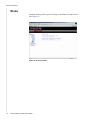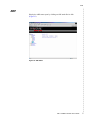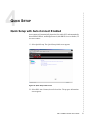
1
6211-I2 ADSL2+ Router User’s Guide
May 2006
Document Part Number: 6211-A2-ZB21-60
Zhone Technologies
@Zhone Way
7001 Oakport Street
Oakland, CA 94621
USA
510.777.7000
www.zhone.com
[email protected]
COPYRIGHT 2000–2006 Zhone Technologies, Inc. All rights reserved.
This publication is protected by copyright law. No part of this publication may
be copied, distributed, displayed, modified, transmitted, stored in a retrieval
system, or translated without express written permission from Zhone
Technologies, Inc.
Acculink, ADSL/R, Bitstorm, Comsphere, DSL the Easy Way, ETC,
Etherloop, FrameSaver, GranDSLAM, GrandVIEW, Hotwire, the Hotwire
logo, iMarc, Jetstream, MVL, NextEDGE, Net to Net Technologies,
OpenLane, Paradyne, the Paradyne logo, Performance Wizard, ReachDSL,
StormPort, and TruePut are registered trademarks of Zhone Technologies, Inc.
BAN, Connect to Success, GigMux, Hotwire Connected, JetFusion,
JetVision, MALC, MicroBurst, PacketSurfer, Quick Channel, Raptor, Reverse
Gateway, SLMS, Spectrum Manager, StormTracker, Z-Edge, Zhone, ZMS,
and the Zhone logo are trademarks of Zhone Technologies, Inc.
All other products names or service marks mentioned herein are the
trademarks, trade names and service names of their respective owners.
Zhone Technologies makes no representation or warranties with respect to the
contents hereof and specifically disclaims any implied warranties of
merchantability, noninfringement, or fitness for a particular purpose. Further,
Zhone Technologies reserves the right to revise this publication and to make
changes from time to time in the contents hereof without obligation of Zhone
Technologies to notify any person of such revision or changes.
! Important Safety Instructions
1 Read and follow all warning notices and instructions marked on the
product or included in the manual.
2 Slots and openings in the cabinet are provided for ventilation. To ensure
reliable operation of the product and to protect it from overheating, these
slots and openings must not be blocked or covered.
3 Do not allow anything to rest on the power cord and do not locate the
product where persons will walk on the power cord.
4 Do not attempt to service this product yourself, as opening or removing
covers may expose you to dangerous high voltage points or other risks.
Refer all servicing to qualified service personnel.
5 General purpose cables are used with this product for connection to the
network. Special cables, which may be required by the regulatory
inspection authority for the installation site, are the responsibility of the
customer. Use a UL Listed, CSA certified, minimum No. 24 AWG line
cord for connection to the Digital Subscriber Line (DSL) network.
6 When installed in the final configuration, the product must comply with
the applicable Safety Standards and regulatory requirements of the
country in which it is installed. If necessary, consult with the appropriate
regulatory agencies and inspection authorities to ensure compliance.
7 A rare phenomenon can create a voltage potential between the earth
grounds of two or more buildings. If products installed in separate
buildings are interconnected, the voltage potential may cause a hazardous
condition. Consult a qualified electrical consultant to determine whether
or not this phenomenon exists and, if necessary, implement corrective
action prior to interconnecting the products.
8 Input power to this product must be provided by one of the following: (1)
a UL Listed/CSA certified power source with a Class 2 or Limited Power
Source (LPS) output for use in North America, or (2) a certified
transformer, with a Safety Extra Low Voltage (SELV) output having a
maximum of 240 VA available, for use in the country of installation.
9 In addition, since the equipment is to be used with telecommunications
circuits, take the following precautions:
— Never install telephone wiring during a lightning storm.
— Never install telephone jacks in wet locations unless the jack is
specifically designed for wet locations.
— Never touch uninsulated telephone wires or terminals unless the
telephone line has been disconnected at the network interface.
— Use caution when installing or modifying telephone lines.
— Avoid using a telephone (other than a cordless type) during an
electrical storm. There may be a remote risk of electric shock from
lightning.
— Do not use the telephone to report a gas leak in the vicinity of the
leak.
6211-I2 ADSL2+ Router User’s Guide
3
CE Marking
When the product is marked with the CE mark on the equipment label, a
supporting Declaration of Conformity may be downloaded from the Zhone
World Wide Web site at www.zhone.com.
FCC Part 15 Declaration
An FCC Declaration of Conformity may be downloaded from the Zhone
World Wide Web site at www.zhone.com.
This device complies with Part 15 of the FCC Rules. Operation is subject to
the following two conditions: (1) this device may not cause harmful
interference, and (2) this device must accept any interference received,
including interference that may cause undesired operation.
The authority to operate this equipment is conditioned by the requirement that
no modifications will be made to the equipment unless the changes or
modifications are expressly approved by the responsible party.
This equipment has been tested and found to comply with the limits for a
Class B digital device, pursuant to Part 15 of the FCC Rules. These limits are
designed to provide reasonable protection against harmful interference in a
residential installation. This equipment generates, uses, and can radiate radio
frequency energy and, if not installed and used in accordance with the
instructions, may cause harmful interference to radio communications.
However, there is no guarantee that interference will not occur in a particular
installation. If this equipment does cause harmful interference to radio or
television reception, which can be determined by turning the equipment off
and on, the user is encouraged to try to correct the interference by one or more
of the following measures:
l
Reorient or relocate the receiving antenna.
l
Increase the separation between the equipment and receiver.
l
Connect the equipment into an outlet on a circuit different from that to
which the receiver is connected.
l
Consult the dealer or an experienced radio/TV technician for help.
Notice to Users of the United States Telephone Network
The following notice applies to versions of the modem that have been FCC
Part 68 approved.
This equipment complies with Part 68 of the FCC rules and the requirements
adopted by the Administrative Council for Terminal Attachment (ACTA). On
the bottom side of this equipment is a label that contains, among other
information, a product identifier in the format US:AAAEQ##TXXXX. If
requested, this number must be provided to the Telephone Company.
4
6211-I2 ADSL2+ Router User’s Guide
This equipment is intended to connect to the Public Switched Telephone
Network through a Universal Service Order Code (USOC) type RJ11C jack.
A plug and jack used to connect this equipment to the premises wiring and
telephone network must comply with the applicable FCC Part 68 rules and
requirements adopted by the ACTA. A compliant telephone cord and modular
plug is provided with this product. It has been designed to be connected to a
compatible modular jack that is also compliant.
The Ringer Equivalence Number (REN) is used to determine the number of
devices that may be connected to a telephone line. Excessive RENs on a
telephone line may result in the devices not ringing in response to an
incoming call. In most but not all areas, the sum of RENs should not exceed
five (5.0). To be certain of the number of devices that may be connected to a
line, as determined by the total RENs, contact the local Telephone Company.
The REN for this product is part of the product identifier that has the format
US:AAAEQ##TXXXX. The digits represented by ## are the REN without a
decimal point. For example, 03 represents a REN of 0.3.
If the modem causes harm to the telephone network, the Telephone Company
will notify you in advance that temporary discontinuance of service may be
required. But if advance notice is not practical, the Telephone Company will
notify the customer as soon as possible. Also, you will be advised of your
right to file a complaint with the FCC if you believe it is necessary.
The Telephone Company may make changes in its facilities, equipment,
operations or procedures that could affect the operation of the equipment. If
this happens, the Telephone Company will provide advance notice in order for
you to make necessary modifications to maintain uninterrupted service. If
trouble is experienced with the modem, refer to the repair and warranty
information in this document.
If the equipment is causing harm to the telephone network, the Telephone
Company may request that you disconnect the equipment until the problem is
resolved.
The user may make no repairs to the equipment.
Connection to party line service is subject to state tariffs. Contact the state
public utility commission, public service commission or corporation
commission for information.
If the site has specially wired alarm equipment connected to the telephone
line, ensure the installation of the modem does not disable the alarm
equipment. If you have questions about what will disable alarm equipment,
consult your Telephone Company or a qualified installer.
6211-I2 ADSL2+ Router User’s Guide
5
Notice to Users of the Canadian Telephone Network
NOTICE: This equipment meets the applicable Industry Canada Terminal
Equipment Technical Specifications. This is confirmed by the registration
number. The abbreviation IC before the registration number signifies that
registration was performed based on a Declaration of Conformity indicating
that Industry Canada technical specifications were met. It does not imply that
Industry Canada approved the equipment.
NOTICE: The Ringer Equivalence Number (REN) for this terminal
equipment is labeled on the equipment. The REN assigned to each terminal
equipment provides an indication of the maximum number of terminals
allowed to be connected to a telephone interface. The termination on an
interface may consist of any combination of devices subject only to the
requirement that the sum of the Ringer Equivalence Numbers of all the
devices does not exceed five.
If your equipment is in need of repair, contact your local sales representative,
service representative, or distributor directly.
! CANADA - EMI NOTICE:
This Class B digital apparatus meets all requirements of the Canadian
interference-causing equipment regulations.
Cet appareil numérique de la classe B respecte toutes les exigences du
règlement sur le matérial brouilleur du Canada.
Japan Notices
This is a Class B product based on the standard of the Voluntary Control
Council for Interference from Information Technology Equipment
(VCCI). If this is used near a radio or television receiver in a domestic
environment, it may cause radio interference. Install and use the
equipment according to the instruction manual.
6
6211-I2 ADSL2+ Router User’s Guide
CONTENTS
About This Guide 11
Document Purpose and Intended Audience ............................................................11
Document Summary ...................................................................................................11
Product-Related Documents ......................................................................................12
Contacting Global Service and Support ..................................................................12
Technical Support .......................................................................................................12
Service Requirements.................................................................................................12
Chapter 1
Introduction ............................................................................................................13
Introduction .................................................................................................................13
Features ........................................................................................................................13
System Requirements .................................................................................................13
Parts List ......................................................................................................................14
Front Panel ...................................................................................................................15
Rear Panel ....................................................................................................................16
Chapter 2
Hardware Installation and PC Setup ............................................................17
Overview ......................................................................................................................17
Connecting the Hardware ..........................................................................................17
Installing the USB Driver ..........................................................................................19
Configuring Your Computer .....................................................................................22
Windows XP PCs....................................................................................................22
Windows 2000 PCs.................................................................................................24
Windows ME PCs...................................................................................................24
Windows 95 and Windows 98 PCs.........................................................................25
Windows NT 4.0.....................................................................................................26
Logging in to Your Router ........................................................................................27
Chapter 3
Device Information ...............................................................................................29
Status Summary ..........................................................................................................29
WAN .............................................................................................................................30
LAN Statistics .............................................................................................................31
WAN Statistics ............................................................................................................32
6211-I3 ADSL2+ Router User’s Guide
7
ATM Statistics.............................................................................................................33
ADSL Statistics ...........................................................................................................34
ADSL BER Test .........................................................................................................34
Route .............................................................................................................................36
ARP...............................................................................................................................37
Chapter 4
Quick Setup ............................................................................................................39
Quick Setup with Auto-Connect Enabled ...............................................................39
Quick Setup with Auto-Connect Disabled ..............................................................41
Chapter 5
Advanced Setup ....................................................................................................43
WAN .............................................................................................................................43
Add Function – ATM PVC Configuration .............................................................44
Connection Type Screen .........................................................................................45
Bridge Service and Quality of Service Screen........................................................46
WAN Setup - Summary ..........................................................................................47
Remove Function ....................................................................................................48
Finish Function .......................................................................................................48
Local Area Network (LAN) Setup ...........................................................................49
NAT ..............................................................................................................................50
Virtual Servers ........................................................................................................50
Port Triggering ............................................................................................................52
DMZ Host ....................................................................................................................54
Firewall.........................................................................................................................55
IP Filtering – Outgoing ...........................................................................................55
IP Filtering – Incoming...........................................................................................57
Firewall – MAC Filtering .......................................................................................59
Parental Control ......................................................................................................62
Quality of Service .......................................................................................................64
Routing – Default Gateway .......................................................................................66
Routing – Static Route ...............................................................................................67
Routing – RIP ..............................................................................................................69
DNS Server ..................................................................................................................70
Dynamic DNS .............................................................................................................71
ADSL ............................................................................................................................73
Modulation Methods...............................................................................................73
Capability................................................................................................................73
DSL Advanced Settings .............................................................................................74
Tone Selection .............................................................................................................75
Port Mapping ...............................................................................................................76
Certificate .....................................................................................................................77
Chapter 6
Diagnostics .............................................................................................................81
Testing the DSL Connection .....................................................................................81
8
6211-AZ-ZB21-40
Chapter 7
Management ...........................................................................................................83
Saving and Restoring the Configuration .................................................................83
Backing Up Configuration Settings .........................................................................83
Restoring Configuration Settings .............................................................................85
Restoring Default Settings .........................................................................................87
System Log ..................................................................................................................89
View System Log....................................................................................................90
Configure System Log ............................................................................................91
TR-069 Client ..............................................................................................................92
Internet Time ...............................................................................................................93
Access Control – Services .........................................................................................94
Access Control – IP Addresses .................................................................................96
Access Control – Passwords .....................................................................................98
Update Software..........................................................................................................98
Reboot Router .............................................................................................................99
Appendix A Specifications ......................................................................................................101
Index ....................................................................................................................................................103
6211-I3 ADSL2+ Router User’s Guide
9
10
6211-AZ-ZB21-40
ABOUT THIS GUIDE
Document Purpose and Intended Audience
This guide contains detailed information about the 6211-I2 router. It is
intended for all users of the router.
Document Summary
Section
Description
Chapter 1, Introduction
Describes the features of the router.
Chapter 2, Hardware
Installation and PC Setup
Shows how to connect the router and set up
your PC to manage the router.
Chapter 3, Device
Information
Explains how to use the web interface to obtain
statistics and other information about the
router.
Chapter 4, Quick Setup
Describes the Quick Setup configuration
process.
Chapter 5, Advanced Setup Describes configuration of the advanced router
features.
Chapter 6, Diagnostics
Describes the test screen.
Chapter 7, Management
Describes the management functions of the
router, including backing up and restoring
configuration settings, viewing the system log,
configuraing access control, and upgrading
software.
Appendix A,
Specifications
Lists the specifications of the router.
Index
Lists key terms, concepts, and sections in
alphabetical order.
6211-I2 ADSL2+ Router User’s Guide
11
Product-Related Documents
Complete documentation for Zhone products is available online at
www.zhone.com.
Contacting Global Service and Support
Contact Global Service and Support (GSS) if you have any questions about
this or other Zhone products. Before contacting GSS, make sure you have the
following information:
z
Zhone product you are using
z
System configuration
z
Software version running on the system
z
Description of the issue
Technical Support
If you require assistance with the installation or operation of your product, or
if you want to return a product for repair under warranty, contact GSS. The
contact information is as follows:
E-mail
[email protected]
Telephone (North America)
877-ZHONE20
Telephone (International)
510-777-7133
Internet
www.zhone.com/support
If you purchased the product from an authorized dealer, distributor, Value
Added Reseller (VAR), or third party, contact that supplier for technical
assistance and warranty support.
Service Requirements
If the product malfunctions, all repairs must be performed by the
manufacturer or a Zhone-authorized agent. It is the responsibility of users
requiring service to report the need for service to GSS.
12
6211-I2 ADSL2+ Router User’s Guide
1
INTRODUCTION
Introduction
Congratulations on becoming the owner of a 6211 ADSL router.
This User’s Guide will show you how to set up the router, and how to
customize its configuration to get the most out of this product.
Features
The 6211 router has the following features:
z
z
z
z
z
Built-in ADSL modem which offers G.Dmt, G.lite, T1.413, ADSL2,
Annex L, and ADSL2+ to meet different linking speeds from your ISP.
10/100BaseT Ethernet port to provide Internet connectivity to all
computers on your LAN via additional Ethernet Switch/HUB.
USB port allows quick installation.
Built-in splitter provides you to connect telephone directly without using
extra splitter (Model 6211-I1-x0x).
Configuration program accessible via a web browser, such as Microsoft
Internet Explorer.
System Requirements
In order to use the 6211 ADSL router for Internet access, you must have the
following:
z
ADSL service subscription from your ISP
z
A PC with:
— An Ethernet 10/100BaseT network interface card or USB port
— A processor equivalent to or faster than a Pentium II 133 MHz
— 32 MB RAM or greater
— If USB drivers will be installed, 5 MB free disk space
— Windows 95b, 98, 98SE, 2000, ME, NT, or XP (Note: Windows 95
requires the installation of the Winsock program, not included.
Windows 95 and 98 do not support USB.)
6211-I2 ADSL2+ Router User’s Guide
13
Introduction
— (Optional) An Ethernet hub or switch, if you wish to connect the
router to several computers on an Ethernet network.
— For system configuration using the supplied web-based program: a
web browser such as Internet Explorer Version 6.0 or later. Netscape
is not supported.
Parts List
In addition to this document, your 6211 ADSL router should come with the
following:
z
6211 ADSL router
z
Power adapter
z
Ethernet cable (RJ45, straight-through type)
z
Phone cable (RJ11)
z
USB cable
B
US
N
LA
ITY
TIV
AC
US
AT
ST
R
WE
PO
04-17511
Figure 1: 6211 ADSL Router Package Contents
14
6211-I2 ADSL2+ Router User’s Guide
Front Panel
Front Panel
The front panel contains LED indicators that show the status of the unit.
B
US
N
LA
ITY
TIV
AC
US
AT
ST
R
WE
PO
05-17610
Figure 2: Front Panel LEDs
Table 1:
Front Panel Label and LEDs
Label
Color
Function
POWER
Green
On: Unit is powered on
Off: Unit is powered off
STATUS
Green
On: ADSL link is established and
active
Flashing: Trying to create an
ADSL connection
Off: No ADSL link
ACTIVITY
Green
Flashing: ADSL data transfer
LAN
Green
On: LAN link is established
Flashing: Data transfer at LAN
connection
Off: No LAN link
USB
Green
On: USB link is established
Off: No USB link
6211-I2 ADSL2+ Router User’s Guide
15
Introduction
Rear Panel
The rear panel contains the ports for the router's data and power connections.
Table 2:
16
Rear Panel Labels and Connectors
Label
Function
LINE
Connects to your ADSL line
PHONE (Model
6211-I1-x0x)
Connects to your telephone
USB
USB outlet, for PC USB port connection
LAN
Connects the CPE to your PC's Ethernet port, or
to the uplink port on your LAN's hub or switch,
using the cable provided
RESET/DEFAULT
To reset the router to its default settings
POWER
Connects to the supplied power adapter
6211-I2 ADSL2+ Router User’s Guide
2
HARDWARE INSTALLATION AND PC SETUP
Overview
This chapter provides basic instructions for connecting the router to a
computer or a LAN and to the Internet using DSL. The first part provides
instructions to set up the hardware, and the second part describes how to
prepare your PC for use with the router.
It is assumed that you have already subscribed to DSL service with your
Internet service provider (ISP).
Connecting the Hardware
Caution
Shut down your PC and any other equipment before connecting it to
the router.
To connect your router:
1 Connect your ADSL line to the port labeled LINE on the rear panel of the
device.
2 For routers with a phone port (model numbers of the form 6211-I1-x0x),
optionally connect your telephone to the port labeled PHONE.
3 Connect your PC or a LAN:
— Use the supplied Ethernet cable to connect your PC directly to the
router. Connect one end of the Ethernet cable to the port labeled LAN
on the router and connect the other end to the Ethernet port of your
computer.
— Alternatively, use the supplied USB cable to connect your PC directly
to the router. Connect one end of the USB cable to the port labeled
USB on the router and connect the other end to a free USB port on
your PC. Install the USB drivers as described in the user’s guide on
the CD.
— If your LAN has more than one computer, you can attach one end of
an Ethernet cable to a hub or a switch and the other to the LAN port
of the router. Either a crossover or straight-through Ethernet cable can
be used.
6211-I2 ADSL2+ Router User’s Guide
17
Hardware Installation and PC Setup
4. Connect the AC power adapter to the POWER connector on the back of
the device and plug the adapter into a wall outlet or power strip.
RESET
LINE
PHONE
USB
LAN
DEFAULT
1
2
3
POWER
4
OR
04-17510
Figure 3: Hardware Installation
5. Turn on and boot up your PC and any LAN devices, such as hub or
switches, and any computers connected to them.
6. Verify that the router's LEDs are illuminated as shown in Table 3.
Table 3:
18
LED Indicators (Sheet 1 of 2)
This LED . . .
Should be:
POWER
Solid green to indicate that the device is turned on. If this
light is not on, check if the power adapter is attached to the
router and plugged into an AC power source.
STATUS
Solid green to indicate that the router can communicate
with your ISP via ADSL, or flashing when the router is
trying to connect to your ISP.
ACTIVITY
Flashing when the device is sending or receiving data over
the ADSL connection.
6211-I2 ADSL2+ Router User’s Guide
Installing the USB Driver
Table 3:
LED Indicators (Sheet 2 of 2)
This LED . . .
Should be:
LAN
Solid green to indicate that the device can communicate
with your PC via Ethernet, or flashing when the router is
sending or receiving data over Ethernet.
USB
Solid green when connected, flashing when the router is
sending or receiving data.
If the LEDs are illuminated as expected, the router is working properly.
Installing the USB Driver
The following section applies only if you use the USB connector on the
router. If you connect the USB cable between your PC and the router,
Windows detects the new hardware and the Found New Hardware Wizard
appears on your PC monitor. Follow this procedure:
1 Choose "Install from a list or specific location" from the Wizard's menu,
then click on Next.
Figure 4: Found New Hardware Wizard
6211-I2 ADSL2+ Router User’s Guide
19
Hardware Installation and PC Setup
2 Insert the supplied CD ROM and use Browse to include the CD drive in
the search.
Figure 5: Search and Installation Options
3 If the Wizard reports a compatibility issue, select "Continue Anyway".
Installation of the USB driver proceeds.
Figure 6: Compatibility Warning
20
6211-I2 ADSL2+ Router User’s Guide
Installing the USB Driver
Figure 7: Progress Screen
4. When prompted, click on Finish to close the Wizard.
Figure 8: Completion Screen
6211-I2 ADSL2+ Router User’s Guide
21
Hardware Installation and PC Setup
Configuring Your Computer
Before you can access the router over the LAN or the USB port, you have to
configure your PC's TCP/IP address to be 192.168.1.x (where x is any number
between 3 and 254), with a subnet mask of 255.255.255.0. Your router's
default IP address is 192.168.1.1.
Windows XP PCs
1 In the Windows task bar, click on the Start button, and then click on
Control Panel.
2 Double-click on the Network Connections icon.
3 In the LAN or High-Speed Internet window, right-click on the icon
corresponding to your network interface card (NIC) or USB connection,
and select Properties. (Often this icon is labeled Local Area Connection).
The Local Area Connection dialog box displays with a list of currently
installed network items.
4 Ensure that the check box to the left of the item labeled Internet Protocol
(TCP/IP) is checked, and click on Properties.
Figure 9: Network Connections (Windows XP)
22
6211-I2 ADSL2+ Router User’s Guide
Configuring Your Computer
Figure 10: Local Area Connection Properties (Windows XP)
5 In the Internet Protocol (TCP/IP) Properties dialog box, click on the radio
button labeled Use the following IP address. Type an address between
192.168.1.3 and 192.168.1.254 in the IP Address field (192.168.1.20 is
shown here as an example) and 255.255.255.0 in the Subnet Mask field.
Figure 11: TCP/IP Properties (Windows XP)
6211-I2 ADSL2+ Router User’s Guide
23
Hardware Installation and PC Setup
6. Click on OK twice to confirm your changes, and close the Control Panel.
Windows 2000 PCs
1 In the Windows task bar, click on the Start button, point to Settings, and
then click on Control Panel.
2 Double-click on the Network and Dial-up Connections icon.
3 In the Network and Dial-up Connections window, right-click on the Local
Area Connection icon, and then select Properties.
The Local Area Connection Properties dialog box display a list of
currently installed network components. If the list includes Internet
Protocol (TCP/IP), the protocol has already been enabled; skip to Step 10.
4 If Internet Protocol (TCP/IP) does not appear as an installed component,
click on Install.
5 In the Select Network Component Type dialog box, select Protocol, and
then click on Add.
6 Select Internet Protocol (TCP/IP) in the Network Protocols list, and then
click on OK.
You may be prompted to install files from your Windows 2000
installation CD or other medium. Follow the instructions to install the
files.
7 If prompted, click on OK to restart your computer with the new settings.
8 After restarting your PC, double-click on the Network and Dial-up
Connections icon in the Control Panel.
9 In Network and Dial-up Connections window, right-click on the Local
Area Connection icon, and then select Properties.
10 In the Local Area Connection Properties dialog box, select Internet
Protocol (TCP/IP), and then click on Properties.
11 In the Internet Protocol (TCP/IP) Properties dialog box, click on the radio
button labeled Use the following IP address. Type an address between
192.168.1.3 and 192.168.1.254 in the IP Address field and 255.255.255.0
in the Subnet Mask field.
12 Click on OK twice to confirm and save your changes, and then close the
Control Panel.
Windows ME PCs
1 In the Windows task bar, click on the Start button, point to Settings, and
then click on Control Panel.
2 Double-click on the Network and Dial-up Connections icon.
3 In the Network and Dial-up Connections window, right-click on the
Network icon, and then select Properties.
24
6211-I2 ADSL2+ Router User’s Guide
Configuring Your Computer
The Network Properties dialog box displays a list of currently installed
network components. If the list includes Internet Protocol (TCP/IP), the
protocol has already been enabled; skip to Step 11.
4 If Internet Protocol (TCP/IP) does not appear as an installed component,
click on Add.
5 In the Select Network Component Type dialog box, select Protocol, and
then click on Add.
6 Select Microsoft in the Manufacturers box.
7 Select Internet Protocol (TCP/IP) in the Network Protocols list, and then
click on OK.
You may be prompted to install files from your Windows Me installation
CD or other media. Follow the instructions to install the files.
8 If prompted, click on OK to restart your computer with the new settings.
9 After restarting your PC, double-click on the Network and Dial-up
Connections icon in the Control Panel.
10 In Network and Dial-up Connections window, right-click on the Network
icon, and then select Properties.
11 In the Network Properties dialog box, select TCP/IP, and then click on
Properties.
12 In the TCP/IP Settings dialog box, click on the radio button labeled Use
the following IP address. Type an address between 192.168.1.3 and
192.168.1.254 in the IP Address field and 255.255.255.0 in the Subnet
Mask field.
13 Click on OK twice to confirm and save your changes, and then close the
Control Panel.
Windows 95 and Windows 98 PCs
1 In the Windows task bar, click on the Start button, point to Settings, and
then click on Control Panel.
2 Double-click on the Network icon.
The Network dialog box displays a list of currently installed network
components. If the list includes TCP/IP, the protocol has already been
enabled. Skip to step 9.
3 If TCP/IP does not appear as an installed component, click on Add. The
Select Network Component Type dialog box appears.
4 Select Protocol, and then click on Add.
The Select Network Protocol dialog box appears.
5 Click on Microsoft in the Manufacturers list box, and then click on TCP/
IP in the Network Protocols list box.
6 Click on OK to return to the Network dialog box, and then click on OK
again.
6211-I2 ADSL2+ Router User’s Guide
25
Hardware Installation and PC Setup
You may be prompted to install files from your Windows 95/98
installation CD. Follow the instructions to install the files.
7 Click on OK to restart the PC and complete the TCP/IP installation.
8 After restarting your PC, open the Control Panel window, and then click
on the Network icon.
9 Select the network component labeled TCP/IP, and then click on
Properties.
If you have multiple TCP/IP listings, select the listing associated with
your network card or adapter.
10 In the TCP/IP Properties dialog box, click on the IP Address tab.
11 Click in the radio button labeled Use the following IP address. Type an
address between 192.168.1.3 and 192.168.1.254 in the IP Address field
and 255.255.255.0 in the Subnet Mask field.
12 Click on OK twice to confirm and save your changes. You will be
prompted to restart Windows. Click on Yes.
Windows NT 4.0
1 In the Windows NT task bar, click on the Start button, point to Settings,
and then click on Control Panel.
2 In the Control Panel window, double click on the Network icon.
3 In the Network dialog box, click on the Protocols tab.
The Protocols tab displays a list of currently installed network protocols.
If the list includes TCP/IP, the protocol has already been enabled. Skip to
Step 9.
4 If TCP/IP does not appear as an installed component, click on Add.
5 In the Select Network Protocol dialog box, select TCP/IP, and then click
on OK.
You may be prompted to install files from your Windows NT installation
CD or other medium. Follow the instructions to install the files.
After all files are installed, a window appears to inform you that a TCP/IP
service called DHCP can be set up to dynamically assign IP information.
6 Click on Yes to continue, and then click on OK, if prompted, to restart
your computer.
7 After restarting your PC, open the Control Panel window, and then
double-click on the Network icon.
8 In the Network dialog box, click on the Protocols tab.
9 In the Protocols tab, select TCP/IP, and then click on Properties.
10 In the Microsoft TCP/IP Properties dialog box, click on the radio button
labeled Use the following IP address. Type an address between
26
6211-I2 ADSL2+ Router User’s Guide
Logging in to Your Router
192.168.1.3 and 192.168.1.254 in the IP Address field and 255.255.255.0
in the Subnet Mask field.
11 Click on OK twice to confirm and save your changes, and then close the
Control Panel.
Logging in to Your Router
This section shows how to connect to the router's web interface, configure
settings, and observe some statistics of your Internet connection.
1 Open your Web browser, and type the following URL in the address/
location box, and press Enter:
http://192.168.1.1
This is the default IP address for the LAN port on the router.
A login screen appears.
Figure 12: Login Screen
If you have problem connecting to the router, verify that your PC is
properly configured within the subnet of the router's default IP address
192.168.1.1. Setup is described in Configuring Your Computer on
page 22.
6211-I2 ADSL2+ Router User’s Guide
27
Hardware Installation and PC Setup
2 Enter your user name and password, and then click on OK to display the
home page of the router's web interface. There are two default user name
and password combinations:
Table 4:
Default User Names and Passwords
User Name
Password
Capability
user
user
Can display device status, but cannot
change or save configuration options.
admin
admin
Can perform all functions.
You can change the passwords at any time.
The home page is shown in Figure 13.
Figure 13: Web Interface Home Page
28
6211-I2 ADSL2+ Router User’s Guide
3
DEVICE INFORMATION
Status Summary
Display the general status report for the router by clicking on Summary under
Device Info (Figure 14).
Figure 14: Status Summary
6211-I2 ADSL2+ Router User’s Guide
29
Device Information
WAN
Display the WAN status report from the by clicking on WAN under Device
Info (Figure 15).
Figure 15: WAN Status
30
6211-I2 ADSL2+ Router User’s Guide
LAN Statistics
LAN Statistics
Display LAN statistics by clicking on LAN under Statistics (Figure 16).
Figure 16: LAN Statistics
6211-I2 ADSL2+ Router User’s Guide
31
Device Information
WAN Statistics
Display WAN statistics by clicking on WAN under Statistics (Figure 17).
Figure 17: WAN Statistics
32
6211-I2 ADSL2+ Router User’s Guide
ATM Statistics
ATM Statistics
Display ATM statistics by clicking on ATM under Statistics (Figure 18).
Figure 18: ATM Statistics
6211-I2 ADSL2+ Router User’s Guide
33
Device Information
ADSL Statistics
Display ADSL statistics by clicking on ADSL under Statistics (Figure 19).
Figure 19: ADSL Status
ADSL BER Test
The ADSL Bit Error Rate (BER) test determines the quality of the ADSL
connection. The test is performed by transferring idle cells containing a
known pattern and comparing the received data with this known pattern to
check for any errors (Figure 20 and Figure 21).
To run a BER test:
1 Click on the ADSL BER Test button.
2 Select the test duration and click on Start
3 Check the result.
34
6211-I2 ADSL2+ Router User’s Guide
ADSL BER Test
Figure 20: ADSL BER Test — Start
Figure 21: ADSL BER Test — Result
6211-I2 ADSL2+ Router User’s Guide
35
Device Information
Route
Obtain the Routing status report by clicking on the Route item under Device
Info (Figure 22)
Figure 22: Route Information
36
6211-I2 ADSL2+ Router User’s Guide
ARP
ARP
Display the ARP status report by clicking on ARP under Device Info
(Figure 23)
Figure 23: ARP Status
6211-I2 ADSL2+ Router User’s Guide
37
Device Information
38
6211-I2 ADSL2+ Router User’s Guide
4
QUICK SETUP
Quick Setup with Auto-Connect Enabled
Auto-connect will automatically detect the first usable PVC and automatically
detect PPPoE, PPPoA, and Bridge Protocol (with DHCP Server available). To
use auto-connect:
1 Select Quick Setup. The Quick Setup initial screen appears.
Figure 24: Quick Setup Initial Screen
2 Select DSL Auto-Connect, then click on Next. The progress information
screen appears.
6211-I2 ADSL2+ Router User’s Guide
39
Quick Setup
Figure 25: Detecting Available PVC
Figure 26: Detecting available PVC – Available PVC Detected
40
6211-I2 ADSL2+ Router User’s Guide
Quick Setup with Auto-Connect Disabled
Quick Setup with Auto-Connect Disabled
1 Select Quick Setup. The Quick Setup initial screen appears.
Figure 27: Specifying VPI and VCI
2 Verify that DSL Auto-Connect is not selected. Specify VPI and VCI as
directed by your ISP. Click on Next.
3 Use Advanced Setup to configure the PVC.
6211-I2 ADSL2+ Router User’s Guide
41
Quick Setup
42
6211-I2 ADSL2+ Router User’s Guide
5
ADVANCED SETUP
WAN
Set up WAN parameters as directed by your ISP.
Figure 28: WAN Setup Screen
6211-A2-ZB21-60
6211-I2 ADSL2+ Router User’s Guide
43
Advanced Setup
Add Function – ATM PVC Configuration
If you want to add a new rule for the WAN interface, click on the Add button.
The ATM PVC Configuration screen appears. The ATM PVC Configuration
screen allows you to configure an ATM PVC identifier (VPI and VCI) and
select a service category.
Figure 29: ATM PVC Configuration Screen
Verify the following values with your ISP before you change them.
z
VPI (Virtual Path Identifier) – The valid range is 0 to 255.
z
VCI (Virtual Channel Identifier) – The valid range is 32 to 65535.
z
Service Category – Five classes of traffic defined are defined:
— UBR Without PCR
— UBR With PCR
— CBR
— Non-Realtime VBR
— Realtime VBR
44
6211-I2 ADSL2+ Router User’s Guide
6211-A2-ZB21-60
WAN
Connection Type Screen
Select the type of network protocol and encapsulation mode over the ATM
PVC that your ISP has instructed you to use, then click on Next button.
Figure 30: Connection Type Screen
Select a connection type and click on Next.
6211-A2-ZB21-60
6211-I2 ADSL2+ Router User’s Guide
45
Advanced Setup
Bridge Service and Quality of Service Screen
This WAN service can be enabled or disabled by clicking in the check box.
Enabling QoS for a PVC improves performance for selected classes of
applications. However, since QoS also consumes system resources, the
number of PVCs is reduced. The default setting for QoS is disabled. If you
want to enable QoS service, select the "Enable Quality Of Service" check box.
After finishing steps as above, click on the Next button.
Figure 31: Enable Bridge Service
46
6211-I2 ADSL2+ Router User’s Guide
6211-A2-ZB21-60
WAN
WAN Setup - Summary
Make sure that the settings on the WAN Setup screen match the settings
provided by your ISP. If all settings are correct, click on the Save button to
save these settings; if not, click on the Back button to make any
modifications. If you want to change any item after saving, click on the Edit
button to make any modifications.
Figure 32: WAN Setup Summary
Note
Activate this WAN interface by clicking on the Finish button and further
configuring services over this interface. The router supports up to five
WAN connections.
6211-A2-ZB21-60
6211-I2 ADSL2+ Router User’s Guide
47
Advanced Setup
Remove Function
If you want to delete a connection from the listed WAN setup, click in the
Remove check box next to the item, then click on the Remove button.
Figure 33: WAN Setup List
Finish Function
After you change any item in WAN Setup, remember to click on the Finish
button to apply the changes and reboot the system.
48
6211-I2 ADSL2+ Router User’s Guide
6211-A2-ZB21-60
Local Area Network (LAN) Setup
Local Area Network (LAN) Setup
You can configure the DSL Router IP address and Subnet Mask for the LAN
interface to conform your LAN's IP Subnet. The Save button only saves the
LAN configuration data. The Save/Reboot button saves the LAN
configuration data and reboots the router to make the new configuration
effective.
Figure 34: LAN Setup
6211-A2-ZB21-60
6211-I2 ADSL2+ Router User’s Guide
49
Advanced Setup
NAT
You can configure the Virtual Server, Port Triggering, and DMZ Host when
NAT is enabled.
Virtual Servers
A virtual server allows you to direct incoming traffic from the WAN side to a
specific IP address on the LAN side. Click on the Add button to add a virtual
server.
Figure 35: NAT Virtual Server Setup
50
6211-I2 ADSL2+ Router User’s Guide
6211-A2-ZB21-60
NAT
You can select a Service or make new one. Enter the Server IP Address, then
click on Save/Apply to submit your configuration.
Figure 36: Virtual Server Add Screen
On this screen you can view and delete servers. Click in the check box under
Remove and click on the Remove button to delete selected virtual servers.
Figure 37: Removing Selected Virtual Servers
6211-A2-ZB21-60
6211-I2 ADSL2+ Router User’s Guide
51
Advanced Setup
Port Triggering
Click the on the Add button to add Port Triggering for your Internet
application.
Figure 38: Port Triggering Setup Page
52
6211-I2 ADSL2+ Router User’s Guide
6211-A2-ZB21-60
Port Triggering
You can select an application every time or create new one for your
application. Then click on Save/Apply to save your settings.
Figure 39: Port Triggering Add Page
On this screen you can view and delete applications. Click in the check box
under Remove and click on the Remove button to delete selected applications.
Figure 40: Port Triggering List
6211-A2-ZB21-60
6211-I2 ADSL2+ Router User’s Guide
53
Advanced Setup
DMZ Host
You can define the IP address of the DMZ Host on this screen. Enter the IP
address and click on Save/Apply.
Figure 41: DMZ Host Setup
54
6211-I2 ADSL2+ Router User’s Guide
6211-A2-ZB21-60
Firewall
Firewall
For security reasons, firewall options can be configured only from the LAN
side of the router.
IP Filtering – Outgoing
The outgoing filter will block the traffic from the LAN side to the WAN side.
Click on Add to create filters.
Figure 42: IP Filtering – Outgoing Filter Setup
6211-A2-ZB21-60
6211-I2 ADSL2+ Router User’s Guide
55
Advanced Setup
Input the filter name, source information (from the LAN side), and
Destination information (from the WAN side). Then click on Save/Apply.
Figure 43: IP Filtering - Outgoing Filter Add Page
You can view and delete the outgoing filter settings on this screen.
Figure 44: IP Filtering - Outgoing Filter Setup List
56
6211-I2 ADSL2+ Router User’s Guide
6211-A2-ZB21-60
Firewall
IP Filtering – Incoming
Incoming filter filters the traffic from the WAN side to the LAN side. Click on
Add to add incoming filter settings.
Figure 45: IP Filtering – Incoming Filter Setup Page
6211-A2-ZB21-60
6211-I2 ADSL2+ Router User’s Guide
57
Advanced Setup
Enter a filter name, information about the source address (from the WAN
side), and information about the destination address ( to the LAN side). Select
the protocol and WAN interface. Then click on Save/Apply to add the setting.
Figure 46: IP Filtering - Incoming Filter Add
You can view and delete the incoming filter settings from this screen.
Figure 47: IP Filtering - Incoming Filtering List
58
6211-I2 ADSL2+ Router User’s Guide
6211-A2-ZB21-60
Firewall
Firewall – MAC Filtering
MAC filtering can forward or block traffic by MAC address. You can change
the policy or add settings to the MAC filtering table using the MAC Filtering
Setup screen.
Figure 48: IP Filtering - MAC Filtering Setup
6211-A2-ZB21-60
6211-I2 ADSL2+ Router User’s Guide
59
Advanced Setup
If you click on Change Policy, a confirmation dialog lets you verify your
change.
Figure 49: IP Filtering - MAC Filtering Policy Change Confirmation
60
6211-I2 ADSL2+ Router User’s Guide
6211-A2-ZB21-60
Firewall
If you want to add a setting to the MAC filtering table, enter the Source and
Destination MAC address, and select protocol type, frame direction, and
WAN interface. Then click on Save/Apply to save it.
Figure 50: IP Filtering - MAC Filtering Add Page
On this screen you can view and delete MAC filtering rules.
Figure 51: IP Filtering - MAC Filtering List
6211-A2-ZB21-60
6211-I2 ADSL2+ Router User’s Guide
61
Advanced Setup
Parental Control
Use the Parental Control feature to restrict the days and times a particular
device is allowed to access the Internet.
Figure 52: Parental Control Screen
62
6211-I2 ADSL2+ Router User’s Guide
6211-A2-ZB21-60
Firewall
To set up parental controls:
1 Click on Add. The Time of Day Restriction screen appears.
Figure 53: Parental Control – Time of Day Restrictions
2 Enter a User Name to identify the target of the restrictions.
3 Enter the MAC address of the network adapter to be restricted, and,
optionally, another MAC address.
4 Select the days of the week the restriction is in force.
5 Specify the start and end times the restriction is in force. Use the form
hh:mm, where 23:59, for example, is one minute before midnight.
6 Click on Save/Apply.
6211-A2-ZB21-60
6211-I2 ADSL2+ Router User’s Guide
63
Advanced Setup
Quality of Service
You can configure the Quality of Service to apply different priorities to traffic
on the router.
Figure 54: Quality of Service Setup
64
6211-I2 ADSL2+ Router User’s Guide
6211-A2-ZB21-60
Quality of Service
Click on Add and the Add Network Traffic Class Rule screen appears. Enter
and select QoS parameters, then click on Save/Apply. Note that 802.1p
Priority and TOS are mutually exclusive.
Figure 55: Quality of Service Add Screen
On this screen you can view and delete QoS settings.
Figure 56: Quality of Service List
6211-A2-ZB21-60
6211-I2 ADSL2+ Router User’s Guide
65
Advanced Setup
Routing – Default Gateway
You can change the Default Gateway on the Routing - Default Gateway
screen.
Figure 57: Default Gateway Setup
66
6211-I2 ADSL2+ Router User’s Guide
6211-A2-ZB21-60
Routing – Static Route
Routing – Static Route
Use the Routing - Static Route screen to add a static route to the routing table.
Figure 58: Static Route Setup
6211-A2-ZB21-60
6211-I2 ADSL2+ Router User’s Guide
67
Advanced Setup
Enter the route information and click on Save/Apply to make it active. No
reboot is required.
Figure 59: Static Route Add
68
6211-I2 ADSL2+ Router User’s Guide
6211-A2-ZB21-60
Routing – RIP
Routing – RIP
If RIP is enabled, the router operation can be configured as Active or Passive.
Figure 60: RIP Setup
6211-A2-ZB21-60
6211-I2 ADSL2+ Router User’s Guide
69
Advanced Setup
DNS Server
Use the DNS Server screen to request automatic assignment of a DNS or to
specify a primary and secondary DNS.
Figure 61: DNS Setup
70
6211-I2 ADSL2+ Router User’s Guide
6211-A2-ZB21-60
Dynamic DNS
Dynamic DNS
Use the Dynamic DNS screen to alias a dynamic IP address to a static
hostname, allowing your router to be easily accessed from anywhere on the
Internet.
Figure 62: Dynamic DNS
6211-A2-ZB21-60
6211-I2 ADSL2+ Router User’s Guide
71
Advanced Setup
To set up a Dynamic DNS entry:
1 Click on Add. The Add Dynamic DNS screen appears.
Figure 63: Adding a Dynamic DNS Entry
2 Select a D-DNS Provider from the drop-down list.
3 Enter the Hostname you have selected for the interface.
4 Select the router Interface from the drop-down list.
5 Enter the information you used to register with the dynamic DNS service:
for DynDNS, enter your Username and Password; for TOZ, enter your
E-mail address and Key.
6 Click on Save/Apply.
72
6211-I2 ADSL2+ Router User’s Guide
6211-A2-ZB21-60
ADSL
ADSL
There are three major items in the ADSL settings.
Figure 64: ADSL Settings
Modulation Methods
The following modulation methods are supported by the 6211 ADSL router:
z
G.dmt Enabled
z
G.lite Enabled
z
T1.413 Enabled
z
ADSL2 Enabled
z
Annex L Enabled
z
ADSL2+ Enabled.
Do not change this setting unless so directed by your ISP.
Capability
The following are included under Capability:
6211-A2-ZB21-60
6211-I2 ADSL2+ Router User’s Guide
73
Advanced Setup
z
Bitswap Enable
z
SRA (Seamless Rate Adaptation) Enable
Do not change these settings unless so directed by your ISP.
DSL Advanced Settings
Do not change the DSL Advanced Settings unless so directed by your ISP. To
view the DSL Advanced Settings screen, click on the Advanced Settings
button on the DSL Settings screen (see Figure 64).
There are five test modes between the router and your ISP:
z
z
z
z
z
Normal test: Puts the router in a test mode in which it only sends a
Normal signal.
Reverb test: Puts the router in a test mode in which it only sends a Reverb
signal.
Medley test: Puts the router in a test mode in which it only sends a
Medley signal.
No Retrain: In this mode the router will try to establish a connection as in
normal mode, but once the connection is up it will not retrain if the signal
is lost.
L3: Puts the router into the L3 power state.
Figure 65: DSL Advanced Settings
74
6211-I2 ADSL2+ Router User’s Guide
6211-A2-ZB21-60
Tone Selection
Tone Selection
To view the ADSL Tone Settings screen, click on the Tone Selection button of
the DSL Advanced Settings screen (see Figure 65).
The frequency band of ADSL is split up into 256 separate tones, each spaced
4.3125 kHz apart. With each tone carrying separate data, the technique
operates as if 256 separate modems were running in parallel. The tone range is
from 0 to 31 for upstream and from 32 to 255 for downstream.
Do not change these settings unless so directed by your ISP.
Figure 66: Tone Settings
6211-A2-ZB21-60
6211-I2 ADSL2+ Router User’s Guide
75
Advanced Setup
Port Mapping
Use the Port Mapping screen to map multiple ports to a PVC and create
bridging groups. Each group will perform as an independent network.
Figure 67: Port Mapping
76
6211-I2 ADSL2+ Router User’s Guide
6211-A2-ZB21-60
Certificate
To create a new mapping group:
1 Click on Add. The Port Mapping Configuration screen appears.
Figure 68: Creating a Port Mapping Entry
2 Enter a unique Group name.
3 Select interfaces from the available interface list and add them to the
grouped interface list using the arrow buttons to create the required
mapping of the ports.
4 Click on Save/Apply.
Certificate
Use the Certificate screen to add, view, or remove a certificate for use by a
peer to verify your identity. A maximum of four certificates can be stored.
You can add a certificate either by creating a new one or importing an existing
one from a location where one is stored.
Note
Certificates are used with TR-069. Firmware that does not support
TR-069 will not support certificates.
6211-A2-ZB21-60
6211-I2 ADSL2+ Router User’s Guide
77
Advanced Setup
Figure 69: Certificate
To create a new certificate:
1 Click Create New Certificate Request. Follow the screens that appear to
configure a new certificate.
2 Click on Save/Apply.
78
6211-I2 ADSL2+ Router User’s Guide
6211-A2-ZB21-60
6
DIAGNOSTICS
Testing the DSL Connection
Your router is capable of testing your DSL connection. The individual tests
are listed below. If a test displays a failure status, click on "Test" at the bottom
of this page to make sure the failure status is consistent. If the test result
continues to show a failure, click on "Help" and follow the troubleshooting
procedures.
Figure 71: Diagnostics
6211-I2 ADSL2+ Router User’s Guide
81
Diagnostics
82
6211-I2 ADSL2+ Router User’s Guide
7
MANAGEMENT
Saving and Restoring the Configuration
The configuration of your router can be backed up to a file, and also can be
restored from a file. You can also restore the router to its factory default
configuration.
Backing Up Configuration Settings
To back up your settings, select Management -> Settings -> Backup Settings.
Figure 72: Back Up Settings Screen
6211-I2 ADSL2+ Router User’s Guide
83
Management
Verify that you would like to save the file.
Figure 73: Backup Settings Upload Confirmation
Select the location where you want to save the file.
Figure 74: Backup Settings File Location
84
6211-I2 ADSL2+ Router User’s Guide
Restoring Configuration Settings
Restoring Configuration Settings
To restore saved settings, select Management -> Settings -> Restore User
Settings.
Figure 75: Restore User Settings Screen
Select the backup file you want to restore and click on Update Settings.
Figure 76: Restore Settings File Location
6211-I2 ADSL2+ Router User’s Guide
85
Management
The router will restore settings and reboot to activate the restored settings.
Figure 77: Upload in Progress Screen
86
6211-I2 ADSL2+ Router User’s Guide
Restoring Default Settings
Restoring Default Settings
Restore Default will erase all current settings and restore the router to factory
default settings.
To restore the router to factory default settings, select Management ->
Settings -> Restore Default.
Figure 78: Restore Default Settings Screen
Reply OK to the confirmation dialog.
Figure 79: Restore Default Confirmation Dialog
6211-I2 ADSL2+ Router User’s Guide
87
Management
The router will restore the default settings and reboot.
Figure 80: Restore Default Settings Reboot
88
6211-I2 ADSL2+ Router User’s Guide
System Log
System Log
The System Log dialog allows you to view the System Log and configure the
System Log options.
Figure 81: System Log
6211-I2 ADSL2+ Router User’s Guide
89
Management
View System Log
Click on the "View System Log" button to check the log file.
Figure 82: View System Log
90
6211-I2 ADSL2+ Router User’s Guide
System Log
Configure System Log
If the log is enabled, the system will log selected events: Emergency, Alert,
Critical, Error, Warning, Notice, Informational, and Debugging. All events
above or equal to the selected log level will be logged and displayed.
If the selected mode is "Remote" or "Both", events will be sent to the
specified IP address and UDP port of a remote system log server. If the
selected mode is "Local" or "Both", events will be recorded in the local
memory.
Figure 83: System Log Configuration
Select the desired values and click on the "Save/Apply" button to configure
the system log options.
6211-I2 ADSL2+ Router User’s Guide
91
Management
TR-069 Client
The router includes a TR-069 client which is a WAN management protocol.
Default values are already filled in. If you wish to enable this protocol, then
select Enable and fill in the text boxes according to your configuration. You
must click on the Save/Reboot button for the change to take place. Firmware
versions that support TR-069 do not support SNMP.
92
6211-I2 ADSL2+ Router User’s Guide
Internet Time
Internet Time
Use the Internet Time screen to specify whether the router uses Simple
Network Time Protocol (SNTP) to obtain the time of day from SNTP servers
on the Internet.
To set up the router to obtain time from an SNTP server:
1 Select “Automatically synchronize with Internet time servers”. The SNTP
fields appear.
Figure 84: Internet Time Screen
2 Select SNTP servers.
3 Specify the time zone offset for your router’s location.
4 Click on Save/Apply.
6211-I2 ADSL2+ Router User’s Guide
93
Management
Access Control – Services
You can enable or disable some services of your router by LAN or WAN. If no
WAN connection is defined, only the LAN side can be configured.
Figure 85: Services Setup
94
6211-I2 ADSL2+ Router User’s Guide
Access Control – Services
If a WAN connection is defined, services of both the LAN side and WAN side
can be configured.
Figure 86: Services Setup for LAN and WAN
6211-I2 ADSL2+ Router User’s Guide
95
Management
Access Control – IP Addresses
Web access to the router can be limited when Access Control Mode is
enabled. The IP addresses of allowed hosts can be added using Access
Control -> IP Address.
Figure 87: IP Address Setup
96
6211-I2 ADSL2+ Router User’s Guide
Access Control – IP Addresses
First, add the IP address to the IP address list.
Figure 88: Access Control – IP Address Add Screen
Then select "Enabled" to enable Access Control Mode.
Figure 89: Access Control – IP Address Enable or Disable
6211-I2 ADSL2+ Router User’s Guide
97
Management
Access Control – Passwords
Use Access Control -> Passwords to change a password. Select an account
and enter the current password and the new password. Then click on Save/
Apply.
Update Software
If your ISP releases new software for this router, follow these steps to perform
an upgrade.
1. Obtain an updated software image file from your ISP.
2. Enter the path to the image file location or click on the "Browse" button to
locate the image file.
3. Click on the Update Software button once to upload the new image file.
Figure 90: Update Software
Note
The update process takes about two minutes to complete, and your router
will reboot automatically.
98
6211-I2 ADSL2+ Router User’s Guide
Reboot Router
Reboot Router
Select Management -> Reboot Router to reboot the router using the web
interface. The router will save the current configuration and reboot itself using
the new configuration. The rebooting process takes about two minutes to
complete.
Figure 91: Reboot Router Screen
Figure 92: Reboot In Progress Screen
6211-I2 ADSL2+ Router User’s Guide
99
Management
100
6211-I2 ADSL2+ Router User’s Guide
A
SPECIFICATIONS
Specifications are subject to change without notice.
Table 5: 6211-I1 Specifications
Specification
Criteria
Environment
Operating Temperature: 32° F to 104° F (0° C to
40° C)
Storage Temperature: –4° F to 149° F (–20° C to
65° C)
Humidity: 5% to 95%, non-condensing
Interfaces
DSL Line: RJ11
Phone (if present): RJ11 (with integrated phone
filter)
Ethernet: 10/100BaseT, RJ45
USB 1.1
Power
100 VAC, 50 Hz
110 VAC, 60 Hz
220VAC, 50/60 Hz
Protocol Support
ANSI T1.413 (Full Rate ADSL)
ITU G.992.1 (DMT)
ITU G.992.2 (G.lite)
ITU G.992.3 (ADSL2)
ITU G.992.5 (ADSL2+)
ITU G.994.1 (G.hs)
ITU G.997.1
Size
1.2" High x 6" Wide x 4.4" Deep
(3.0 cm High x 15.2 cm Wide x 11.8 cm Deep)
Weight (Shipping)
1.5 lbs (0.7 kg)
6211-I2 ADSL2+ Router User’s Guide
101
Specifications
102
6211-I2 ADSL2+ Router User’s Guide
INDEX
A
About This Guide 11
Access Control
IP Addresses 96
Passwords 98
Services 94
ADSL 73
BER Test 34
Line connection 17
Statistics 34
Advanced Settings, DSL 74
Advanced Setup 43
ARP 37
ATM
PVC Configuration 44
Statistics 33
B
Backing Up Configuration Settings 83
BER Test 34
Bridge Service 46
Bridging groups 76
C
Dimensions 101
DMZ Host 54
DNS 70
Dynamic 71
Document
Purpose and Intended Audience 11
Summary 11
Domain Name Server 70
Dynamic DNS 71
E
EMI Notice
Canada 6
Japan 6
Environment 101
F
FCC Part 15 Declaration 4
Features 13
Firewall 55
Explained 101
MAC Filtering 59
Firmware Update 98
Front Panel 15
Cables
Installing 17
Capability 73
CE Marking 4
Configuring
PC 22
System Log 91
Connecting Hardware 17
Connection Type 45
G
D
I
Default Gateway 66
Default IP Address 22
Definitions 13
Device Information 29
Diagnostics 81
Important Safety Instructions 3
Installing
Hardware 17
USB Driver 19
Interfaces 101
Gateway, Default 66
H
Hardware
Connections 17
Installation 17
6211-I2 ADSL2+ Router User’s Guide
103
Internet
Restricting access 62
Internet Time 93
Introduction 13
IP Address
Access Control 96
Of Router 22
IP Filtering
Incoming 57
Outgoing 55
J
Japan Notices 6
L
Line port 17
Local Area Network (LAN)
Setup 49
Statistics 31
Logging In 29
M
MAC Filtering 59
Management 83
Mapping ports 76
Modulation Methods 73
N
NAT 50
Notice
to Users of the Canadian Telephone Network 6
to Users of the United States Telephone
Network 4
O
Operating Environment 101
P
Parental Control 62
Parts List 14
Password
Access Control 98
Default 28
104
6211-I2 ADSL2+ Router User’s Guide
PC connection 17
PC Setup 17
Phone
Line Pair 73
Port 17
Port Mapping 76
Port Triggering 52
Power
Specifications 101
Product-Related Documents 12
Protocols Supported 101
PVC
Adding 44
Configuring 44
Detecting 39
Q
Quality of Service 46, 64
Quick Setup 39
R
Rear Panel 16
Reboot Router 99
Restoring
Configuration Settings 85
Default Settings 87
Restricting access to Internet 62
RIP 69
Route status 36
Routing
Default Gateway 66
RIP 69
Static Route 67
S
Saving and Restoring Configuration 83
Services
Access Control 94
Shipping Weight 101
Size 101
SNTP 93
Specifications 101
Static Route 67
Statistics
ADSL 34
ATM 33
6211-A2-ZB81-60
LAN 31
WAN 32
Status
ARP 37
Route 36
Summary 29
WAN 30
System Log 89
Configuring 91
System Requirements 13
T
Test
BER 34
DSL Connection 81
Time 93
Tone Selection 75
U
Update Software 98
USB
connection 17
driver 19
6211-A2-ZB81-60
User Name
Default 28
V
View System Log 90
Virtual Servers 50
W
WAN 30, 43
Setup 47
Statistics 32
Status 30
Web Interface
Home Page 28
Using 29
Weight 101
Windows 2000 24
Windows 95 25
Windows 98 25
Windows ME 24
Windows NT 26
Windows XP 22
6211-I2 ADSL2+ Router User’s Guide
105
106
6211-I2 ADSL2+ Router User’s Guide
6211-A2-ZB81-60