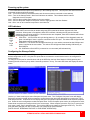
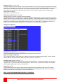
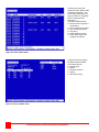
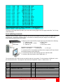
1
Xtensys CAT5 KVM SWITCH SYSTEM INSTALLATION AND OPERATIONS MANUAL 10707 Stancliff Road Houston, Texas 77099 Phone: (281) 933-7673 WWW.ROSE.COM LIMITED WARRANTY Rose Electronics warrants Xtensys™ system to be in good working order for one year from the date of purchase from Rose Electronics or an authorized dealer. Should this product fail to be in good working order at any time during this one-year warranty period, Rose Electronics will, at its option, repair or replace the Unit as set forth below. Repair parts and replacement units will be either reconditioned or new. All replaced parts become the property of Rose Electronics. This limited warranty does not include service to repair damage to the Unit resulting from accident, disaster, abuse, or unauthorized modification of the Unit, including static discharge and power surges. Limited Warranty service may be obtained by delivering this unit during the one-year warranty period to Rose Electronics or an authorized repair center providing a proof of purchase date. If this Unit is delivered by mail, you agree to insure the Unit or assume the risk of loss or damage in transit, to prepay shipping charges to the warranty service location, and to use the original shipping container or its equivalent. You must call for a return authorization number first. Under no circumstances will a unit be accepted without a return authorization number. Contact an authorized repair center or Rose Electronics for further information. ALL EXPRESS AND IMPLIED WARRANTIES FOR THIS PRODUCT INCLUDING THE WARRANTIES OF MERCHANTABILITY AND FITNESS FOR A PARTICULAR PURPOSE, ARE LIMITED IN DURATION TO A PERIOD OF ONE YEAR FROM THE DATE OF PURCHASE, AND NO WARRANTIES, WHETHER EXPRESS OR IMPLIED, WILL APPLY AFTER THIS PERIOD. SOME STATES DO NOT ALLOW LIMITATIONS ON HOW LONG AN IMPLIED WARRANTY LASTS, SO THE ABOVE LIMITATION MAY NOT APPLY TO YOU. IF THIS PRODUCT IS NOT IN GOOD WORKING ORDER AS WARRANTED ABOVE, YOUR SOLE REMEDY SHALL BE REPLACEMENT OR REPAIR AS PROVIDED ABOVE. IN NO EVENT WILL ROSE ELECTRONICS BE LIABLE TO YOU FOR ANY DAMAGES INCLUDING ANY LOST PROFITS, LOST SAVINGS OR OTHER INCIDENTAL OR CONSEQUENTIAL DAMAGES ARISING OUT OF THE USE OF OR THE INABILITY TO USE SUCH PRODUCT, EVEN IF ROSE ELECTRONICS OR AN AUTHORIZED DEALER HAS BEEN ADVISED OF THE POSSIBILITY OF SUCH DAMAGES, OR FOR ANY CLAIM BY ANY OTHER PARTY. SOME STATES DO NOT ALLOW THE EXCLUSION OR LIMITATION OF INCIDENTAL OR CONSEQUENTIAL DAMAGES FOR CONSUMER PRODUCTS, SO THE ABOVE MAY NOT APPLY TO YOU. THIS WARRANTY GIVES YOU SPECIFIC LEGAL RIGHTS AND YOU MAY ALSO HAVE OTHER RIGHTS WHICH MAY VARY FROM STATE TO STATE. IBM ®, AT, and PS/2 are trademarks of International Business Machines Corp. Microsoft ® and Microsoft Windows™ are registered trademarks of Microsoft Corp. Apple, Macintosh, and ADB are trademarks of Apple Computer, Inc. Sun is a registered trademark of Sun MicroSystems Inc. Any other trademarks mentioned in this manual are acknowledged to be the property of the trademark owner Copyright Rose Electronics 2006 - 2013. All rights reserved. No part of this manual may be reproduced, stored in a retrieval system, or transcribed in any form or any means, electronic or mechanical, including photocopying and recording, without the prior written permission of Rose Electronics. Rose Electronics Part # MAN-XS Printed In the United States of America Revision 3.5 TABLE of CONTENTS Contents Page # Disclaimer ........................................................................................................................................................................ 1 About this manual ............................................................................................................................................................ 1 Introduction ...................................................................................................................................................................... 1 Features ....................................................................................................................................................................... 2 Security .................................................................................................................................................................... 2 Flexibility .................................................................................................................................................................. 2 On-screen display technology .................................................................................................................................. 2 Upgradeability .......................................................................................................................................................... 2 Compatibility ............................................................................................................................................................. 2 Installation ................................................................................................................................................................ 2 Package content ...................................................................................................................................................... 2 Registration .............................................................................................................................................................. 2 System Overview ............................................................................................................................................................ 3 KVM user station ...................................................................................................................................................... 3 KVM Station Keyboard and Mouse .......................................................................................................................... 3 KVM Station Video Monitor ...................................................................................................................................... 3 Computers ................................................................................................................................................................ 3 CATx Transmitter ..................................................................................................................................................... 3 Cabling ..................................................................................................................................................................... 3 Keyboard Commands .............................................................................................................................................. 3 Site planning .................................................................................................................................................................... 4 Xtensys Models – Front View .......................................................................................................................................... 5 Typical Application .......................................................................................................................................................... 7 Xtensys System Installation ............................................................................................................................................ 8 Connecting the KVM station .................................................................................................................................... 8 Connecting the User Station to Xtensys Switch ...................................................................................................... 8 Connecting the Local KVM Station and Computers to Xtensys Switch ................................................................... 8 Powering up the system .............................................................................................................................................. 9 LED Indicators ............................................................................................................................................................. 9 Configuring the Xtensys Switch ................................................................................................................................... 9 OSD Menu Structure ..................................................................................................................................................... 10 Main Menu ................................................................................................................................................................. 11 Configure System ...................................................................................................................................................... 12 Configure Computers ............................................................................................................................................. 14 Configure KVM ....................................................................................................................................................... 15 Configure user ........................................................................................................................................................ 16 Configure Profile .................................................................................................................................................... 17 Configure Group ..................................................................................................................................................... 19 Configure Language............................................................................................................................................... 20 System status ......................................................................................................................................................... 21 Save configuration ................................................................................................................................................. 23 User Operating Instructions........................................................................................................................................... 24 Keyboard commands ............................................................................................................................................. 24 Alternative or third party switching ......................................................................................................................... 25 Video Setting Keyboard Commands ............................................................................................................................. 26 Status Commands ......................................................................................................................................................... 27 Serial port usage (RS232) ............................................................................................................................................. 29 Connecting the Serial Cable .................................................................................................................................. 29 Setting up Windows HyperTerminal....................................................................................................................... 29 Starting a serial communication session................................................................................................................ 29 Serial Device Features .............................................................................................................................................. 32 Serial switching commands ....................................................................................................................................... 33 Service Information ....................................................................................................................................................... 34 Maintenance and Repair ............................................................................................................................................ 34 Technical Support ...................................................................................................................................................... 34 Safety ............................................................................................................................................................................ 35 Safety and EMC Regulatory Statements ................................................................................................................... 35 Troubleshooting ............................................................................................................................................................. 36 Figures Page # Figure 1. Typical Application ........................................................................................................................................... 7 Figure 2. OSD Menu Structure...................................................................................................................................... 10 Figure 3. Main Menu ..................................................................................................................................................... 11 Figure 4. Configure System .......................................................................................................................................... 12 Figure 5. Configure Computers ..................................................................................................................................... 14 Figure 6. Configure KVM menu..................................................................................................................................... 15 Figure 7. Configure User ............................................................................................................................................... 16 Figure 8. Configure Profile ............................................................................................................................................ 17 Figure 9. Configure Group ............................................................................................................................................ 19 Figure 10. Configure language...................................................................................................................................... 20 Figure 11. Connection Status........................................................................................................................................ 21 Figure 12. Computer Status .......................................................................................................................................... 21 Figure 13. Video Status ................................................................................................................................................. 22 Figure 14. Device Status ............................................................................................................................................... 22 Figure 15. Save menu ................................................................................................................................................... 23 Figure 16. Computer select menu ................................................................................................................................. 25 Figure 17. CPU information........................................................................................................................................... 26 Figure 18. Connection Status menu ............................................................................................................................. 27 Figure 19. Computer Status menu ................................................................................................................................ 27 Figure 20. Video Status menu....................................................................................................................................... 28 Figure 21. Device Status menu ..................................................................................................................................... 28 Figure 22. Serial Options .............................................................................................................................................. 30 Tables Page # Table 1. Keyboard Commands ..................................................................................................................................... 24 Appendices Page # Appendix A. Initial factory default settings .................................................................................................................... 37 Appendix B. General specifications .............................................................................................................................. 38 Appendix C. Parts and cables ....................................................................................................................................... 39 Appendix D. Rack mounting.......................................................................................................................................... 40 Appendix E. Serial console protocol (Standard, Switch, Event configuration) ............................................................. 41 INTRODUCTION Disclaimer While every precaution has been taken in the preparation of this manual, the manufacturer assumes no responsibility for errors or omissions. Neither does the manufacturer assume any liability for damages resulting from the use of the information contained herein. The manufacturer reserves the right to change the specifications, functions, or circuitry of the product at any time without notice. The manufacturer cannot accept liability for damages due to misuse of the product or other circumstances outside the manufacturer’s control. The manufacturer will not be responsible for any loss, damage, or injury arising directly or indirectly from the use of this product. (See limited warranty) About this manual This manual covers the installation, configuration, and the operation of the Xtensys System. The Xtensys System consists of basically three components; the Xtensys switch, the Xtensys User Stations, and the Xtensys transmitters. Each component of the Xtensys system is described in this manual. The OSD section shows each of the OSD menus and their features. The Installation section describes how all components are interconnected to form a seamless switching network. The Operations section defines how to operate the system and all the user features available to make switching and maintenance simple and easy. Introduction ® Thank you for choosing Rose Electronics Xtensys™ CAT5 KVM Switch System. The Xtensys System is the results of Rose Electronics commitment to providing continued state-of-the-art switching solutions for today’s demanding workplace. The Xtensys System has proven to be a valuable investment for all types of businesses that have the need to monitor, maintain, and access information from multiple computer systems. Its use in large computer facilities gives the IT professional the added flexibility to monitor and maintain all systems, running on different platforms, from one or multiple KVM stations. The Xtensys CAT5 KVM Switch System is the common sense switching solution that provides the flexibility, expandability, and security required for today’s business environment. NOTE: A Keyboard, Video monitor, and Mouse are referred to through this manual as a KVM station Rose Electronics' Xtensys CAT5 KVM Switches are designed to configure to whatever your system demands are, one user or multiple users, two computers or thousands. All models offer standard features that allow for easy, secure, and complete access to as many computers or serial devices as your system has from one or multiple KVM stations. CATx cabling is used to connect to the computers and the user stations. This greatly reduces the cable bulk and makes installation easier, quicker, and less expensive. The Xtensys system takes the worry out of what type of CATx cabling is used and its lengths. Upon power-up it will automatically adjust the video gain and skew based on the CATx cable type and length, providing a crisp, clear display from all connected computers. The advanced on-screen display (OSD) menus are intuitive and easy to use. The menus guide you through the configuration process with on-screen information for each configuration section, making it easy to configure the Xtensys switch, the user stations, the computers, serial devices, and security for the system. There are additional configuration parameters that can be used to personalize the look of the menus and dialog boxes. A help line is provided for each menu selection giving a brief explanation of the selected menu item. Reliability, security, flash memory technology, versatility, and other advanced technological features ensure the Xtensys CAT5 KVM Switch System will streamline your data center or server room, simplify the maintenance, access and updating of your systems, and easily expand as your system demands increase. XTENSYS INSTALLATION AND OPERATIONS MANUAL 1 Features Security Unique configuration password for persons authorized to perform configuration maintenance. User names and passwords allow controlled access to computers with sensitive information, system data, or restricted applications Computers can be assigned to a unique group, allowing authorized access only Flexibility Extend the distance from the PC to the User stations up to 1,000 feet using industry standard CATx cabling The Xtensys design makes for easy installation, maintenance, and expandability All connections are made easy by using CATx cabling Switching to computers can be done by keyboard commands or a convenient on-screen list of computers Multi-language capabilities Switches have integrated auto-switching power supplies which accept 100-120/200-240 V sources On-screen display technology The Xtensys video pops-up over the computer application display or is automatically generated Easy to use menus guide you through the configuration process The connection status for all computers can be displayed Upgradeability Free lifetime base firmware upgrades, based on flash memory technology, provide new features and improvements. Base firmware upgrades are available from our web site at www.rose.com Compatibility A variety of hardware platforms can be connected simultaneously to the Xtensys switch without interference, including PCs, Sun systems, IBM RS/6000, HP, DEC, SGI, serial devices, and others Full keyboard and mouse emulation and video resolutions up to 1920 x 1440 ensures trouble-free access to most software applications Serial support using VT100, VT102, and VT220 terminal emulation Standard TTY mode automatically scrolls incoming data Installation The basic installation of the Xtensys system consists of: Connecting the user stations to the Xtensys KVM ports via CATx cable Connecting the CATx transmitter(s) to each of the computers to access Connecting the Xtensys switch to each computer via CATx cable Connect a local KVM station directly to the Xtensys switch for local access Once all cabling is completed, apply power and the Xtensys system will automatically adjust the video equalization and skew for all connected computers to produce a clean, clear display. Package content The shipping package content consists of the following: The Xtensys switch User Station(s) (as ordered) Rack mount kit Power cord (North American shipments only) ATRX Kit (CAB-04R005 / ACC-ATRX – for flash upgrading) Installation and operations manual If the package contents are not correct, contact Rose Electronics or your reseller, so the discrepancy can be quickly resolved. Registration Register your product for future updates by registering at http://www.rose.com/htm/online-registrationform.htm 2 XTENSYS INSTALLATION AND OPERATIONS MANUAL SYSTEM OVERVIEW System Overview The Xtensys switch is designed with the latest in KVM switching technology. It has the capability and flexibility to configure to most keyboards, video monitors, mice, servers, computers, and serial devices. The Xtensys switch provides the framework for a complete switching system. Remote users, computers, servers, and serial devices all interface to the Xtensys switch over CATx cabling. The Xtensys design makes the unit easy to install, and maintain. The complete system consists of the Xtensys switch, one or more user stations, CATx transmitters as required for each connected computer, and the computers, servers, and serial devices that will be connected. KVM user station A KVM user station, consisting of a Keyboard, Video monitor, and Mouse, connects directly to the corresponding connectors on the rear panel of the user station. A KVM station can also be connected directly to the Xtensys switch for local access to all connected equipment. KVM Station Keyboard and Mouse The keyboard and mouse that is connected to the user stations or local console are PS/2. USB keyboard and mouse connections are optional. KVM Station Video Monitor The KVM Station video monitor should be capable of supporting the resolution, frequency, and sync type being sent by all connected computer. It is recommended that the KVM monitor be a multi-sync monitor capable of resolutions up to 1280 x 1024 @ 75Hz or better. Computers The multi-platform support of the Xtensys switch makes it compatible with PCs (PS/2 or USB), UNIX systems, Sun, Mac, and compatible serial devices. CATx Transmitter Each connected computer uses a CATx transmitter that connects directly to the computer’s keyboard, monitor, and mouse ports. The CATx transmitter sends keyboard, mouse, and video signals via CATx cable to the Xtensys switch. The CATx transmitter’s video connector is HD15M and connects directly to the video out HD15F port on a computer. The keyboard and mouse connectors are available with PS/2 or USB connectors. The gain and equalization for different CATx cable lengths and the skew compensation will automatically be adjusted for perfect video with no manual adjustments. The Xtensys switch can support serial devices such as routers, hubs, and computers that require a serial interface. Cabling KVM user stations, computers and servers are easily connected to the Xtensys switch with industry standard CATx cables. Cables are usually purchased along with the Xtensys to provide quick, trouble-free installation. Provide adequate strain relief for the CATx cables to relieve excess tension on the connectors. Avoid routing cables close to fluorescent lights, air compressors, high voltage power sources and machinery that may create electrical noise or interference with the operation of the Xtensys switch. Interconnect cables should be solid-core type. Stranded patch cable will give poor results over longer distances. The pairing of the cable and pinning of its connectors should normally be in accordance with EIA-568B. Keyboard Commands Table 1 lists the available keyboard commands that can be issues to perform various tasks. Figure 11, 12, 13, 14, and 17 show the various status screens, cable length measurement, and the commands to fine tune the video amplification and equalization if needed. The red, green, and blue skew can be manually adjusted from this status screen. XTENSYS INSTALLATION AND OPERATIONS MANUAL 3 Site planning Organizing your site and planning the placement of the computers, the User stations, the Xtensys switches, and the routing of the cables is a key part in the installation and configuration process. Care should be taken when connecting the computers, user stations, and the Xtensys switches. Locate the Xtensys as close as possible to the computers so the cables are as short as possible but still give some freedom of movement. Up to a total of 1,000 feet of CAT5, CAT5e, or CAT6 industry standard cables can be used. The unique feature of Xtensys is that the length and type of cable will be automatically compensated for and the skew, equalization and gain automatically adjusted to provide the clearest possible display with no manual adjustments. The Xtensys switch can be rack mounted with Rose Electronics rack mount kit. Wherever the Xtensys is located, it should be on a secure surface, free from obstructions and objects that may cause damage to the Unit or an individual. Note: This product is also designed for IT power distribution systems with phase-to-phase voltage of 230V. Following are a few items to consider prior to installing or configuring the Xtensys switch: Determine which computer will be connected to CPU port #1, #2, #3, etc Identify which CPU ports will be connected to serial devices and configure those CPU ports for serial Each computer can be assigned a unique computer name. Names like staff, marketing, and finance make it easy to identify and connect to The default computer names are Computer x (x = 1 – 64) Pre-plan the CATx cable routing Define the responsible person for configuring and maintaining the system and assign them a configuration password Access to the system set-up and configuration menus can be limited by assigning a configuration password Access to the computers can be limited by assigning each user a unique user ID and password and configuring the switch to require a login Each computer can be assigned to a unique group and users can be given access to that group Rose Electronics Web Site Visit our web site at www.rose.com for additional information on the Xtensys system and other products offered by Rose Electronics that are designed for data centers applications, classroom environments and many other switching and extending applications. 4 XTENSYS INSTALLATION AND OPERATIONS MANUAL MODELS Xtensys Models – Front View Description / Indicators Model User station XTR-11 XTR-12 XTR-14 XTR-18 Power / Status Indicators Switch 8, 16, or 32 CPU ports Power / Status Indicators Switch 48 or 64 CPU ports Power / Status Indicators CATx Transmitter PS/2 / USB CATx Transmitter PS2/USB / Dual USB XTENSYS INSTALLATION AND OPERATIONS MANUAL 5 Rear View Models XTR-11 Description / Connectors User Station XTR-11 (1) RJ45 Link (2) USB (Kbd/Mouse) (2) PS/2 (Kbd/Mouse) (1) HD15F (Video out) (1) DB9M (Serial) (1) Power XTR-12 (2) RJ45 Link (2) USB (Kbd/Mouse) (2) PS/2 (Kbd/Mouse) (1) HD15F (Video out) (1) DB9M (Serial) (1) Power XTR-14 (4) RJ45 Link (2) USB (Kbd/Mouse) (2) PS/2 (Kbd/Mouse) (1) HD15F (Video out) (1) DB9M (Serial) (1) Power XTR-18 (8) RJ45 Link (2) USB (Kbd/Mouse) (2) PS/2 (Kbd/Mouse) (1) HD15F (Video out) (1) DB9M (Serial) (1) Power XTR-12 XTR-14 XTR-18 A = PS/2 – HD15 Local KVM ports B = RJ11 for Flash upgrading C = RJ45 connectors to Computers D = RJ45 connectors to User station Switch The 1U chassis can be configured with: 1. 1 Local KVM input (A) 2. 1 or 2 Serial inputs (B) 3. 4, 8, 16, or 32 CPU connectors (C) 4. 0, 2, 4, or 8 KVM connectors (D) A = PS/2 – HD15 Local KVM ports B = RJ11 for Flash upgrading C = RJ45 connectors to Computers D = RJ45 connectors to User station Switch The 2U chassis can be configured with: 1. 1 Local KVM input (A) 2. 1, 2, 3 or 4 Serial inputs (B) 3. 8, 16, 32, 48 or 64 CPU connectors (C) 4. 0, 2, 4, 8, or 16 KVM connectors (D) NOTE: The local KVM connection (A) shares a common video path with the remote KVM connection port #8 (D). It is recommended that when the local KVM is going to be used, the local user check to assure that KVM port #8 is not in use by a remote user. This can be easily observed by pressing and releasing the left control (Ctrl) key, then the ESC key, then F2 (Connections). A list of all CPU ports and their status will display (See Figure 11). Check if KVM station #8 is connected to a computer name. If so notify the remote user on KVM port #8 that you are going to connect to a CPU port and for them to save their work and disconnect. 6 XTENSYS INSTALLATION AND OPERATIONS MANUAL Typical Application Up to a total of 1,000’ of CATx cable The flexibility of the Xtensys system enables it to configure to almost any system environment. The User Station is available with one local KVM Station connectors and 1, 4, or 8 RJ45 link ports. Xtensys Switch Xtensys User Station The Switch is available with one local KVM station connectors, 0, 2, 4, 8, or 16 remote KVM connections, and 8, 16, 32, 48, or 64 RJ45 CPU ports. All connections from the User Station to the Switch and from the Switch to the computers, servers, and serial devices use CATx cabling. The total CATx cable length from the User Station to the Switch and from the Switch to the connected computers is 1,000 feet max. User KVM Station Figure 1. Typical Application XTENSYS INSTALLATION AND OPERATIONS MANUAL 7 INSTALLATION Xtensys System Installation User Station (See note below) Connecting the KVM station The KVM station connects directly to the Xtensys User Station. The KVM stations keyboard, monitor, and mouse cables connect directly to the corresponding connectors on the User station. The KVM keyboard and mouse can have PS/2 or USB connectors. The monitor should be equal or better in resolution and capability than any of the connected computers. Connecting the User Station to Xtensys Switch KVM Station Xtensys Switch Xtensys User Station The user stations connect directly to the Xtensys Switch using industry standard CATx cable. Depending on the User Station and Switch model used, up to 8 different Xtensys Switches can be connected to from a single User Station. Connecting the Local KVM Station and Computers to Xtensys Switch A local KVM station can be connected directly to the Xtensys switch. This provides direct local access to all connected equipment. CATx cable from transmitter to Xtensys switches CPU port Each computer, server, or serial device that is connected to the Xtensys switch must have an Xtensys Intelligent Information Module Transmitter installed. This connects directly to a computers HD15 video port and the PS/2 or USB keyboard and mouse ports. The transmitter is then connected to an Xtensys switches RJ45 CPU port using industry standard CATx cable. Local KVM Station NOTE: The Xtensys User Station, configured with 4 or more link ports, can be installed several different ways. The most common installation is to connect each of the link ports (RJ45) to different Xtensys switches. The link port can also be connected directly to a standalone computer with an Intelligent Information Transmitter installed. This gives the option of connecting to an Xtensys switch or your local desktop system. Switch User station Desktop 8 Intelligent Information Transmitters connected to each computer KVM station XTENSYS INSTALLATION AND OPERATIONS MANUAL Powering up the system It is recommended that the system be powered up in the following sequence. This sequence will assure that all the connected equipment will boot properly. First – Turn on all monitors (Local KVM monitor and all remote monitors connected to user stations) Next – Turn on the Xtensys switch. Wait for all indicators to stabilize. This indicates that the internal diagnostic check is complete Next – Connect the provided power adapter to the user stations Next – Connect the power adapter to the power source to apply power to the User Stations Last – Boot / turn on all connected computers or serial devices. LED Indicators CPU, KVM, or Serial LED Each RJ45F connector has an amber and green LED located at the bottom right and left of the connector. When power is first applied, these LED’s will flash, indicating the self test and internal diagnostic check is being performed. Once these tests are completed, these LED indicators will indicate the following status or information: CPU LED’s - All CPU LEDs will cycle during power up. On completion of the diagnostic tests, the green Led will light if there is a device connected to that CPU port. The amber LED will light and will flash showing activity at that CPU port KVM LED’s – The Green LED will light when there is a user station connected to that KVM port and power is applied to the user station. The amber LED will light and flash showing KVM activity on that KVM port ALL KVM and the Serial LED’s (connected or not connected) will laminate dimly. Configuring the Xtensys Switch The Xtensys switch must have the CPU ports configured for either a UTP connection or a Serial connection. The default configuration is UTP. Only the CPU ports that are connected to a serial device have to be configured for serial functions. To configure a CPU port for serial functions call up the OSD from the local User Station’s KVM by pressing and releasing the left control key, they within 2 seconds, press the F12 key. The main OSD menu will display as shown below. Use the up / down arrow keys to select Computer and press enter. The “Configure Computer” menu will display. Select the computer port that will be connected to a serial device then press the right arrow key to tab to the “Type” field and press enter. A selection box will display listing the configuration options available for the selected computer port. Select the serial configuration needed and press enter. If other Computer ports need to be configured for serial, select those computers and configure them in the same manor. When complete, press the “Esc” key to return to the main menu, select “Save” and press enter. Then exit the OSD menu system by pressing the ESC key. The CPU ports that were changed from UTP to Serial are now configured for serial functions. (NOTE: DO NOT PROGRAM CPU PORT #1 FOR SERIAL OPERATION) XTENSYS INSTALLATION AND OPERATIONS MANUAL 9 SYSTEM CONFIGURATION MENUS OSD Menu Structure Xtensys Menu Structure Main Menu System Computer System settings Configure password Global address Serial console protocol Keyboard settings Hotkey PC keyboard rate PC Keyboard delay Sun keyboard language Appearance Menu color scheme Screen saver Screen saver time Background color Text color Position Fadeout Status Computer name Type Save KVM name Resolution Start User User User name Password Profile Use only the numeric key above the keyboard for entering numbers. The numeric keypad will not work for entering numbers. Language KVM Name CPU Name User Connect / Disconnect KVM Menu language selection Group Profile Configure group / computer access Profile name Access Mode Share Scan Logout Exit Figure 2. OSD Menu Structure To invoke the Menu System, from the local KVM station or a user station, press and release the left Ctrl key, then within 2 seconds, press the F12 key. The Main OSD menu will display. Use the up / down arrow keys to select the section needed and press enter. When you select (highlight) a menu section that section’s menu will display, an input text box will display for a new value, or a list of supported choices will display. Enter or select the information needed and press [Enter]. Press Esc to return to the previous page or abort an input. All changes are only temporary. Once power is removed, the changes are aborted unless they have been saved. NOTE: Saving configuration changes from user stations to an Xtensys switch is limited to XTR-11 user stations only. Saving the configuration items to an Xtensys switch is not possible from an XTR-12, or XTR-14 User Station 10 XTENSYS INSTALLATION AND OPERATIONS MANUAL Main Menu Figure 3. Main Menu Save all changes made. If not saved, changes will be lost when power is removed from a Unit. The Main configuration menu is the starting point for the configuration menus. From this menu, you can configure the System, Computers, KVMs, Users, Profiles, Groups, and Languages. The connection Status for all connected equipment can be displayed. The “Save” section saves any changes and “Exit” will quit the OSD system and return to normal operation. To display the “Main menu”, press and release the left control [Ctrl] key, then, within 2 seconds, press the F12 key. Command characters following the press and release of the left control [Ctrl] key, like the F12 key, must be entered within 2 seconds or the command is aborted. All numeric inputs to the menu system must be done using the numeric keys above the keyboard. The numeric keypad cannot be used for entering numbers. Keyboards that do not have separate page up and page down keys, the page up and page down keys on the keypad can be used for scrolling through the menu pages. The main menu will display on top of a currently connected computers video. If no computer is connected to supply the video, the display’s background is black. The following pages explain each of the Xtensys menus and the options available. XTENSYS INSTALLATION AND OPERATIONS MANUAL 11 Configure System Figure 4. Configure System Selecting “System” from the main menu displays the “Configure System” menu. This menu allows you to configure the System, KVM keyboard settings, and Appearance settings. Each “Configure system” section is explained below. “System settings” Configure password (Default: no password) The “Configure password” selection is used to add a new or change an existing configuration password. This password prevents unauthorized access to the configuration menus. Passwords are case sensitive, 8 characters max. To create or change a password, select “Configure password” and press [Enter]. An input box will display to enter the password. Type in the password and press [Enter]. When the menu system is called up, (Left Ctrl, F12) this password must be entered to gain access to the configuration menus. NOTE: If the password is lost and the system reset to factory defaults, all inputs (computer names, user names, etc.) will be reset to factory defaults. Global address (Default: 0) This function is currently not implemented and will be added later. Serial console protocol (Default: Standard) Standard, Switch, or Events (See Appendix E for a complete description and application example) “Keyboard settings” Hot key (Default Left Ctrl) - Defines the hot key sequence to invoke the menu system and computer select display. The Hot key options are: Left Ctrl Right Ctrl Print screen Scroll lock Rate (chars/sec) (Default: 20) / Delay (Default: Fast) This option adjusts the KVM keyboard action when you hold down a key to repeat a single character. Valid inputs are 1-31. 12 XTENSYS INSTALLATION AND OPERATIONS MANUAL Sun keyboard language (Default: US) Determines the response to a Sun computer’s query for the keyboard language type used. To change the Sun keyboard language type, select it and press [Enter]. A selection box will display showing the supported Sun language choices. Use the up/down arrow keys to select the desired language and press [Enter]. The Sun keyboard language choices are: US Espanol US-Unix Svenska/Suomea Francais Franco-Suisse Dansk Schw-Deutsch Deutsch United Kingdom Italiano Hankuko Nederlands Tai-oan Norsk Nihongo Portugues Canadienne “Appearance settings” Menu color scheme (Default: Night sky) Sets the colors for the configuration menus. To change the color scheme, select “Menu color scheme” and press [Enter]. A selection box will display showing the supported color schemes. Use the up/down arrow keys to select the desired scheme and press [Enter]. The menu color schemes choices are: Night Sky – cyan, magenta, white, and blue Tuxedo – black, red, and white Aquarium – yellow, magenta, blue, cyan, and white Forest – green, black, cyan, and blue Screen saver (Default: Weaving) A screen saver reduces monitor burn-in and adds an additional level of security. The screen saver automatically activates when there is no keyboard or mouse activity for an adjustable period. To change the screen saver type, select it from the menu and press [Enter]. A selection box will display showing the supported screen saver choices. Use the up/down arrow keys to select the desired screen saver and press [Enter]. The screen saver choices are: Black screen Fireflies Weaving Bounce Screen saver time (seconds) (Default: 1800 seconds) Determines the period of keyboard or mouse inactivity before activating the screen saver. To change the screen saver time, select it from the menu and press [Enter]. An input box will display to enter a new screen saver time. Enter a new value from 1 to 9999 seconds and press [Enter]. Entering a value of 0 (zero) disables the screen saver. Background color / Text color (Default: Background = Cyan / Text = Black) The color choices are: This option sets the background or text colors for the connection status and computer select screens. Colors can be one of eight solid or transparent colors. To change the background or text color, select it from the menu and press [Enter]. The color selections will display showing the solid and transparent color choices. Use the arrow keys to select the desired color and press [Enter]. Note: Do not set the background color and text color the same, you will see nothing but that color screen. XTENSYS INSTALLATION AND OPERATIONS MANUAL 13 Position (Default: X = 25, y = 45) This option adjusts the screen position of the connection status box. Once set, this position is maintained at all video resolutions. To change the connection status box position, select it from the menu and press [Enter]. Use the arrow keys to position the status box anywhere on the screen and press [Enter] when the desired position is reached. Do not set the screen position off the visible screen area. This could cause rainbows or bars of shaded video. Valid position ranges are: Horizontal: 0 – 64, Vertical: 0 – 99 Fadeout (seconds) (Default: 5 seconds) Sets the amount of time the connection status box displays. Valid fadeout times are 0 – 255 seconds. A value of zero disables displaying the connection status box; a value of 255 will cause the connection status box to always be displayed. If the connection status box does not display when switching to a computer, increase the fadeout time. Some monitors will not display the connection status box if the fadeout time is less than the time it takes the monitor to sync to a new video signal. To change the fadeout time, select it from the menu and press [Enter]. Enter a valid new time in seconds and press [Enter]. Configure Computers Figure 5. Configure Computers The “Configure computer” menu allows you to change each selected computers name and type. The left (untitled column) indicates the logical location (RJ45 port) that a computer is connected to. Computer name (Default: Computer x) To change the computer name, select it from the menu and press [Enter]. An input box will display to enter a new computer name. Type in the new name and press [Enter]. Names can be 16 characters in length, case sensitive. Use the page up/down keys to show more computers. Type (Default: UTP) The type field defines to the system how the external equipment will be connected to each port, UTP or Serial. Selecting the type field for a selected computer and pressing enter will display the selection choices for that port. Select UTP or one of the serial options for each CPU (RJ45) port. NOTE: DO NOT PROGRAM COMPUTER PORT #1 FOR SERIAL 14 XTENSYS INSTALLATION AND OPERATIONS MANUAL Configure KVM Figure 6. Configure KVM menu The “Configure KVM” menu allows you to change KVM name, resolution, start, and user parameters. KVM name (Default: KVM Local) To change the KVM name, select it from the menu and press [Enter]. An input box will display to enter a new KVM name. Type in a new name and press [Enter]. KVM names can be 16 characters in length, case sensitive. Resolution (Default: 640x480@60Hz) Selects the resolution and refresh rate of the on-screen display when no attached computer video is present. If a computer video is shown, the detected video resolution from the connected computer is used. To change the resolution select the resolution field and press [Enter]. A list of supported resolutions will display. Select the new resolution from the list and press [Enter]. The supported resolutions are: 640x480@60Hz 640x480@72Hz 640x480@75Hz 640x480@67Hz 832x624@75Hz 1152x900@66Hz 1152x900@76Hz Start (Default: 0) Assigns the CPU port number the KVM station will connect to on start up and login. 0 = no connection. To change the value, select it from the menu and press [Enter]. Type in the CPU port number the selected KVM station will connect to upon start up or login and press [Enter]. User (Default: User xx) This field is used to assign a specific user to a KVM station. To change the user select the user field and press [Enter]. A selection box will display a list of user names followed by “Login”. Select a user or Login and press [Enter]. If “Login” is selected, the KVM user must login with their user ID and assigned password to gain access. The configure user, profile, and group menus all tie together to provide access control to the computers. A group defines which computers in the system can and cannot be accessed. This group is assigned to a profile name which defines how the computers (defined by the group) can be accessed. The profile is then assigned to a user or users. XTENSYS INSTALLATION AND OPERATIONS MANUAL 15 Configure user Figure 7. Configure User The configure user menu is used to define a user name, assign an access password, and assign a specific profile to the user. Duplicate names are acceptable; however, all persons using the same user name will have the same access rights. User name (Default: User xx, where x = 1 to 64) To change a user name, select it and press [Enter]. An input box will display. Type in a new user name and press [Enter]. (8 characters max. case sensitive) Password (Default: no password) This field assigns a unique password to a selected user. Any user station that has “Login” enabled, the user must enter their username and password to gain access to the station. To assign or change a user password, select the user, then the password field and press [Enter]. An input box will display. Type in a password for the selected user and press [Enter]. Passwords can be up to 8 characters in length and are case sensitive. Profile (Default: Profile x, where x = 1 to 64) This field is used to assign an access profile to a selected user. Profiles can be defined to limit the type of access to the computers. To change an assigned profile for a selected user, first select the user, and then select the profile to change and press [Enter]. A selection box will display listing the profiles available. Select the profile to assign to the selected user and press [Enter]. Use the page up/down keys for more profiles. Profiles are defined on the “Configure profile” menu. 16 XTENSYS INSTALLATION AND OPERATIONS MANUAL Configure Profile Figure 8. Configure Profile The configure profile menu is used to assign computer access levels, modes, share, scan and logout times. Name (Default: Profilxx, where xx = 01 to 64) The profile name can be changed to any name up to 8 characters in length. The name can be a specific user, a group of users within a department, a business department, or any name that defines the profile. To change the profile name, select the one to change and press [Enter]. An input box will display. Type in a new profile name and press [Enter]. Access (Default: Groupxx, where xx = 1 to 64) This field is used to assign each profile to a group. To change the access for a selected profile, select the profile to change then select the group to change and press [Enter]. A list of groups will display. Select the group that has been set-up for the selected profile and press [Enter]. A group is set up on the configure group menu. Mode (Default: Share) This field assigns 1 of 4 modes to a profile. To change the mode, select the profile to change the mode, and then select the mode to change and press [Enter]. A selection box will display. Select the mode needed and press [Enter]. The modes are: View – Profiles set to the view mode allow users to switch to any computer, but have only view privileges. Share – Profiles set to the share mode allow users to take keyboard and mouse control of a computer on a first come, first serve basis. Control of the computer is based on the time-out value entered in the share column. Control – Profiles set to the control mode allow users to take exclusive control of a computer. No time-out value is invoked. Other users that try to connect to the same computer can only view the video. They have no keyboard or mouse control until the user with the control disconnects from the computer. Private – This mode is the same as the control mode except other users cannot view the video or access the computer. Share (Default: 2 seconds) This feature allows other users to take keyboard and mouse control of a computer after a specific time of no keyboard or mouse activity by a user. To change the Share time for a given profile, select the profile, then the Share to change and press [Enter]. An input box will display. Type in a new share value in seconds and press [Enter]. Valid share values are 0 to 9999 seconds. The share value is only valid if the profile mode is share. XTENSYS INSTALLATION AND OPERATIONS MANUAL 17 Scan (Default: 5 seconds) When a user invokes the scan function, this feature sets the time the video is displayed before switching to the next sequential computers video. To change the scan rate, select the profile, then the scan rate to change and press [Enter]. An input box will display. Type in a new scan time and press [Enter]. Valid scan times are 0 to 9999. If the video is not present during the scan mode, the scan value may be set to low and the monitor cannot synchronize to the video fast enough to display it. This usually happens with a scan value of 4 or lower. If this problem occurs, increase the scan value. 0 (zero) is a valid entry but not recommended. Logout (Default: 240 minutes) This setting disconnects and logs out a user after the set period of no keyboard or mouse activity. To change the logout value, select the profile, then the logout time to change and press [Enter]. An input box will display. Type in a new logout time and press [Enter]. Valid times are 0 to 9999 minutes. A value of 0 (zero) disables the automatic logout function. If login is enabled for a KVM station, but the Logout time is set to zero, the user remains logged in until they manually log out using the [Ctrl] L command. 18 XTENSYS INSTALLATION AND OPERATIONS MANUAL Configure Group Figure 9. Configure Group The configure group menu allows you to assign a computer to one or more groups. Users that are assigned a profile that contains a specific group name can only access the computers within that group. It they try to access a computer that is not within the assigned group, the error “Not in access group” will display in the connect box. The left computer column displays the computer names. To change a group name, select it and press [Enter]. This menu is an array of groups (x) and computers (y). Moving the arrow key to the right from one plus (+) to another plus (+) for a selected computer name changes to the next group. A plus (+) means the computer belongs to that group, a blank means the computer is not in that group and cannot be accessed by a user assigned to this group. To change the group membership, select the group for a selected computer and press the space bar to toggle between the two states, + or blank. Default: (All computers in all groups) The configure user, profile, and group menus all tie together to provide access control to the computers. A group defines which computers in the system can and cannot be accessed. This group is assigned to a profile name. The profile defines how the computers (defined by the group) can be accessed. The profile is then assigned to a user or users. XTENSYS INSTALLATION AND OPERATIONS MANUAL 19 Configure Language Figure 10. Configure language Selecting “Language” from the “Main” menu displays a choice box with 6 different language options. Select the language needed and press [Enter]. This changes all the menus and displayed information to that selected language. The language options are: English Francais Deutsch Espanol Italiano Portugues 20 XTENSYS INSTALLATION AND OPERATIONS MANUAL System status The system status display is a very powerful and useful tool for monitoring, troubleshooting, and reporting the connection status, computer status, video status and device status. The status screens display reported information from all devices connected in the system. Connection status display This screen displays: The KVM name The CPU name the KVM is connected to The User name The connect / disconnect status From any status screen, press: F2 for Connection status, F3 for Computer status F4 for Video status F5 for Device status ESC to Exit Figure 11. Connection Status The computer status display reports the firmware version (FM column) of the CATx transmitter connected to each computer. The uptime, CATx transmitter voltage, CATx transmitter temperature and users are also reported. Figure 12. Computer Status XTENSYS INSTALLATION AND OPERATIONS MANUAL 21 Pressing the F4 key displays the video status of all connected computers. The video resolution, refresh rate, number of horizontal lines, and the CATx cable distance is reported for each connected computer. Figure 13. Video Status The Device status screen provides information concerning the Xtensys Switch. The Switch name, the global ID, and the uptime is also reported. Each Xtensys switch component will report the installed firmware revision (If applicable) to this screen. The Activity column indicates the communication status between all installed boards. Figure 14. Device Status 22 XTENSYS INSTALLATION AND OPERATIONS MANUAL Save configuration When changes are made to any configuration, they must be saved in flash memory to insure that the changes will be active after a power cycle. To save the settings, select save and press [Enter]. A YES/NO selection box will display. Choose “YES” to save the changes to flash memory on all powered-on Xtensys switches. Choose “NO” for temporary or incorrect changes. The temporary settings will only be in effect as long as power is applied to the Unit. Once power is cycled, unsaved changes are lost and the previously saved configuration settings will be effective. Figure 15. Save menu XTENSYS INSTALLATION AND OPERATIONS MANUAL 23 User Operating Instructions The following instructions apply to all Xtensys switches and user stations. This section explains the operating functions of the on-screen displays, the login procedure, connect procedure and other commands needed to easily use the Xtensys switch and its capabilities. To start using your Xtensys switch, you first need to become familiar with the keyboard commands. The available keyboard commands are shown in the table below. All keyboard commands start with an attention sequence by pressing and releasing the left [Ctrl] key, then the additional command characters. The additional command characters must be entered within two seconds of each other or the command is aborted. Commands are not case sensitive and are shown in upper or lower case for clarity only. Do not use the [SHIFT] key or the numeric keypad to enter any commands. [Ctrl] in Table 1’s, Key Sequence column is a press and release function of the left [Ctrl] key. The Ctrl Hot Key can be changed using the configure system menu to: Left Ctrl Right Ctrl Print screen Scroll lock If the HOT KEY has been changed to one of the above four, substitute the new key for [Ctrl] in the below table. Keyboard commands Command Key Sequence Description Main Menu CPU List * Direct CPU connect * Direct CPU connect * Connect Back [Ctrl] [F12] [Ctrl] [Esc] [Ctrl] n [Enter] Displays main menu Displays CPU selection list Connects directly to the specific CPU number “n” from the local KVM station or from an XTR-11 user station Connects directly to the specific CPU number “c” from an XTR-12/14 user station (n=RJ45 port # on user station / c = CPU port # on Xtensys switch) Connects to the previous CPU Connect Down Connect Up KVM Status Logout Disconnect Reset Keyboard/ mouse Send Null Byte [Ctrl] [Minus sign] [Ctrl] [Plus sign] [Ctrl] D [Ctrl] L [Ctrl] Q [Ctrl] R [Ctrl] n [Tab] c [Enter] [Ctrl] [Backspace] [Ctrl] N Reset Mouse (NT [Ctrl] O (not zero) or Unix systems only) Start Scan [Ctrl] S Stop Scan [Ctrl] X Connects to the previous sequential CPU in a Group. Connects to the next sequential CPU in a group Displays / Removes status box. Logs user out if the KVM station is configured for user logins. Disconnects the current CPU Resets / enables keyboard and mouse; enables PS/2 mouse on connected CPU Sends a null byte to the CPU’s PS/2 mouse port. Use this command if the PS/2 mouse gets “out of sync”. Resets the currently selected NT or Unix computers PS/2 mouse. Also switches the NT mouse driver to “wheel” mode. Sequentially steps through all connected CPUs in a group. Turns scan “Off” Table 1. Keyboard Commands * The CPU list and Direct CPU connect functions vary depending on the configuration of your system. The CPU list will automatically adjust to the type of user station (XTR-11, XTR-12, or XTR-14) and to the number of CPU ports on the Xtensys switch. Refer to Figure 16 for an example of the CPU list display. 24 XTENSYS INSTALLATION AND OPERATIONS MANUAL Operating Instructions When you first start using a user station, it may require you to login. If the user station requires a login, a login box will display. The login box appears when a Unit is powered on, when a user logs off, or when a preset time interval passes with no keyboard or mouse activity. If a login is required, type in your User ID and press [Enter]. (User ID is the user name defined on the configure user menu) If the user ID is validated, you can then type in your password and press [Enter]. If the password is validated, the user station can be accessed. A user may login with the same user ID and password at more than one user station. Both the User ID and password are case sensitive. Once you have access to a user station, you can switch to any of the connected computers provided your security profile allows access to that computer. To connect to a computer, you can use the “Direct CPU Connect” keyboard command or the “Computer select” menu. Figure 16 shows the Computer select menu. This menu is created from the system configuration. The configuration used to produce the below menu is an XTR14 user station (4 port) and a 4 x 8 Xtensys switch. To invoke this menu, press and release the left Ctrl key, then press the Esc key. The first column indicates the Port # on the user station followed by the CPU port # on the Xtensys switch. Selecting 01-01 will connect port #1 on the user station to port #1 on the Xtensys switch. The computer connected to port #1 on the Xtensys switch would display on the user station’s monitor and the keyboard and mouse would control that computer if authorized to do so. Using the page up or down arrow keys will display more computers. In this configuration, pressing the page down key would display user port 03-01 thru 03-08 and 04-01 thru 04-08. If the configuration was an Xtensys switch with 64 CPU ports, this screen would expand to show 01-01 thru 01-64, 02-01 thru 02-64, 03-01 thru 03-64, and 04-01 thru 04-64. Figure 16. Computer select menu Alternative or third party switching The Computer Select menu allows you to perform alternative or third party switching. This alternative switching is where, from the local KVM, you can switch any KVM station to any CPU port. On the Computer Select Menu in the top row of the lower menu, there is the label KVM Local. This is the KVM station that will switch to a selected computer. To perform this alternative switching: 1. Display the computer select menu (Right Ctrl key + ESC key) 2. Press tab key to select the KVM station to switch 3. Press the up / down arrow keys to select the Computer to switch the KVM station to 4. Press enter to switch all functions (keyboard/mouse/video) or Press “V” to switch only the video From the Computer select screen you can also obtain additional CPU information. Use the up / down arrow keys to select a computer, and then press the right arrow key. The screen shown in Figure 17 will display showing the gathered information for that computer connection. XTENSYS INSTALLATION AND OPERATIONS MANUAL 25 With this menu displayed, pressing the “M” key will toggle the temperature and distance units from Feet and Fahrenheit to Meters and Celsius. This change affects all menus. Once changed, press the ESC key to exit this menu. Next press the left Ctrl key plus the F12 and choose “Save” to save this change. NOTE: Making this change from a user station only changes the OSD units for that user station. Making this change from the local KVM station will change all connected user stations when power is cycled on either the Xtensys unit or a user station. Figure 17. CPU information Video Setting Keyboard Commands Video amplification, equalization, red skew, green skew, and blue skew can be adjusted if needed using simple keyboard commands. To adjust these components, first invoke the computer select OSD by pressing the left control key, then the escape key. Use the up or down arrow keys to select (highlight) the computer connection that needs adjusting, and then press the right arrow key. The selected computer information window shown above will display showing the present values for all settings. To make any adjustments, first execute the below keyboard command for the adjustment needed, then use the keypad + and – keys to increase or decrease the value. For example, to adjust the Red skew, first display the computer select screen (Ctrl – Esc). Select the computer to adjust the red skew and press the right arrow key. Next press and release the right Ctrl key then press the r key. A selection indicator will display next to the Red skew text. Use the + and – key on the keypad to increase or decrease the Red skew. Adjustment Amplification Equalization Red skew Green skew Blue skew Keyboard Command right Ctrl a right Ctrl e right Ctrl r right Ctrl g right Ctrl b Make sure the computer select window is open and the CPU info window is displayed prior to issuing the commands. When changes have been made, escape out of the menu to the main computer screen and then press Ctrl + F12 to display the main menu. Tab to “Save” and save the changes. Changes must be saved or they will be lost if power is removed from Xtensys. 26 XTENSYS INSTALLATION AND OPERATIONS MANUAL Status Commands The connection, computer, video, and device status can be checked by starting the computer select menu. Press the left control key, then the ESC key to display the menu. Function keys F2, F3, F4, and F5 display the status information as shown in Figure 18. Pressing the F2 key displays the connection status. This display screen shows: A list of all KVM stations What computer each KVM station is connected to What user is logged on to that station If the KVM is connected or disconnected and if connected, the amount of time the station has been connected. Figure 18. Connection Status menu Pressing the F3 key will display the status of the connected computers. The status information will only be shown for computers that are connected and powered on. The status window shows: The port each computer is connected to List of computers by name The firmware version Uptime Voltage Temperature Users Figure 19. Computer Status menu XTENSYS INSTALLATION AND OPERATIONS MANUAL 27 Pressing the F4 key will display the video status of the connected computers. The video status information will only be shown for computers that are connected and powered on. The status window shows: The port each computer is connected to List of computers by name The resolution detected Frequency Actual number of Lines CATx cable length from computer to Xtensys Figure 20. Video Status menu Pressing the F5 will display the Device status window. This window shows: Device name Uptime Firmware versions Activity OSD F/W version Figure 21. Device Status menu 28 XTENSYS INSTALLATION AND OPERATIONS MANUAL SERIAL FEATURES Serial port usage (RS232) The serial port on both the Xtensys switch (RJ12) and the User station (DB9) are used to update the unit’s firmware. The following procedure for establishing a connection from your standalone computer or Notebook computer to the Xtensys switch’s serial port or a User station uses Windows HyperTerminal™. Refer to your user’s manual if a different communication program is being used. To access an Xtensys serial port, the following items are required: A serial cable (RJ12 connector and an appropriate adapter for the computer's serial port). The serial cable and adapter are provided with each Xtensys switch (Rose part number KIT-ATRX). A standard DB9 null modem cable can be used to flash user stations. A dedicated computer, Notebook computer with a serial port, or a display terminal. Using a display terminal will allow you to configure the Xtensys switch; however, you will not be able to upgrade new versions of firmware. The computer or Notebook must not be attached to any Xtensys switches in the system being upgraded. A communications program such as Windows HyperTerminal. Connecting the Serial Cable Attach the serial cable from the RS232 port on the Xtensys switch (RJ12 connector) to the COM1 port (DB9M) on your computer. This COM1 port must be the same communication port your communication software is configured for. If your communication software is configured for COM2 then connect the cable to this DB9M port. Setting up Windows HyperTerminal (The following instructions are using Windows HyperTerminal. The instructions may be different for other operating systems or communication program) Start the Windows HyperTerminal program. The “New Connection” dialog box will display requesting a name for this session. Enter a session name like “Xtensys serial option” and click ‘OK”. Next, the “Connect To” dialog box will display. Click on the “Connect Using” down arrow to display the connect options. Select the COM 1 option, then click “OK”. The COM1 properties dialog box will display. Using the drop-down selection boxes, select the following values for each setting. Bits per second 115200 Data bits; 8 Parity; None Stop bits; 1 Flow Control; None Click “OK” when all values have been entered. The HyperTerminal dialog box will display and information can be exchanged with the Xtensys switch properly. You can save this setup so the next time its needed, you can select the ICON with the name you gave it and these settings will already be established. Starting a serial communication session Verify that “Connected” appears in the bottom left corner of the HyperTerminal window. If “Connected” is not present, click on the “Call” icon. “Connected” should display in the bottom left corner. Power on or cycle power on the Xtensys switch and press the spacebar when the message, “Hit the spacebar within 1 second to get serial options menu” appears on your screen. The serial menu will appear after the diagnostic check completes. The serial menu enables you to perform flash upgrades. Following explains the serial menu options: XTENSYS INSTALLATION AND OPERATIONS MANUAL 29 Figure 22. Serial Options Option 1. Receive new main program from serial port (This card only) When a new main program is available, it can be obtained from Rose Electronics or downloaded from our web site at www.rose.com. The diagnostic screen that is displayed when the Xtensys switch is first turned on shows the main program version that is presently installed. You cannot update the flash memory using only a display terminal; you must use a standalone computer or Notebook and the new main program saved on that computer. To load a flash upgrade file, type 1 in the Enter choice field of the serial options menu. The following message will appear: Waiting for file......................... Send the program file from your computer to the Xtensys using ASCII text file protocol. From HyperTerminal, click on “Transfer” and select “Send Text File”. The “Send Text File” dialog box will display. Enter the file name of the updated firmware file into the File Name box and click “Open”. The file transfer function will start. While the file is being sent, periods are sent to indicate the copying progress. Once the file has been sent, you will see the message: Receive successful Flash programming......................... Flash programming successful After the flash memory is programmed, the serial menu will display. Updating the firmware program does not change any of the custom settings that have been made. 30 XTENSYS INSTALLATION AND OPERATIONS MANUAL You may receive one of the following errors during the file transfer function: checksum error, record error, or data error. These messages are followed by: Receive failed Try again Y/N These error messages may be caused by any of the following items: Corrupted firmware upgrade file. Loose or defective RS232 cable. RS232 protocol not configured correctly. Bad transmit or receive levels. Hardware problem on transmit or receive side. Identify and correct the transmit problem and press “Y”, then [Enter] to try again. Press “N” and then [Enter] and the prompt "Hit enter to boot” appears. Press the [Enter] key to re-start the Xtensys switches diagnostics with the firmware unchanged. Option 2. Send this Unit’s Main Program to other boards. The main program updates (Option 1) updates card #1 in the unit. The firmware must be sent to all other cards using option #2. Press 2 to send the main program to all other cards. Cards to update - n You are about to copy the firmware from this board to all other boards in the system. Are you sure? Y/N Before responding Y, make sure that the “Cards to update” number in the message above agrees with the total number of cards in the unit minus 1 (Total cards = # RJ45 CPU connectors divided by 4). When you reply Y, the following message appears: Sending flash program code to system........................ When complete, the system returns you to the serial options menu. Wait at least 15 seconds before restarting the Xtensys after choosing option 2 for the program to propagate and program the other cards in the system. Option 3. Reset to Factory Defaults (This CPU card only) Selecting option 3 restores the CPU card to its original factory configuration. The following message appears: Flash programming . . . . . . . . . . . . . . . . . . . . When the factory defaults have been restored, the following message is displayed: Reset to default successful The serial options menu is then displayed, indicating that this CPU board has been reset to the factory defaults. NOTE: Resetting the unit to factory defaults will clear ALL computer and user names and assigned passwords. Option 4. Receive new USB program from serial port The USB input module on Xtensys is flash upgradeable to accommodate new or changes in USB input devices. When new updates are available, download the USB update program. Updating the USB module is performed the same way as updating the new program (Option 1). Follow option 1 procedure but select the USB update program to load. XTENSYS INSTALLATION AND OPERATIONS MANUAL 31 Option 5. Exit (Restart the Unit) Selecting option 5 exits the serial option menu. The Xtensys switch will reinitialize and the diagnostic check will run. After the diagnostic check finished, the Unit is ready to use with its new configurations. If there are more configurations needed, hit the space bar within 1 seconds and the serial menu will be brought back up to use. Serial Device Features The serial feature of Xtensys allows you to connect a KVM station to a serial device such as the serial port on a Unix or Sun computer, a communication device, or any other supported device with a serial port. The serial device is connected to the RJ45 CPU port on the Xtensys switch with a serial cable. Any CPU port can be configured to be a serial port. When you switch to that port, you are connected to the serial device and can access it as you normally would. To configure a CPU port for a serial application, call up the main menu ([Ctrl] – F12), and then select computer and press [Enter]. From the configure computer menu, use the up/down arrow keys to select the desired port to configure for serial, then use the right arrow key and select the type field for the selected computer and press [Enter]. A selection box will display listing the supported serial choices. Use the up/down arrow keys and select the serial baud rate to configure the CPU port for and press [Enter]. Save the changes to flash memory. Once saved, that CPU port is configured for serial support. Computer 4 above is configured for serial support at 9600 baud. With the CPU port configured for serial support and the appropriate serial cable connected, the KVM station can access the connected serial device the same way you would access it using a computer terminal. When you switch to a CPU port that is configured for serial support, the powerful OSD will emulate a VT220 terminal. You can also use the KVM station in a standard TTY mode which will automatically scroll incoming data. The example below shows a typical screen from a UNIX computer. The data is shown in a standard 24 x 80 area with two status lines. The first line shows the current KVM station name, user name, connect mode, and computer name. The second line shows the command functions available. 32 XTENSYS INSTALLATION AND OPERATIONS MANUAL The page up and page down keys allow you to scroll the incoming pages in the four page scroll buffer. The F12 key clears the screen. Serial switching commands Using an external computer, laptop, or terminal, you can issue commands to Xtensys to switch any KVM station to any CPU port. Connect the computer, laptop, or terminal to the Xtensys serial port using an RJ to DB9 cable (Rose Electronics part number: KIT-ATRX). Serial Cable Configure a serial communication program (like HyperTerminal) for the following: 1- COM port used 4- Parity - None 2- Bits per second - 115200 5- Stop bit - 1 3- Data bits – 8 6- Flow control - None Switching command format: KxPyCzS<CR> Where x = user station y = stations port z = CPU port To connect an XTR-11 user station at KVM 4 to the computer at CPU port 5,send the following sequence: K4P1C5S<CR> To connect only video send the following sequence: K4P1C5V<CR> To connect to the local console, use the KVM value = 0. The command Kx?<CR> will return the connection status of a user station. To view the status of KVM port 6, send the command K6?<CR>. The response code returned is KxPyCzRs – where s = status code 1 -19. Status 1 2 3 4 5 6 7 8 9 10 Description Connected in view mode Connected in share mode Connected in command mode Connected in private mode Disconnect from initial state Disconnect due to user request Disconnect due to timeout Disconnect due to video path on same level Disconnect due to private mode override Disconnect due to no response Status 11 12 13 14 15 16 17 18 19 Description Disconnect due to can’t find computer Disconnect due to not in group Disconnect due to computer in private mode Disconnect due to too many connections Disconnect due to unknown Not logged in Disconnect by remote Connect command caused disconnect Already disconnected XTENSYS INSTALLATION AND OPERATIONS MANUAL 33 SERVICE AND TECHNICAL SUPPORT Service Information Maintenance and Repair This Unit does not contain any internal user-serviceable parts. In the event a Unit needs repair or maintenance, you must first obtain a Return Authorization (RA) number from Rose Electronics or an authorized repair center. This Return Authorization number must appear on the outside of the shipping container. See Limited Warranty for more information. When returning a Unit, it should be double-packed in the original container or equivalent, insured and shipped to: Rose Electronics Attn: RA__________ 10707 Stancliff Road Houston, Texas 77099 USA Technical Support If you are experiencing problems, or need assistance in setting up, configuring or operating your product, consult the appropriate sections of this manual. If, however, you require additional information or assistance, please contact the Rose Electronics Technical Support Department at: Phone: (281) 933-7673 E-Mail: [email protected] Web: www.rose.com Technical Support hours are from: 8:00 am to 6:00 pm CST (USA), Monday through Friday. Please report any malfunctions in the operation of this Unit or any discrepancies in this manual to the Rose Electronics Technical Support Department. 34 XTENSYS INSTALLATION AND OPERATIONS MANUAL SAFETY Safety This Xtensys switch has been tested for conformance to safety regulations and requirements, and has been certified for international use. Like all electronic equipment, the Xtensys switch should be used with care. To protect yourself from possible injury and to minimize the risk of damage to this Unit, read and follow these safety instructions. Follow all instructions and warnings marked on this Unit. Except where explained in this manual, do not attempt to service this Unit yourself. Do not use this Unit near water. Assure that the placement of this Unit is on a stable surface or rack mounted. Provide proper ventilation and air circulation. Keep power cord and connection cables clear of obstructions that might cause damage to them. Use only power cords, power transformer and connection cables designed for this Unit. Use only a grounded (three-wire) electrical outlet. Keep objects that might damage this Unit and liquids that may spill, clear from this Unit. Liquids and foreign objects might come in contact with voltage points that could create a risk of fire or electrical shock. Operate this Unit only when the cover is in place. Do not use liquid or aerosol cleaners to clean this Unit. Always unplug this Unit from its electrical outlet before cleaning. Unplug this Unit from the electrical outlet and refer servicing to a qualified service center if any of the following conditions occur: The power cord or connection cables is damaged or frayed. The Unit has been exposed to any liquids. The Unit does not operate normally when all operating instructions have been followed. The Unit has been dropped or the case has been damaged. The Unit exhibits a distinct change in performance, indicating a need for service. Safety and EMC Regulatory Statements Safety Information Documentation reference symbol. If the product is marked with this symbol, refer to the product documentation to get more information about the product. WARNING CAUTION A WARNING in the manual denotes a hazard that can cause injury or death. A CAUTION in the manual denotes a hazard that can damage equipment. Do not proceed beyond a WARNING or CAUTION notice until you have understood the hazardous conditions and have taken appropriate steps. Grounding These are Safety Class I products and have protective earthing terminals. There must be an un-interruptible safety earth ground from the main power source to the product’s input wiring terminals, power cord, or supplied power cord set. Whenever it is likely that the protection has been impaired, disconnect the power cord until the ground has been restored. Servicing There are no user-serviceable parts inside these products. Only service-trained personnel must perform any servicing, maintenance, or repair. The user may adjust only items mentioned in this manual. XTENSYS INSTALLATION AND OPERATIONS MANUAL 35 TROUBLESHOOTING Troubleshooting Computer does not boot, keyboard or mouse error received CPU cable is loose. Re-seat cable and hit F1 to continue or reboot computer. Wrong cable plugged in. Keyboard and mouse cables on PS/2 transmitter reversed. CATx cable is defective. Try using a CATx cable from another computer. If problem goes away, cable is defective. Port on Xtensys is defective. Try using another port on the Xtensys. If problem goes away, port is defective. Port on computer is defective. Try plugging in keyboard or mouse directly. If problem remains, computer port is defective. If computer power status LED not lit, fuse on motherboard may be blown. Can't switch computer port from keyboard Power to the Xtensys was removed for less than three seconds possibly causing keyboard to lock up. Detach and reattach keyboard. The mode of the keyboard does not match that of the computer. Issue the mode command, usually 1 for IBM PS/2s, and 2 for all others. The default setting of the Xtensys is mode 2. Sometimes an incorrect mode will confuse the computer or keyboard. This requires re-booting the computer or resetting the keyboard by unplugging and plugging it back in. If trying to reach a remote port, that port is busy. Try again later. If trying to reach a remote port, the expansion cable is detached or the remote Unit is powered off. Keyboard port or computer port cable detached. Can't access all functions of mouse If Microsoft BallPoint mouse, get latest Microsoft mouse driver. Mouse does not move The Xtensys turned off after or not attached when computer booted or application began using mouse. Exit and re-enter application using mouse or issue reset command. PS/2 mouse was not attached when the Xtensys powered up or has been detached and reattached. Issue the reset command. PS/2 mouse gets out of sync Reset the mouse by pressing and releasing the left Control Key, and then the R key. Cabling was disturbed during mouse movement. Issue the null command once or twice to re-sync the mouse. Get a later mouse driver that does not exhibit this problem. Video not synchronized or wrong color Cable is loose. Re-seat cable. Wrong computer (CPU) cable used. If you have a 9515, 9517, 9518, XGA mono or similar monitor you must use special cables or adapters. Cable is defective. Try using cable from another computer (CPU). If problem goes away, cable is defective. Port on the Xtensys is defective. Try using another port on the Xtensys. If problem goes away, port is defective. Lower resolution video OK, but can't enter high resolution mode Driver has not been setup. Windows, OS/2, or other driver has not been configured for this resolution. Configure the driver. 36 XTENSYS INSTALLATION AND OPERATIONS MANUAL APPENDICES Appendix A. Initial factory default settings Function Setting Default value System Password Global address Serial console protocol Hot Key PC keyboard rate (chars/sec) PC keyboard delay None 0 Standard Left ctrl 20 Fast Sun keyboard language Menu Color Scheme Screen saver Screen saver time (seconds) Background color Text color US Night sky Weaving 1800 seconds Blue White Position Fadeout Computer name Type Name Resolution X= 25 Y= 45 5 seconds Computer x UTP KVM Station x 640x480@60Hz Start User User name Password Profile Name Access 0 N/A (from user menu) User x (x = 1 – 80) None N/A (from profile menu) Profil x (x = 1 – 80) N/A (from group menu) Mode Share Scan Logout Name Assignment Share 2 seconds 5 seconds 240 minutes Group x (x = 1 – 80) All computers to all groups (Type) English Computer KVM User Profile Group Language XTENSYS INSTALLATION AND OPERATIONS MANUAL 37 Appendix B. General specifications Dimensions Weight Power Resolution Environmental Connectors Power: CPU: User Station: Local KVM: Keyboard / Mouse Chassis Scan Interval Indicators Switches 38 (1U model) 17.0 W x 10.0 D x 1.72 H (in) 43.2 W x 25.4 D x 4.40 H (cm) (2U model) 17.0 W x 10.0 D x 3.50 H (in) 43.2 W x 25.4 D x 8.89 H (cm) (User station) 8.75 W x 5.62 D x 1.72 H (in) 22.3 W x 14.4 D x 4.37 H (cm) (1U model) 4.95 – 6.15 lbs / 2.25 – 2.79 kg (2U model) 8.00 – 12.0 lbs / 3.60 – 5.44 kg (User station) 2.0 – 3.0 lbs / 0.9 – 1.4 kg 100 – 120 / 200 – 240 VAC 1920 x 1440 @ 75Hz 32 – 122° F / 0 – 50° C, 0% – 80% non-condensing relative humidity IEC 320 standard receptacle RJ45 RJ45 MD6, HD15, USB PS/2, Sun, USB (PC, Sun, Mac) Metal 0 – 255 seconds On-Line / selected LEDs / Power IEC 320 Power XTENSYS INSTALLATION AND OPERATIONS MANUAL Appendix C. Parts and cables Part number Description XTS-V0x32D8-L 1x32 – 1 local PS/2 user / 32 CPU’s XTS-V0x48D12-L 1x48 – 1 local PS/2 user / 48 CPU’s XTS-V0x64D16-L 1x64 – 1 local PS/2 user / 64 CPU’s XTS-V2x32D8-L 2x32 – 1 local PS/2 user / 2 Remote users / 32 CPU’s XTS-V2x48D8-L 2x48 – 1 local PS/2 user / 2 Remote users / 48 CPU’s XTS-V2x64D8-L 2x64 – 1 local PS/2 user / 2 Remote users / 64 CPU’s XTS-V4X08D4-L 4x8 – 1 local PS/2 user / 4-Remote Users / 8 CPU’s XTS-V4X16D4-L 4x16 – 1 local PS/2 user / 4-Remote Users / 16 CPU’s XTS-V4X32D8-l 4x32 – 1 local PS/2 user / 4-Remote Users / 32 CPU’s XTS-V4X48D12-L 4x48 – 1 local PS/2 user / 4-Remote Users / 48 CPU’s XTS-V4X64D16-L 4x64 – 1 local PS/2 user / 4-Remote Users / 64 CPU’s XTS-V8X16D8-L 8x16 - 1 local PS/2 user / 8-Remote Users / 16 CPU’s XTS-V8X32D8-L 8x32 - 1 local PS/2 user / 8-Remote Users / 32 CPU’s XTS-V8X48D12-L 8x48 - 1 local PS/2 user / 8-Remote Users / 48 CPU’s XTS-V8X64D16-L 8x64 - 1 local PS/2 user / 8-Remote Users / 64 CPU’s XTS-V16X64D16-L 16x64 – 1 local PS/2 user / 16-Remote Users / 64 CPU’s Remote User Station XTR-11 PS2 Keyboard and Mouse / 1-RJ45 connection XTR-11-U PS2 / USB Keyboard and Mouse / 1-RJ45 connection XTR-12 PS2 Keyboard and Mouse / 2-RJ45 connection XTR-12-U PS2 / USB Keyboard and Mouse / 2-RJ45 connection XTR-14 PS2 Keyboard and Mouse / 4-RJ45 connection XTR-14-U PS2 / USB Keyboard and Mouse / 4-RJ45 connection TFR-05D400FSUB-2.1 Universal Power Adapter (110-240 VAC to 5VDC) UTP Transmitters XTT-MP CATx, VGA, PS2 Keyboard and Mouse / 1 RJ45 connection XTT-MU CATx, VGA, USB/PS2 Keyboard and Mouse / 1 RJ45 connection XTT-MPU CATx, VGA, USB/PS2 Keyboard and Mouse / 1 RJ45 connection XTT-MP2 CATx, V GA, PS2 Keyboard and Mouse / 2 RJ45 connection XTT-MU2 CATx, V GA, USB Keyboard and Mouse / 2 RJ45 connection Rack Mount Kits RM-UB19 Rack mount kit for 1U product RM-UC19 Rack mount kit for 2U product RM-UM19 Rack mount kit for XTR receiver units Cables CAB-XTS-DB9F-nnn CPU to PC w/ DB9 serial port CAB-XTS-RJ45-nnn CPU to Cisco/Sun w/ RJ serial port Options: -L = Local Port – PS2 nnn=length in feet nnn=length in feet -LU = Optional PS/2 & USB local ports XTENSYS INSTALLATION AND OPERATIONS MANUAL 39 Appendix D. Rack mounting The Xtensys unit can be mounted in a rack using the Rackmount kits from Rose Electronics. The optional rack mount kit includes the following items: Two black anodized mounting brackets. Four 6-32 x 3/8” flat head mounting screws. To rack mount your Xtensys unit, attach the two rack mounting brackets to your unit with the short flange against the unit using the four screws provided. Secure the mounting brackets to the rack using the appropriate size bolts, nuts and lock washers. Using hardware other than that provided could cause damage to the electronics and/or result in loss of mounting integrity. Do not over tighten the screws used to mount the unit to the mounting brackets. The following general guidelines should be observed when installing your unit into a rack. 1. 2. 3. 4. 5. 6. 7. 8. 40 The Xtensys is designed to work in an ambient temperature of 0ο C to 50ο C (32ο F – 122ο F). Units should be placed (1) rack space apart from each other and from other equipment. Rack vent panels (1 space) should be installed between units to provide adequate air flow to the unit. Keep front and rear doors closed on racks equipped with forced air blowers or fans. Do not block power supply vents or otherwise restrict airflow when rack-mounting this unit. Mechanical loading of the rack should be considered to prevent instability and possible tipping over. Tighten all connectors securely and provide adequate strain relief for all cables. Provide a grounded power source to all units. Pay special attention to overall branch circuit load ratings before connecting equipment to this source. Overloaded circuits are potential fire hazards and can cause equipment failures or poor performance. XTENSYS INSTALLATION AND OPERATIONS MANUAL Appendix E. Serial console protocol (Standard, Switch, Event configuration) The Serial Console Protocol feature allows you to configure the Xtensys switch to perform alternative functions. The default setting is “Standard”. In this mode all functions and features operate normally. Setting this protocol to “Switch” configures Xtensys to send port switching commands to the serial port. When a command is given to the main unit to switch to CPU port #5, this command is also sent to the serial port. The below example shows how, using a computer with a dual video card can be set-up. Xtensys User Station or Receiver Main Unit Xtensys Receiver Secondary Unit CAT5 Cable Crossover Cable Two Xtensys Transmitters (One on each video port) PC with dual video output Connect two Xtensys transmitters to the video ports on the PC. Connect a CAT5 cable from each transmitter to the same CPU port number on the Main and the Secondary Xtensys unit. Use a standard crossover cable to connect the Main unit’s serial port to the Secondary unit’s serial port. Connect a CAT5 cable from KVM port #1 on the Main unit to a user station’s CPU port or, if only video in needed, connect to an Xtensys receiver. Connect a CAT5 cable from KVM port #1 on the Secondary unit to an Xtensys receiver. Connect the monitors and/or keyboard and mouse to the Receiver, user station, and local Xtensys port on the Main unit. Power on all devices (Power adapter is needed for the Receivers) Display the Xtensys OSD on unit #1 (Press and release Ctrl + F12) Select system, then select “Serial Console Protocol” and change from standard to switch. Save the configuration changes. XTENSYS INSTALLATION AND OPERATIONS MANUAL 41 42 XTENSYS INSTALLATION AND OPERATIONS MANUAL 10707 Stancliff Road Houston, Texas 77099 Phone: (281) 933-7673 WWW.ROSE.COM