1
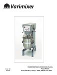
MIXER
AR 30 MK 1
Installation and Operation Manual
S/N: 35728
Rev.: 2.0
17.12.2004
Rev. 2.0
Dear Customer,
Congratulations on deciding to choose a Metos appliance for your kitchen activities. You
made an excellent choice. We will do our best to make you a satisfied Metos customer
like thousands of customers we have around the world.
Please read this manual carefully. You will learn correct, safe and efficient working methods in order to get the best possible benefit from the appliance. The instructions and hints
in this manual will give you a quick and easy start, and you will soon note how nice it is
to use the Metos equipment.
All rights are reserved for technical changes.
You will find the main technical data on the rating plate fixed to the equipment. When you
need service or technical help, please let us know the serial number shown on the rating
plate. This will make it easier to provide you with correct service.
For your convenience, space is provided below for you to record your local Metos service
contact information.
METOS TEAM
Metos service phone number:...............................................................................................
Contact person:....................................................................................................................
1
17.12.2004
2
Rev. 2.0
17.12.2004
Rev.
1. General .......................................................................................................... 1
1.1 Symbols used in the manual .......................................................................................... 1
1.2 Symbols used on the appliance ...................................................................................... 1
1.3 Checking the relationship of the appliance and the manual .......................................... 1
2. Safety .............................................................................................................. 3
2.1 Safety instructions in case of malfunction ..................................................................... 3
2.2 Disposal of the appliance ............................................................................................... 3
3. Functional description .................................................................................. 4
3.1 General .......................................................................................................................... 4
3.2 Intended use of the appliance ........................................................................................ 4
3.3 Construction of the mixer .............................................................................................. 4
4. Operation instructions ................................................................................. 5
4.1 Operation of the mixer ...................................................................................................
4.1.1 Recommended maximum speeds ...........................................................................
4.1.2 Procedure for starting after emergency stop ..........................................................
4.1.3 Overload .................................................................................................................
4.1.4 Maximum capacity of the mixer ............................................................................
4.1.5 Correct use of tools ................................................................................................
4.1.6 Recommended applications for tools .....................................................................
4.2 After use ........................................................................................................................
4.2.1 Cleaning ................................................................................................................
4.2.2 Maintenance and lubrication ..................................................................................
5
7
7
7
8
8
8
9
9
9
5. Installation ................................................................................................... 11
5.1 Preparing the installation .............................................................................................
5.2 Installation ...................................................................................................................
5.3 Electrical connections ..................................................................................................
5.4 Checking of the direction of rotation of the planetary head ........................................
11
11
11
11
6. Adjustment instructions ............................................................................. 12
6.1 Adjustment of special V-belt .......................................................................................
6.2 Adjustment of speed ....................................................................................................
6.3 Adjustment of bowl fixing ...........................................................................................
6.3.1 Adjustment of bowl centering ..............................................................................
6.3.2 Adjustment of bowl height ..................................................................................
12
13
13
14
14
1
17.12.2004
Rev.
7. Troubleshooting .......................................................................................... 16
8. Spare parts .................................................................................................. 17
8.1 Voltage codes .............................................................................................................. 19
8.2 Product codes ............................................................................................................... 19
9. Technical specifications .............................................................................. 59
2
17.12.2004
Rev. 2.0
General
1. General
Carefully read the instructions in this manual as they contain important information regarding proper, efficient and safe installation, use and maintenance of the appliance.
Keep this manual in a safe place for eventual use by other operators of the appliance.
The installation of this appliance must be carried out in accordance with the manufacturer’s instructions and following local regulations. The connection of the appliance to the
electric supply must be carried out by qualified persons only.
Persons using this appliance should be specifically trained in its operation.
Switch off the appliance in case of failure or malfunction. The periodical function checks
requested in the manual must be carried out according to the instructions. Have the appliance serviced by a technically qualified person authorized by the manufacturer and using
original spare parts.
Not complying with the above may put the safety of the appliance in danger.
The manufacturer does not take responsibility for any damages in case the operation instructions and warnings contained in this manual are neglected.
1.1
Symbols used in the manual
This symbol informs about a situation where a safety risk might be at hand. Given instructions are mandatory in order to prevent injury.
This symbol informs about the right way to perform in order to prevent bad results, appliance damage or hazardous situations.
This symbol informs about recommendations and hints that help to get the best performance out of the appliance.
1.2
Symbols used on the appliance
This symbol on a part informs about electrical terminals behind the part. The removal of
the part must be carried out by qualified persons only.
1.3
Checking the relationship of the appliance and the manual
The rating plate of the appliance indicates the serial number of the appliance. If the manuals are missing, it is possible to order new ones from the manufacturer or the local rep-
1
17.12.2004
Rev. 2.0
General
resentative. When ordering new manuals it is essential to quote the serial number shown
on the rating plate.
2
17.12.2004
Rev. 2.0
Safety
2. Safety
Putting your fingers in the bowl while the mixer is running may cause injuries.
2.1
Safety instructions in case of malfunction
Please take careful note of the following instructions and warnings:
2.2
Disposal of the appliance
Once the appliance has reached the end of its useful life, it must be disposed of in compliance with local rules and regulations. The appliance may contain substances/materials
which potentially have an adverse impact on the environment as well as recyclable materials. The best way of dealing with such substances is to dispose of them through a proper
waste company.
3
17.12.2004
Rev. 2.0
Functional description
3. Functional description
3.1
General
This appliance does not contain parts which can be serviced by the user. Maintenance
must be carried out by authorised personnel.
3.2
Intended use of the appliance
The appliance is intended for manufacture of products which do not during processing
cause reactions or emit substances which may be detrimental to the user
3.3
Construction of the mixer
/LIWORZHULQJ
RIERZO
0RWRUUHOD\
WKHUPDORYHU
ORDGUHOD\
6DIHW\VZLWFKIRUOLG
H[WUDHTXLSPHQW
6SHHG
DGMXVWPHQW
)XVH
6DIHW\VZLWFKIRU
VDIHW\JXDUG
0RWRU
6L]HRI
PL[HU
0RWRU
$5
NZ
$5
NZ
$53
NZ
$5
NZ
$53
NZ
6DIHW\VZLWFK
IRUERZOOLIW
4
17.12.2004
Rev. 2.0
Operation instructions
4. Operation instructions
4.1
Operation of the mixer
A Open the safety guard and place the bowl in the bowl arms. The bowl arms must be in
the lowest position and the bowl must be pushed all the way into the bowl arms (fig.2 or
fig.3).
B Place the mixing tool in the bayonet shaft. The pin on the tool must be turned into the
bayonet hole (fig.2).
C Raise the bowl to working position by turning the handle for bowl lift in the direction
of the arrow (fig.2).
)LJ
0L[HU ZLWK RSHQ
VDIHW\JXDUGORZ
HUHG ERZO DQG
PRXQWHGWRRO
)LJ
0L[HU VHHQ IURP
DERYH WKH ERZO KDV
EHHQ SXVKHG DOO WKH
ZD\LQWRWKHERZODUPV
1RWLFH WKH WKLUG
³HDU´ RI WKH ERZO LV
IDFLQJWKHPL[HU
)LUVW³HDU´
7KLUG
³HDU´
6HFRQG³HDU´
5
17.12.2004
Rev. 2.0
Operation instructions
D If the mixer is equipped with a timer, set the mixing time requred by turning the timer
(fig.1) clockwise. The mixer will stop automatically when the time runs out. When the
mixer has been stopped due to an end of timer, the ”procedure for starting after emergency
stop” is used before the mixer is restarted. Set the timer on HOLD when not used, as otherwise the mixer can not be started.
The mixer must only be started when the bowl is in working position and the safety guard
is closed.
&IG
7LPHU
H[WUDHTXLSPHQW
6WDUW
6WRS
(PHUJHQF\VWRS
H[WUDHTXLSPHQW
F Turn the speed selector lever (fig.4) to the rear until the required speed has been obtained.
The speed must be changed only when the mixer is running.
The mixer must not be started when loaded in high speed position.
G Before the mixer is stopped, the speed selector lever must be moved back to the lowest
speed (fig.4).
)LJ
0L[HUZLWKFORVHG
VDIHW\ JXDUG UDL
VHG ERZO DQG
PRXQWHGWRRO
6
17.12.2004
Rev. 2.0
Operation instructions
H Stop the mixer by pressing the red stop button 0.
4.1.1
Recommended maximum speeds
Please take note of the recommended maximum speeds below:
4.1.2
Procedure for starting after emergency stop
This procedure must be used in cases where the mixer has been stopped in high speed.
•
•
•
•
4.1.3
Lower the bowl and remove the tool from the bayonet.
Raise the bowl arms,either empty or with the bowl.
Close the safety guard, start the mixer and move the speed selector lever back to
the lowest speed.
Switch off the mixer. Now the mixer can be started as usual.
Overload
Do not overload the mixer. Sticky and heavy doughs may reduce the capacity of the bowl
by 75%. The capacity is further reduced if the speed of the mixing tool is increased beyond the recommended values or if a wrong mixing tool is used. Large lamps of fat or
cooled ingredients must be cut into small parts before they are placed in the bowl.
Prolong overload will make the mixer’s motor protection disconnect the mixer. Leave the
mixer for approx. 3 minutes and restart it again as described under “Procedure for starting
after emergency stop”.
7
17.12.2004
Rev. 2.0
Operation instructions
4.1.4
Maximum capacity of the mixer
6L]HRIPL[HUOLWUHV
$5
$5 $53 $5 $53
'RXJKZLWK
$5 NJ
NJ
NJ
NJ
NJ
DJLYHQ$5
$5 NJ
NJ
NJ
NJ
NJ
$5
$5 NJ
NJ
NJ
NJ
NJ
6L]HRIPL[HUOLWUHV
$5
(JJZKLWH
/ HJJV
$5 $53 $5 $53
/
:KLSSHGFUHDP
/
/
/
/
/
/
/
0D\RQQDLVH
/
/RLO
/
/
/
/
SURGXFWV 0DVKHGSRWDWRHV NJ
NJ
NJ
NJ
NJ
2WKHU
%LVFXLWERWWRP
/
/
'RXJK
/OLTXLG
6SRQJHFDNH
4.1.5
/
/
/
/
/
NJ
NJ
NJ
NJ
NJ
$5 $EVRUSWLRQ5DWLR$5
/LTXLGLQRIVROLGV
([DPSOH$EDVLFUHFLSHFRQWDLQVNJRIVROLGVDQG
NJRIOLTXLG
7KLVJLYHV$5 NJV[ NJV
,IIRULQVWDQFHLWLVUHTXLUHGWRXVHWKHPD[LPXPFD
SDFLW\RIWKHPL[HUWKHFDOFXODWHG$5 LVXVHG
IRUGHWHUPLQLQJWKHDPRXQWRIVROLGVDQGOLTXLGLQWKH
GRXJK
,ID/PL[HULVXVHGDQGDGRXJKZLWK$5 LV
WR EH NQHDGHG WKH PD[LPXP FDSDFLW\ LV NJV
1RZWKHZHLJKWRIVROLGVLQWKLVGRXJKLVFDOFXODWHG
6ROLGV
0D[FDSDFLW\[ NJV[ NJV
$5
:HLJKWRIOLTXLG NJVNJV NJV
Correct use of tools
The meat mincer must not be used for production of bread crumbs as this will cause unnecessary wear and tear on some mixer parts.
Whips should not be struck against hard objects as e.g. the edge of the bowl. This will
make the life of the tool shorter due to increasing deformity.
4.1.6
Recommended applications for tools
Whip
•
•
•
•
cream
egg whites
mayonnaise
and the like
Beater
•
•
•
•
•
8
cake dough
butter cream
waffle dough
minced meat
and the like
17.12.2004
Rev. 2.0
Operation instructions
Hook
•
•
•
bread dough
dark bread
and the like
For production of mashed potatoes the special wing whip should be used, not the standard
whip.
4.2
After use
4.2.1
Cleaning
The mixer should be cleaned daily or after use. The mixer should be cleaned with a soft
cloth and clean water. Sulphonated soaps should be used with caution as they destroy the
mixer’s lubricants.
Never use high pressure cleaning for the mixer.
Bowls and tools of aluminium must not be washed with strong alkaline detergents (pH not
bigger than 9.0).
Please note that the plastic safety guard can be damaged if exposed to high temperature
for a considerable period (Max. temperature 65°C).
After using the attachment drive, it should be wiped inside with a soft cloth.
4.2.2
Maintenance and lubrication
The infinitely variable gear must be lubricated regularly, i.e. a lubrication interval of approx. 60 hours of operation.
Lubrication of infinitely variable gear:
Use the grease gun delivered with the mixer.
Start the mixer and increase the speed to approx. 50%. Stop the mixer and open the lid on
the top of the mixer. On the top of each of the two pulley set shafts is a grease nipple (fig.5
point 1). Press grease through the grease nipples until the grease gun feels hard to press
or until grease comes out between the shaft and the pulleys.
The mixer must not be started until the screws which hold the lid are inserted.
Start the mixer and set the speed back to low speed.
Stop the mixer and fill the grease gun with new grease so that it is ready for next time.
9
17.12.2004
Rev. 2.0
Operation instructions
ILJ
Lubrication of other movable parts:
The movable parts of the bowl arms, the shaft and the lifting rod must also be lubricated
with oil. Remove the rear covering and lubricate the marked points with an oil can (fig.5
point 2).
Grease types:
Grease for the pulley set shafts: Castrol LMX
On repair of the planetary head: Grease the toothed wheel and the toothed rim with Castrol
Molub Alloy 936SF Heavy or Castrol Grippa 355, the needle bearings in the planetary
head must not be lubricated with this type of grease. Do not use any other type of grease
than the one stated here.
10
17.12.2004
Rev. 2.0
Installation
5. Installation
5.1
Preparing the installation
It should be checked that all loose parts are delivered with the mixer such as bowl, tools,
grease gun and rubber feet.
5.2
Installation
Never lift the mixer by the handle for speed adjustments or for bowl lift.
The mixer is placed directly on the floor. Foundation bolts in the floor are only necessary
under special conditions, e.g. on ships.
The mixer must be mounted with rubber feet, which neutralize both shaking and rusting.
Spacers can be inserted under the mixer’s feet, if the floor is not completely even.
5.3 Electrical connections
The electrical connections can only be carried out by a qualified electrician having the
necessary competence for the installation and service of electrical appliances.
The mixer is to be connected to power via a plug. The plug must be dimensioned for min.
16A, 230/400V~, IP44.
When connecting:
•
•
•
•
1 phase with N+earth, use 3 pole plug
2 phases+earth, use 3 pole plug
3 phases+earth, use 4 pole plug
3 phases with N+earth, use 5 pole plug
Before the mixer is connected to power, it should be checked that the voltage and frequency printed on the machine label is correct in relation to the place of installation. The machine label is placed at the top right side of the mixer.
5.4
Checking of the direction of rotation of the planetary head
Lift up the bowl arms to normal working position and start the mixer without bowl and
tools. Check the direction of rotation of the planetary head: the planetary head must rotate
in the direction as stated by the arrow above the planetary head. If the direction of rotation
is wrong, 2 of the phase wires of the connecting cable must be inverted.
11
17.12.2004
Rev. 2.0
Adjustment instructions
6. Adjustment instructions
Prior to a possible repair or adjustment, switch off the mixer by disconnecting the power
cable.
6.1
Adjustment of special V-belt
;
7
+
8
.
-
)
.
=
(
=
$
%
.
)
(
7
;
$5
$5
$5
PPPP
PPPP
PPPP
*
9
. -
- .
.
9
The distance (X) is only indicative as it depends on the tolerance of the special V-belt.
Start by tightening the V-belts (*)
Tighten the special V-belt (A) by moving one or two washers from (V) to (T).
Start the mixer and leave it running while the nut (U) is tightened. Do not tighten it too
much
12
17.12.2004
Rev. 2.0
Adjustment instructions
On the front pulley set the stud (E) on the varispeed collar (F) must be placed inside the
lower fork (G) and on the rear pulley set outside the fork for belt tightener (B), (both must
point backwards).
Tolerances in the transmission might cause that the special V-belt (A) is hitting the pins
of the pulley sets when the speed has been adjusted. In such cases the distance (X) must
be reduced.
Then follow the section ”Adjusment of speed”.
6.2 Adjustment of speed
The stop screws (J) on the speed lever should be adjusted so that the measurement (H) is
1-2 mm on the front and rear pulley, at low and high speed respectively. Tighten the counter nuts (K) when the speed is correctly adjusted.
6.3
Adjustment of bowl fixing
ILJ
$GMXVWLQJGLDPHWHU
The bowl arms must be raised to normal working position. Loosen the counter nuts (1)
and remove the cotterpins (2). Turn the bolts (3) until correct fixing of the bowl is
achieved. By turning the bolts out of the extension tube the fixing is increased. Start by
turning one of the bolts half a revolution.
13
17.12.2004
Rev. 2.0
Adjustment instructions
The adjusting diameter shall be measured inside between the bowl arms:
Adjusting diameter:
•
•
•
6.3.1
AR30 = 361,8mm
AR40 = 391,3mm
AR60 = 450,4mm
Adjustment of bowl centering
Loosen the counter nuts (1) and remove the cotterpins (2). Turn the bolts (3) until the bowl
is in the centre of the mixer. In order not to alter the fixing of the bowl, one of the bolts
must be turned out of the extension tube and the other into the extension tube. Use the flat
beater to check that the bowl is correctly centered and turn the planetary head with your
hand before the voltage is connected.
6.3.2
Adjustment of bowl height
The distance (X) is measured from the bottom side of the bayonet hole to the surface on
the bowl arms on which the bowl rests (fig.7a). The bowl arms must be lifted to normal
working position.
AR30 = 162mm
X:
AR40 = 162mm
AR60 = 178mm
ILJD
14
17.12.2004
Rev. 2.0
Adjustment instructions
Lower the bowl arms down on a wooden block so that the weight of the bowl arms are not
loading the lifting system. Loosen the counter nut (1), (fig.7b). Take out the cutter pin (2).
Take out the lifting rod (3). The lifting bolt (4) is now loose and can be turned out or into
the lifting nut (5), until the correct height of the bowl arms has been reached.
ILJE
15
17.12.2004
Rev. 2.0
Troubleshooting
7. Troubleshooting
If the appliance fails to work, check to ensure that
•
•
•
•
it has been used according to instructions
all removable parts are in place
the disconnection switch (usually on a wall or in the immediate vicinity of the appliance) is in the ON position
the fuses (overload protections) have not blown on the fuse board. Ask a qualified
person to check the overload protections.
PROBLEM
MEASURES
A rattling sound from the closed part of the mixer
The mixer starts striking when kneading dough which
normally causes no problems
The mixer changes its speed by itself
The minimum and the maximum speeds are changing
The bowl is too tight or too loose
The tool hits the sides of the bowl
The tool hits the bottom of the bowl
Adjustment of special V-belt
Adjustment of special V-belt
Adjustment of special V-belt
Adjustment of speed
Adjustment of bowl fixing
Adjustment of bowl centering
Adjustment of bowl height
When you contact service personnel, give the following information about the unit in
question:
•
•
•
•
16
the type and model of the unit
the serial number of the unit and the date the unit has been installed
a short description of the fault, what function is not working, what signals the displays are showing
what happened/was done immediately before the fault occurred
17.12.2004
Rev. 2.0
Spare parts
8. Spare parts
Speed regulation ................................... 21
Transmission......................................... 23
Planetary head ...................................... 27
Machine column ................................... 31
Safety guard .......................................... 35
Safety guard, removable ...................... 39
Attachment drive.................................. 47
Microswitches ....................................... 51
Electric components ............................. 53
Bowls and mixing tools ........................ 57
17
17.12.2004
Spare parts
18
Rev. 2.0
17.12.2004
Rev. 2.0
Spare parts
Voltage
Voltage code
A
3/N/PE∼400/230V 50Hz
B
∼250V 16A 50Hz
C
3/N/PE∼380/220V 50Hz
D
3/PE∼200V 50-60Hz
F
2/PE 220−240V 50Hz
G
3/N/PE∼415/240V 50Hz
H
3/PE∼230V 50Hz
I
3/PE∼220V 60Hz
J
3/PE∼380 50Hz
K
3/PE∼400V 50Hz
L
3/PE∼415V 50Hz
M
3/PE∼440V 60Hz
N
3/PE∼460V 60Hz
O
3/PE∼480V 60Hz
P
1/N/PE~220-240V 50Hz
R
2/PE~220-230V 60Hz
S
3/N/PE∼400/230V 50Hz
T
3/PE∼230V 60Hz
U
1/N/PE~100V 50-60Hz
Product code
8.1
Voltage codes
8.2
Product codes
Full name
Model codes
30
Mixer AR 30
19
17.12.2004
Rev. 2.0
Spare parts
20
17.12.2004
Rev. 2.0
Spare parts
ID
Code
Model Description
Module:Speed regulation
10
AR31-47Z
Speed selector lever,assy
20
AR30-47.10
Disc with arrow
30
AR30-47.11
Clamp
40
STA3306
Knob Ø 40, black
50
STA3414
Circlip 30U
60
STA5247
Screw 8x13
70
STA5439
Screw M8x60
80
STA5810
Nut M8
30=AR 30
21
17.12.2004
Rev. 2.0
Spare parts
22
17.12.2004
Rev. 2.0
Spare parts
ID
Code
Model Description
Module:Transmission
90
STA6018
Washer 40x13x3
100
R15-13.1
Pulley assy
110
R30-285
Pin
120
R15-103
Ball bearing f/15 6010 2RS1
130
R15-15Z
Pulley movable, assy
140
STA2505
Bearing bush MB0610DU
150
R27-128
Standard v-belt pulley
160
R15-41Z
Bearing shaft
170
STA2024
Tight fitting key A 6x6x28
180
STA3220
Grease nipple
190
STA3410
Circlip 25U
200
6205 2RS
Ball bearing 6205 2RS.1-C3
210
STA3514
Circlip 52l
220
R15-17.1
Varispeed collar
230
R15-143
Distance tube
240
R30-60
Arm for bearing
250
STA5348
Screw M10x55
260
STA6010
Washer 10.5x20x2.0
270
R27-91
Special v-belt
280
R15-156
Thread nipple
290
R15-13.1Z
Pulley assy
300
STA6018
Washer 37x13x3
310
R15-59Z
Motor pulley shaft assy
320
STA5602
Screw M5x10
220
R15-17.1
Varispeed collar
330
R27-227Z
Clamping ring compl.
340
STA2011
Key A5x5x57
350
R15-18Z
Bearing bracket assy
30=AR 30
23
17.12.2004
Rev. 2.0
Spare parts
24
17.12.2004
Rev. 2.0
Spare parts
ID
Code
Model Description
Module:Transmission
360
STA5014
Slotted screw M8x16 DIN963
370
STA5612
Screw M5x20
380
R60-61.1
Base for motor
80
STA5810
Nut M8
390
STA5895
Flanged nut M8 DIN6923 FZB
400
AR31-305
Pin bolt
410
R20-26.1
Support bracket for belt tightener
420
STA5444
Screw M8x80 DIN933 8.8 FBZ
430
STA5345
Screw M10x30
440
R27-16
Lower fork
450
R20-19
Fork for the belt tightener
460
R20-275
Spring f/tightening the v-belt
470
R15-46Z
Toothed rack assy
480
STA5815
Nut M16
490
STA3407
Circlip 19U
500
STA6040
Washer
510
STA5433
Screw M8x25
520
STA6026
Washer 20x10x2,5
530
R15-142
Grease gun
540
R20-249
Label "greased for life"
30=AR 30
25
17.12.2004
Rev. 2.0
Spare parts
26
17.12.2004
Rev. 2.0
Spare parts
ID
Code
Model Description
Module:Planetary head
550
R30-1
Gear wheel rim
560
R30-2Z
Eccentric head
570
R40-3Z
Main bearing mounted
580
STA3526
Circlip 80L
590
R30-101Z
Needle bearing compl. BK2518 RS
600
R30-30Z
Main shaft assy
610
R30-31
Rim pinion
620
R30-32
Rim pinion, lower
630
R30-33Z
Bayonet shaft compl.
640
R30-36Z
Eccentric disc mounted
650
R30-37
Distance piece
660
R30-96
Needle bearing f/33Ø, HK 2820
670
R30-97
Ball bearing f/33n, 6207 2RS1C
680
R30-98
Ball bearing f/30
690
R30-99
Ball bearing f/30
700
R40-34
Distance piece
710
R15-109
Spring f/33
720
R30-100
Ball bearing f/30m, 6008 2RS1C
730
R30-106
Ball 5/6s.s.
740
R40-141
Distance piece
750
STA2030
Key B8x7x20
760
STA2038
Key A8x7x67
770
AR30-162H
Plastic cap, white
780
W30-209
Rubber ring f/33
790
W30-272
Headcap
800
W30-272.1
Headcap ss f. scraper
810
STA5640
Screw M8x50
820
STA5641
Screw M8x80
30=AR 30
27
17.12.2004
Rev. 2.0
Spare parts
28
17.12.2004
Rev. 2.0
Spare parts
ID
Code
Model Description
Module:Planetary head
830
STA6043
Washer 40x50x0.5
840
STA6046
Washer
850
STA6055
Lockwasher 8mm
860
STA6057
Lockwasher 10mm
870
STA6460
Groove pin Ø8x24
880
STA3425
Circlip 40UC
890
STA3472
Circlip SW22
900
STA3520
Circlip 68L
910
STA3522
Circlip 72L
920
STA5044
Screw M4x16 counters. DIN965A
930
STA5346
Screw M10x40
940
R40-129
V-belt pulley 50Hz
950
R40-129A
V-belt pulley 60Hz
960
R40-90
Standard v-belt A27 50Hz
970
R40-90.1
Standard v-belt A29 60Hz
30=AR 30
29
17.12.2004
Rev. 2.0
Spare parts
30
17.12.2004
Rev. 2.0
Spare parts
ID
Code
Model Description
Module:Machine column
980
R15-245
Arrow
990
STA3002
Cable inlet compl. PG13.5
1000
STA6580
Threaded bush
1010
AR30-212
Knee, plug button
1020
AR30-213
Foot
1030
AR31-163
Closing plate UL-hole
1040
STA3411
Clamping ring KS 6
1050
AR31-22MO
Machine column, white
1060
STA2515
Bearing bush MB2030DU
1070
STA2520
Bearing bush MB2525DU
1080
AR30-214.3
Intermediate piece 3mm
1090
AR30-214.6
Intermediate piece 6mm
1100
STA3014
Nut PG 13.5
1110
STA5017
Screw M6x20
1120
STA5080
Screw s.s. M6x10
1130
STA5232
Earth screw RX-TT M4x8 mm
1140
AR31-22.17R
Cover plate 30/40 L stainless
1150
AR31-21
Topcover set, stainless steel
1160
AR31-306
Stopper
1170
R15-244
Machine number sign
1180
STA6510
Plug button ø88.9
1190
AR31-270
Cover plate NSF, upper
1200
AR31-271
Cover plate NSF, lower
1210
STA5834
Lock nut M5
1220
STA6027
Washer 18x6.4x1.6mm
1230
AR31-148M4
Tie rod for motor bracket
1240
STA5625
Screw M8x25
1250
STA6056
Lockwasher 8mm
30=AR 30
31
17.12.2004
Rev. 2.0
Spare parts
32
17.12.2004
Rev. 2.0
Spare parts
ID
Code
Model Description
Module:Machine column
1260
R30-70.1
Rollpin
30=AR 30
33
17.12.2004
Rev. 2.0
Spare parts
34
17.12.2004
Rev. 2.0
Spare parts
ID
Code
Model Description
Module:Safety guard
1270
00001-14030-001
Safety guard AR30 compl.grid
1280
00001-14030-002
Safety guard compl.plast AR30
1290
STA3307
Knob Ø 32, black
1250
STA6056
Lockwasher 8mm
1300
56G30-21
Grid front part AR30
1310
56G20-280
Detachable filling skid for safety guard
1320
56G30-22
Grid rear part AR30
1330
56P30-75
Fittings for safety guard
1340
STA5665
Screw M6x16
1350
56P30-15
Fittings for microswitch compl.
1360
STA5251
Plate screw 4x16 DIN7981
1370
56SN30-13
Fitting for microswitch
1380
56SN20-30
Microswitch
1390
STA5819
Nut M6
1400
STA5250
Screw M6x50
1410
AR30-193M
Cable for microswitch
1420
56SN30-22
Cam disc
1430
56SN30-21
Bearing for safety guard
1440
56SN30-24
Distance washer
1450
56SN30-23
Lock washer
1460
56G30-26
Nut M8 special
80
STA5810
Nut M8
1470
STA5093
Screw M8x30, stainless steel
1480
STA5321
Screw M5x16
1490
STA5838
Nut M5
1500
STA5842
Lock nut M8
1510
STA6003
Washer, safety guard
1520
56P30Z/56P30.1Z
AR30 safety guard/front+rear plast AR30
30=AR 30
35
17.12.2004
Rev. 2.0
Spare parts
36
17.12.2004
Rev. 2.0
Spare parts
ID
Code
Model Description
Module:Safety guard
1530
56P30-34
Clamp for safety guard AR30-40
1540
56P30-35
Threaded plate
30=AR 30
37
17.12.2004
Rev. 2.0
Spare parts
38
17.12.2004
Rev. 2.0
Spare parts
ID
Code
Model Description
Module:Safety guard, removable
1550
00001-14030-501
Removable safety guard complete, grid
1560
00001-14030-502
Removable safety guard complete, plast
1290
STA3307
Knob Ø 32, black
1570
STA5005
Slotted screw st.acidres. M5x35 DIN963
1580
STA5013
Screw M6x30 s.s.
1590
STA5026
Slotted screw st. acidres M5x16 DIN963
1600
STA5831
Lock nut M6
1210
STA5834
Lock nut M5
1220
STA6027
Washer 18x6.4x1.6mm
1610
56AG30-21
Front part removable grid
1620
56AG30-22
Grid rear part, removable 30
1110
STA5011
Screw M6x20
1630
STA5607
Screw M6x6 s.s.
1640
56RN20-22
Cam disc, drilled
1650
56AR30-123Z
Shaft for cam disc
1660
56AR30-100.1
Supporting piece for AR30/40L
1650
56AR30-123Z
Shaft for cam disc
1650
56AR30-123Z
Shaft for cam disc
1670
56RN20-100.1M
Parcial mounting, left susp.
1360
STA5251
Plate screw 4x16 DIN7981
1680
56RN20-110.1
Back plate, left,machined
1380
56SN20-30
Microswitch
1410
AR30-193M
Cable for microswitch
1690
56RN20-124
Disc for hole, column
1700
STA5011
Screw M6x20
1590
STA5026
Slotted screw st.acidres. M5x16 DIN963
1710
56AR30-101.1
Retaining piece,right 30/40L
1720
56RN20-101.1M
Partial mounting, right susp.
30=AR 30
39
17.12.2004
Rev. 2.0
Spare parts
40
17.12.2004
Rev. 2.0
Spare parts
ID
Code
Model Description
Module:Safety guard, removable
1730
56AP30-109
Fittings for rear part comp.30
1740
56AP30-2
Rear part,rem. safety guard
1750
56AP30-206
Bottom fittings for rem.pl.30
1530
56AP30-34
Clamp for safety guard AR30-40 rem.
1760
56P30-13
Front part, plast AR30
1540
56P30-35
Threaded plate
1770
STA5314
Set screw, acid.res.M8x14H DIN933
1480
STA5321
Screw M5x16
1490
STA5838
Nut M5
1780
STA6152
Nord-lock disc,acid.res.M8
1790
56G20-280
Detachable filling skid f.safety guard,grid
30=AR 30
41
17.12.2004
Rev. 2.0
Spare parts
42
17.12.2004
Rev. 2.0
Spare parts
ID
Code
Model Description
Module: Lifting system
1800
R15-65
Lifting nut
1810
R30-69Z
Extension tube
1810
R30-69Z
Extension tube
1820
AR31-67
Lifting pin
1830
R27-62Z
Lifting lever assy
1840
STA3308
Knob ø40 red
1850
STA2020
Key B6x6x15
490
STA3407
Circlip 19U
1860
R27-63Z
Crank shaft compl.
1870
R27-83Z
Lifting bolt
1880
STA5827
Nut M12
1890
STA3580
Circlip ST 10
1900
STA5088
Screw M8x16 stainless steel
1910
AR31-128
Roll for bowl clamping
1920
AR31-68Z
Bowl arm guide rod compl.
1930
STA3467
Circlip AS25
1940
AR31-23/24Z
Bowl arm set compl.w/rollers
1950
STA2522
Bearing bush MB2550DU
30=AR 30
43
17.12.2004
Rev. 2.0
Spare parts
44
17.12.2004
Rev. 2.0
Spare parts
ID
Code
Model Description
Module:Lifting system
1960
AR31-127
Roller shaft
1970
STA5690
Fitted bolt M8x25
1880
STA5827
Nut M12
1980
STA6044
Washer 20x28xx0.5
1990
STA6205
Cotter pin
2000
W40-600M
Oil damper mounted
30=AR 30
45
17.12.2004
Rev. 2.0
Spare parts
46
17.12.2004
Rev. 2.0
Spare parts
ID
Code
Model Description
Module:Attachment drive
2010
R15-5
Bearing hub
2020
R20-9
Worm wheel
2030
R15-10
Gear case
2040
R15-11
Gear case cover
2050
R20-49
Worm
2060
R20-52Z
Gear shaft assy
2070
R15-50Z
Attachment drive shaft assy
2080
STA2032
Key A8x7x42.5
2090
R20-104
Ball bearing f/52 6205 2RS1C3
2100
R20-107
Oil seal f/50 254710
2110
R20-300
Gasket for R15-10
2120
R20-300Z
Gasket for R15-10
2130
R20-301
Gasket for R15-10
2140
STA2007
Key A5x5x25
340
STA2011
Key A5x5x57
190
STA3410
Circlip 25U
2150
STA5018
Screw M8x20
2160
6005 2RS
Ball bearing
510
STA5433
Screw M8x25
2170
STA5908
Seal washer ø8
2180
STA6020
Washer 5/16"x3/4" elzinkt
2190
STA6054
Washer
1250
STA6056
Lockwasher 8mm
2200
R15-211
Rubber ring f/8
2210
R15-214
End cover
2220
R15-8MO
Attachm.engagement hub white
2230
STA5322
Screw M8x20
2240
STA5561
Finger screw
30=AR 30
47
17.12.2004
Rev. 2.0
Spare parts
48
17.12.2004
Rev. 2.0
Spare parts
ID
Code
Model Description
Module:Attachment drive
1250
STA6056
Lockwasher 8mm
2250
STA6316
Roll pin ø8x20
2260
Motor complete without attach. drive
2270
Motor complete with attach. drive
30=AR 30
49
17.12.2004
Rev. 2.0
Spare parts
50
17.12.2004
Rev. 2.0
Spare parts
ID
Code
Model Description
Module:Microswitches
2280
AR140-173
Microswitch "CE" for bowllift
2290
AR31-194.11
"GS" microswitch cable mounted
2300
R27-172
Microswitch
2310
AR61-194.12
Cable for lid microswitch
2320
STA5662
Screw M3x20
2330
AR30-250
Distance piece
2340
STA5126
Screw M3x50
2350
STA5817
Nut M3
2360
STA6024
Washer 3x10
30=AR 30
51
17.12.2004
Rev. 2.0
Spare parts
52
17.12.2004
Rev. 2.0
Spare parts
ID
Code
Model Description
Module:Electric components
2370
STA3000
Cable inlet PG11
2380
STA3010
Nut PG11
2390
AR31-194.8M
Main circuit cable AR31-AR101
2400
AR30-453
Earth mark, adhesive 9x13
2410
AR31-149
Front panel, punched
2420
AR31-149.5
Front foil, standard
2430
AR31-152Z
Cover box, elec
2440
AR31-457
Earth clamp
2450
STA5897
Flanged nut M5 DIN6923 FZB
2460
STA6483
Press screw CH-M5x15
2470
STA3017
Cable inlet,nylon PG11
2480
STA5097
Stainless mixer screw galv. black M6x10
1130
STA5232
Screw M4x8
2490
RN30-194.9M
Cable 4x1.5 white
2500
RN30-194.10M
Cable 3x1.5 white
2510
AR31-174.2
Start switch complete
2520
AR31-174.3
Stop switch complete
2530
R20-88.002,(........)
Contactor CI4-5 220V 50/60
2540
R20-88.011,(........)
Thermal release TI9 2.7-4
2550
R20E-416.1
Fuse holder compl.
2560
R20E-418.3
Fuse 1A, slow 6.3x32 UL CSA
2570
AR30-188.1Z
Timer Compl. 30min. Mechanic
2580
W30-188.16Z
Timer Compl. 220V 60Hz 15min
2590
W30-188.17Z
Timer compl. 220V 50Hz 18min
2600
AR31-187.15
Timer dial 15 min
2610
AR31-187.18
Timer dial 18 min
2620
AR31-187.30
Timer dial 30 min
1130
STA5232
Screw RX-TT M4x8 mm
30=AR 30
53
17.12.2004
Rev. 2.0
Spare parts
54
17.12.2004
Rev. 2.0
Spare parts
ID
Code
Model Description
Module:Electric components
2630
W30-189
Knob for electric timer
2640
AR31-149.1
Front plate, emergency stop
2650
AR31-174.5
Emergency stop compl.
2660
R30-85.1;R40-85.1(85.30)
Motor
2670
RN30-194.1M
Cable 5x1.5 white
2680
RN30-194.2M
Cable 4x1.5 white
2690
RN30-194.3M
Cable 3x1.5 white
30=AR 30
55
17.12.2004
Rev. 2.0
Spare parts
56
17.12.2004
Rev. 2.0
Spare parts
ID
Code
Model Description
Module:Bowls and mixing tools
2700
RN30-75M
30L bowl stainless steel
2710
RN30-75.1M
30L bowl st.steel acidproof 316
2720
RN30-75AM
30/15L bowl stainless steel
2730
RN30-75A1M
30/15L bowl stainless steel acidproof
2740
RN30-78M
30L hook,stainless steel
2750
R27-78AM
30/15L hook,stainless steel with pin p
2760
RN30-27M
30L flat beater
2770
R27-27AM
30/15L flat beater
2780
RN30-27.2M
30L flat beater, st.steel
2790
RN30-27.1M
30L flat beater, acidproof st.steel
2800
R27-27A2M
30/15L flat beater,st.steel
2810
R27-27A3M
30/15L flat beater,st.steel, acidproof
2820
RN30-28M
30L whip
2830
RN30-28MT
30L whip with thin wires
2840
R27-28AM
30/15L whip
2850
14RN30
30L wing whip, stainless steel
2860
14R30A
30/15L wing whip, st. steel
2870
39RN30
30L powder mixer, st.steel
2880
42RN30
30L scraper with nylon and holder
2890
42RN30T
30L scraper with teflon and holder
2900
42RN30A
30/15L scraper with nylon and holder
2910
42RN30AT
30/15L scraper with teflon and holder
2920
48R20Z
Rack for mixing tools
2930
48R60Z
Rack for mixing tools
2940
22AR30
Bowl truck compl. for AR30+R30/15L
2950
22AR30A
AR30/15 bowl truck compl.
30=AR 30
57
17.12.2004
Spare parts
58
Rev. 2.0
17.12.2004
Rev. 2.0
Technical specifications
9.
Technical specifications
Wiring diagram: electrical.connection: 3ph.+N+E.
Ctrl.volt. to relay:1ph.+N
Wiring diagram: electrical connection:3ph.+E.Ctrl. volt.to
relay: 2 phases
Wiring diagram: electrical connection:1ph.+N+E.or
2ph.+E.Ctrl.volt.to relay:1ph.+N or 2phases
Installation drawing A31-22.24
59
Wiring diagram: electrical connection: 3ph.+N+E. Ctrl.volt. to relay:1ph.+N
Wiring diagram: electrical connection:3ph.+E.Ctrl. volt.to relay: 2 phases
Wiring d-m:electrical connection:1ph.+N+E.or 2ph.+E.Ctrl.volt.to relay:1ph.+N or 2ph
17.12.2004
Rev. 2.0
Technical specifications
1
2#
3*
4*
5*
Safety switch for bowl lift
Safety switch for safety guard
Safety switch for lid
Timer
Emergency stop
* will only be mounted on request
# optional outside the EU
63
! 2 Installation drawing A31-22.24
17.12.2004
Rev. 2.0
Technical specifications
Item
Model
Specification
Capacity
30L
Motor
I kw
30=AR 30
65