1
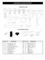
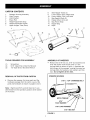
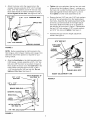
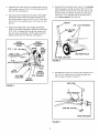
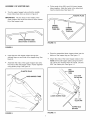
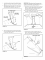
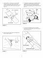
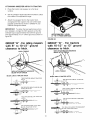
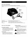
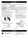
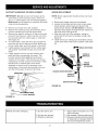
Owner's Manual
CRAFTSMAN
+
32" LAWNSWEEPER
Model No. 486.241322
CAUTION:
Before using this product, read
this manual and follow all
Safety Rules and
Operating
Instructions.
IMPORTANT
•
•
•
•
•
- READ THIS FIRST!!!
For Missing Parts or Assembly
Please Call 217-728-8388
Questions
Mon.-Fri. 7 am - 5 pm CST.
FAX 217-728-2032
or e-mail [email protected]
Missing parts will be sent UPS in 24 hours directly
Sears,
Roebuck
and Co., Hoffman
Estates,
Safety
Assembly
Operation
Maintenance
Parts
to your home.
IL 60179 U.S.A.
www.sears.com/craftsman
PRINTED
IN U.S.A.
FORM
NO.
48441
(REV.
5/02)
SAFETY RULES ........................................................
2
FULL SIZE HARDWARE CHART ............................. 3
CARTON CONTENTS ............................................... 4
ASSEMBLY ................................................................
4
OPERATION ............................................................
11
MAINTENANCE .......................................................
12
LIMITED ONE YEAR WARRANTY
SERVICE AND ADJUSTMENTS
............................
STORAG E ................................................................
TROUBLESHOOTING
.............................................
REPAIR PARTS ILLUSTRATION ..........................
REPAIR PARTS LIST ..............................................
PARTS ORDERING/SERVICE
ON CRAFTSMAN
13
13
13
14
15
................. Back Page
LAWNSWEEPER
For one year from the date of purchase, when this Lawnsweeper is maintained and lubricated according to the
operating and maintenance
instructions in the owner's manual, Sears will repair any defect in material or
workmanship free of charge, tf this Lawnsweeper is used for commercial or rental purposes, this warranty applies
for only 90 days from the date of purchase.
This warranty does not cover repairs necessary because of operator negligence or abuse, including the failure to
maintain the equipment according to instructions contained in the owner's manual.
WARRANTY SERVICE IS AVAILABLE
MENT IN THE UNITED STATES.
This warranty
BY CONTACTING
THE NEAREST
SEARS SERVICE CENTER/DEPART-
applies only while this product is in the United States.
This warranty gives you specific legal rights, and you may also have other rights which vary from state to state.
Sears, Roebuck and Co. D/817 WA. Hoffman Estates, Chicago, IL 60179
Any power equipment can cause injury if operated improperly or if the user does not understand
the equipment. Exercise caution at all times, when using power equipment.
•
•
•
•
•
Read the vehicle and sweeper owners manuals and
know how to operate your vehicle and sweeper
before using this sweeper attachment. Always
instruct other users before they operate the sweeper.
Do not permit children to operate sweeper.
Do not permit anyone to ride on sweeper.
Never attach the hopper rope to any part of your
body or clothing! Never hold onto the rope while
towing the sweeper! Attach the rope to the towing
vehicle to keep it away from wheels and rotating
parts.
Operate the sweeper at reduced speed on rough
terrain, near ditches and on hillsides to prevent loss
of control.
Look for this symbol to point out important
Become alert!! Your safety is involved.
The model number and serial numbers will be found on
a decal attached to the sweeper housing.
You should record both the serial number and the date of
purchase and keep in a safe place for future reference.
•
•
•
•
•
how to operate
Vehicle braking and stability may be affected with the
attachment of this sweeper. Do not fill sweeper to
maximum capacity without checking the capability of
the towing vehicle to safely pull and stop with the
sweeper attached. Stay off of steep slopes.
Stop and inspect vehicle and sweeper for damage
after striking an object. Repair any damage before
continuing operation.
Keep sweeper away from fire. Excessive heat can
damage the brushes and hopper bag and could
cause the bag and its contents to burn.
Before storing the sweeper, always empty the hopper
bag to avoid spontaneous combustion.
Follow maintenance and lubrication instructions as
outlined in the maintenance section of this manual.
safety precautions.
It mean--Attention!!
MODEL NUMBER:
SERIAL NUMBER:
DATE OF PURCHASE:
486.241322
SHOWN
FULL SIZE
©] fO
(_]Jp
NOT SHOWN
_/Q
FULL SIZE
_u
W
REF.
A
B
C
D
E
F
G
H
I
J
K
L
QTY.
DESCRIPTION
REF.
1
5
1
3
1
6
3
1
3
1
1
2
Hex Bolt, 3/8" x 1-1/2"
Hex Bolt, 3/8" x 3/4"
Hex Bolt, 5/16" x 3/4"
Carriage Bolt, 5/16" x 3/4"
Truss Head Bolt, 5/16" x 3/4"
Hex Lock Nut, 3/8"
Hex Lock Nut, 5/16"
Hex Nut, 5/16"
Washer, 5/16"
Lock Washer, 5/16"
Pivot Bushing
Hitch Spacer
M
N
O
P
Q
R
S
T
U
V
W
X
QTY.
6
1
2
2
2
3
1
1
1
1
1
2
DESCRIPTION
Hair Cotter Pin, 3/32"
Hair Cotter Pin, 1/8"
Clevis Pin, 1/4" x 1-1/8"
Clevis Pin, 3/8" x 3"
Clevis Pin, 3/8" x 1/2"
Plastic Plug, 1/4"
Grip
Knob, Plastic
Hitch Pin
Brace Rod Clip
Angle Bracket
Bag Retainer
CARTON
1.
2.
3.
4.
5.
6.
7.
CONTENTS
8.
9.
10.
11.
12.
13.
14.
15.
Sweeper Housing Assembly
Hitch Tongue
Hitch Bracket
Brace Rod
Height Adjustment Strap
Height Adjustment Handle
Upper Hopper Tube (Rear)
Side Hopper Tubes (2)
Lower Hopper Tube, Right Hand
Lower Hopper Tube, Left Hand
Bag Support Rods (2)
Hopper Mount Arms (2)
Bag Frame Strap
Hopper Bag
Rope
4
/
/
TOOLS
(1)
(2)
(2)
REQUIRED
Screwdriver
9/16" Open End or Box End Wrench
1/2" Open End or Box End Wrench
REMOVAL
•
FOR ASSEMBLY
OF PARTS
FROM
CARTON
ASSEMBLY
•
3
OF SWEEPER
Remove the 5/16" hex nut, 5/16" lock washers
5/16" flat washer from the two 5/16" x 1-3/4"
and
carriage bolts as shown in figure 1. Assemble the
hitch tongue to the sweeper, reusing the same two
carriage bolts, flat washers, lock washers and hex
nuts. Do not tighten at this time.
SWEEPER HOUSING
Remove the sweeper, the loose parts and the
hardware package from the carton. Lay out the
parts and hardware as shown on pages 3 and 4.
5/16" x 1-314" CARRIAGE BOLT
Note:
Right hand (R.H.) and left hand (L.H.) are
determined from the operators position while seated
on the tractor.
HITCH TONGUE
5116"
FLAT WASHER
5/16" LOCK WASHER
5/16" HEX NUT
FIGURE 1
Attach the brace rod to the square hole in the
sweeper housing using two 5/16"x 3/4" carriage
bolts, 5/16" flat washers and 5/16" hex lock nuts.
Place bolts heads on inside of sweeper housing.
Do not tighten at this time. See figures 2 and 3.
5/16"' HEX
LOCK
NUT
5/16"
x 3/4"
CARRIAGE
BOLT
BRACE ROD
Tighten (do not overtighten) the two hex nuts used
to secure the hitch tongue in figure 1, making sure
the brace rod is under the brace rod clip and pulled
back tight against the bolt. See figure 1,2 and 3.
Now tighten all other bolts assembled so far.
Remove the two 5/16" hex nuts, 5/16" lock washers
and 5/16" curved washers from the height adjustment tube. Assemble the height adjustment handle
to the two curved head bolts in the height adjustment tube. Slide the handle as far as possible in
the direction of the arrows in figure 4. Reassemble
the two 5/16" lock washers, 5/16" curved washers
and 5/16" hex nuts and tighten. See figure 4.
Assemble the grip onto the height adjustment
handle. See figure 4.
5116" HEX NUT
5/16"
FLAT WASHER
GRIP
SWEEPER
HOUSING
FIGURE 2
NOTE: Before assembling the hitch bracket to the
hitch tongue, refer to figure 3 below and to page 10 to
determine which hitch position is required for your
towing vehicle.
_16"
WASHER
CURVED
WASHER
Align the front holes in the hitch bracket and the
hitch tongue. Loosely assemble a 3/8" x 3/4" hex
bolt and a 3/8" hex lock nut as shown in figure 3.
Next, fasten the brace rod to the back hole in the
hitch bracket using the brace rod clip, a 3/8" x
1-1/2" hex bolt and a 3/8" hex lock nut. Do not
tighten
HEIGHT
ADJUSTMENT
HANDLE
CURVED
at this time. See figure 3.
HEIGHT
HITCH POSITION "'B'"
SEE PAGE 10
3/8"' x 3/4"
HEX BOLT
FIGURE 4
HEXx BOLT
3/8"
1-1/2"
= _)
BRACE ROD CLIP -
--F_L_
_,
BACK
"_'_
SWEEPER
HOUS,NG
HOLEjJ,$
BRACE ROD_
HITCH
-= - -________t
3/8"
HEX LOCK NUTS _
FIGURE 3
=
ADJUSTMENT
TUBE
HEAD
BO_
Assemble the two bag mount arms to the outside
of the sweeper housing using four 3/8" x 3/4" hex
bolts and 3/8" hex lock nuts. Use rear hole of dual
Assemble the short end of the angle bracket to the
hitch tongue using a 5/16" x 3/4" hex bolt and 5/16"
hex lock nut. See figure 5.
position holes in sweeper housing to install bag
mount arm. The notched side of the bag mount
arms faces upward. See figure 6.
Place the pivot bushing into the hole in the height
adjustment strap. Attach the strap and spacer to
the angle bracket using the 5/16" x 3/4" truss head
bolt, a 5/16" lock washer and a 5/16" hex nut. See
figure 5.
NOTCH
3/8" x 3/4" HEX BOLT
Attach the slotted end of the height adjustment
strap to the height adjustment handle by inserting a
5/16" x 3/4" carriage bolt through the handle and
then the strap. Assemble a 5/16" washer and the
plastic hand knob onto the bolt. See figure 5.
HEIGHT
ADJUSTMENT
STRAP
_
5/16"
x 3/4"
BAG MOUNT
ARM
HEIGHT
ADJUSTMENT
HANDLE
5116"
TRUSS
HEAD
BOLT
HEX BO
5/16" x 3/4"
CARRIAGE BOLT
USE REAR HOLE
3_"HEX
LOCK NUT
FIGURE6
5J
LOCK
5116"
HEX NUT
5116" HEX
LOCK NUT
PIVOT
BUSHING
5116" WASHER
•
Assemble the hitch pin, the two hitch spacers and
the 1/8" hair cotter pin to the hitch bracket and
hitch tongue as shown in figure 7.
ANGLE
BRACKET
HITCH PIN
FIGURE 5
t
HAIR PIN COTTER.....,_,_ I
HITCH SPACERS
FIGURE 7
ASSEMBLY
•
OF HOPPER
BAG
•
Fit the ends of the (RH) and (LH) lower hopper
tubes together. Align the holes in the tubes and
insert a plastic plug. See figure 10.
Turn the upper hopper tube so that the middle
brace holes face down as shown in figure 8.
PLASTIC PLUG
IMPORTANT:
The two holes in the middle of the
upper hopper tube must face down to allow assembly of the support rods.
/
LOWER
HOPPER
TUBE (RH)
T
LOWER
HOPPER
\
UPPER HOPPER TUBE
(brace holes on bottom)
FIGURE 10
FIGURE 8
Place the assembled lower hopper tubes into the
bottom of the hopper bag as. See figure 11.
Insert the two side hopper tubes through the
stitched flaps on each side of the hopper bag. See
figure 9.
Attach the ends of the lower hopper tubes to the
inside of the side hopper tubes using two 3/8" x
1/2" clevis pins inserted from the inside, and two
3/32" hair cotter pins. See figure 11.
Assemble the ends of the upper hopper tube onto
the ends of the side hopper tubes. Fasten together
using plastic plugs. See figure 9.
SIDE
_ PLASTIC PLUG
\\
HOPPER
TUBE
3/32" HAIR
COTTER PIN
SIDE HOPPER TUBE
P
i
LOWER HOPPER TUBE
3/8" x 112"
CLEVIS PIN
HOPPER BAG
BOTTOM
FIGURE 11
FIGURE 9
7
Insertthe bagframestrapintothestitchedsleeve
alongthe frontedgeof the bagbottom.Seefigure
12.
Assemblethe bagframestrapto the holesin the
lowerhoppertubesusingtwo1/4"x 1-1/8"clevis
pinsand3/32"haircotterpins.Seefigure12.
IMPORTANT:
Do not over bend the support rods
during the following step. Over bending will cause the
spring steel rods to loose supporting tension.
•
Assemble the two hopper support rods as shown in
figure 14. Place the ends of the rod into the upper
and lower hopper tubes, bending the rod just
enough to fit into the holes in tubes.
HINT: Tip the hopper onto its back if you have trouble
reaching in to install the support rods.
BAG FRAME STRAP
3/32" HAIR .........
FIGURE 12
SUPPORT
RODS
.........
_z
FIGURE 14
•
Secure the bag corners around the lower hopper
tubes by snapping the bag flaps to the bag bottom
on both sides. See figure 13.
•
Locate the hole in each side hopper tube and
pierce a hole through the hopper bag aligned with
the hole in each side tube. See figure 15.
SIDE HOPPERTUBE
/
/
i
FLAP
\
SNAP
\
/
FIGURE 13
FIGURE 15
8
Insertthe3/8"x 3" clevispinsfromthe outside
throughthe sidetubeswherethe holeswere
pierced.Assemblethe bagretainersontotheclevis
pinsandsecurewith3/32"haircotterpins.See
figure16.
3/8"x 3" CLEVIS
Toassemble
thehopperbagtothesweeper,
pivotthe
bagretainers
upandhooktheclevispinsintothe
notchesinthemountarms.Pivotthebagretainers
downtolockthehopperbagontothemountarms.See
figure18.
ROPE
PIN
3/32" HAIR
COTTER PIN
MOUNT ARM
BAG RETAINER
FIGURE 18
FIGURE 16
•
•
To remove the hopper bag from the sweeper,
simply pivot the bag retainers upward and remove
the bag. See figure 19.
Secure the rope to the top center of the hopper bag
frame as shown in figure 17.
\
\
\
BAG RETAINER
\
\
\
HOPPER MOUNT ARM
FIGURE 17
FIGURE 19
ATTACHING SWEEPER
HITCH
TO TRACTOR
•
Place the tractor and sweeper on a flat level
surface.
•
Set the sweeper height adjustment handle to about
the middle of its adjustment range.
Attach the sweeper hitch to the tractor hitch,
arranging the hitch spacers into one of the eight
possible combinations shown in GROUP A and
GROUP B diagrams below.
IMPORTANT:
To obtain the best performance from
your sweeper, arrange the hitch spacers so that the
sweeper bag is approximately level with the ground
and approximately 3" to 4" off the ground as shown in
figure 20.
APPROXIMATELY LEVEL
(3" TO 4" FROM SURFACE)
FIGURE 20
GROUP "B" - For tractors
with 10-1/2" to 13" ground
clearance to hitch.
GROUP "'A" - For riding mowers
with 8" to 10-1/2" ground
clearance to hitch.
WITH HITCH BRACKET MOUNTED
ABOVE HITCH TONGUE
HITCH TONGUE
HITCH TONGUE
WITH HITCH BRACKET MOUNTED'
BELOW HITCH TONGUE
"_
---
BLACK LINE IS TRACTOR HITCH
__
--
BLACK
LINE IS TRACTOR HITCH
_JEZ_D___
THITCH
WO SPACERS
ONE SPACER
TRACTOR
ABOVE
ABOVE
_-.
TRACTOR
J
'"
/'_
_. HITCH
TWO SPACERS
ABOVE
TRACTOR
AND BELOW
HITCH
ONE
SPACER
ABOVE
AND
BELOW
I
Two
SPACERS
BELOW
TRACTOR
HITCH
TWO
BELOW
r'rTl
[
TWO
SPACERS
TRACTOR
ETT3
AND
HITCH
BELOW
TRACTOR
BAR
/_
HITCH
---
SPACERS
TWO
SPACERS
AND
HITCH
BRACKET
-n' BELOW
TRACTOR
H,TCH
.
10
KNOW YOUR
LAWNSWEEPER
Read this owner's manual and safety rules before operating your Lawnsweeper.
Compare the illustration below with your Lawnsweeper to familiarize yourself with the various controls and their
locations.
HOPPER
ROPE
HEIGHT
ADJUSTMENT
HANDLE
HITCH
BRACKET
Hopper Rope
Height Adjustment
Height Adjustment
Knob
Hitch Bracket
Permits dumping of hopper bag from the drivers seat.
Adjusts the operating height of the sweeper.
Holds the height adjustment handle in position when locked.
Locks the height adjustment handle to the height adjustment strap.
Connects sweeper to towing vehicle. Adjusts for various height tractor hitches.
Handle
Strap
HOW TO USE YOUR
DUMPING OF SWEEPER
SWEEPER
Your sweeper can be dumped easily without getting
off of the rider or tractor. Simply pull the rope
forward to dump the hopper. Always empty hopper
after each use.
BRUSH HEIGHT ADJUSTMENT
To adjust your sweeper brushes to the best operating height, loosen the adjustment knob and push
down on the height adjustment lever to raise the
brush. Best adjustment is when the brush setting is
1/2" down into the grass. Always mow the grass to
an even height before sweeping.
SWEEPING
A
CAUTION: Never attach the hopper rope to
any part of your body or clothing! Never hold
onto the rope while towing the sweeper!
Attach the rope to the towing vehicle to keep it
away from wheels and rotating parts.
A
CAUTION: Keep sweeper away from fire.
Excessive heat can damage the brushes and
hopper bag and could cause the bag and its
contents to burn.
SPEED
Try a starting speed of approximately 3 m.p.h.
(third gear on most tractors). Depending on the
conditions, it may be necessary to adjust the
sweeping speed in order to achieve best results.
11
CUSTOMER
•
RESPONSIBILITIES
Read and follow the maintenance
MAINTENANCE
schedule and the maintenance
procedures
SCHEDULE
Fill in dates as you
complete regular service.
Service Dates
Check for loose fasteners
X
X
Check for worn or damaged parts
Lubricate brush shaft bearings
Lubricate wheel bearings
Clean Sweeper
Clean/Lubricate gears
X
X
X
X
X
X
CHECK FOR LOOSE FASTENERS
CLEAN SWEEPER
•
•
•
Before each use make a thorough visual check of
the snow thrower for any bolts and nuts which may
have loosened. Retighten any loose bolts and nuts.
•
CHECK FOR WORN OR DAMAGED
•
•
parts.
LUBRICATE
Clean sweeper housing with a soft brush or cloth.
Clean debris from hopper bag with a brush or
broom.
Remove any material which has wrapped around
brushes or ends of brush shaft.
CLEAN/LUBRICATE
BRUSH SHAFT BEARINGS
•
Lubricate the brush shaft bearings twice a year with
a few drops of light weight oil. See figure 21.
FIGURE 21
•
PARTS
Repair or replace any worn or damaged
LUBRICATE
listed in this section.
WHEEL GEARS
Every two years remove the wheels and clean the
gears found inside the wheel housing. After cleaning, lubricate with an even coat of light grease. To
remove the wheel, pop off the hub cap using a
screwdriver. Remove the retaining "E" ring and flat
washer and then the wheel. See figure 23.
OIL HERE
WHEEL BEARINGS
Lubricate the wheel bearings once every season
with a few drops of light weight oil. See figure 22.
OIL HERE_
,uBcAp-.. ",, ATWAS,E,
"E" RING
FIGURE 23
HUB CAP -"_
FIGURE 22
Clean the sweeper and hopper bag thoroughly to
help prevent rust and mildew.
To collapse the hopper bag for storage, remove the
two hopper support rods from the rear of the
hopper.
Store in a dry area.
CAUTION: Before storing the sweeper,
always empty the hopper bag to avoid
spontaneous combustion.
12
RATCHETGEAR/DRIVEPiN
REPLACEMENT
BRUSH REPLACEMENT
IMPORTANT:
Do not remove both wheels at the
same time to avoid mixing of parts. (The R.H.
and L.H. ratchet gears are not interchangeable.)
Make notes on the position of washers and snap
rings during disassembly.
•
•
•
•
•
•
NOTE: Brush replacement
at a time.
•
•
Remove one wheel from the sweeper.
Remove the retaining rings and washers which
hold the ratchet gear onto the brush shaft.
Remove the gear by sliding it off the brush shaft.
(Look for the drive pin, which may fall out of the
brush shaft when the ratchet gear is removed.)
See figure 24.
To reassemble,
insert the drive pin through the
hole near the end of the brush shaft. Make sure
the pin slides back and forth easily in the shaft.
Lightly grease the shaft and fill the ratchet gear
with grease. Assemble the gear back onto the
shaft.
Lightly grease the axle and the wheel's gear
teeth and then reassemble the wheel. The
brushes should rotate only during forward
rotation of the wheel. If the brushes are driven
(rotated) by reverse rotation of the wheel, either
the RH and LH ratchet gears have been
switched or the drive pin is jamming in the
ratchet gear. Clean and lubricate the drive pin
and the ratchet gear to prevent jamming.
•
•
should be done one brush
Remove the hopper bag from the sweeper.
Loosen the hex bolts and lock nuts on two single
brush retainers which clamp one brush to the
double brush retainers. Do Not loosen or remove
the bolts which fasten the double brush retainers to
the brush shaft. See figure 25.
Slide the brush out of the retainers, noting on
which side of the brush the bristles overlap. See
figure 25.
Install new brush, making sure the bristles overlap
on the same side of the brush as before. See figure
25.
BRUSH ROTATION
BRUSH
SHAFT
OVERLAP
BRISTLES
SINGLE
RETAINERS
DOUBLE BRUSH RETAINER
DRIVE
OVERLAP
BRISTLES
RATCHET
GEAR
BRUSH ROTATION
FIGURE 25
(__
RETAINING
RING
- FLAT WASHER
FIGURE 24
Wheels skid when sweeping.
1. Brushes set too low.
2. Brushes are jammed
3. Wheels are jammed.
13
1. Adjust height till brushes are 1/2"
down into grass.
2. Stop sweeper. Remove obstruction.
3. Remove one wheel at a time to check
for obstruction or damage. Refer to
Service and Adjustments section.
REPAIR
PARTS
FOR MODEL
486.241322
64
61
4
49
\
73
42
48
12
\
\
11
39
45
2
35
52
25
68
41 36
67
40
56
70
41
21
,/
25
20 19
43
59
34
21
75
15
/
71
25
72
65
60
16
2:
35
22
20
60
14
46
3
"_
17
54
18
8\_
17
REPAIR
REF
1
2
3
4
5
6
7
8
9
10
11
12
13
14
15
16
17
18
19
20
21
22
23
24
25
26
27
28
29
30
31
32
33
34
35
36
37
38
39
PART NO.
43903
43886
43885
43737
43720
23851
44964
48466
48470
43930
43929
48399
C-9M5732
43851
1650-21
44007
741-0249
43064
716-0106
44125
43081
44598
44684
43661
43013
1038
44906
43083
43080
23400
44695
44909
23853
23848
23867
43012
44947
23869
23871
QTY
4
1
1
1
1
1
1
2
1
1
1
1
8
2
4
6
4
7
2
4
5
2
2
4
16
2
1
5
3
1
2
2
1
1
2
8
2
1
1
PARTS
FOR MODEL
486.241322
REF
QTY
DESCRIPTION
PART NO.
Brush
Pinion Gear- R.H.
Pinion Gear - L.H.
Hopper Rope
Height Adjustment Knob
Height Adjustment Strap
Brace Rod
40
41
42
43
44
45
46
23580
23581
44931
44903
43086
43943
2674-32
4
8
2
1
5
1
2
Upper Hopper Tube - Front
Upper Hopper Tube - Rear
Lower Hopper Tube - R.H.
Lower Hopper Tube - L.H.
Hopper Bag
Pop Rivet
Roll Pin, 3/16" x 1-1/4"
Retaining ring .594 I.D.
Flat Washer (Shim)
Flange Bearing
Hex Lock Nut 5/16-18 Thd.
"E" Ring, 5/8"
Flat Washer .62" x 1.00" OD
Washer 5/16" Std.*
Axle
Jam Nut 3/8-24 Thd.
Hex Bolt 1/4-20 x 1" Lg.*
Hex Lock Nut 1/4-20 Thd.
Jam Nut 3/8-24 Thd. Nylock
Height Adj. Tube
Hex Nut 5/16-18 Thd.*
Carriage Bolt 5/16-18 x 3/4" Lg.*
Pivot Bushing
Bowed Washer
Brush Shaft Bushing
Rear Support Brace
Wrapper
Dust Cover
Hex Bolt 1/4-20 x 3/4" Lg.*
Curved Hd. Bolt 5/16-18 x 1-5/8
Angle Bracket
Brush Shaft
47
48
49
50
51
52
53
54
55
56
57
58
59
60
61
62
63
64
65
66
67
68
69
70
71
72
73
74
75
76
77
23014
23812
23351
43926
47046
23846
23845
R19131316
44692
43182
44006
43513
1540-31
43082
48366
48365
43055
48402
23868
23354
44215
43062
23850
24161
43814
44950
43407
43175
43343
23353
23368
48441
1
2
* Common hardware may be purchased locally.
15
1
2
2
1
1
6
4
1
2
2
2
6
2
2
6
3
1
2
2
1
1
1
1
2
5
2
1
1
2
1
DESCRIPTION
Brush Retainer (Double)
Brush Retainer (Single)
Wheel Ass'y.
Hitch Tube
Lock Washer 5/16" I.D.
Grip
Hub Cap
Hitch Bracket
Bar Mount Arm
Bag Frame Strap
Hopper Support Rod
Pin, Dowel
End Plate, R.H.
End Plate, L.H.
Flat Washer 3/8" Std.*
Hex Bolt, 5/16-18 x 1/2"*
Hex Bolt 5/16-18 x 3/4" Lg.*
Flat Washer, .596 x .859 x .025
Clevis Pin 3/8" Dia. x 3" Lg.
Flat Washer, .78" I.D.
Hex Lock Nut 3/8-16 Thd.
Clevis Pin, 3/8" (Special)
Clevis Pin, 1/4" (Special)
Hair Cotter Pin, 3/32" #3
Plastic Plug, 1/4"
Tongue, Hitch
Bag Retainer Clevis
Carriage Bolt 5/16-18 x 1-3/4"
Hex Bolt 3/8-16 x 1-1/2" Lg.*
Height Adj. Handle
Clip, Brace Rod
Sl. Truss Hd. Bolt 5/16-18 x 3/4"
Carriage Bolt 1/4-20 x 3/4" Lg.
Hex Bolt 3/8-16 x 3/4" Lg.*
Hex Bolt 1/4-20 x 1/2" Lg.*
Hairpin Cotter 5/32"
Hitch Pin
Hitch Spacer, 3/4" Long
Owners Manual
For repair of major brand appliances
in your own home...
for repair, call for the location of your nearest Sears Parts & Repair Center.
1-800-488-1222
Anytime,
dayornight
www.sears.com
For the replacement parts, accessories and owner's manuals
that you need to do-it-yourself, call Sears PartsDirectSM !
1-800-366-PART
(1-800"366"7278)
6am - 11pr, CST,
7 days a week
www.sears.com/partsdirect
TO purchase °r 'nq-uire
Agreement:l
800 tb°ut
827 _ 6655
Sears Service
7 a.m.-
Para pedir servicio de reparaci6n
y para ordenar piezas con entrega
5 p.m. CST, Mon.-
a domicilio
a domicilio:
Sat.
Au Canada
en frangais:
1-877-LE-FOYER
sM
1888
su" .oGARsM
"
"
pour service
(1-877-533-6937)
,188878464 7,
[°°,°°
]
HomeCentrar _
@ RegLstered Trademark
© Sears, Roebuck and Co.
/
TM
Trademark
of Sears, Roebuck and Co.
@ Marca Registrada / T_ Marca de F&brica de Sears, Roebuck
and Co.
.........