1
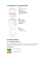
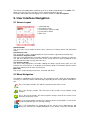
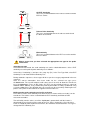
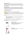
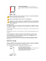
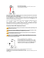
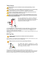
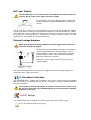
Apollo 600
Table of Contents
1. Limited Warranty & Limitation of Liability
2. Disposal of old product
3. Certificate of Conformity
4. User Notes
5. Safety Notes
6. Accessories
6.1 Standard accessories
6.2 Optional Accessories
7. Introduction to the Apollo 600
7.1 Front diagram
7.2 Top Diagram
7.3 Back diagram
8. Getting Started
8.1 Charging New Batteries
8.2 Power On
9. User Interface Navigation
9.1 Screen Layout
9.2 Menu Navigation
9.3 Battery Status
9.4 Test Functionality
10. Main Menu
10.1 View Saved Data
10.2 User Options
10.3 Bluetooth Setup
10.4 Automatic Test Sequence Editor (PAT Edit)
10.5 Download
10.5.1 Downloading into PATGuard 3
10.6 Upload
10.6.1 Uploading from PATGuard 3
10.6.2 Uploading a Logo for TnT Labels
10.7 Set Date and Time
10.8 Memory
11. Portable Appliance Testing
11.1 Automatic Test Sequence
11.1.1 Entering Asset Details
11.1.2 Using the Risk Based Retest Period Calculator
11.1.3 The Formal Visual Inspection
11.2 Manual Test Interface
11.3 Test Functions
Earth Continuity
Nulling out Test Leads
Insulation Resistance
Substitute Leakage
Protective Earth (PE) Conductor Current
Touch Current
RCD Trip Time
IEC Lead / Polarity
External Leakage Adaptors
11.4 Checkbox Verification
11.5 PAT Settings
12. Universal Risk Assessment
13. Health & Safety Reports
14. Updating your Firmware
15. Electrical Specification
16. Useful Information
16.1 Factory Set Test Sequences
16.2 Other Information
17. Environmental Conditions
18. Maintenance
18.1 Charging the battery pack.
18.2 Securing the Apollo 600
18.3 Cleaning the Apollo 600
18.4 Replacing the battery pack
19. Support
19.1 Registration
19.2Calibration
1. Limited Warranty & Limitation of Liability
SEAWARD Electronic Limited guarantees this product to be free from defects in material and
workmanship under normal use and service for a period of 2 years (subject to product
registration) provided that the instrument is serviced and calibrated by a Seaward approved
agent in accordance with the manufactures instructions. The period of warranty will be
effective at the day of delivery.
(c) Copyright 2013
All rights reserved. Nothing from this edition may be multiplied, or made public in any form or
manner, either electronically, mechanically, by photocopying, recording, or in any manner,
without prior written consent from SEAWARD Electronic Limited. This also applies to
accompanying drawings and diagrams.
Due to a policy of continuous development SEAWARD Electronic Limited reserves the right to
alter the equipment specification and description outlined in this publication without prior
notice and no part of this publication shall be deemed to be part of any contract for the
equipment unless specifically referred to as an inclusion within such contract.
2. Disposal of old product
This product has been designed and manufactured with high quality
materials and components that can be recycled and reused.
When this symbol is attached to a product it means the product is
covered by the European Directive 2002/96/EC.
Please familiarise yourself with the appropriate local separate collection system for electrical
and electronic products.
Please dispose of this product according to local regulations. Do not dispose of this product
along with normal waste material. The correct disposal of this product will help prevent
potential negative consequences for the environment and human health.
3. Certificate of Conformity
As the manufacturer of the apparatus listed, declare under our sole responsibility that the
product:
Apollo 600
To which this declaration relates are in conformity with the relevant clauses of the following
standards:
BS EN 61010-1:2010, BS EN 61010-1-030:2010, BS EN 61010-031:2008
Safety requirements for electrical equipment for measurement, control, and laboratory
use.
BS EN 61557-1,-2,-4:2007 & -10:2001
Electrical safety in low voltage distribution systems up to 1000V a.c. and 1500V d.c. –
Equipment for testing, measuring and monitoring of protective measures
BS EN 61326:2006
Electrical equipment for measurement, control and laboratory user-EMC Requirements
Performance: The instrument operates within specification when used under the conditions in
the above standards EMC and Safety Standards.
The product identified above conforms to the requirements of Council Directive 89/336/EEC
and 73/23 EEC.
Seaward Electronic Ltd is registered under BS EN ISO9001:2000 Certificate No: Q05356.
4. User Notes
These operating instructions are intended for the use of adequately trained personnel.
The following symbols are used in these operating instructions and on the Apollo 600.
Warning of electrical danger!
Indicates instructions must be followed to avoid danger to persons.
Caution, follow the documentation! This symbol indicates that the operating
instructions must be adhered to in order to avoid danger.
Note: Data may be lost or altered in virtually any electronic memory under certain
circumstances. Therefore Seaward Electronic assumes no responsibility for financial losses
or claims due to data lost or otherwise rendered unusable whether as a result of abuse,
improper use, defects, disregard of operating instructions or procedures, or any allied causes.
5. Safety Notes
This Apollo 600 has been built and tested in accordance with:
BS EN 61010-1: 2010.
BS EN 61557 part 1, 2, 4 and 10.
To ensure safe operation of the unit, all notes and warnings in these instructions must be
observed at all times.
If the Apollo 600 is used in a manner not specified by these operating
instructions then the protection provided may be impaired.
Always ensure that the circuit or appliance under test is electrically isolated.
Do not connect the Apollo 600 to electric circuits with nominal voltage greater
than CAT II 300 V AC/DC.
The Apollo 600 and all associated cables and leads must be checked for signs
of damage before equipment is operated. Do not use if there are signs of
damage. Only use the correct leads supplied with the Apollo 600.
Do not touch test probes beyond the hand barrier on the test probe.
The Apollo 600 may apply high voltage or mains power to the appliance under
test. Do not touch conductive parts of the appliance while tests are active.
If the Apollo 600 is being used to determine the presence or absence of
hazardous voltages, always prove the operation of voltage measurement
function before and after use by means of a known voltage source or proving
unit.
Do not operate the Apollo 600 in an explosive gas or dust environment.
The Apollo 600 has been designed to make measurements in a dry
environment.
The Apollo 600 includes a rechargeable battery pack which is charged while
the Apollo 600 is connected to a mains supply. Only a Seaward battery pack
should be connected into the Apollo 600. Disconnect the Apollo 600 from all
leads before opening the battery compartment.
Do not open the Apollo 600, no user serviceable parts.
Where safe operation of the Apollo 600 is no longer possible it should be immediately shut
down and secured to prevent accidental operation.
It must be assumed that safe operation is no longer possible:
- if the instrument or leads show visible signs of damage or
- the instrument does not function or
- after long periods of storage under adverse environmental conditions.
6. Accessories
6.1 Standard Accessories
The Apollo 600 is supplied with the following items:
Apollo 600 unit
Professional carry case
Seaward black power lead
Test lead, black, 1.2m
Alligator clip, black
Test lead, red, 1.2m
Alligator clip, red
IEC test lead
Test adaptor, 110V/230V
USB Download Lead
Apollo 600 Check Box
1
1
1
1
1
1
1
1
1
1
1
6.2 Optional Accessories
Test n Tag Elite Bluetooth Label Printer
Bluetooth Barcode Scanner
PATGuard 3 Software
3 Phase Leakage Adaptor 5 Star 16A
3 Phase Leakage Adaptor 5 Star 32A
3 Phase Adapter Delta 4 pin 16A 415V (for Rpe & IR)
3 Phase Adapter Star 5 pin 16A 415V (for Rpe & IR)
3 Phase Adapter Delta 4 pin 32A 415V (for Rpe & IR)
3 Phase Adapter Star 5 pin 32A 415V (for Rpe & IR)
339A970
339A923
see www.seaward.co.uk/PG3Trial
391A920
391A910
209A910
209A911
209A912
209A913
7. Introduction to the Apollo 600
Front
1. Test terminal end plate
2. LCD
3. Function keys
4. QWERTY keyboard
5. Test function STOP key
6. Test function START key
7. Arrow keys
Top
1. EUT test socket
2. IEC test socket
3. Red test terminal
4. Black test terminal
5. USB type B
6. USB type A
Back
1. Camera Lens
2. Flash source
3. Battery compartment
8. Getting Started
8.1 Charging New Batteries
Before using Apollo 600 for the first time please ensure that you fully charge the unit using the
Seaward black power lead plugged into the mains inlet socket on the top of the tester.
8.2 Power On
This is the Power On button.
This is the Power Off button
The first time the Apollo 600 is powered up the User will be automatically set to admin. The
admin user gives full access to all the menus and functionality of the unit.
For further information about changing User and Password see 10.2 User Options.
9. User Interface Navigation
9.1 Screen Layout
1. Information bar
2. Function key icons
3. Test interface sequence table
4. Test interface details
5. Main area
Information Bar
This area of the screen shows the Date, Time, Current User, Battery Status and Connection
Status.
Function Key Icons
This area of the screen is used to identify the current action assigned to the function keys.
Test Interface Sequence Table
This area is only displaying in test mode showing the tests within the selected test sequence.
This will also show the results and status of the results that have been performed. In the
manual mode this table may only show one test.
Test Interface Details
This area is only displayed in test mode showing the details specific to the active test. This
includes the measurement, an analogue measurement graph, the duration and limit. Some
tests may show more than more measurement.
Main Area
This area is used to display menu items, text fields and forms.
9.2 Menu Navigation
The Apollo is controlled by the function keys. The function key icons, which are located above
each key, are context sensitive and will change depending on the current options available to
you.
This is the Home function. This will take you back to the Home screen.
This is the Escape function. This will return to the previous screen without saving
changes.
This is the Accept function. This will accept the changes made in the current screen
and move to the next screen.
This is the Setup Options function. This will take you the Setup Options screen for the
specific function that you are currently viewing.
This is the information key. Depending on the current screen displayed this will
display the manual or the Apollo 600 details, in the details screen this function will
display the manual.
This is the Menu/Options key. This function will bring up a context sensitive menu
giving the options available for the current screen.
This is the Save key. This function is used to save data/changes that you have made
on the current screen.
This is the camera function. This function will appear when you are able to take
photographs.
9.3 Battery Status
While the Apollo 600 is powered on there are periodic checks of the batteries. The Apollo 600
will show the status of the batteries
This symbol indicates that the batteries are at 100% capacity.
There are several symbols which will display the current battery voltage. When these
icons are displayed the batteries are still good.
This symbol indicates that the batteries are low. Although tests performed with the
batteries in this state are still valid all test types may not complete their intended
duration.
This symbol indicates that the batteries are discharged. The Apollo 600 will switch
itself off after a short period of time.
This symbol indicates that the Apollo 600 is bulk charging batteries at the full charge
current.
This symbol indicates that the Apollo 600 is trickle charging the batteries with
reduced charge current. This is known as the Top Up Charge.
This symbol indicates that the Apollo 600 has detected a fault with the battery or
battery charger circuit. Unplug the Apollo 600 from the mains supply and wait 2
minutes before reconnecting the mains. If the fault persists then return the Apollo
600 for service.
Please note that the battery symbols are not updated in real time and may take a while to
update.
9.4 Test Functionality
There are two buttons which control the starting and stopping of the selected test type.
This is the Start Test button. This is used to start electrical tests.
This is the Abort Test button. This is used to stop electrical tests.
10. Main Menu
10.1 View Saved Data
This will allow you to view any data that you have saved in the Apollo 600. By selecting this
icon in the Main Menu you can view a list of all saved Asset IDs by site and location.
Use the arrow keys to scroll up and down.
This is the Accept function. This will open the selected record.
This button allows you to filter records to give a customised view. Select the filters you
wish to apply and press ‘Accept’.
Once in the record you will be given a list of items under that record such as PAT results and
JPEG images. Press Accept to open.
When viewing a PAT_results record the Menu icon will become available so that you can
view results or print labels.
When viewing a saved Health & Safety Form you can edit the report and then save the
changes.
This will create a new time and date stamped report as well as saving the original.
This is the Menu/Options key. This function will bring up a context sensitive menu
giving the options available for the current screen.
10.2 User Options
Apollo 600 has one default user account set up as admin who will have full access to the
product.
This is where you can set up new, edit and delete user accounts. Users can alter their own
screen power save time, Auto power down, background image, avatar and power on screen
and press Save to apply.
Use this button to Change User. You can then select the User name and enter the
correct password to change the current user of the tester. You can also change the
password of the current user by selecting ‘change password’ and entering the old
password and entering a new one then confirming it.
Use this button to Change Password of the current user by selecting ‘change
password’ and entering the old password and entering a new one then confirming it.
This User Privileges menu allows users to view their current privileges. If they have
‘Edit users’ rights they will also be able to edit their own and other users privileges by
selecting the user they wish to edit from the dropdown.
This is the New User button. Here you can set up a new user account by adding a
username and password and pressing ‘Save. You can then select their name from the
dropdown in the User Privileges screen, select the type of user (Expert or Novice) and
set up their privileges by pressing the Enter key to check or uncheck. If a privilege is
checked, the user has access to that feature or function. To block a feature or
function, e.g. adjusting the time and date or editing test sequences, uncheck that
function before saving.
This is the Delete User button. It will delete whichever user is currently selected in the
‘Username’ dropdown.
Please note that the admin user cannot be deleted.
Press this button to Save changes and return to the previous screen.
This is the Copy User function. This will copy the settings and preferences of the
current user to a new user account.
10.3 Bluetooth Setup
Select this icon to setup your Bluetooth accessories to work with the Apollo 600. Switch on
the Bluetooth device you wish to pair with and ensure it is discoverable.
This will Bluetooth Search button will search the area for Bluetooth discoverable
devices and return to the previous menu. You can then use the arrow keys to select
the correct Bluetooth ID from the dropdowns for your Bar Code Scanner, Printer or
Mobile Device. Press ‘Save’ once complete.
Press this button to save changes and return to the previous screen.
10.4 Automatic Test Sequence Editor (PAT Edit)
Although the Apollo 600 comes with a number of pre-defined test sequences you can modify
existing, or create new test sequences of their own.
From the Menu function key select one of the following options using the arrow keys and the
Accept button.
This is the Menu/Options key. This function will bring up a context sensitive menu
giving the options available for the current screen.
This is the Accept function. This will open the selected option.
Edit
Edits the highlighted sequence.
Copy
Makes a copy of the highlighted test sequence.
Delete
Deletes the highlighted test sequence.
Add New
Adds a new test sequence to the bottom of the list.
Insert New
Adds a new test below the highlighted test sequence.
When editing a test sequence the following functions are available
This is the Add Test function. This will add a new test directly under the currently
selected test.
This is the Delete Test function. This will delete the highlighted test from the test
sequence.
This is the Edit Test function. This will edit the highlighted test.
10.5 Download
10.5.1Downloading to PATGuard 3
You can download the data from your Apollo to PATGuard 3 software.
In the Download menu select To PATGuard in the Download data from Apollo dropdown.
This button allows you to filter records for download. Select the filters you wish to
apply and press Accept.
This is the Accept function. This will accept the changes made in the current screen
and move to the next screen.
You then need to select one of 3 options from the using dropdown:
Flash Memory Stick
Insert a USB flash memory stick into the USB type A port on the Apollo 600. Press ‘Save’.
Instructions for how to import this download into PATGuard 3 can be found in the PATGuard
3 help files.
USB-PC cable
Connect the USB download cable to the USB type B port on the Apollo 600 and to a USB port
on your PC. Press Save.
Instructions for how to import this download into PATGuard 3 can be found in the PATGuard
3 help files.
Bluetooth to Mobile Device
You will need to have a Bluetooth enabled mobile device configured with the Apollo 600 to
use this method. See 10.3 Bluetooth Setup.
10.6 Upload
10.6.1 Uploading from PATGuard 3
Uploading of records from PATGuard 3 is not available in this firmware version. Please go to
www.seaward.co.uk/firmware to download the latest Apollo 600 firmware file.
See 14. Updating Your Firmware section.
10.6.2 Uploading a Logo for TnT Labels
A bitmap logo can be transferred to the Apollo 600 for use with the Seaward Test ‘n’ Tag print
system. The logo must be in .BMP with a maximum size of 320 pixels by 240 pixels.
Save the logo you wish to use onto a USB memory stick.
In the Upload menu select Printer Logos from the Upload data into Apollo dropdown.
Select Flash Memory Stick in the using dropdown.
Insert the USB memory stick.
Press the Save button to save the logos to the Apollo 600.
See Printing a Label.
10.7 Set Date and Time
You can change the date and time in this menu using the arrow keys and number keys.
Press this button to save changes and return to the previous screen.
10.8 Memory
This section will allow you to view how much memory space you have used and how much is
left.
This is the Restore button. Selecting this will allow you to clear memory or reset
factory settings. Select what you would like to restore by pressing the Enter button.
Press this button to save changes and return to the previous screen.
11. Portable Appliance Testing
11.1 Automatic Test Sequence
The Apollo 600 comes with a number of pre-defined test sequences (see 16.1 Factory Set
Test Sequences). These test sequences can include any combination of electrical or user
defined tests. These test sequences are performed on equipment to ensure that it meets the
safety requirements outlined in the IET Code of Practice for In-service Inspection and Testing
of Electrical Equipment.
11.1.1 Entering Asset Details
Asset ID
This is unique identifier for the equipment under test. This can be
entered using the keypad, a barcode scanner (see 10.3 Bluetooth
Setup), or set to automatically increment (see 11.4 PAT Settings).
Test Sequence
This is the name of the pre-defined test sequence which will be
performed on the equipment.
Site
This is the site where the equipment is located. You can choose a site
from the dropdown using the arrow keys or enter a new one.
Location
This is the location within the site where the equipment is. You can
choose a location from the dropdown using the arrow keys or enter a
new one.
Retest Period
(Visual)
This is the period, in months, in which the equipment should be reinspected. This can be completed manually or the ‘Risk Based Retest
Period Calculator’ can be used.
Retest Period (Full) This is the period, in months, in which the equipment should be retested. This can be completed manually or the ‘Risk Based Retest
Period Calculator’ can be used.
You can use the Camera function to attach photos to the asset record.
This button will enable and disable the flash light.
Press this button to take the picture.
This button will attach the picture and go back to the record. To add another picture
press the ‘Camera’ button again.
This button will cancel the picture and allow you to take another.
11.1.2 Using the Risk Based Retest Period Calculator
The Risk Based Retest Period Calculator will allow you to select options using the
arrow keys from the dropdowns. It will then determine if the asset is Low or High risk
and advise retest periods for Formal Visual and Full Test.
This is the Accept function. This will accept the changes made in the current screen
and move to the next screen.
11.1.3 The Formal Visual Inspection
All preset test sequences start with a Visual Inspection.
Using the Camera in this screen will tag the picture to the test result.
This is the Pass Icon.
This is the Fail icon.
This means that the inspection is not applicable to the EUT.
Pass Pressing the Pass All button will apply a pass to all relevant inspections and move
All onto the next test.
11.1.4 The Electrical Tests
The Apollo 600 has probe detection that will automatically flag up if you do not have the
correct probe configuration for the test you are trying to perform.
During the tests you can see the test duration, limit and result on screen, see 9.1 Screen
Layout.
Should any test with the sequence fail the sequence will be aborted and you will presented
with the Notes screen by default but this can be changed, see 11.5 PAT Settings.
11.1.5 Printing a Label
If you have a TnT Bluetooth printer configured with the Apollo 600 you can set it to
automatically print a label after each test.
In PAT Settings set After Test to Print Label and press Save.
See 10.3 Bluetooth Settings & 11.5 PAT Settings.
This is the Tools function. This function allows you to configure the label Title, select
a Pass or Fail Logo, change print density and select which pre-configured label
printer to use.
This is the Change Format function. This will change the format of the label
11.2 Manual Test Interface
The Apollo 600 allows direct access to all of the electrical tests through Manual Mode.
Within each test there are a number of function key options;
This is the Tools function. This function allows you to configure the test current test
type, this includes;
- test duration
- test pass/fail limit
- test type/connection
Always ensure that you have selected the correct test connection method in
the test for the probe connections made.
Please refer to the Test Functions section for specific information about each test type.
11.3 Test Functions
Earth Continuity
Always ensure that the circuit under test is electrically isolated.
Note that measurements can be adversely affected by parallel resistances of
additional circuits or by transient currents.
Connecting a test probe to a hazardous voltage when a point to point
measurement is active will result in that voltage being present on the other test
probe.
This test is applicable to Class I equipment. This test will measure one of the following:
resistance between the protective earth terminal in the EUT mains plug and the point
at which a single test probe is applied – CLI EUT Continuity
• resistance between two test probes – Point to Point Continuity
• resistance between the protective earth terminal in an IEC lead mains plug and the
protective earth terminal in the IEC connector – IEC Continuity
to ensure that the connection is satisfactory and of sufficiently low resistance. The
measurement will be displayed in Ohms.
There are three possible connection methods for the Earth Continuity test.
•
CLI EUT Continuity
The test is performed between the red test terminal and the
EUT test socket.
Point to Point Continuity
This test is performed between the red test terminal and
the black test terminal.
IEC Continuity
The test is performed between the EUT test socket and the
IEC test socket.
Always ensure that you have selected the appropriate test type for the probe
connections.
Selecting test type
In manual PAT test mode, the earth continuity test can be switched between a Class I EUT
continuity test and a point to point continuity test as follows:
Select Class I Continuity (1) and press the setup key (F3). In the Test Type field, select EUT
Continuity Test or Point to Point Continuity Test.
During automatic sequences, the test type will be as per the test type programmed in the test
sequence.
Once the correct connections have been made for the selected test type press
the Start button. The test will continue until it times out. If we wish to abort the current test
press the Stop button. Tests on IEC leads, CLI EUTs can be performed using a current of
+200mA and/or -200mA. Tests performed in point to point mode are always performed using
a current +200mA test. The direction of the test current can be reversed by switching the test
probes at the point of connection to the appliance/circuit under test.
Nulling out the earth continuity test lead(s) resistance
For a more accurate earth continuity measurement, the resistance of the test lead(s) can be
zeroed out. The feature can be used with both the EUT Continuity and Point to Point
measurement modes.
The null facility remains active, even if the Apollo 600 is powered off, until the feature is
deactivated by pressing the null key again or the Test Type is changed e.g. if a pair of test
leads are nulled for point to point measurement, the null will be deactivated if the Test Type is
changed to EUT Continuity test.
Nulling a single test lead
In the manual PAT screen, press the setup key (F3) and change the Test Type to EUT
Continuity Test. Press save (F4). Connect the earth continuity test lead to the earth continuity
test socket and connect the probe tip to the earth pin of the EUT socket. Press Null (F4) to
measure and stored the test lead resistance. When the null feature is active the Null icon will
appear on the display.
Nulling both test leads
In the manual PAT screen, press the setup key (F3) and change the Test Type to Point to
Point Continuity Test. Press save (F4). Connect both earth continuity test leads to the earth
continuity test sockets and connect the probe tips together using the supplied alligator clips.
Press Null (F4) to measure and stored the test lead resistance. When the null feature is active
the Null icon will appear on the display.
Insulation Resistance
Always ensure that the circuit under test is electrically isolated.
Connecting a test probe to a hazardous voltage when a point to point
measurement is active will result in that voltage being present on the other test
probe.
This test is applicable to Class I and Class II equipment. This test will measure one of the
following:
•
•
•
insulation resistance between live circuits and the protective earth circuit in the EUT –
Class I / IEC lead insulation test
insulation resistance between live circuits and a test probe applied to the EUT –
Class II insulation test
insulation resistance between two test probes – Point to Point Insulation
to ensure that the test points are adequately insulated from one another. The measurement is
displayed in MOhms.
There are three possible connection methods for the Insulation test.
CLI and IEC Insulation
The test is performed between the EUT test socket live and
neutral and the EUT test socket earth pin.
For IEC leads the other end of the lead should be
connected into the IEC test socket.
CLII Insulation
The test is performed between the EUT test socket live and
neutral and Red test terminal.
Point to Point Insulation
The test is performed between the Red and Black test
terminals, both the continuity test leads are required for this
test.
Always ensure that you have selected the correct test connection method in
the test for the probe connections made.
Ensure that the appliance mains switch is in the ON position.
During this test, 250V or 500V D.C. is applied between the two connections
points. The 500V D.C. potential will be present across the two probe tips during
a Point to Point test.
Selecting test type
In manual PAT test mode, the insulation test can be switched between a 250V EUT Insulation
test, 500V EUT Insulation test, 250V Point to Point Insulation test or 500V Point to Point
Insulation test as follows:
Select Insulation Resistance (2) and press the setup key (F3). In the Test Type field, select
the required test.
During automatic sequences, the test type will be as per the test type programmed in the test
sequence.
In manual mode once the correct connections have been made for the selected test type
press the Start button, in automatic mode the test will proceed automatically. The test will
continue until it times out. If we wish to abort the current test press the Stop button. The
measurement will be displayed in Mega Ohms.
If an EUT fails the Insulation test then this may be because of internal filtering or an MOV.
Retry the test at 250V or substitute the Insulation test with a Protective Conductor or Touch
Current test.
Substitute Leakage
This test is applicable to Class I and Class II equipment. This test is used to verify that the
leakage between the mains conductors of the EUT to the EUT earth pin, or conductive
accessible surface of the enclosure, is to a satisfactory low level.
There are two possible connection methods for the Substitute Leakage test.
CLI and IEC Substitute Leakage
The test is performed between the EUT test socket live and
neutral and the EUT socket earth pin.
For IEC leads the other end of the lead should be
connected into the IEC test socket.
CLII Substitute Leakage
The test is performed between the EUT socket live and
neutral and Red test terminal.
During this test, 40V A.C. is applied between the earth pin and both the live and neutral
pins of the appliance mains supply plug.
In manual mode once the correct connections have been made for the selected test type
press the Start button, in automatic mode the test will proceed automatically. The test will
continue until it times out. If we wish to abort the current test press the Stop button. The
measurement will be displayed in milli Amps.
This test can prove useful in situations where neither conventional insulation nor flash tests
are
acceptable
methods
of
testing
the
insulation
of
the
appliance.
Please note that values for substitute leakage may differ substantially from that of
conventional earth leakage tests because of the way that the test is performed (e.g. it will be
affected by the presence of Neutral-to-Earth suppression capacitors).
Protective Earth (PE) Conductor Current
Always test the earth continuity and insulation resistance before performing a PE
Conductor Current test.
Always check that an appliance with moving parts (e.g. an electric drill) is safely
mounted to avoid risk of damage to equipment or personnel.
Avoid prolonged, repeated use at full load (16A) and excessive test duration as
this may reduce the life of the unit.
Always ensure that appliance and leads, which include RCD protection, that the
RCD is reset at the beginning of the test. Failure to do so may result in incorrect
measurements being recorded.
This test is applicable on Class I Equipment.
The Apollo 600 should be connected to a mains supply.
The EUT should be connected into the EUT test socket.
In manual mode once the correct connections have been
made for the selected test type press the Start button, in
automatic mode the test will proceed automatically.
The test will continue until it times out. If we wish to abort the current test press
the Stop button. The measurement will be displayed in mA.
Should the test measurement over range then the test will be aborted immediately and a fail
will be logged.
Touch Current
Warning: Always test the insulation resistance before performing a Touch
Current test.
Warning: Always check that an appliance with moving parts (e.g. an electric drill)
is safely mounted to avoid risk of damage to equipment or personnel.
Attention: Avoid prolonged, repeated use at full load (16A) and excessive test
duration as this may reduce the life of the unit.
Always ensure that appliance and leads, which include RCD protection, that the
RCD is reset at the beginning of the test. Failure to do so may result in incorrect
measurements being recorded.
This test is applicable on Class I and Class II Equipment.
The Apollo 600 should be connected to a mains supply.
The EUT should be connected into the EUT socket, the red
test terminal should be connected to point at which the
leakage measurement is required.
In manual mode once the correct connections have been made for the selected test type
press the Start button, in automatic mode the test will proceed automatically. The test will
continue until it times out. If we wish to abort the current test press the Stop button. The
measurement will be displayed in milli Amps.
Should the test measurement over range then the test will be aborted immediately and a fail
will be logged.
RCD Trip Time
Voltages between the protective conductor and earth may influence
measurements.
This test will pass a sinusoidal current of 30mA between the EUT socket and the IEC socket,
and measure the time it takes for the in-line RCD to trip.
Remove all other connections before performing an RCD test.
The Apollo 600 should be connected to a mains
supply. The RCD should be plugged into the EUT test
socket and a connection should be made from the RCD
mains output to the IEC test socket.
Once the correct connections have been made for the selected test type press
the Start button. The RCD will be powered and you will be prompted to reset the RCD. When
you have reset the RCD the Apollo 600 will count down and then perform the RCD test, the
RCD trip time will be displayed. The measurement will be displayed in milli seconds.
IEC Lead / Polarity
The IEC lead input is a test socket and is not intended to be connected directly
to mains. Do not connect this input to the mains supply.
The Polarity test checks the wiring polarity of an IEC lead,
the IEC should be plugged into both the EUT and IEC test
sockets.
This test can be used to test the wiring polarity of extension leads by plugging the supplied
test IEC lead into the end of the extension lead to complete the circuit to the IEC tests socket.
In the automatic sequence editor the Polarity can be added to sequence. In the manual mode
the polarity test is already part of a pre-defined test sequence which includes an Earth
Continuity test, an Insulation test and the Polarity test.
External Leakage Adaptors
While using an External Leakage Adaptor the mains supply will be connected
to the EUT through the adaptor.
The External Leakage Adaptor test function is intended to
used in conjunction with the one of Seaward's external
leakage adaptors. Connect the external leakage adaptor
into the Red test terminal, connect the Earth Continuity
probe into the Black test terminal.
Connect the mains supply and the EUT to the external
leakage adaptor.
Note that connecting both the EUT and mains supply to the external leakage adaptor will
connect the mains supply to the EUT.
11.4 Checkbox Verification
The Apollo 600 comes supplied with a Checkbox. This can be used to verify that the Apollo
600 test functions are working correctly. When selecting the Checkbox function follow the
onscreen instructions.
The Checkbox function will perform a number of electrical tests. Ensure that
the onscreen instructions are followed and that you do not touch the checkbox
during the active tests.
11.5 PAT Settings
This function allows you to configure the below factors with relation to PAT testing.
Press this button to go to the next page.
Press this button to go to the previous page.
Press this button to save changes and return to the previous screen.
Asset ID
This can be set to present a blank field, repeat the last Asset ID or automatically
increment the Asset ID number for each successive test.
Start
This field is used to set the starting point for the auto increment feature. The
Increment value entered can be numeric or alpha-numeric ending with a numerical value.
On Test
Failure
In the event of a test failure during an automatic sequence, the Apollo 600 can
be configured to either End Test, which will terminate the test sequence or
present a Fail Menu, which will provide the following list of options:
•
•
•
•
•
restart the test
skip the test
restart the test sequence (from the first test)
abort the test sequence (without saving any results
end the test sequence (and record a fail result)
Note: Restart Test is useful for coping with situations such as forgetting to
connect the earth continuity probe.
End Test Sequence will record a Fail result whereas Abort Test
Sequence does not record a result.
After Test There is a choice of 3 actions to be carried out at the end of a test sequence.
New Test will auto save at the end of a test sequence and then open the Asset
Details window ready for a new test.
Print Label will auto save at the end of a test sequence and then open the Print
Label window. When printing is complete, the tester will proceed to the next test
and open the Asset Details window.
Options Menu will auto save at the end of a test sequence and then open the
Test Details window. Pressing (F4) will proceed to the Test Result Options
window with a list of options including View Results, View Test Sequence,
Information, Print Test Results or Print Label. Pressing Escape (F5) will return to
the Asset Detail window ready to start the next appliance.
Earth
Result
This field can set to “Last” where the last reading taken during the measurement
period is compared with the pass/fail limit or “Worst” where the highest reading
taken during the measurement period is compared wit the pass/fail limit.
Setting the field to “Worst” will cause the earth continuity test to fail if the reading
exceeds the limit value at any point during the measurement period, for example
if there is a momentary break in the protective conductor when the mains cable
is flexed.
Earth
reverse
This field is used to enable or disable automatic reversal of the earth continuity
test current polarity. OFF sets the earth continuity test current to +200mA and
ON sets the earth continuity test current to +200mA followed by -200mA.
Sub Lkg
Factor
This field is used to set the substitute leakage scale factor to 0%, 6% or 10%.
The Substitute Leakage reading is then calculated for 230V (0%), 244V (6%) or
253V (10%).
Comments Can be set to open the comment window: always (after every test sequence), if
the test result is a pass, if the test result is a fail or never.
New
This field can be set to Clear where previous comments are removed from the
Comments comments fields or Same as Last where the previous remain in the comments
fields. This can be useful when performing repeated tests on the same type of
appliance.
Comments This allows the field descriptor for each of the four comment lines to be changed
Line
to show Notes, Asset Description, Asset Group, Make, Model or Serial Number
or Location as required.
CheckBox This field is used to set the frequency of the CheckBox reminder to none, daily,
Interval
weekly or monthly.
12. Universal Risk Assessment
This menu allows you to complete risk assessments for any workplace hazard and calculate a
risk score.
This is the Settings function. This function allows you to configure settings such as
how the Hazard ID should be filled.
Add new Hazard. This will take you to fill in the Hazard ID, if necessary. Select a Site
and Location from the dropdown using the arrow keys or enter a new one if
necessary.
Press the ‘Accept’ button to fill in the form.
Use the arrow keys to move through the form and the QWERTY keyboard to fill in the
relevant fields.
Use the right and Left Arrow keys to select ‘Impact of Risk event’ and ‘Probability of
Occurrence’.
This will give a calculated score between 1-12 for ‘Priority of Risk Level’ and ‘Advice’ based
on this score.
If necessary you can ‘Add’ corrective actions, assign them to personnel and give
dates for completion.
You can use the Camera function to attach photos to the record.
This button will enable and disable the flash light.
Press this button to take the picture.
This button will attach the picture and go back to the record. To add another picture
press the ‘Camera’ button again.
This button will cancel the picture and allow you to take another.
Press this button to save changes and return to the previous screen.
13. Health & Safety Reports
This menu allows you to complete and save Health & Safety forms such as Emergency
Lighting and Fire Alarm & System Inspection reports.
To fill in a new form
Fill in the form ID number and select a Site and Location from the dropdown using the arrow
keys or enter a new one if necessary.
Select which form you wish to complete from the dropdown using the arrow keys.
Press the ‘Accept’ button to open the form.
Use the arrow keys to move through the form and the QWERTY keyboard to fill in the
relevant fields.
You can use the Camera function to attach photos to the record.
This button will enable and disable the flash light.
Press this button to take the picture.
This button will attach the picture and go back to the record. To add another picture
press the ‘Camera’ button again.
This button will cancel the picture and allow you to take another.
Press this button to save changes and return to the previous screen.
14. Updating your Firmware
1.
Go to www.seaward.co.uk/firmware and save the latest Apollo 600
firmware file to a USB memory stick.
2.
Power on the unit whilst holding down the F1 button.
3.
Press F2 to update via memory stick.
4.
Follow the onscreen instructions.
5.
Restart the unit.
You can check the firmware version of your tester by pressing this icon in the Home
screen.
15. Electrical Specification
Earth Continuity
Output Current (Load 2Ω):
Test Voltage (o/c) :
Measuring Range:
Display Range:
Resolution:
Operating Error:
Number of tests as per IEC615574:
+/- 200mA DC with ZAP
> 4VDC
0.05Ω – 19.99Ω
0.01Ω – 19.99Ω
0.01Ω
+/-5% + 2 counts
approx 1,500.
Insulation Test
Test Voltages:
Test Current:
500V and 250V DC
1mA minimum for a load of 1kohm/volt,
<2mA into s/c
Test Voltage Accuracy:
+20%, -0%
Measuring Range:
0.10MΩ to 19.99MΩ
Display Range:
0.00MΩ to 19.99MΩ
Resolution:
0.01MΩ
Operating Error:
+/-5% +5 counts (0.10MΩ to 9.99MΩ)
+/-10% +5 counts (10.00MΩ to 19.99MΩ)
Number of tests as per IEC61557- approx 1,500.
2:
Subsitute Leakage Test
Test Voltages:
Measuring Range:
Display Range:
Resolution:
Operating Error:
>25Vac <50Vac
0.20mA to 19.99mA
0.00mA to 19.99mA
0.01mA
+/-10% +2 digits
Protective Conductor Current
Test Voltage:
Display Range:
Measurement Range:
Resolution:
Operating Error:
Frequency Response:
Supply Voltage, maximum
load current 16A
0.01mA to 19.99mA
0.25mA to 19.99mA
0.01mA
+/-5% of reading +/- 3 digits
40Hz to 2.5 kHz
Touch Current
Test Voltage:
Display Range:
Measurement Range:
Resolution:
Operating Error:
Frequency Response:
Supply Voltage, maximum
load current 16A
0.00mA to 3.50mA
0.10mA to 3.50mA
0.01mA
+/-5% of reading +/- 2 digits
DC to 2.5 kHz
Load Power/Current
Test Voltage:
Display Range:
Measurement Range:
Resolution:
Operating Error:
Supply Voltage, maximum
load current 16A
0.00 - 16.00A
0.50 - 16.00A
0.01A
+/-10% of reading +/- 5 digits
Lead Test
Test Voltage:
Test:
5V DC nominal
Live / Neutral checks for o/c,
s/c and crossed
Power Socket Test
Input voltage range:
195V – 253V AC
Indicates configuration of
voltage potential:Line potential phase to earth
Line potential phase to neutral
Line potential neutral to earth
RCD Test
Test Voltage:
Test Current:
Test Current Accuracy:
Display Range:
Measuring Range:
Resolution:
Operating Error:
230V +10%, -15%
15mA / 30mA rms sinusoidal
15mA -10% +0%, 30mA +10, 0%
0 – 2000ms
1ms – 2000ms
1ms
±1ms
External Leakage
Test Voltage:
Display Range:
Measuring Range:
Resolution:
Operating Error:
Connected to External Adapter
0mA - 9.99mA
0.25mA - 9.99mA
0.01mA
+-5%of reading +-2 digits
16. Useful Information
16.1 Factory Set Test Sequences
Visual
Earth Continuity
PE Conductor
Current
Insulation
Touch Current
Substitute
Leakage
Wiring
RCD
Trip
Time
Test
Name
Portable/Handheld/IT CLI
Portable/Handheld/IT CLII
Fixed Appliance CLI
Fixed Appliance CLII
IEC Lead 2m
13A 5m Surge Protected Lead
13A 25m Ext Lead 30mA RCD
Portable CLI PE Current
Portable CLII Touch Current
IT Equip CLI PE Current
IT Equip CLII T ouch Current
13A 6m Mains Lead
13A 12m Mains Lead
13A 24m Mains Lead
Mov/Stat CLI 500V Insulation
Yes
Yes
Yes
Yes
Yes
Yes
Yes
Yes
Yes
Yes
Yes
Yes
Yes
Yes
Yes
Duration
(s)
Limit
(Ω)
Duration
(s)
Voltage
Limit
(MΩ)
5
0.1
2
0.1
5
5
5
5
0.2
0.2
0.5
0.5
2
2
5
5
2
2
500
500
500
500
500
250
1
2
1
2
1
1
5
5
5
5
5
0.1
0.2
0.3
0.5
0.1
2
2
2
2
2
2
2
2
250
250
250
250
500
500
500
500
1
2
1
1
1
1
1
Duration
(s)
Limit
(mA)
Duration
(s)
Limit
(mA)
Duration
(s)
Limit
(mA)
Limit
(ms)
Yes
Yes
5
5
5
0.8
0.8
30
5
0.3
5
0.3
3.5
Yes
Yes
Yes
Visual
Earth Continuity
PE Conductor
Current
Insulation
Touch Current
Substitute
Leakage
Wiring
RCD
Trip
Time
Test
Name
Mov/Stat CLII 500V Insulation
Mov/Stat CLI PE Current
Mov/Stat CLII Touch Current
110V Handheld/Portable CLI
110V Handheld/Portable CLII
110V Movable/Stationary CLI
110V Movable/Stationary CLII
110V 25m Lead
Rpe&Insulation
Visual Only
Yes
Yes
Yes
Yes
Yes
Yes
Yes
Yes
Yes
Duration
(s)
Limit
(Ω)
5
0.1
5
0.1
5
0.1
5
0.5
Duration
(s)
Voltage
Limit
(MΩ)
2
2
2
2
2
2
2
500
250
250
500
500
500
500
2
1
2
1
2
1
2
2
500
1
Duration
(s)
Limit
(mA)
5
3.5
Duration
(s)
Limit
(mA)
5
3.5
Duration
(s)
Limit
(mA)
2
2
2
2
0.8
0.3
3.5
0.3
Limit
(ms)
16.2 Other Information
Parameter
Earth Continuity P/F limit (Ω)
Earth Continuity Duration (s)
Insulation Resistance P/F limit (MΩ)
Insulation Resistance Duration (s)
Substitute Leakage P/F limit (mA)
Substitute Leakage Duration (s)
IEC Cord Earth Continuity P/F limit
(ohms)
IEC Cord Insulation P/F limit (MΩ)
Touch Current P/F limit (mA)
Touch Current Duration (s)
PE Conductor Current P/F limit (mA)
PE Conductor Current Duration (s)
External Adapter Continuity (Ω)
External Adapter Leakage (mA)
External Adapter Duration (s)
RCD 30mA trip time (ms)
RCD 150mA trip time (ms)
Number of tests in a test sequence
Characters in a test sequence name
Characters in a User Test name
Characters in a User Test Unit
Total number of Test Sequences
Test Results Memory (Mbytes)
Test Results (typical)
Sites
Characters in Site name
Locations
Characters in Location name
Users
Characters in User name
Comments List
Characters in Comment
Characters in Asset ID
Default
0.1
5
1
5
0.75
5
Min
0.01
2
0.01
2
0.25
2
Max
19.99
30
19.99
30
15
30
0.1
1
0.25
5
0.75
5
0.1
0.75
5
200
40
0.01
0.01
0.25
2
0.25
2
0.01
0.25
2
1
1
1
1
1
5
19.99
3.50
30
19.99
30
5
9.99
30
2000
40
60
30
15
15
100
300
50000
100
15
100
15
50
15
100
25
15
1
1
1
1
17. Environmental Conditions
The Apollo 600 has been designed to perform tests and measurements in a dry environment.
Maximum barometric elevation for making measurements is 2000M.
Pollution degree 2 according to IEC 60529.
Electromagnetic compatibility (EMC). Interference immunity and emitted interference
conforming to IEC 61326-1.
Operating temperature range of 0 to 40 degrees C, without moisture condensation.
Operating Altitude 0 to 2000 metres.
18. Maintenance
18.1 Charging the battery pack.
The battery pack will be charged whenever the Apollo 600 is connected to the mains supply
regardless of whether it is switched on or off.
The typical charging current is set to 500mA but this may vary as the instrument also includes
pre-charge and top up charge modes.
When no tests are being performed the battery pack will be fully re-charged after 7 hours.
18.2 Securing the Apollo 600
Under certain conditions safe operation of the Apollo 600 can no longer be assumed:
Visible damage of the instrument case.
Incorrect measurement results.
Recognisable abuse to the instrument due to prolonged storage under improper conditions.
Recognisable abuse to the instrument due to extraordinary transportation stress.
In these case the Apollo 600 should be immediately switched off, disconnected from any test
and measurement function and secured to prevent any further use.
18.3 Cleaning the Apollo 600
Clean the external case of the Apollo 600 with a dry clean cloth.
Avoid using solvents and abrasive scouring agents to clean the external case of the Apollo
600.
18.4 Replacing the battery pack.
Before opening the Apollo 600 battery compartment ensure that all test leads
and accessories are disconnected.
Power off the instrument.
Disconnect all test leads and accessories.
Position the instrument face down and remove the screw holding the battery compartment
cover in place.
Remove the battery compartment cover.
Remove the battery pack from the compartment and unplug the 4 way connector.
Connect the 4 way connector of the new battery to the 4 way header in the battery
compartment, put the battery pack into the compartment.
Relocate the battery compartment cover and fasten in position with the battery compartment
screw.
ONLY USE A REPLACEMENT BATTERY PACK THAT HAS BEEN SUPPLIED BY
SEAWARD OR A SEAWARD APPROVED DISTRIBUTOR.
19. Support
The Apollo 600 must be registered with Seaward before support will be made available.
For Technical Support contact:
Tel: (+44) 191 587 8718
For help or advice on Service and Calibration contact:
CalibrationHouse
Seaward Electronic
Bracken Hill
South West Industrial Estate
Peterlee
Co Durham SR8 2SW
England
Tel: (+44) 191 5878739
(+44) 191 5878737
Email: [email protected]
Calibration House is part of the Seaward Group.
19.1 Register your product here:-
www.seaward.co.uk
19.2 Calibration Services:-
www.calibrationhouse.co.uk
Bracken Hill
South West Industrial Estate
Peterlee
County Durham
SR8 2SW
Co Durham SR8 2SW
England
Tel: (+44) 191 5863511
Part Number 380A558 Revision A
October 2012
© 2013 Seaward Electronic Ltd
Some icons provided by Fat Cow (http://www.fatcow.com/free-icons/)
Based in part on the work of the Qwt project (http://qwt.sf.net)