1
SEARS
another free manual from www.searstractormanuals.com
OWNERS
MANUAL
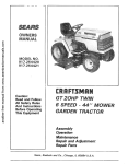
MODEL NO.
917.255917
[RRFTSMRN
Caution:
Read and Follow
All Safety Rules
And Instructions
Before Operating
This Equipment
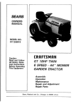
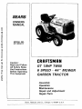
GT 18HP TWIN
6 SPEED - 44"" MOWER
GARDEN TRACTOR
Assembly
Operation
Maintenance
Repair and Adjustment
Repair Parts
Sears,
Roebuck
and
Co.,
Chicago,
IL 60684
U.S.A.
another free manual from www.searstractormanuals.com
SAFETY
RULES
23.
1. Know the con_ols, and,J_ow_t_ s_p quickly.
READ THIS
OPERA_OB_wS_,_JA&_n_
/pst_ctions
furnished with
attachr_nt_
2, Do not allow Children to t_pefate the machine, Do not allow
adults to operate
it without
proper
instruction.
3. Do not carry passengers.
Do not mow when children and
others are around.
4, Always
wear substantial
footwear.
Do not wear loose fitting clothing
that could get caught
in moving parts.
5. Keep your eyes and mind on your tractor, mower and the
area being cut. Do not let other interests
distract
you.
6. Do not attempt
to operate your tractor or mower
when
not in the drivers seat.
7. Always get on or off your tractor
from the operator's
left
hand side.
8. Clear the work area of objects
(wire, rocks, etc,) which
might be picked
up and thrown.
9. Disengage
all attachment
clutches
before attempting
to
start the engine.
10. Disengage
power
to attachments
and stop the engine
before leaving the operator's
position•
I 1. Disengage
power to mower,
stop the engine and discon• nect spark plug wire(s) from spark plug(s) before cleaning, making an adjustment
or repair• Be careful to avoid
touching
hot muffler
or engine components.
I 2, Disengage power to attachments
when transporting
or not
in
13.
! 4.
1 5.
1 6.
1 7.
18.
I 9.
20.
2 1.
2 2.
24
2 5
2 6
2 7.
2 8.
2 9.
use.
30.
Take all possible precautions
when leaving the vehicle unattended.
Disengage
the power
take off, lower the attachments,
shift into neutral,
set the parking brake, stop
the engine and remove
the key.
Do not stop or start suddenly
when going
uphill or
downhill.
Mow
up and down
the face of slopes
(not
greater than 15 °); never across the face. Refer to page 51.
Reduce speed on slopes and make turns gradually
to prevent tipping or loss of control.
Exercise extreme
caution
when changing
direction
on slopes.
While going up or down slopes, place Gear Shift Control
Lever in 1st gear position
to negotiate
the slope without
stopping•
Never mow in wet or slippery grass, when traction is unsure or at a #peed which could cause a skid.
Stay alert for holes in the terrain and other hidden hazards:
Keep away from drop-offs.
Do not drive too close to creeks,
ditches
and public
high ways.
Exercise special care when mowing
around fixed objects
in order to prevent
the blades from striking
them. Never
deliberately
run tractor or mower into or over any foreign
objects.
Never shift gears until tractor
comes to a stop.
Never place hands or feet under the mower,
in discharge
chute or near any moving parts while tractor or mower
are running.
Always
keep clear of discharge
chute.
LOOK
SAFETY
ALERT!
CAUTION:
LOOK
MENT
3 1.
32.
33.
34.
35.
3 6.
3 7,
Use care when pulling loads or using heavy equipment.
a. Use only approved
drawbar
hitch points.
b. Limit loads to those you can safely control.
c, Do not turn sharply.
Use care when backing.
d, Use counterweight
or wheel weights
when suggested
in the owner's
manual.
Watch out for traffic
when crossing
or near roadways.
When using any attachments,
never direct discharge
of
material
toward
bystanders
nor allow anyone
near the
vehicle while in operation,
Handle gasoline
with care - it is highly
flammable.
a. Use approved
gasoline
containers
.
b. Never remove
the fuel cap of the fuel tank or add
gasoline
to a running
or hot engine or an engine that
has not been allowed to cool for several minutes after
running. Never fill tank indoors,
always
clean up spilled gasoline.
c, Open doors if the engine is run in the garage
exhaust
fumes are dangerous.
Do not run the engine indoors.
Keep the vehicle and attachments
in good operating
condition,
and keep safety
devices
in place and working,
Keep all nuts, bolts and screws tight to be sure the equipment is in safe working
condition.
Never store the equipment
with gasoline
in the tank inside a building
where fumes may reach an open flame or
spark.
Allow
the engine
to cool before
storing
in any
enclosure.
To reduce fire hazard, keep the engine free of grass, leaves
or excessive
grease, Do not clean product
while engine
is running•
Except
for adjustments;
DO NOT operate
Engine if air
cleaner
or cover directly
over carburetor
air intake is
removed.
Removal of such part could create a fire hazard.
Do not operate without
a muffler
or tamper with exhaust
system. Damaged mufflers or spark attesters could create
a fire hazard, Inspect periodicafly
and replace if necessary,
The vehicle and attachments
should be stopped
and inspected for damage after striking a foreign object and the
damage should be repaired before restarting
and operating
the equipment.
Do not change the engine governor settings
or overspeed
the engine; severe damage or injury may result.
When using the vehicle with me wet, proceed
as follows;
a. Mow only in daylight
or in good artificial
light.
b. Shut the engine off when unclogging
chute.
c. Check the blade mounting
bolts for proper tightness
at frequent
intervals.
Do not operate the mower without
the deflector
shield in
place.
Disengage
power
to mower
before backing
up. Do not
mow in reverse unless absolutely
necessary
and then only after careful observation
of the entire area behind the
mower,
3 B. Under normal usage the grass catcher bag material is subject to deterioration
and wear. It should be checked
frequently
for bag replacement.
Replacement
bags should
be checked
to ensure
compliance
with
the original
manufacturer's
recommendations
or specifications•
FOR THIS
SYMBOL
TO POINT
OI_T_t4NI_DR_TANT
PRECAUTIONS.
IT MEANS
-- ATTEI_I_N[
BEcoME;
YOUR SAFETY
IS INVOLVED.
FOR THIS WORD
PRECAUTIONS.
TO
POINT
OUT
IMPORTANT
EQUIP-
WARNING:
This unit is equipped with an internal combustion
engine and should not be used on or near any unimproved
forest=covered,
brush-covered
or grass covered land unless the engine's
exhaust system
is equipped
with a spark arrester meeting
applicable
local
or state laws (if any). If a spark arrestor
is used, it should be maintained
in effective
working
order by the operator.
In the State of Cahfornia
the above is required
by law (Section
have similar
laws.
Federal
laws apply on federal
lands• See
Repair Parts page 34.
4442
your
2
of the California
Sears Authorized
Public Resources
Service
Center
Code). Other states may
for spark arrester.
See
CONGRATULATIONS
on your purchase
of a Sears GT
18HP Garden Tractor. It has been designed, engineered
and manufactured
to give you the best possible dependability and performance.
Should you experience
any problem you cannot easily
remedy,
please contact
your nearest
Sears Service
Department.
They have competent,
well-trained
technicians and the proper tools to service or repair this unit.
MAINTENANCE
Please read and retain this manual. The instructions
enable you to assemble and maintain your Tractor
perly. Always observe the "'SAFETY RULES".
CRAFTSMAN
! 8 H.P. TWIN- CYLINDER ENGINE--coolrunning performance
and long life with plenty of power
to take on a variety of yard, gardening
or snow removal
tasks.
A Sears
product.
YOUR NEW GT 18 HP GARDEN
TOR FEATURES...
will
pro-
MODEL
NUMBER
another free manual from www.searstractormanuals.com
AGREEMENT
Maintenance
Agreement
is available
on this
Contact your nearest Sears store for details.
TRAC-
ALL GEAR TRANSAXLE--six
speeds
forward,
two
reverse speeds--to
let you select the proper speed for
the terrain and the job. Automotive--type
differential
helps guard against turf scuffing.
SERIAL
NUMBER
DATE OF
PURCHASE
THE MODEL AND SERIAL NUMBERS WILL BE
FOUND ON THE MODEL PLATE ATTACHED TO
THE FENDER.
YOU SHOULD RECORD BOTH SERIAL NUMBER
AND DATE OF PURCHASE
AND KEEP iN A
SAFE PLACE FOR FUTURE REFERENCE.
CUSTOMER
CONTROL PANEL--with
Throttle, Choke, Light Switch,
Ignition Switch, Parking Brake Lever and Clutch Switch-conveniently
grouped for ease of use.
ATIACHMENT
VERSATfLITY--handles
a large variety of
Sears Yard and Garden
Tractor
Attachments.
See
pages 49-50.
RESPONSIBILITIES
Read and observe the safety rules. Always
use care when using your tractor.
Keep away from moving parts.
DO NOT work on your tractor with engine running. Always
keep your tractor and mower clean.
Follow a regular schedule in maintaining,
caring for and using your tractor. A well cared for tractor will run and last longer.
Follow the instructions
under "Maintenance"
and "Storage"
sections of this Owner's
Manual.
LIMITED
TWO YEAR WARRANTY
ON ELECTRIC START
RIDING EQUIPMENT
For two years from date of purchase,
when this riding equipment
is maintained,
lubricated,
and tuned up
according t° the operating and maintenance
instruction
in the owner's manual, Sears will repair free of charge
any defect in material or workmanship
in this electric start riding equipment.
This warra.nty excludes blade(s), blade adapter(s),
dable and become worn during normal use.
spark
plug(s),
air cleaner
and belt(s),
which
are expen-
This warranty
does not cover:
Tire replacement or repair caused by punctures
from outside objects (such as nails, thorns, stumps,
or glass); and
repairs necessary because of operator abuse or negfigence,
including
the failure to maintain the
equipment
according
to instructions
contained
in the owner's
manual; and
riding equipment
used for commercial
or rental purposes.
FULL
90-DAY
WARRANTY
For 90 days from the date of purchase, if any battery
in material or workmanship
and our testing determines
the battery at no charge.
ON BATTERY
included with this riding equipment
the battery will not hold a charge,
proves defective
Sears will replace
WARRANTY
SERVICE tS AVAILABLE
BY CONTACTING
THE NEAREST SEARS SERVICE CENTER/DEPARTMENT IN THE UNITED STATES. This warranty
applies only while this product is in use in the United States.
This warranty
to state.
gives
SEARS,
you specific
ROEBUCK
legal rights,
and CO.,
and you may also have other rights
D/698-731A,
34
Sears
Tower,
which
Chicago,
may vary from
II 60684
state
INDEX
Stopping
Your Tractor
.........
Tractor Operation
on Hills
.....
another free manual from www.searstractormanuals.com
Adjustments:
Attachment
Lift Spring
........
Brake
......................
Carburetor
..................
Electric Clutch
...............
Gauge Wheels
...............
Motion
Drive Belt .............
Mower
Drive Belt .............
Mower
Front-To-Rear
...........
Side-To-Side
............
Throttle
Control Cable
.........
Air Filter
Cleaning ....................
25
16
20
21
13
22
10
Filter,
Fuel:
Air ......................
17
Type .......................
Storage ....................
Fuse ..............
12
26
23
17
Hood
Preparation
...................
Starting
with Weak Battery
Storage ....................
Terminals
..................
Belt: ...........................
7
18
8
17
.....
Blade Drive (Blade to Blade)
Removal/Replacement
....
Motion Drive Adjustment
......
Motion Drive, Remove/Replace
Mower Drive (Engine-to Mower
Adjustment
...............
Mower
Drive Belt Installation
Blade:
Sharpening
...............
Replacement
..........
Brake Adjustment
.............
7
19
26
t8
25
22
21
10
10
17
26
16
C
Carburetor
Adjustment
...........
Clutch, Electric,
Adjustment
Controls,
Tractor
...............
20
21
11
Cutting
10
Level,
Mower
...........
Wheels ..................
Parts
H
Removal
.................
Oil Change
Oil Level
18
16
Oil Type
Starting
Storage
16
12
26
..........
................
Bag ...................
5, 6
R
Lubrication:
18
19
18
M
Maintenance
..............
Air Filter ...................
Air Filter Paper Cartridge
Air Screen ...................
.......
15-19
17
17
19
Battery
.....................
Blade Sharpening
............
Brake Adjustment
.............
Engine oil ...................
Lubrication
...................
Spark Plugs .................
Tire Care
....
Mower:
Adjustment,
Front-to-Rear
......
Adjustment,
Side to Side .......
Blade Sharpening
.............
Blade Replacement
............
Cutting
Level ...........
Installation
...............
Operation
...................
Removal
...................
24
24
17
26
10
10
13
23
Mowing
Tips ...............
Muffler
...................
Spark Arrester
..............
14
19
2
Cold
19
2
23
17
17
16
15
18
19
17
0
......
49,50
73
Oil
Engine:
Air Screen
...................
P
Gauge
Chart
......................
Steering & Front Wheels
.......
Tractor Pifzot Points
........
Battery:
Charging
...................
Cleaning
................
Installation
Levels ......................
................
G
24
24
20
Paper Cartridge ...............
17
Air Intake Screen, Engine .........
19
Assembly
...................
5-10
Attachment
Lift Spring Adjustment
25
Attachments
......................
49-50
Options
Attachments
Spark Attester
12
14
Weather
Conditions
.......
Engine
............
Transaxle
...................
Storage ......................
Operation
...................
Operating/Tractor
and Mower
Speed ......................
Starting
the Engine ............
16
15
23
26
11-14
t3
14
12
•
Repair and Adjustments
.......
Attachment
Lift Spring .........
Blade Drive Belt .............
Blade
.....................
Carburetor
.................
Electric Clutch
..............
Fuse ......................
Hood Removal
..............
Motion
Drive Belt ............
Motion
Drive Belt Replacement
Mower
Front-to-Rear
..........
Mower
Side-to-Side
...........
Mower
Removal
.............
Throttle
Control Cable
........
Transaxle Oil Level ............
Safety Rules ....................
Seat .........................
1,9-26
25
25
26
20
21
23
23
21
21
24
24
23
20
23
2
7
Service Record .................
Slope Guide Sheet
.............
28
51
Spark Plugs ...................
Speed Control
Chart ............
Starting
the Engine
..............
Steering
Wheel ..................
Stopping
the Tractor
.........
Storage .....................
19
14
12
8
12
26
T ¸
Throttle
Control Cable Adjustment
Tires .......................
Transaxle Oil Level ............
Trouble Shooting
Chart .........
20
17
23
27
W
Warranty
.....................
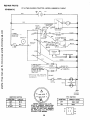
Wiling (Schematic)
..............
3
29
A SSEMBL Y
Know
Your Tractor
READ THIS OWNER'S
MANUAL
BEFORE OPERATING
YOUR GARDEN
TRACTOR.
If you understand the machine
and its operation,
you will achieve
efficient
and peak performance.
While reading
the manual,
compare
the illustrations
with your Garden Tractor
to familiarize
yourself
with the location of various controls
and adjustments.
Study the operating
instructions
and safety
precautions
thoroughly
to insure proper
functioning
of your Garden
Tractor
and to prevent
injury
to yourself
and others.
Be sure to pay strict attention
to all notes and cautions;
they are included
for your safety. Save this manual
for future
reference.
another free manual from www.searstractormanuals.com
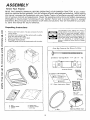
Unpacking
1,
Instructions
3.
Remove. box from carton. The box contains the/terns
shown below.
Cut down four corners of the carton with a utility
knife and fold down sides.
Remove mower
deck from skid.
4.
5.
Oisengage
Parking Brake.
Carefully guide the tractor
2.
backwards
The operation
of any tractor
can result in
foreign objects thrown i#to the eyes, which
can result in severe eye damage.
Always
wear safety glasses or eye shields before
starting
your tractor and while mowing.
We
recommend
Wide Vision
Safety
Mask for
over
the spectacles
or standard
safety
glasses, available at Sears Retail or Catalog
Stores.
off the skid.
Parts
Bag Contents
Not
Shown
"¢_l_llwJlll
(2)
Battery
Carriage
Bolts
- 1/4
Full Size:
K
'
'
- 20
x
7 - 1/2
C.
Terminal
Guard
(2) Keys
15 0 Slope
Instruction
Sheet
BA T FERY
CAPS &
iNSTRUCTIONS
e.
a,
b.
c.
seat
steering
battery
wheel
d. battery
acid
e. owner's
manual
f. parts ba9
V-Belt
Steering
Wheel
Cap
ASSEMBL Y
another free manual from www.searstractormanuals.com
A SSEMBL Y
LOCA "lION
PARTS
BAG
CONTENTS
SHOWN
FULL
SIZE
BA TTERY
(2) Lockwasher,
(2) Hex Bolt,
BATTERY
TERMINALS
1/4 Int/Ext
I/4-20x
(2) Wing Nut - 1/4 - 20
3/4
©
(2) Lockwasher
Tooth
(2) Washer
9/32
x 5/8 x 16 Ga.
Q
(2) Hex Nut,
1/4
1/4 - 20
SUSPENSION
ARMS
(4) Spring
Retainer
(4) Washer
17/32x
1 - !/16x
13 Ga.
SEA T
(I)
Hex Bolt, 1/2 - 13 x I
Grade 5
(J) Lockwasher
1/2
(1) Washer 17/32 x I-3/16
x 12 Ga.
(1) Shoulder
Bolt 5/16 - 18
(1) Washer
15/32x
i x 16 Ga.
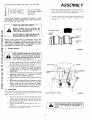
To assemble
II
(2)
and adjust
7/!6-
(1) 3/4""
(!) 9/16""
your
wrenches
wrench
wrenches
tractor
(2)
you
ASSEIVIBL Y
wil! need:
1/2"
wrenches
Tire Pressure
Screwdriver
Utility Knife
d,
Gauge
To adjust" Raise
seat to desired
securely.
NOTE: RIGHT HAND IR.H.)AND
LEFT HAND (L.H.)ARE
DETERMINED
FROM OPERATOR'S
POSITION WHILE
SEATED ON THE TRACTOR.
another free manual from www.searstractormanuals.com
WEAR
Place seat in operating
position.
Sit on the seat and
press clutch/brake
pedal all the way down. if oper
atlng position
is not comfortable,
adjust seat
seat. Loosen adjustment
bolt
position,
Tl_qhten adjustment
EYE AND FACE SHIELD.
MEDIATELY IF ACCIDENTALLY
IN CONWASH
HANDS
OR CLOTHING
IMTACT WITH
ELECTROLYTE.
DO NOT SMOKE, FUMES FROM CHARGED ELECTROLYTE ARE EXPLOSIVE.
VENT
CAP
CUT AWAY VIEW
LIQUID
LEVEL
BATTERY
TUBE
NOTE:
THIS
TRACTOR
IS EQUIPPED
WITH
AN
OPERATOR
PRESENCE SENSING SWITCH,
ANY ATTEMPT BY THE OPERATOR TO LEAVE THE SEAT WITH
THE ENGINE RUNNING AND ATTACHMENT
CLUTCH
ENGAGED WILL SHUT OFF THE ENGINE.
1.
Slide
belt
BATTERY
CELL
Prepare Battery
FIGURE
1
READ
INSTRUCTIONS
INCLUDED
WITH
THE BATTERYVENT
CAPS FOUND
IN BAG
OF PARTS.
ALWAYS
WEAR
GLOVES.
CLOTHING
AND GOGGLES
TO PROTECT
YOUR HANDS,
SKIN AND EYES.
a.
b.
c.
d.
e,
2.
Fill and charge battery (before installing). NOTE:
SEE DETAILED INSTRUCTIONS PACKAGED WITH
BATTERY VENT CAPS IN BAG OF PARTS.
Fill battery with electrolyte
to bottoms of tubes
in cells (Fig. 1). NOTE: DO NOT OVERFILL.
OVERFILLING
WILL RESULT IN DAMAGE
TO
TRACTOR.
Check level of electrolyte
after 30 minutes. Add
additional
electrolyte
if necessary.
NOTE:
TIGHTEN VENT CAPS SECURELY.
Charge battery at a rate of six amperes for one
hour.
Neutralize excess electrolyte
for disposal by adding it to four inches of water in a five gallon
plastic container.
Stir with a wooden or plastic
paddle while adding baking soda until the addition of more soda causes no more foaming.
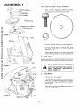
Install
Seat
Seat position should be adjusted
forward
or backward
so that
the operator
can comfortably
reach Clutch/Brake
Pedal and
safely operate the tractor (Fig 2).
a.
b.
c.
Place seat on seat pan. Screw hex head bolt, lockwasher
and flat washer
into seat (Fig 2). Screw
shoulder
bolt and flat washer into seat (Fig 2), Hex
bolt, shoulder
bolt and washers found in bag of parts
(shown full size page 5),
Tighten shoulder
bolt and flat washer usmg a 1/2""
wrench.
Tighten
hex bolt (adjustment
bolt), /ockwasher
and
flat washer using a 3/4"" wrench.
SEAT
PAN
SHOULDER
BOLT
ADJUSTMENT
BOLT
i
FUEL
TANK
CAP
!
/
/
CLUTCH/BRAKE
(
PEDAL
FIGURE
THE
MACHINE
SCREW-LOCKWASHERFLAT WASHER
MUST BE TIGHTENED
CURELY
TO PREVENT
MOVEMENT
SEAT.
SEOF
2
ASSEMBL Y
3.
Install
NOTE:
STEERING
WHEEL
CAP
Steering
POSITION
Wheel
FRONT WHEELS
FORWARD,
a.
Use a 9/16"
wrench to remove
hex bolt,
Iockwasher and 2-3/8" diameter washer (shown
full size below) from steering shaft (Fig, 3)
b.
Position
c.
Secure steering
wheel
hex bolt, Iockwasher
washer (Fig. 3).
HEX BOLT
LOCKWASHER
2 - 318"
DIA.
WASHER
another free manual from www.searstractormanuals.com
STEERING
---
FIGURE
WHEEL
STEERING WHEEL ADAPTER
STEERING
SHAFT
3
HOOD
BATTERY
COMPARTMENT
steering
wheel
over
steering
adaptor.
to steering shaft using
and 2=3/8""
diameter
d. Snap steering
wheel cap in place on steering
wheel. Steering wheel cap found in bag of parts.
4.
Check
Tires
Reduce tire.pressure to 14 PSI in front and 10 PSI in rear
tires, (Tires were overinflated
for shipping purposes).
GRILL
DO NOT SHORT
BATTERY
TERMINALS.
FIGURE 4
BEFORE INSTALLING BATTERY, REMOVE
METAL
BRACELETS,
WRISTWATCH
BANDS, RINGS, ETC.
NUT
ER
WASHER
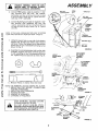
5.
Install Battery
a.
Remove
hood
- See page
23.
b.
Remove tape from plastic tray. Make sure drain
tube (Fig. 5) is fastened to drain hole in battery
tray and battery tray is positioned
in hole of battery support.
LOCKWASHER
HEX
BOLTS
BLACK
(NEGATIVE)
CABLE
FIGURE
5
DRAIN
TUBE
c . Place battery in plastic tray (Battery
front of tractor)(Fig.
5).
terminals
to
NECTED FIRST TO PREVENT SPARKS
POSITIVE
TERMINAL GROUNDING.
MUST
BE CONFROM ACCIDENTAL
d,
e,
Connect RED battery cable to positive (+) battery
terminal
with
hex bolt,
flat
washer,
Iockwasher and hex nut (shown full size on page
6) found in bag of parts (Fig. 6). Tighten securely,
with two 7/16"
wrenches.
Connect
BLACK
ground
cable to negative
(-) battery
terminal
with
remaining
hex
bolt,
flat
washer,
Iockwasher
and hex nut (shown
full size
on page 5) found in bag of parts (Fig. 6). Tighten
securely.
ASSEMBL Y
1
INT./EXT.
LOCKWASHER
WING
NUT
/
WING NUT
,,_
INT./EXT.
\
LOCKWASHER
),L
ACCESS
DOOR
,L
another free manual from www.searstractormanuals.com
GUARD
NOTE: IF YOU HAVE A WEAK BATTERY,
SEE "STARTING
YOUR TRACTOR
WITH AWEAK
BATTERY"
PAGE 19.
f.
TERMINAL
ACCESS
DOOR
Using the square hole on one side of the battery
support (Fig. 6) insert one battery bolt, head of
bolt down. Fasten the battery bolt to the terminal
guard using int./ext. Iockwasher
and wing nut as
shown in Fig. 6.
BOLT
BATTERY
SUPPORT
FIGURE
g°
Assemble the remaining battery bolt to other side
of battery support and fasten terminal guard to
it with remaining int./ext.
Iockwasher
and wing
nut. Tighten wing nuts securely by hand (Fig. 6).
6
ATTACHMENT
LIFT LEVER
"HIGHEST'"
POSITION
HEIGHT
ADJUSTMENT
KNOB
r i_
ATTACHMENT
LIFT LEVER
"'LOWEST'"
POSITION
....
0
ARM
h.
Remove
Plastic
on tractor
hood
y
and close
RELEASE
NOTE: USE TERMINAL ACCESS DOORS (FIG. 6) FOR:
1 INSPECTION
FOR SECURE
CONNECTIONS
(TIGHTEN HARDWARE)
2 INSPECTION
FOR CORROSION
3 TESTING BATTERY
4 JUMPING
(IF REQUIRED)
5 CHARGING (IF REQUIRED)
FRONT
SUSPENSION
BRACKET
FIGURE
7
RETAINER
SPRING
KEEP TERMINAL
ACCESS
DOORS
CLOSED WHEN NOT IN USE.
DO
NOT
START
ENGINE
UNTIL
MOWER SUSPENSION
BRACKET HAS
BEEN RELEASED.
SEE MOWER DRIVE
BELT INSTALLATION,
PAGE 10.
BRACKET
SUSPENSION
ARM
LIFT LINK
STUD
RETAINER
SPRING
FIGURE
9
8
A
Y
6.
MOWER DRIVE
BELT
PRIMARY
MANDREL
Mower
a.
b .
c.
FRONT
SUSPENSION
BRACKET
d.
e.
f.
g.
h.
another free manual from www.searstractormanuals.com
FIGURE 9
WHEEL
GAUGE/
BAR
I.
GAUGE
WHEEL
7.
\
Installation
Remove band from mower suspension
bracket.
Remove banding from suspension arms (Fig. 7),
Slide mower under tractor,
deflector
to R.H.
side.
Slide front suspension
brackets
into mower
brackets.
Retain with release pins (Fig. 7).
Turn depth adjustment
knob counterclockwise
( _
) until it stops.
Push attachment
lift lever forward
to lower
mower to ground (page 11),
Slide studs through lift links on both sides of
tractor
(Fig. 8). Retain with washers
and retainer springs found in bag of parts.
Place the suspension arms on brackets on both
sides of frame (Fig. 8). Retain with washers and
retainer springs found in bag of parts,
Turn height adjustment
knob (Fig. 7) clockwise
(
_
) to remove
slack
from
mower
suspension.
Roll drive belt over primary mandrel
(Fig. 9).
Mower
Drive Belt Installation
BRACKET
a.
b.
FIGURE
10/I
Remove hood and grill (See page 23).
Place mower drive belt over clutch pulley, and
under idler pulley and tension pulley (Fig, 11).
NOTE: PULL LEVER UP TO SWING TENSION
PULLEY FOR BELT CLEARANCE.
Make sure
narrow
"'V'" side of belt is engaged in each
pulley.
c . Putl mower drive belt over front mower suspension bracket (Fig. 9).
d. Replace hood and grill.
_CLEVIS
PIN
CLUTCH
PULLEY
8.
MOWER
DRIVE
BELT
a.
b.
c.
d.
IDLER
LEVER
Mower
TENSION
PULLEY
e.
_GURE
f.
11
9.
Drive Belt Adjustment
Lower mower using attachment
lift lever.
If dimension
"A'" on idler bracket
assembly
measures
!/4"" or less, mower drive belt must
be adjusted (Fig. 1 I-Inset).
Disengage attachment
clutch switch.
Using two 9/16"
wrenches,
remove bolt, (2)
washers, Iockwasher
and nut from idler pulley
(Fig. 1 l-Inset)
(original position).
Place v-belt and idler pulley in "'NEW" pulley
position
(Fig.
1 I-Inset).
Replace
bolt,
(2)
washers, Iockwasher and nut, Tighten securely.
Check v-belt for proper installation
on all pulley
grooves.
Check the Cutting
Level
The blade housing was set at the factory to cut level.
After mowing a short distance, look at the area that was
cut. If the blade housing cuts uneven; see the instructions on "'Side-to-Side
And Front-to Rear Mower Adjustment"
(page 24)".
10. Final Assembly
a.
b.
IDLER
BRACKET
c.
PULL FORWARD
TO LOOSEN BELT
FOR EASIER BELT
INSTALLATION
!O
Make sure all fasteners are tight.
Read and follow
the operation
instructions
(page 1 !). Know the location and purpose of
all controls.
Check oil and gasoline before starting
the tractor.
OPERA TION
KNOW
YOUR
TRACTOR
another free manual from www.searstractormanuals.com
READ THIS OWNER'S MANUAL BEFORE OPERATING YOUR GARDEN TRACTOR.
If you understand
the machine and
its operation,
you will achieve efficient and peak performance.
While reading the manual, compare the illustrations
with
you Garden Tractor to familiarize
yourself with the location of various controls and adjustments.
Study the operating
instructions and safety precautions
thoroughly
to insure proper functioning
of your Garden Tractor and to prevent injury to yourself and others. Be sure to pay strict attention
to all notes and cautions;
they are included
for your safety.
Save this manual for future reference.
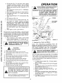
Light
Arnmeter
Switch
A ttachment
Clutch
Switch
Attachment
Lift Lever
Clutch/Brake
Pedal
.Choke
,ttle
Height
Adjustment
Knob
Gear
Shift
Parking
Lever
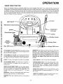
ATTACHMENT
up to engage
tion
as the
CLUTCH
attachment.
clutch
SWITCH:
Pull
There
be an engine
will
switch
out
engages.
To start a cold engine, pull choke out to engage.
LIGHT
Place key in ignition
SWITCH:
Turns on and off
PARKING BRAKE LOCK: To set the
the clutch/brake
pedal completely
parking brake lever in "Engaged"
pressure from pedal. Clutch/brake
brake position.
HEIGHT ADJUSTMENT
KNOB: Use the height adjustment knob to adjust the mower height. With attachment
lift lever in the full "'UP" position,
turn clockwise
( F_.)
to raise mower and counterclockwise
(/f_)
to lower
mower.
GEARSHIFT: Press the clutch/brake
pedal down
and move gear shift lever to desired speed.
Lever
AMMETER:
Each time you start your tractor, check your
ammeter.
The needle should move
towards
the (+)
charging mark indicating the battery is being charged as
you operate the tractor.
The headlights
will not show a
discharge on the ammeter because they are not connected to the battery
(they have their own electrical
source).
and
hesita-
CLUTCH/BRAKE
PEDAL: The pedal has 2 functions:
a
clutch and a brake. To engage
push the pedal completely down.
IGNITION:
start.
Brake
,ge Shift
A TTACHMENT LIFT LEVER: Use the attachment lift lever
to raise and lower the attachment
mounted to your tractor. Move the lift lever forward to lower attachment.
CHOKE:
Control
the headlights.
parking brake, push
forward. Place the
position and release
pedal will remain in
RANGE SHIFT LEVER: The Hi-Lo range shift lever gives
you the versatility
of 6 speed selections:
Lo 1, 2, 3, and
Hil,
2,3.
firmly
and turn to the right
THROTTLE CONTROL: Use the throttle control
crease or decrease the speed of the engine.
to
11
to in-
OPERA TI ON
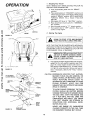
1. Stopping
NOTE: REMOVE KEY WHEN LEAVING
PREVENT UNAUTHORIZED
USE.
a.
b.
c.
d.
e.
f.
another free manual from www.searstractormanuals.com
Your Tractor
TRACTOR
TO
Push clutch/brake
pedal into full "'BRAKE'"
position.
Place parking brake in "ENGAGED"
position and
release pressure from clutch/brake.
Pedal should
remain in "BRAKE"
position. NOTE: MAKE SURE
PARKING
BRAKE
WILL
HOLD
TRACTOR
SECURE.
Move gear shift lever to "NEUTRAL"
position.
Place attachment
clutch switch in "DISENGAGED" position.
Move throttle control to "'S'" (slow) position.
Turn ignition key to "OFF" position.
Never use
choke to stop engine.
DIPSTICK
2.
ENGINE
Starting
The Engine
FIGURE 12
PAP,
SEAT
YOURTRACTORIN
LARGE,
OPEN
AREA.
LEARN TO START, ASTOP
AND
REVERSE
_
NOTE: THIS TRACTOR IS EQUIPPED WITH INTERLOCK
SWITCHES TO PREVENT STARTING OF THE TRACTOR
ENGINE WHILE THE ATTACHMENT CLUTCH OR THE
CLUTCH/BRAKE PEDAL IS ENGAGED.
IMMEDIATELY REPLACE SWITCHES THAT
ARE NOT IN PROPER WORKING ORDER.
DO NOT ATTEMPT TO DEFEAT THE PURPOSE OF THESE SWITCHES.
\
a. This engine has been shipped filled with summer
weight oil (for cold weather operation see Chart
page 16). Check engine oil level with tractor on
level ground. Wipe dipstick (Fig. !2) clean, screw
it in tight for a few seconds, remove and read oil
level. If necessary, add oil until "FULL'" mark is
reached.
/
CLUTCH
FIGURE
BRAKE
PEDAL
13
A AO.M.NT
CAUTION:
CLUTCH
SWI;CH
,O.,T.O.
,-
"-L. !/"°_d_
V/
T.ROTTLE
CONTROL
LOWE%. Z_--J c.oK.
ADJUSTMENT
\"S_,,_r_r
..... -_------_)..Jl
N.F
,_//X_
",_,_;._
/
_'
___
/
GEAR
FIGURE 14
TO AVOID ENGINE PROBLEMS, THE FUEL
SYSTEM SHOULD BE EMPTIED BEFORE
STORAGE FOR 30 DAYS OR LONGER. DRAIN
THE GAS TANK, START THE ENGINE AND
LET IT RUN UNTIL THE FUEL LINES AND
CARBURETOR ARE EMPTY. USE FRESH
FUEL NEXT SEASON. SEE STORAGE INSTRUCTIONS
FOR ADDITIONAL
INFORMATION. (PAG E 26).
.....
,'_ "\,
\_
_
PARKING
BRAKE
s HIFT
\
EXPERIENCE INDICATES THAT ALCOHOL
BLENDED FUELS (CALLED GASOHOL OR
USING ETHANOL OR METHANOL) CAN ATTRACT
MOISTURE
WHICH
LEADS TO
SEPARATION AND FORMATION OF ACIDS
DURING
STORAGE.
ACIDIC GAS CAN
DAMAGE THE FUEL SYSTEM OF AN ENGINE
WHILE IN STORAGE.
LEVER
NEVER USE ENGINE OR CARBURETOR
CLEANER PRODUCTS IN THE FUEL TANK
OR PERMANENT DAMAGE MAY OCCUR.
SHIFT
CONTROLLEVER
12
TION
b.
Fill fuel tank (Fig. 13). Use fresh, clean, regular
unleaded automotive
gasoline.
(Use of leaded
gasoline
will increase
carbon
and lead oxide
deposits and reduce valve life). Capacity is 3- 1/2
gallons,
c. Place attachment
clutch switch in "'DISENGAGED" position,
d. Push clutch/brake
pedal fully into brake position,
e. Place gear shift
tion (Fig. 14).
start
posi-
f . Place range shift lever in "N'" neutral position
14).
(Fig.
g.
Pull choke
another free manual from www.searstractormanuals.com
h . Move
lever in "'N'" neutral,
out (Fig.
throttle
control
to middle position
DEPTH
After
ATTACHMENT
LIFT LEVER
in.
The first time you start the engine, it will take extra
cranking time to move fuel from tank to engine. NOTE:
ALLOW ENGINE TO WARM UP FOR A FEW MINUTES
BEFORE ENGAGING CLUTCH/BRAKE
PEDAL OR ATTACHMENT
CLUTCH SWITCH.
k.
_: RETAINER
SPRING
When restarting
a warm engine, move throttle
control midway
between
"'S'" (slow) and "'F'"
(fast) position.
Choke may not have to be used.
CLEVIS PIN
GAUGE
3.
I
,_
7 .
2.
3.
4.
5.
6.
7.
8.
9.
10.
lf.
PLUNGER
(Fig, 14).
j.
push choke
DO NOT ADD ADDITIONAL
WEIGHT
TO THE TRACTOR OTHER THAN THE
OPTIONAL
WHEEL
WEIGHTS.
EXCESSIVE WEIGHT
MAY
OVERLOAD
AND DAMAGE THE TRANSMISSION.
ADJUSTMENT
KNOB
Turn ignition to "START"
position
until engine
starts (Fig. 14). NOTE: DO NOT RUN STARTER
CONTINUOUSLY
FOR MORE THAN
FIFTEEN
SECONDS PER MINUTE. If engine does not start
after several attempts,
move throttle control to
"'F'" (fast) position,
wait a few minutes and try
again.
is warm,
IMPORTANT:
14),
i.
engine
THE
DEFLECTOR
IN PLACE.
DO NOT
OPERATE SHIELD
THE MOWER
WITHOUT
MOWER
OR REMOVE
FRONT
BEFORE DRIVING
THE(FIG.
TRACTOR,
SUSPENSION
ARM
8,.
MOWER
INSTALL
WHEEL
Operating
FIGURE
15
_--
Your Tractor and Mower
NOTE:
THIS
TRACTOR
IS EQUIPPED
WITH
AN
OPERATOR PRESENCE SENSING SWITCH.
ANY ATTEMPT BY THE OPERATOR TO LEAVE THE SEAT WITH
THE ENGINE RUNNING
AND
THE ATTACHMENT
CLUTCH ENGAGED WILL SHUT OFF THE ENGINE.
TO CAUTION
AVOID INJURY
Read owner's
manual.
Know location and function of all controls.
Keep guards, safety shield and switches
in place
and working.
Remove objects that can be thrown by blades.
Do not mow when children and others are around.
Never carry children or passengers.
Always look behind machine before backing.
Do not mow where machine can tip or slip.
If machine stops going uphill, stop blades and back
slowly down.
Be sure blades end engine have stopped before
placing hands or feet near the blades.
Remove key when leaving machine.
BEFORE
OPERATING
READ THE
"SAFETY
YOUR MOWER.
RULES"
CAREFULLY
Use the height
adjustment
knob (Fig. 14) to adjust
mower height. With the attachment
lift lever in the full
"'UP" position,
turn height adjustment
knob clockwise
("-_) to raise cutting height and counterclockwise
(_-_)
to lower cutting height. Lower attachment
lift lever to
check adjustment.
a.
b.
c.
ii-,llli.i
NEVER PLACE YOUR HANDS
OR FEET IN
OR UNDER ANY POWERED ATTACHMENT
OR NEAR ANY
MOVING
PART WHILE
TRACTOR
OR ANY POWERED
ATTACHMENT IS RUNNING.
d.
e.
DO NOT OPERATE THE MOWER WITHOUT
THE DEFLECTOR
SHIELD IN PLACE,
g.
f.
13
To adjust gauge wheels (Fig. 15) lower attachment lift lever,
Remove retainer spring and clevis pin from gauge
wheels.
Move gauge wheels to the adjustment
hole that
will provide the desired cut.
Replace retainer spring and clevis pin.
Move attachment
lift lever to its full "'UP"
position.
With engine running and warm, place throttle control midway between
"S'" (slow) and "'F'" (fast)
position
(Fig. 14).
To engage mower pull attachment
clutch switch
(Fig. 14) out and up.
OPERA TiON
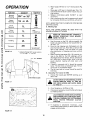
FUNCTION
Normal
Mowing
2H*
Heavy
Mowing
1H
Snow
another free manual from www.searstractormanuals.com
C
I
GEARSHIFT
THROTTLE
or 3L*
or 2L
Removal
1L
Tilling
Plowing
1L
Dozing
1L
Grading
2L
Transport
3H
h . Move range shift lever to "'LO'" (low) postion (Fig.
14).
i. Move gear shift lever to desired gear (Fig. 14).
j.
Use attachment
rift lever to lower mower into cutting position.
k. Release clutch/brake
pedal SLOWLY
to start
movement.
I. Start mowing at slow and increase ground speed
by increasing
throttle as conditions
will permit.
NOTE: BRING TRACTOR
SHIFTING GEARS.
5.
16
*
BE USED
THE
a.
Use the runner on the R.H. side as a guide; the
blade cuts approximately
an inch outside the runner (Fig. 17).
b. Drive so that clippings are discharged
onto the
area that has been cut. Have the cut area to the
right of the machine.
This will result in a more
even distribution
of clippings and more uniform
cutting.
c. When mowing large areas (Fig. 18), start by turning to the right so that the clippings
will be
discharged away from shrubs, fences, driveways,
etc. After two or three rounds, mow in the opposite
direction
making
left hand turns until
finished.
d. If grass is extremely
tall, it should be mowed
twice. The first time cut relatively high. The second time to the desired height.
e. The left hand side of mower should be used for
trimming.
Indicates
Range Shift Lever position:
"H" for High. "L" for low
RUNNER
5.
Li
Operating
a.
DISCHARGE
The Tractor
Choose the lowest
down hills.
On Hills
gear BEFORE starting
up or
GUARD
DO NOT DRIVE UP OR DOWN HILLS WITH
SLOPES GREATER THAN
15 ° AND DO
NOT DRIVE ACROSS ANY SLOPE, REFER
TO PAGE 51.
17
b. Avoid stopping or shifting on hills.
c . If slowing is necessary, move throttle
to middle position.
.....
'
WITH
READ THE "SAFETY RULES" CAREFULLY
BEFORE OPERATING
YOUR
MOWER.
REFER TO PAGE 2.
R.H.
_GURE
STOP BEFORE
Tips
NOTE: TIRE CHAINS CANNOT
MOWER HOUSING ATTACHED
MID
THROTTLE
SLOW-FAST
FIGURE
Mowing
TO COMPLETE
_,
control lever
LEAVE ENOUGH ROOM WHEN STOPPING
AND STARTING TO ALLOW SLIGHT TRACTOR ROLL DOWNHILL AS CLUTCH/BRAKE
PEDAL
MOVES
THROUGH
CLUTCH
POSITION.
!t!
,lil
Jj
d.
FIGURE 18
14
If stopping
is absolutely
necessary,
push
clutch/brake
pedal quickly to brake position and
engage parking brake.
I
I
e.
To restart your tractor, make sure tractor is in 1st
gear and that you have allowed room to roll slightly downhill. Disengage parking brake and release
clutch/brake
pedal SLOWLY to start tractor forward movement.
f.
Make
all turns
MAINTENANCE
slowly.
\
another free manual from www.searstractormanuals.com
To keep your tractor running better,
longer, perform necessary
service using
the following maintenance
schedule:
BEFORE MAKING ANY INSPECTION,
ADJUSTMENT
OR REPAIR: (FIG. 19):
1. PUSH TRACTOR CLUTCH/BRAKE
PEDAL COMPLETELY INTO BRAKE
POSITION.
2. MOVE
GEAR SHIFT
CONTROL
LEVER TO NEUTRAL POSTION.
3. PLACE
PARKING
BRAKE
IN
"ENGAGED"
POSITION :AND REMOVE
FOOT FROM PEDAL,
4. TURN
OFF
ATTACHMENT
L,H.
SIDE
PANEL_
FIGURE 19
5. CLUTCH
SHUT OFFSWITCH.
THE ENGINE.
6. MAKE ABSOLUTELY
SURE THE
BLADES AND ALL MOVING PARTS
HAVE COMPLETELY
STOPPED.
7. DISCONNECT
THE SPARK PLUG
WIRES FROM THE SPARK PLUGS
AND KEEP WIRES AWAY FROM
THE SPARK PLUGS TO PREVENT
INJURY
FROM
ACCIDENTAL
STARTING.
BE CAREFUL
TO
AVOID TOUCHING
HOT ENGINE
OR MUFFLER COMPONENTS.
With
Every
Make sure all nuts on bolts are tight and cotter
and retainer springs are secure.
2.
Observe
all safety
(Two
L.H. SIDE
. ....
_
pins
precautions.
3. Keep tractor _vell lubricated
2 Hours
OIL
DIPSTICK
AND
FILL TUBE
Mowing
I.
First
ENGINE
(refer to page !8).
Mowings)
t
1. Change Engine
Oil
Changing off after the first two hours (or two mowings) will help eliminate break-in residue which might
be damaging
to your engine.
NOTE: BE CAREFUL NOT TO ALLOW DIRT TO ENTER
THE ENGINE WHEN CHANGING
OIL.
FIGURE
a. Drain oil with engine warm.
b. Remove hood and grill (see page 23).
c. Loosen oil drain wing nut (Fig. 20 - Inset).
Catch oil in a suitable
container.
d. Tighten oil drain wing nut after all oil has been
removed
from engine.
e. Refill engine oil. Refill capacity is 3 pints.
NOTE: DO NOT OVERFILL.
f. Replace dipstick.
15
20
MAINTENANCE
Recommended
SAE
Viscosity
Grades
Determine temperature expected before next oft change.
All oft must meet A.P.I. service classification
SD, SE or
SF.
SHIFT
COVER
_20 o
0o
32 °
60 °
80 °
100 °
30 or lOW-30
I
another free manual from www.searstractormanuals.com
\
_;_
IF]
Capacity is 3pints.
NOTE: DO NOT OVERFILL. Dipstick
assembly
must be securely
tightened
into tube at all
times when engine is operating.
IMPORTANT:
f
FIGURE 21
Replace
Every
1.
G
"
dipstick.
5 Hours
Check
Engine
NOTE:
D
TO AVOID DAMAGE TO THE STAR"rING SYSTEM, USE SAE 5W30
OIL
WHEN
THE TEMPERATURE
FALLS
BELOW 32 ° .
E
(l_ve
Mowings)
Oil Level
DO NOT CHECK ENGINE
WITH ENGINE RUNNING.
OIL LEVEL
Several minutes after stopping engine, check engine oft
level with tractor on level ground. Wipe dipstick (Fig. 20)
clean, screw ff down tight for a few seconds, remove
and read oft level. If necessary, add oil until "FULL" mark
is reached.
NOTE: DO NOT OVERFILL.
Every
FIGURE 22
25 Hours
(Operating
in dusty
(Twice
conditions
a Mowing
may
require
Season)
more frequent
servicing.)
1. Brake
I
IF TRACTOR REQUIRES MORE THAN
SIX FEET STOPPING
DISTANCE
IN
HIGHEST
GEAR ON A LEVEL DRY
CONCRETE
OR PAVED
SURFACE
THEN BRAKE MUST BE ADJUSTED.
i
CENTER
_
HOLE
a . Remove (4) hex washer head tapping screws from
shift cover plate (Fig. 21), located on top of tractor frame. Remove the cover plate.
,,,oE) \
i
FIGURE
Adjustment
b. Loosen jam nut (G) on brake rod (B) at clevis (c)
(Fig. 22). If you find it difficult
to loosen jam nut
(G), remove cover plate in L.H. frame raft.
I
i
c. Rotate brake rod (B) counterclockwise
(,#-_) turning brake rod out of clevis (C) four to six turns.
23
d.
Start tractor
position.
with tramsmission
e . Depress clutch/brake
stops moving.
16
in "N'"
pedal to the point
(neutral)
where belt
MAINTENANCE
f . Engage parking brake to hold clutch/brake
pedal
in position. If belt begins to move after engaging
parking brake, depress clutch/brake
pedal to next
notch on parking brak e.
VENT
CUT AWAY VIEW
g. Shut engine off. Rotate brake rod (B) clockwise
(f-_) by hand, turning brake rod into clevis (C),
until tight. Tighten jam nut (G) on brake rod. (B)
at clevis (C) (Fig. 22).
CAP
LIQUID
LEVEL
BATTERY
h. Reinstall shift cover plate and four (4) mounting
screws. Replace cover plate if removed in step b.
2.
BATTERY
CELL
Tire Care
another free manual from www.searstractormanuals.com
Maintain
tire pressure
at 10 PSI,
3.
in front
at 14 PSI and rear tires
FIGURE
Blade Care
For best results mower blades must be kept sharp. The
blades can be sharpened with a few strokes of a file or
COVER
on a grinding wheel. We suggest they be sharpened after
every 25 hours of mowing,
Do not attempt
to sharpen
while on mower.
a.
b,
_=
Every
CARTRIDGE
PLATE
When grinding,
care should be taken to maintain blade balance and the blade should be
checked for proper balance before reinstallation
on mower.
Unbalanced
or bent blade will cause excessive
vibration when running and eventual damage to
mower
or engine.
Replace bent or damaged
blades.
50 Hours
(Operating
servicing)
Check
a.
NUT
WASHER
PAPER
CARTRIDGE
OIL FOAM
PRE-CLEANER
To check blade balance, drive a nail into a beam or wall.
Leave about one inch of the straight nail exposed. Place
center hole of clean blade over the head of the nail (Fig.
23). NOTE: CENTER HOLE OF BLADE ON NAIL. IF
BLADE IS PROPE[RLY BALANCED,
BLADE SHOULD REMAIN IN POSITION SHOWN iN FIG. 23. IF EITHER END
OF THE BLADE MOVES DOWNWARD,
BLADE IS NOT
BALANCED,
SHARPEN THE HEAVY END UNTIL THE
BLADE IS BALANCED.
1.
24
(Once
a Mowing
in dusty conditions
may require
BODY
FIGURE
2,
25
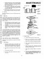
Clean Air Filter
a.
Unscrew
knob
(Fig. 25) to remove
cover.
b.
Remove nut and washer to remove cartridge
plate, paper cartridge and oil foam pre-cleaner.
c.
Wash foam pre-cleaner
in detergent
d.
Rinse, squeeze
throughly.
than twist)
Season)
more frequent
and water.
Battery
Electrolyte
solution
level in each battery
cell
should be even with bottoms
of tubes in cells
(Fig. 24). Add only distilled water if necessary,
NO-FE: DO NOT OVERFILL, DO NOT ADD ACID.
b . Keep battery
18.
and terminals
e.
Keep battery
bolts
d.
Keep vent caps
caps open.
allow
Lightly
coat with S.A.E. 30engine
saturate. Squeeze in a rag or towel
evenly and remove excess.
to dry
oil. Donot
to distribute
clean. Refer to page
f.
c.
(rather
Check
dirty.
paper
cartridge.
Replace
if excessively
tight.
g.
tight
and small
vent
holes in
17
Reassemble
paper cartridge and re-position
on
tractor.
NOTE: NEVER RUN ENGINE WITH AIR
FILTER REMOVED
AS DIRT (DUST)
WILL
DAMAGE
THE ENGINE.
MAINTENANCE
3.
Clean
Battery
and
4.
Terminals
Corrosion and dirt on the battery and terminals cause the
battery to "leak" power and hinders the operation of the
charger.
a. Remove terminal guard.
another free manual from www.searstractormanuals.com
c.
Remove the battery from the tractor and wash
with four tablespoons
of baking soda to one
gallon of water. NOTE: BE CAREFUL NOT TO
GET THE SODA SOLUTION
INTO THE CELLS.
Clean terminals
until
d.
a.
b.
c.
d.
e.
bright.
with
plain
water,
dry
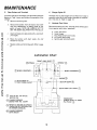
Lubricate
Pivot Points
Place several drops of S.A.E. 30 oil at points
move against each other, especially:
and cable ends with a wire brush
Rinse the battery
reinstall on tractor.
Engine Oil
The best time to drain engine oil is at the end of a day's
operation when all dirt and foreign materials are suspended in the hot oil. Refer to page t 5.
5.
b.
Change
and
where parts
Front Axle Pivot
Hood Hinges
Foot Pedal Shaft (both ends)
Lift Shaft (both ends)
Sector gear end pivot points
e . Replace cables and terminal guard. Refer to page
8.
Lubrication
Chart
i_
SPINDLE
@
SPINDLE
BEARINGS
@WHEEL
_
BEARINGS--_
ENGINE
BOTH
FOOT
ENDS
PEDAL OF
(SC, SD OR SE)
OIL
CHASSIS
GREASE
SEARS PART NO.
_
(_
SECTOR
--BOTH
SAE 30
MOTOR
GEAR
ENDS
LIFT
SHAFT@
TRANSAXLE
(CHECK
LEVEL
2557R
FILL
REFER TO ENGINE OIL SPEC'S.
(UNDER INITAL PREPARATION
IN OWNERS MANUAL)
CHASSIS GREASE
WITH BRUSH
18
@
WHEEL
PLUG)
@
AT
REAR
6.
MAIIVTENANCE
Clean Air Screen
Air screen (Fig. 26) must allow free-flow of air to prevent engine damage from overheating,
Clean with a wire
brush or compressed
air to remove dirt, stubborn dried
gum and fibers.
7.
HEAT
SHIELD
Clean Front Grill
Brush debris from front grill to allow free-flow
preventing
engine damage from overheating.
8.
another free manual from www.searstractormanuals.com
.,_
Lubricate
Steering and Front
MUFFLER
ENGINE
COOLING
FINS
of air,
i._L
Wheels
There are four grease fittings on your tractor (Fig. 27).
Using a grease gun, give each grease fitting two shots
of chassis grease (available through your Sears Service
Center).
Sears Part No. 2557R.
9.
AIR
SCREEN
AIR GUIDE
COVER
Figure
26
Check Muffler
Inspect and replace corroded muffler
a fire hazard and/or engine damage.
EVERY
100
HOURS
(Every
as it could create
Two
Years)
I
,,,¢_-, _
_1=
I
VENT ANY
ACCIDENTAL
STARTING
BEFORE MAK-_
ING
INSPECTION,
ADJUSTMENT
O1_
DISCONNECT
SPARK
PLUG WIRES TO PRE4
REPAIR (EXCEPT
CARBURETOR).
|
_-.
/
1.
Replace
Spark
""
.s.,r%_
."E-%A-T3_
__
Replace spark plugs at the beginning of each season or
every 1O0 hours, whichever
comes first. Gap should be
set at 0.030 inch (Fig. 28).
2.
_'_:_=m_'ll
/
Plugs
,,_-L:_I!
IN AREA
OF SECTOR
._"_
II
|_.__.- AXLE
F
F.ONT
SPINDLE
_FIi]
k_LEFT
_R'GHT_
P'_'I
y___
_ FRONT
WHEEL
Replace Air Filter Paper Cartridge
Refer
to page
7 7.
FIGURE 27
REPAIR AND
1.
Starting
Your Tractor
with
a Weak
ADJUSTMENT
Battery
If your battery is too low to start the engine, it should
be recharged, If "'jumper cables" are used for emergency starting
follow this procedure:
,030"
FEELER
GAUGE
NOTE: YOUR TRACTOR IS EQUIPPED WITH A 12 VOLT
NEGATIVE GROUNDED SYSTEM, THE OTHER VEHICLE
MUST ALSO BE A 12 VOLT NEGATWE
GROUNDED
SYSTEM.
LEAD-ACID
BATTERIES GENERATE
PLUG
FIGURE
EXPLOSIVE
MATERIALS
AWAY
FROM AND
BATTERIES,
GASES. KEEP SPARKS,
FLAME
SMOKING
ALWAYS
WEAR EYE PROTECTION
AROUND
BATTERY.
19
28
REPAIR AND ADJUSTMENT
a.
NEGATIVE
(BLACK CABLE)
TERMINAL
Connect
each end of the RED cable to the
POSITIVE (+) terminals of each battery (taking
care not to short against chassis).
(Fig. 29).
Connect
one end of the BLACK cable to the
NEGATIVE (-) terminal of fully charged battery.
Connect the other end of the cable to L.H. side
penel bolt (Fig. 19). NOTE: KEEPAWAY
FROM
GAS TANK AND BATTERY.
Disconnect
cables in reverse order:
1. L.H. Side Panel Bolt (Fig. 19),
2. Negative
Terminal of fully' charged Battery
3. Postive Terminals
b,
c.
d.
another free manual from www.searstractormanuals.com
BATTERY
CAUTION:
2.
POSITIVE
IRED CABLE)
TERMINAL
FIGURE
DO NOT USE YOUR BATTERY
START OTHER VEHICLES.
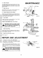
THROTTLE
CONTROL
CABLE
TO
ADJUSTMENTS
Never attempt
to change maximum
engine speed. This is
preset at the factory (3400
.*_ 100RPM)
and should only
be change by a qualified
service technician
who has the
necessary
equipment.
a
Remove hood, page 23.
b. Loosen casing clamp screw until throttle
cable is free
to move
c
Move throttle
control
(on the dash board) to "Fast"
29
posLhon
Pu!l throttle
quartercircei
d
cable tight tantil swivel
_s agapnst side of
Fig. 30 Retighten casing clamp screw.
REFER TO
PAGE 12.
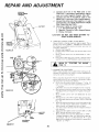
3
CARBURETOR
NOTE:
throttle
when
Air
running
ENGINE",
carburetor
adjustments
in fuel,
mixture
a
mixture
Gently
cable
turn
idle
closes
.
CAUTION:
making
must
any
ad-
be asserobied
may
Valvernay
be required
temperature
as follows:
valve
and
to
clockwise
then
Start
engine
and allow
final adiustments
with
ed in.
c
Move
to cornpen
or altitude.
Adjust
("-_)
Fig
counterclockwise
be damaged
b.
throttle
before
cleaner
engbne.
sate for differences
the carburetor
fuel
until
it iust
1 1/2 turns
FIGURE 30
control
to carburetor
carDuretor
Minor
THE
ADJUSTMENT
Adiust
lustment
"STARTING
if turned
in too
to warm
for five minutes.
engine
runnbng
and choke
control
lever
(on
31
(_'-'_)
dashboard)
to
far
Make
pushslow
posit_on.
d,
Hold governor
control
and adjust
idle speed
Fig,
e
still holding
the governor
turn idle mixture
valve
mixture)
Turn idle mixture
rich and lean.
g.
Adjust
f.
RPM,
Move
engine
"SLOW"
FIGURE 31
20
until
f.
the
wi!l
speed
vatve
idle
ReFease
throttle
If engine
proximately
URE
against
to obtain
idle speed
screw,
1200
to1400
RPM.
31.
While
stop,
(lean
lever
screw
speed
governor
control
hesitates
1/8
control
slowly
just
back
starts
to the
screw
lever against
id)e
clockwise
!r-_)
to slow.
midpoint
to obtain
control
lever.
(on the dashboard)
between
900
to
to
1200
"FAST".
or dies.
turn idle mixture
valve
apturn
counterclockwise
(-J'_"_) until
accelerate
to "FAST",
as throttle
control
is moved
from
AND ADJUSTII4ENT
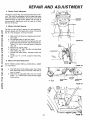
4.
Electric
Clutch Adjustment
The electric clutch (Fig. 32) should provide years of service. The clutch incorporates
a built-in brake that stops
the pulley almost immediately.
Eventually,
the internal
brake will wear so the mower blades will not stop as
recommended,
Adjustment
must be made by a Sears
Service Technician.
another free manual from www.searstractormanuals.com
5.
Motion
ELECTRIC
Drive Belt Ren_oval
The belt on this tractor is special for this application.
Always replace with the Sears belt number in the parts
![st. It is not necessary to remove mower.
a.
b,
c.
d.
e,
f,
g,
6.
Raise hood and disconnect negative ground battery cable.
Set parking brake (to get belt slack).
Loosen (do not remove) two engine pulley belt
guide bolts and swivel R,H. side of belt guide up.
Tighten L.H. bolt to hold belt guide in position
(Fig. 33).
Roll belt off engine pulley,
Roll belt off "'V'" idler, flat idler and adjustable
idler pulleys (Fig. 34).
Pull belt off clutch pulley - between pulley and
frame.
Loosen nut "'A'" on R.H. outside of frame (Fig.
35),
Motion
FIGURE 32
LOOSENBO'T---1111 ,
Drive Belt Replacement
NOTE: THERE IS A BELT iNSTALLATION
L.H. FOOTREST.
PULLEY
DECAL UNDER
_
--
FIGURE
a.
Push belt down from engine pulley area. Place
back (flat) side of belt on flat idler. (Flat idler is
next to frame).
b. Place belt on adjustable
idler and over clutch
pulley. "'V'" (narrow) part of belt should engage
clutch pulley.
33
(C )F
ADJUSTABLE
"V"
IDLER
PULLEY
IDLER
TRANSAXLE
PULLEY
SHIFT
COVER
I
PLATE
I
FIGURE
34
F_U_
35
\
,
21
REPAIR AND ADJUSTMENT
c. Place belt around
transaxle
pulley.
"V"
part of
0
d. Make
NE PULLEY
_i
BELT
_
e.
_
Release parking brake. NO'rE: WHEN A NEW
BELT HAS BEEN INSTALLED,
YOU MUST
CHECK V-BELT ADJUSTMENT
AND BRAKE
ADJUSTMENT.
another free manual from www.searstractormanuals.com
©,_
FIGURE 36
h.
J
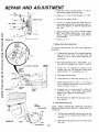
7.
Tighten
Motion
To assure
seasonally.
TOP OF
FRAME
a.
,_- 1116""
TOP
PIN
OF
1
1/16""
_.
FIGURE 37
NUT
CLUTCH
IDLER
"'A "'_
Drive Belt Adjustment
maximum
belt
life
check
belt
adjustment
To tighten belt, remove (4) hex washer head tapping screws
from shift cover plate (Fig. 35)
located
on top of tractor frame. Remove the
cover plate.
c.
Loosen nut "A"
located on outside
of R,H.
chassis frame (Fig, 35), slide take-up idler down
approximately
1/2"" and tighten nut "'A".
d.
Disengage
e.
Check position
f.
Repeat steps (b) thru (e) until I - 1/16" dimension is obtained between top of pin and top of
frame as shown in Fig, 37.
"'A'"
TAKE-UP
IDLER
g.
/
8.
IDLER
BRACKET
brake.
of clutch
idler bracket
(Fig. 37).
Retighten nut "A" securely. NOTE: AFTER ADJUSTING
V-BELT
YOU MUST
RE-ADJUST
BRAKE, SEE "BRAKE
ADJUSTMENT",
PAGE !6.
Idler Bracket
remov-
Removal
NOTE:
WHEN
OPERATING
TRACTOR
WITHOUT
MOWER, REMOVE IDLER BRACKET FROM FRONT OF
TRACTOR.
LOCKWASHER
t NUT
NUT
LOCKWASHER
parking
Reinstall shift cover plate and (4) screws
ed in step (a).
h,
LEVER
nut
b. Place parking brake lever in "ENGAGED"
position. Refer to "Stopping
Your Tractor", page 12.
ENGINE
PULLEY
R.H. SIDE OF TRACTOR
"'V'" idler.
belt should engage transaxle pulley.
Loosen L.H. engine pulley belt guide bolt and
swivel belt guide bolt and swivel belt guide onto R.H. bolt. Tighten L.H. and R.H. bolts securely
(Fig. 36).
f.
g,
0
part of belt engages
Roll belt over engine pulley.
GUIDE
©
sure "V"
2.2
a.
Pull belt up through idler bracket and out of tractor. Use lever to swing tension pulley for belt
removal.
b.
Remove Iockwashers
(Fig, 38).
and nuts from idler bracket
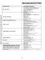
REPAIR AND ADJUSTMENT
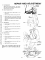
9.
another free manual from www.searstractormanuals.com
10.
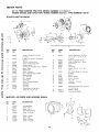
Fueo Replacement
/
Replace with 30 amp automotive
- type, plug-in
fuse. Fuses can be purchased at alt Sears Service
Centers and most retail stores.
!
Check Transexle
Block up rear axle (Fig, 39)
tractor jack.
b.
Remove
Reposition
PLUG
FILLER
rear
wheel
securely
by removing
or use a
hub
FIGURE
bolts.
c. Remove filler plug (Fig. 39) from transaxle.
Oil
level must be even with plug threads. See your Sears
Service Center ff additional oil is required, Replace
filler plug.
d.
TRANSAXLE
Oil Level
a.
left
4_,
wheel.
Secure
with
39
WIRE
CONNECTION
hub bolts.
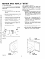
? 1. Hood Removal
a.
12.
Lift
hood.
tion
(Fig.
Disconnect
headlight
b,
Unscrew one screw
(Fig. 40).
c.
Pivot hood and side panel
tractor (Fig. 4 I).
d.
To replace,
Mower
wiring
connec-
40).
reverse
at rear of each side panel
the
forward
above
and lift
FIGURE 40
off
procedure.
Removal
a
Lower
mower.
b
Pull the four (4) release pins out of suspension
brackets (Fig. 42).
c
Pull back on attachment
place.
d,
Slide mower
forward
primary mandrel.
and
e.
Slide mower
under
out from
lift lever and lock into
remove
belt
from
tractor.
ATTACHMENT
HANDLE
NOTE:
IF AN ATTACHMENT
OTHER
THAN
THE
MOWER DECK IS TO BE MOUNTED ON THE TRACTOR,
REMOVE THE L.H. AND R.H. SUSPENSION ARMS (FIG.
42).
SUSPENS!ON
ARM
BELT ....
BRACKETS
'/ ,_/I )
RELEASE
PiN
23
BRACKETS
/
FIOURE
42
REPAIR AND ADJUSTMENT
13,
Level Mower
Housing
Front to Rear Mower
Move attachment
lift lever to full "'UP" position. After
leveling side to side, measure Bottom of Curl at FRONT
AND REAR OF MOWER. The bottom of curl at the R.H.
front flanges should measure 3/4"" lower than at the R.H.
REAR flange (Fig. 44). If adjustment
is required follow
the procedure
below.
Adjust the mower while tractor is parked on level ground
or driveway. Make sure tire pressures are 14 PSI in front;
10 PSI in rear.
Side to Side Mower
a.
Adjustment
Move attachment
a.
rift lever to full "'UP"position
another free manual from www.searstractormanuals.com
(Fig. 46).
b. Use a ruler to make sure bottom
mower deck are the same height
on each side (Fig. 44).
C,
d.
Adjustment
of curl at rear of
from the ground
b.
If adjustment is required, snap out access cover
on L,H. side of tractor above footrest (Fig. 43).
To raise left side of mower, loosen nut "'B'" and
screw nut "'A" down on adjustment
rod.
To raise front of mower loosen nuts "'D". Screw
nuts "'C'" up onto suspension
arms (Fig. 45).
NOTE: SCREW NUTS "'C'" ON BOTH SUSPENSION ARMS THE SAME NUMBER OF TURNS
SO MOWER WILL REMAIN LEVEL. Tighten nuts
"'D'" securely.
To lower front of mower
loosen nuts "'C".
Screw nuts "'D'" down suspension arms. NOTE:
SCREW NUTS "D"
THE SAME NUMBER
OF
TURNS
SO MOWER
WILL REMAIN
LEVEL.
Tighten nuts "'C'" securely.
e. Adjust until both rear mower
flanges are the
same height above the ground.
Tighten nuts
"'A'" and "'B'" securely.
c.
f,
d . Use attachment
lift lever to set mower
proximate
cutting height you need.
Snap access
cover in place.
e.
_AD
//
With mower deck at desired
wheels
(Fig. 46) to lowest
touching
the ground.
at the ap-
Use clevis pin (Fig. 46) to set gauge wheels
lowest point without touching
the ground.
JU'STMEN'I"
NUT
.oo
"A"
©
NUT
"'B'"
BOTTOM
CURL
IFRONT FLANGES)
FIGURE 43
FtGURE
height, set gauge
position
without
44
BOTTOM
OF CURL
{REAR FLANGESI
_'_
24
OF
CURL
BOTTOM
{REAR FLANGES)
at
REPAIR AND ADJUSTMENT
14.
Blade Drive Belt Removal and Replacement
BELT ROUTING
DECAL UNDER MOWER
a.
Remove mower
from
tractor
b.
Remove
top
cover
Iockwashers
and nuts
self
from
0
DECK COVER.
(see page
tapping
idler arm
23).
screws,
bolt.
NUT
c. Roll belt over
another free manual from www.searstractormanuals.com
d. Pull belt
the top of the R.H. mandrel.
off all other mandrels,
e.
Remove any dirt and grass which may have accumulated
around mandrels and idler arm.
f.
Check deck idler arm assembly and flat idler to
see that they rotate freely (Fig. 47).
g.
h.
Be sure
assembly
"'D"
SUSPENSION
ARMS
NUT "D'"
spring is hooked in deck idler arm
and on bolt in mower housing IFig. 4 7).
FIGURE 45
->-
Install new belt in groove
of L.H. mandrel
sheave, lower groove of center mandrel sheave
and around flat idler as shown (Fig. 47).
7i_/
_'_
ATTACHMENT
LIFT LEVER
From a position at discharge end of mower, roll
belt into groove of R.H. mandrel sheave (Fig.
47).
J.
Rotate center mandrel sheave by hand
sure belt is in grooves properly.
MANDREL
SHEAVES.
LADES WILL
ROTATE
I
k. Reassemble
top
screws securely.
I.
Install
mower
15. Attachment
cover
to
to tractor
Lift Spring
WITH
deck.
GAUGE
WHEEL
CENTER
Tighten
(see page
RETAINER
SPRING
to make
;
CLEVIS
all
IDLER
10).
ARM
NUT
Adjustment
L.H. MANDREL
Due to different
weights of attachments,
the attchment
lift spring may require adjustment.
The adjustment
bolt
is located on rear of tractor top left side (Fig. 48).
a . Holding spring bushing
nuts.
b.
Turn
adjustment
spring
and
attachments).
c.
d.
bolt
reduce
with wrench,
clockwise
lift
(for
jam
nut against
spring
CENTRAL
IDLER
MANDREL
SHEAVE
R.H, MANDREL
SHEAVE
SHEAVE
J
to extend
FIGURE 47
heavier
Turn adjustment bolt counterclockwise
(for lighter attachments).
Retighten
.....
FLAT
FIGURE 46
loosen jam
(F-_k)
effort
-
PIN
SPRING
BUSHING
(jF_)
ENT
SPRING
bushing.
NOTE: DO NOT ADJUST FOR MAXIMUM
SPRING TENSION WHEN USING UGHT ATTCHMENTS
SUCH AS A
MOWER. ADJUST LIFT LEVER SPRING TO AiD IN LiFTING ATTCHMENT.
DO NOT OVER POWER SPRING.
WHEN REMOVING ATTACHMENT
ALWAYS
ADJUST
WITH SPRING TENSION TO ITS LOWEST POSITION
JAM NUT
25
FIGURE
48
REPAIR AND ADJUSTMENT
A.
LOCKWASHER---.-_<_
ADE
another free manual from www.searstractormanuals.com
TREATED
HEX HEADBOLT
HEAT--_)
GRADE 5
16.
System
It is important
to prevent
gum deposits
from forming
in essential
fuel system parts such as the carburetor,
fuel filter,
fuel hose,
or tank during
storage.
Also,
experience
indicates
that alcohol blended
fuels (cafled
gasoho/ or using ethanol
or methanol)
can attract moisture which leads to separation
and formation
of acids
during storage. Acidic gas can damage
the fuel system
of an engine while in storage. To avoid engine problems,
the fuel system should be emptied before storage of 30
days or longer.
FLAT WASHER
FIGURE
Fuel
B.
Engine
Oil
Drain (with engine warm) and replace
engine oil, (See chart page 16).
49
C,
Blade Replacement
It is not necessary to remove mower
from tractor for
blade replacement.
Moving adjustment rift lever to up
(Rear) position
will permit access to blades.
a.
Remove the hex head bott, Iockwasher
washer (Fig. 49).
b,
Remove
C.
Clean
d
Instafl new blade with SHARP EDGE DOWN and
secure with flat washer, Iockwasher
and hex
head bolt. TIGHTEN SECURELY.
and discard
top and bottom
and flat
old blade.
of mower
housing.
D.
ALWAYS USE GRADE 5 HEAT TREATED
BOLTS TO ATTACH
BLADES.
CHECK
BOLTS IN BLADES OCCASIONALLY
TO
MAKE SURE BOLTS ARE TIGHT. TORQUE
BOLTS 30 - 35 FT, LBS,
E.
A GRADE 5 HEAT TREATED BOLT
CAN BE IDENTIFIED
BY THREE
LINES ON THE BOLT HEAD AS
SHOWN ON LEFT.
17. Storage
Remove mower from tractor for winter storage. When
mower is to be stored for a period of time, clean it
thoroughly,
cemove all dirt, grease, leaves, etc. Store in
a clean dry area.
26
clean
Cylinders
1.
Remove
2,
Pour one ounce of off through
into cylinders.
3,
1-urnignition key to "'START"
seconds to distribute
oil.
4.
Replace
spark
with
plugs.
new
spark
spark plug holes
position
for a few
plugs.
Battery
1.
Prior to storage,
battery.
2.
After a period of time in storage,
require recharging.
General
Clean engine,
matter.
F.
with
clean
terminals
and
battery
top of
may
Cleaning
battery,
seat,
finish,
Store in a Clean Dry Area
etc.
of all foreign
another free manual from www.searstractormanuals.com
TROUBLESHOOTING
POSSIBLE CAUSE
CAUSE/REMEDY
WILL NOT START
Push Clutch/Brake
Pedal into Brake
Move Attachment
Clutch Switch
to
Fill Tank with Gasoline,
Check Fuel
(clean if necessary)
Replace Fuel
Check fuse for fault and replace
Recharge
or replace Battery
Check Wiring
(SEE INDEX)
Position
"'Disengaged
Position"
Line and Carburetor
Filter
Replace Spark Pluc.ls and adjust _lap
Charge
Battery
Replace Ignition
Switch
Engage
Clutch/Brake
Pedal
Move Attachment
Clutch Switch
to "'Diseng#_ged
Replace
Interlock
Switch
Replace
Solenoid
WILL NOT TURN OVER
Replace Spark Plugs
Replace Fuse
Check All Wire Connections
Replace
ENGINE CLICKS
BUT WON'T
START
Starter
Char_le or Replace Battery
Piece Throttle
Control
in "FAST"
position
and run starter several times to clear out gas
Remove
and clean Fuel Tank and lines. Replace
Remove Air Filter and clean
Replace Spark Plugs and adjust gap
Replace Battery
Check the wiring and Spark Plugs
Drain Fuel Tank and Carburetor,
use fresh
replace
Spark Plugs
Make necessary
adjustments
to Carburetor
HARD TO START
Major
Engine Overhaul
Shift to a lower gp.ar or reduce load
Remove
and clean Tank; replace Fuel
Remove
and clean Air Cleaner
ENGINE
MISSES
OR LACKS
Make
Clean
POWER
necessary
carburetor
Air Screen
Clean
OVERHEATS
Use
end
Filter
for
any loose
wires
and refill
Air Screen
fresh
Check
fuel
Fuse,
Replace
and _
Switch
Headlight
Check for Fuse fault
Replace
Battery
Replace
Regulator
CHARGE
Replace
OPERATOR PRESENCE SYSTEM WILL NOT
DOWN ENGINE WHEN OPERATOR LEAVES
Filter
Add or change
oi!
Clean Engine Cooling
Fins
Remove
and clean Muffler
or replace
Remove
and clean Air Filter
NO LIGHTS
WON'T
fuel
Fuel
adjustments
Repace
Spark Plugs
Add or change
oil
Check Spark Plugs and cheek
Major
Engine overhaul
Drain Gas Tank and Carburetor
ENGINE
Poe#ion'"
SHUT
SEAT
Carburetor
and
Wire
Connections
Bulbs
and replace
Alternator
Engage
Attachment
Clutch
Check All Wire Connections
Check Seat Switch
Check Operator
Presence
Relay
Check PTO Switch
Check proper
installation
of washers
see page 33
NOTE: THIS TRACTOR
IS EQUIPPED
WITH AN OPERATOR
PRESENCE
SENSING
SYSTEM.
ANY
ATTEMPT
BY THE
OPERATOR
TO LEAVE THE SEAT WITH THE ENGINE RUN
NING AND THE ATTACHMENT
CLUTCH ENGAGED WILL SHUT
DOWN THE ENGINE.
27
under
seat
springs
-
another free manual from www.searstractormanuals.com
TROUBLESHOOTING
UNSATISFACTORY
MOWER PERFORMANCE
UNEVEN DISTRIBUTION
OF CLIPPINGS
Check air pressure in tires
Check front to rear and side to side mower adjustment
Use a slower ground speed
Replace mower blades
Reinstall mower blades with top of blades up
Re-adjust mower drive belt
Clean underside of mower deck
Sharpen blades
MOWER
Install new Mower Drive Belt
Reinstall Mower Drive Belt
Replace Attachment
Clutch Switch
Replace Frozen Mandrel
Replace Frozen Pulley
BLADES WILL NOT ROTATE
EXCESSIVE
MOWER
Replace
Replace
VIBRATION
Bent or Unbalanced
Mandrel, Straighten
Blade
Deck or replace
Let grass dry out
WIND ROWING STRIPPING
OF GRASS CUPPINGS
OR DROPPING
Clean undersideof Mower Deck
Level Mower
Replace
Blades
Level Mower
UNEVEN CUT OR SCALPING
Adjust Gauge Wheels
Replace
SERWCE
SERVICE
Fill in dates
as you
Blades
RECORD
RECORD
complete
regular
SCHEDULE
service
FIRST
2
HOURS
EVERY
5
HOURS
EVERY
25
HOURS
Blades
X
Brake Adjustment
X
Check
Engine
Check
Clean
X
Battery
Change
Engine
X
OilOil Level
Air Cleaner
Check
EVERY EVERY
50
100
HOURS HOURS
X
X
X
Element
IVluff[er
X
Clean Air Screen
X
Clean Front
Grill
X
Tractor
X
Lubricate
Replace
Spark
Replace
Air Cleaner
X
Plugs
Element
X
Tires
X
Sears,
Roebuck
and
Co.
reserves
the right
changes
in design
or improvements
without
any
obligation
to install
the
same
upon
heretofore
manufactured,
28
to make
any
imposing
its
terms
REPAIR
PARTS
GT 18 TWIN GARDEN TRACTOR- -MODEL NUMBER 917,255917
SCHEMATIC
12V
RED
POWER
TAKE.OFF
SWITCH
another free manual from www.searstractormanuals.com
RED
CLUTCH
I
OF_
D
_
SOLENOID
RED
2 TURNS
CLOCKWISE(F_)
FROM FUSE
ELECTRIC
CLUTCH
RED
AMMETER
_
[852030A
M
BLACK
F USE
BLACK
IGNITION
SWITCH
RED_
'_
SEAT
-Oa
{NOT
30 AMP
SWITCH
B,,CK
i
I
I
I
OCCUPIED_
BLACK
BLACK
J
L ......
..a
}GNITION
UNIT
SPARK
PLUGS
8
RED
BLACK
5 AMPS DC (POS.
22 VAC {MIN.)-__
DIODE
5 AMPS DC INEG )__ASSEMBLY_'I_
NOTE: WITH ENGINE "_
_
1
I
RUNNING
BATTERY
I
LIGHTS
@ 3600
IN-LINE
RPM,_'_
OFF
*UqDUCIIVE
ED AS SEEN
DASHBOARD.
TYPE
WIRE
COIL-
FROr(i'£A-CK-OF
P_ i
I
I
I .......
I RED
ENGINE COIL
_L_._j
....
(ALTERNATOR)
v
I ORANGE
LIGHT
SWITCH
BLUE
owN
/"
CHASSIS
GROUND
IGNITION
SWITCH
POSITION
CIRCUIT
OFF
M-G
ON
B-L
START
B-S
PTO SWITCH
POSITION
i.
WIRING INSULATED
CLIPS
NOTE:IF
WIRING
INSULATED
CLIPS WERE REMOVED FOR SERVICING OF UNIT,THEY
SHOULD
BE REPLACED
TO
PROPERLY
SECURE YOUR WIRING
29
CIRCUIT
MAKE
OFF
B&E. C&O
ON
B&A
D
C
B
E
A
another free manual from www.searstractormanuals.com
r_
T_w
o_
Tm_
iJl
cn
Lu
O
m
!
r_
0
LU
\
Z
_
_w
co
im
a_
ml
cE_
_mm
_u
t_
€_
!
_€
Im
Ull
30
REPAIR
PARTS
GT 18 TWIN GARDEN TRACTOR- -MODEL NUMBER 917.255917
another free manual from www.searstractormanuals.com
ELECTRICAL
KEY
NO.
PART
NO.
1
2
3
4
!09310X
STD365402
109787X
109788X
5
6
7
8
9
!0
!1
12
!3
14
417! R
108240X
9!38R
7603J
100541K
109596X
I09081X
10090400
STD541225
17190408
!5
!6
!7
18
19
20
21
22
23
24
104445X
71031008
73951000
106315X
121041X
4152J
108824X
74610628
STD523707
I21080X
DESCRIPTION
Key
Switch
Bezel
Nut _
Clip
Switch
Battery
Tray
Tube
Clamp
KEY
NO.
PART
NO.
DESCRIPTION
25
2 6
2 7
2 8
29
30
3 1
32
33
3 4
11050600
4021J
4022J
4799J
7!9J
74641008
5115J
109550X
106367X
108170X
35
36
3 7
38
39
40
19132203
STD55!
137
72240460
11030400
STD541625
102476X
4 1
42
STD522507
STD551025
Diode
Assembly
Harness - Ignition
Bulb - Headlight
Fuse _ 30 Amp
Bolt - Hex 3/8
24 x t - 3/4
4 3
4 4
4 5
46
48
STD54 !025
STD551125
110859X
12!064X
109748X
*Bolt _ Hex 3/8
Cable _ Ground
49
50
120353X
121111X
!01539X
110917X
Ignition
- Ignition
Ignition
Light
Battery
Drain
- Hose
Solenoid
Washer
Lock 1/4
*Nut - Hex Jam I/4 - 20
Screw
- Hex Washer Thread
1/4
20 x 1/2
Switch
Interlock
Screw
- Hex Washer No.
Nut - Keps No. !0 - 32
Cutting
10 - 32 x 1/2
16 x 3/4
Washer - Lock - Ext.
Switch
- P, T. O.
Nut - Hex
Cable
Cover
B
13
C
14
O
16
'"
I/2
Spacer - Clutch
Stop - Clutch
Washer
* Washer - Lock 3/8
Bolt - Carriage
1/4 - 20 x 7 - I/2
Washer - Lock - Int./Ext.
Tooth I/4
*NutWing 1/4-20
GuardTerminal
*Bolt - Hex 1/4 - 20 x 3/4
* Washer 9/32 x 5/8 x 16 Go.
*NutHex 1/4 - 20
" Washer - Lock
Harness - Light
Switch
- Seat
1/4
Socket
Relay - Operator
Cap Set - Battery
Ammeter
Sheet
Manual
Presence
Instruction,
- Owners
HARDWARE--PURCHASE
F
25
3/8
- Battery
- Terminal
Screw
1032x
Cable - Starter
Clutch - Electric
*STANDARD
A
Tooth
(-_
30
Tractor
15 ° Slope
LOCALLY
REPAIR PARTS
GT 18 TWIN GARDEN TRACTOR- -MODEL NUMBER 917.255917
CHASSIS
AND
ENCLOSURES
42
77,
M
another free manual from www.searstractormanuals.com
6
65
10\
"39
_/52
11
48
_
64
44
26
37
G
c
c
79
REPAIR PARTS
GT 18 TWIN GARDEN TRACTOR- -MODEL NUMBER 917.255917
CHASSIS
KEY
NO.
1
2
another free manual from www.searstractormanuals.com
3
AND ENCLOSURES
PART
NO.
DESCRIPTION
120066X
121069X
Seat
Pan.
105529X
Bolt
5
6
7
8
9
10
11
12
13
14
15
73680500
2751R
109641X
105513X
73680600
109593X
106202X
105801X
STD523707
105567X
17490608
16
17490616
Seat
- Shoulder
Nut- Lock 5/16 - 18
Clip
Grommet
Bracket
- Pivot, Seat
Nut- Lock 3/8 - 16
Fender
Reflector
- Taillight
Decal
*BoltHex 3/8 - 16 x 3/4
DecalChassis
Screw - Hex Washer Thread
3/816 x 1/2
Screw-HexWasherThreadRoliing
17
18
19
21
22
23
1055!1X
121068X
121067X
105531X
105509X
106020X
3/816x 1
Strap-Fender
Spring - Compression,
Spring - Compression,
Nut - Push
BracketFender
Tank - Fuel
24
25
26
27
28
29
30
31
32
33
34
35
36
109462X
106082X
6999R
7834R
7833R
I05465X
105466X
105464X
1 I0892X
110893X
7982J
74760716
73680700
Cap- Fuel
Pad- Spacer
Clamp - Hose
Line-Fuel
Line - Fuel
Footrest
- L.H.
Pad- Footrest
FootrestR.H.
Rail- Frame - R.H.
RaiI-FrameLH.
Drawbar
Bolt- Hex 7/1614 x 1
Nut- Lock 7/1614
37
38
39
40
41
42
108403X
105562X
1084 IOX
121054X
121055X
106013X
Panel- Side, R.H.
Decal
Panel - Side, LH.
Bracket-Pivot,
Frame,
BracketPivot, Frame,
Hood
43
44
110875X
105528X
Shield
Grill
45
!08512X
Bracket-
A
_ 3
_5
B
_
C
9
_13
_9
- Heat,
Pivot,
D
_
Rolling
L H.
R.H.
DESCRIPTION
46
47
108513X
1060,03X
BracketPivot,
Lens R.H.
48
106004X
Lens
49
51
52
53
54
55
56
57
58
59
60
61
62
110897X
108067X
106091X
106090X
110350X
109139X
106868X
4900J
3645J
8710J
105806X
105568X
19131416
Bezel
Nut- Pal
HingeRoll.
Hinge - L.H.
Strap - Grill
Decal - Fender
Deca! - Drive Belt Schemahc
DecalClutch/Brake
Bushing
Stern - Fuel Tank
DecalGrill
63
106092X
Support
64
65
66
67
70
106088X
106813X
106814X
!06974X
106909X
71
72
73
74
75
77
78
79
80
81
82
83
84
106910X
108402X
121093X
19131614
120609X
108743X
108744X
I05500X
121094X
19151616
74330808
10040800
19171912
L.H.
L.H.
Decal - Grill (S tripe)
Washer 13/32x
7/8x
- Heat
16 Ga.
Shield
Strip - Foam
DecalStripe,
Side
DecalStripe, Side
DecalCaution
Panel,
Panel,
LH.
R.H.
Screw - Special
Washer
U-Clip
Cap, Spring
Washer, 13/32 x 1 x 14 Ga.
**Washer
7/16 x 2 x 12 Ga.
Decal Stripe, Hood,
L.H.
Decal Stripe,
Hood, R, H.
Retainer,
Belt, Lower
Shoulder
Bolt, 5/16 - 18 UNC
Washer, 5/16x
1 x 16 Ga.
Screw. Hex 1/2 - 13 x3/4
Gr. 5
Lockwasher,
1/2
Washer, !7/32x
1 3/16x12
WA RE-
PURCHA
Ga.
SE LOCA LLY
THAT THE CORRECT WASHERS
BE INSTALLED
UNDER THE SEAT SPRINGS.
KEY
# 75 IS INSTALLED
UNDER THE LEFT SPRING
ONLY, KEY#74
IS INSTALLED
UNDER BOTH LEFT
AND RIGHT
SPRINGS.
THE OPERATOR
PRESENCE SYSTEM
(page 13) WILL NOT OPERATE
WITHOUT THESE WASHERS.
R.H.
F
_
Grill,
** IT IS IMPORTANT
R.H.
L.H.
E
"15 _16
PART
NO.
*STA NDA RD HARD
Front
Grill,
KEY
NO.
G
9
135
_)36
H
_
_
J
70
71
_72
_
L
51
_16_
M
p
)13
_-_ 62
Q
_80
_
_82
81
83
84
33
REPAIR
PARTS
GT 18 TWIN GARDEN
GROUND
TRACTOR-
-MODEL
NUMBER
917.255917
A
DRIVE
/8
iW
49
another free manual from www.searstractormanuals.com
G
H
66
/
/.43
32
90
94
98
./
/
//
96
93
REPAIR
PARTS
GT 18 TWIN GARDEN TRACTOR- -MODEL NUMBER 917.255917
GROUND
another free manual from www.searstractormanuals.com
KEY
NO.
DRIVE
PART
NO,
DESCRIPTION
2
110864X
4
6
8
9
120374
110890X
170887X
8545J
Engine
Model Number
Type 1209 Trim 0!
Valve, Oil Drain
Tube- Fxhaust
Muffler
Gasket. Muftler
X
PART
NO.
DESCRIPTION
67
68
6,0
70
71
STD571812
!06021X
120055X
; 7720408
110879X
72
73
74
75
;1050600
$7D541137
8883R
677A637
76
74370612
77
78
79
80
81
82
83
84
85
86
87
88
89
74760614
7920J
72740405
STD541025
7229J
1685H
STD533110
5308J
7241J
73530600
100604K
5102J
71673
*Pin, Roll, 3/16x
1 - 1/4
Spring,
Extension
Control,
Throttle
Screw, He_, Thd. Cut. 1/4-20x
Control, Choke
Washer rock.
Ext Tooth. 3/8
"Nut, 3/8-24
Cover, Pedal
Bracket,
Brake
Screw, Mach.,
Unct. FL Hd.,
3/816x3/4
Bolt, Hex, 3/8 - 16 x 7/8
Band, Brake
Bolt, Carr., 1/4
20x5/8
*Nut, Hex, I/4 - 20
Guide, Rod, Brake
Nut, Lock, 5/16 - !8
*Bolt, Cart., 5/16 - 18 x 3/4
Rod, Brake
Spring,
Compression
Nut, Lock, 3/8 - 24
Yoke
90
91
92
93
94
95
96
97
98
99
1 O0
109767X
110042X
634A 692
7563R
12000034
1304H
106277X
105588X
7154J
65139
59192
KEY
NO.
422437
10
11
12
13
74570412
STD551125
1 I0867X
STD523707
14
STD523112
15
16
17.
18
19
20
22
23
24
2,5
26
27
28
STD551131
STD54103
73680600
_
STD551137
19131674
72110608
121063X
19131612
_
121065"x
120157X
106023X
29
30
31
32
33
34
35
36
72110616
STD533707
102403X
STD551037
101347L
STD533710
STD541037
105592X
37
38
207J
12000039
Bolt, Cart., 3/816x2
*Bolt, Car_, 3/8 - 16 x 3/4
Idler, Flat
*Washer,
!3/32 x 13/16 x 16 Ga.
Bracket,
Flat Idler
"Bolt, Cart.. 3/816 x 1
*Nut, Hex, 3/8 _ 16
Bracket,
Clutch w/Bearing(Inc.
Key
No. !06)
Washer, Hardened
Klip Ring
39
40
41
42
43
44
110484X
STD523715
73930600
101355X
STD570907
101356L
Idler, Grooved
=Bolt, Hex, 3/816x 1 - 1/2
Nut, Lock, 3/816
Sprino.
Extension
*Pin, Cotter 3/32 x 3/4
Rod, Clutch
101
102
103
!04
; 05
106
214J
$7D541410
633A109
2228M
74760724
101350K
45
46
47
104360X
STD523720
19131413
Idler, Flat
*Bolt, Hex, 3/816 x2
Washer, !3/32x7/8x13Ga,
108
109
110
9858M1
5304J
74321016
48
49
50
51
105597X
104577X
STD523710
1.7190512
Retainer,
Belt
Adapter
*Bolt, Hex, 3/8 - 16 x 1 Gr. 5
Screw. Hex, Slotted,
5/1618x3/4
Rod, Sh_ft, Hi-Lo
Bracket,
Rod, Shill
Knob
Nut. Lock, 5/!6 - 18
111
! 12
113
114
715
116
117
118
119
120
2751R
104601X
STD522507
73680400
19131210
73680700
11050500
76020816
101358K
19131512
121
122
124
125
126
127
STD551025
72140506
74760624
74760620
110895X
120615X
54
122253X
55
56
57
58
59
105598X
100196K
73680500
122268X
110883X
60
61
62
63
64
65
66
!20404X
74760716
STD551143
120332X
9204H
104375X
19252016
*STANDARD
S¢,rew. SocketHd.,
1/4-20x3/4
*Washer,Lock,
!/4
Base, Engine
*Bolt, Hex, 3/816 x 3/4
Bolt
1
5/16-18x
1-1/4
Washer
Lock5/16
Nut 5/1618
Nut, Lock, 3/816
Pufley, Ground Drive,
*Washer, Lock, 3/8
Washer, 13/32 x 1 x 14 Ga.
Bolt, Carnage3/816x 1
Bracket,
V-Pulley,
Drive, Mule
Washer, 13/32 x 1 x 12 Ga.
Pulley
_
5 L_ _ L
Bracket, Idler, Flat
Guard, Belt, Mule Drive, Flat Idler
Guard, Belt, Mule Drive, V-Idler
Connecting Link, Spring K!ip
V-Belt
Bracket,
Support,
Transaxle
Bolt. Hex, 7/1614 x I
*Washer, Lock 7116
Pulley, 7ransaxie
Nut, Lock, 1/2 - 20
Shaft, Foot Pedal
Washer, 25/32 x 1 - 1/4 x 16 Ga.
HARDWARE-PURCHASE
LOCALLY
35
Pin, Clevis
Cap. Plunger
Rod, Parking
Brake
Decal, Engine
Bushing
and Wheel Hub
Washer, Thrust, Axle
Klnp Ring
Bolt, Hub
Wheel, Rear
Tire, Rear
Tube, Tire (Not furnished)
Valve, Tire
Cap. Valve
Drum. Brake
*NutLock No. 10-24
Gear Shift Lever Assembly
Key, Woodruff
Bolt, Hex 7/16Bearing
- Idler
14 x 1 - 1/2
Key- Woodruff
ActuatorSwitch,
Interlock
ScrewFin 10-24x
1
Clip
Bracket
- Interlock
*BoltHex 1/4- 20x3/4
Nut- Crownlock
1/4 - 20
Washer 13/32x
3/4 x I0 Ga.
Nut - Crownlock
7/16 - 14
WasherLock Ext. Tooth 5/16
Pin Cotter
1/4 x 1
BracketAssembly
Clutch
Washer 13/32x
1 x 12 Ga.
* Washer 9/32 x 5/8 x 16 Ga.
BoltCarriage
5/16 - 18 x3/4
Bolt - 3/8 - 16 x .1 - 1/2
Bolt-Hex,
3/816x 1 - 1/4
Nyliner
Spark Arrester
Kit
1/2
REPAIR
PARTS
GT 18 TWIN GARDEN
TRACTOR-
-MODEL
NUMBER
917.255917
STEERING
O----50
/_
.82
another free manual from www.searstractormanuals.com
51 22 ._.__ _39
/38
(,
_ _'8_J
84
10 44
17
14
.18
21
4
71
2/
36
/
REPAIR PARTS
GT 18 TWIN GARDEN TRACTOR- -MODEL NUMBER 917.255917
STEERING
KEY
NO.
PART
NO.
DESCRIPTION
106230X
8134H
another free manual from www.searstractormanuals.com
106228X
4
5
6
7
8
9
10
11
12
13
14
15
16
17
18
19
20
21
22
23
24
25
26
27
28
29
3O
31
32
33
34
278H
9040H
106045X
6266H
12000029
5284J
STD523707
73680600
674A244
1309H
5298J
74781044
STD551162
STD541052
6855M
106046X
120424X
110497X
STD551137
STD541137
5292J
108137X
19292016
109849X
STD523720
35
36
37
38
39
4O
41
42
43
44
45
102458X
12000034
700713N
100711L
19133808
106014X
6266H
1055!9X
108408X
105525X
19171416
A
B
73510600
102439X
104239X
72110608
101274N
17490612
Tire, 16x 6.50
Tube, Front (not furnished
tractor)
Front Wheel (inc. Key No.
of Key No. 4)
Fitting,
Grease
Bearing
Spindle,
R.H.
Bearing,
Thrust
Klip Ring
Bracket,
Axle
*BoltHex 3/8!6 x 3/4
Nut, Lock, 3/816
Axle. Front (Inc. Key 13)
Bearing
Tube, Pivot, Axle
Bolt, Hex 5/8-11
x 2 3/4
*Washer.
Lock 5/8
*Nut, Hex 5/8 . 11
Fitting, Grease
Spindle,
L.H.
Sector Assembly
KEY
NO.
with
3 and
Gr. 5
DESCRIPTION
46
4 7
4 8
4 9
72110622
106486X
106042X
17240408
5 0
5 1
5 2
105810X
100710L
STD525020
73680800
19172610
120542X
677A451
7190J
STD523720
19131413
STD541037
52!3J
73680500
7985J
65139
59192
108811X
108456X
5 3
5 4
5 5
56
57
5 8
5 9
60
6 1
62
63
64
6 5
6 6
Link, Drag
"Washer,
Lock 3/8
"Nut, Hex 3/8 - 24
Bushing,
Beflcrank
Bellcrank
Washer 29/32x
1 - 1/4 x 16 Ga.
Rod; Tie
*Bolt, Hex 3/8 - 16 x 2 Gr. 5
Nut, Keps 3/816
Bracket,
Support,
Steering
Bearing, Flanged
Bolt, Carr. 3/816 x 1 Gr. 5
Support,
Steering
Screw,
Hex Washer
T,hd, Rolling
3/816x3/4
6 7
68
6 9
7 0
7 1
72
73
74
75
7 6
7 7
78
79
80
81
Shaft, Steering
Klip Ring
Wheel, Steering
Adapter,
Steering
Washer
82
8 3
84
85
86
Sleeve, Steering
Bearing
Dash, Lower
Dash
87
88
89
Bracket,
Washer
C
PART
NO.
Bolt-
G
H
Gate,
3/8
- 16x
Shift
Screw,
Hex Washer
1/4-20x
1/2
Decal, Insert
Thd.
Cap, Steering
Wheel
*BoltHex 1/2 - 13x 2
Nut, Lock lJ2 - 13
Washer
17/32 x 1 - 5/8
Bracket, Idler
L 32
_
_11
_11
Support,
Battery
Stem, Valve
Cap, Valve
Decal, Dash, Instruction
Decal, Instruction
8022J
Dash
K
*Bolt - Carriage
5
Washer
13 32 x
Washer 25 32 x
Bolt, Hex 5,76Cap - Hub, Front
1678x 34
1 - 1 4 x 7 Ga,
1 - 58,x
16 Ga.
18x
1
Bushing
- Handle
Washer
11 32 x 78x
16 Ga.
*Bolt, Hex 3/8 - 16 x I Gr. 5
Clip - 3'8
Decal - Adjustment
Tube
Collar Weld Assy
Spindle Stop
Clamp, Hose
Plug
HARDWARE--PURCHASE
L
M
N
i46
345
_78
L;
LOCALLY
®,, ?,,9
'L_
(_
@
59
22
_22
_75
_'_62
22
60
@45
[_ 47
@ 22
6o
37
x 10 Ga.
Pin, Mounting,
Idler Bracket
Nyliner
Joint - Tie Rod - R,H. Thread
Joint - Tie Rod - L.H, Thread
RodTie
Nut - Hex Jam 3 8 - 24 L.H.
*Nut - Hex Jam 3 8 - 24
J
_60_59
_32@ 22
68
Cutting
Pulley, Idler
Spring
"Bolt, Hex 38 - 16x2
Washer
13 32 x 7 8 x 13 Ga.
"Nut - Hex 3/8 - 16
Bracket,. Frame Front
Nut, Lock 5 16 - 78
82
_10
2-3/4
106615X
120200X
109850X
I09851X
7919J
73700600
STD54!337
STD533707
19132007
19252616
74930516
104757X
100644K
19117416
STD523710
100207K
108367X
120!99X
120195X
110946X
120800X
*STANDARD
Support,
Dash
!7/32 x 7/8 x 16 Ga.
D
E
F
Carr.
Spacer
Cover,
@22
_q8O
_60
_
81
_
62
another free manual from www.searstractormanuals.com
l
\\
° \
\
\
38
\
/
/
REPAIR
PARTS
GT 18 TWIN GARDEN TRACTOR- -MODEL NUMBER 917.255917
another free manual from www.searstractormanuals.com
MOWER LiFT
(4
KEY
NO.
PART
NO.
!
2
3
4
5
6
7
8
9
10
!1
12
13
14
15
16
17
18
100734K
11OS07X
110811X
STD570907
2876H
19131016
105505X
110871X
STD523107
73680500
19
20
21
STD561108
105041X
STD511005
22
23
24
25
26
27
28
29
30
31
32
33
73631000
120137X
DESCRIPTION
Handle,
Nut
12035DX
STD522505
73680400
106351X
110436X
105036X
105040X
74750806
110 1ox
19151216
12000037
7594J
7901J
73900400
7596J
105503X
4939M
74,760616
KEY
NO.
Adjust,
DESCRIPTION
Lever
Lift
34
3 5
!21002X
12'1006X
Rod, Adjust,
Lift
*Pin, Cotter,
3/32 x 3/4
Spring
Washer 13/32 x 5/8 x 16 Ga.
Cover, Access
Shield, Heat, Rear
*Bolt, Hex, 5/16 - 18 x 3/4
Nut, Lock, 5/16 - 18
Brace, Heat Shield
*Bolt, Hex, t/4 - 20 x 1/2 Gr. 5
Nut, Lock, 1/4 - 20
36
37
38
39
105723X
STD523710
109413X
74780616
40
STD55_050
*Washer
Ga.
4 1
4 2
43
44
9135R
!05429X
105413X
STD55!
150
Plug
Grommet,
Split
Foam - Strip 6"
Bracket,
Fuel Pump
Screw,
Sl. Hex Hd. No. 8 - 32 x
3/8
*Washer,
Lock No. 8
4 5
46
4 7
4 8
49
50
5 1
STD541050
105501X
STD533707
73680600
674A247
105589X
STD533110
Retainer
Spring
Arm, Suspension
Stud, Pivot Center
"Washer,
Lock, 1/2
*Nut, Hex, 1/213
Bracket, Suspension,
Mower
*Bolt, Carriage,
3/8 - 16 x 3/4
Nut, Lock, 3/8 - 16
Pump,
*Screw,
1/2
52
53
64
19111610
121045X.
121046X
5 5
17490608
56
57
73800600
STD54!037
Klip Ring
Bracket,
Lift, L.H.
Bolt, Shoulder
Nut, Hex Flange 1/4 - 20
Link, Lift, L.H.
Link, Lift, R.H.
58
59
60
5328J
STD551037
5329J
62
63
73930600
106086X
Retainer,
Spring
Washer, Lock3/8
64
55
12000022
!9 292016
Fuel
Hex Hd.
Lift
PART
NO.
No.
10-
24
x
Nut, Lock No. 10 - 24
Shaft,
Lift
Trunnion,
Stop Depth
Washer
15/32 x 3/4 x 16 Ga.
*STANDARD
HARDWARE--PURCHASE
B
C
D
E
Q 13 © lo
19
F
_
@220z9
G
28
_)47
H
_51
©6z
16x
1
I
1 - 1/16x
13
Spring - Ass'y.
- Assist,
Lift
Guard, Belt, Engine
*Bolt, Carriage,
5/1818 x 1
Washer
11/32 x 1 x 10 Ga.
Panel, Pnt. Side, R.H.
Panel, Pntr 5ide,'L
H.
Bolt,
3/8-
Hex Washer
16x
1/2
Thd. Rolhng
Nut, Lock, 3/8 - 16
*Nut, Hex 3/8 - 16
BoltAdjust, Spring, Assist
*Washer
13/32 x 13/16 x 16 Ga.
Bracket,
Spring
. Assist
Nut - Centerlock 3/8 - 16
Strip - Foam
Klip Ring
Washer 29/32 x 1 - 1/4 x !6 Ga.
J
K
55
_j
37
48
_1o
16x
17/32x
LOCALLY
(_21
(_
Rod, Detent
Plunger, Lever
*Bolt - Hex 3/8Grip, Handle
Bolt, Hex, 3/8-
REPAIR PARTS
GT 18 TWIN GARDEN TRACTOR- =MODEL NUMBER 917.255917
MOWER
51
another free manual from www.searstractormanuals.com
\
52
41
12
/
38
35
53
35
/
4O
47\
69_
35
38
55
35
\
73
34
71
40
9
\
45
4O
REPAIR PARTS
GT 18 TWIN GARDEN TRACTOR- -MODEL NUMBER 917.255917
MOWER
KEY
NO.
another free manual from www.searstractormanuals.com
1
2
3
PART
NO.
I05415X
106022X
17490508
4
5
6
7
8
9
10
1 t
12
13
14
7631J
72110505
STD551137
STD54 1031
8418J
72140506
!685H
STD557031
106037X
106038X
17490612
15
16
1 7
18
19
2O
2 1
22
23
24
25
2 6
2 7
28
29
30
3 I
106635X
STD623715
STD551137
19732012
674A213
7834J
7835J
72110522
19111610
102403X
STD5237!5
STD541037
104361X
STD523712
19117216
8438J
106224X
32
33
34
3 5
105448X
105449X
STD533707
73680600
KEY
NO.
PART
NO.
DESCRIPTION
3 6
3 7
38
39
I05453X
5565J
4939M
4898H
Bar, Ca. Wheel
Pin, Clevis
Runner, L.H.
Bolt, Cart. 5/16 - 18 x 5/8
"Washer - Lock, 5/16
*Nut
Hex 5/76
18
Runner, R H.
Bolt, Carr. 5/1618x 3/4
Nut, Lock 5/16!8
"Washer
11/32x
!t/76x
76 Ca.
4 0
4 1
4 2
43
4 4
45
46
47
105455X
105433X
110237X
705434X
105436X
105441X
78850
3146R
Wheel, Gauge
Brkt., Suspension
Spacer
Brace, Suspension
Parallel Link
Mandrel
Secondary
Mandrel
Primary
Screw
- Hex Washer Thd. Roll
3/8
16 x 3/4
Blade
"Bolt
Hex, 3,/8-24 x 1 1/2 Gr.5
"Washer
Lock, 3/8
Washer
13/32 x 1
!/4 x 12 Ca.
Arm Assembly,
idler
Liner, Bearing
Bea ring
Bolt, Carriage 5/16
18 x 2
3/4
Washer I 1/32 x 1 x 10 Ca.
Pulley, Idler
"Bolt
Hex 3/8
16x
1
1/2
*Nut
Hex 3/8
16
48
4 9
5 0
5 1
5 2
53
54
55
5 6
5 7
5 8
59
50
6 1
62
63
!06381X
STD541050
74 760622
!05435X
3720R
12000039
19171612
105440X
!05458X
105460X
105461X
105459X
73680500
120135X
!9711016
!09785X
Spring
*Bolt
Hex 5/16 18 x I t/4 Gr
Washer 11/32 x 3/4 x 16 Ga
6 4
65
66
706734X
109743X
I06735X
6 8
6 9
70
110452X
3713J
- - -
7 1
73580800
73
74
7 5
76
19171512
72240608
706679X
110884X
DESCRIPTION
Housing, Mower
Cover - Drive, Deck
Screw
Hex Washer
5/1618 x 1/2
Spacer
Decal . V-Belt,
Mower
Bracket,
Bracket,
*Bolt,
Nut,
Ga
Ca.
Thd. Roll
5
Dr., Schematic,
Wheel,
Wheel,
R.H.
L.H.
Carriage 3/8
!6 x 3/4
Crownloek
3/8
76
Retainer,
Spring
Bolt, Shoutder
Brkt., Suspension
DecalWarning
Retainer
- Spring
V-Belt
*Not,
1/2- 13
Bolt, Hex 3/8 - 16 x 1 - 3/8
Pit], Release
Spring
Ring, Klip
Washer
17/32
Decal - Safety Standard
- Not Serviced
Nut
Hex 1/2 . 13
Washer
17/32 x t5/16
Bolt, Carriage 3/8
DecalWarning
V Belt
*STANDARD
B
A
C
D
E
F
G
14
_
HARDWARE-PURCHASE
H
74
135
35
41
x 1 x !2
Ca.
Pin, Clevis
Brkt., Outer, R.H.
Brkt., Inner, R.H
Brtk., Inner, L.H.
BrkL, Outer, L.H.
Locknut
5/16
18
Spacer
Washer
77/32 x 5/8 x 16 Ca.
Shield, Deflector
Spring, Deflector
Bracket, Deflector
Rod, Hinge
Push Not
Instruction
_ Caution Decal
x
12 Ga.
16 x 1
LOCALLY
REPAIR
PARTS
GT 18 TWIN GARDEN TRACTOR- -MODEL NUMBER 917.255917
TRANSAXLE
4
5
6
J
2
another free manual from www.searstractormanuals.com
J
5
20
19
r
7
57
°
73
25
929]
24
42
REPAIR
PARTS
GT 18 TWIN GARDEN TRACTOR- -MODEL NUMBER 917,255917
TRANSAXLE
another free manual from www.searstractormanuals.com
KEY
NO.
1
2
3
4
5
6
7
8
g
10
11
12
13
14
15
16
17
18
19
2O
21
22
23
24
25
26
27
28
29
3O
31
PART
NO.
DESCRIPTIO*J
KEY
NO
PART
NO.
DESCRIPTION
4197R
5845R
4199R
4216R
42!BR
42!7R
6256H
74020652
Axle Shaft
Retaining Ring
Final Drive Gear
Differential
Gear
Differential
Pinion
Differential
Carrier
Axle Thrust Washer
Hex Bolt 3/8 - 24 x 3 - 1/4
(1 '1 Thread Length)
Steel Ball
49
50
51
52
53
54
55
56
57
58
4895H
4222R
1529R
8119M
4220R
4209R
4213R
4442"R
4195R
4214R
Needle Bearing
Needle Bearing
Needle Bearing
Needle Bearing
Thrust Bearing Race
3rd Reduction Pinion
4th Reduction Gear
Spring Shift Fork Detent
Shift Fork, High - Low Range
Thrust Bearing
4th Reduction Pinion
3rd Reduction Gear Shaft
Snap Ring - Crescent Type
High - Low Range Gears
Needle Bearing
Sintered Iron Bearing
Shift Fork Shaft. High - Low Range
Differential
Pinion Spacer
Differential
Pinion Bushing
Gripco C_nterlock
Nut 3/8- 24
Shift Fork- L.H.
Oil Seal
Sintered Iron Bearing
Shift Fork Shaft
Shift Fork- R.H.
Shift Shaft, High - Low Range
Oil Seal
Pressure Relief Valve
Gearcase, Reverse Idler Shaft and
Bearings - R.H. (Inc. Key No's. 17,
18, 25, 33, 50, 63, 76, 77 and 82)
Dowel Pin
Needle Bearing
Thrust Bearing
4th Reduction Gear Shaft
4th Reduction Gear Spacer
Thrust Bearing Race
Gearcase Gasket
59
60
61
62
63
64
4194R
7528R
4208R
4207R
739BH
4203R
6,5,
66
67
68
69
70
71
4204R
2898J
4926H
4205R
4206R
1370H
633A69
72
73
74
75
76
77
78
79
80
81
82
83
84
85
86
87
208J
4201R
12000002
1153R
7392H
3990H
STD541031
Gearcase and Bearings - LH.
(Inc. Key No's. 18, 25, 49, 50 (2),
,51 and 52)
Pipe Plug 1/2 - 14 N.PT.
Oil Seal
Pipe Plug 1/4 - 18 N.PT.
88
89
90
91
92
93
7392M
6272H
4985R
6266H
4212R
4196R
6276H
633A63
8118M
874QH1
122238X
4218R
6252H1
781 OH
4986R
7393R
992 R1
6216H
6262H
122254X
6269H
5855H
105406X
32
33
34
35
36
37
38
39
6277 H
4225R
7396H
4198R
4200R
7395H
6275H
40
45
46
13060400
627 ] H
13020200
47
STD523115
48
10140500
105402X
*HexBolt
5/16- 18x 1 .1/2
Grade 5
Lockwasher 5/16 Extra Heavy
94
95
96
97
g8
43
- Low
3rd Reduction Pinion Spacer
2nd Reduction Gear Shaft
Final Drive Pinion
1st Reduction Gear Shaft
1st Reduction Shaft Spacer
3rd Reduction Pinion - High
2nd Reduction Gear
Needle Bearing
Low Speed Gear and 2nd Reduction
Pinion Cluster
Reverse Gear
Key Hi Pro l/8 x 17/32
Snap Ring - Crescent Type
Intermediate
Speed Gear
High Speed Gear
Thrust Washer
Intermediate
and High Speed Cluster
Pinions
Input Shaft
Low Speed Pinion
ERIng
Reverse Idler Gear
Reverse Idler Thrust Washer
Needle Bearing
"Hex Nut 5/16- 18
1167R
73360700
6270H
7384H
100196K
5384J
2978J
633A85
Sealing Washer
Hex Jam Nut 7/16 - 20
Oil Seal
Reverse Idler Shaft
Control Knob
Gear Shift Lever Bent
Gear Shift Cap
Gear Shift Ball Cover and Pin
8739H 1
4924H
19151516
8105R
Shift Lever Guide Ball - Keyed
Spring
Washer 15/32 × 15/16x
16Ga.
Shift Mechanism Seal
19181511
7bJ
6274H
76020412
STD551!31
STD523108
633A109
Washer 9/16 x15/16
x 11 Ga.
Gear Shift Gate and Reinforcement
Shift Ball Cover Gasket
Cotter 1/8 x 3/4
*Lockwasher5/16
*Hex Bo115/16-18
UNCx7/8
Gear Shift Lever Ass'y.
122286X
Transaxte
Assembly
(Service)
*STANDARD
HARDWARE--PURCHASE
LOCALLY
REPAIR PARTS
GT 18 TWIN
BRIGGS
TRACTOR--MODEL
& STRATTON--MODEL
NUMBER
NUMBER
917.255917
422437,
another free manual from www.searstractormanuals.com
ENGINE
GARDEN
2O
44
TYPE
NUMBER
1209-01
REPAIR PARTS
GT 18 TWIN GARDEN
TRACTOR--MODEL
ENGINE BRIGGS & STRATTON--MODEL
CYLINDER,CRANKSHAFT
KEY
N O.
another free manual from www.searstractormanuals.com
01
PART
NO,
AND
ENGINE
BASE
491685
391086
Cylinder
Seal-Oil
2 ! 2461
Head- Cylinder
No.
Assembly
No. 2
!
04
212462
Head-Cylinder
05
06
271867
Gasket-Cylinder
Head
No.
271868
Gasket-Cylinder
Head
No. 2
07
08
393243
393153
27803
Breather
Assembly
No. 1
Breather
Assembly
No. 2
Gasket-Valve
Cover
94382
270982
Screw-Sem
Gasket-Crankcase
09
10
;.1
1/64"
NUMBER
1
KEY
NO.
PART
NO.
DESCRIPTION
34
35
212337
491287
Gear-Cam
36
296004
37
394348
PtpeFue! 23"
Gear - Governor
38
89838
Wrench-Spark
39
220863
Washer-Coy.
Crank
(inside)
40
394539
2-3/8
41
90576
Plug.Spark
(Resistor)
high-6Omm)
Nut-Hex
8 32
44
398924
45
88838
46
280220
47
48
93783
223055
49
394391
50
270981
51
222700
52
93053
53
54
55
94298
49!53t9
66538
56
93448
Plug-Hex
57
58
222698
220863
Key-Flywheel
Washer
59
222773
Washer-
60
61
231445
393606
Gear-T_ming
Beanng-Ball
(P T O. side)
Guide-Exhaust
Valve
NOTE: 231218 Intake
Valve Guide
Foam
Seal - Governer
Plug
Gasket-Crankcase
Dipstick-Oil
Tube
271145
11
271146
Gasket-Crankcase
.009"
Thick
13
93211
Screw-Cylinder
14
91084
Plug
15
394430
Crankshaft
394535
291675
Key for retaining
Cover Assembly
Seal-Oi!
93847
Screw-Crankcase
19
394955
Piston Assembly.Standard
20 & 22)
19
394956
Piston
Assembly
- 010"
19
394957
394958
Piston
Piston
Assembly
Assembly
- .020"
- .030"
394959
Ring
Set - Piston
- Standard
82
393741
394960
394961
Ring
Ring
Set - Piston
Set - Piston
- .010"
- .020"
83
261961
394962
398990
Ring Set - Piston - 030"
O.S.
Dipstick
and Tube Assembly
(Inc.
64
210949
Seat-Exhaust
260924
65
88
261463
262332
Seat-intake
22
23
Key No's. 44, 45 & 46)
Lock-Piston
Pin
299691
Pin Assembly
87
398808
391286
Standard
(Inc. Key No, 22)
Pin - Assembly-Prston-,O05"
68
69
230318
92791
Connector-Fuel
23
24
394306
Rod Assembly-Connecting
70
93722
For Connecting
Crankpin
bore
71
72
261528
92268
Terminal-Spade
Valve-Intake
73
74
75
491523
262331
93886
76
271170
Screw
Sea! Tube
77
78
271174
223882
Gasket
Washer
16
17
18
19
2O
2O
2O
20
2!
25
Thick
long)
Oil Drain
- order
Dipper.Connecting
Screw-Connecting
Valve-Exhaust
65906
Spring-Intake
3O
26828
221596
Spring-Exhaust
Retainer.Intake
31
292260
RotocoikExhaust
32
33
93630
Retainer-Exhaust
26 ! 368
Tappet-
27
28
29
Cover
Head
223053
92909
390420
26
Cover
Cap and
Sea!-Filler
11
(2-21/32"
Shaft
cut to length
Cover
Thick
.005"
1209-01
GROUP
DESCRIPTION
02
03
NUMBER
917.255917
NUMBER
422437,
TYPE
part
94 !96
timing gear
- Crankcase
cover
Mtg
Sere
Inc.
Key No. 's
O.S.
O.S.
O.S,
O.S.
O.S.
O.S.
Rod with .020"
order No 397158
Rod
Rod
Valve
Valve
Valve
Valve Rote-
Tube - Oi! Fzlter
Screw-Hex
Hd.
Trough-Dipper
Base-Engine
Gasket-Engine
Guide Air
"INCLUDED
+ SPECIAL
Cap
Valve
45
Base
Clamp-Fuel
Pipe
Retainer-E.Ring
Crank-Governor
Elbow*Spark
Sea!
Only
- Piston
Filter
Plug
Socket
Thrust
Ass'y.
and
Retainer
(Brass)
Valve
Valve
Lower Bushing
Wire-Ground
Washer.Lock
(Standard)
(Standard)
- Gov
Pipe
Shakeproof
Washer
Bearing-Cyfinder
Upper
Bushing-Governor
- Exhaust
- Coy Shaft
IN GASKET
SET 394501
TOOLS
REQUIRED
TO INSTALL
REPAIR PARTS
GT 18 TWIN GARDEN TRACTOR-=MODEL
ENGINE BRIGGS & STRATTON--MODEL
AIR CLEANER--CARBURETOR
NUMBER
917.255917
NUMBER
422437,
TYPE
NUMBER
GROUP
1209-01
38
37
33 41
another free manual from www.searstractormanuals.com
--3!
_54
.9
_69
16
f
39
55
56
59
\
27
34
5
GASKET
SET
l
[71
4@
Carburetor
Overhaul
Kit ]
REPAIR PARTS
GT 18 TWIN GARDEN TRACTOR--MODEL
ENGINE--MODEL
NUMBER
422437,
TYPE
AIR CLEANER--CARBURETOR
GROUP
KEY
NO.
DESCRIPTION
PART
NO.
31
32
93715
262333
Nut-Hex
33
34
94298
262351
Nut-Square
35
36
251563
491282
37
262337
38
39
94297
491298
28, 44, 46, 47, 48, 49, 50, 51,
61, 63, 64 & 65
40
4 !
222289
223882
Body Assembly
(Inc, Key No's.
43
44
93893
397882
52
53
271271
271411
54
271180
Washer
55
56
93853
92278
Bolt-Governor
280819
280198
Tube-Breather
Tube-Intake
3
213288
271412
Manifold
Ass'y.
+ "Gasket-Carb.
270884
934 !5
Gasket-lntake
Screw Carb.
94367
Screw
491630
Carburetor
9, 10, 1!,
5
6
7
8
Intake
Mtg
Manifold
Mlg.
MTG. Sere
Intake
Manifold
Mtg,
Sere
Ass'y.
(Inc. Key No's
12, 13, 14, 15, 18, 17,
DESCRIPTION
Link Governor
Spring-Governor
Spring - Governor
Bracket-Speed
!
- Upper CarlJuretor
10, 13. 18, 23 &
Idle
Control
Spring-Compression
Screw Pan Head
Lever Ass'y
Governor
No's
40, 55 & 56)
Washer
18, 19, 20, 21, 22, 23, 24, 25,
49154
917.255917
1209-01
KEY
NO.
!
2
4
another free manual from www.searstractormanuals.com
PART
NO.
NUMBER
NUMBER
(Inc.
Washer
Screw-Sem
Plug (Inc Key No
73)
Element-Air
Cleaner
10
230318
24)
Connector
11
231209
Bushing*
12
13
491538
93499
+ Valve Ass'y,-Carb.
Screw-Throttle
and
14
221939
Mtg. Sere
Valve- Throttle
57
58
223001
222835
15
392672
Shaft
59
93868
16
91920
Screw-Mach.
60
392643
17
18
26157
Spring
Mounting
Strap Ass'y,
(Inc. Key No. 43)
62
394018
t9
298514
63
271013
Cartridge-Air
Cleaner
÷ Washer-Choke
Shaft
20
21
230896
394681
67
68
394358
93053
22
49 t685
Body
69
393815
23
223534
No's,
11, 13, t4,
Valve-Choke
70
39450
24
25
392673
Shaft
71
49 !539
Carburetor
94152
Screw-Hex
72
223472
27
73
280474
28
93897
231338
PlugWelch
O-Ring Seal
29
30
222752
212706
271607
- Fuel
Throttle
Shaft
Idle
Choke
Valve
and Lever-Throttle
Pil Hd.
- Throttle
8-32 x 5/8
Body
Body
+ Pin-Float
Hinge
+ Valve-Fue!
Inlet
- Lower
Carburetor
(Inc.
Key
Screw-Casing
oJet-Needle
Nut-Hex
Cover-Air
Sere
10/32
x 3/4
Clamp
Valve
Cleaner
Lever
Cleaner
Cartridge
'Plate-Air
Screw-Sere
Cleaner
Air Cleaner
Filter-Fuel
Clamp-Fuel
Pipe
Fuel-Line
(cut to required
15&65)
and Lever-Choke
Head
+ Gaeket-A_r
Adj
+ "Gasket-Carburetor
Float-Carburetor
Key
!
length )
Gasket Set
Overhaul
Kit
Body-Air
Cleaner
Knob Air Cleaner
*INCLUDED
IN GASKET SET
+INCLUDED
IN CARBURETOR
OVERHAUL
OForhigh altitude - use jet # 231333
47
KIT
REPAIR PARTS
GT 18 TWiN GARDEN
ENGINE BRIGGS AND
TRACTOR--MODEL
STRATTON--MODEL
NUMBER
NUMBER
917.255917
422437°
TYPE
NUMBER
1209-01
lO
30
another free manual from www.searstractormanuals.com
6
7
15
16-.-=_i
17
18
KEY
NO.
I
PART
NO.
DESCRIPTION
394891
Armature
Group
KEY
NO.
(lnc
Key
No's.
PART
NO.
18
394808
Motor - Starting
(Inc. Key No's
13. 15, 16, 17, 19, 20, 2I, 22,
19
390837
Amature
20
394860
Drive
21
398003
22
23
24
280104
90366
9I 162
Clutch
Gear
2,3&5)
2
394970
Trigger
Ignition
Coil
Assembly
3
221798
Terminal-
Ignition
4
93381
Screw
5
6
7
394988
491180
93621
Armature
Ass'y,
Flywheel
and Ring
Screw - Sere
8
223726
Retainer-Fan
Mtg
Sem
Gear
Ass'y.
- Maoneze
9
392595
Stator
391362
Gear - Flywheel
Mounting
Parts)
- Alternator
11
12
280815
213472
Fan
Fan
25
!3
93535
Screw-Sere
14
19203
Puller - Flywheel
Accessory)
15
16
94003
395538
Thru Bolt
Brush Set
17
395537
Commutator
End
Starter
Key No.
Ring
AIR GUIDE
(Motor)
Cap Ass'y.
- Starter
Ass 'y.
Lockwauhur
Screw - Hex
AND
393254
Kit - Pinion
22&26)
Rof! Pin
(Includes
- Flywheel
- Booster
(Inc.
Assembly
End
Hd. - 5/I6
_ 18 x 1 -
1/2"
10
MUFFLER,
23 & 24)
Magnatron
Cable
- Armature
DESCRIPTION
(Optional
Cap Ass'y
HOUSING
26
94192
27
28
94385
223008
29
230674
Screen - Rotating
NutHe>:
30
31
393537
93808
Connector
Screw-Sem
33
396865
Starter Drive Group
21, 22, 25 & 26)
34
35
222511
393825
Washer
Housing
-
16)
Spring
GROUP
Screw
(tnc
Key No's
- Hex Hd.
- Tri Circuit
(Inc.
Key No's.
- Spring
A ssembty
4
L
i
KEY
PART
NO.
NO.
1
2
DESCRIPTION
491243
93158
Housing-Blower
Screw
Sere
3
93777
Screw
4
5
491444
222848
Back Plate Assembly
Cover - Air Guide
6
7
8
9
222846
93163
Shield- Cylinder
Screw - Sere
223734
222849
Shield - Cylinder
Cover - Air Guide
- Hex
7
H.
48
;> 7_
8
Attachments
That Add to the
Craftsman
Garden
Usefulness
Tractor
of Your
Sears offers a wide variety of attachments
that fit your tractor.
Many of these are listed below with brie! explanations
of how they can help you, This list was current at the time of publication;
however, it may change in future years -more attachments
may be added, changes
(including changes in the stock number)
may be made in these attachments, or some may no longer be available.
Most of these attachments
do not require additional hitches or conversion
kits
designed
for easy attaching
and detaching.
You may order these attachments
sales offices, and through the catalog.
another free manual from www.searstractormanuals.com
LAWN SWEEPERS
let you collect
grass
clippings
collection
places.
Path
30-in.
32-in.
38-in.
of heavy grass
Stock No.
71-2455
71-2452
71-2452
CARTS make
and are
catalog
and leaves.
Stock No.
71-24030
71-24032
71-24038
LAWN VACS for powerful
up debris in hard-to-reach
(those that do are indicated)
at most Sears retail stores,
Capacity
6.5 cu. ft,
10.0 cu. ft.
12.5 cu. ft.
clippings
and leaves.
Engine
3HP
3HP
5HP
All accept
optional
wand attachment
Capacity
8 bu.
12 bu.
25 bu.
to pick
Also Required
71-24474
chute
71-24474
chute
71-24474
chute
10 cu. ft. cart
hauling
easy.
Stock No.
Size
Capacity
71-24354
10 cu. ft.
1,000 lb,
71 24355
10 cu. ft.
1,000 lb,
71-24356
14 cu, ft.
1,250 lb.
71-24358
18 cu. ft.
1,500 lb.
ROLLER for smoother
lawn surface.
36-inch wide, 18 inch diameter
water-tight
drum
Rounded edges prevent harm to turf.
Adjustable
scraper automatically
cleans drum.
SPREADER/SEEDERS
make
lar de-icers
and sand.
seeding,
fertilizing,
and weed killing easy.
Broadcast
Hauling cart
Dump cart
Dump cart
Dump cart
holds up to 390 lb. of weight.
Stock No. 71-24084.
spreaders
are also useful for granu-
71-24194
Drop
71-24394
steel hopper.
Broadcasts
over a 5 to 8 foot
71-24395
corrosive
spreading spinner,
nylon gear box, stainless steel shaft.
Broadcasts
8 to 10 foot swath.
160 lb. capacity
(covers 40,000 sq. ft.)
type,
36 inch.
polypropylene
71-2416
Broadcasts
Polyethylene
hopper
12-in.
semi-pneumatic
swath.
and impeller.
6 to 8 foot swath.
hopper.
wheels.
70 lb. capacity
Vinyl hopper
50 lb. capacity.
100 lb. capacity
steel
hopper.
NonNo-rust
cover.
Corrosion-resistant
construction.
AERATOR promotes deep root growth for a healthy lawn. Tapered 2.5" steel spikes mounted on 10-in. diameter discs
puncture holes in soil at close intervals to let moisture soak it. Steel weight box for increased
penetration.
Stock No.
71-2435.
CORING AERATOR takes small plugs out of soil to allow moisture
and nutrients to reach
24 hardened
steel coring tips.
150 lb. capacity weight tray.
Stock No. 71-24351.
DETHATCHE.R loosens and flips thatch and matted leaves to lawn surface
areas for reseeding
and for seed bed preparation
after tilling,
71-24303
71-24301
Two rows of five double tooth spring
Ten spring steel tines each with two
for easy
grass
pick up.
roots.
Useful
36-inch
to prepare
swath.
bare
tines dethatch
36-inch
swath.
Rear mount.
"teeth"
de thatch 30 inch path.
Front mount.
SPRAYERS use 12-volt DC electric motor that connects to tractor battery or other
automatic
spraying when pulting, and hand held wand for spot spraying.
Wand
applying herbicides,
insecticides,
fungicides,
and liquid fertilizers.
71-2458
50 psi maximum
pressure
with 20 foot wand
length
71-24398
25 psi maximum
pressure
with 10 foot wand
length
12 volt source.
has adjustable
Includes booms for
spray pattern.
For
DOZER BLADE removes snow; grades dirt, sand and gravel,
48 inches wide, 17 inches high, clears 44 inch path when
angled.
Master lift control lever for operator ease,
Spring trip for snow removal on uneven pavement;
built-in float for
blade to follow ground contour.
Reversible,
replaceable
scraper
bar.
(Use with tire chains, wheel weights or rear
drawbar weight).
Stock No,
71- 24402
SNOWTHROWER has 40-inch
swath.
Drum-type
auger handles
simple pin arrangement.
Discharge
chute adjusts to 240 degree
49
powdery and wet/heavy
arc from tractor seat.
snow.
6-inch
Mounts
diameter
easily with
spout dis-
charges snow 10 to 50 ft.
Stock No. 71-24071
Lift controlled
-FIRE CHAINS are heavy duty;
7!- 26946
closely
at tractor
spaced
seat.
extra-large
(Use with tire chains,
wheel weights
cross links give smooth
ride,
or rear drawbar
outstanding
traction.
weight),
Stock No.
WHEEL WEIGHTS provide stability,
reduce tearing of turf when moving on hills, stopping,
turning, starting.
Provides
extra weight for traction to pull low-loads,
lawn vac. Required for snow removal.
For plowing;
one in front frame, one
in right rear tire, two on left rear tire. For snowblower
or dozer blade:
one on right rear tire, one on left rear tire. 55
pounds,
Stock No. 71-26234.
(Front or rear mounting
frame bracket Stock No. 71-26235.)
TRACTOR CAB has heavy-duty
vinyl fabric over tubular steel frame, fiberglass
top; clear plastic windshield
offers 360
degree visability.
Hinged metal frame doors with catch.
Keeps operator warm and dry. Remove vinyl and windshield
for use as sun protector
in summer.
Stock No. 71- 241 73
another free manual from www.searstractormanuals.com
Optional accessories
for tractor cab: tinted/tempered
solid safety glass windshield with hand-operated
No. 71-26!68);
12- volt amber flashing caution light for mounting
on cab top (Stock No. 71-26169).
"TILLER has 8HP engine to prepare
l 1-in. dia,, one-piece
heat-treated
Stock No. 71-25249,
"PLOW turns soil 6 inches deep,
Heavy steel landslide for straight
seed beds, cultivate and compost
steel tines.
Tills 30-inch
path.
that angle
from
(Stock
garden residue.
Chain-drive
transmission.
Six
(Requires sleeve hitch Stock No. 71-25231.)
cuts 10-inch furrow,
Crank adjustment
furrowing.
Stock No. 71-24233.
*DISC HARROW has 2 gangs of 4 steel blades
tandem.
Stock No. 71-24234.
wiper
controls
10 to 20 degrees
REAR GRADER/LEVELER
BLADE is 42-inches
wide Operated from driver's seat.
at 30 degrees for grading.
Reverses for snow plowing.
Stock No. 71-24239.
depth,
3-position
40 inches
wide.
Reversible
steel
yoke
sets width.
Can hook 2 units in
blade
can be angled
"SLEEVE CULTIVATOR is 43-inches
wide. Prepares
ground for seeding,
helps weed control.
Steel frame holds 5
adjustable
sweeps.
Adjusts vertically,
horizontally,
Stock No. 71-25304.
Optional accessory
for cultivator:
steel
furrow opener for wide openings for potatoes,
corn, other deep-seeded
crops (Stock No. 71-25305).
ELECTRICAL ASSIST KIT mounts
switch.
Stock No. 71-25242,
to master
"Asterisked
uncouples.
sleeve
attachments
require
lift.
hitch
Raises and lowers
(Stock
No. 71-25231)
50 ¸
front,
mid and rear mount
for use with master
attachments
lift system
Single
with flip of
pin couples/
/
/
51
another free manual from www.searstractormanuals.com
[RAFTSMAN
another free manual from www.searstractormanuals.com
SEARS
GT 18HP TWIN
6 SPEED - 44"" MOWER
GARDEN TRACTOR
OWNERS
MANUAL
MODEL NO.
917.255917
The Model
Number
the seat. Always
service
will be found on the Model
provide
the Model
Number
or repa/_" parts
for your
Garden
Tractor.
Aft parts listed herein may be ordered from
Center!Departments
and most Sears Stores.
WHEN ORDERING REPAIR PARTS,
ING INFORMATION:
•
•
•
•
HOW TO ORDER
REPAIR PARTS
THE
THE
THE
THE
Roebuck
ALWA
any Sears
Service
YS GIVE THE FOLLOW-
PART NUMBER
PART DESCRIPTION
MODEL NUMBER
NAME OF MERCHANDISE
Your Sears
has service
having the
our pledge
Sears,
Ptate located under
when
requesting
and Co.
merchandise
has added value when you consider Sears
units nationwide
staffed with Sears trained technicians
parts, tools and the equipment to insure that we meet
to you,"We
Service What We Sell".
Chicago,
IL 60684
U.S.A.
122390XOE 9.19.88
PRINTED IN U.S.A.