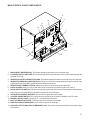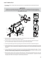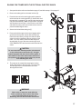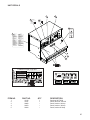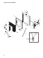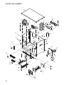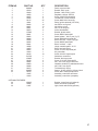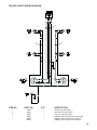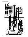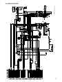
1
MLT 4250 OPERATING/PARTS MANUAL INTRODUCTION This manual provides information and procedures to safely operate and maintain the light tower and generator. For your own safety and protection from physical injury, carefully read, understand, and observe the safety instructions described in this manual. The information contained in this manual was based on machines in production at the time of publication. Magnum Products LLC reserves the right to change any portion of this information without notice. DO NOT MODIFY or use this equipment for any application other than which it was designed for. Magnum Products LLC recommends that a trained and licensed professional perform all electrical wiring and testing functions. Any wiring should be in compliance with the United States National Electric Code (NEC), state and local codes and Occupational Safety and Health Association (OSHA) guidelines. Keep a copy of this manual with the unit at all times. Additional copies are available from Magnum Products LLC, or can be found at www.m-p-llc.com. An engine operators manual was also supplied with the unit at the time of shipment from the factory. The manual provides detailed operation and maintenance procedures for the engine. Additional copies of the engine operators manual are available from the engine manufacturer. MAGNUM PRODUCTS LLC 215 Power Drive • Berlin, WI 54923 U.S.A. Phone: 920-361-4442 Fax: 920-361-4416 Toll Free: 1-800-926-9768 www.m-p-llc.com For technical or parts QUESTIONS, please contact Magnum Products’ Customer Support or Technical Support team at 920-361-4442. Please have your serial number available. To ORDER SERVICE PARTS, please contact the dealer from which your purchased the unit, or call Magnum Products to locate a dealer in your area. Engine Make: Engine Serial Number: Engine Model Number: Generator Make: Generator Model Number: Generator Serial Number: Unit Model Number: Unit Serial Number: WARNING CALIFORNIA PROPOSITION 65 WARNING: Diesel engine exhaust and some of its constituents are known to the state of California to cause cancer, birth defects and other reproductive harm. 2 TABLE OF CONTENTS Page INTRODUCTION ................................................................................................................. 2 TABLE OF CONTENTS ...................................................................................................... 3 SAFETY NOTES ................................................................................................................ 4 OPERATING SAFETY ........................................................................................................ 4 ENGINE SAFETY .............................................................................................................. 5 SERVICE SAFETY ............................................................................................................ 5 TOWING SAFETY .............................................................................................................. 6 REPORTING TRAILER SAFETY DEFECTS ....................................................................... 6 UNIT SERIAL NUMBER LOCATIONS ................................................................................. 6 SAFETY SYMBOL SUMMARY .......................................................................................... 7 SPECIFICATIONS ........................................................................................................ 8 - 9 EXTERIOR LOCATIONS ................................................................................................... 10 MAIN CONTROL PANEL COMPONENTS ........................................................................ 11 MAGNUM DIGITAL CONTROLLER (MDC) ................................................................ 12 - 13 GENERATOR MONITORING ............................................................................................ 13 ENGINE MONITORING ............................................................................................ 14 - 15 FINE VOLTAGE ADJUSTMENT ....................................................................................... 15 MDC CONTROLLER INFORMATION DISPLAYS, FUNCTIONS AND RESET .................... 16 MDC CONTROLLER - GENERATOR OPERATIONAL STATUS ......................................... 16 MDC CONTROLLER - ALARM MANAGEMENT ............................................................... 16 MDC CONTROLLER LIST OF POSSIBLE ALARMS WITH DESCRIPTIONS .............. 17 - 18 MDC CONTROLLER - HISTORY ...................................................................................... 18 ADJUSTING THE DISPLAY BACKLIGHTING .................................................................... 19 RESETTING THE “TIME TO SERVICE” REMINDER ......................................................... 19 GENERATOR OUTPUT CONNECTION LUGS .................................................................. 20 VOLTAGE SELECTOR SWITCH ...................................................................................... 21 AUXILIARY OUTLETS ...................................................................................................... 22 VOLTAGE REGULATION .................................................................................................. 22 EMERGENCY STOP SWITCH ........................................................................................ 22 MAIN CIRCUIT BREAKER ................................................................................................ 23 REMOTE START TERMINAL BLOCK ............................................................................... 23 TRANSFER SWITCH ................................................................................................ 23 - 24 LIGHT TOWER SET-UP ................................................................................................... 25 RAISING THE TOWER ..................................................................................................... 26 RAISING THE TOWER WITH OPTIONAL ELECTRIC WINCH ........................................... 27 LIGHT TOWER START UP ............................................................................................... 28 PRE-START CHECKLIST ................................................................................................. 28 MANUAL STARTING OF THE GENERATOR ............................................................. 28 - 30 AUTO (REMOTE) STARTING OF THE GENERATOR ....................................................... 30 LIGHT OPERATION .......................................................................................................... 31 SHUTTING DOWN THE GENERATOR ............................................................................. 31 LOWERING THE TOWER ................................................................................................ 32 LOWERING THE TOWER WITH OPTIONAL ELECTRIC WINCH ...................................... 32 REMOVING THE LIGHTS FOR TRANSPORTATION ......................................................... 33 TOWING THE TRAILER ................................................................................................... 33 TRAILER WHEEL BEARINGS ......................................................................................... 33 LIFTING THE TRAILER ..................................................................................................... 34 GENERAL MAINTENANCE .............................................................................................. 34 ENGINE MAINTENANCE ................................................................................................. 35 OPTIONAL LOWER RADIATOR HOSE HEATER USE AND MAINTENANCE ................... 35 DERATING FOR ALTITUDE .............................................................................................. 36 TROUBLESHOOTING SHUTDOWN CONDITIONS ........................................................... 36 TROUBLESHOOTING THE LIGHTS ................................................................................. 37 UNIT DECALS ........................................................................................................... 38 - 41 MANUAL WINCH MAST ASSEMBLY ........................................................................ 42 - 43 ELECTRIC WINCH MAST ASSEMBLY ...................................................................... 44 - 45 FRAME AND COMPONENTS ................................................................................... 46 - 48 GENERATOR ASSEMBLY ............................................................................................... 49 MAST JUNCTION BOX ASSEMBLY - HARD WIRED LIGHTS ........................................... 50 MAST JUNCTION BOX ASSEMBLY - QUICK DISCONNECT LIGHTS ............................... 51 ENCLOSURE ASSEMBLY ........................................................................................ 52 - 53 AUXILIARY OUTLET PANEL ASSEMBLY .................................................................. 54 - 55 AUXILIARY OUTLET PANEL OPTIONS ..................................................................... 56 - 57 LIGHT ASSEMBLY .................................................................................................... 58 - 59 ENGINE COOLING ASSEMBLY ................................................................................ 60 - 61 ENGINE ASSEMBLY ................................................................................................ 62 - 63 CONTROL PANEL ASSEMBLY ................................................................................. 64 - 65 CONTROL BOX ASSEMBLY ..................................................................................... 66 - 67 LUG DOOR ASSEMBLY .................................................................................................. 68 WIRING DIAGRAMS ................................................................................................. 69 - 75 3 SAFETY NOTES This is the safety alert symbol. It is used to alert you to potential personal injury hazards. Obey all safety messages that follow this symbol to avoid possible injury or death. This manual contains DANGERS, WARNINGS, CAUTIONS, NOTICES and NOTES which must be followed to prevent the possibility of improper service, damage to the equipment, personal injury or death. The following formatting options will apply when calling the readers attention to the DANGERS, WARNINGS, CAUTIONS, NOTICES and NOTES. DANGER INDICATES A HAZARDOUS SITUATION WHICH, IF NOT AVOIDED, WILL RESULT IN DEATH OR SERIOUS INJURY. WARNING Indicates a hazardous situation which, if not avoided, could result in death or serious injury. CAUTION Indicates a hazardous situation which, if not avoided, may result in minor or moderate injury. NOTICE Indicates a hazardous situation which, if not avoided, may result in property or equipment damage. Note: Notes contain additional information important to a procedure and will be found within the regular text body of this manual. OPERATING SAFETY Before using the light tower be sure you read and understand all of the instructions! This equipment was designed for specific applications; DO NOT modify or use this equipment for any application other than which it was designed for. Equipment operated improperly or by untrained personnel can be dangerous! Read the operating instructions and familiarize yourself with the location and proper use of all instruments and controls. Inexperienced operators should receive instruction from someone familiar with the equipment before being allowed to operate or set up the light tower. The following points should be practiced at all times: • • • • • • • • • • • • • • 4 The area immediately surrounding the light tower should be dry, clean, and free of debris. Position and operate the light tower on a firm, level surface. NEVER start a unit in need of repair. Lower tower when not in use, or if high winds or electrical storms are expected in the area. Make certain light tower is well grounded and securely fastened to a good earthen ground. The tower extends up to 30 ft. (9m). Make sure area above trailer is open and clear of overhead wires and obstructions. Bulbs become extremely hot in use! Allow bulb and light fixture to cool 10-15 minutes before handling. Keep area behind trailer clear of people while raising and lowering mast! NEVER raise, lower or turn mast while unit is operating! Trailer must be leveled and outriggers extended before raising tower. Outriggers must remain extended while tower is up. If for any reason any part of mast hangs up or winch cable develops slack while raising or lowering tower, STOP immediately! Contact an authorized service representative. NEVER remove safety pin or pull mast locking pin while tower is up! NEVER use tower if insulation on electrical cord is cut or worn through. NEVER operate lights without protective lens cover in place or with a lens cover that is cracked or damaged! ENGINE SAFETY Internal combustion engines present special hazards during operation and fueling! Failure to follow the safety guidelines described below could result in severe injury or death. Also read and follow all safety warnings described in the Engine Operator's Manual. A copy of this manual was supplied with unit when it was shipped from the factory. • • • • • • • • • • DO NOT run engine indoors or in an area with poor ventilation unless exhaust hoses are used. Diesel engine exhaust contains carbon monoxide, a deadly, odorless and colorless gas which, if inhaled, can cause nausea, fainting or death. Make sure engine exhaust cannot seep into closed rooms or ventilation equipment. DO NOT fill fuel tank near an open flame, while smoking, or while engine is running. DO NOT fill tank in an enclosed area with poor ventilation. DO NOT operate with the fuel tank cap loose or missing. DO NOT touch or lean against hot exhaust pipes or engine cylinders. DO NOT clean air filter with gasoline or other types of low flash point solvents. DO NOT remove engine coolant cap while engine is hot. DO NOT operate the unit without a functional exhaust system. Prolonged exposure to sound levels in excess of 85 DBA can cause permanent hearing loss. Wear hearing protection when working around a running engine. Keep area around exhaust pipes and air ducts free of debris to reduce the chance of an accidental fire. Batteries contain sulfuric acid which can cause severe injury or death. Sulfuric acid can cause eye damage, burn flesh or eat holes in clothing. Protective eye wear and clothing are necessary when working on or around the battery. Always disconnect the NEGATIVE (-) battery cable from the corresponding terminal before performing any service on the engine or other components. Shut the engine down if any of the following conditions exist during operation: 1. Noticeable change in engine speed. 2. Loss of electrical output. 3. Equipment connected to the generator overheats. 4. Sparking occurs. 5. Engine misfires or there is excessive engine/generator vibration. 6. Operating on a combustible surface. 7. Protective covers are loose or missing. 8. If the ambient air temperature is above 110° F. SERVICE SAFETY This unit uses high voltage circuits capable of causing serious injury or death. Only a qualified electrician should troubleshoot or repair electrical problems occurring in this equipment. • • • • • • • Before servicing light tower, make sure the engine start switch is turned to OFF, circuit breakers are open (off) and the negative terminal on the battery is disconnected. NEVER perform even routine service (oil/filter changes, cleaning, etc.) unless all electrical components are shut down. NEVER allow water to accumulate around the base of the light tower. If water is present, DO NOT service! NEVER service electrical components if clothing or skin is wet. If the unit is stored outside, check the engine and generator for any moisture and dry the unit before use. NEVER wash the unit with a power washer or high pressure hose. Open main circuit breaker before disconnecting battery cables. Keep hands, feet, and loose clothing away from moving parts on generator and engine. Make sure slings, chains, hooks, ramps, jacks, and other types of lifting devices are attached securely and have enough weight-bearing capacity to lift or hold the equipment safely. Always remain aware of the position of other people around you when lifting the equipment. 5 TOWING SAFETY Towing a trailer requires care! Both the trailer and vehicle must be in good condition and securely fastened to each other to reduce the possibility of an accident. Also, some states require that large trailers be registered and licensed. Contact your local Department of Transportation office to check on license requirements for your particular unit. • • • • • • • • Check that the hitch and coupling on the towing vehicle are rated equal to, or greater than, the trailer's "gross vehicle weight rating" (GVWR). Check tires on trailer for tread wear, inflation, and condition. Inspect the hitch and coupling for wear or damage. DO NOT tow trailer using defective parts! Make sure the trailer hitch and the coupling are compatible. Make sure the coupling is securely fastened to the vehicle. Connect safety chains in a crossing pattern under the tongue and attach the breakaway cable TO THE REAR BUMPER OF THE TOWING VEHICLE. Do not attach the cable to the trailer hitch. Make sure directional and brake lights on the trailer are connected and working properly. Check that all lug nuts holding wheels on are tight and that none are missing. Maximum recommended speed for highway towing is 45 m.p.h. Recommended off-road towing speed is not to exceed 10 m.p.h. or less depending on terrain. When towing, maintain extra space between vehicles and avoid soft shoulders, curbs and sudden lane changes. If you have not pulled a trailer before, practice turning, stopping, and backing up in an area away from heavy traffic. A film of grease on the coupler will extend coupler life and eliminate squeaking. Wipe the coupler clean and apply fresh grease each time the trailer is towed. REPORTING TRAILER SAFETY DEFECTS If you believe your trailer has a defect which could cause a crash or could cause injury or death, you should immediately inform the National Highway Traffic Safety Administration (NHTSA) in addition to notifying Magnum Products LLC. If NHTSA receives similar complaints, it may open an investigation; and if it finds that a safety defect exists in a group of vehicles, it may order a recall and remedy campaign. However, NHTSA cannot become involved in individual problem between you, your dealer, or Magnum Products LLC. To contact NHTSA, you may either call the Auto Safety Hotline toll-free at 1-888-327-4236 or by fax at: (202)-3667882. Additional contact information can be found at: www.nhtsa.dot.gov. UNIT SERIAL NUMBER LOCATIONS Refer to the locations illustrated below to find the unit ID tag, and trailer ID tag on your unit. Important information, such as the unit serial number, model number and Vehicle Identification Number (V.I.N.) for your trailer are found on these tags. Record the information from these tags, so it is available if the tags are lost or damaged. When ordering parts or requesting technical service information, you may be asked to specify this information. Unit ID Tag V.I.N. Tag MANUFACTURED BY/FABRIQUE PAR: GVWR/PNBV: GAWR/PNBE TIRE/PNEU RIM/JANTE Located on inside of panel. DATE OF MFG: COLD INFL. PRESS./PRESS. DE GONF A FROID KPA(PSI/LPC) SGL/DUAL THIS VIEHICLE CONFORS TO ALL APPLICABLE STANDARDS PRESCRIBED UNDER THE CANADIAN MOTOR VIEHICLE SAFETY REGULATIONS IN ECCEFT ON THE DATE OF MANUFACTURE. / CE VEHICULE EST CONFORME A TOUTES LES NORMES QUI LUI SONT APPLICABLES EN VERTU DU REGLEMENT SUR LA VEHICULES DES AUTOMOBILES DU CANADA EN VIGUEUR A LA DATE SA FABRICATION. TM THIS VIEHICLE CONFORMS TO ALL APPLICABLE U.S. FEDERAL MOTOR VEHICLE SAFETY STANDARDS (FMVSS) IN EFFECT ON THE DATE OF MANUFACTURE SHOWN ABOVE. V.I.N./N.I.V.: 215 Power Drive Berlin, WI 54923 1-800-926-9768 Model Serial Number Mfg. Code kg lbs rpm hz RATING: amb. temp. CONT. STAND BY 1 Phase 3 Phase KW V KVA V A A FOR ELECTRICAL EQUIPMENT ONLY. POUR MATERIAL ELECTRIQUE SEULEMENT. ® LR 114630-1 TM PRODUCTS LLC MADE IN USA 215 Power Drive Berlin, WI 54923 1-800-926-9768 Model Serial Number Mfg. Code kg lbs rpm hz RATING: amb. temp. CONT. STAND BY 1 Phase 3 Phase KW V KVA V A A FOR ELECTRICAL EQUIPMENT ONLY. POUR MATERIAL ELECTRIQUE SEULEMENT. ® LR 114630-1 MANUFACTURED BY/FABRIQUE PAR: GVWR/PNBV: GAWR/PNBE TIRE/PNEU RIM/JANTE DATE OF MFG: COLD INFL. PRESS./PRESS. DE GONF A FROID KPA(PSI/LPC) SGL/DUAL THIS VIEHICLE CONFORS TO ALL APPLICABLE STANDARDS PRESCRIBED UNDER THE CANADIAN MOTOR VIEHICLE SAFETY REGULATIONS IN ECCEFT ON THE DATE OF MANUFACTURE. / CE VEHICULE EST CONFORME A TOUTES LES NORMES QUI LUI SONT APPLICABLES EN VERTU DU REGLEMENT SUR LA VEHICULES DES AUTOMOBILES DU CANADA EN VIGUEUR A LA DATE SA FABRICATION. THIS VIEHICLE CONFORMS TO ALL APPLICABLE U.S. FEDERAL MOTOR VEHICLE SAFETY STANDARDS (FMVSS) IN EFFECT ON THE DATE OF MANUFACTURE SHOWN ABOVE. V.I.N./N.I.V.: 6 PRODUCTS LLC MADE IN USA TYPE/TYPE DE VEHICULE: TYPE/TYPE DE VEHICULE: SAFETY SYMBOL SUMMARY This equipment has been supplied with numerous safety and operating decals. These decals provide important operating instructions and warn of dangers and hazards. Replace any missing or hard-to-read decals and use care when washing or cleaning the unit. Decal placement and part numbers can be found in the beginning of the parts section of this manual. Below is a summary of the intended meanings for the symbols used on the decals. UV Safety alert symbol; Used to alert you to potential personal injury hazards. Asphyxiation hazard; Operate in well ventilated area. Hot surface(s) nearby. Dangerous voltage may be present. Belt/entanglement hazard; Keep body parts clear of this area. Anchor/tie down point. Fan hazard; Keep body parts clear of this area. Forklift here only. Crush hazard; Keep body parts clear of this area. Use clean diesel fuel only. Ultraviolet radiation hazard; Operate only with lens intact. Burn/scald hazard; pressurized steam. Stop engine before fueling. Read and understand the supplied operator’s manual before operating unit. Fire/explosion hazard; Keep open flames away from unit. Unit electrical ground. Lift here only. 7 SPECIFICATIONS Read this manual carefully before attempting to use this light tower. The potential for property damage, personal injury or death exists if this equipment is misused or installed incorrectly. Read all of the manuals included with this unit. Each manual details specific information regarding items such as set up, use and service requirements. Specifications are subject to change without notice. MAGNUM MODEL MLT 4250 Engine Make/Brand ........................................................ Isuzu Model .................................................................. 4LE1-NYGV-01 Type .................................................................... Diesel, liquid cooled, 4-stroke Horsepower - prime hp (kW) ............................... 31.5 (23.5) Horsepower - standby hp (kW) ........................... 34.5 (25.7) Operating Speed rpm ......................................... 1800 Displacement in3 (L) ........................................... 134.25 (2.20) Cylinders - qty .................................................... 4 Fuel Consumption - 100% prime gph (Lph) ....... 1.80 (6.81) Battery Type - Group Number ............................. 24 Battery Voltage (Quantity per Unit) ..................... 12V (1) Battery Rating ..................................................... 720 CCA Generator Make/Brand ........................................................ Marathon Electric Model .................................................................. 282NSL1505 Type, Insulation ................................................... Brushless, H Generator Set (Engine/Generator) 3Ø - Standby kW (kVA) ...................................... 20 (25) Amps - 3Ø Standby - 480 (208V) A ..................... 30 (69) 3Ø - Prime kW (kVA) .......................................... 18 (23) Amps - 3Ø Prime - 480 (208V) A ........................ 28 (64) 1Ø - Standby - kW (kVA) .................................... 16.0 (16.0) Amps - 1Ø Standby - 240V A .............................. 67 1Ø - Prime - kW (kVA) ........................................ 15.0 (15.0) Amps - 1Ø Prime - 240V A ................................. 63 Frequency Hz ..................................................... 60 Power Factor ...................................................... 1 (1Ø), 0.8 (3Ø) Dimensions Length w/ mast stowed in (m) ............................ Width in (m) ....................................................... Width w/ outriggers extended in (m) ................... Height w/ mast stowed in (m) ............................. Maximum height of tower ft (m) .......................... 170 (4.32) 63 (1.60) 140 (3.56) 70 (1.78) 30 (9.14) Weights Dry Weight lbs (kg) ............................................. 2158 (979) Operating Weight lbs (kg) ................................... 2556 (1159) Capacities Fuel Tank Volume gal (L) ................................... Usable Fuel Volume gal (L) ................................ Coolant (incl. engine) qt (L) ................................. Oil (incl. filter) qt (L) ............................................ Maximum Run Time hrs ...................................... 8 56 (212) 56 (212) 11.6 (11.0) 8.6 (8.1) 31 SPECIFICATIONS Read this manual carefully before attempting to use this light tower. The potential for property damage, personal injury or death exists if this equipment is misused or installed incorrectly. Read all of the manuals included with this unit. Each manual details specific information regarding items such as set up, use and service requirements. Specifications are subject to change without notice. Lighting Lighting Type ....................................................... Metal Halide Ballast Type ........................................................ Coil & Core Lumens ............................................................... 440,000 Coverage acres (m2) ........................................... 5 - 7 (20,234 - 28,328) AC Distribution Circuit Breaker Size ............................................ Voltage Selection ................................................ Voltage Regulation .............................................. Voltages Available 1Ø ......................................... Voltages Available 3Ø ......................................... 90 3 Position Switch (lockable) +/-1% 120, 139, 208, 220, 240, 277 208, 220, 440, 480 Trailer Number of Axles ................................................. Capacity - Axle Rating lbs (kg) ........................... Tire Size in ......................................................... Hitch - Standard .................................................. Maximum Tire Pressure psi ................................ 1 3000 (1361) 15 2" Ball 50 9 EXTERIOR LOCATIONS 2 1 3 4 5 6 1. FUEL FILLER LOCATION (under door): Use clean DIESEL FUEL ONLY. 2. RADIATOR ACCESS PANEL: Remove this panel for engine coolant service. 3. CONTROL PANEL LOCATION (under door): Engine/generator controls and all circuit breakers. 4. EMERGENCY STOP SWITCH: For emergency shutdown; stops engine and trips main circuit breaker. 5. EQUIPMENT OUTLETS: Circuit breaker protected outlets; 20, 30 and/or 50 amp ratings. 6. GROUND STUDS (2): For grounding generator and equipment connected to the equipment outlets. 10 MAIN CONTROL PANEL COMPONENTS 9 8 10 11 12 13 2 7 6 1 5 4 2 3 1. MAIN CIRCUIT BREAKER (90A): This breaker will disconnect power to the connection lugs. 2. LUG DOOR SAFETY SWITCHES: These switches will shut the generator down if the lug door is opened when the generator is running. 3. GENERATOR OUTPUT CONNECTION LUGS: These allow appropriate loads to be wired directly to the generator. 4. GENERATOR GROUND CONNECTION LUG: This lug is for connecting a good earthen ground per any local, state or National Electric Code (NEC) guidelines before starting the generator. 5. REMOTE START TERMINAL BLOCK: Allows connections for remote starting of the generator. 6. CABLE ACCESS: Allows for entry of load cables to the connection lugs with the lug box door closed. 7. PHASE SELECTOR SWITCH: This switch will change the generator output between three phase and single phase power. See the VOLTAGE SELECTOR SWITCH section for more information. 8. VOLTAGE ADJUSTMENT RHEOSTAT: Used to fine tune generator output voltage. 9. CONTROL POWER SWITCH: This is the main power switch for the controller in MANUAL or AUTO mode. 10. ENGINE CONTROL PANEL: See pages 12 - 13 for additional information. 11. BALLAST INDICATOR LIGHTS: Indicates power from the ballast to each light. 12. INDIVIDUAL CIRCUIT BREAKERS: One breaker is supplied for each light. 13. AUXILIARY OUTLET MAIN CIRCUIT BREAKER (100A): This breaker disconnects power to the auxiliary equipment outlets. 11 MAGNUM DIGITAL CONTROLLER (MDC) The Magnum Digital Controller (MDC) is an enhanced digital generator controller used to start, stop and monitor the operation of the generator and the engine. The controller constantly monitors vital generator and engine functions for a number of pre-programmed alarm and fault conditions. When a fault condition occurs, the engine will shut down automatically and the Liquid Crystal Display (LCD) window will display the fault that caused the shutdown; to resume operation the fault condition must be resolved. The controller has the ability to provide the display readout in English and Spanish; other languages are available. A screen print out of the display screen is also available. This controller also records a “History” of the unit’s performance which may be viewed at any time and will not be removed or lost when the controller is powered down. 2 3 1 MAN AUT Ready PF RPM 0 kW 0.00 0 0 4 5 The MDC panel consists of five sections, including: the “CONTROL ON” / “CONTROL OFF” Toggle Switch and Fine Voltage Adjustment Screw; the “OPERATION” keypad; the LCD window; the “DIAGNOSTICS” keypad; and the “STATUS” Light Emitting Diodes (LED’s). The following is a brief summary of the operation of each section of the control panel: 1. The “CONTROL ON” / “CONTROL OFF” Toggle Switch and Fine Voltage Adjustment Screw • Control On/Off Toggle Switch This toggle switch powers-up the control panel and the controller. • Fine Voltage Adjustment Screw This screw may be adjusted to set the generator output voltage after the voltage selector switch has been changed from one phase to another. This adjustment must be accomplished within 45 seconds of start-up so that the unit does not experience a shut down alarm for “SENSING”. 2. The “OPERATION” Keypad • “ENGINE START” Button The Power Screen Display must be in the “MAN” mode in the upper left corner of the LCD window and the “Ready/Manual” LED lit in the “Status” portion of the controller. Press the green “ENGINE START” button to start the unit. • “ENGINE STOP” Button Press the red “ENGINE STOP” button to shut down the unit and start the “Stop Value” timer. • “MANUAL W” Button Press this button to change from the Automatic (Remote) starting mode to Manual starting mode. • “AUTO X” Button Press this button to change from Manual starting mode to Automatic (remote) starting mode. 12 • • “ALARM CANCEL” Button When an alarm is activated, either visually or audibly, press this button to silence or cancel the alarm. “FAULT RESET” Button Press this button to clear the fault from the LCD window after the fault has been corrected. Press “FAULT RESET” and “ENTER” to clear the John Deere ECU Alarm List Codes. 3. The Liquid Crystal Display (LCD) • This window will toggle between the Generator Display Screen and the Engine Display Screen upon startup of the unit. By viewing these screens, the operator will be able to monitor both the engine and generator status while the unit is running. 4. The “DIAGNOSTICS” Keypad • “S” Scroll-Up Button Press this button to scroll-up within the LCD window. • “T” Scroll-Down Button Press this button to scroll-down within the LCD window. • “PAGE SELECT” Button Pressing this button will select the next display screen. • “ENTER” Button Pressing this button will place you inside the particular display to review the generators preprogrammed setpoints or parameters. 5. The “STATUS” Light Emitting Diodes (LED’s) • These 6 LED’s will illuminate to display the current operational status of the generator; - Alarm/Fault: Indicates active or inactive alarms, but not reset shutdown alarms. - Warning: Indicates an active or inactive alarm, or a warning alarm that has not been reset - Ready/Manual: Indicates the controller is ready to start and in the manual mode. - Ready/Auto: Indicates the unit is in the “AUTO” mode ready for the remote start signal. - Running: Indicates the unit is running. - Supplying Load: Indicates a load is being applied to the generator. GENERATOR MONITORING Generator information is shown on the Liquid Crystal Display (LCD) window in a toggling manner with the Engine information after the first 60 seconds of operation, then every five seconds thereafter. The generator display screen will show frequency, line to neutral voltage, line to line voltage and amperage. Note: When loading the generator, it is important to observe the amperage to determine the load balance on each line of the generator. Minor load unbalances, usually 5% or less, will not cause any particular problems. Every effort should be made to distribute the load equally between all lines. • • • • Hertz: Displays output frequency. Generator Output Voltage: Line to Neutral display, single phase (1Ø). Generator Output Voltage: Line to Line display, 3 phase (3Ø). Amps: Displays the AC output amperage produced by the generator. 13 ENGINE MONITORING Engine information is shown on the Liquid Crystal Display (LCD) window in a toggling manner with the Generator information after the first 60 seconds of operation and then every 5 seconds thereafter. The engine display screen will show oil pressure, engine coolant temperature, fuel level and battery voltage. • • • • Oil Press: Displays engine oil pressure. The display registers oil pressure between 0-100 psi. Normal operating pressure is between 35-80 psi. Eng Temp: Displays the temperature of the engine’s coolant. If the coolant temperature exceeds the Maximum Water Temperature of 230° F the engine will automatically shut down. Zero “0” will be displayed until a minimum temperature of 100° F is reached. Fuel Level: Displays the relative fuel level in the fuel tank in percent (50% = 1/2 tank, 75% = 3/4 tank, etc.). If the fuel level drops below a programmed low fuel point – usually at 15%, a low fuel warning and optional audio alarm will be activated. If the fuel level drops below the programmed low fuel limit, usually at 5%, the engine will automatically shut down. (Note: The MLG 25 does not display fuel level). Vbat: Displays the engine battery voltage. A normal reading is 13-14V on 12 volt systems and 24-26 on 24 volt systems, (with the engine running). Additional information may be viewed while the unit is in “MANUAL” or “AUTO” mode. By pressing the “Page Select” button, the operator will select one of the following screens; “Running” screen, “Password” screen, or “History” screen. In each of these page selections the operator may press the “S” or “T” buttons on the “DIAGNOSTICS” keypad to display additional information as follows: 14 • “Running” screen: The operator may press the “S” or “T” buttons on the “DIAGNOSTICS” keypad to display the “Alarm List” screen, “ECU Alarm List” screen, “Run Hours” screen, “ECU Values” screen, Engine display screen and Generator display screen. • “Password” screen: The operator may press the “S” or “T” buttons on the “DIAGNOSTICS” keypad to move the “>” cursor up or down a list of text. • “History” screen: The operator may press the “S” or “T” buttons on the “DIAGNOSTICS” keypad to move the “>” cursor up or down a list of the latest alarm or shutdown codes. Pressing the “Enter” button at a particular selection will allow the operator to scroll to the right in the LCD window to view the generator operating parameters at the time of the alarm or shutdown. The history of alarms or codes of the unit are saved in the digital controller. The most recent alarm or code is the first to be listed, with the time/date of the alarm or code at the bottom of the screen. The controller stores up to 118 codes. When full, the controller will automatically remove the oldest file. These codes will not be lost when the control power toggle switch is powered off. FINE VOLTAGE ADJUSTMENT Upon start-up of the generator, the “Running” screen of the Magnum Digital Controller (MDC) will display “SENSING” and will countdown from 45 seconds to “0” Zero. This is a safety feature of the controller to protect the generator from over or under voltage upon start-up. VOLTAGE ADJUSTMENT RHEOSTAT CONTROL ON CONTROL OFF “SENSING” is a 45 second time delay and count down process before the MDC records the generator nominal output voltage. This nominal generator voltage is then compared to the current set point voltage of the voltage selector switch. If the nominal voltage recorded by the controller is greater than or lower than the current set point voltage of the voltage selector switch setting by 10% or more, the controller will shut the generator down automatically. The display will read: Wrn VG1 or 2 or 3 Under/Over and/or Sd Vg1 or 2 or 3 Under/Over. This means the controller warned (“Wrn”) or even shut down (“Sd”) the unit due to an output voltage irregularity. The output voltage of the generator may be adjusted after the generator is running by use of the fine voltage adjustment screw. The adjusting screw is located directly below the control On/Off toggle switch on the control panel. This screw turns a rheostat that will provide an increase (“+”) or a decrease (“-”) in the generator output voltage as displayed on the Power Display Screen on the control panel. When making this adjustment, if the voltage is increased or decreased too fast or too slow, the unit will automatically shut down. This adjustment needs to be made within the 45 second delay and countdown to “0” Zero period. To adjust the output voltage, check the output voltage on the Liquid Crystal Display (LCD) window labeled Gen freq & Hz. Look at the L1N voltage or the L12 voltage on the display. The generator nominal output voltage should be within 10% of the voltage rating on the voltage selector switch. To adjust the output voltage loosen the lock nut at the base of the screw and turn the screw in the desired direction until the required voltage shown on the LCD window matches the stated voltage on the voltage selector switch. For Example: With the voltage selector switch set to “208/120V” 3 Phase position, the voltage displayed on the Gen freq & Hz screen must be within ± 10 % of the 208/120 position (188-228 V Line to Line / 108-132 V Line to Neutral). If the voltage is not set within 10% of the applied voltage or the voltage is not reset within the 45 second delay period, the generator will shut down automatically and the display will read Wn VG1 or 2 or 3 Under/Over and/or Sd Vg1 or 2 or 3 Under/Over. Note: Each time the voltage selector switch is changed from one setting to another, an adjustment will need to be made to the fine voltage using this adjustment screw. 15 MAGNUM DIGITAL CONTROLLER (MDC) INFORMATION DISPLAYS, FUNCTIONS AND RESET The Magnum Digital Controller (MDC) constantly monitors vital generator and engine functions for a number of operation, alarm and fault conditions. When a fault condition occurs, the engine will shut down automatically and the Liquid Crystal Display (LCD) window will show the fault that has caused the shut down. To resume operation, the fault condition must be resolved. To reset the controller and resume operation, press the “FAULT RESET” button. MAGNUM DIGITAL CONTROLLER (MDC) – GENERATOR OPERATIONAL STATUS The Magnum Digital Controller (MDC) displays the operational status of the generator using the following codes: No. 1 2 3 4 5 Engine State Machine AfterCool Cooling Cranking EmergMan Init 6 7 8 9 10 11 12 13 14 Loaded Not Ready Pause Prestart Ready Running Shutdown Starting Stop No. 1 Electrical State Machine StabilTO Description Engine aftercooling, Cooling Pump output is closed. The generator is cooling before stop. Engine is cranking. Emergency Manual gen-set operation. Autotest during controller power on. The generator is running at nominal speed and GCB OPEN/CLOSE is closed. The generator is not ready to start. Pause between start attempts. Prestart sequence in process, Prestart output is closed. The generator is ready to run. The generator is running at nominal speed. Shut-down alarm is activated. Starting speed is reached and the Idle timer is running. Stop Description Stabilization Timeout MAGNUM DIGITAL CONTROLLER (MDC) - ALARM MANAGEMENT The Magnum Digital Controller (MDC) is capable of displaying the following alarms: No. Type 1 2 Sensor fail (FLS) Warning (WRN) 3 Shut down (SD) 16 Description Sensor fail is detected when measured value is 6% out of the selected characteristic. Sensor fail indicated by ##### symbol instead measured value. When warning comes up, see list of possible alarms. When the shut-down alarm comes up the Magnum Digital Controller opens outputs GCB CLOSE/OPEN, FUEL, SOLENOID, STARTER AND PRESTART to stop the engine immediately. MAGNUM DIGITAL CONTROLLER (MDC) - LIST OF POSSIBLE ALARMS/DESCRIPTIONS Shut down and warning fault conditions and the displayed message are described in the following table: No. Events Specification Protection Type Information on Binary Output Available Description SD YES Shutdown alarm configurable on the input of IG-IOM/IGS-PTM. WRN YES SD YES Warning alarm configurable on the input of IG-IOM/IGS-PTM. If the controller switches off during starting sequence due to bad battery condition it doesn't try to start again and activates this protection. Configurable WRN YES YES 1 AnInIOM Sd 2 AnInIOM Wrn 3 Battery Flat 4 5 Binary Input ChrgAlternFail 6 EmergencyStop SD NO Failure of the alternator for charging the battery. If the input Emergency stop is opened shutdown is immediately activated. 7 Engine Temp Sd SD NO Water temperature is greater than Sd Water temp setpoint. 8 Engine Temp Wrn WRN YES 9 10 11 12 13 14 15 16 Fgen <, > Fuel Level Sd Fuel Level Wrn GCB fail Igen unbl Low BackupBatt Oil Press Sd Oil Press Wrn SD SD WRN SD SD WRN SD WRN YES YES YES NO NO NO NO YES Water temperature is greater than Wrn Water temp setpoint. The generator frequency is out of limits given by Gen >f and Gen <f setpoints. 17 Overload SD YES 18 Overspeed SD YES The load is greater than the value given by Overload setpoint. The protection comes active if the speed is greater than Overspeed setpoint. NONE NO Wrong checksum of parameters. Happens typically after downloading new firmware or changing of the parameter. The controller stays in INIT mode. Check all parameters write at least one new parameter. SD NO SD WRN SD SD NO NO YES YES WRN YES 19 ParamFail 20 PickupFault 21 22 23 24 Sd IOM fail SprinklActive Start failed Stop fail 25 Ubat 26 Underspeed SD YES 27 Vgen <, > SD YES Configurable Warning/Shutdown alarms on the inputs of IL-NT. Fuel level is less than Sd Fuel Level setpoint. Fuel level is less than Wrn Fuel Leve l setpoint. Failure of the generator circuit breaker. The generator current is unbalanced. RTC backup battery is flat. Oil pressure is less than Sd Oil press setpoint. Oil pressure is less than Wrn Oil press setpoint. Failure of the magnetic pick-up sensor for speed measurement. Shutdown alarm in case of lost connection to IG-IOM/IGS-PTM module. The protection is active if the output Sprinkler is closed. Gen-set start failed Gen-set stop failed. Battery voltage is out of limits given by Batt overvolt and Batt undervolt setpoints. During starting of the engine when the RPM reaches the value of Starting RPM setpoint the starter is switched off and the speed of the engine can drop under Start RPM again. Then the Underspeed protection becomes active. Protection evaluation starts 5 sec The generator voltage is out of limits given by Gen <V and Gen >V setpoints. 17 28 Vgen unbal 29 Wrn ECU Alarm SD WRN NO NO 30 Wrn RA15 fail WRN NO 31 WrnServiceTime WRN NO The generator voltage is unbalanced more than the value of Volt unbal setpoint. ECU alarm list is not empty. Warning alarm in case of lost connection to IGL-RA15 module. The period for servicing is set by the NextServTime setpoint. The protection comes active if the running hours of the engine reach this value. MAGNUM DIGITAL CONTROLLER (MDC) – HISTORY The Magnum Digital Controller (MDC) controller stores a record of each important event into the history file of the controller. The history file seats 118 records. When the history file is full, the oldest records are removed. No. 1 2 3 4 5 6 7 8 9 10 11 12 13 14 15 16 17 18 19 20 21 22 23 24 25 26 27 28 29 18 Record Structure Abbreviation AIM1 AIM2 AIM3 AIM4 BIM BIN BOM BOUT Date EngT FC FLvl FMI Gfrg Ig1 Ig2 Ig3 LChr Num OilP PF Pwr Reason RPM Time Ubat Vg1 Vg2 Vg3 Historical value IG-IOM, IGS-PTM Analog input 1 value (when configured IG-IOM, IGS-PTM) IG-IOM, IGS-PTM Analog input 2 value (when configured IG-IOM, IGS-PTM) IG-IOM, IGS-PTM Analog input 3 value (when configured IG-IOM, IGS-PTM) IG-IOM, IGS-PTM Analog input 4 value (when configured IG-IOM, IGS-PTM) IG-IOM, IGS-PTM Binary inputs (when configured IG-IOM, IGS-PTM) Binary inputs IL-NT IG-IOM, IGS-PTM Binary outputs (when configured IG-IOM, IGS-PTM) Binary inputs IL-NT Date of historical event in format DD/MM/YY IL-NT Analog input 2 value (default Water temperature) ECU alarm FailureCode IL-NT Analog input 3 value (default Fuel level) ECUalarm Failure Mode Identifier Generator frequency Generator current L1 Generator current L2 Generator current L3 Character of the load Number of historical event IL-NT Analog input 1 value (default Oil pressure) Generator PF Generator active power Event specification Engine Speed Time of historical event in format HH:MM:SS Battery voltage Generator voltage L1 Generator voltage L2 Generator voltage L3 ADJUSTING THE DISPLAY BACK LIGHTING The backlighting on the Liquid Crystal Display (LCD) window may be adjusted brighter or darker by the operator whenever the Magnum Digital Controller (MDC) is powered up. 1. Press and hold “Enter” and press “S” or “T” on the Diagnostics keypad to increase or decrease the display contrast as needed. 2. Release the “Enter” button and the “S” or “T”buttons when the desired backlighting is attained. Note: Anytime an “*” is displayed on the LCD, the text or set point cannot be changed with out the use of a password. Contact Magnum Products Technical Support for assistance. RESETTING OF THE “TIME TO SERVICE” REMINDER The Magnum Digital Controller (MDC) will display the message “ WrnServiceTime” when the unit is due for maintenance or service. The maintenance or service interval is set at 250 hours of engine running time. Once the unit has been serviced, the “ServiceTime” reminder needs to be reset to the 250 hour interval. The following procedure demonstrates how to reset the running hours to 250: 1. With the unit shut down, power up the controller with the “Control On/Off” Toggle Switch. The initialization screen will be displayed. The controller will toggle automatically to the “Ready” Display screen. 2. Press the “S” button. The “Alarm List” display screen will appear. The next screen will display lines of text; starting with the word “Password”, then “Basic Settings”, “Engine Params”, “Engine Protect” etc. The top line has a “> “ cursor before the word ‘Password”. 3. Press the “T” button to move the “> “cursor down to the “Engine Protect” line of text. 4. Press Enter. “NextServTime” will appear at the top of the display screen on the left side, with the current service time hour setting (250) one line below on the right side 5. Press Enter. The current run time in hours will now appear on the left side of the display screen, directly under “NextServTime” 6. Press the “S” button and reset the current run time hour setting to 250. If you overshoot the 250 time interval use the “T” button to get back to the 250 time interval. 7. Press “Enter” to save the current run time hour setting. 8. Move the “CONTROL ON / I” toggle switch to the “CONTROL OFF / O” position. 19 GENERATOR OUTPUT CONNECTION LUGS The generator is equipped with connection lugs behind a door below the controller face. The lugs provide connection points for attachment of external loads to the generator. A large decal on the inside of the connection lug door details the proper connections for selected voltages. WARNING It is HIGHLY RECOMMENDED that only a trained and licensed electrician perform any wiring and related connections to the generator. Installation should be in compliance with the National Electric Code (NEC) as well as any local or state guidelines as required by law. Failure to follow proper installation requirements may result in equipment or property damage, personal injury or death. WARNING Before any connections are made to the generator, make sure that the main circuit breaker and the control power switch are in the OFF “O” position. Potentially lethal voltages may be present at the generator connection lugs. DANGER IMPROPER OR INCORRECT CONNECTIONS TO A BUILDINGS ELECTRICAL SYSTEM CAN CAUSE POTENTIALLY LETHAL VOLTAGE TO BACKFEED ONTO UTILITY LINES. THIS MAY RESULT IN INJURY OR ELECTROCUTION TO UTILITY WORKERS NEARBY. MAKE SURE THE GENERATOR IS SUPPLYING POWER TO AN ISOLATED OBJECT OR BUILDING THAT IS NOT CONNECTED TO ANY UTILITY LINES. Connections to the lugs should be made by running the power cables through the circular plastic bushing on the lower right side of the control box. DO NOT make any connections directly to the lugs without routing the cables through this bushing. The lug door is equipped with safety interlock switches that will automatically trip the main circuit breaker and disable the voltage regulator when the lug door is opened. Use a hex-wrench to tighten the cable connections. WARNING Never attempt to disable or modify the lug door safety switches. Equipment damage, personal injury or death may result. A ground connection is located next to the connection lugs. The unit MUST HAVE this ground lug connected to a good earthen ground for proper operating safety. The ground connection should be in compliance with the National Electric Code (NEC) as well as any state or local guidelines or codes. 20 TIGHTEN CONNECTION LUGS WITH A HEX WRENCH VOLTAGE SELECTOR SWITCH The voltage selector switch is located behind the lug door, underneath the engine controller panel. The selector switch is a three position switch that mechanically changes the connections between the generator output leads and the connection lugs. Voltage ranges are selected by rotating the handle on the switch to the desired voltage. NOTICE Never change the voltage selector switch while the engine is running! This will cause sever arcing and damage to the switch and generator windings. L1 208 120 480/277V 3-PHASE L1 - L2 = 480V L1 - N = 277V L2 - L3 = 480V L2 - N = 277V L3 - L1 = 480V L3 - N = 277V N= T1 T4 T7 480 277 L-L T10 T12 N T11 T9 T8 T5 T6 T2 T3 L3 L2 L-N L1 - L2 = 208V L1 - N = 120V L2 - L3 = 208V L2 - N = 120V L3 - L1 = 208V L3 - N = 120V N= L1 208 120 208/120V 3-PHASE 240 120 480 277 T7 T1 T10 T4 N T12 T9 L3 T6 L-L T5 T2 T11 T3 T8 L2 L-N T6 L1 - L3 = 240V L2 - N = ------L1 - N = 120V L3 - N = 120V T8 208 120 T12 T2 T3 T11 T10 T7 T4 T1 N 240/120V 1-PHASE 240 120 L3 L1 T5 T9 120V 120V 240V The voltage switch is equipped with a locking mechanism. Once the proper voltage has been selected, push the red latch on the inside of the phase switch handle up and insert a padlock through the handle. By locking the handle in place you will prevent unauthorized personnel from changing the switch settings. Note: When the voltage selector switch is in position for 480/277V 3Ø, voltage at the two GFCI duplex convenience outlets is 139 Volts and the voltage at the three twist-lock outlets is 240/139 Volts. When the voltage selector switch is in position for 208/120V 3Ø, voltage at the three twist-lock outlets and the two GFCI outlets is 208/120 Volts. 21 AUXILIARY OUTLETS The control panel is equipped with six outlets for running accessories or tools from the generator. Power is supplied to the outlets any time the engine is running and the main circuit breaker and the auxiliary outlet main circuit breaker are switched in the ON “I” position. AUXILIARY OUTLET GROUNDING STUD Should the main breaker trip, or the auxiliary outlet main circuit breaker trip, remove some of the load to the outlets before turning them back on. Note: To ensure proper grounding, anytime the generator is providing power to any equipment or load panels that do not have a grounded plug, a ground wire must be added between the equipment and the grounding stud on the outlet panel per any local, state or NEC codes and guidelines. VOLTAGE REGULATION The electronic voltage regulator controls the output of the generator by regulating the current into the exciter field. The regulator has three screwdriver adjustable potentiometers that may be adjusted for voltage, stability and under frequency (U/F). The voltage regulator on your unit is adjusted before shipment from the factory. Contact Magnum Products LLC for additional information before attempting to adjust the voltage regulator. EMERGENCY STOP SWITCH The generator is equipped with one emergency stop switch, located on the side panel next to the auxiliary outlet panel. The switch is clearly labeled with “EMERGENCY STOP” and is red in color. The switch can be accessed and activated with all doors closed and locked. Activate the emergency stop switch by pushing the red button in until it locks down. This will trip the main circuit breaker which will open the contact disconnecting the load to the connection lugs. This will also open the fuel circuit, shutting down the engine and the Emergency Stop fault will be displayed on the LCD. The switch will remain closed until it is pulled out. Note: Use the EMERGENCY STOP only when the generator must be shut down immediately. For any other shut down, follow the detailed shut down procedure. 22 MAIN CIRCUIT BREAKER The main circuit breaker is located on the main control panel. When the breaker is in the OFF “O” position, power is interrupted between the customer connection lugs and the generator. Once the connections have been made to the connection lugs and the generator has been started and allowed to reach normal operating temperature, the breaker may be switched to the ON “I” position. The main circuit breaker will be tripped, disconnecting power to the connection lugs, if any of the following items occur while the unit is running: 1. Overload of the generator circuits to the connection lugs. 2. The lug box door covering the customer connection lugs is opened. 3. If the emergency stop switch is activated. Make sure that any problems that caused the main circuit breaker to trip are corrected before returning the switch to the ON “I” position. NOTICE The main circuit breaker interrupts power to the customer connection lugs only. The customer convenience outlets have power even if the main circuit breaker is in the OFF “O” position. The auxiliary outlet main circuit breaker, located next to the main circuit breaker, will disconnect all power to the auxiliary outlet panel. REMOTE START TERMINAL BLOCK The remote start terminal block is located under the lug box door just below the voltage selector switch. It provides a connection for installation of a remote start switch which will allow the generator to be started by a remote drycontact closure switch. Before pressing the AUTO button, verify that the contacts on any remote switch linked to the generator are OPEN. If the contacts on a remote switch are closed, the generator will crank and start when AUTO is selected on the controller. Attach the switch leads to the two unused terminals on the generators remote start block. For additional information on starting the generator, see the GENERATOR START UP section of this manual. TRANSFER SWITCH When the generator is used as a standby power supply, it must be equipped with a transfer switch which isolates it from the utility’s distribution system. A transfer switch is designed to transfer electrical loads from the normal power source (utility) to the emergency power source (generator) when normal voltage falls below a prescribed level. The transfer switch automatically returns the load back to the normal source when power is restored back to operating levels. DANGER FAILURE TO ISOLATE THE GENERATOR FROM THE NORMAL POWER UTILITY CAN CAUSE POTENTIALLY LETHAL VOLTAGE TO BACKFEED INTO THE UTILITY LINES. THIS MAY RESULT IN INJURY OR ELECTROCUTION OF UTILITY WORKERS NEARBY. MAKE SURE THAT THE GENERATOR IS ISOLATED BY A TRANSFER SWITCH FROM ANY LOCAL UTILITY LINES. THIS ALSO APPLIES IF THE GENERATOR IS BEING USED AS A BACK UP TO SOME OTHER TYPE OF POWER SUPPLY. 23 Installation of a transfer switch or other type of remote starting device is the responsibility of the generator user. Installation of such devices must be performed by following all directions supplied by the manufacturer of the switch. If attaching generator to a power supply normally serviced by a utility company, notify the utility company and check local and state regulations. Familiarize yourself with all instructions and warning labels supplied with the switch. WARNING It is strongly recommended that ONLY a licensed electrician perform any wiring and any related connections to the generator. Installation should be in compliance of the National Electric Code as well as any state or local codes or regulations. Failure to follow these procedures could result in property damage, personal injury or death. Before any connections are attempted, make sure the main circuit breaker and the engine start switch are in the OFF “O” position and that the negative (-) battery cable has been disconnected from the engine starting battery. NOTICE When using the generator as a stand by or substitute power supply, make sure the output voltage and phase rotation of the generator match those of the local power utility. Improper voltage or phase rotation may cause equipment damage or malfunction. INCOMING UTILITY POWER EMERGENCY DISTRIBUTION PANEL (GENERATOR POWER) MAIN DISTRIBUTION PANEL (UTILITY POWER) UTILITY METER POWER FROM GENERATOR WHITE = INCOMING UTILITY POWER GRAY = NORMAL UTILITY POWER CIRCUIT BLACK = EMERGENCY GENERATOR POWER CIRCUIT 24 TRANSFER SWITCH LIGHT TOWER SET-UP 1. For maximum light coverage locate tower at ground level or in a spot higher than the area being illuminated by the lamps. WARNING Check for any overhead obstructions such as utility lines or vegetation as the tower extends up to 30 ft. (9.14 m). Do not set up the tower if high winds or storms capable of producing lightening are expected in the area! H DETAIL C DETAIL D F E D DETAIL G B C D E G A DETAIL H 2. Place the trailer on firm ground that is relatively flat. This will make it easier to level the tower. Block the wheels on the trailer to keep it from moving (A). 3. Pull the locking pin on the tongue jack and rotate it 90º until the spring loaded pin snaps back into place (B). Turn the jack handle clockwise to raise the trailer tongue off of the towing vehicle. 4. Connect a good earthen ground to the grounding stud on the frame of the trailer near the trailer tongue (C). 5. Pull the locking pins (D) on the outriggers (E) and pull the outriggers out until the spring loaded locking pin snaps back into place. Pull the locking pin on the outrigger jacks and rotate them 90º until the spring loaded pin snaps back into place. 6. Pull the locking pin on the rear jack (F) and rotate it 90º until the spring loaded pin snaps back into place. Turn the jack handle clockwise to start leveling the trailer. Adjust all four jacks by turning their handles clockwise until they are firmly in contact with the ground and the trailer is as level as possible (G). 7. Before raising the tower it may be necessary to adjust the lamps. The lamps may be adjusted up, down, left or right by loosening the wing bolts on the lamp fixture (H) and aiming them in the desired direction. Tighten the hardware completely and make sure the lamps are connected to the junction box. 25 RAISING THE TOWER WARNING The trailer must be leveled with the outriggers extended before raising the tower. The outriggers must remain extended while the tower is up. Failure to level the trailer or extend the outriggers will severely reduce the stability of the unit and could allow the tower to tip and fall. 1. Remove the mast cradle locking pin from the mast cradle (I). 2. Check both sets of mast cables for excessive wear or damage. Make sure the cables are properly centered in each pulley (J). Check the electrical cord for damage. WARNING Do not start the unit if the insulation on the electrical cord is cut or worn through. Bare wires in contact with the mast or frame may energize the trailer and cause electrocution. Repair or replace cord. 3. Make sure the area behind the unit is clear before raising the mast to the vertical position. 4. Remove the safety pin (K) from the mast lock bar (L). Using the handle for the lower mast winch (M), raise the mast until it is vertical and the tab on the mast is positioned into the mast lock. The mast lock bar should snap into place automatically. Secure the lock with the safety pin (N). DETAIL I DETAIL K DETAIL N STOP 5. After the mast is up and locked into place, use the upper mast winch (O) to telescope the tower to the desired height. Extend the mast slowly, making sure that the electrical cord is extending at the top sections of the mast. If, for any reason, the winch cable begins to develop slack or any of the tower sections get stuck, STOP IMMEDIATELY and contact an authorized service center. DETAIL P J I CAUTION Do not extend the mast beyond the colored mark on the middle mast tube (P). Q O 6. The mast can be rotated by loosening the locking knob at the bottom of the mast (Q). Turn the mast until the lights face in the desired direction and then tighten the knob. WARNING Never raise or lower the mast while the unit is operating! Never remove the safety pin or mast lock while the tower is up. Releasing the lock will cause the mast to fall. 26 M K, L, N J RAISING THE TOWER WITH THE OPTIONAL ELECTRIC WINCH 1. Set up and level the trailer as described on page 25, and follow steps 1-3 on page 26. 2. Remove the safety pin from the mast lock bar (R). 3. Press the lower winch control toggle switch upward to raise mast into the vertical position (S). Hold switch until the mast lock is engaged. The mast lock bar should snap into place automatically. Note: On light towers equipped with the electric winch option, a limit switch on the mast tube will disconnect power to the lower electric winch to prevent deadheading the winch. DETAIL R 4. Secure the lock with the safety pin (T). DETAIL S 5. Press and hold the upper winch control toggle switch upward to telescope the mast to desired height (U). Extend the mast slowly, making sure that the coiled electrical cord is extending at the top sections of the mast. If, for any reason, the winch cable begins to develop slack or any of the tower sections get stuck, STOP IMMEDIATELY and contact an authorized service center. CAUTION DETAIL T V Do not extend the mast beyond the colored mark on top of the lower mast section (V). On light towers equipped with the electric winch option, a limit switch on the main mast section will disconnect power to the upper electric winch to prevent over extending the mast. 6. DETAIL U The mast can be rotated by loosening the locking knob at the bottom of the mast (W). Turn the mast until the lights face in the desired direction and then tighten the knob. U STOP S DETAIL V DETAIL W WARNING R,T W Never raise or lower the mast while the unit is operating! Never remove the safety pin or mast lock while the tower is up. Releasing the lock will cause the mast to fall. 27 LIGHT TOWER START UP Before starting the light tower, carefully read the pre-start check list. Make sure that all of the items are checked before trying to start the light tower. This check list applies for both manual and remote starting. PRE- START CHECK LIST Make sure the control ON/OFF toggle switch is in the OFF “O” position. Make sure that the circuit breakers (main and convenience) are switched OFF “O”. Check that the light tower is properly grounded to a good earthen ground per any local and NEC regulations. Check all electrical connections at the connection lugs. Are they wired correctly? Are the connection lugs tight? Check that the voltage selector switch is set to the desired voltage. Is the voltage selector switch locked? Is the light tower sitting level? Check for any water inside, on, or near the unit. Dry the unit before starting. Check oil, coolant and fuel levels and engine battery connections. Check engine fan belt tension and condition. Check engine fan belt guard. Check engine exhaust system for loose or rusted components. Check radiator and surrounding shroud for debris. Are any of the generator covers loose or missing? Are all preventative maintenance procedures up to date? Check that the battery disconnect switch is on, if equipped. MANUAL STARTING OF THE LIGHT TOWER 1. Move the control ON/OFF toggle switch to the “CONTROL ON / I” position. 2. The Liquid Crystal Display (LCD) window will quickly display system information, all Light Emitting Diodes (LED’s) will flash. 3. The LCD window will indicate MANUAL mode and Ready. The Ready/Manual LED will be lit. Note: The unit must be in the “MAN” Mode with the Ready/Manual LED lit to start the unit. 28 4. Press the green “ENGINE START” button. The Prestart (Preheat) screen will be displayed (if equipped) and a countdown will begin from 20 seconds to 0. 5. The Starting screen will be displayed. The engine will crank and start running. 6. The Running screen will display. Note: It may take a few seconds for the engine to run smoothly and reach its governed operating speed. The 45 second “SENSING” time delay will start to count down. 7. The LCD window will then toggle from the Running screen to the Generator Display Screen and then to the Engine Display Screen. 8. If the engine does not start after the first cranking attempt, the engine will pause for 15 seconds to allow the starter to cool. The LCD window will show “PAUSE”. The engine will make two more attempts to start for a total of three crank cycles. 9. Should the engine not start and run within 3 starting cycles, the LCD window will show “SD Start fail”. The starting sequence may be repeated after the starter has had a minimum of two minutes to cool. Press the “FAULT RESET” button to clear the controller. To start the unit, press the green “ENGINE START” button. Note: The engine controller may skip the preheat engine steps on some of the larger models. 29 10. Once the engine starts it will immediately begin speeding up to a constant 1800 rpm. On units with isochronous engine governing, the engine may hunt or change speeds until operating temperature is reached. After a few minutes of operation, the engine will be warmed up and the LCD window will show engine and generator operating parameters. Temperature will be shown as “0” until the engine temperature is approximately 100° F. 11. Once the generator is at normal operating temperature, check the generator for excessive noise or vibration and any coolant, oil or fuel leaks before applying any loads. 12. Check that the AC output voltage is correct. The output voltage can be fine adjusted by using the fine voltage adjustment screw (rheostat), as described on page 15. 13. Check that the frequency (Hz) is correct. With no loads connected to the generator, the frequency should read approximately 60-62 Hz, depending on the type of engine governing used. 14. If all wiring connections have been made correctly, switch the main circuit breaker to the “ON / I” position and then add any loads attached to the convenience outlets by switching the respective circuit breaker to the “ON / I” position. You will notice a slight change in engine sound when a load is applied to the unit. “AUTO” (REMOTE) STARTING OF THE LIGHT TOWER The “AUTO” button is used when the generator is started from a location other than the control panel and by using a dry-contact closure remote start switch (transfer switch). “AUTO” (remote start) is the normal setting when the generator is being used as a standby power supply. Before putting the generator in the “AUTO” mode, review the Pre-Start Check List and Manual Starting of the Generator sections beginning on page 28. Also follow all safety warnings and information on isolating the generator with a transfer switch if the unit is to be used as a standby power supply, as described on pages 23 and 24. Then continue with the steps described below: 1. Perform a manual start of the generator at least once to verify that the engine is operating correctly. 2. If a check of the remote start circuit is desired, remove the wires from the remote start terminal block. Press the “AUTO” button, the Liquid Crystal Display (LCD) window should highlight “AUTO” in the upper left corner. Attach a jumper wire (minimum 16 gauge) across the two terminals on the remote start terminal block. This applies a ground to the Magnum Digital Controller (MDC) to close the starting circuit contacts. The engine should crank, start and run. 3. Remove the jumper wire from the remote start terminal block and the engine will stop. Reconnect any necessary wires from the remote start switch (transfer switch) to the remote start terminal block. 4. Confirm unit is in “AUTO” mode. The LCD window should have “AUT” highlighted in the upper left corner. 5. Close (set to “ON / I”) the main circuit breaker. 6. Secure the generator by closing and locking all access doors. 7. The generator is now ready for remote starting. 30 LIGHT OPERATION 1. Once the engine is up to temperature and running smoothly, switch main circuit breaker to the ON “I” position. 2. With main circuit breaker on, switch each individual circuit breaker for the lights to ON “I”, one at a time. 3. The green ballast indicator lights will come on momentarily as the lights strike. As the lights warm up, the ballast indicator lights will continue to get brighter and then remain on. This confirms that power is coming from the ballasts to the lights. 4. If an indicator light does not come on, the ballast may need to be serviced. If the indicator light comes on and stays lit but the related light is not illuminated, check the bulb or the mast wiring. Refer to the troubleshooting section on page 37. 5. The lights require a warm up period of 5-15 minutes before they reach full output. If the lights are shut down, they require a cooldown period of approximately 10 minutes before they can be switched on again. 6. The light tower uses four 1000W bulbs. When checking or replacing the bulbs, wipe them with a clean cloth to avoid leaving any grease, oil residue or fingerprints on the glass. Any residue can create a hot spot on the bulb, causing premature bulb failure. WARNING NEVER OPERATE THE LIGHTS WITHOUT THE PROTECTIVE LENS COVER OR WITH A LENS COVER THAT IS CRACKED OR DAMAGED! The bulbs in the light fixtures produce high temperatures and operate under pressure. A broken or missing lens cover could cause the bulbs to shatter, causing injury. CAUTION Bulbs become extremely hot when in use! Allow bulb fixture to cool 10-15 minutes before handling or lowering tower. SHUTTING DOWN When you have finished using the light tower, proceed with shut down as follows: 1. Remove any loads from the auxiliary outlets. 2. Switch the individual circuit breakers for each light to the OFF “O” position. 3. Switch the main circuit breaker to the OFF “O” position. 4. Push the red “ENGINE STOP” button. Pressing “Engine Stop” will result in the light tower going into the shutdown cycle and starting a 15 second shutdown timer called “Stop Value”. If the unit does not shutdown within 15 seconds a “Stop Fail” alarm will be displayed on the Liquid Crystal Display (LCD) window. 5. Move the “CONTROL ON / I” toggle switch to the “CONTROL OFF / O” position. 31 LOWERING THE TOWER 1. Shut down the lights and engine. Allow the lights to cool 10-15 minutes before lowering the tower. 2. Turn the upper mast winch handle to collapse the tower to its lowest position. Make sure the electrical cord returns to the storage tube properly. WARNING If the mast hangs up or the winch cable begins to develop slack, STOP IMMEDIATELY! Excess slack in the cable could cause the mast to collapse should it free up without warning. Contact an authorized service center. 3. Loosen the mast rotation knob and rotate the tower so the mast mounted winches face the front of the unit. The white alignment arrow points should line up on the mast sections and the metal stop tabs should be touching. Tighten the mast rotation knob. 4. Release the mast lock by pulling the safety pin on the mast lock and pulling the lock free. Turn the handle of the lower mast winch until the mast spring begins to pivot the tower down. Release the mast lock and continue to lower the tower until it rests in the cradle. Note: If the mast lock does not pull free, operate lower winch slightly to relieve pressure on the mast lock. 5. After the mast is completely down, insert the cradle lock pin and secure it with the safety pin. 6. If the trailer is going to be moved, Magnum Products LLC strongly recommends that the lights be removed from the mast and stowed for transportation. See REMOVING THE LIGHTS FOR TRANSPORTATION section on page 33. LOWERING THE TOWER EQUIPPED WITH THE OPTIONAL ELECTRIC WINCH 1. Shut down the lights and engine. Allow the lights to cool 10-15 minutes before lowering the tower. 2. Loosen the mast rotation knob and rotate the tower so the mast mounted winches face the front of the unit. The white alignment arrow points should line up on the mast sections and the metal stop tabs should be touching. Tighten the mast rotation knob. 3. Press and hold the upper winch control toggle switch downward to collapse the mast to its lowest level. Make sure the coiled electrical cord on the top sections of the mast does not get tangled on the mast sections. Note: Some electric winch models are equipped with an anti-backlash safety limit switch. This switch will disconnect power to the winch if excess cable slack is detected, preventing accidental lowering of the tower. If, for any reason, the cable begins to develop slack or any of the tower sections get stuck, STOP IMMEDIATELY and contact an authorized service center. 4. Release the mast lock bar by pulling the safety pin on the mast lock and pulling the lock bar free. Lower the mast by holding the lower winch control toggle switch to the right until the mast is resting in the transport cradle. Note: If the lock bar does not pull free, activate lower winch slightly to relieve pressure on the mast lock bar. 5. After the mast is completely down, insert the cradle lock pin and secure it with the safety pin. 6. If the trailer is going to be moved, Magnum Products LLC strongly recommends that the lights be removed from the mast and stowed for transportation. See REMOVING THE LIGHTS FOR TRANSPORTATION section on page 33. 32 REMOVING THE LIGHTS FOR TRANSPORTATION 1. On units equipped with quick disconnect fittings for the lights, disconnect the power cords from the junction box at the top of the mast. Replace the dust caps on the junction box. On other units, remove the junction box cover on the top of the mast and disconnect ONLY the mast light wires from the terminal blocks. To release the wires from the terminal blocks, flip the locking levers down and pull out the appropriate wires (A). 2. Remove the lights by removing the wing nut that holds the light fixture bracket to the cross tube. Attach the lights to the storage brackets (if equipped) located on the mast tube on either side of the central lifting eye. A TOWING THE TRAILER Once the engine is shut down and the mast and lights are properly stowed, the trailer can be made ready for transport. 1. Raise the rear jack completely and release the locking pin to rotate it up into the travel position. Make sure the locking pin snaps into place. 2. Raise the outrigger jacks completely and release the jack locking pin to swing the jacks up into the travel position. Make sure the locking pins snap into place. Release the outrigger locking pins and slide the outriggers into the trailer frame until the locking pins snap into place. 3. Use the tongue jack to raise or lower the trailer onto the hitch of the towing vehicle. Lock the hitch coupling and attach the safety chains or cables to the vehicle. Release the jack locking pin and rotate the jack into the travel position. Make sure the locking pin snaps into place. 4. To ensure proper operation of the jacks, lube the grease fittings located on the leveling jacks. 5. Connect any trailer wiring to the tow vehicle. Check for proper operation of the stop and signal lights. 6. Make sure the mast cradle locking pin is in place. 7. Make sure the doors are properly latched. 8. If the trailer is going to be driven over rough ground, remove the bulbs from the light fixtures. 9. Check for proper inflation of the trailer tires. The maximum tire inflation is 50 psi. 10. Attach a red flag to the end of the mast before towing. 11. Check the wheel lugs. Tighten or replace any that are loose or missing. If a tire has been removed for axle service or replaced, tighten the lugs in the order shown to the 1 following specifications: 4 A. B. C. D. Start all lug nuts by hand. First pass tighten to 20-25 Ft-Lbs (27-33 Nm). Second pass tighten to 50-60 Ft-Lbs (67-81 Nm). Third pass tighten to 90-120 Ft-Lbs (122-162 Nm). 3 2 5 After the first road use, re-torque the lug nuts in sequence. 12. Maximum recommended speed for highway towing is 45 mph. Recommended off-road towing speed is not to exceed 10 mph or less depending on terrain. TRAILER WHEEL BEARINGS The generator is equipped with a grease zerk fitting to allow lubrication of the wheel bearings without the need to disassemble the axle hub. To lubricate the axle bearings, remove the small rubber plug on the grease cap, attach a standard grease gun fitting to the grease zerk fitting and pump grease into the fitting until new grease is visible around the nozzle of the grease gun. Use only a high quality grease made specifically for lubrication of wheel bearings. Wipe any excess grease from the hub with a clean cloth and replace the rubber plug when finished. The minimum recommended lubrication is every 12 months or 12,000 miles; more frequent lubrication may be required under extremely dusty or damp operating conditions. 33 LIFTING THE TRAILER When lifting the light tower and trailer, attach any slings, chains or hooks directly to the central lifting eye. The lifting eye is located on the mast between the two forklift pockets. 1. Make sure the equipment being used to lift the light tower has sufficient capacity. Note: See the unit specifications on pages 8 - 9 for approximate weights. 2. Make sure the mast cradle locking pin is in place. 3. Always remain aware of the position of other people and objects around you as you move the unit. GENERAL MAINTENANCE Poorly maintained equipment can become a safety hazard! In order for the equipment to operate safely and properly over a long period of time, periodic maintenance and occasional repairs are necessary. NEVER perform even routine service (oil/filter changes, cleaning, etc.) unless all electrical components are shut down. When servicing this equipment always follow the instructions listed below. Before servicing this machine, make sure the control power switch is turned to OFF “O”, the circuit breakers are open (OFF “O”), the emergency stop switch is activated (pushed in), and the negative (-) terminal on battery is disconnected. Attach a “DO NOT START” sign to the control panel. This will notify everyone that the unit is being serviced and will reduce the chance of someone inadvertently trying to start the unit. If the unit is connected to a remote start or transfer switch, make sure the remote switch is also off and tagged. Never wash the unit with a high pressure hose or with any kind of power washer. Never wash the engine block or fuel tank with a power washer or steam cleaner. Water may enter the cabinet and collect in the generator windings or other electrical parts, causing damage. If the unit is stored outside, check for water inside the cabinet and generator and dry the unit thoroughly before starting. 1. Inspect condition of electrical cords. DO NOT use light tower if insulation is cut or worn through. 2. Check that winch cables are in good condition and that they are centered on each pulley. DO NOT use a cable that is kinked or starting to unravel. PROPER MAST CABLE ROUTING 3. Check that the safety pins for the mast lock rod and mast lock bar are present and secured with a chain. Check that the spring located in the mast lock bar is not broken or missing. Check the operation of the mast lock bar. 4. Check the fuel, oil and coolant levels. 5. Check the operation of the trailer parking brake (if equipped). 6. Check the wheel lugs. Tighten or replace any that are loose or missing. If a tire has been removed for axle service or replaced, tighten the lugs in the order shown on page 33. 34 ENGINE MAINTENANCE Note: During the first 50 hours of operation, avoid long periods of no load or sustained maximum load operation. If the light tower is to run for longer than five minutes without a load, shut the engine down. The engine is supplied with engine break-in oil from the factory. Extra care during the first 50 hours of engine operation will result in better performance and longer engine life. DO NOT exceed 50 hours of operation with the break-in oil. Operate the engine at lighter loads (50-75% of maximum) as much as possible. If the engine has spent significant time at idle, constant speeds and/or light load or if makeup oil is required, a longer break in period may be needed. Consult the engine OPERATION AND MAINTENANCE MANUAL for a full description of necessary procedures on the addition of break-in oil and extension of the break-in period. The periodic maintenance schedule below lists basic maintenance intervals for the engine. For detailed maintenance procedures refer to the engine operators manual. A copy of this manual was supplied with the unit when it was shipped from the factory. For additional or replacement copies of the engine operators manual, contact an authorized engine dealer in your area. Check Daily Every 50 Hours Every 250 Hours Every 500 Hours Every 1000 Hours Every 2 Years Check Tire Pressures ■ Check Engine Oil Level ■ Check Engine Coolant Level ■ Check Fuel Level ■ Check Alternator Belt ■ Drain Fuel Filter* ■ Check Radiator Hoses ■ Change Engine Oil & Filter** ■ ■ Check All Electrical Connections ■ Check For Fuel Leaks ■ Replace Fuel Filter Element*** ■ Inspect and Clean Radiator Fins ■ Lubricate Leveling Jacks ■ Clean Air Filter Element, replace if ■ necessary Replace Alternator Belt ■ Inspect Engine Starting Battery ■ Check Valve Clearance Drain and Clean Fuel Tank Change Engine Coolant Replace Radiator Hoses * Drain daily in humid or rainy conditions. ** Change the engine oil and filter after the first 50 hours of operation, then every 250 hours. ■ ■ ■ ■ OPTIONAL LOWER RADIATOR HOSE HEATER USE AND MAINTENANCE The following points should be followed when operating a unit equipped with a lower radiator hose heater. WARNING Improper use of the lower radiator hose heater could result in serious personal injury. • • • • • Ensure cooling system is full of proper mixture of water and engine coolant before each heater use. Heater is designed for all-night operation; however, 2-5 hours of heating just prior to starting is usually sufficient for proper engine starting. When heater is in operation, unit must be parked in a level position to maintain the proper orientation of the heater. Use only an undamaged extension cord, outdoors rated, three-prong grounded 120VAC cord with a minimum amperage rating of 10A. Connect to properly grounded 120VAC, GFCI outlet only. Unplug extension cord from power first; then unplug heater cordset from extension cord before starting the engine. 35 DERATING FOR ALTITUDE All light towers are subject to derating for altitude and temperature; this will reduce the available power for operating to tools and accessories connected to the auxiliary outlets. Typical reductions in performance are 2-4% for every 1000 ft. (305 meters) of elevation and 1% per 10º F (3-5º C) increase in ambient air temperature over 72º F (22.2º C). TROUBLESHOOTING SHUTDOWN CONDITIONS LOW OIL PRESSURE SHUTDOWN 1. Check the level of the engine oil with the dipstick. The engine controller will shut the engine down when the oil pressure is less than 20 psi. Add oil if required. 2. Visually inspect the engine for oil leaks. 3. If the oil level is good, restart the unit and verify the loss of oil pressure. Shut the engine down immediately if the oil pressure value does not read 5 psi within five (5) seconds. 4. Check the oil pressure sender on the engine block and the connecting wiring for damage. To check for continuity between the sender and the engine controller, remove the bolts at the top and center of the control panel and open the panel like a door. Consult the DC wiring diagrams in this manual for the proper path between the engine controller and the pressure sender. 5. If the oil level, pressure sender and wiring are good, the oil loss may be caused by engine failure. Consult the ENGINE OPERATION AND MAINTENANCE MANUAL for additional information on excessive oil consumption. HIGH COOLANT TEMPERATURE SHUTDOWN 1. Check the coolant level in the overflow jug. 2. Restart the engine and read the coolant temperature to verify High Coolant Temperature Shutdown. Stop the engine immediately if the coolant temperature is 230°F or more. 3. Allow the engine to cool! Add coolant to the overflow jug if it is low and then check the level of coolant in the radiator. To access the radiator cap, you must remove the small access panel located on top of the generator enclosure directly above the radiator. Add coolant until it is 3/4” below the filler neck. Replace the radiator cap and access panel. 4. Check the radiator shroud and ducting for blockage and remove any foreign matter. 5. Inspect coolant hoses, engine block and water pump for visible leaks. 6. Check the tension of the serpentine drive belt for the water pump. 7. Check the coolant temperature sender on the engine block and the connecting wiring for damage. To check for continuity between the sender and the engine controller, remove the bolts around the control panel and slowly drop panel down. Consult the DC wiring diagrams in this manual for the proper path between the engine controller and the pressure sender. 8. If the sender and wiring are good and no other problems are found, restart the engine. Observe the coolant temperature and shut the engine down immediately if it starts to overheat. 9. Reduce the load on the generator and restart the engine. Observe the coolant temperature and shut the engine down immediately if it starts to overheat. Consult the ENGINE OPERATION AND MAINTENANCE MANUAL for additional information on engine overheating. OVERCRANK SHUTDOWN 1. 2. 3. 4. Check the fuel level in tank. Check for proper operation of the fuel pump. Check air filter for blockage. If the engine will not start, consult the ENGINE OPERATION AND MAINTENANCE MANUAL for additional information on troubleshooting starting problems. OVERSPEED OR UNDERSPEED SHUTDOWN 1. Disconnect all loads and restart the generator. Read the frequency (Hz) on the LCD display. With no loads on the generator, the frequency should read 60.0 Hz. 2. If the frequency is above or below 60.0 Hz, the engine speed will have to be adjusted. See the ENGINE OPERATION AND MAINTENANCE MANUAL for throttle adjustments on mechanically governed units and see the ELECTRONIC GOVERNOR MANUAL for electronically controlled units. 36 TROUBLESHOOTING THE LIGHTS DANGER HIGH VOLTAGE! THIS UNIT USES HIGH VOLTAGE CIRCUITS CAPABLE OF CAUSING SERIOUS INJURY OR DEATH. ONLY A QUALIFIED ELECTRICIAN SHOULD TROUBLESHOOT OR REPAIR ELECTRICAL PROBLEMS OCCURRING IN THIS EQUIPMENT. MAST LIGHTS OFF BUT BALLAST INDICATORS ON CONTROL PANEL ARE ON: 1. Mast light is too hot. Allow light to cool 10-15 minutes before restarting. 2. Faulty bulb connection. Check that the bulb is tight in the socket. 3. Bulb broken. Check for broken arc tube or outer bulb jacket, broken or loose components in bulb envelope or blackening/deposits inside tube. 4. Check the connections inside the mast junction box and each mast light housing/socket. 5. Check the mast electrical cord for damage and check the cord connections inside the control box. MAST LIGHTS OFF AND BALLAST INDICATORS ON CONTROL PANEL ARE OFF: 1. Check the connections inside the control box and inside each ballast box. 2. Generator output incorrect. Check the incoming voltage to the ballast by checking the available voltage on the duplex receptacle. Incoming voltage should be 120V +/- 5V. If voltage is incorrect engine speed may need to be adjusted or generator may require service. Contact Magnum Products Technical Service Department for more information. 3. Low transformer output. The voltage from the transformer should read approximately 400 VAC as the light “strikes” (induces an arc), then drop and slowly rise back up to stabilize at 240-260 VAC. On quick disconnect models, measure across the junction box terminals when the light is unplugged. On hard wired models, remove the mast junction box cover and insert the wire probes into the connector blocks for the lights and ground. If proper voltage is not achieved, perform capacitor check to determine if the capacitor or coil needs to be replaced. MAST LIGHTS ON BUT THE LIGHT OUTPUT IS LOW: 1. Fixture or lens dirty. Clean reflective surface inside fixture and both inside and outside surface of glass lens. 2. Bulb worn. Replace bulb due to normal use. 3. Check the mast coil cord, mast junction box and mast light connections. 4. Generator output incorrect. Check the incoming voltage to the ballast. Incoming voltage should be 120V +/- 5V. If voltage is incorrect engine speed may need to be adjusted or generator may require service. 5. Low transformer output. Perform transformer check as described above. If problems persist, contact Magnum Products Technical Service for assistance. 2 1 4 3 MAST LIGHT CONNECTIONS 37 UNIT DECALS DANGER GEFAHR COMPLETELY LOWER TOWER BEFORE TILTING MAST. TILTING AN EXTENDED MAST COULD CAUSE SERIOUS INJURY OR DEATH. VOR DEM EINSCHWENKEN DES MASTES, BELEUCHTUNGSTURM GANZ NIEDERLASSEN. EINSCHWENKUNG DES VERLÄNGERTEN MASTES KANN SCHWERE VERLETZUNG ODER TOD HERVORRUFEN. DANGER PELIGRO BAJE EL MASTIL COMPLETAMENTE ANTES DE VOLCARLO A LA POSICION HORIZONTAL. EL VOLCAR UN MASTIL EXTENDIDO PUEDE LLEGAR A CAUSAR GRAVES HERIDAS O MUERTE. DANGER RABAISSEZ COMPLETEMENT LE MAT AVANT DE LE BASCULER. LE GASCULEMENT D’UN MAT DEPLOYE PEUT PROVOQUER DE SERIEUSES BLESSURES ET MEME LA MORT. GEFAHR CONTACT WITH OVERHEAD ELECTRICAL POWER LINES WILL CAUSE SERIOUS INJURY OR DEATH. DO NOT POSITION LIGHT TOWER UNDER ELECTRICAL POWER LINES. KONTAKT MIT OBERIRDISCHEN STROM FREILEITUNGEN KANN ZU SCHWEREN VERLETZUNGEN ODER TOD FÜHREN. NIEMALS BELEUTUNGSTURM UNTER ELEKTRISCHEN LEITUNGEN AUFSTELLEN. DANGER PELIGRO EL CONTACTO CON CABLES ELECTRICOS DE TENDIDO AEREO CONDUCIRA A GRAVES HERIDAS O MUERTE. NUNCA UBIQUE LA TORRE DE LUZ DEBAJO DE CABLES ELECTRICOS DE TENDIDO AEREO. TOUT CONTACT AVEC DES CABLES ELECTRIQUES AERIENS PEUT PROVOQUER DE SERIEUSES BLESSURES ET MEME LA MORT. NE POSITIONNEZ PAS LE MAT DECLAIRAGE SOUS DES CABLES ELECTRIQUES AERIENS. 2 2 2 2 WARNING SECURE MAST IN TRANSPORT LOCK BEFORE LIFTING OR TOWING! WARNUNG 2 DEN MAST VOR DEM ANHEBEN ODER ABSCHLEPPEN IN DER TRANSPORTHALTERUNG SICHERN! ADVERTENCIA FIJE EL MASTIL EN LA TRABA DE TRANSPORTE ANTES DE REMOLCAR O LEVANTAR EL MISMO. ADVERTISSEMENT VERROUILLEZ SOLIDEMENT LE MAT POUR LE TRANSPORT AVANT DE LE HISSER OU DE LE REMORQUER. 2 1 Located on Manual Holder 4 5 1 DANGER 1 Inside, Back Panel GEFAHR PELIGRO DANGER Located on Control Box DANGER 1 5 1 A NON-SECURED, FALLING MAST WILL CAUSE SERIOUS INJURY OR DEATH IF A PERSON IS HIT. TO SECURE MAST, INSERT THE LOCK BAR INTO MAST MOUNTED BRACKET THEN INSERT PIN. 3 GEFAHR EIN UNGESICHERTER HERABFALLENDER MAST KANN SCHWERE, ODER VERLETZUNGEN VERURSACHEN, WENN ER AUF EINE PERSON FÄLLT. ZUM SICHERN DES MASTES DIE VERRIEGELUNGSSTANGE IN DIE MASTMONTIERTE HALTERUNG STECKEN UND DANN DEN SICHERUNGSSTIFT EINSTECKEN. PELIGRO UN MASTIL INCORRECTAMENTE FIJADO PODRIA CAUSAR LESIONES SEVERAS O MUERTE AL CAER SOBRE UNA PERSONA. PARA FIJAR EL MASTIL, INTRODUZCA PRIMERO EL PERNO DE BLOQUEO DENTRO DE LA PIEZA DE FIJACION DEL MASTIL Y LUEGO COLOQUE EL PASADOR DE SEGURIDAD. DANGER GEFAHR PELIGRO DANGER 5 DANGER LA CHUTE D’UN MAT MAL FIXE SUR UNE PERSONNE PEUT ENTRAINER DES BLESSURES GRAVES OU LA MORT. POUR FIXER SOLIDEMENT LE MAT, INSEREZ LA BARRE DE VERROUILLAGE DANS LE SUPPORT DU MAT, PUIS INSEREZ LA BROCHE. 1 WARNING 1 WARNUNG ADVERTENCIA ADVERTISSEMENT WARNING 1 WARNUNG ADVERTENCIA ADVERTISSEMENT 6 WARNING GENERATOR CAN AUTOMATICALLY START WHICH CAN CAUSE SERIOUS INJURY. DISCONNECT BATTERY BEFORE SERVICING. WARNUNG AGGREGAT KANN AUTOMATISCH STARTEN UND KÖRPERLICHE VERLETZUNG VERURSACHEN. VOR SERVICEARBEIT BATTERIE ABKLEMMEN. ADVERTENCIA GENERADOR PUEDE ARRANCAR AUTOMATICAMENTE Y CAUSAR LESIONES PERSONALES. DESCONECTE LA BATERIA ANTES DE PRESTAR SERVICIO. AVERTISSEMENT 3 ITEM NO. 1 2 3 4 5 38 PART NO. QTY 12141 12140 12142 16488 12191 1 1 2 1 1 GENERATEUR PUET DEMARRER AUTOMATIQUEMENT RESULTANT EN DES ACCIDENTS DE PERSONNE. DECONNECTER BATTERIE AVANT TOUT ENTRETIEN. DESCRIPTION Decal set, LT eng/safety 4-lang Decal set, common mast 4-lang Decal, ground Decal, Magnum logo with red stripe Decal, label set - MLG25 UNIT DECALS 2 2 2 2 WARNING SECURE MAST IN TRANSPORT LOCK BEFORE LIFTING OR TOWING! WARNUNG DEN MAST VOR DEM ANHEBEN ODER ABSCHLEPPEN IN DER TRANSPORTHALTERUNG SICHERN! ADVERTENCIA FIJE EL MASTIL EN LA TRABA DE TRANSPORTE ANTES DE REMOLCAR O LEVANTAR EL MISMO. ADVERTISSEMENT VERROUILLEZ SOLIDEMENT LE MAT POUR LE TRANSPORT AVANT DE LE HISSER OU DE LE REMORQUER. 1 WARNING WARNUNG ADVERTENCIA ADVERTISSEMENT DANGER 1 1 1 GEFAHR PELIGRO DANGER DIESEL Inside, Front Panel 1 WARNING WARNING WARNUNG ADVERTENCIA 1 ADVERTISSEMENT 1 WARNING WARNUNG ADVERTENCIA ADVERTISSEMENT WARNUNG ADVERTENCIA ADVERTISSEMENT WARNING WARNUNG ADVERTENCIA 1 ADVERTISSEMENT ITEM NO. 1 2 PART NO. QTY 12141 12140 1 1 DESCRIPTION Decal set, LT eng/safety 4-lang Decal set, common mast 4-lang 39 UNIT DECALS 1 1 DANGER DO NOT SET UP UNIT IN HIGH WIND OR DURING ELECTRICAL STORMS! CHECK FOR OVERHEAD OBSTRUCTIONS BEFORE USING! GEFHAR 3 STELLEN SIE NICHT MASSEINHEIT IM STARKEN WIND ODER WÄHREND DER ELEKTRISCHEN STÜRME AUF! ÜBERPRÜFEN SIE AUF OBENLIEGENDE HINDERNISSE, BEVOR SIE VERWENDEN! www.m-p-llc.com PELIGRO ¡CNO INSTALE LA UNIDAD EN FUERTE VIENTO O DURANTE TORMENTAS ELÉCTRICAS! ¡CCOMPRUEBE PARA SABER SI HAY OBSTRUCCIONES DE ARRIBA ANTES DE USAR! DANGER 4 5 N'INSTALLEZ PAS L'UNITÉ EN FORT VENT OU PENDANT LES ORAGES ÉLECTRIQUES ! VÉRIFIEZ LES OBSTRUCTIONS AÉRIENNES AVANT UTILISATION ! WARNING WARNUNG ADVERTENCIA 1 ADVERTISSEMENT 4 5 WARNING STAND CLEAR OF FRONT AND REAR OF MACHINE WHEN MAST IS BEING TILTED UP OR DOWN. WARNUNG AUFENTHALT INVORDERER ODER HINTERER UMGEBUNG DES GERÄTES VERMEIDEN WÄHREND MAST HOCH ODER NIEDER GESCHWENKT WIRD. ADVERTENCIA MANTENGASE ALEJADO DE LA PARTE DELANTERA O TRASERA DE LA MAQUINA MIENTRAS QUE SE ESTA PROCEDIENDO A LEVANTAR EL MASTIL A LA POSICION VERTICAL O VOLCARLO A LA POSICION HORIZONTAL. ADVERTISSEMENT TENEZ-VOUS A DISTANCE DE L’AVANT ET DE L’ARRIERE DE LA MACHINE PENDANT LE BASCULEMENT DU MAT DANS UN SENS OU DANS L’AUTRE. 1 1 DANGER DO NOT MOVE UNIT WITH TOWER UP! UNIT MUST BE MOVED WITH MAST DOWN AND SECURE IN CRADLE! GEFHAR 5 BEWEGEN SIE EINHEIT MIT DEM TURM NICHT! EINHEIT KANN NUR MIT DEM MAST BEWEGT WERDEN UNTEN UND GESICHERT IN DER WIEGE! PELIGRO 5 MAST CONTROL MAST-STEUERUNG CONTROL DEL MÁSTIL COMMANDE DE MÂT ALWAYS KEEP TENSION ON CABLES! SLACK MAY CAUSE CABLE DAMAGE AND EXCESSIVE WEAR! ¡NO MUEVA UNIDAD CON TORRE! UNIDAD PUEDE SER SÓLO MOVIDA CON MÁSTIL ¡ABAJO Y ASEGURADO EN CUNA! 5 TO VERTICAL MAST TELESCOPE MAST-TELESKOP MAST TELESCOPE TÉLESCOPE DE MÂT TELESCOPE UP IMMER UNTERHALT-SPANNUNG AUF KABELN! LOCKERE MAI URSACHE CABLEDAMAGE UND ÜBERMÄSSIGE ABNUTZUNG! ¡CSIEMPRE TENSIÓN DE LA SUBSISTENCIA EN LOS CABLES! ¡CCAUSA FLOJA CABLEDAMAGE DE MAYO Y DESGASTE EXCESIVO! DANGER TO HORIZONTAL TOUJOURS TENSION DE SUBSISTANCE SUR DES CÂBLES ! CAUSE LÂCHE CABLEDAMAGE DE MAI ET USAGE EXCESSIF ! TELESCOPE DOWN NE BOUGEZ PAS D'UNITÉ AVEC LA TOUR EN HAUT! L'UNITÉ PEUT SEULEMENT ÊTRE BOUGÉE AVEC LE MÂT EN BAS ET PROTÉGÉ DANS LE BERCEAU! ADVERTISSEMENT WARNUNG ADVERTENCIA TENEZ-VOUS A DISTANCE DE L’AVANT ET DE L’ARRIERE DE LA MACHINE PENDANT LE BASCULEMENT DU MAT DANS UN SENS OU DANS L’AUTRE. 6 MANTENGASE ALEJADO DE LA PARTE DELANTERA O TRASERA DE LA MAQUINA MIENTRAS QUE SE ESTA PROCEDIENDO A LEVANTAR EL MASTIL A LA POSICION VERTICAL O VOLCARLO A LA POSICION HORIZONTAL. WARNING STAND CLEAR OF FRONT AND REAR OF MACHINE WHEN MAST IS BEING TILTED UP OR DOWN. 2 GEFAHR PELIGRO DANGER DANGER 2 AUFENTHALT INVORDERER ODER HINTERER UMGEBUNG DES GERÄTES VERMEIDEN WÄHREND MAST HOCH ODER NIEDER GESCHWENKT WIRD. Located on Electric Winches Located on inside of mast junction box. QTY 12141 12140 11275 12262 12880 13614 1 1 1 1 1 1 WARNUNG ADVERTENCIA ADVERTISSEMENT WARNING INSTRUCTIONS DE REMORQUAGE 40 PART NO. INSTRUCCIONES DE REMOLQUE 1 2 3 4 5 6 ABSCHLEPPINSTRUKTIONEN ITEM NO. 1 TOWING INSTRUCTIONS This decal is also located on the bottom side of mast 1. LIRE LA NOTICE D’EMPLOI. 2. UTILISER UN CROCHET D’ATTELAGE CONFORME AU DEBIT NOMINAL DU POIDS BRUT DE VEHICULE DU VEHICULE TRACTEUR. 3. ATTACHER LA REMORQUE FERMEMENT AU VEHICULE TRACTEUR. 4. ATTACHER LES CHAINES DE SURETE EN UTILISANT UNE METHODE CROISEE. 5. ATTACHER LA CHAINE DE REMORQUAGE AU VEHICULE. 6. VERIFIER LES LAMPES DE LA REMORQUE. DANGER 1. LEA EL MANUAL DEL OPERARIO. 2. UTILICE UN ACOPLE CORRECTAMENTE CLASIFICADO PARA LA "CLASE DE PESO BRUTO" DEL VEHICULO DE REMOLQUE 3. ASEGURESE DE ACOPLAR CORRECTAMENTE EL REMOLQUE AL VEHICULO DE REMOLQUE. 4. FIJE EN CRUZ LAS CADENAS DE SEGURIDAD. 5. FIJE EN EL VEHICULO DE REMOLQUE LA CADENA DE DESPRENDIMIENTO. 6. CONTROLE LAS LUCES DEL REMOLQUE. GEFAHR PELIGRO NO QUITE! N'ENLEVEZ PAS ! 1. BETRIEBSVORSCHRIFT LESEN. 2. ANHÄNGEVORRICHTUNG VERWENDEN, DIE DER GESAMTBETRIEBSGEWICHTSKLASSE ENTSPRICHT . 3. ANHÄNGER SICHER AM ZUGFAHRZEUG BEFESTIGEN. 4. SICHERHEITSKETTEN KREUZWEISE ANBRINGEN. 5. ABREISSKETTE AM FAHRZEUG ANBRINGEN. 6. ANHÄNGERLEUCHTEN PRÜFEN. DANGER DO NOT REMOVE! ENTFERNEN SIE NICHT! 1. READ OPERATOR'S MANUAL. 2. USE HITCH RATER FOR TRAILER'S "GROSS VEHICLE WEIGHT RATING". 3. SECURELY ATTACH TRAILER TO TOW VEHICLE. 4. ATTACH SAFETY CHAINS USING A CROSS PATTERN. 5. ATTACH BREAKDOWN CHAIN TO VEHICLE. 6. CHECK TRAILER LIGHTS. 2 1 DESCRIPTION Decal set, LT eng/safety 4-lang Decal set, common mast 4-lang Decal, Magnum logo w/web, red vinyl Decal, 4000/5000 set up 4-lang (manual winch) Decal, instruction 4000/5000 4-lang (electric winch) Decal, mast junction box wiring - 4 light UNIT DECALS 1 1 1 1 2 1 NEUTRAL BONDED TO FRAME NULL-LEITER AM RAHMEN ANGESCHLOSSEN CONDUCTOR NEUTRO CONECTADO AL CHASIS CONDUCTEUR NEUTRE MIS A LA MASSE DU CHASSIS LIGHTS AND EQUIPMENT OUTLETS MAIN CIRCUIT BREAKER GENERATOR MAIN CIRCUIT BREAKER 2 STARTING THE GENERATOR DAS STARTEN DES GENERATORS COMIENZO DEL GENERADOR COMMENCEMENT DU GÉNÉRATEUR 1. TURN CONTROL SWITCH “ON” CONTROL ON CONTROL OFF 2. PUSH “ENGINE START” ENGINE START STOPPING THE GENERATOR 1 DAS AUFHÖREN DES GENERATORS PARADA DEL GENERADOR ARRÊT DU GÉNÉRATEUR 1. PUSH “ENGINE STOP” BETRIEBSANLEITUNG OPERATING INSTRUCTIONS BEFORE STARTING 1. READ OPERATOR'S MANUAL. 2. LEVEL UNIT. 3. BLOCK WHEELS. 4. GROUND UNIT. 5. CHECK ALL FLUID LEVELS. VOR DEM STARTEN 1. BETRIEBSVORSCHRIFT LESEN 2. GERÄT WAAGRECHT STELLEN. 3. RÄDER BLOCKIEREN. 4. GERÄT ERDEN 5. STAND ALLER FLÜSSIGKEITEN PRÜFEN. MANUAL STARTING 1. DISCONNECT ALL EXTERNAL LOADS. 2. SET VOLTAGE SELECTOR SWITCH. 3. LOCK VOLTAGE SELECTOR SWITCH. 4. TURN EMERGENCY STOP BUTTON TO "ON" POSITION. 5. PUSH ENGINE START SWITCH TO"START/RUN" POSITION. 6. ENGINE WILL MAKE 3 ATTEMPTS TO START. HANDSTARTEN 1. ALLE ÄUSSEREN BELASTUNGEN ABSCHALTEN. 2. SPANNUNGSWAHLSCHALTER SETZEN. 3. SPANNUNGSWAHLSCHALTER VERRIEGELN. 4. NOTSTOPKNOPF IN “ON” POSITION SETZEN. 5. MOTORSTARTSCHALTER AUF POSITION “START/LAUF” DRÜCKEN. 6. MOTOR VOLLZIEHT 3 STARTVERSUCHE. ENGINE STOP 2. TURN CONTROL SWITCH “OFF” CONTROL ON CONTROL OFF FERNSTART 1. SIEHE BETRIEBSVORSCHRIFT. REMOTE START 1. SEE OPERATOR'S MANUAL. ABSCHALTEN 1. ALLE ÄUSSEREN BELASTUNGEN ABSCHALTEN. 2. MOTORSTARTSCHALTER AUF POSITION “OFF” DRÜCKEN. 3. KRAFTSTOFFTANK FÜLLEN. STOPPING 1. DISCONNECT ALL EXTERNAL LOADS. 2. PUSH ENGINE START SWITCH TO "OFF" POSITION. 3. FILL FUEL TANK. INSTRUCCIONES PARA LA PUESTA EN MARCHA INSTRUCTIONS D'OPERATION ANTES DEL ARRANQUE 1. LEA EL MANUAL DEL OPERARIO. 2. NIVELE LA UNIDAD. 3. COLOQUE CUÑAS DEBAJO DE LAS RUEDAS. 4. CONECTE LA UNIDAD A TIERRA. 5. CONTROLE TODOS LOS LIQUIDOS. AVANT LE DEMARRAGE 1. LIRE LA NOTICE D’EMPLOI. 2. NIVELER LA MACHINE. 3. BLOQUER LES ROUES AVEC CALES DE ROUES. 4. METTRE A TERRE LA MACHINE. 5. VERIFIER LE NIVEAU DE TOUS LES FLUIDES. ARRANQUE MANUAL 1. DESCONECTE TODAS LAS CARGAS EXTERNAS. 2. AJUSTE LA LLAVE SELECTORA DE VOLTAJE. 3. BLOQUEE LA LLAVE SELECTORA DE VOLTAJE. 4. GIRE A LA POSICION “ON” EL BOTON DE PARADA DE EMERGENCIA. 5. OPRIMA A LA POSICION “ARRANQUE/MARCHA” EL INTERRUPTOR DE ARRANQUE DEL MOTOR. 6. EL MOTOR INTENTARA ARRANCAR 3 VECES. DEMARRAGE A LA MAIN 1. DECONNECTER TOUS LES REGIMES EXTERNES 2. REGLER LE COMMUTATEUR DES TENSIONS D'ALIMENTATION. 3. SERRER LE COMMUTATEUR DES TENSIONS D'ALIMENTATION. 4. TOURNER LE BOUTON D’ARRET D’URGENCE A LA POSITION “ON”. 5. PRESSER L’INTERRUPTEUR DE DEMARRAGE DU MOTEUR A LA POSITION “DEMARRAGE/MARCHE”. 6. LE MOTEUR S’ESSAYERA DE DEMARRER 3 FOIS. ARRANQUE REMOTO 1. VEA EL MANUAL DEL OPERARIO. DETENCION DEL MOTOR 1. DESCONECTE TODAS LAS CARGAS EXTERNAS. 2. OPRIMA A LA POSICION “OFF” EL INTERRUPTOR DE ARRANQUE DEL MOTOR. 3. LLENE EL TANQUE DE COMBUSTIBLE. DEMARRAGE A DISTANCE 1. LIRE LA NOTICE D’EMPLOI. ARRET 1. DECONNECTER TOUS LES REGIMES EXTERNES. 2. PRESSER L’INTERRUPTEUR DE DEMARRAGE DUMOTEUR A LA POSTION “OFF”. 3. REMPLIR LE RESERVOIR A CARBURANT. 4 1 3 1 DANGER GEFAHR PELIGRO DANGER 2 Located on inside of lug door: 2 DANGER TERMINAL CONNECTIONS / VERBINDUNGSKLEMMEN / BORNES DE CONEXION / RACCORDS TERMINALS IMPROPER CONNECTION OF GENERATOR TO A BUILDING’S ELECTRICAL SYSTEM CAN ALLOW ELECTRICAL CURRENT FROM THE GENERATOR TO BACKFEED INTO UTILITY LINES. THIS MAY RESULT IN ELECTROCUTION OF UTILITY WORKERS, FIRE OR EXPLOSION. CONNECTIONS TO A BUILDING’S ELECTRICAL SYSTEM MUST BE MADE BY A QUALIFIED ELECTRICIAN AND COMPLY WITH ALL APPLICABLE LAWS AND ELECTRICAL CODES. L1 T1 L1 T7 T1 T6 T4 GEFAHR T8 T7 T12 T2 T3 UNFACHGEMAESSER ANSCHLUSS DES STROMAGGREGATES AN DEN GEGAEUDE-STROMNETZANSCHLUSS KANN ZU GEGENSTROM VOM AGGREGAT IN DAS STROMNETZ FUEHREN. DIES KOENNTE ZU STROMSCHLAG, FEUER ODER EXPLOSION FUEHREN. ANSCHLUSS AN EIN GEBAEUDESTROMNETZ MUSS VON QUALIFIZIERTEM PERSONAL DURCHGEFUEHRT WERDEN UND MIT ALLEN ZUTREFFENDEN GESETZEN UND ELEKTRIZITAETS-VORSCHRIFTEN UEBEREINSTIMMEN. N N T12 T11 L-L T10 T7 N L3 T5 L1 T5 T9 T4 T11 T8 T9 T2 L3 T6 T2 T11 120V T1 120V T5 T3 PELIGRO T4 T10 L-L T10 T12 T9 T6 L2 L-N L3 T3 T8 L2 240V L-N Located on inside of outlet panel: 2 2 2 2 2 PUSH TO RESET LA CONEXION INCORRECTA DE UN GENERADOR AL SISTEMA ELECTRICO DE UN EDIFICIO PUEDE CONDUCIR A UN RETORNO DE LA CORRIENTE ELECTRICA DESDE EL GENERADOR AL SISTEMA DE DISTRIBUICION ELECTRICO PUBLICO. ESTO PUEDE CONDUCIR A LA ELECTROCUCION DE LOS OBREROS DEL SERVICIO PUBLICO, INCENDIOS O EXPLOSIONES. SOLO UN TECNICO ELECTRICISTA CAPACITADO PODRA EFECTUAR LA CONEXION AL SISTEMA ELECTRICO DEL EDIFICIO. LA CONEXION ELECTRICA A DEBERA CUMPLIR CON LAS LEYES Y CODIGOS ELECTRICOS PERTINENTES. ZUR RÜCKSTELLUND DRÜCKEN EMPUJE PARA REAJUSTAR POUSSER POUR RÉARMER DANGER LE BRANCHEMENT NON CONFORME DU GENERATEUR AU RESEAU DE DISTRIBUTION ELECTRIQUE D’UN IMMEUBLE PEUT PROVOQUER LA REINJECTION DU COURANT ELECTRIQUE DU GENERATEUR DANS LES LIGNES DU RESEAU PUBLIC. CECI PEUT PROVOQUER UNE ELECTROCUTION DES EMPLOYES DU SERVICE PUBLIC, UN INCENDIE OU UNE EXPLOSION. LES BRANCHEMENTS AU RESEAU ELECTRIQUE. IMMEUBLE DOIVENT ETRE EFFECTUES PAR UN ELECTRICIEN QUALIFIE ET DOIVENT ETRE CONFORMES A TOUTES LES LOIS OU TOUS LES CODES ELECTRIQUES APPLICABLES. 2 2 2 2 L1-L2 = 480V L1-N = 277V L2-L3 = 480V L2-N = 277V L3-L1 = 480V L3-N = 277V N- 2 L1-L2 = 208V L1-N = 120V L2-L3 = 208V L2-N = 120V L3-L1 = 208V L3-N = 120V N- L1-L3 = 240V L1-N = 120V L2-N = -----L3-N = 120V 3 2 4 5 208 120 480 277 ITEM NO. 1 2 3 4 5 240 120 PART NO. QTY 13136 12191 22960 23203 23204 1 1 ---- DESCRIPTION Decal set, MLT4250 Decal, label set - MLG25 Decal, breaker 20 Amp Decal, breaker 30 Amp Decal, breaker 50 Amp 41 MANUAL WINCH MAST ASSEMBLY 33 7 8 18 26 1 2 20 17 16 32 2 20 3 15 7 20 31 8 19 9 7 13 14 17 8 5 6 4 10 31 20 12 21 3 20 23 24 27 28 11 34 22 35 42 29 25 30 ITEM NO. PART NO. QTY 11954 16600 60584 11902B 11649Z 15292 15380 14262 60247 14234 14798 14151 15003 15002 11933B 14439 15015 15014 15013 16143 11934B 16257B 12095B 15829 13527B 15006 60397 60252 60237 14231 60744 15623 1 2 2 1 1 1 4 2 1 2 1 1 1 2 1 1 3 4 4 5 1 1 1 1 1 1 1 2 2 2 2 2 Coil cord, mast Winch, manual Nut, .750-10 nylock G5 yellow zinc Weldment, mast tube Weldment, t-bolt Screw, .750-10X6.500 hx hd SS Pin, cotter - .125X1.250 Sheave, 3 in. Washer, flat .750 Pin, clevis .500 x 2.00 Cable, .188 in. X 16 ft. steel w/teardrop Cable, .188 in. X 11 ft. steel w/ball swedge Thimble, cable - .188 Clip, wire rope .188 Weldment, mast - 4.00 Strain relief - .50 NPT, .50 cord, water tight Pin, clevis .500 x 1.25 Shim, 2 x 3 x .281 GSM Shim, 2 x 2 x .344 GSM Clamp, tubing .500 Weldment, mast - 3.00 Weldment, mast - 2.00 Bracket, junction box Reflector, red Weldment, mast crossbar (3/4” studs) Cable - .188 in. X 27 ft. galv steel w/swedge Screw, 10-32X1.000 pan hd phil Washer, split lock #10 Washer, flat #10 Nut, 10-32 hx Washer, flat .750ID/1.25OD/.06th delrin Winch handle, 9.00 in long OPTIONAL FEATURES: 33 15612 34 13869B 35 13870B 1 2 2 Cable, 16-7 cold mast drape Weldment, light storage (RH oval light) Weldment, light storage (LH oval light) 1 2 3 4 5 6 7 8 9 10 11 12 13 14 15 16 17 18 19 20 21 22 23 24 25 26 27 28 29 30 31 32 DESCRIPTION 15006 14151 14798 43 ELECTRIC WINCH MAST ASSEMBLY 43 2 1 3 4 1 9 8 5 7 11 12 13 10 17 2 14 18 3 41 15 18 16 40 5 8 18 29 6 19 39 7 28 20 27 14 8 12 10 10 24 18 23 22 21 18 39 31 26 32 19 34 35 30 33 25 36 37 41 42 44 38 ITEM NO. PART NO. QTY 11954 12875B 11293 65049 65707 12872B 12874 15380 15006 14262 15014 15015 65510B 65511 14439 12085B 11967B 16143 60584 60247 14234 12876B 15292 11649Z 14798 14151 15003 15002 15013 12084B 12095 15829 13527B 60397 60252 60237 14231 16257B 60744 12922 1 2 2 2 2 2 2 5 1 3 4 3 1 2 1 1 1 2 2 1 2 1 1 1 1 1 1 2 4 1 1 1 1 1 2 2 2 1 2 4 Coil cord Cover, winch contactor Contactor, electric winch - warn Relay, 12V 30/40A N.O. w/diode Switch, toggle - SPDT spring weatherproof Bracket, winch mounting Winch, electric - 770 lb. hoist Pin, cotter - .125X1.250 Cable, .188 in. x 27 ft. w/ball swedge Sheave, 3 in. Shim, 2 x 3 x .281 GSM Pin, clevis .500 x 1.25 Bracket, sensor mtg Sensor, proximity Strain relief- .50 NPT, .50 cord Weldment, 4.00 mast - Electric Winch Channel, electric winch mount Clamp, tubing .500 Nut, .750-10 nylock G5 yellow zinc Washer, flat .750 Pin, clevis .500 x 2.00 Weldment, mast tube - Electric Winch Screw, 750-10 x 6.50 hx hd SS Weldment, t-bolt Cable - .188 in. X 16 ft. steel w/teardrop Cable - .188 in. X 11 ft. steel w/swedge Thimble, cable - .188 Clip, wire rope - .188 single saddle Shim, 2 x 2 x .344 GSM Weldment, 3.00 mast Bracket, junction box Reflector, red Weldment, mast crossbar (3/4” studs) Screw, 10-32X1.000 pan hd phil Washer, split lock #10 Washer, flat #10 Nut, 10-32 hx Weldment, mast - 2” Washer, flat .750ID/1.25OD/.06th delrin Boot, battery cable - red OPTIONAL FEATURES: 41 13869B 42 13870B 43 15612 2 2 1 Weldment, light storage Weldment, light storage Cable, 16-7 cold mast drape 1 2 3 4 5 6 7 8 9 10 11 12 13 14 15 16 17 18 19 20 21 22 23 24 25 26 27 28 29 30 31 32 33 34 35 36 37 38 39 40 DESCRIPTION 45 FRAME AND COMPONENTS 2 3 1 4 6, 69 5 51 7 52 8 50 49 45 9 66 48 68 67 47 67 19 10 12 46 11 11 18 13 45 44 43 14, 70 11 59 10 42 15 56 16 58 42 60 71 41 40 39 66 61 57 17 55 18 11 72 67 11 38 53 19 62 63 64 65 36 34 31 30 37 35 33 28 27 26 19 67 25 66 22 32 29 54 24 23 20 21 46 ITEM NO. 1 2 3 4 5 6 7 8 9 10 11 12 13 14 15 16 17 18 19 20 21 22 23 24 25 26 27 28 29 30 31 32 33 34 35 36 37 38 39 40 41 42 43 44 45 46 47 48 49 50 51 52 PART NO. QTY 16270 16271 15142 12259 12361B 12080 12162 11735B 12120B 11681 14326 13335B 14682 60820 14145 61143 13301 12408Z 11682 60096 15540 13131 11279 11278 60503 19637 60504 11277 60674 70056 11276 11511 70055 12309 12310 12308 70053 70054 60393 60696 60704 14324 15015 14261 15380 14845B 11554Z 11057B 14275 14663Z 14403 60707 60706 15165 1 1 1 1 1 1 1 1 1 1 4 1 1 2 1 16 4 2 3 10 2 1 8 2 6 4 6 4 10 2 2 2 2 2 2 2 2 2 16 16 16 2 1 1 2 1 1 1 1 1 1 1 1 1 DESCRIPTION Fitting, .375MNPT to .250 FNPT straight Fitting, 90-.250NPTX.188 barb Fitting, strt-.250NPTX.312 barb Fuel pick up tube - 24.00 in. Weldment, fuel tank strap Cap, fuel tank - vented, 3.5 dia. grn diesel only Tank, fuel - 56 gallon poly Weldment, fuel tank strap Panel, fuel tank support Jack, sidewind - 2000lb Ring, retaining Weldment, chassis Bracket, battery hold-down Bolt, J - .250-20 X 9.00 Battery tray Nut, .250-20 U-clip G5 PO short type Assy, transformer - can and base Weldment, outrigger Jack, top wind - 2000lb Nut, .500-20 wheel lug Wheel, ST205/75R15, 1820# - 6 PR Axle, 3000 lb 58TC 45SC Axle nut (Ubolt) Tie plate Screw, .562-18 hx shackle GR5 Plate, shackle bracket Nut, .562-18 hx shackle lock U-bolt Stud, wheel Bearing seal Hub w/races Roller bearing Bearing L44643 D-washer Tang washer Spindle nut Dust cap Rubber plug Screw, .250-20X1.000 hx hd G5 Washer, .250 flat .625/.050 SS USS Washer, .250 split lock SS Kit, plunger Pin, clevis - .500 DIA X 1.250 Sheave - 2 in. Pin, cotter - .125X1.250 Spring, kickback - 50 lb. Spacer plate - kick-back spring Weldment, mast post Spring - 2.75 Bar, latch Pin, cotterless - .312 X 1.000 Chain, sash - no 8 stainless steel Ring, split - 1.00 SS Pin, roll - .250X1.250 plain Continued on next page. 47 ITEM NO. PART NO. QTY 16830 23367 12420B 13300 13299 1 1 1 4 4 Coupler - 2.00 ball/2.50 channel Chain, safety - 7,800 lbs. rated Weldment, removable tongue Cam, transformer - ballast box (5.5” height) Transf. & base brkt w/str relief-60Hz MH cyl bal OPTIONAL FEATURES: 58 12235B 59 11368B 60 19335B 61 19518 61 11672B 62 16741B 64 16835B 65 16999B 66 23254 67 11965Z 68 11978 69 12137 70 60984 71 23505 72 23256 1 1 1 1 1 1 1 1 3 4 1 1 2 4 4 Weldment, spare tire holder Weldment, tongue - adjustable hitch w/storage Hitch, pintle eye (adj) - 3.00 ID Coupler, adjustable - 2 in. ball Weldment, hitch - 3.00X1.625 ring/2.50 tube Weldment, combo hitch-2.50 tongue removable Weldment, lunette ring - 3.00 ID/2.5 tongue Weldment, lunette ring - 2.50 ID/2.50 tongue Jack, 3000# top wind - tube mounted Weldment, jack adapter Jack, 2000# side wind - tube mounted Cap, fuel tank - vent 3.5 dia grn Bolt, J- .250-20 X 7.00 (for gel cell battery option) Cable, pin tether 12" Pin, jack - 2000# tube mtd OPTIONAL FEATURES For Containment/Silent Pack: 73 10496B 74 11952 75 60777 76 50051 77 61157 78 60498 1 1 1 1 ft. 1 1 53 54 55 56 57 DESCRIPTION Weldment, chassis - 60 gal containment Valve, drain - 20X1.5MM thread/barb Clamp, hose - .312 fuel hose crimp style Hose, fuel - .375 ID 50 PSI SAE 30R7 Fitting, 90 - .375 barb X .750MNPT br Fitting, plug-.750NPT square drive To engine oil drain. 73 74 75 76 77 78 48 GENERATOR ASSEMBLY 3 1 2 6 7 11 4 10 5 9 8 ITEM NO. 1 2 3 4 5 6 7 8 9 10 11 PART NO. QTY 60165 60166 11000 11975B 11524 60275 60702 60065 60204 60013 22899 8 16 1 2 2 2 2 4 4 4 1 DESCRIPTION Screw, M8-1.25X16 std hex G10.9 LB Washer, M8 flat ZB DIN125 hardened TP200 Plate, drive - SAE 7.5 Plate, gen adapter Compression mount, engine Screw, .500-13X1.000 hx hd G5 Washer, .500 split lock SS Screw, M12-1.75X40 sflg hex G10.8 LB Washer, .500 split lock lb hvy Nut, M12-1.75 hex G8.8 LB DIN934 Generator, 282NSL1505 Note: Engine and generator parts used in all Magnum Products LLC equipment carry the Original Equipment Manufacturer (OEM) warranty unless otherwise stated. OEM warranty parts must be purchased through an OEM dealer. Please contact Magnum Products LLC with questions. 49 MAST JUNCTION BOX ASSEMBLY - HARD WIRED LIGHTS 1 11 12 5 2 3 4 6 10 5 9 8 7 6 ITEM NO. 1 2 3 4 5 6 7 8 9 10 11 12 - 50 PART NO. QTY DESCRIPTION 12109 66100 66101 66102 60755 15864 12095B 16143 12094 14656 60424 1 4 2 1 2 4 1 1 1 1 4 Box cover, 2-gang plastic Connector, 2 pos. Wago Connector, 3 pos. Wago Connector, 5 pos. Wago Fitting, .750MNPT x .500FNPT nylon Strain relief, .500NPT water tight Bracket, junction box Clamp, tubing .500 Box, junction Strain relief, .750NPT water tight Screw, 6-32X.750 pan phil G2 ZC self threading 13749 1 Gasket, junction box - HFI 281000 11789 - Assembly, mast junction box MAST JUNCTION BOX ASSEMBLY - QUICK DISCONNECT LIGHTS 1 13 14 2 3 12 6 4 11 5 6 7 10 9 6 8 ITEM NO. 1 2 3 4 5 6 7 8 9 10 11 12 13 14 - 7 PART NO. QTY DESCRIPTION 12109 66100 66101 66102 60755 15403 15404 12095B 16143 12094 14656 12713 60424 1 4 2 1 2 4 4 1 1 1 1 1 4 13749 1 Gasket, junction box - HFI 281000 11957 - Assembly, mast junction box Box cover, 2-gang plastic Connector, 2 pos. Wago Connector, 3 pos. Wago Connector, 5 pos. Wago Fitting, .750MNPT x .500FNPT nylon Connector, quick disconnect (female) Cap, receptacle w/chain Bracket, junction box Clamp, tubing .500 Box, junction Strain relief, .750NPT water tight Fitting, adapter-1/2"-14 male to 1/2"-14 female Screw, 6-32X.750 pan phil G2 ZC self threading 51 ENCLOSURE ASSEMBLY 25 1 2 8 10 3 9 11 12 4 6 7 5 10 9 6 5 22 15 13 21 14 16 24 23 28 27 26 52 18 17 20 18 19 3 ITEM NO. PART NO. QTY 25333W 12195 11381 11507W 16591W 16598 10284W 10287W 10220 10221 10219 10224 10225 10223 11222 11121 15123 15215 65406 22550 65407 12257W 12605 11886B 12012W 11724 10222 10226 1 1 2 1 2 2 1 1 2 2 2 1 1 1 1 1 2 6 2 1 2 1 2 1 1 2 - Panel, back access Gasket, radiator access plate Fender, plastic Panel, right side sheetmetal Panel, door Hinge, door Panel, roof w/access hole Panel, rear 4000 Isuzu Light, rear tail/turn - no grommet Grommet, rear light rubber 4.5 Assembly, rear tail/turn light (9 & 10) Bracket, license plate Light, license bracket Assembly, license plate light (11 & 12) Bracket, manual holder Holder, manual black tube Latch, paddle Bumper, rubber Light, clearance marker red Switch, Estop, 2NO/1NC Light, clearance marker amber Panel, left side sheetmetal Door latch SS - T-style Bracket, control box Panel, front sheetmetal Foam, door Plug, rear light 3-wire MLT (not shown) Plug, 2-wire license light (not shown) OPTIONAL FEATURES For Containment/Silent Pack: 25 13101W 26 16469W 27 12754W 28 16739W 1 2 1 1 Duct, radiator guard Duct, front Panel, front 4000 containment Panel, door - U bolt lock 1 2 3 4 5 6 7 8 9 10 11 12 13 14 15 16 17 18 19 20 21 22 23 24 - DESCRIPTION 53 AUXILIARY OUTLET PANEL ASSEMBLY 4 3 2 7 8 10 9 11 5 18 16 6 12 1 14 13 17 15 54 ITEM NO. 1 2 3 4 5 6 7 8 9 10 11 12 13 14 15 16 17 18 -- PART NO. QTY 65535 12248B 10081 11484B 14130 65530 14137 18089 12246B 15215 11485B 65492 65851 65849 15849 65467 65460 18992 12398 1 1 1 1 2 2 2 2 1 2 1 2 2 2 1 2 2 1 1 DESCRIPTION Clamp, 90° 3/4" 2 screw Weldment, outlet cover Hinge, continuous - 11.00 in. Cover, breaker Receptacle, 120V/20A GFCI Block, terminal - 2 pole lug type, 7 pos./pole Receptacle, 240V/30A twist lock Receptacle, 120/ 240V 50A twist lock Weldment, outlet panel Rubber bumper Angle, mounting support Breaker, 50A, 250V, 2 pole aux contact Breaker, 30A, 250V, 2 pole, screw term w/ aux Breaker, 20A, 120V, 1-pole, push button Cover, receptacle - weather proof Cover, receptacle 50A twist lock Cover, 20/30A 240V twist lock Stud, ground Receptacle panel (2x5-20R, 2xL6-30R, 2x50A) 55 AUXILIARY OUTLET PANEL OPTIONS 56 PART NUMBER 12399 PART NUMBER 12402 Receptacle Panel (2x5-20R, 3xL6-30R, 1x50A) Receptacle Panel (2x5-20R, 3xL6-20R, 1x50A) PART NUMBER 12400 PART NUMBER 12401 Receptacle Panel (2x5-20R, 3xL14-30R, 1x50A) Receptacle Panel (2x5-20R, 4xL14-30R) PART NUMBER 13540 PART NUMBER 13893 Receptacle Panel (2x5-20R, 1xTT-30R, 1xL6-30R, 2x50A) Receptacle Panel (2x5-20R, 2xTT-30R, 2x14 - 50) ITEM NO. 1 2 3 4 5 6 7 8 9 10 1 2 6 7 3 8 PART NO. QTY 14130 14137 18089 65488 65849 65851 65492 65489 65520 65815 2 2 2 1 1 - 4 9 5 10 DESCRIPTION Receptacle, 120V 20A GFCI Receptacle, 240V 30A twist lock Receptacle, 125/250V 50A twist lock Receptacle, 240V 30A twist lock Breaker, 20A, 120V, 1 pole, push button Breaker, 30A 250V 2 pole (JA) screw term, w/aux Breaker, 50A 250V 2 pole aux contact Receptacle, 120V/30A (TT-30R) (RV) Cover, receptacle - weather proof 50A 3-wire Receptacle, 240V/50A (14-50R) (RV) 57 OVAL LIGHT ASSEMBLY 2 7 8 9 1 10 3 8 11 4 5 6 12 17 13 24 13 14 16 23 19 21 7 18 25 8 8 15 11 26 27 22 33 28 35 19 29 17 21 18 20 31 30 34 16 32 58 36 ITEM NO. PART NO. QTY 60304 60447 13367 13369 13373 11391 13399 60067 13370 13372 60051 13376 13388 13377 13366 60307 60309 13392 13390 13374 13378 13393 13381 13375 15861 13386 13387 15864 13892 13403 13438 13368 13311 1 1 1 1 1 1 2 4 1 2 2 1 10 1 1 2 2 2 4 1 2 2 1 1 1 1 1 1 1 1 1 1 4 Screw, M5 x 25 pan hd phillips Nut, M5 nylock Assembly, aluminum ring Lens, glass oval Gasket, lens oval Bulb, 1000W MH short length Screw, M4 x 18 pan hd phillips Washer, #10 flat .435/.060 SS Assembly, tether Washer, #4 nylon Nut, M4 nylock Bracket, socket end plate Screw, M5 x 12 slotted hex w/flange Bracket, end plate Housing Nut, 500-13 nylk G5 ZC Washer, .500 flat 1.060/.090 ZC SAE Stud, trunnion Washer, nylon (for part number 13392) Support, housing/trunnion Gasket, silicone Screw, M5 x 12 phillips green Socket, bulb Support, housing/trunnion Nut, special, .500 NPT lock (LN101SC) Fitting, nipple Connector, weather tight Strain relief, .50 NPT watertight .270/.464 ID Support, bulb - oval light Handle, T - oval light (wing nut) Cord, power hard wired Trunnion, oval light Assembly, light fixture - 1000Whard wired oval 13383 19041 60398 60061 13601 1 1 1 1 4 Cord, power quick disconnect Clip, spring holder Screw, 10-32X.500 pan phil18-8 ss Nut, 10-32 nylk G5 Assy, light fixture/quick disconnect cord clip 1 2 3 4 5 6 7 8 9 10 11 12 13 14 15 16 17 18 19 20 21 22 23 24 25 26 27 28 29 30 31 32 -OPTIONAL FEATURES: 33 34 35 36 -- DESCRIPTION 59 ENGINE COOLING ASSEMBLY 1 3 4 2 5 11 7 15 12 14 13 6 18 16 17 21 19 20 3 1 2 6 9 8 10 22 6 23 60 LOWER RADIATOR HOSE ITEM NO. 1 2 3 4 5 6 7 8 9 10 11 12 13 14 15 16 17 18 19 20 21 22 PART NO. QTY 60034 60206 60386 26305 11626B 15422 11760B 60115 11769B 11596B 60144 22419B 19726 60047 19714 60014 60135 20287 14216 19220 12064 12356 12 12 1 1 1 4 1 8 1 1 1 1 1 1 1 1 1 1 1 1 1 1 Screw, .375-16X.750 hx ser flg Washer, split lock .375 Washer, flat .375 Radiator, aluminum Weldment, fan shroud Clamp, hose SAE 20 Panel, fan guard - right Screw, M6X1.0X12 hx ser flg Weldment, fan guard - left Strut, radiator support Nut, .250-20 nylock Bracket, support overflow jug .5 gal. Clamp, overflow bottle Nut, M6 hx lock class 6 DIN985 Cap, overflow bottle Screw, M6X1.0X35 hx GR8.8 DIN933 Screw, M6X1.0X20 hx ser flg Jug, overflow 2 qt. (.5 gal.) Clamp, hose SAE 04 Hose, overflow Hose, radiator upper Hose, radiator lower 1 Heater, engine - low rad hose 1.5" OPTIONAL FEATURES 23 65650 DESCRIPTION 61 ENGINE ASSEMBLY 13 12 10 14 15 16 12 11 4 10 5 2 21 17 9 7 1 18 5 6 22 4 8 23 3 4 24 25 17 33 31 35 26 38 34 18 30 36 32 37 20 19 27 62 28 29 ITEM NO. 1 2 3 4 5 6 7 8 9 10 11 12 13 14 15 16 17 18 19 20 21 22 23 24 25 26 27 28 29 30 31 32 33 34 35 --- PART NO. QTY 21505 60009 12990B 60018 60316 60342 22320 21937 12421B 25455 12608 12606B 12612B 12683B 12634B 12635B 11471B 11524 18105 23899 19258 22258 19247 19232 18106 21674 15074 15073 19042 15183 15331 15372 16205 11040 11041 26049 26033 1 4 1 14 2 4 1 1 1 2 1 3 1 1 1 1 2 2 1 1 1 1 1 1 1 1 1 1 1 1 1 1 1 1 1 1 1 OPTIONAL FEATURES: 36 11952 37 50051 38 60777 For Containment/Silent Pack Option: -26306 DESCRIPTION Assembly, air filter Screw, M8X1.25X25 hx ser flg Bracket, air filter Screw, M10X1.25X20 hx ser flg Clamp, hose - SAE 32 Nut, M8X1.25 hx GR8.8 SS Hose, air filter Element, air filter - 12” filter Weldment, exhaust flange Clamp, 1.5” muffler Muffler Bracket, muffler Heat shield Pipe, exhaust Bracket, muffler mounting Bracket, muffler support Weldment, engine mount Compression mount, 4.38x4.00x1.50 Sensor, magnetic pick-up Dipstick, oil, Isuzu 4LE Fan, 15.75 in. Belt, fan - 4LE1 Sensor, temperature (small) Fitting, .125NPTF X .125-28 BSP male Sensor, oil pressure Engine, Isuzu 4LE1NYGV-01, with #5 SAE BH Cable, battery - 4 AWG X 38 in. red Cable, battery - 4 AWG X 25 in. blk .38 lug Strap, braided ground - 10 in. Filter, oil - Isuzu (3LB,3LD,4LE) Fuel filter element Solenoid, fuel shutdown Pump, fuel - Isuzu 4LE1 Isuzu, plug, oil pan Isuzu, oil plug gasket Alternator (not shown) Starter assembly (not shown) 1 .25 ft. 1 Valve, drain - 20X1.5MM thread/barb Hose, fuel - .375 ID 50 PSI SAE 30R7 Clamp, hose - .312 fuel hose crimp style 1 Fan, 15.75 in. increasing arc (not shown) Note: Engine and generator parts used in all Magnum Products LLC equipment carry the Original Equipment Manufacturer (OEM) warranty unless otherwise stated. OEM warranty parts must be purchased through an OEM dealer. Please contact Magnum Products LLC with questions. 63 CONTROL PANEL ASSEMBLY 1 2 2 4 8 4 9 3 10 6 7 6 28 25 5 26 11 15 25 12 26 27 24 13 14 23 15 22 20 19 16 18 17 7 21 64 ITEM NO. 1 2 3 4 5 6 7 8 9 10 11 12 13 14 15 16 17 18 19 20 21 22 23 24 25 26 27 28 - PART NO. QTY 60160 65287 12065 12066 13126W 11811W 60020 60062 60044 60738 25077 18113 60057 60084 12632 18496 60038 60355 18890 19163 66186 18614 60009 19227 60058 60190 65325 14249 18934 12628 3 3 1 2 1 2 7 3 2 2 1 1 4 2 2 1 4 2 1 1 1 1 3 4 8 8 4 4 1 1 DESCRIPTION Screw, M8X1.25X30 hx ser flg Lug, terminal single #6-350 MCM Channel, glastic Angle, glastic Panel, control Bracket, glastic plate Nut, M8 hx ser flg lock Screw, 10-32X.750 pan hd phil Screw, M5X0.8X12 pan hd phil Nut, 10-32 speed u-type Switch, toggle - SPST 20A VAC Potentiometer, 2.5K 2 watt Nut, M4 hx hd Washer, flat M4 Switch, trigger safety, N.O. & N.C. Bushing, 2.50 x 2.00 ID Nut, M5 HX nylock Screw, M4X25 pan hd phil Terminal block, 2-pos Bushing, .500 x .375 ID Controller, eng/gen - programmed Lug, terminal dual #6-250MCM 2 hole Screw, M8X1.25X25 hx ser flg Bushing, .812 OD x .625 ID Washer, #6 split lock Screw, 6-32X.312 pan phil Light, indicator - green w/ wire Breaker, 15A 250V 1pole Guard, potentiometer (not shown) Assembly, control panel (complete) 65 CONTROL BOX ASSEMBLY 1 8 2 6 3 7 30 4 7 5 27 26 9 25 29 11 9 24 10 28 9 7 23 5 12 34 35 20 22 9 7 16 21 10 5 31 18 19 11 10 7 17 32 13 33 14 15 66 36 ITEM NO. PART NO. QTY 12694W 65619 65429 18556 60355 65442 60115 18081 60036 60051 60061 60023 11764B 60091 65456 60044 65590 60045 65481 18598 14203 60062 14204 60190 13137W 13343B 60168 60095 65959 60098 66013 24925B 60159 12625 12624 1 1 1 1 6 3 25 2 14 13 6 11 1 4 1 4 1 3 1 1 1 2 1 10 1 1 2 2 2 2 1 2 2 1 1 Panel, top control box Breaker, 90A, 3 pole Breaker, 100A, 250V, 2 pole Regulator, voltage - SE 350 Screw, M4X35 pan head phil Transformer, current - 200:5A Screw, M6X1.0X12 hx ser flg Relay, ignition solenoid (12V-65 A) Nut, M6 hx ser flg lock Nut, M4 hx nylock Nut, 10-32 hx nylock Insert, threaded M6 Bracket, phase switch Screw, M4X12 pan hd phil Switch, phase - 63A, 3-pos (Y,y,Z) Screw, M5X0.8X12 pan hd phil Block, terminal - 12 pos. lug type Screw, M4X35 pan hd phil Block, terminal - 6 pos. Hinge, controller panel - 18.75 Block, terminal 10 pos. Screw, 10-32X.750 pan hd phil Kit, ground bar Screw, 6-32X.312 pan hd phil Weldment, control box Bracket, dual cap mount Screw, .312-18X.750 hx hd G5 Nut, .312-18 ser flg G5 case hard Capacitor, dual 24 uF sealed stud mount Nut, .500-13 ser flg G5 Terminal block, 14 pos. Spacer, .50 OD .344 ID 1.00 long, black Screw, M4-0.70X45 pan phil G4.8 Assembly, control box enclosure Assembly, control box (complete) OPTIONAL FEATURES: 34 12021B 35 65498 36 11947 1 1 1 Bracket, control box roof (optional) Switch, disconnect (optional) Light, interior with switch (optional) 1 2 3 4 5 6 7 8 9 10 11 12 13 14 15 16 17 18 19 20 21 22 23 24 25 26 27 28 29 30 31 32 33 - DESCRIPTION 67 LUG DOOR ASSEMBLY 9 1 8 4 3 7 2 6 5 ITEM NO. 1 2 3 4 5 6 7 8 9 -- 68 PART NO. QTY 18598 60156 60038 20762 12631W 15215 18893 60043 60068 12630 1 8 4 1 1 1 1 2 2 1 DESCRIPTION Hinge, controller panel - 18.75 Screw, M5X0.8X16 pan hd phil Nut, M5 hx nylock DIN985 Lock, door - 1/4 turn cam Panel, lug door Bumper, rubber Handle, lug door Washer, split lock M5 DIN127 Screw, 10-24X.500 pan phil Assembly, lug door TRAILER LIGHTS WIRING DIAGRAM 2 3 1 ITEM NO. 1 2 3 - PART NO. 10264 10261 10265 65465 65464 65463 QTY 1 1 1 - DESCRIPTION Harness, left side trailer Harness, main trailer 4000 Harness, right side trailer Adapter, trailer wiring flat 4 to rnd 7 blade Adapter, trailer wiring flat 4 to rnd 7 pin Adapter, trailer wiring flat 4 to rnd 6 pin 69 L3 6GA CT-3 PAIR BLK 10GA L2 6GA CT-2 PAIR BLK 10GA L1 6GA CT-1 12VDC SHUNT L3 L2 L1 L0 4 3 2 1 T4 T7 CIRCUIT BREAKER 7 6 5 8 T9 12 11 16 15 20 19 18 10 14 17 13 T5 9 24 23 22 21 T9 28 27 26 25 T6 T8 T10 T11 T7 T1 T12 6 5 4 3 RED BLK WHT WHT GRN T3 T2 (3) JUMPER WIRES (DASHED) ON PHASE SWITCH 10GA T9 T7 L0 L0 1 LIGHT SW 1 LIGHT SW 2 LIGHT SW 3 LIGHT SW 4 1 2 3 4 T1 T3 T2 F- F+ T12 T11 T10 T9 T8 T7 T6 T5 T4 QUICK CONNECTED TO VOLTAGE REGULATOR R1 R2 R3 R4 CAP 1 BLK RED BLU GRY CAP 2 BLK BLU RED GRY F+ F- GENERATOR 14 13 12 11 10 9 8 7 6 5 4 3 2 1 RED BRN WHT WHT BLK BLU RED YEL GROUND TO FRAME BLK 10GA 240V BREAKER 240V BREAKER 240V BREAKER 240V BREAKER 240V RCPT. 240V RCPT. 240V RCPT. 240V RCPT. BLK BLK BLK BLK BLK BLK BLK BLK BRN 14GA MAST POWER CORD BLK 10GA BLK 10GA BLK 10GA BLK 10GA BLK 10GA BLK 10GA BLK 10GA 1 TRANSFORMER RED 2 BLK/YEL NEUTRAL TO GROUND BONDING JUMPER BRN 14GA 2 TRANSFORMER RED 8/4 SOOW CABLE YEL LT BLU 14GA LT BLU 14GA LT BLU 10GA LT BLU 10GA LT BLU 10GA LT BLU 10GA BLK/YEL CIRCUIT BREAKER BLK/YEL BLK/YEL BLK/YEL BLK/YEL RED RED GRN/YEL 14GA GRN/YEL 14GA GRN/YEL 10GA GRN/YEL 10GA GRN/YEL 10GA GRN/YEL 10GA 3 TRANSFORMER RED PAIR BLK 10GA 70 BLK/YEL MECHANICAL LUGS RECEPTACLE PANEL BLK/YEL RED 4 TRANSFORMER BRKER MAST POWER CORD BLACK BLUE RED YELLOW WHITE BROWN 120V BRKER GREEN 120V GFCI RECPT 120V 120V GFCI RECPT AC WIRING DIAGRAM YEL YEL YEL YEL RED YEL BO1 (START) C2 (+12VDC) BO2 (FUEL SRT BO2 FUE PREHEAT OPEN OPEN OPEN OPEN BO6 BO7 BO3 BO4 BO5 + C1 (+12VDC) POWER - DC BO1 D+ POWER + DC PIN LOCATION BI7 OPEN PLUG LOCATION BOTTOM BI6 OPEN RELAY BOARD BI5 B14 BI3 OPEN OPEN BI2 LOW COOLANT OPTION BI1 COM ORG GRY BLU GRY ORG RED YEL RED BLK RED VIO GN/YL BRN L1 WHT BRN YEL ORG L2 L3 4 REMOTE START PLUG LOCATION TOP 7 PIN PLUG (BINARY INPUTS) CT NEUTRAL PLUG LOCATION TOP SMALL 4 PIN GENERATOR CURRENT NEUTRAL PLUG LOCATION TOP LARGE 4 PIN GENERATOR VOLTAGE YEL AI3 WT/VI AI2 CONTROL POWER RED GRN ORG L1 L2 L3 YEL FUEL IN REMOTE START WHT YEL BLK RED C+ GLOW RELAY B+ RED WATER IN RED BLK GRY RED WT/BU OPTIONAL BATTERY DISCONNECT RED BLU AI1 C+ YEL B+ BLK BLK STARTER RELAY YEL PLUG LOCATION BOTTOM WHT YEL FUSE 15 AMP ORG RED LUG DOOR SW SHUNT TRIP WHT WHT WHT B D C RED "OPTION" BLU ALTERNATOR WHT OIL IN BLK GRY YEL WHT RPM IN BLK RED RPM GND YEL ORG ORG BRN WHT BLK WHT WHT BLK BLK BLK WHT RED RED RED BLK YL/GN GRN OIL SENDER BLK BLK BLK SHIELD CUT BACK SHEILD AND TAPE 1NC FUEL PUMP 2NC ORG YL/GN 3 PIN ANALOG INPUTS BLK BLK RED BLK WHT VIO BLK 4NO 3NO 3NO 4NO VIO BLK BLK RED WHT ORG YL/GN L2 AUX BREAKER L1 FUEL SHUTDOWN SOLENOID 90215, ORG 8.07.08 BLK WHT RED BRN LUG DOOR SW VR SE350 VOLTAGE REGULATOR BLK 2 PIN PLUG (RPM) WHT PLUG LOCATION BOTTOM BR/WT MDC CONTROLLER VIO RED BRN BLU GRY GRY RED BLU BLU RED WT/VI YEL YEL WT/VI WT/BU GRY BLK WT/BU GRY BLK OR YEL BRN/WHT RED F+ BLK FWHT BLK BRN RED 3 F+ F7 6 4 50HZ 60HZ BLU DC WIRING DIAGRAM 71 WHT GRN VIO VIO VIO (TO MAIN BREAKER) (TO NEUTRAL) (TO GROUND) AC WIRING PANEL OPTIONS (TO MAIN BREAKER) (TO NEUTRAL) (TO GROUND) PART NUMBER 12399; Receptacle Panel (2x5-20R, 3xL6-30R, 1x50A) 72 (TO MAIN BREAKER) (TO NEUTRAL) (TO GROUND) PART NUMBER 12402; Receptacle Panel (2x5-20R, 3xL6-20R, 1x50A) PART NUMBER 12400; Receptacle Panel (2x5-20R, 3xL14-30R, 1x50A) (TO MAIN BREAKER) (TO NEUTRAL) (TO GROUND) AC WIRING PANEL OPTIONS (TO MAIN BREAKER) (TO NEUTRAL) (TO GROUND) PART NUMBER 12401; Receptacle Panel (2x5-20R, 4xL14-30R) CIRCUIT BREAKER 30 AMP CIRCUIT BREAKER 30 AMP 120 VOLT 30 AMP RV RECEPTACLE 240 VOLT 30 AMP TWIST LOCK RECEPTACLE CIRCUIT BREAKER 50 AMP 240 VOLT 50 AMP TWIST LOCK RECEPTACLE CIRCUIT BREAKER 50 AMP 240 VOLT 50 AMP TWIST LOCK RECEPTACLE (TO MAIN BREAKER) (TO NEUTRAL) (TO GROUND) PART NUMBER 13540; Receptacle Panel (2x5-20R, 1xTT-30R, 1xL6-30R, 2x50A) CIRCUIT BREAKER 30 AMP 120 VOLT 30 AMP RV RECEPTACLE CIRCUIT BREAKER 30 AMP 240 VOLT 30 AMP TWIST LOCK RECEPTACLE CIRCUIT BREAKER 50 AMP 240 VOLT 50 AMP RV RECEPTACLE CIRCUIT BREAKER 50 AMP 240 VOLT 50 AMP RV RECEPTACLE PART NUMBER 13893; Receptacle Panel (2x5-20R, 2xTT-30R, 2x14-50) 73 DC CIRCUIT WIRING DIAGRAM, DUAL ELECTRIC WINCH ELECTRIC WINCH (OPTIONAL) RED WHT 2 WHT 1 2 BRN 30 87 COM UP RED N/O 87A BRN 30 BLK PROX. AUX RELAY DN DN RED BLK RED PROX. AUX RELAY 1 WINCH RED RED WINCH 87 YEL COM UP N/O 87A VIO BLK PROX SWITCH BLU TILT BATTERY 12V 74 BLK BLU RED BLK BLK BRN - + BLK BLK RED - + N/C 85 86 BLK BLU RED BLK 86 BRN PROX SWITCH EXTEND 50 AMP CIRCUIT BREAKERS BLK BLU BLK N/C 85 MAST JUNCTION BOX WIRING DIAGRAM 75 REV: B PART NO: 13134 11.07.08