1
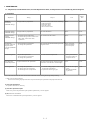
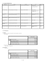
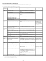
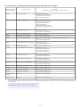
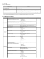
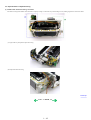
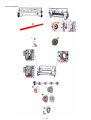
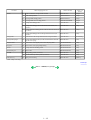
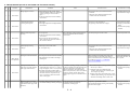
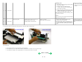
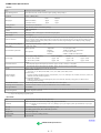
PIXMA iP4000
SERVICE
MANUAL
Canon
Copyright 2004, Canon U.S.A. This technical publication is the proprietary and confidential information of Canon U.S.A. which
shall be retained for reference purposes by Authorized Service Facilities of Canon U.S.A. Its unauthorized use is prohibited.
Scope
This manual has been issued by Canon Inc., to provide the service technicians of this product with the information necessary for qualified persons to learn technical
theory, installation, maintenance, and repair of products. The manual covers information applicable in all regions where the product is sold. For this reason, it may
contain information that is not applicable to your region.
Revision
This manual could include technical inaccuracies or typographical errors due to improvements or changes made to the product. When changes are made to the contents of
the manual, Canon will release technical information when necessary. When substantial changes are made to the contents of the manual, Canon will issue a revised
edition.
The following do not apply if they do not conform to the laws and regulations of the region where the manual or product is used:
Trademarks
Product and brand names appearing in this manual are registered trademarks or trademarks of the respective holders.
Copyright
All rights reserved. No parts of this manual may be reproduced in any form or by any means or translated into another language without the written permission of Canon
Inc., except in the case of internal business use.
Copyright © 2004 by Canon Inc.
CANON INC.
Inkjet SFP Quality Assurance Div.
16-1, Shimonoge 3-chome, Takatsu-ku, Kawasaki, Kanagawa 213-8512, Japan
I. MANUAL OUTLINE
This manual consists of the following three parts to provide information necessary to service the PIXMA iP4000:
Part 1: Maintenance
Information on maintenance and troubleshooting of the PIXMA iP4000
Part 2: Technical Reference
New technology and technical information such as FAQ's (Frequently Asked Questions) of the PIXMA iP4000
Part 3: Appendix
Block diagrams and pin layouts of the PIXMA iP4000
Reference:
This manual does not provide sufficient information for disassembly and reassembly procedures. Refer to the graphics in the separate Parts Catalog.
II. TABLE OF CONTENTS
Part 1: MAINTENANCE
1. MAINTENANCE
1-1. Adjustment, Periodic Maintenance, Periodic Replacement Parts, and Replacement Consumables by Service Engineer
1-2. Customer Maintenance
1-3. Product Life
1-4. Special Tools
1-5. Serial Number Location
2. LIST OF ERROR DISPLAY / INDICATION
2-1. Operator Call Errors
2-2. Service Call Errors
2-3. Warnings
2-4. Troubleshooting by Symptom
3. REPAIR
3-1. Notes on Service Part Replacement (and Disassembling / Reassembling)
3-2. Special Notes on Repair Servicing
3-3. Adjustment / Settings
(1) Paper feed motor adjustment
(2) Gear phase adjustment
(3) Grease application
(4) Waste ink counter setting
(5) User mode
(6) Service mode
Service test print, EEPROM initialization, Waste ink counter reset
Destination settings
3-4. Verification Items
(1) Service test print
(2) EEPROM information print
4. PRINTER TRANSPORTATION
Part 2: TECHNICAL REFERENCE
1. NEW TECHNOLOGIES
2. CLEANING MODE AND AMOUNT OF INK PURGED
3. FAQ (Problems Specific to the iP4000 and Corrective Actions)
Part 3: APPENDIX
1. BLOCK DIAGRAM
2. CONNECTOR LOCATION AND PIN LAYOUT
2-1. Logic Board Ass'y
2-2. Carriage Board (Print Head Connector)
Part 1
MAINTENANCE
1. MAINTENANCE
1-1. Adjustment, Periodic Maintenance, Periodic Replacement Parts, and Replacement Consumables by Service Engineer
(1) Adjustment
Adjustment
Timing
Purpose
Tool
Approx.
time
EEPROM
initialization
(EEPROM settings)
At logic board ass'y replacement
To initialize settings other than the following:
- USB serial number
- Destination setting
- Waste ink counter
- CD-R correction value
None.
1 min.
Destination settings
(EEPROM settings)
At logic board ass'y replacement
To set the destination.
None.
1 min.
Waste ink counter
resetting
(EEPROM settings)
- At bottom case unit replacement
- At ink absorber (QC1-4221 / 4222 / 4223 /
4224 / 4263 / 4264 / 4864 / 4257)
replacement
To reset the waste ink counter.
None.
1 min.
CD-R sensor /
automatic print head
alignment sensor
correction (EEPROM
settings)
- At logic board ass'y replacement
- At carriage unit replacement
To correct the CD-R and automatic print head
alignment sensor.
None. (Correction
performed through
service test print)
2 min.
Print head alignment
- At print head replacement
- At logic board ass'y replacement
- At carriage unit replacement
To ensure accurate dot placement.
- None. (printer buttons)
- Computer (settings via
the printer driver)
2 min.
Paper feed motor
position adjustment*1
At paper feed motor unit replacement
To adjust the belt tension. (Position the paper
feed motor so that the belt is stretched tight.)
None.
2 min.
Grease application
- At carriage unit replacement
- At chassis' upper gear replacement
- At shaft lift (QC1-4331) replacement
- To maintain sliding properties of the carriage,
carriage shaft, and shaft lift.
- To protect the chassis' upper gear.
- FLOIL KG-107A (QY90057)
- MOLYKOTE HP300
(QY9-0035)
1 min.
Note: DO NOT loosen the red screws on both sides of the main chassis, securing the carriage shaft positioning.
*1: Red screws of paper feed motor
The red screws securing the paper feed motor may be loosened only at replacement of the paper feed motor unit.
(2) Periodic maintenance
No periodic maintenance is necessary.
(3) Periodic replacement parts
There are no parts in this printer that require periodic replacement by a service engineer.
(4) Replacement consumables
There are no consumables that require replacement by a service engineer.
1-1
1-2. Customer Maintenance
Adjustment
Timing
Purpose
Tool
Approx. time
Print head alignment
At print head replacement.
To ensure accurate dot placement.
- Printer buttons
- Computer (automatic settings
via the printer driver)
3 min.
Print head cleaning
When print quality is not satisfying.
To improve nozzle conditions.
- Printer buttons
- Computer (settings via the
printer driver)
1 min.
Print head deep
cleaning
When print quality is not satisfying, and not
improved by print head cleaning.
To improve nozzle conditions.
Computer (settings via the
printer driver)
2 min.
Ink tank replacement
When an ink tank becomes empty. (No ink
error)
Paper feed roller
cleaning
When paper does not feed properly.
To clean the paper feed rollers.
Printer buttons
2 min.
CD-R print position
adjustment
At CD-R printing, when necessary
To correct CD-R print position.
Computer (application
software)
5 min.
Bottom plate cleaning
When the back side of the paper is smeared
To clean the platen ribs.
Computer (application
software)
1 min.
-----
-----
1-3. Product Life
(1) Printer
Specified print volume (I) or the years of use (II), whichever comes first.
(I) Print volume
PIXMA iP4000
18,000 pages
Black
1,500 character pattern
7,200 pages
Color
A4, 7.5% duty per color pattern
5,400 pages
A4, photo, borderless printing
300 pages
4 x 6, photo, borderless printing
3,600 pages
Postcard, photo, borderless printing
1,500 pages
(II) Years of use
PIXMA iP4000: 5 years of use
(2) Print head
Print volume:
PIXMA iP4000
18,000 pages
Black
1,500 character pattern
7,200 pages
Color
A4, 7.5% duty per color pattern
5,400 pages
A4, photo, borderless printing
300 pages
4 x 6, photo, borderless printing
3,600 pages
Postcard, photo, borderless printing
1,500 pages
1-2
2 min.
(3) Ink tank (target value)
PIXMA iP4000:
BCI-3eBK: 740 pages (1,500 character pattern, plain paper / standard mode)
1,500 pages (ISO JIS-SCID No. 5 / plain paper / standard mode)
BCI-6C: 550 pages (ISO JIS-SCID No. 5 / plain paper / standard mode)
BCI-6M: 430 pages (ISO JIS-SCID No. 5 / plain paper / standard mode)
BCI-6Y: 360 pages (ISO JIS-SCID No. 5 / plain paper / standard mode)
BCI-6BK: 2,000 pages (ISO JIS-SCID No. 5 / plain paper / standard mode)
1-4. Special Tools
Name
Tool No.
Application
Remarks
MOLYKOTE
HP300
QY9-0035-000
To be applied to the chassis' upper gear, and to the sliding In common with other
portion of the shaft lift.
models.
FLOIL
KG-107A
QY9-0057-000
To be applied to the sliding portion of the carriage, and
the carriage shaft.
In common with other
models.
1-5. Serial Number Location
On the carriage flexible cable holder (visible when the access cover is open).
To the top
<Part 1: 1. MAINTENANCE>
1-3
2. LIST OF ERROR DISPLAY / INDICATION
Errors are indicated by the LED, and warnings are displayed on the monitor of the computer connected to the printer.
2-1. Operator Call Errors (by LED Blinking in Orange)
LED blinking
in orange
2 times
3 times
Error [Error code]
Solution
No paper. (ASF) [1000]
Set the paper in the ASF, and press the Resume/Cancel
button.
No CD-R tray. [1001]*1
Set the CD-R tray, and press the Resume/Cancel button.
No paper in the cassette. [1003]
(No paper in the front paper feed cassette.)
Set the paper in the cassette, and press the Resume/Cancel
button.
Paper jam. [1300]
Remove the jammed paper, and press the Resume/Cancel
button.
Paper jam in the under guide. [1304]
Remarks
Paper jam in the rear guide. [1303]
Front door closed. [1250]
Open the paper output tray.
4 times
No ink. [1601 / 1602 / 1611 / 1612 / 1613]
Replace the empty ink tank(s), or press the Resume/Cancel
button.
5 times
The print head is not installed [1401], or it is not
properly installed (EEPROM data of the print
head is faulty) [1403 / 1405].
Install the print head properly, and close the access cover.
Or, with the print head installed, turn the printer off and on.
6 times
Inner cover open. [1841]*2
Close the inner cover, and press the Resume/Cancel button.
Inner cover open (during printing on paper).
[1846]*2
Close the inner cover, and press the Resume/Cancel button.
CD-R tray guide closed (during CD-R printing).
[1850 / 1855]*1
Open the CD-R tray guide, set the CD-R tray properly, and
press the Resume/Cancel button.
Pressing the
Resume/Cancel button
will exit the error without
ink tank replacement,
however, ink may run out
during printing.
CD-R tray guide open (during printing to paper). Close the CD-R tray guide, and press the Resume/Cancel
button.
[1851 / 1856]*1
7 times*1
No CD-R or DVD-R. [1002]
After setting a CD-R or DVD-R in the tray, set the tray in the
tray guide, and press the Resume/Cancel button.
8 times
Warning: The waste ink absorber becomes
almost full (approx. 95% of the maximum
capacity). [1700]
Pressing the Resume/Cancel button will exit the error, and
enable printing.
In repair servicing, replace the bottom case unit (QM2-1205),
or the ink absorbers (QC1-4222 / 4223 / 4224 / 4263 / 4264 /
4864 / 4221 / 4257).
9 times
The connected digital camera or digital video
After removing the cable between the camera and the printer,
camera does not support Camera Direct Printing. press the Resume/Cancel button, and re-connect the cable.
[2001]
10 times
Automatic duplex printing cannot be performed
(paper size not supported). [1310]
Press the Resume/Cancel button to eject the paper being used
at error occurrence. Printing will resume from on the front
side of the next page.
11 times
Failed in automatic print head alignment. [2500]
Press the Resume/Cancel button, and after confirming the
following, perform print head alignment again:
- Set an appropriate type and size of paper (plain paper, A4 or
letter).
- Check that the nozzle check pattern is properly printed (all
ink ejected, no faint printing).
- Protect the paper output slot from exposure to excessive
light.
Access cover open. [1200]
Close the access cover.
*1: Only for models supporting CD-R printing
*2: Only for models not supporting CD-R printing
1-4
The service call error,
indicating the waste ink
absorber is full, is likely to
occur soon.
Data which was to be
printed on the back side of
paper at error occurrence is
skipped (not printed).
2-2. Service Call Errors (by LED Blinking in Orange and Green Alternately, or Lit in Orange)
LED alternate blinking
in orange and green
Solution
(Replacement of listed parts, which are likely to be faulty)
Error [Error code]
2 times
Carriage error [5100]
- Carriage unit (QM2-1209)
- Timing slit strip film (QC1-4284)
- Logic board ass'y (QM2-1548)*1
- Carriage motor (QK1-0545)
3 times
Paper feed error [6000]
- Timing sensor unit (QM2-1213)
- Timing slit disk film (QC1-4833)
- Feed roller ass'y (QL2-0598)
- Platen unit (QM2-1215)
- Logic board ass'y (QM2-1548)*1
- PAPER FEED MOTOR (QK1-0550)
4 times
Purge unit error [5C00]
- Purge unit (QM2-1210)
- Logic board ass'y (QM2-1548)*1
5 times
ASF (cam) sensor error [5700]
- Sheet feed unit (QM2-1220)
6 times
Internal temperature error [5400]
- Logic board ass'y (QM2-1548)*1
7 times
Waste ink absorber full [5B00]
- Ink absorber (QC1-4222 / 4223 / 4224 / 4263 / 4264 / 4864 / 4221 / 4257)
- Bottom case unit (QM2-1205)*2
8 times
Print head temperature rise error [5200]
- Print head (QY6-0049)
- Logic board ass'y (QM2-1548)*1
9 times
EEPROM error [6800]
- Logic board ass'y (QM2-1548)*1
11 times
Carriage lift mechanism error [5110]
- Lift shaft(QC1-4331)
- Photo interrupter (WG8-5624)
- Sheet feed unit (QM2-1220)
- Logic board ass'y (QM2-1548)*1
12 times
AP position error [6A00]
- Sheet feed unit (QM2-1220)
- Logic board ass'y (QM2-1548)*1
13 times
Paper feed position error [6B00]
- Sheet feed unit (QM2-1220)
- Logic board ass'y (QM2-1548)*1
14 times
Paper feed cam sensor error [6B10]
- Sheet feed unit (QM2-1220)
- Logic board ass'y (QM2-1548)*1
15 times
USB Host VBUS overcurrent [9000]
- Logic board ass'y (QM2-1548)*1
16 times
Valve sensor error [6C00]
- Logic board ass'y (QM2-1548)*1
17 times
Motor driver error [6D00]
- Logic board ass'y (QM2-1548)*1
20 times
Other hardware error [6500]
- Logic board ass'y (QM2-1548)*1
Continuous alternate
blinking
ROM error
- Logic board ass'y (QM2-1548)*1
Lights in orange
RAM error
- Logic board ass'y (QM2-1548)*1
*1: Before replacement of the logic board ass'y, check the waste ink amount (by service test print or EEPROM information print). If the waste ink amount is 7% or
more, also replace the bottom case unit (QM2-1205) or the ink absorbers (QC1-4222 / 4223 / 4224 / 4263 / 4264 / 4864 / 4221 / 4257) when replacing the
logic board ass'y.
[See Section 3-3. Adjustment / Settings, (6) Service mode, for details.]
*2: Reset the waste ink counter when replacing the bottom case unit.
[See Section 3-3. Adjustment / Settings, (6) Service mode, for details.]
1-5
2-3. Warnings
Printer (no LED indications):
Displayed warning
Remarks
Low ink of 3eBK, 6C, 6M, 6Y, or 6BK (at detection
of no remaining raw ink)
Status indication only.
Print head temperature rise
If the print head temperature is high when the access cover is opened, the warning is displayed*1.
When the print head temperature falls, the warning is released.
Protection of excess rise of the print head temperature If the print head temperature exceeds the specified limit, a Wait is inserted during printing,
*1: If the warning is displayed, the carriage does not move to the ink tank replacement position when the access cover is opened.
2-4. Troubleshooting by Symptom
Symptom
The power does not turn on.
The power turns off immediately after power-on.
Solution
Replace the
- AC adapter, or
- logic board ass'y*1.
The print head is not recognized.
Faulty operation The print head does not move to the home position.
Remove and re-install the print head, or replace the
- print head, or
- logic board ass'y*1.
A strange noise occurs.
Remove foreign material, or attach a removed part if any.
Printing stops mid-way.
Replace the logic board ass'y*1.
Multiple sheets feed.
Replace the
- sheet feed unit,
- cassette.
Paper does not feed.
Remove foreign material, or replace the
- sheet feed unit, or
- cassette.
Paper feeds at an angle.
Remove foreign material, or replace the
- sheet feed unit, or
- cassette.
No printing, or no color ejected.
Replace the
- ink tank,
Paper feed
problems
- print head*2,
- logic board ass'y*1, or
- purge unit.
Printing is faint, or white lines appear on printouts
even after print head cleaning.
Line(s) not included in the print data appears on
printouts.
Remove and re-install the print head, or replace the
- ink tank,
- print head*2,
- purge unit, or
- logic board ass'y*1.
Unsatisfactory
print quality
Paper gets smeared.
Feed several sheets of paper,
perform bottom plate cleaning, or
clean the paper path with cotton swab or cloth.
A part of a line is missing on printouts.
Replace the
- ink tank, or
- print head*2.
Color hue is incorrect.
Replace the
- ink tank, or
- print head*2, or
perform print head alignment.
1-6
Remarks
Printing is incorrect.
Replace the logic board ass'y*1.
No ejection of black ink.
Replace the
- ink tank, or
- print head*2.
Graphic or text is enlarged on printouts.
When enlarged in the carriage movement direction, clean grease
or oil off the timing slit strip film, or replace the
- timing slit strip film,
- carriage unit, or
- logic board ass'y*1.
When enlarged in the paper feed direction, clean grease or oil off
the timing slit disk film, or replace the
- timing slit disk film,
- timing sensor unit, or
- logic board ass'y*1.
*1: Before replacement of the logic board ass'y, check the waste ink amount (by service test print or EEPROM information print). If the waste ink amount is 7% or
more, also replace the bottom case unit (QM2-1205) or the ink absorbers (QC1-4222 / 4223 / 4224 / 4263 / 4264 / 4864 / 4221 / 4257) when replacing the
logic board ass'y.
[See Section 3-3. Adjustment / Settings, (6) Service mode, for details.]
*2: Replace the print head only after the print head deep cleaning is performed 2 times, and when the problem persists.
To the top
<Part 1: 2. LIST OF ERROR DISPLAY / INDICATION>
1-7
3. REPAIR
3-1. Notes on Service Part Replacement (and Disassembling / Reassembling)
Service part
Logic board ass'y
QM2-1548
Bottom case unit
QM2-1205
Notes on replacement*1
Adjustment / settings
- Before removal of the logic board ass'y,
remove the power cord, and allow for
approx. 1 minute (for discharge of
capacitor's accumulated charges), to
prevent damages to the logic board
ass'y.
- Before replacement, check the waste
ink amount (by service test print or
EEPROM information print). If the
waste ink amount is 7% or more, also
replace the bottom case unit or the ink
absorbers when replacing the logic
board ass'y. See 3.3. Adjustment /
Settings, (6) Service mode, for details.
[See 3-3. Adjustment / Settings, (6)
Service mode, for details.]
After replacement:
1. Initialize the EEPROM.
2. Reset the waste ink counter.
3. Set the destination in the EEPROM.
4. Correct the CD-R and automatic print
head alignment sensors.
[See 3-3. Adjustment / Settings, (6)
Service mode, for details of 1 to 4]
5. Perform the print head alignment in
the user mode.
- EEPROM information print
- Service test print
- Printing via parallel or USB
connection
After replacement:
1. Reset the waste ink counter.
[See 3.3. Adjustment / Settings, (6)
Service mode.]
- Service test print
At replacement:
1. Apply grease to the sliding portions.
[See 3-3. Adjustment / Settings, (3)
Grease application.]
- Service test print (Confirm CD-R
and automatic print head alignment
sensor correction.)
Operation check
- Direct printing from a digital camera
Ink absorber
QC1-4222 / 4223 / 4224 /
4263 / 4264 / 4864 / 4221 /
4257
Carriage unit
QM2-1209
After replacement:
1. Correct the CD-R and automatic print
head alignment sensors.
[See 3.3. Adjustment / Settings, (6)
Service mode.]
2. Perform the print head alignment in
the user mode.
Paper feed motor unit
QK1-0550
- The red screws securing the paper feed At replacement:
motor are allowed to be loosened. (DO 1. Adjust the paper feed motor.
NOT loosen any other red screws.)
[See 3-3. Adjustment / Settings, (1)
Paper feed motor adjustment.]
1-8
Service part
Notes on replacement*1
Shaft lift
QC1-4331
Timing slit strip film
QC1-4284
Timing slit disk film
QC1-4833
Adjustment / settings
Operation check
At replacement:
1. Apply grease to the sliding portions.
[See 3.3. Adjustment / Settings, (3)
Grease application.]
- Service test print
- Upon contact with the film, wipe the
After replacement:
film with ethanol.
1. Perform the print head alignment in
the user mode.
- Confirm no grease is on the film. (Wipe
off any grease thoroughly with
ethanol.)
- Do not bend the film
- Service test print
After replacement:
1. Perform the print head alignment in
the user mode.
- Service test print
Print head
QY6-0049
*1: General notes:
- Make sure that the flexible cables and wires in the harness are in the proper position and connected correctly.
[See 3-2. Special Notes on Repair Servicing, (1) Flexible cable and harness wiring, connection, for details.]
- Do not drop the ferrite core, which may cause damage.
- Protect electrical parts from damage due to static electricity.
- Before removing a unit, after removing the power cord, allow the printer to sit for approx. 1 minute (for capacitor discharging to protect the logic board
ass'y from damages).
- Do not touch the timing slit strip film and timing slit disk film. No grease or abrasion is allowed.
- Protect the units from soiled with ink.
- Protect the housing from scratches.
- Exercise caution with the red screws, as follows:
i. The red screws of the paper feed motor may be loosened only at replacement of the paper feed motor unit (DO NOT loosen them in other cases).
ii. DO NOT loosen the red screws on both sides of the main chassis, securing the carriage shaft positioning (they are not adjustable in servicing).
To the top
<Part 1: 3. REPAIR, 3-1>
1-9
3-2. Special Notes on Repair Servicing
(1) Flexible cable and harness wiring, connection
Be careful of wiring of the flexible cables and harness. Improper wiring or connection may cause breakage of a line, leading to ignition or emission of smoke.
(I) Logic board ass'y and operation panel unit wiring
(II) Paper feed motor side wiring
To the top
<Part 1: 3. REPAIR, 3-2>
1 - 10
3-3. Adjustment / Settings
(1) Paper feed motor adjustment
Perform the following adjustments when the paper feed motor unit is replaced:
1) When attaching the motor, fasten the screws so that the belt is properly stretched (in the direction indicated by the blue arrow in the figure below).
2) After replacement, be sure to perform the service test print, and confirm that no strange noise or faulty print operation (due to dislocation of the belt or gear, or
out-of-phase motor, etc.) occurs.
Note: The red screws securing the paper feed motor may be loosened only at replacement of the paper feed motor unit. DO NOT loosen them in other cases.
(2) Gear phase adjustment
In attaching the lift transmission gear (QC1-4327), adjust the phase so that the protrusion of the lift transmission gear (QC1-4327) fits into the recess of the
carriage shaft cam R (QC1-4382), as shown in the figure below.
1 - 11
(3) Grease application
1 - 12
Part name
Where to apply grease / oil
Grease / oil name
Grease / oil
amount
1
Entire surface the carriage slider contacts
FLOIL KG107A
3 drops
2
Cam contact portion
FLOIL KG107A
1 drop
3
Carriage shaft sliding portion
FLOIL KG107A
1 drop
4
Carriage shaft cam L sliding portion
MOLYKOTE HP300
2 drops
5
Carriage shaft sliding portion
FLOIL KG107A
1 drop
6
Carriage shaft sliding portion on the left side of the chassis (at 2
locations)
FLOIL KG107A
1 drop
7
Carriage shaft cam L sliding portion on the left side of the chassis (at
2 locations)
FLOIL KG107A
2 drops
8
Carriage shaft sliding portion on the right side of the chassis (at 2
locations)
FLOIL KG107A
1 drop
Carriage shaft
9
Entire surface of the carriage shaft where the carriage unit slides
FLOIL KG107A
200 to 400mg
Carriage shaft spring L
10
Carriage shaft sliding portion (over the area more than 2/3 from the
top end of the spring)
FLOIL KG107A
1 drop
Lift gear 2 shaft
11
Outer surface of the stepped portion where the spring slides
MOLYKOTE HP300
1 drop
Lift gear 2
12
Outer surface of the spring sliding bushing
MOLYKOTE HP300
1 drop
Chassis
13
Carriage shaft cam R sliding portion
MOLYKOTE HP300
1 drop
Transmission gear
14
Inner surface
MOLYKOTE HP300
1 drop
Lift shaft
15
Spring sliding portion (4 locations)
FLOIL KG107A
1 drop
16
Pressure roller ass'y contact portion (4 locations)
FLOIL KG107A
1 drop
17
Spring contact bushing
FLOIL KG107A
Half drop
Chassis
Feed roller ass'y
Note: 1 drop = 9 to 18 mg
To the top
<Part 1: 3. REPAIR, 3-3 (1) to (3)>
1 - 13
(4) Waste ink counter setting
When the logic board ass'y is replaced, reset the waste ink counter. In addition, according to the waste ink amount, replace the waste ink absorber (the bottom case
unit or the ink absorbers). The standard amount for waste ink absorber replacement is given in the table below.
Waste ink amount*1
Bottom case unit or ink absorber replacement
Less than 7%
Not required.
7% or more
Required.
*1: Check the waste ink amount by service test print or EEPROM information print.
[See 3.3. Adjustment / Settings, (6) Service mode, for details.]
(5) User mode
Function
Procedures
Remarks
Print head manual cleaning
- Cleaning both black and color:
See "Standalone printer operation" below.
- Cleaning black or color separately, or both black and color:
Perform from the printer driver's Maintenance tab.
Print head deep cleaning
- Cleaning black or color separately, or both black and color:
Perform from the printer driver's Maintenance tab.
Paper feed roller cleaning
See "Standalone printer operation" below.
Nozzle check pattern printing
See "Standalone printer operation" below.
Also available from the printer driver's
Maintenance tab.
Print head alignment
See "Standalone printer operation" below.
In Custom Settings of the printer driver's
Maintenance tab, manual print head alignment (by
selecting the optimum values) as with the
conventional models can be performed.
Bottom plate cleaning
Perform from the printer driver's Maintenance tab.
Cleaning of the platen ribs when the back
side of paper gets smeared.
Print head replacement
The print head is replaceable at the same position as for
ink tank replacement. (Open the access cover. When the
carriage stops at the center, the print head can be
replaced.)
<Standalone printer operation>
1) Turn on the printer.
2) Press and hold the Resume/Cancel button until the LED blinks the specified number of times listed in the table below, and release it. The operation starts.
LED blinking
Operation
Remarks
1 time
Print head manual cleaning
2 times
Nozzle check pattern printing
3 times
Paper feed roller cleaning
4 times
Automatic print head alignment
Set a sheet of plain paper (A4 or letter) in the ASF.
5 times
Bottom plate cleaning
Fold a sheet of plain paper (A4 or letter) in half crosswise, then unfold and set
it in the ASF with the folded ridge facing down.
6 times or more
Unspecified
Set a sheet of plain paper (A4 or letter) in the ASF or the cassette (according
to the Paper Feed switch setting).
1 - 14
(6) Service mode
Function
Procedures
Remarks
Service test print
- Model name
- ROM version
- USB serial number
- Waste ink amount
- CD-R sensor correction
See "Service mode operation procedures" below.
Set a sheet of A4- , letter-, or larger-sized paper.
For print sample, see 3-4. Verification Items, (1) Service
test print, <Service test print sample>.
EEPROM initialization
See "Service mode operation procedures" below.
The following items are NOT initialized:
- USB serial number
- Destination settings
- Waste ink counter
- CD-R correction value
Waste ink counter reset
See "Service mode operation procedures" below.
If the waste ink amount is 7% or more, replace the bottom
case unit, or the ink absorbers.
Destination settings
See "Service mode operation procedures" below.
Other than Japan: iP4000
Japan: iP4100
Note: At the end of the service mode, press the Power button. To protect the media sensor from being dislocated during transportation, the paper lifting plate of
the sheet feeder unit will be raised.
<Service mode operation procedures>
1) With the printer power turned off, while pressing the Resume/Cancel button, press and hold the Power button. (DO NOT release the buttons. The LED lights in
green to indicate that a function is selectable.)
2) While holding the Power button, release the Resume/Cancel button. (DO NOT release the Power button.)
3) While holding the Power button, press the Resume/Cancel button 2 times, and then release both the Power and Resume/Cancel buttons. (Each time the
Resume/Cancel button is pressed, the LED lights alternately in orange and green, starting with orange.)
4) When the LED lights in green, press the Resume/Cancel button the specified number of time(s) according to the function listed in the table below. (Each time
the Resume/Cancel button is pressed, the LED lights alternately in orange and green, starting with orange.)
Time(s)
LED
0 times
Green
Power off
When the print head is not installed, the carriage returns and locks
in the home position.
1 time
Orange
Service test print
See 3-4. Verification Items, (1) Service test print.
2 times
Green
EEPROM information print
See 3-4. Verification Items, (2) EEPROM information print.
3 times
Orange
EEPROM initialization
4 times
Green
Waste ink counter resetting
5 times
Orange
Destination settings
6 times
Green
Print head deep cleaning
7 times
Green
CD-R test print
Not used in servicing.
8 times
Orange
CD-R print position correction
(horizontal)
Not used in servicing.
9 times
Green
CD-R print position correction
(vertical)
Not used in servicing.
10 times or more
Function
Remarks
Proceed to the step 5), and follow the Destination settings
procedures.
Return to the menu selection
5) After the function (menu) is selected, press the Power button. The LED lights in green, and the selected function is performed. (When the operation completes,
the printer returns to the menu selection mode automatically.)
1 - 15
<Destination settings procedures>
In the destination settings mode, press the Resume/Cancel button the specified number of time(s) according to the destination listed in the table below, and press
the Power button.
Time(s)
LED
Destination
1 time
Orange
Japan: iP4100
2 times
Green
Other than Japan, non-support of CD-R printing (A4): iP4000
3 times
Orange
Other than Japan, non-support of CD-R printing (LTR): iP4000 (LTR)
4 times
Green
Other than Japan, support of CD-R printing (A4): iP4000
5 times
Orange
Other than Japan, support of CD-R printing (LTR): iP4000 (LTR)
6 times or
more
Return to the menu selection
Note: After setting the destination, confirm the model name in service test print or EEPROM information print.
[See 3.4. Verification Items, (1) Service test print, or (2) EEPROM information print.]
To the top
<Part 1: 3. REPAIR, 3-3 (4) to (7)>
1 - 16
3-4. Verification Items
(1) Service test print
<EEPROM information contents>
On the service test print (sample below), confirm the EEPROM information as shown below. (The information is given in the upper portion of the printout.)
<Print check items>
On the service test print (sample below), confirm the following items:
- Check 1, nozzle check pattern: Ink shall be ejected from all nozzles
- Check 2, top of form accuracy: The line shall not extend off the paper.
- Check 3, vertical straight lines: The line shall not be broken.
- Check 4, halftone: There shall be no remarkable streaks or unevenness.
- Check 5, CD-R / automatic print head alignment sensor correction: The results shall be OK.
1 - 17
<Service test print sample>
(2) EEPROM information print
<How to read EEPROM information print>
Print sample:
iPXXXX V1.02 IF(USB1=1 1284=0) D=004.5 ST=2004/05/27-18:30
ER(ER0=1000 ER1=5100 LPT=2004/06/03-09:09
PC(M=002 R=000 T=001 D=009 C=009)
CLT(BK=2004/06/19-18:30 CL=2004/06/19-18:30)
CH=00002 CT(BK1=040 BK2=020 C=109 M=012 Y=113) IS(BK1=1 BK2=0 C=1 M=1 Y=1)
P_ON(S=00009) A_REG=1 M_REG=0
UR(A(BKoe)=+01 B(Coe)=-01 C(Moe)=+01 D(SCoe)=-01 E(SMoe)=+01 F(PBKoe)=+01
G(BKbi)=+01 H(CLbi)=+01 I(BK-CL)=+01 J(SCLbi)=+01 K(C-SC)=+01 L(M-SM)=+01)
WP=0024 CDIN(LG=001 PB=000) MSD(015)
PAGE(All=00083 PP=00035 HR+MP=00003 PR+SP+SG =00000 GP =00000 PC=00000 EV=00000)
UCPAGE(All=00083 PP=00035 HR+MP=00003 PR+SP+SG =00000 GP =00000 PC=00000 EV=00000)
BPPAGE(All=00083 BSGP=00003 PC=00000)
1 - 18
CDPAGE(All=000) EDGE=00083 L=00000 CDR=00000
CDRP=(-00005,-00029) CDRS=(000)
Head TempBK=18.5 Head TempC=17.5 Env Temp=30.0 FF(3F 3F 3F)
HDEEPROM
V0001
SN=0318-A43D
LN(00000 00000 00001 00003 00001 00000 00000)
ID=00
IL=(BK=000 C=000 M=000 Y=000 C2=000 M2=000 PBK=000)
Printed items:
1. Model name 2. ROM version 3. Connected I/F (USB1/1284) 4. Waste ink amount 5. Installation date
6. Operator call/service call error record 7. Last printing time
8. Purging count (manual/deep cleaning/timer/dot count/ink tank or print head replacement)
9. Cleaning time (BK/CL)
10. Print head replacement count 11. Ink tank replacement count (pigment BK/dye BK/C/M/Y) 12. Ink status (pigment BK/dye BK/C/M/Y)
13. Power-on count (soft) 14. Automatic print head alignment by user 14-1. Manual print head alignment by user
15. User print head alignment values (Bkoe/Coe/Moe/SCoe/SMoe/PBKoe/BKbi/CLbi/BK-PCBK/SCLbi/C-SC/M-SM)
16. Wiping count 17. Camera Direct Print-supported device connection record 18. Longest period where printing stops
19. ASF feed pages (total, plain paper, High Resolution Paper & Matte Photo Paper, Photo Paper Pro & Photo Paper Plus Glossy & Photo Paper Plus Semi-gloss,
Glossy Photo Paper, Postcard, Envelope)
20. U-turn cassette feed pages (total, plain paper, High Resolution Paper & Matte Photo Paper, Photo Paper Pro & Photo Paper Plus Glossy & Photo Paper Plus
Semi-gloss, Glossy Photo Paper, postcard, envelope)
21. Auto duplex print pages (total, Photo Paper Plus Double Sided, postcard)
22. Camera Direct print pages (total) 23. Borderless print pages 24. L & 4x6 print pages
25. Number of CD-Rs printed
26. CD-R print position adjustment 27. CD-R sensor correction value
28. Print head temperature (BK/CL) 29. Inside temperature 30. Line inspection information
HDEEPROM
31. Version
32. Serial number
33. Lot number
34. Print head ID
35. Ink ejection level (BK/C/M/Y/C2/M2/PBK)
To the top
<Part 1: 3. REPAIR, 3-4>
1 - 19
4. PRINTER TRANSPORTATION
This section describes the procedures for transporting the printer for returning after repair, etc.
1) In the service mode, press the Power button to finish the mode, and confirm that the paper lifting plate of the sheet feeder unit is raised.
2) Keep the print head and ink tanks installed in the carriage.
[See Caution 1 below.]
3) Turn off the printer to securely lock the carriage in the home position. (When the printer is turned off, the carriage is automatically locked in place.)
[See Caution 2 below.]
4) To further secure the carriage to prevent movement from the home position during transportation, make and use a fixing tool in the following procedures:
i. Fold an A4-sized paper 5 times, and wrap it twice with tape, as shown in Figure A below (to prevent the fixing tool from caught into the inside of the
printer).
ii. Insert the fixing tool between the carriage and the main case unit, and securely fix it with tape, as shown in Figures B and C below.
Note: The tape should be similar to the polyester tape used at shipment, which will not easily be torn or removed, or leave adhesive on the unit when
removed.
Leave a sufficient length of tape to fix the tool so that the tape end is easily seen even when the access cover is closed, so that the user will
remove the tool from the returned printer without fail.
Figure A:
Figure B:
Figure C:
Caution:
(1) If the print head is removed from the printer and left alone by itself, ink (especially the pigment black ink) is likely to dry. For this reason, keep the print
head installed in the printer even during transportation.
(2) Securely lock the carriage in the home position, to prevent the carriage from moving and applying stress to the carriage flexible cable, or causing ink
leakage, during transportation.
Memo:
If the print head must be removed from the printer and transported alone, perform the following:
(1) Install both the black and color ink tanks (to prevent the nozzles from drying).
(2) Attach the protective cap (used when the packing was opened) to the print head (to protect the print head face from damage due to shocks).
To the top
<Part 1: 4. PRINTER TRANSPORTATION>
1 - 20
Part 2
TECHNICAL REFERENCE
1. NEW TECHNOLOGIES
(1) Multi-paper handling
Paper feeding through the auto sheet feeder and the front cassette, automatic duplex printing, and CD-R / DVD-R direct printing is available as a standard feature.
- Auto sheet feeder: Supports credit card size and sticker sheets as well as conventional paper types and sizes.
- Front cassette: Except credit card size and sticker sheets, supports the same types and sizes of paper as the auto sheet feeder.
- Automatic duplex printing unit built-in: By using Photo Paper Plus Double Sided, a photo album can be created automatically.
- CD-R / DVD-R direct printing unit built-in: By incorporating CD-R / DVD-R tray feeder functionality into the printer, CD-R / DVD-R direct printing can
be performed without using a CD-R tray feeder.
Front loading and operation without any lever settings offers easy and quick printing.
(2) New design
- Complete renovation to a new generation printer design
- Elegant-looking housing with mirror finished surface
- Various features and functionality in a compact body comparative to the i850 in size.
(3) Automatic duplex printing unit installed as a standard feature
For the following paper types and sizes, automatic duplex printing can be performed:
- Type: Plain paper, Super White Paper (double-sided plain paper), Photo Paper Plus Double Sided (double-sided glossy photo paper)
- Size: A5, B5, 5" x 7", A4, LTR
To the top
<Part 2: 1. NEW TECHNOLOGIES>
2-1
2. CLEANING MODE AND AMOUNT OF INK PURGED
To prevent printing problems due to bubbles, dust, or ink clogging, print head cleaning is performed before the start of printing, except in the following cases:
- Cleaning on arrival: Performed when the access cover is closed.
- Cleaning by dot count: Performed after ejection of paper (or after printing on the back side of paper when auto duplex printing is performed).
- Manual cleaning / deep cleaning: Performed manually.
<Cleaning mode list>
Black: Pigment-based black
Color: Dye-based black, cyan, magenta, yellow
Condition
On arrival of the printer
Details
Amount of ink used (g)
First and second cleaning after shipped from the plant.
(Black/Color)
Timer cleaning - 0*2
(Black only)
Timer cleaning - 1
(Black only)
Timer cleaning - 2
(Black only)
Timer cleaning - 3*3
(Black/Color)
Timer cleaning - 4
(All in sequence)
Timer cleaning - 5
(All in sequence)
Timer cleaning - 6
(All in sequence)
Timer cleaning - 7
(All in sequence)
Timer cleaning - 8
(All in sequence)
Timer cleaning - 9
(All in sequence)
Timer cleaning - 10
Est. required time (sec.)
70
1.50 (Color)
(All in sequence)
Dot count cleaning*1
0.45 (Black)
0.14 (Black)
When the specified number of dots are printed since the
previous Black/Color cleaning. (Cyan and magenta dots are 0.50 (Color)
counted by large and small nozzles separately.)
30 (Black)
If 24 to 60 hours have elapsed since the previous Black
cleaning till the start of the next printing.
0.14 (Black)
30 (Black)
If 120 to 336 hours have elapsed since the previous
Black/Color cleaning till the start of the next printing.
0.14 (Black)
30 (Black)
0.50 (Color)
35 (Color)
If 336 to 504 hours have elapsed since the previous
Black/Color cleaning till the start of the next printing.
0.45 (Black)
60
35 (Color)
If 60 to 96 hours have elapsed since the previous Black
cleaning till the start of the next printing.
If 96 to 120 hours have elapsed since the previous Black
cleaning till the start of the next printing.
1.00 (Color)
If 504 to 720 hours have elapsed since the previous
Black/Color cleaning till the start of the next printing.
60
If 720 to 1,080 hours have elapsed since the previous
Black/Color cleaning till the start of the next printing.
60
If 1,080 to 2,160 hours have elapsed since the previous
Black/Color cleaning till the start of the next printing.
0.78 (Black)
If 2,160 to 4,320 hours have elapsed since the previous
Black/Color cleaning till the start of the next printing.
1.58 (Black)
If 4,320 to 8,640 hours have elapsed since the previous
Black/Color cleaning till the start of the next printing.
1.58 (Black)
(All in sequence)
If 8,640 or longer hours have elapsed since the previous
Black/Color cleaning till the start of the next printing.
At print head replacement
When the print head is removed and installed.
60
1.00 (Color)
65
1.00 (Color)
65
1.00 (Color)
65
0.45 (Black)
70
(All in sequence)
1.50 (Color)
At ink tank replacement
0.30 (Black)
45 (All in sequence)
(Black/Color)
1.00 (Color)
30 (Black)
35 (Color)
2-2
- Via the operation panel (All at the same time only)
0.14 (Black)
45 (All at the same time)
(Black/Color/All at the same
time)
- Via the printer driver (Selectable from Black, Color, or
All at the same time)
0.50 (Color)
30 (Black)
Deep cleaning
Via the printer driver (Selectable from Black, Color, or All
at the same time)
1.58 (Black)
65 (All at the same time)
1.00 (Color)
45 (Black)
Manual cleaning
(Black/Color/All at the same
time)
40 (Color)
50 (Color)
If the print head has not been
capped before power-on
(All in sequence)
0.30 (Black)
45 (All in sequence)
1.00 (Color)
*1: The dots since the previous cleaning are counted by Black and Color separately. For this reason, the cleaning mode may differ according to Black or
Color.
*2: When 24 to 60 hours have elapsed since the previous Black cleaning, timer cleaning - 0 is performed. However, this cleaning will be conducted up
to 5 times from the printer installation, and no further timer cleaning - 0 will be performed.
*3: The period of time since the previous cleaning is counted by Black and Color separately. For this reason, the cleaning mode may differ according to
Black or Color.
To the top
<Part 2: 2. CLEANING MODE AND AMOUNT OF INK PURGED>
2-3
3. FAQ (Problems Specific to the iP4000 and Corrective Actions)
No.
*
Function
Phenomenon
Margin (approx. 0.3mm)
1
C
Print results
Condition
Cause
- Paper feeding from the cassette, Photo
Paper Plus Double Sided (A4), borderless
printing, printing on the back side of
paper
Corrective action
- In the printer driver, increase the amount of
extension.
Possible call or complaint
- A margin appears on printouts.
- Paper feeds at an angle.
- Change the paper feeding method from the
cassette to the auto sheet feeder.
- In the low temperature and low humidity
environment
2
B
- Skewed paper feeding
- Plain paper
- If paper is curled, straighten it.
- Paper feeds at an angle.
- Printing on the platen
- In the high temperature and high humidity
environment
- Try printing on the other side of paper.
- Printing is performed on the
platen.
Print results
- The back side of paper gets
smeared.
Variation in the top of form
accuracy
3
4
B
B
C
- Skewed paper feeding
- Photo Paper Plus Double Sided
A
Due to decrease of paper feed capability in
the low temperature and low humidity
environment
- Margin
- 2L size (Japan only)
- With the print head and ink tanks installed
- The phenomenon occurred in the freight
handling test.
Safety during
transportation
Print results
- Set the top margin to 4mm or more.
- Print start position varies.
- In the printer driver, increase the amount of
extension.
- A margin appears on printouts.
- Paper feeds at an angle.
- Change the paper feeding method from the
cassette to the auto sheet feeder.
Print results
Soiling on the back side of
paper (lines or streaks parallel
to the paper feed direction)
6
- In the low temperature and low humidity
environment
- Not solved even when the number of
sheets stacked in the auto sheet feeder or
the cassette is reduced
Print results
Carriage lock lever dislocation
5
- A5 or legal size
- After continuous borderless printing of
small sized paper (such as 4 x 6), when a
larger sized paper (such as A4) is printed.
- With Photo Paper Plus Double Sided or
postcards, the phenomenon is likely to be
noticeable and to be complained of by
users, as printing is performed on both
sides of such paper.
In borderless printing, printing is performed
to the size slightly larger than the paper size,
and ink off the paper is absorbed by the
platen's ink absorber. Absorbed ink may
attach to the platen rib(s) after several dozen
sheets are printed, causing soiling at the
leading edge of paper or on the back side of
paper.
Soiling on paper in automatic
- Automatic duplex printing (Photo Paper
On the rib(s) inside the sheet feed unit used
duplex printing (lines or streaks
Plus Double Sided, postcards, plain paper) for duplex printing, ink mist may
perpendicular to the paper feed
accumulate, smearing paper.
direction)
2-4
When returning the repaired printer to the user,
insert the fixing tool (A4 plain paper folded 5
times) between the main case and the carriage, and
fix it with tape. [See Part 1, 4. PRINTER
TRANSPORTATION]
During transportation for return
after repair, Ink dries, and no
ink is ejected.
1. Perform Bottom plate cleaning (from the printer
driver) up to 3 times*1.
- Paper gets smeared.
*1:
Change the paper in each Bottom plate
cleaning. The cleaning can end when paper
does not get any soiling.
- The back side of paper gets
smeared.
2. If soiling on the paper still remains after 3 times
of Bottom plate cleaning, wipe the platen rib(s)
and their surroundings with a cotton swab.
Temporary operational solution:
- Paper gets smeared.
Cancel automatic duplex printing, and manually
print each side of paper.
- The back side of paper gets
smeared.
Cleaning by user:
1. Perform Bottom plate cleaning (from the printer
driver) up to 3 times*1.
*1:
7
B
cleaning was performed, and the
platen ribs were cleaned with
cotton swab, paper gets
smeared.
Change the paper in each Bottom plate
cleaning. The cleaning can end when paper
does not get any soiling.
2. If soiling on the paper still remains after 3 times
of Bottom plate cleaning, wipe the platen rib(s)
and their surroundings with a cotton swab.
Print results
If the phenomenon persists after conducting 1 and
2, servicing is required.
Service:
Wipe any soiling or dirt off from the sheet feed unit
and the bottom case unit ribs*2.
Scratches on paper
8
C
Print results
- PP-101D, PP-101, PR-101, SG-101, etc.
- Paper is scratched.
- Paper feeding from the cassette
- Marks appear on printed paper.
- Multiple number of sheets loaded
- Change the paper feeding method from the
cassette to the auto sheet feeder.
- If automatic duplex printing is performed, cancel
it, and, by setting only a single sheet of paper in
the auto sheet feeder, manually print each side of
paper.
Scratches on the PF return lever
due to paper feeding from the
cassette, and duplex printing
path.
*2: Locations to clean in servicing when soiling on paper in automatic duplex printing persists:
* Occurrence level:
A: The symptom is likely to occur frequently. (Caution required)
B: The symptom may occur under certain conditions, but likeliness is assumed very low in practical usage.
C: The symptom is unlikely to be recognized by the user, and no practical issues are assumed.
To the top
<Part 2: 3. FAQ>
2-5
Part 3
APPENDIX
PIXMA iP4000 Specifications
<Printer>
Type
Desktop serial color bubble jet printer
Paper feeding method
Auto sheet feed (ASF, cassette, automatic duplex printing, CD-R printing*1)
Resolution
4,800 x 1,200dpi (Max.)
Throughput
Black (Fine Black)
Color (Fine Color)
Printing direction
Bi-directional, uni-directional
Print width
Max. 203.2mm (216mm in borderless printing)
Interface
USB 2.0 Full Speed
IEEE1284
ASF stacking capacity
Plain paper: Max. 13mm (Approx. 150 sheets of 65g/m2 paper)
Paper weight
64 to 105g/m2
Detection functions
Cover open, Presence of print head, Remaining ink amount (optical / dot count), Printing position, Paper presence, Paper end
sensor, Waste ink amount, Internal temperature, Pick-up roller, Paper feed roller position, Carriage position, Head-to-paper
distance, Supported camera direct printing device, Presence of CD-R, Supported paper size for duplex printing, Opennig /
Closing of paper output tray
Noise during printing (Highest
print quality)
- Highest print quality settings: Approx. 35dB
- Quiet mode: TBD
Draft
25ppm
17ppm
During operation
Environmental requirements
Standard
15ppm
11ppm
Temperature
Humidity
Temperature
Humidity
Non operation
Power consumption
Approx. 16W
Approx. 16W
5C to 35C (41F to 95F)
10%RH to 90%RH (no condensation)
0C to 40C (32F to 104F)
5%RH to 95%RH (no condensation)
Power supply
Power supply voltage, frequency
AC 100 to 120V, 50/60Hz
AC 220 to 240V, 50/60Hz
Standby
Approx. 0.5W
Approx. 0.5W
Power-off
Approx. 0.25W
Approx. 0.25W
External dimensions
Printer:
With the paper support and output tray retracted: Approx. 418 (W) x 286 (D) x 170 (H)mm
With the paper support and output tray extended: Approx. 418 (W) x 555 (D) x 325 (H)mm
Weight
Approx. 6.7kg, not including print head and optional units
Related standards
(Printer, Adapter)
Electromagnetic radiance:
VCCI, FCC, IC, CE Mark, Taiwan EMC, C-tick, CCC (EMC), Korea MIC, Gost-R
Electrical safety:
Electrical Appliance and Material Safety Law (DENAN), UL, C-UL, CB Report, GS, CE Mark, Gost-R, FT, SASO, CCC,
SPRING, Korea EK, IRAM (Argentine)
Environmental regulations:
RoHS (EU), WEEE (EU), Korea Package Recycle Law, Green Point (Germany), Energy Star, Eco Mark, Law on
Promoting Green Purchasing
Serial number location
On the carriage flexible cable holder (visible when the access cover is open.)
Remaining ink amount detection
Available (automatic detection by optical method and dot count, enabled at default)
Paper type detection
Not available
Print head alignment
Available (automatic or manual alignment via driver utilities, or the Resume/Cancel button in Camera Direct Printing,
automatic alignment at default)
*1: Only for CD-R printing supported regions
<Print head>
Type
Single head with 5 removable ink tanks (each color)
Print head
Black: 320 nozzles in 2 vertical lines (600dpi), 30pl (pigment-based black)
Color: 256 nozzles in 2 vertical lines per color x 6 (1,200dpi), 5.5pl (cyan, magenta, yellow, dye-based black) / 2.5pl (cyan,
magenta)
Ink color
Pigment-based black, Dye-based black, cyan, magenta, yellow
Ink tank
BCI-3eBK (pigment-based), BCI-6C/M/Y/BK (dye-based)
Weight (Net)
Print head, approx. 60g
Supply method
As a service part (not including ink tanks)
Part number
QY6-0049-000
To the top
<PIXMA iP4000 Specifications>
3-7