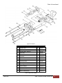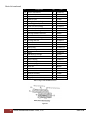
1
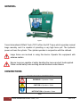
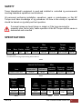
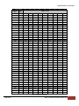
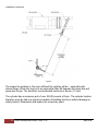
TECHNICAL MANUAL EZ Torque Operation Manual © 2005-2015 Texas International Oilfield Tools, LTD. Published by Texas International Oilfield Tools, LTD, Engineering 14620 Henry Road. • Houston, TX 77060 www.texasinternational.com CONFIDENTIALITY STATEMENT This document contains confidential information. All rights including copyright, confidential information, trade secrets and design rights are owned by Texas International Oilfield Tools, LTD (TIOT, Texas International, and Texas International Oilfield Tools). No use or disclosure is to be made without prior written permission of Texas International Oilfield Tools, LTD. Revision History Rev B Date 12/30/14 Reason Re-Issued for Use Description of Change Rev B Change Reformatted and added Operation and Troubleshooting sections 2 Texas International Oilfield Tools, LTD. OM010-B TABLE OF CONTENTS GENERAL ...................................................................................................................... 4 CONVENTIONS ............................................................................................................. 4 SAFETY ......................................................................................................................... 5 SPECIFICATIONS ......................................................................................................... 5 HYDRAULIC FLUID ..................................................................................................... 12 INSTALLATION ............................................................................................................ 13 OPERATION ................................................................................................................ 21 PREVENTIVE MAINTENANCE ................................................................................... 21 TROUBLESHOOTING ................................................................................................. 23 STORAGE AND TRANSPORTATION ......................................................................... 23 PARTS LIST ................................................................................................................. 24 SPARE PARTS LIST.................................................................................................... 33 OM010-B www.TEXASINTERNATIONAL.com 3 GENERAL Figure 1 Texas International Oilfield Tools (TIOT) offers the EZ Torque which operates manual tongs remotely and it is capable of providing a very high force pull. The hydraulic power unit runs the cylinder. The cylinder operates in conjunction with the cathead. Large forces are involved in using this device. Operate this equipment with extreme caution Ensure tongs are capable of safely handling the torque and pull loads applied. Follow normal safety rules working around wirelines under tension CONVENTIONS IMPORTANT SYMBOL IDENTIFICATION WARNING to Operators / Users CAUTION to Operators / Users NOTIFICATION to Operators / Users Table 1 4 Texas International Oilfield Tools, LTD. OM010-B SAFETY Texas International’s equipment is used and installed in controlled rig environments involving hazardous operations and situations. All personnel performing installation, operations, repair or maintenance on this EZ Torque must have knowledge of rig procedure. All crew in the vicinity of operations should be trained on rig safety and tool operation. If unusual noises are heard (pings or snaps) or if the tong movement is unusually slow, fast or jerky, cease operation of the EZ Torque until the cause is determined and corrected SPECIFICATIONS Item Cylinder Max Full Max pull operating Bore Stroke stroke* force pressure 6" 24.5" 45" 35343 lbs 2500 psi Torque Range (ft/lbs)** Piston area Weight (approx) 14.14 sq in 40 to 170,000 750 lbs *wireline travel **recommend verifying torque setting with a load cell Table 2 Max operating Reservoir Weight Unloader pressure Capacity (approx) Internal Set Pressures Item Main relief Hydraulic Power Unit 2750 psi 700 psi 2500 psi 30 gallons 800 lbs* *dry Table 3 Hydraulic Power Unit (HPU) Amps 460 volts 230 volts 220 volts Table 4 OM010-B 12.8 25.5 31.3 Pres‐ Flow Pres‐ Flow sure Rate sure Rate HPU Power Speed (psi) (gpm) (psi) (gpm) frequency (rpm) Output Output 60 hz 50 hz 1760 1445 700 18.89 15.51 2500 4.73 3.88 Table 5 www.TEXASINTERNATIONAL.com 5 Specifications continued TONG LENGTH PRESSURE, PULL, PSIG LBS 25 353 50 707 75 1060 100 1414 125 1767 150 2121 175 2474 200 2827 225 3181 250 3534 275 3888 300 4241 325 4595 350 4948 375 5301 400 5655 425 6008 450 6362 475 6715 500 7069 525 7422 550 7775 575 8129 600 8482 625 8836 650 9189 675 9542 700 9896 725 10249 750 10603 775 10956 800 11310 825 11663 850 12016 875 12370 900 12723 925 13077 950 13430 975 13784 1000 14137 1025 14490 1050 14844 1075 15197 1100 15551 1125 15904 1150 16258 1175 16611 24" 30" 36" 42" 44" 48" 50" 54" 58" 1473 2945 4418 5890 7363 8836 10308 11781 13253 14726 16199 17671 19144 20616 22089 23562 25034 26507 27979 29452 30925 32397 33870 35343 36815 38288 39760 41233 42706 44178 45651 47123 48596 50069 51541 53014 54486 55959 57432 58904 60377 61849 63322 64795 66267 67740 69212 1590 3181 4771 6362 7952 9542 11133 12723 14314 15904 17495 19085 20675 22266 23856 25447 27037 28627 30218 31808 33399 34989 36579 38170 39760 41351 42941 44532 46122 47712 49303 50893 52484 54074 55664 57255 58845 60436 62026 63617 65207 66797 68388 69978 71569 73159 74749 1708 3416 5125 6833 8541 10249 11958 13666 15374 17082 18790 20499 22207 23915 25623 27332 29040 30748 32456 34164 35873 37581 39289 40997 42706 44414 46122 47830 49538 51247 52955 54663 56371 58080 59788 61496 63204 64912 66621 68329 70037 71745 73453 75162 76870 78578 80286 TORQUE FT‐LBS 707 1414 2121 2827 3534 4241 4948 5655 6362 7069 7775 8482 9189 9896 10603 11310 12016 12723 13430 14137 14844 15551 16258 16964 17671 18378 19085 19792 20499 21206 21912 22619 23326 24033 24740 25447 26153 26860 27567 28274 28981 29688 30395 31101 31808 32515 33222 884 1767 2651 3534 4418 5301 6185 7069 7952 8836 9719 10603 11486 12370 13253 14137 15021 15904 16788 17671 18555 19438 20322 21206 22089 22973 23856 24740 25623 26507 27390 28274 29158 30041 30925 31808 32692 33575 34459 35343 36226 37110 37993 38877 39760 40644 41527 1060 2121 3181 4241 5301 6362 7422 8482 9542 10603 11663 12723 13784 14844 15904 16964 18025 19085 20145 21206 22266 23326 24386 25447 26507 27567 28627 29688 30748 31808 32869 33929 34989 36049 37110 38170 39230 40290 41351 42411 43471 44532 45592 46652 47712 48773 49833 1237 2474 3711 4948 6185 7422 8659 9896 11133 12370 13607 14844 16081 17318 18555 19792 21029 22266 23503 24740 25977 27214 28451 29688 30925 32162 33399 34636 35873 37110 38347 39584 40821 42058 43295 44532 45769 47006 48243 49480 50716 51953 53190 54427 55664 56901 58138 1296 2592 3888 5184 6479 7775 9071 10367 11663 12959 14255 15551 16847 18142 19438 20734 22030 23326 24622 25918 27214 28510 29806 31101 32397 33693 34989 36285 37581 38877 40173 41469 42764 44060 45356 46652 47948 49244 50540 51836 53132 54427 55723 57019 58315 59611 60907 1414 2827 4241 5655 7069 8482 9896 11310 12723 14137 15551 16964 18378 19792 21206 22619 24033 25447 26860 28274 29688 31101 32515 33929 35343 36756 38170 39584 40997 42411 43825 45238 46652 48066 49480 50893 52307 53721 55134 56548 57962 59375 60789 62203 63617 65030 66444 Table 6; Calibration 6 Texas International Oilfield Tools, LTD. OM010-B Specifications continued TONG LENGTH PRESSURE, PULL, PSIG LBS 1200 16964 1225 17318 1250 17671 1275 18025 1300 18378 1325 18732 1350 19085 1375 19438 1400 19792 1425 20145 1450 20499 1475 20852 1500 21206 1525 21559 1550 21912 1575 22266 1600 22619 1625 22973 1650 23326 1675 23679 1700 24033 1725 24386 1750 24740 1775 25093 1800 25447 1825 25800 1850 26153 1875 26507 1900 26860 1925 27214 1950 27567 1975 27921 2000 28274 2025 28627 2050 28981 2075 29334 2100 29688 2125 30041 2150 30395 2175 30748 2200 31101 2225 31455 2250 31808 2275 32162 2300 32515 2325 32869 2350 33222 2375 33575 24" 30" 36" 42" 44" 48" 50" 54" 58" 70685 72158 73630 75103 76575 78048 79521 80993 82466 83938 85411 86884 88356 89829 91301 92774 94247 95719 97192 98664 100137 101610 103082 104555 106028 107500 108973 110445 111918 113391 114863 116336 117808 119281 120754 122226 123699 125171 126644 128117 129589 131062 132534 134007 135480 136952 138425 139897 76340 77930 79521 81111 82701 84292 85882 87473 89063 90654 92244 93834 95425 97015 98606 100196 101786 103377 104967 106558 108148 109738 111329 112919 114510 116100 117691 119281 120871 122462 124052 125643 127233 128823 130414 132004 133595 135185 136775 138366 139956 141547 143137 144728 146318 147908 149499 151089 81995 83703 85411 87119 88827 90536 92244 93952 95660 97369 99077 100785 102493 104201 105910 107618 109326 111034 112743 114451 116159 117867 119575 121284 122992 124700 126408 128117 129825 131533 133241 134949 136658 138366 140074 141782 143491 145199 146907 148615 150323 152032 153740 155448 157156 158865 160573 162281 TORQUE FT‐LBS 33929 34636 35343 36049 36756 37463 38170 38877 39584 40290 40997 41704 42411 43118 43825 44532 45238 45945 46652 47359 48066 48773 49480 50186 50893 51600 52307 53014 53721 54427 55134 55841 56548 57255 57962 58669 59375 60082 60789 61496 62203 62910 63617 64323 65030 65737 66444 67151 42411 50893 43295 51953 44178 53014 45062 54074 45945 55134 46829 56195 47712 57255 48596 58315 49480 59375 50363 60436 51247 61496 52130 62556 53014 63617 53897 64677 54781 65737 55664 66797 56548 67858 57432 68918 58315 69978 59199 71038 60082 72099 60966 73159 61849 74219 62733 75280 63617 76340 64500 77400 65384 78460 66267 79521 67151 80581 68034 81641 68918 82701 69801 83762 70685 84822 71569 85882 72452 86943 73336 88003 74219 89063 75103 90123 75986 91184 76870 92244 77754 93304 78637 94364 79521 95425 80404 96485 81288 97545 82171 98606 83055 99666 83938 100726 59375 60612 61849 63086 64323 65560 66797 68034 69271 70508 71745 72982 74219 75456 76693 77930 79167 80404 81641 82878 84115 85352 86589 87826 89063 90300 91537 92774 94011 95248 96485 97722 98959 100196 101433 102670 103907 105144 106381 107618 108855 110092 111329 112566 113803 115040 116277 117514 62203 63499 64795 66090 67386 68682 69978 71274 72570 73866 75162 76458 77754 79049 80345 81641 82937 84233 85529 86825 88121 89417 90712 92008 93304 94600 95896 97192 98488 99784 101080 102375 103671 104967 106263 107559 108855 110151 111447 112743 114038 115334 116630 117926 119222 120518 121814 123110 67858 69271 70685 72099 73512 74926 76340 77754 79167 80581 81995 83408 84822 86236 87649 89063 90477 91891 93304 94718 96132 97545 98959 100373 101786 103200 104614 106028 107441 108855 110269 111682 113096 114510 115923 117337 118751 120165 121578 122992 124406 125819 127233 128647 130060 131474 132888 134302 Table 6; Calibration continued OM010-B www.TEXASINTERNATIONAL.com 7 Specifications continued TONG LENGTH PRESSURE, PULL, PSIG LBS 2400 33929 2425 34282 2450 34636 2475 34989 2500 35343 24" 30" 36" 42" 44" 48" 50" 54" 58" 141370 142843 144315 145788 147260 152680 154270 155860 157451 159041 163989 165697 167406 169114 170822 TORQUE FT‐LBS 67858 68564 69271 69978 70685 84822 85706 86589 87473 88356 101786 102847 103907 104967 106028 118751 119988 121225 122462 123699 124406 125702 126997 128293 129589 135715 137129 138543 139956 141370 Table 6; Calibration continued The torque calculation is based on the use of a thread compound containing 40 to 60% by weight of zinc, or 60% by weight of lead, applied thoroughly. Size and Type OD of Connection (in) 1 1‐1/4" 1‐1/2" Bore of Drill Collars (in) 1‐3/4" 2" 3" 2500+ 2500+ 2500+ API N. C. 23 3‐1/8" 3300+ 3300+ 2600 3‐1/4" 4000 3400 2600 3" 3800+ 3800+ 3‐1/8" 4900+ 4200 2900 (See Note 1) 2‐3/8" API I.F. or 3‐1/4" 5200 4200 2900 2‐1/4" 2‐1/2" 2‐13/16" Note 1: The 2-7/8” P.A.C makeup torque is based on 87,500 psi stress 2900 2‐7/8 P.A.C. Note 2: The H-90 connection makeup torque is based on 56,250 psi stress API N.C. 26 or 3‐1/2" 4600+ 4600+ 3700 2‐7/8" Slim Hole 3‐3/4" 5500 4700 3700 2‐7/8" Extra Hole or 3‐1/2" Dbl. Streamline or 2‐7/8" Mod Open 3‐3/4" 4100+ 4100+ 3‐7/8" 5300+ 5300+ 4‐1/8" 8000+ 8000+ 7400 3‐7/8" 4600+ 4600+ 4600+ 4600+ 2‐7/8" API I.F. or 4‐1/8" 7300+ 7300+ 7300+ 6800 API N.C. 31 or 4‐1/4" 8800+ 8800+ 8100 6800 3‐1/2" Slim Hole 4‐1/2" 10000 9300 8100 6800 4‐1/2" 8900+ 8900+ 8900+ 7400 API N.C. 35 4‐3/4" 12100 10800 9200 7400 5" 12100 10800 9200 7400 4‐1/4" 5100+ 5100+ 5100+ 5100+ 3‐1/2" Extra Hole or 4‐1/2" 8400+ 8400+ 8400+ 8200 4" Slim Hole or 4‐3/4" 11900+ 11700 10000 8200 5" 13200 11700 10000 8200 5‐1/4" 13200 11700 10000 8200 4‐3/4" 9900+ 9900+ 9900+ 9900+ 3‐1/2" Mod Open 3‐1/2" API I.F. or 4100+ 5300+ 8300 5" 13800+ 13800+ 12800 10900 8300 API N.C. 38 or 5‐1/4" 16000 14600 12800 10900 8300 4‐1/2" Slim Hole 5‐1/2" 16000 14600 12800 10900 8300 Table 7; Recommended makeup torque 8 Texas International Oilfield Tools, LTD. OM010-B Specifications continued Size and Type of Connection OD Bore of Drill Collars (in) (in) 2" 2‐1/4" 2‐1/2" 2‐13/16" 3" 3‐1/4" 3‐1/2" 3‐3/4" 4‐3/4" 8700+ 8700+ 8700+ 8700+ 8700+ 3‐1/2" H‐90 5" 12700+ 12700+ 12700+ 12700+ 10400 (See Note 2) 5‐1/4" 16900+ 16700 15000 13100 10400 5‐1/2" 18500 16700 15000 13100 10400 5" 10800+ 10800+ 10800+ 10800+ 10800+ 4" Full Hole or API N.C. 40 or 5‐1/4" 5‐1/2" 15100+ 19700+ 15100+ 18600 15100+ 16900 14800 14800 12100 12100 4" Mod Open or 4‐1/2" Dbl. Streamline 5‐3/4" 20400 18600 16900 14800 12100 6" 20400 18600 16900 14800 12100 5‐1/4" 12500+ 12500+ 12500+ 12500+ 5‐1/2" 17300+ 17300+ 17300+ 16500 4 H‐90 5‐3/4" 22300+ 21500 19400 16500 6" 23500 21500 19400 16500 6‐1/4" 23500 21500 19400 16500 5‐1/2" 15400+ 15400+ 15400+ 15400+ 5‐3/4" 20300+ 20300+ 19400 16200 6" 23400 21600 19400 16200 6‐1/4" 23400 21600 19400 16200 5‐3/4" 20600+ 20600+ 20600+ 18000 6" 25000 23300 21200 18000 API N.C. 44 6‐1/4" 25000 23300 21200 18000 6‐1/2" 25000 23300 21200 18000 5‐1/2" 12900+ 12900+ 12900+ 12900+ 12900+ 5‐3/4" 17900+ 17900+ 17900+ 17900+ 17700 6" 23300+ 23300+ 22800 19800 17700 Full Hole 6‐1/4" 27000 25000 22800 19800 17700 6‐1/2" 27000 25000 22800 19800 17700 4‐1/2" Extra Hole 5‐3/4" 17600+ 17600+ 17600+ 17600+ or API N.C. 46 or 6" 23200+ 23200+ 22200 20200 4" API I.F. or 5" 6‐1/4" 28000 25500 22200 20200 Dbl. Streamline or 6‐1/2" 28000 25500 22200 20200 4‐1/2" Mod Open 6‐3/4" 28000 25500 22200 20200 5‐3/4" 17600+ 17600+ 17600+ 17600+ 6" 23400+ 23400+ 23000 21000 (See Note 2) 4‐1/2" API Regular 4‐1/2" API 4‐1/2" H‐90 6‐1/4" 28500 26000 23000 21000 (See Note 2) 6‐1/2" 28500 26000 23000 21000 6‐3/4" 28500 26000 23000 21000 Table 7; Recommended makeup torque continued OM010-B www.TEXASINTERNATIONAL.com 9 Specifications continued Size and Type of Connection OD Bore of Drill Collars (in) (in) 2" 2‐1/4" 2‐1/2" 2‐13/16" 3" 3‐1/4" 3‐1/2" 3‐3/4" 6‐1/4" 25000+ 25000+ 25000+ 25000+ 5 H‐90 6‐1/2" 31500+ 31500+ 29500 27000 (See Note 2) 6‐3/4" 35000 33000 29500 27000 7" 35000 33000 29500 27000 6‐3/4" 34000+ 34000+ 34000+ 34000 5‐1/2" H‐90 (See Note 2) 7" 7‐1/4" 41500+ 42500 40000 40000 36500 36500 34000 34000 7‐1/2" 42500 40000 36500 34000 6‐3/4" 31500+ 31500+ 31500+ 31500+ 7" 39000+ 39000+ 36000 33500 5‐1/2" API Regular 7‐1/4" 42000 39500 36000 33500 7‐1/2" 42000 39500 36000 33500 4‐1/2" API I.F. or 6‐1/4" 22800+ 22800+ 22800+ 22800+ 22800+ API N.C. 50 or 5" 6‐1/2" 29500+ 29500+ 29500+ 29500+ 26500 Extra Hole or 5" Mod. Open or 5‐ 1/2" 6‐3/4" 36000+ 35500 32000 30000 26500 7" 38000 35500 32000 30000 26500 Dbl. Streamline 7‐1/4" 38000 35500 32000 30000 26500 7" 32500+ 32500+ 32500+ 32500+ 5‐1/2" API Full Hole 7‐1/4" 40500+ 40500+ 40500+ 40500+ 7‐1/2" 49000+ 47000 45000 41500 7‐3/4" 51000 47000 45000 41500 7‐1/4" 40000+ 40000+ 40000+ 40000+ 7‐1/2" 48500+ 48000 45000 42000 API N.C. 56 7‐3/4" 51000 48000 45000 42000 8" 51000 48000 45000 42000 7‐1/2" 46000+ 46000+ 46000+ 46000+ 7‐3/4" 55000+ 53000 50000 47000 8" 57000 53000 50000 47000 8‐1/4" 57000 53000 50000 47000 7‐1/2" 46000+ 46000+ 46000+ 46000+ 6‐5/8" H‐90 7‐3/4" 55000+ 55000+ 53000 49500 (See Note 2) 8" 59500 56000 53000 49500 8‐1/4" 59500 56000 53000 49500 8" 54000+ 54000+ 54000+ 54000+ 8‐1/4" 64000+ 64000+ 64000+ 61000 API N.C. 61 8‐1/2" 72000 68000 65000 61000 8‐3/4" 72000 68000 65000 61000 9" 72000 68000 65000 61000 6‐5/8" API Regular Table 7; Recommended makeup torque continued 10 Texas International Oilfield Tools, LTD. OM010-B Specifications continued Size and Type OD Bore of Drill Collars (in) of Connection (in) 2" 2‐1/4" 2‐1/2" 2‐13/16" 3" 3‐1/4" 3‐1/2" 3‐3/4" 8" 56000+ 56000+ 56000+ 56000+ 56000+ 8‐1/4" 66000+ 66000+ 66000+ 63000 59000 8‐1/2" 74000 70000 67000 63000 59000 5‐1/2" API I.F. 8‐3/4" 74000 70000 67000 63000 59000 9" 74000 70000 67000 63000 59000 9‐1/4" 8‐1/2" 74000 70000 67000+ 67000 67000+ 63000 67000+ 59000 67000+ 66500 6‐5/8" API Full Hole 8‐3/4" 78000+ 78000+ 76000 72000 66500 9" 83000 80000 76000 72000 66500 9‐1/4" 83000 80000 76000 72000 66500 9‐1/2" 83000 80000 76000 72000 66500 9" 75000+ 75000+ 75000+ 75000+ 75000+ 9‐1/4" 88000+ 88000+ 88000+ 88000+ 88000+ 9‐1/2" 101000+ 101000+ 100000 95000 90000 API N.C. 70 9‐3/4" 107000 105000 100000 95000 90000 10" 107000 105000 100000 95000 90000 10‐1/4" 107000 105000 100000 95000 90000 10" 107000+ 107000+ 107000+ 107000+ 10‐1/4" 122000+ 122000+ 122000+ 122000+ API N.C. 77 10‐1/2" 138000+ 138000+ 133000 128000 10‐3/4" 143000 138000 133000 128000 11" 143000 138000 133000 128000 Connections with Full Face 8" 53000+ 53000+ 53000+ 53000+ 7" H‐90 8‐1/4" 63000+ 63000+ 63000+ 60500 (See Note 2) 8‐1/2" 71500 68500 65000 60500 8‐1/2" 60000+ 60000+ 60000+ 60000+ 7‐5/8" API Regular 8‐3/4" 71000+ 71000+ 71000+ 71000+ 9" 83000+ 83000+ 79000 74000 9‐1/4" 88000 83000 79000 74000 9‐1/2" 88000 83000 79000 74000 9" 72000+ 72000+ 72000+ 72000+ 7‐5/8" H‐90 9‐1/4" 85500+ 85500+ 85500+ 85500+ (See Note 2) 9‐1/2" 98000+ 98000+ 98000+ 95500 8‐5/8" API Regular 10" 108000+ 108000+ 108000+ 108000+ 10‐1/4" 123000+ 123000+ 123000+ 123000 10‐1/2" 139000 134000 129000 123000 Table 7; Recommended makeup torque continued OM010-B www.TEXASINTERNATIONAL.com 11 Specifications continued Size and Type OD of Connection (in) 2" Bore of Drill Collars (in) 2‐1/4" 2‐1/2" 2‐13/16" 3" 3‐1/4" Connections with Full Face 3‐1/2" 3‐3/4" 8‐5/8" H‐90 10‐1/4" 112500+ 112500+ 112500+ 112500+ (See Note 2) 10‐1/2" 128500+ 128500+ 128500+ 128500+ 8‐3/4" 67500+ 7 H‐90 (See Note 2) Connections with Low Torque Face 67500+ 66500 62000 9" 74000 71000 66500 62000 9‐1/4" 72000+ 72000+ 72000+ 72000+ 9‐1/2" 85000+ 85000+ 82000 77000 7‐5/8" API Regular 9‐3/4" 91000 87000 82000 77000 10" 91000 87000 82000 77000 9‐3/4" 91000+ 91000+ 91000+ 91000+ 7‐5/8" H‐90 10" 105000+ 105000+ 103500 98000 (See Note 2) 10‐1/4" 112500 108000 103500 98000 10‐1/2" 112500 108000 103500 98000 10‐3/4" 112000+ 112000+ 112000+ 112000+ 11" 129000+ 129000+ 129000+ 129000+ 10‐3/4" 92500+ 92500+ 92500+ 92500+ 8‐5/8" H‐90 11" 110000+ 110000+ 110000+ 110000+ (See Note 2) 11‐1/4" 128000+ 128000+ 128000+ 128000+ 8‐5/8" API Regular Table 7; Recommended makeup torque continued Do not exceed the system’s rated pressure or over tighten fittings HYDRAULIC FLUID The power unit during operation heats the hydraulic fluid. If the reservoir temperature (seen in Figure 2) exceeds 150 degrees Fahrenheit, shut down the unit and let it cool. If this happens regularly, have unit repaired. Be careful not to expose skin to hot hydraulic fluid – it can scald The hydraulic fluid may be under pressures as high as 2500 psi. Fluid can be sprayed some distance, creating a slip hazard. If a leak occurs, shut down the power unit immediately and repair. Hydraulic fluid can irritate the skin – for skin contact, wash and rinse the affected area. If fluid comes in eye contact, use an emergency 12 Texas International Oilfield Tools, LTD. Figure 2 OM010-B Hydraulic Fluid continued eyewash or flush with saline solution. If not available, flush with distilled or lastly, tap water. Seek medical attention after flushing. Avoid the hydraulic fluid spray– it can be injected through the skin at high pressures Recommended Oils Mobil DTE 24 Castrol Hyspin VG 32 Royal Purple Syndraulic 32 Shell Tellus 32 PetroCanada Environ AW 32 ISO visocosity grade 46* * for warmer climates Table 8 INSTALLATION 1) Location 1a) find the right location(s) for the cylinder assembly and power unit 1b) determine whether unpright or inverted mounting is best in this application 1c) build an appropriate bracing structure and install the cylinder 2) place the power unit, connect power, and make hydraulic connections to the cylinder and control box 3) install the wireline assembly 4) test the unit for proper operation Locating the cylinder and power unit (1a) is a matter of function and safety. The cylinder, wireline and bracing should be aligned so that they will be in a straight line when the tong is at 90 degrees. While the cylinder will swivel on the backup post (and does in operation), the cylinder needs to start out aligned. OM010-B www.TEXASINTERNATIONAL.com 13 Installation continued Figure 3 The longer the wireline is, the more efficient the cylinder will be – especially with shorter tongs. When the tong is at an angle other than 90 degrees the same line pull gives less torque. The wireline’s recommended minimum is eleven (11) feet. The cylinder has a maximum pull of over 35,000 pounds of force. The cylinder location therefore must be tied to a structure capable of handling that force without damage or safety hazard. Drawworks skid beams are commonly used. 14 Texas International Oilfield Tools, LTD. OM010-B Installation continued Figure 4: Cylinder dimensions The cylinder extends 25”. In the upright position, this typically requires a hole in the floor and no obstructions below. In the inverted position, clearance is needed overhead. The cable in either installation has to be at tong height. The upright position is preferred because it 1) takes the least space, 2) requires the least bracing material, 3) is easier to service, and 4) uses less connection hose. However, rig conditions may make the inverted installation more practical. The cylinder’s supporting structure is not provided. See construction suggestions to follow. Figure 5: Cylinder installation OM010-B www.TEXASINTERNATIONAL.com 15 Installation continued All bracing structure material (1c) should be ASTM A36 or better and should be easily weldable. Side bracing must be added to ensure cylinder is in a straight line. The supplied anchor adapter plate and backup post are suitable for welding to bracing material and drawworks skid beams. Welding to be performed by a qualified welder, utilizing proper materials and technique. Failure to properly weld the anchor adapter plate, the backup post, or the bracing structure could lead to failure of the cylinder unit causing serious or fatal injury or property damage. TIOT does not take responsibility for faulty welds or improper bracing Figure 6; Typical installation Slide the cylinder onto the backup post and install the top anchor plate and the two (2) pins (see Figure 7). Add the retaining nut and two (2) cotter keys. The retaining nut need not be super tight. Use a drop of Loctite ® or silicone sealer to keep it in place. 16 Texas International Oilfield Tools, LTD. OM010-B Installation continued Figure 7 The hydraulic power unit requires three (3) phase 460 volts AC. The motor can be requested for 230/220 volts but 460 provides better performance. The hydraulic hoses to the cylinder can be lengthened to 50 feet without affecting cylinder operation, but the five (5) control hoses should remain at 25 feet as longer hoses will adversely affect cylinder reaction time. The top connections are for the control hoses, those on the side are for cylinder hoses. Electrical is connected through the top of the control box. The connections and control switch should be easy to reach. The fluid temperature gauge and filter condition indicator is on the opposite Figure 8; Power unit side and will need to be seen and serviced. Mount the power unit (step #2) securely by either bolting or welding it to the rig floor. The unit requires ventilation and secure routing of the five (5) control hoses and two (2) cylinder hoses. Figure 9 OM010-B The control box should be mounted where 1) it’s convenient to the driller and 2) the 25 foot control www.TEXASINTERNATIONAL.com 17 Installation continued hoses will reach. Connect A on the control box to the A on the hydraulic power unit, B to B, etc. See Figure 8. Main breaker must be off and “locked out” until all wiring and wiring inspection is done. Wiring must be performed by a qualified, licensed electrician. To connect power (step #2), remove the starter faceplate and install the power cord cable, attaching the three (3) leads to terminals L1, L2, and L3 as shown in Figure 9. Attach the ground wire to any grounded screw inside the starter enclosure. The green ground wire must ALWAYS be connected before power unit operation Figure 10 Verify electrical connections and re-install starter faceplate. Remove lockouts and apply power. Verify counterclockwise pump rotation from the pump’s shaft end. Figure 11: Hydraulic diagram 18 Texas International Oilfield Tools, LTD. OM010-B Installation continued Install the wireline (step #3) as shown in Figure 12. 1) Attach the looped end of the wireline to the tongs. Slide a washer, the spring and then another washer onto the wireline and push them towards the loop end. Position the tong in the starting pull position (Figure 3). Figure 12 Be sure the cylinder is fully retracted Figure 13 2) Remove both of the sheave guards. 3) Feed the line around the fixed end of the sheave (shown top in Figure 13), down through the wireline guide and around the rod end sheave and back up through the slot in the cylinder head. 4) Pull the line through to remove the slack. 5) Maintaining no slack in the line, form a loop as shown in Figure 13, feeding the slack end back through the cylinder head. 6) Place the wireline wedge in the loop and in the opening in the cylinder head (Figure 15) 7) Hold the tong in the Figure ? Figure 14 OM010-B Figure 15; Wireline wedge inserted www.TEXASINTERNATIONAL.com 19 Installation continued start pull position and pull the dead end of the wireline as much as possible by hand, forcing the wedge further into the opening. 8) Replace the sheave guards. 9) Latch the tongs around the collars (or fasten the loop end of the line so it can’t move) and activate the cylinder to pull the wedge tight into place. If the line length is less than eleven (11) feet, knock out the wedge and redo steps 6 through 8. 10) When the wireline is properly adjusted, excess cable can be cut off. Figure 16 Figure 17: Push wireline spring 11) Push the wireline spring and washer up against the fixed sheave guard (Figure 17) 12) Compress the spring six (6) inches towards the cylinder and tighten the wireline clamp (Figure 18) Figure 18: Compress spring 20 Texas International Oilfield Tools, LTD. OM010-B OPERATION Once the hydraulic power unit is started, the operation of the cylinder is controlled by the control box. The lever is a spring return to center. Pushing the lever one direction will extend the cylinder (make up stroke) and pushing the lever in the opposite direction will retract the cylinder (reset). Fully extend and retract the cylinder several times to purge air from the system Set desired line pull using the calibration table (see Table 6) by determining the effective tong arm length (see Figure 3) and torque required for connections based on torque table (see Table 7). Figure the pressure setting for that torque (based on tong size). Extend and hold fully extended the cylinder with no load on the wireline. Turn the pressure adjusting knob until the pressure gauge reads the required pressure. Unit is now set. PREVENTIVE MAINTENANCE This is a suggested PM schedule. The tool owner has the responsibility to adjust the program according to actual tool usage For hydraulic units, disconnect lines and drain system’s pressure before maintenance. Normal wear in course of use will eventually reduce the cylinder’s capability. Cracks or the appearance of damage on the wireline can indicate the need for repair, even impending failure, and requires prompt attention. Daily – While in use Apply EP 4 grease to prevent corrosion on wireline and grease fittings on cylinder Verify power unit and control box are in a secure and safe location Visually check wireline for broken wires, kinks, crushing, bird cages, corrosion, abrasion or any other abnormal condition – if found, replace Ensure wireline is routed so there no potential of 1) a pinching hazard and 2) anyone being trapped between the wireline and the rig structure OM010-B www.TEXASINTERNATIONAL.com 21 Preventative Maintenance continued Inspect the cylinder mounting for cracked welds, bent or distorted mounting components, excessive corrosion, leaks, worn hoses or connections, etc – if found, repair/replace Verify power cables and hydraulic hoses are not a trip hazard and can’t be pinched or cut Check for exposed wires and that electrical connections are secure Visually inspect the cylinder sheaves for excessive wear or abrasive material which damage the wireline Verify the sheaves rotate freely and sheave guards are in place and properly fastened to the cylinder Check cylinder for hydraulic fluid leaks – correct before operating Visually check cylinder rod (unpainted chromed surface) for damage (dings or burrs) that could damage the bearing or internal seals – if found, pull from operation and replace Keep the power unit exterior clean of oil, dust, dirt, water or chemicals Verify the hydraulic fluid level in the reservoir – fill as needed Wireline is sharp. Wireline should not be checked by running a hand, gloved or not, over the surface. Quarterly Replace filter or earlier if the filter’s indicator gauge shows a dirty element (before needle is in the red). Gauge and filter is shown in Figure 19. Change the hydraulic fluid every three (3) to six (6) months – see recommended fluid on Table 8. Clean diffuser and strainer by rinsing with solvent and drying. If cleaning is not effective, replace Figure 19 22 Texas International Oilfield Tools, LTD. OM010-B TROUBLESHOOTING Failure Mode Possible Cause Possible Solution Verify wiring connections Connections Motor will not run System pressure will not build up Cylinder speed slow Cylinder will not extend or retract Check voltage (460) Circuit breaker tripped Reset/Overload Starter coil Check continuity Motor Replace Leak Check hoses and fittings Verify counterclockwise rotation Pump Check pump to motor coupling Relief valve Adjust or replace Obstruction in flow line Depressurize and drain. Check hoses Cylinder rod damaged Check for burrs, galls, or bent conditions Control hoses Verify connections Obstruction in flow line Depressurize and drain. Check hoses Pump worn out Replace Table 9 STORAGE AND TRANSPORTATION Prevent excessive exposure to water and moisture Clean the tool after use - steam clean as needed; remove mud, debris and any other substances For long term storage, depressurize the system and flush hydraulic fluid OM010-B www.TEXASINTERNATIONAL.com 23 PARTS LIST Figure 20 24 Texas International Oilfield Tools, LTD. OM010-B Parts List continued # 1 8 10 11 12 23 24 26 30 32 34 35 62 63 64 65 67 71 Component EZ TORQUE POWER SUPPLY CHASSIS & TANK MOTOR STARTER, POWER UNIT MOTOR FILTER BASE FILTER COUPLING ASSEMBLY (MOTOR TO PUMP) COUPLING PLUG BUSHING, PIPE, HEX REDUCER HOSE BUSHING, PIPE, HEX REDUCER HEX PIPE NIPPLE NUT, HEX NUT, HEX SCREW, CAP, HEX HEAD SCREW, CAP, HEX HEAD SCREW, CAP, HEX HEAD MOTOR SHAFT AND COUPLING GUARD Qty 1 1 1 1 1 1 2 2 2 1 1 1 8 2 2 4 4 1 P/N T17567‐01 T17567‐05 T17567‐09 T37042‐01 T37042‐02 T17567‐40 030022 030000 030010 050017 030001 T12460‐36 040001 040004 040003 040000 040050 T17567‐01‐13 Table 10 : Figure 20 BOM OM010-B www.TEXASINTERNATIONAL.com 25 Parts List continued Figure 21 # 2 3 4 5 6 7 9 13 14 Component PUMP GASKET COUPLING, PIPE, STEEL SIGHT LEVEL GAUGE/TEMP FILLER CAP/FILLER BREATHER DIFFUSER STRAINER, SUCTION TANDEM PUMP MANIFOLD MAIN CONTROL VALVE Qty 1 4 2 1 1 1 1 1 1 P/N T17567‐29 030021 T17567‐39 060000 T17567‐10 060011 T17567‐46 060001 T17567‐16 Table 11: Figure 21 BOM 26 Texas International Oilfield Tools, LTD. OM010-B Parts List continued # 15 16 17 18 20 21 22 25 27 28 29 31 33 36 37 38 39 40 41 42 43 44 45 46 47 48 49 50 51 52 53 54 56 57 58 59 60 61 Component WASHER, LOCK, SPLIT SCREW, CAP, SOCKET HEAD PILOT CONNECTION BLOCK SCREW, CAP, SOCKET HEAD COUNTERBALANCE VALVE CHECK VALVE CHECK VALVE UNION, BULKHEAD QUICK COUPLING (FEMALE) QUICK COUPLING (MALE) NIPPLE, PIPE ELBOW CONNECTOR, STRAIGHT, STEEL ELBOW, STREET NIPPLE, PIPE NIPPLE, PIPE ELBOW CONNECTOR HOSE ELBOW HOSE GAGE ELBOW HOSE ELBOW HOSE HOSE HOSE HOSE ELBOW PLUG PLUG CONNECTOR ELBOW HOSE HOSE CONNECTOR ELBOW Qty 14 4 1 4 1 1 1 5 1 1 1 3 2 1 1 1 2 1 1 1 1 1 3 1 2 1 1 1 1 1 1 1 1 1 1 1 1 1 P/N 040002 040008 060005 040009 060002 060003 060004 030013 T12460‐37 T12460‐40 030009 030011 030014 030016 030017 030057 030012 030015 050008 030024 050007 060006 030018 050013 030005 050015 050009 050010 050014 030008 030004 030003 030019 030020 050012 050011 050016 030052 Table 11: Figure 21 BOM continued OM010-B www.TEXASINTERNATIONAL.com 27 Parts List continued # 62 63 64 66 68 69 70 Component NUT, HEX NUT, HEX SCREW, CAP, HEX HEAD SCREW, CAP, HEX HEAD MAIN VALVE BLOCK BRACKET SCREW, CAP, SOCKET HEAD WASHER, LOCK Qty 2 2 2 2 2 4 4 P/N 040001 040004 040003 040016 T17567‐01‐10 040006 040007 Table 11: Figure 21 BOM continued Figure 22 28 Texas International Oilfield Tools, LTD. OM010-B Parts List continued # 1 2 3 4 5 6 7 8 9 10 11 12 13 14 15 16 17 18 19 20 21 22 23 24 25 26 27 28 Component REMOTE CONTROL MODULE HOUSING RELIEF VALVE BODY, LINE MOUNT RELIEF VALVE KNOB KIT CONTROL VALVE SUBPLATE CONTROL VALVE O‐RING SCREW, CAP EZ TORQUE GAUGE 0‐5000 PSI CONNECTOR CONNECTOR, STRAIGHT PLUG, PIPE ELBOW ELBOW ELBOW UNION, BULKHEAD BRACKET, RELIEF VALVE PLUG ELBOW WASHER, LOCK SCREW, CAP, SOCKET HEAD HOSE HOSE HOSE HOSE HOSE SCREW, PAN HEAD NUT, HEX Qty 1 1 1 1 1 1 1 4 1 2 3 1 1 1 1 3 1 1 1 4 2 1 1 1 1 1 4 2 P/N T17567‐33 060041 060007 060008 060009 060010 020001 040010 T17567‐34 030015 030019 030000 030024 030025 030026 030013 T17567‐48 030003 030145 040007 040006 050002 050005 050008 050003 050007 040103 040104 Table 12; Control box BOM OM010-B www.TEXASINTERNATIONAL.com 29 Parts List continued Figure 23 30 Texas International Oilfield Tools, LTD. OM010-B Parts List continued Figure 23 continued # 1 2 3 4 5 6 7 8 9 10 11 12 13 14 15 Component Cylinder Tube Cylinder Head ‐ Blind End Cylinder Head ‐ Rod End Piston Rod Yoke Piston Rod 8" Sheave 6" Sheave Piston Tie Rod Cylinder Back‐up Post Retaining Nut ‐ Anchor Adapter Anchor Adapter Pin Anchor Adapter Shaft ‐ Sheave Guard ‐ Fixed Sheave Qty 1 1 1 1 1 1 1 1 4 1 1 1 2 2 1 P/N T22427 T12460‐02 T17572 T22425 T12460‐05 T12460‐44 T12460‐45 T17571 T22428 T22426 T12460‐11 T12460‐12 T12460‐13 T12460‐51 T12460‐15 Table 13: Figure 23 & 24 BOM OM010-B www.TEXASINTERNATIONAL.com 31 Parts List continued # 16 17 18 19 20 21 22 23 24 25 26 27 28 29 30 31 32 33 34 35 37 39 40 41 42 43 44 45 47 Component Guard ‐ Rod Sheave Anchor Adapter Cap Screws Retainer Plate O Ring (w/Back up Ring) Rider Ring (Piston) Piston I.O. Seal (O‐Ring) Piston U Cup Truarc Retainer Ring Half Dog Headless Setscrew Headless Setscrew Alemite Grease Fitting Cartridge OD Seal Cap Screws Nuts ‐ Tie Rod Backup Ring Roller Bearing Spacer Rod Bearing Cartridge Street Elbow Quick Coupling All Thread Nipple Quick Coupling, Male Cotter Pin Rod Seal Wireline Guide Wireline Assembly Rod Wiper Ring, Cylinder Head Backup Qty 1 1 4 1 2 1 1 2 1 2 2 7 1 10 8 2 4 2 1 2 1 2 1 2 1 1 1 1 6 P/N T12460‐16 T12460‐17 040021 T17569 T12460‐20 T17568‐01 T17568‐02 T12460‐47 T12460‐24 040033 040032 080013 T17568‐03 040175 T12460‐30 T17568‐03‐2 T12460‐32 T12460‐33 T17570 030191 T12460‐37 030096 T12460‐40 080020 T17568‐04 T22492 T22488 T17568‐05 T12460‐20‐2 Table 13: Figure 23 & 24 BOM continued Figure 24 32 Texas International Oilfield Tools, LTD. OM010-B SPARE PARTS LIST Parts adequate for one (1) year of normal intended use if oil is kept clean. Replace the filter before filter indicator moves into the red zone. Drain and replace fluid whenever it is discolored, cloudy, dirty, or has overheated. Component EZ Torque Cylinder Seal Kit (all cylinder seals) EZ Torque Power Unit / Control Box Spares Kit Wireline Req 1 1 1 P/N T17568‐07 T17567‐50 T22488 Table 14 OM010-B www.TEXASINTERNATIONAL.com 33 Every Company has to have a Toolbox at Texas International Oilfield Tools. We provide the tools to fuel the world! The terms VARCO, VARCO-BJ, and BJ are trademarks of Varco I/P, Inc., National Oilwell Varco, L.P., or their affiliates. Texas International Oilfield Tools is not an authorized distributor of any Varco I/P or NATIONAL OILWELL VARCO product. Texas International Oilfield Tools is not affiliated with Varco I/P, Inc., National Oilwell Varco, L.P., or their affiliates. Varco I/P, Inc., National Oilwell Varco, L.P., and their affiliates do not endorse any Texas International Oilfield Tools' products or replacement parts. 34 Texas International Oilfield Tools, LTD. OM010-B