1
/AV S
OWNER'S
MANUAL
MODEL NO.
315.277160
CAUTION:
Read and follow
ALL safety rules
and instructions
before operating
this equipment.
I:RRFTSMRK
Industrial Planer
DOUBLE INSULATED
Rules for Safe Operation
Thank You for Buying
Craftsman Tools
Warranty
Operation
Maintenance
Repair Parts
Sold by SEARS, ROEBUCK AND CO., Hoffman Estates. IL 60179
®
U,S.A.
972000-115
8-00
Printed In U.S.A.
RULES FOR SAFE OPERATION
DOUBLE INSULATION is a safety concept in eiectdc power
tools which eliminates the need for the usual three wire
grounded powercerd and grounded supplysystem. Wherever
there is electric current in the tool there are two complete sets
of insulation to protect the user. All exposed metal parts are
isolated from internal metal motor componentswith protecting
insulation.
IMPORTANT - Servicing of a tool with double insulation
requires extreme care and knowledge of the system and
should be performed only by a qualified service technician.
For service we suggest you return the tool to your nearest
Sears Stom for repair. Always use originalfacto ryreplacement
parts when servicing.
WARNING:
WARNING:
The double insulated system is intended to protect the
user from shock resulting from a break in the tool's
internal wiring. Observe all normal safety precautions
related to avoiding electrical shook.
I
I
READ ALL INSTRUCTIONS
1.
KNOW
YOUR
POWER
TOOL.
Read
KEEP GUARDS
4.
KEEP WORK AREA CLEAN.
benches invite accidents.
IN PLACE
5.
AVOID DANGEROUS
and in working order.
ENVIRONMENT.
Don't use
KEEP
CHILDREN
AND
VISITORS
AWAY.
7.
STORE
IDLE
TOOLS.
When
not in use tools
should be stored in a dry and high or locked-up
place - out of the reach of children.
8.
DON'T FORCE
TOOL.
It will do the job better and
USE
RIGHT
TOOL.
Don't
force
Do not wear loose
ALWAYS WEAR SAFETY GLASSES.
Everyday
eyeglasses have only impact-resistant lenses; they
are NOT safety glasses.
12.
PROTECT
YOUR LUNGS.
Wear a face mask or
dust mask if operation is dusty.
13.
PROTECT
YOUR
HEARING.
protection during extended
14.
DON'T ABUSE CORD.
Wear
hearing
periods of operation.
Never carry tool by cord or
yank it to disconnect from receptacle.
from heat, oil and sharp edges.
Keep cord
15.
SECURE WORK. Use clamps or a vise to hold
work. Both hands are needed to operate the tool.
16.
DON'T OVERREACH.
Keep proper footing and
balance at all times. Do not use on a ladder or
safer at the rate for which it was designed.
9.
APPAREL.
11.
All
visitors should wear safety glasses and be kept a
safe distance from work area. Do not let visitors
contact tool or extension cord.
PROPER
gloves and non-skid footwear are recommended
when working outdoors. Wear protective hair
covering to contain long hair and keep it from being
drawn into nearby air vents.
Cluttered areas and
power tool in damp or wet locations or expose to
rain. Keep work area well lit.
WEAR
clothing or jewelry that can get caught in tool's
moving parts and cause personal injury. Rubber
Pipes, radiators, ranges, refrigerator
3.
6.
10.
GUARD
AGAINST
ELECTRICAL
SHOCK
by
preventing body contact with grounded surfaces.
For example:
enclosures.
i
owner's
manual carefully.
Learn its applications
and
limitations as well as the specific potential hazards
related to this tool.
2.
Do not attempt to operate this tool until you have
read thoroughly and understand completely
all
instructions, safety rules, etc. contained in this
manual. Failure to comply can result in accidents
involving fire, electric shock, or serious personal
injury. Save owner's manual and review frequently
for continuing safe operation, and instructing others
who may use this tool.
unstable support.
small tool or
attachment to do the job of a heavy duty tool. Don't
use tool for purpose not intended - for example - A
circular saw should never be used for cutting tree
17.
MAINTAIN TOOLS WITH CARE. Keep tools sharp
at all times, and clean for best and safest
performance.
Follow instructions
and changing accessories.
for lubricating
limbs or logs.
I
A
Look for this symbol to point out important safety precautions.
It means attention!!!
Your safety is involved.
Page 2
]
RULES FOR SAFE OPERATION
(Continued)
18. DISCONNECT TOOLS. When not in use, before
servicing, or when changing attachments, blades,
bits, cutters, etc., all tools should be disconnected
from power supply.
19. REMOVE ADJUSTING KEYS AND WRENCHES.
Formhabitof checkingto see thatkeysand adjusting
wrenches are removed fromtoolbefore turningiton.
20. AVOID ACCIDENTAL STARTING. Don't carry
plugged-in tools with finger on switch. Be sure
switch is off when plugging in.
21. MAKE SURE YOUR EXTENSION CORD IS IN
GOOD CONDITION. When using an extension
cord, be sure to use one heavy enough to carrythe
current your product will draw. An undersized cord
will cause a drop in line voltage resulting in loss of
power and overheating. A wire gage size (A.W.G.)
of at least 16 is recommended for an extension
cord 100 feet or less in length. A cord exceeding
100 feet is not recommended. If in doubt, use the
next heavier gage. The smaller the gage number,
the heavier the cord.
22. OUTDOOR USE EXTENSION CORDS.When tool
is used outdoors, use only extension cords suitable
for use outdoors. Outdoor approved cords are
marked with the suffix W-A, for example - SJTW-A
or SJOW-A.
23. KEEP BLADES CLEAN AND SHARP. Sharp
blades minimize stalling and kickback.
24. KEEP HANDS AWAY FROM PLANING AREA.
Keep hands away from blades. Do not reach
underneath work while blades are rotating. Do not
attemptto remove materialwhileblades are rotating.
Blades continue to rotate after releasingof switch
trigger.
25. NEVER USE IN AN EXPLOSIVE ATMOSPHERE.
Normal sparking of the motor could ignite fumes.
26. INSPECT TOOL CORDS PERIODICALLY and if
damaged, have repaired at your nearest Sears
Repair Center. Stay constantly aware of cord
location.
27. INSPECT EXTENSION CORDS PERIODICALLY
and replace if damaged.
28.
29.
30.
31.
32.
33.
34.
35.
36.
KEEP HANDLES DRY, CLEAN, AND FREE
FROM OIL AND GREASE. Always use a clean
cloth when cleaning. Never use brake fluids,
gasoline, petroleum-based productsor any strong
solvents to clean your tool.
STAY ALERT. Watch what you are doing and use
common sense. Do not operate tool when you are
tired. Do not rush.
CHECK DAMAGED PARTS. Before further use
of the tool, a guard or other part that is damaged
shouldbe carefully checked to determine that itwill
operate properlyand perform itsintended function.
Check for alignment of moving parts, binding of
moving parts, breakage of parts, mounting, and
any other conditions that may affect its operation.
A guard or other part that is damaged should be
properly repaired or replaced by an authorized
service center unless indicated elsewhere in this
instruction manual.
DO NOT USE TOOL IF SWITCH DOES NOT
TURN IT ON AND OFF. Have defective switches
replaced by an authorized service center.
INSPECT FOR and remove all nails from lumber
before cutting.
DRUGS, ALCOHOL, MEDICATION.
Do not
operate tool while under the influence of drugs,
alcohol, or any medication.
WHEN SERVICING USE ONLY IDENTICAL
CRAFTSMAN REPLACEMENT PARTS.
POLARIZED PLUGS. To reducs the rlsk of electrlc
shock, this tool has a polarized plug (one blade is
widerthan the other). This plugwillfit in a polarized
outlet only one way. If the plug does not fit fully in
the outlet, reverse the plug. If it still does not fit,
contact a qualified electrician to install the proper
outlet. Do not change the plug in any way.
SAVE THESE INSTRUCTIONS. Review them
frequently and use them to instruct others who
may use this tool. If you loan someone this tool,
loan them these instructionsalso.
, WARNING:
Some dust created by power sending, sawing, grinding, drilling, and other construction activities contains chemicals known to cause cancer, birth defects or other reproductive harm. Some examples of these chemicals are:
• lead from lead-based paints,
• crystalline silica from bricks and cement and other masonry products, and
• arsenic and chromium from chemically-treated lumber.
Your risk from these exposures varies, depending on how often you do this type of work. To reduce your exposure
to these chemicals: work in a well ventilated area, and work with approved safety equipment, such as those dust
masks that are specially designed to filter out microscopic particles.
Page 3
INTRODUCTION
CONGRATULATIONS
AND THANK YOU FOR BUYING
THIS CRAFTSMAN INDUSTRIAL PLANER. It has been
designed, engineered and manufactured to provide you with
Sears high standard of dependability, ease of operation, and
operator safety. Properly cared for, it will give you years of
rugged, trouble-free performance.
SPECIFICATIONS:
3-5/8 Inches
Cutting Width
0-1/16 Inch
Depth Of Cut
CAUTION:
3/4
Horsepower
I
Carefully read through this entire owner's manual before
using your new planer. Pay close attention to the Rules
For Safe Operation, Warnings and Cautions. If you use
your planer properly and only for what it is intended, you
will enjoy years of safe, reliable service.
Rating
120 Volts, 60 Hz, AC only, 5.5AMPS
No Load Speed
16,000 RPM / 32,000 CPM
_,Reversible Cutter Blades
Your planer has many features for making cutting operations more pleasant and enjoyable. Safety, performance and
dependability have been given top priority in the design of this planer making it easy to maintain and operate.
FULL ONE YEAR WARRANTY
ON CRAFTSMAN
INDUSTRIAL
PLANER
If this Craftsman Industrial Planer fails due to a defect in material or workmanship within one year from the date of
purchase, Sears will repair it, free of charge.
WARRANTY SERVICE IS AVAILABLE BY SIMPLY RETU RNING TH E TOOL TO THE NEAREST SEARS STORE
IN THE UNITED STATES.
This warranty gives you specific legal rights, and you may also have other rights which vary from state to state.
Sears, Roebuck and Co., DEPT. 817 WA, Hoffman Estates, IL 60179
TABLE OF CONTENTS
1.
Rules for Safe Operation ............................................................................
2-3
2.
Introduction and Product Specifications .........................................................
3.
Warranty and Table Of Contents ....................................................
4
Operation ....................................................................................................
5.
Accessories ...................................................................................................
6.
Maintenance ...........................................................................................
10-13
7.
Exploded View and Repair Parts List ......................................................
14-15
8.
Parts Ordering / Service ...............................................................................
4
................ 4
5-9
9
16
WARNING:
,
The operation of any planer can result in foreign objects being thrown into your eyes, which
can result in severe eye damage. Before beginning power tool operation, always wear safety
goggles or safety glasses with side shields and a full face shield when needed. We
recommend Wide Vision Safety Mask for use over eyeglasses or standard safety glasses with
side shields, available at Sears Retail Stores.
Page 4
i
OPERATION
WARNING:
WARNING:
Always wear safety goggles or safety glasses with side
shields when operating your planer. Failure to do socould
result in dust, shavings, loose particles or foreign objects
being thrown into your eyes, causing possible serious
injury.
KNOW YOUR
If any parts are missing, do not operate your planer until
the missing parts are replaced. Failure to do so could
result in possible serious personal injury.
i
ELECTRICAL
PLANER
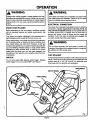
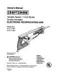
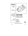
Before attempting to use your planer, familiarize yourself
with all operating features and safety requirements. See
Figure 1.
Your planer is compact, lightweight, and equipped with a
depth adjusting knob located at the front of your unit.
When used properly, your planer should take the guesswork
out of planing, sizing, or beveling of doors, windows, shutters, drawer slides, and other work. However, as with any
powerful, high-speed tool, your planer requires accurate setups and handling. Practice cutting on scrap lumber before
attempting to plane finished stock. In order to turn out the
quality work for which your tool has been designed, the
importance of the need for you to practice cannot be overemphasized.
SWITCH
To turn your planer ON, depress switch trigger. Release
switch trigger to turn your planer OFF. See Figure 1.
CONNECTION
Your planer has a precision built electric motor. It should be
connected to a power supply that is 120 volts, 60 Hz, AC
only (normal household current). Do not operate this tool
on direct current (DC). A voltage drop of more than 10
pement will cause a loss of power and the motor will
overheat. If your tool does not operate when plugged into
an outlet, double-check the power supply.
, WARNING:
Do not allow familiarity with your planer to make you
careless. Remember that a careless fraction of a second
is sufficient to inflict severe injury.
I
CHIP EXHAUST
A chip exhaust has been provided on the exhaust port ofyour
planer. The chute on the chip exhaust can be rotated 90 ° with
positive stops at 0 °, 30 °, 60 ° and 90 ° for deflecting wood
chips away from the operator and workpiece.
REARHANDLE
SWITCHTRIGGER
FRONTHANDLE
CHIPEXHAUST
k
Page 5
OPERATION
WARNING:
Your planer should never be connected to power supply
when you are assembling parts, making adjustments,
changing belts or blades, when cleaning, or when not in
use. Disconnecting your planer will prevent accidental
starting that could cause serious injury.
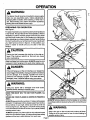
PREPARING
FOR
OPERATION
See Figure 1.
For ease of operation your planer has both a front handle and
a rear handle. This provides for two-hand operation, which is
necessary in order to maintain proper control of your planer
and keep both hands clear of the blades and cutting area.
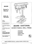
When operating your planer always use both hands holding
the front handle with your left hand and the rear handle with
your right hand as shown in figure 2. In this position, your
planer is easier to handle and you are clear of the chip
exhaust.
__/_
_T-'_X"
_
Fig. 2
CAUTION:
0NG
| Planing too fast increases chip build-up in the chip ex| haust. Chip build-up restricts air flow and can cause
motor overheating.
Keep cord away from cutting area. ALWAYS place the cord
to prevent it from hanging on the work while making a cut.
....
I DANGER:
|
|
|
|
3
Ifthe cord hangs up on the work during a cut, release the
switch trigger immediately. Unplug your planer and check
cord for damage. If no damage, reposition the cord to
prevent it from hanging up again. If the cord has been
damaged, have it replaced before using your planer.
| Using your planer with a damaged cord could cause
electrical shock resulting in serious injury.
o
KNOW THE RIGHT WAY TO USE YOUR PLANER. See
Figure 2.
NEVER USE YOUR PLANER AS SHOWN IN FIGURES 3
AND 4.
ALWAYS keep control of your planer. It makes cutting easier
and safer. To help keep control, always support your work so
the cut will be on your right. Clamp your work so it will not
move during the cut. See Figure 2. The work moving dudng
a cut could result in the loss of control of your planer possibly
causing serious injury.
ALWAYS operate your planer with the chip exhaust turned
away from your face and eyes. All visitors should wear safety
glasses and be kept a safe distance from work area.
Page
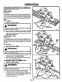
Fig. 4
ALWAYS hold your planer so that the blades do not contact
the workpiece before depressing the switch and starting your
)laner.
WARNING:
Keep a firm grip on the tool with both hands at all times,
Failure to do so could result in loss of control leading to
possible serious injury.
i
i
OPERATION
TO ADJUST PLANING DEPTH
See Figure 5.
UNPLUG YOUR PLANER.
WARNING:
Planing depth is adjustable from 0 to 1/16 inch and is
adjusted by rotating the depth adjusting knob located on the
front of your planer. See Figure 5. To increase cutting depth,
rotate knob clockwise. To decrease cutting depth, rotate
knob counterclockwise. It is recommended that test cuts be
made in scrap wood after each adjustment to make sure that
the desired amount of wood is being removed by your planer.
NOTE: TO PROTECT
BLADES DURING STORAGE,
TRANSPORTING,
ETC., SET BLADE DEPTH ADJUSTMENT TO 0.
GENERALCU'I-rlNG
Adjust your planer to desired depth of cut. WITH YOUR
LEFT HAND HOLDING THE FRONT HANDLE AND YOUR
RIGHT HAND HOLDING THE REAR HANDLE, place front
shoe on workpiece. Make sure blades are not touching the
work. Apply pressure to the front handle so that the front
shoe isflat on the work. Pull switch trigger to start your planer
and let the motor reach maximum speed. Hold your planer
firmly and push forward steadily into your work. NOTE: Push
planer forward slowly if a smooth cut is desired. As the end
of the planed cut is reached, apply downward pressure
toward the rear handle. This will help keep the rear section
of the base in contact with the work preventing the front of
your planer from dipping or gouging your cut. Be careful to
avoid hitting nails during planing operation. This could nick,
crack or damage blades. We suggest that you keep an extra
set of blades on hand. As soon as the blades in your planer
show signs of becoming dull, replace them.
NOTE: THE BLADES IN YOUR PLANER ARE REVERSIBLE, THEREFORE THEY CAN BE ROTATED UNTIL
BOTH SIDES BECOME DULL.
EDGE PLANING
See Figure 6.
(CHAMFERING)
Your planer has been designed with a groove in the front
shoe.
The purpose for this groove is chamfering edges of boards
as shown in Figure 6. Practice cutting on scrap lumber to
determine the amount to be removed from the board, before
making a cut on good lumber. FIRMLY HOLDING THE
FRONT HANDLE WITH YOUR LEFT HAND AND THE
REAR HANDLE WITH YOUR RIGHT HAND, place the
groove on the surface to be cut, start your planer and let it
reach full speed, then slowly move it into the work. Maintain
downward pressure to keep your planer flat at the beginning
and the end of the work surface.
Page 7
OPERATION
Packed with your planer to make it a more versatile tool, is
an EDGE GUIDE, RABBETING PLATE, and DOOR BEVEL
FENCE. See Figures 7, 8, and 9.
EDGE GUIDE
See Figure 7.
The edge guide packed with your planer easily attaches to
either side of your planer and is useful when planing long and
uneven surface boards. When making cuts using your edge
guide, the guide should be held firmly against the edge of the
board.
TO A'I'FACH
1.
UNPLUG YOUR PLANER.
WARNING:
2.
Insert the screw provided through the hole in the edge
guide and secure it into screw hole on either side of the
main shoe. See Figure 7.
RABBETING PLATE
See Figure 8.
The rabbeting plate packed with your planer attaches to the
right side of you rplaner and can be used to make rabbet cuts
up to 3/16 inch deep. The maximum width of cut is 11/32 inch
per cut.
MAIN
SHOE
TO ATrACH
1.
UNPLUG YOUR PLANER,
WARNING:
Failure to unplug your planer could result in accidental
starting causing serious injury.
2.
Insert the screw provided through flat washer, then
through the slot in the rabbeting plate.
3.
Next, insert screw into scraw hole on the right side ofthe
main shoe and tighten securely.
TO ADJUST
1.
DEPTH
OF RABBET
5° RELIEF
CUT:
UNPLUG YOUR PLANER.
WARNING:
Failure to unplug your planer could result in accidental
starting causing serious injury.
2.
Place your planer on a flat board or workpiece.
3.
Loosen screw and position the bottom surface of the
rabbeting plate above the board the same distance as
the desired depth of cut. See Figure 8.
4.
Tighten screw securely.
Page 8
OPERATION
NOTE: When making a rabbet cut, place the notch located
on the inside of the main shoe firmly against the side of the
board as shown in figure 8. The rabbeting plate should also
be pressed firmly against the top surface of the beard.
10'POWERCORD
DOOR BEVEL FENCE
See Figure 9.
MOLDEDCORDCLIP
The door bevel fence packed with your planer also attaches
to the right side of your planer and automatically provides a
five degree relief on the edge of a door.
TO A'I'rACH
1.
UNPLUG YOUR PLANER.
WARNING:
Failure to unplug your planer could result in accidental
starting causing serious injury.
2.
3.
PosiUondoor bevel fence as shown in figura 9 and align
with screw holes on the right side of main shoe.
Fig. 10
Insert screws and tighten securely.
Adjust your planer to desired depth of cut. WITH YOUR
LEFT HAND HOLDING THE FRONT HANDLE AND YOUR
RIGHT HAND HOLDING THE REAR HANDLE, place front
shoe on workpiece. Make sure blades are not touching the
work. Apply pressure so that the door bevel fence is firmly
against workpiece, allowing for the desired five degree relief.
Pull switch trigger to start your planer and let the motor reach
maximum speed. Hold your planer firmly and push forward
steadily into your work.
POWER CORD
See Figure 10.
Your planer has a new extra-long 10' power cord that stays
soft and flexible in cold weather. The plug design is shaped
so that it won't snag on your work during use. A molded cord
clip on the plug makes cord storage easier.
ACCESSORIES
THE FOLLOWING RECOMMENDED ACCESSORIES ARE
CURRENTLY AVAILABLE AT SEARS RETAIL STORES.
Blades (item No. 917323)
WARNING:
The use of attachments or accessories not listed above might be hazardous.
Page 9
MAINTENANCE
WARNING:
WARNING:
When servicing use only identical Craftsman replacement
pads. Use of any other parts may create a hazard or
cause product damage.
Always wear safety goggles, or safety glasses with side
shields dudng power tool operation or when blowing dust.
If operation is dusty, also wear a dust mask.
i
i
I
GENERAL
EXTENSION
Only the parts shown on parts list, page 15, are intended to
be repaired or replaced by the customer. All other parts
represent an important part of the double insulation system
and should be serviced only by a qualified Sears service
technician.
The use of any extension cord will cause some loss of power.
To keep the loss to a minimum and to prevent tool
overheating, use an extension cord that is heavy enough to
carry the current the tool will draw.
Avoid using solvents when cleaning plastic pads. Most
plastics are susceptible to various types of commercial
solvents and may be damaged by their use. Use clean cloths
to remove did, carbon dust, etc.
CORDS
A wire gauge size (A.W.G.) of at least 16 is recommended
for an extension cord 100 feet or less in length. When working
outdoors, use an extension cord that is suitable for outdoor
use. The cord's jacket will be marked WA.
CAUTION:
WARNING:
Do not at any time let brake fluids, gasoline, petroleumbased products, penetrating oils, etc. come in contact
with plastic pads. They contain chemicals that can
damage, weaken, or destroy plastic.
When electdc tools are used on fiberglass boats, sports cars,
wallboard, spackling compounds, or plaster, it has been found
that they are subject to accelerated wear and possible
premature failure, as the fiberglass chips and grindings are
highly abrasive to bearings, brushes, commutators, etc.
Consequently it is not recommended that this tool be used
for extended work on any fiberglass material, wallboard,
spackling compounds, or plaster. During any use on these
materials, it is extremely important that the tool is cleaned
frequently by blowing with an air jet.
' Keep extension cords away from any planing area and
position the cord so that it will not get caught on lumber,
I tools, etc., during planing operation.
WARNING:
LUBRICATION
All of the bearings in this tool are lubricated with a sufficient
amount of high grade lubricant for the life of the unit under
normal operating conditions. Therefore, no further lubrication
is required.
Page 10
MAINTENANCE
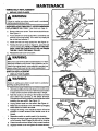
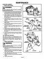
TIMING BELT REPLACEMENT
1.
UNPLUG YOUR PLANER.
WARNING:
SMALL PULLE'
Failure to unplug your planer could result in accidental
starting causing serious injury.
BELTCOVER
WHEN REPLACING TIMING BELT, USE RECOMMENDED
REPLACEMENT BELT ONLY. See Parts List, Page 15.
2.
Remove belt cover screw. Then remove the belt cover.
See Figure 11.
3.
Force old belt from small pulley with a screwdriver and
remove it from large pulley. If it is worn out, simply cut
the old belt and remove it.
.
SCREW
TIMING
LARGEPULLEY
Fig. 11
Install new belt over large pulley first. See Figure 12.
5.
Holding the belt as shown in figure 12, press the belt
onto the small pulley. NOTE: TO SIMPLIFY THE PROCESS, TURN THE LARGE PULLEY AS YOU PRESS
THE BELT ONTO THE SMALL PULLEY.
6.
Reassemble belt cover and screw.
LARGEPULLEY
WARNING:
Belt cover is part of the double insulated system. To retain
electrical insulation and provide user protection as provided in the original design, never attempt to operate your
planer without belt cover and all parts reassembled.
i
SWITCH REPLACEMENT
1.
Fig. 12
LARGEPULLEY
UNPLUG YOUR PLANER.
WARNING:
Failure to unplug your planer could result in accidental
starting causing serious injury.
2.
Remove the eight screws that secure the handle cover
and carefully lift it from the tool. Note the exact location
of each screw since the screw sizes vary in length.
3.
Note the location of all wiring in the handle and where
each switch lead connects to the switch terminals.
Connections and wiring position must be identical when
installing the new switch. See Figure 13.
4.
5.
Unplug switch leads from the switch. See Figure 14.
Make lead connections to the new switch by plugging
switch leads into switch terminals.
6,
Arrange the wiring in the handle so that it will not be
pinched or contact screws when handle cover is replaced.
7.
ReposiUon switch on switch posts in the housing.
8.
Replace the switch trigger and spring ifthey have fallen
out of housing. Switch trigger fits above lip on housing.
Piece the ccrd and bend relief in their correct locations.
9.
10,
Replace handle cover and tighten all screws securely,
Page 11
BLACKMOTORLEAD
BLACK
CORI
SWITCH
MAINTENANCE
CORD REPLACEMENT
I.
UNPLUG YOUR PLANER.
WARNING:
Failure to unplug your planer could result in accidental
starting causing serious injury.
1
2.
Remove the eight screws that secure the handle cover
and carefully liftit from your tool. Note the exact location
of each screw since the screw sizes vary in length.
3.
Note the locations of all wiring in the handle and how
each connection is made to the cord. Connections and
wiring position must be identical when installing new
cord. See Figure 15.
.
Plug the black cord lead of the new power cord into the
switch terminal.
6.
Connect the white cord lead to the white motor lead and
secure with the wire nut.
7.
Arrange the wiring in the handle so that it will not be
pinched or contact screws when handle cover is replaced.
8.
Reposition switch on switch posts in the housing.
9.
Replace the switch trigger and spring ifthey have fallen
out of the housing. Switch trigger fits above the lip on
the housing.
Place the cord and bend relief in their correct locations.
11.
BLACK
CORDLEAD
Unplug the black cord lead from the switch, then disconnect the white cord lead from the wire nut. See
Figure 16.
5.
10.
Fig. 15
SWITCH
MOTOR
HOUSING
WITH BENDRELIEF
WHITE
CORDLEAD
WIRE NUT
WHRE
MOTORLEAD
Fig. 16
Replace handle cover and screws. Tighten all screws
securely.
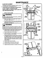
TO CLEAN CHIP EXHAUST
After using your planer for an extended period of time or
when planing wet or green lumber, chips will build-up in the
chip exhaust and require cleaning. This chip build-up restricts air flow and causes motor overheating. Clean as
follows:
1.
UNPLUG YOUR PLANER.
CLEAN
EXHAUSTPORT
WARNING:
Failure to unplug your planer could result in accidental
starting causing serious injury.
2.
Remove the two chip shield screws and chip shield.
See Figure 17.
3.
Clean the chip build-up from the exhaust port on your
planer with a dowel pin or small piece ofwood. DO NOT
use your hands or fingers.
Clean chips and chip build-up from the chip shield.
Clean chip shield with a soft, dry cloth,
4.
5.
Replace chip shield and secure with the two chip shield
screws.
6.
Tighten screws securely.
Page12
SCREWS
CHIPSHIELD
Fig. 17
J
MAINTENANCE
BLADE REPLACEMENT
The blades in your planer are reversible. Therefore, they can
be reversed when one edge becomes dull.
ALWAYS REPLACE OR REVERSE BLADES IN PAIRS.
DO NOT A'I-rEMPT TO SHARPEN BLADES.
NEVER ATTEMPT TO OPERATE YOUR PLANER WITH
ONLY ONE BLADE INSTALLED.
1.
UNPLUG YOURPLANER.
WARNING:
I
Failure to unplug your planer could result in accidental
starting causing serious injury.
2.
Place your planer in an upside
work bench. See Figure 18.
down position
on
3.
To prevent rotation of the arbor while changing the
blades, place a small piece of wood between the arbor
and the base. See Figure 18.
BLADE
WARNING:
CUTTER
BLADE
Remove the piece of wood before restarting your planer.
Failure to do so could result in the piece of wood being
thrown from your planer causing possible serious injury.
k
4.
Using the 5/32 in. allen wrench provided, remove the
three (3) screws securing blade. See Figure 19.
5.
Remove blade clamp and cutter blade.
6.
Clean any sawdust or wood particles from cutter arbor
and from all parts you have removed.
7,
Place new cutter blade over plastic Iocators. See Figure
20. NOTE: Place front of cutter blade slots so that they
touch plastic Iocators. Do not move or adjust plastic
Iocators. They have been factory adjusted to assure
proper depth setting is maintained and that the blades
remain parallel.
8.
Replace blade clamp and screws.
9.
Securely tighten all screws with allen wrench.
10.
Remove the piece of wood from your planer.
11.
Repeat the above procedure to change the other blade.
CUTTER
CUTTER
]LADE SLOTS
_"PLASTIC
LOCATORS
Fig. 19
CUTTER
BLADE
PLASTIC
LOCATORS
\
®
®
Page 13
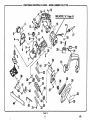
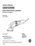
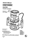
CRAFTSMAN
INDUSTRIAL
PLANER
-- MODEL NUMBER
315.277160
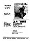
14.1% %---12
SEE NOTE "A", Page 15
15
I
13
28
26
41
Page 14
25
24
CRAFTSMAN
[
INDUSTRIAL
PLANER
-- MODEL
NUMBER
315.277160
The model number will be found on a plate attached to the motor housing. Always mention the model number in all correspondence
PLANER or when ordering repair parts.
SEE BACK PAGE FOR PARTS ORDERING
regarding your
|
I
INSTRUCTIONS
PARTS LIST
Key
No.
1
2
3
4
5
6
7
8
9
10
11
12
13
14
15
16
17
18
19
20
21
22
23
Part
Number
972482-003
972492-001
606872-001
610122-003
972475-001
972474-001
972480-005
970627-001
970700-001
931744-822
972711-000
617966-028
972483-000
617966-031
617966-015
972488-001
970777-015
623173-007
971492-001
972481-001
971474-001
065501-190
977222-001
Description
Key
No.
Quan.
Front Shoe ..............................................................
Rubber Plate ...........................................................
Adjustment Spring ...................................................
Screw (#8-32 x 3/8 In. Pan Hd. T.C) .......................
Chip Exhaust Extension ..........................................
Chip Exhaust ...........................................................
Main Shoe ...............................................................
Spring ......................................................................
Detent Button ..........................................................
Washer ....................................................................
Knob With Indicator ................................................
Screw (#8-10 x 1/2 In. Pan Hd.) .............................
Handle With Cover ..................................................
Screw (#8-10 x 3/4 In. Pan Hd.) .............................
Screw (#8-10 x 1 In. Pan Hd.) ................................
Data Plate ...............................................................
Cord ........................................................................
Wire Nut ..................................................................
Spring ......................................................................
Switch Trigger .........................................................
Switch Actuator .......................................................
Switch .....................................................................
Logo Plate ...............................................................
1
1
1
2
1
1
1
1
1
1
1
2
1
7
1
1
1
1
1
1
1
1
1
24
25
26
27
28
29
30
31
32
33
34
35
36
37
38
39
40
41
42
43
44
Part
Number
606856-004
973831-001
607139-002
622163-010
610183-202
606627-201
703432-058
610878-002
999682-003
967039-000
610389-002
706239-836
621585-002
622149-055
620789-007
606873-001
621431-008
931744-815
606866-001
820193-011
610988-002
972000-115
Description
Quan.
Belt Cover ...............................................................
Timing Belt ..............................................................
Pulley ......................................................................
Screw (#8-32 x 5/16 In. Pan Hd.) ...........................
Cutter Head Support ...............................................
Blow Guide ..............................................................
Screw (#8-32 x 5/8 In. Fil Hd.) ................................
Screw (#1/4-20 x 1/2 In. Button Hd.) ......................
Blade Clamp ...........................................................
Blade (Item No. 9-17323) .......................................
Cutter Head Assembly ............................................
Washer ....................................................................
1
1
1
4
1
1
5
6
2
1
1
1
Ball Searing (NTN#6200LLBC3/1E)
.......................
Ball Bearing (NTN#629LBZC3/1 E) .........................
Washer ....................................................................
1
1
1
Edge Guide .............................................................
* Screw (#10-24 x 3/8 In. Fil. Hd.) .............................
Washer **STD551010 .............................................
Rabbeting Plate ......................................................
* 5/32 In. Hex Socket Key (Item No. 9-28173) ..........
Door Bevel Fence ...................................................
Owner's manual
1
2
1
1
1
1
*
*
*
***
NOTE: "A"-- The assembly shown represents an important part of the Double Insulated System. To avoid the possibility of alteration or damage
to the system, service should be performed by your nearest Sears Repair Center. Contact your nearest Sears Retail Store for Service Center
information.
* Standard Hardware Item -- May Be Purchased Locally.
** Available From Division 98 - Source 980.00
*** Available At Your Nearest Sears Retail Store.
Page15
For repair of major brand appliances in your own home...
no matter who made it, no matter who sold it!
1-800-4-MY-HOME
sMAnytime, day
or night
(1-800-469-4663)
www.sears.com
To bring in products such as vacuums, lawn equipment and electronics
for repair, call for the location of your nearest Sears Parts & Repair Center.
1-800-488-1222
Anytime,
day or night
www.sears.com
For the replacement parts, accessories and owner's manuals
that you need to do-it-yourself, call Sears PartsDirect sM!
1-800-366-PART
(1-800-366-7278)
6am - 11p.m.CST,
7 days a week
www.sears.corn/partsdirect
To purchase
or inquire about a Sears Service Agreement:
1-800-827-6655
7 a.m. - 5 p.m. CST, Mon.Para pedir servicio de reparacibn a domicilio,
y para ordenar piezas con entrega a domicilio:
1-888-SU-HOGAR
s.
Sat.
Au Canada pour service en franc...ais:
1.877.LE-FOYER
_
(1-877-533-6937)
,____{-.,}
(1 °888-784-6427)
HomeCentral
® Registered Trademark /
® Sears, Roebuck and Co,
TM
Trademark of Seam, Roebuck and Co,
® Mama Registrada / "r. Marca de Fdbrica de Seam, Roebuck and Co.