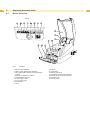
1
Service Manual from Serial No. 10000 Barcode / Label Printer MACH4 The Business Class. 2 Service Manual for the following products 2 Part No. Description Type 5541082 Transfer printer MACH4/200B 5541083 Transfer printer MACH4/300B 5541086 Transfer printer MACH4/600B 5541092 Transfer printer MACH4/200P 5541093 Transfer printer MACH4/300P 5541096 Transfer printer MACH4/600P 5541102 Transfer printer MACH4/200C 5541103 Transfer printer MACH4/300C 5541106 Transfer printer MACH4/600C Edition: 2/2008 - Part No. 9008600 Copyright This documentation as well as translation hereof are property of cab Produkttechnik GmbH & Co. KG. The replication, conversion, duplication or divulgement of the whole manual or parts of it for other intentions than its original intended purpose - in particular the procurement of spare parts for products sold by cab - demand the previous written authorization by cab. Trademark Centronics® is a registered trademark of the Data Computer Corporation. Microsoft® is a registered trademark of the Microsoft Corporation. Windows 2000®, 2003®, XP® are registered trademarks of the Microsoft Corporation. TrueTypeTM is a registered trademark of Apple Computer, Inc. Editor Regarding questions or comments please contact cab Produkttechnik GmbH & Co. KG. Topicality Due to the constant further development of our products discrepancies between documentation and product can occur. Please check www.cabgmbh.com for the latest update. Terms and conditions Deliveries and performances are effected under the General conditions of sale of cab. Germany cab Produkttechnik GmbH & Co KG Postfach 1904 D-76007 Karlsruhe Wilhelm-Schickard-Str. 14 D-76131 Karlsruhe Telefon +49 721 6626-0 Telefax +49 721 6626-249 www.cab.de [email protected] France cab technologies s.a.r.l. F-67350 Niedermodern Téléphone +33 388 722 501 USA cab Technology Inc. Tyngsboro MA, 01879 Phone +1 978 649 0293 www.cab.de [email protected] www.cabtechn.com [email protected] España cab España S.L. E-08304 Montaró (Barcelona) Teléfono +34 937 414 605 South Afrika cab Technology (Pty.) Ltd. 2125 Randburg Phone +27 11-886-3580 www.cab.de [email protected] www.cab.de [email protected] Representatives in other countries on request. Asia cab Technology Co, Ltd. Junghe 23552, Taipei, Taiwan Phone +886 2 8227 3966 www.cabasia.net [email protected] cab (Shanghai) Trading Co.,Ltd 2299 11C60 Phone +86 21 6236-3161 [email protected] Table of Contents 1 1.1 1.2 1.3 1.4 Important Information............................................................................................................................. 4 General Safety Instructions....................................................................................................................... 4 Protective Devices.................................................................................................................................... 4 Handling Electricity .................................................................................................................................. 5 Procedure in Case of Accidents ............................................................................................................... 5 2 2.1 2.2 2.3 2.4 2.5 2.6 2.7 2.8 2.9 2.10 2.11 2.12 2.13 Replacing Assembly Units..................................................................................................................... 6 Device Overview....................................................................................................................................... 6 Tools.......................................................................................................................................................... 7 Replacing the Control Panel..................................................................................................................... 8 Replacing the Cover.................................................................................................................................. 9 Replacing the Outer Casing.................................................................................................................... 10 Replacing the Print Mechanism...............................................................................................................11 Replacing the Printhead.......................................................................................................................... 12 Replacing the Print Roller....................................................................................................................... 13 Replacing the Brake of the Ribbon Supply Hub...................................................................................... 14 Replacing the Drive of the Cutting Unit................................................................................................... 15 Replacing the Blades of the Cutting Unit................................................................................................ 16 Replacing the CPU PCB......................................................................................................................... 17 Replacing the Power Unit........................................................................................................................ 18 3 3.1 3.2 3.3 Adjustments.......................................................................................................................................... 19 Measuring the Winding Torques.............................................................................................................. 19 Adjusting the Winding Torques................................................................................................................ 20 Adjusting the Print Mechanism................................................................................................................ 21 4 Block Diagram....................................................................................................................................... 23 5 Index....................................................................................................................................................... 24 3 4 1 Important Information 1.1 General Safety Instructions This service manual is intended for use by qualified service and maintenance personnel. For more operation and configuration information, refer to the user or configuration manual. Follow the general safety rules below: • Keep the area around the device clean at all times! • Work with safety in mind. • Parts of device that are removed during the maintenance work must be put in a safe place. • Avoid risks of tripping over. Danger! Danger to life and limb from increased current flow through metal parts in contact with the device. XX Do not wear clothing with metal parts. XX Do not wear jewelry. XX Do not wear spectacles with metal frames. ! 1.2 ! Warning! Items of clothing drawn into the device by moving parts can lead to injuries. XX Do not wear any items of clothing which could get caught by moving parts. Protective Devices Warning! There is a risk of injury if protective devices are missing or defective. XX Replace all protective devices (covers, safety notices, grounding cables etc) after maintenance work has been completed. XX Replace parts that have become defective or unusable. Wear protective goggles for: • Knocking pins or similar parts in or out with a hammer. • Using spring hooks. • Inserting or removing springs, retaining rings or grip rings. • Using solvents, cleansers or other chemicals. 4 1 Important Information 1.3 Handling Electricity The following work may only be done by trained and qualified electricians: • Work on electrical components. • Work on an open device still connected to the mains supply. General precautions before starting maintenance work: • Find out where the emergency and power switches are so that they can be quickly thrown in an emergency. • Disconnect the current supply before carrying out the following work: -- Installing or removing power units. -- Working in the immediate vicinity of open power supply components. -- Mechanical check of power supply components. -- Modifying circuits in the device. • Test the zero potential of the device parts. • Check the working area for possible sources of danger, such as wet floors, defective extension cables, defective protective conductor connections. Additional precautions in the case of exposed voltages: • Ask a second person to remain near the working site. This person must know where the emergency and power switches are, and how to switch the current off if danger arises. • Only use one hand to work on electric circuits of devices that are switched on. Keep the other hand behind your back or in your pocket. This prevents electricity from flowing through your own body. 1.4 Procedure in Case of Accidents • Act calmly and with great care. • Avoid danger to yourself. • Switch off power. • Request medical assistance. • Give first aid, if necessary. 5 6 2 Replacing Assembly Units 2.1 Device Overview 6 View A 1 2 3 4 5 6 7 8 9 10 11 13 16 15 12 14 A Fig. 1 Overview 1 RS-232 serial interface 2 USB 2.0 High Speed Slave interface 3 Two USB master interfaces for keyboard and scanner 4 Ethernet 10/10 Base T interface 5 CompactFlash card slot 6 Power supply socket 7 PC card slot, type II 8 Power switch 9 Cover 0Roll hub 1 11 Holder slots 12Ribbon rewind hub 13Printhead mounting with printhead 14Release button of the print module 15Pressure roller 16Control panel 2 Replacing Assembly Units 2.2 Tools • Do not use any worn of damaged tools. • Only use tools and testing devices that are suitable for the task at hand. cab special tools: • Tape holder test collar (cab item number: 5540932) • Assembling aid (cab item number: 5541180) • Cylindrical dynamometer (spring scale), 0 - 10 N (cab item number: 5906108) Standard tools: • Screw driver Torx, size TX 10/200 • Hex screwdriver, straight, size 2.5 • Screwdriver with flat blade, size 4 • Flat-nose pliers 7 8 2 Replacing Assembly Units 2.3 Replacing the Control Panel 1 Fig. 2 2 3 4 2 8 5 3 Replacing the control panel 1 Control panel 2 Lug 3 Bearing i 4 Plug connector 5 Axle Notice! When replacing Control Panel B or P by a Control Panel C in order to convert the printer to the cutter version the peel-off edge must be removed. To convert the printer in the opposite direction the peel-off edge must be inserted ( 2.8 on page 13). 1. Hinge down the control panel (1). 2. Hold the device with one hand, grip the control panel with the other hand, and remove one axle (5) from its bearing (3) by pulling strongly. 3. Grip the control panel above the second axle, and pull it until the axle comes out of its bearing. i Notice! Ensure that the plug connector (4) is not damaged. 4. Draw the lugs (2) beside the bearings (3) out of the device. 5. Pull the plug (4) out of the printer, and put down the control panel. 6. Put the plug (4) of the new control panel into the printer. 7. Draw the lugs (2) beside the bearings (3). 8. Tilt the control panel upwards a little. 9. Hook the axles (5) into their bearings. 10.Press firmly on the control panel until the axles audibly slot into their bearings. 2 Replacing Assembly Units 2.4 Replacing the Cover 1 Fig. 3 2 3 9 5 4 6 7 4 Replacing the cover 1 Toothed lug 2 Damping wheel 3 Hinged aperture cover 4 Axle 5 Cover 6 Locking ring 7 Guide for outer casing 1. Open the cover (5), remove the media hub and label stock. 2. Disconnect the damping mechanism by pressing both toothed lugs (1) towards the center of the device. 3. Press the cover further back until the axles (4) come out of the guide (7). 4. To fit the new cover, first remove the locking rings (6) and the axles (4). 5. Place a new cover (5) on the casing, ensure that the damping wheels (2) mesh with the toothed lugs (1). 6. Push the axles (4) on both sides from the inside into the hinged aperture (3). 7. Close the cover. 8. Attach the locking rings (6). 10 2 Replacing Assembly Units 2.5 Replacing the Outer Casing 10 Danger! Danger to life and limb from electric shock! XX Disconnect the device from the mains supply before opening the outer casing. 1 Fig. 4 2 3 4 Replacing the outer casing 1 Two screws 2 Outer casing 3 Two Screws 4 Cover The outer casing can be removed complete with the cover. 1. Open the cover (4), remove the roll hub and material. 2. Unscrew 2 screws (1) from the front of the casing. 3. Unscrew 2 screws (3) from the inside of the floor. 4. Remove the outer casing (2) together with the cover (4). Mount the outer casing with the cover in the reverse order. Hinge up the print module for easier inserting the parts. 2 Replacing Assembly Units 2.6 Replacing the Print Mechanism 11 Danger! Danger to life and limb from electric shock! XX Disconnect the device from the mains supply before opening the outer casing. 1 2 9 3 8 4 7 5 6 Fig. 5 Replacing the print mechanism 1 Print mechanism 2 Cables 3 Grounding cable 4 CPU PCB 5 Screw 6 Screw 7 Bottom guide 8 Elongated hole 9 Lug 1. Remove the outer casing with the cover ( 2.5 on page 10). 2. Disconnect the print mechanism cables (2) from the CPU PCB (4). 3. Remove the grounding cable (3) with the screw (6) from the CPU PCB (4). 4. Loosen the two screws (5). Slide the print mechanism (1) back a little until the elongated holes (8) can be lifted off from the two screws (5). Pull the lower lugs (9) out of the bottom guides (7) and put the print mechanism down. 5. Slide the lower lugs (9) of the new printing mechanism into the bottom guides (7), press down, and slide forward until it slots into the projections beside the screws. Tighten both screws (5). 6. Attach the grounding cable (3) to the CPU PCB (4) with the screw (6). 7. Connect the cables (2) with the CPU PCB ( 2.7 on page 12). 8. Remount the outer casing with the cover ( 2.5 on page 10). 12 2 Replacing Assembly Units 2.7 Replacing the Printhead 12 Danger! Danger to life and limb from electric shock! XX Disconnect the device from the mains supply before opening the outer casing. 1 Fig. 6 3 4 5 6 7 Replacing the printhead 1 Two holes 2 Two pins 3 Screw 4 Printhead ! 2 5 Printhead cable 6 Printhead mounting 7 Printhead cable Warning! Protect the printhead against damage by electrostatic discharge! XX Put the printer on to a grounded conductive surface! XX Ground yourself during printhead replacement for example using a grounded wrist-strap! XX Do not touch the connector pins of the printhead by naked hands! 1. Open the cover and hinge down the control panel, press the release button and hinge up the print module. 2. Disengage the printhead (4) from the printhead mounting (6) by unscrewing the screw (3). 3. Remove the printhead cables (5) and (7) from the printhead (4). 4. After exchanging the printhead (4), attach the printhead cables (5) and (7) to the new printhead. 5. Attach the printhead (4) to the printhead mounting (6) by the screw (3). i Notice! Ensure that the pins (2) at the printhead reach into the holes (1) of the printhead mounting. 6. Hinge down the print module and press evenly on the two marked surfaces so that the unit snaps in on both sides. Close the control panel. 2 Replacing Assembly Units 2.8 Replacing the Print Roller 13 Danger! Danger to life and limb from electric shock! XX Disconnect the device from the mains supply before opening the outer casing. 50 40 30 20 10 0 10 50 1 Fig. 7 2 3 4 5 6 Replacing the print roller 1 Apertures 2 Holding lugs 3 Print roller unit 4 Roller holder 5 Peel-off edge 6 Print roller 1. Open the cover and hinge down the control panel, press the release button and hinge up the print module. 2. Release the locking device to remove the print roller unit (3): Insert a pointed tool through the apertures (1) on both sides, press on the pressure points of the holding lugs (2), and release the print roller unit (3). A soft click will be heard and the print roller unit (3) rises slightly. Pull the released print roller unit (3) upwards out of the device. 3. Pull the roller holder (4) and the peel-off edge (5) off the print roller (6) and insert both into the new print roller. i Notice! Printers with cutting unit are not equipped with peel-off edge (5). 4. Insert the print roller unit (3) into the holder apertures, and press down evenly on both sides until it latches in. 5. Hinge down the print module and press evenly on the two marked surfaces so that the unit snaps in on both sides. Close the control panel. 14 2 Replacing Assembly Units 2.9 Replacing the Brake of the Ribbon Supply Hub Fig. 8 14 Replacing the coupling brake of the ribbon supply hub 1 Ribbon supply hub 2 Cover 3 Three screws 4 Brake 5 Coupling mounting tool 6 Holder 7 Lock washer 1. Hinge up the printhead assembly, unscrew the three screws (3), and remove the cover (2). 2. For easier handling: -- Ensure that the hub (1) is attached. -- Press the holder (6) of the friction coupling inwards, turn it into the position 1 and release. Ensure that the locking lugs have been fully inserted into the recesses of the holder. 3. Grip the hub (1) that the axle cannot rotate, press the holder (6) of the friction coupling inwards and turn the lock washer (7) counterclockwise using the assembling aid (5 / Part No. 5541180) until it is released, then take it off. 4. Take off the several elements of the brake and mount the new parts in reverse order. 5. Grip the hub (1) that the axle cannot rotate, press the lock washer (7) in and turn it until it clicks into place noticeable. i Notice! Ensure that the markings of the lock washer (7) are outside. 6. Turn the holder (6) back to it’s original position, measure the winding torque ( 3.1 on page 19) and correct if necessary ( 3.2 on page 20). 7. Re-attach the cover (2) with the three screws (3). 2 Replacing Assembly Units 2.10 Replacing the Drive of the Cutting Unit Fig. 9 15 Replacing the drive of the cutting unit 1 Control panel 2 Two plastic latches 3 Cutting unit 4 Clock wheel 5 Shaft 6 Two eccentrics 7 Two screws 8 Two connectors 9 Two nuts 10Base plate 11 Drive 1. Turn the control panel (1) down, unlock the cutting unit (3) at the both plastic latches (2) and lift it. 2. Loosen the nuts (9). 3. Loosen (but not remove) the two screws (7) carefully so that the connectors (8) can be moved from the pivots of the eccentrics (6). 4. Unlock the two eccentrics (6) and pull they off from the shaft (5). 5. Unlock the clock wheel (4), pull out the shaft (5) from the drive (11) and the base plate (10). 6. Remove the drive (11) and insert the new drive into the form hole of the base plate (10). 7. Assembly in reverse order. i Notice! Ensure that the latches of the two eccentrics (6) and of the clock wheel (4) are positioned as shown in the figure. 16 2 Replacing Assembly Units 2.11 Replacing the Blades of the Cutting Unit Fig. 10 16 Replacing the blades of the cutting unit 1 Control panel 2 Two plastic latches 3 Cutting unit 4 Base plate 5 Screw 6 Three screws 7 Clamp 8 Lower blade 9 Paper guide 10Upper blade 11 Three screws 1. Turn the control panel (1) down and hinge it up ( 2.3 on page 8). 2. Unlock the cutting unit (3) at the both plastic latches (2) and lift it. 3. Turn the screw (5) clockwise using a 2.5 mm Allen key and that way swivel the clamp (7) with the lower blade (8) away from the upper blade (10). ! Danger! Danger of cuts and bruising! XX The springs at the clamp are strongly tight while turning up or down and when it is turned down. Do not reach into the area between the blades. XX Do not touch the blade edges with bare hands. 4. Loosen the three screws (6) of the lower blade (8), remove the blade and attach the new blade with the three screws at the clamp (7). 5. Loosen the three screws (11) of the upper blade (10), remove the blade and the paper guide (9) and attach the paper guide and the new blade with the three screws at the base plate (4). 6. Go on mounting in reverse order. 2 Replacing Assembly Units 2.12 Replacing the CPU PCB 17 Danger! Danger to life and limb from electric shock! XX Disconnect the device from the mains supply before opening the outer casing. 1 2 8 3 9 4 5 6 10 7 Fig. 11 Replacing the CPU PCB 1 Control panel cable 2 Sensors cable 3 Cable for printhead power supply 4 Printhead signal cable 5 Power unit cable 6 Stepping motor cable 7 Grounding cable 8 Grounding cable power input module 9 Screw 10Fan cable 1. Save the printer configuration on a CompactFlash card, the configuration manual. Pull out all memory modules of their slots. 2. Remove the outer casing ( 2.5 on page 10). 3. Disconnect cables (1) to (6) from the CPU PCB. 4. Loosen both screws (9) and the grounding cables (7, 8). 5. Disconnect the fan cable (10) and remove the CPU PCB. 6. Reassemble in the reverse order. 7. Perform a firmware update as required. 8. Load the printer configuration from a CompactFlash card, or set it on the control panel, the configuration manual. 18 2 Replacing Assembly Units 2.13 Replacing the Power Unit 18 Danger! Danger to life and limb from electric shock! XX Disconnect the device from the mains supply before opening the outer casing, and wait at least one minute to allow the power unit to discharge. 1 Fig. 12 2 3 4 5 6 7 8 5 9 Replacing the power unit 1 Power unit cover 2 Base tub latch 3 Screw 4 Recess 5 Screw 6 Power unit cable 7 Power unit 8 Mains input plug 9 Bottom lug 1. Turn the printer and place it on a suitable underlay. 2. Loosen the two screws (3). 3. Insert a screwdriver into the recess (4), lift and remove the cover (1). 4. Unplug the mains input (8) and power unit (6) cables. 5. Remove the two screws (5). 6. Remove the power unit (7). 7. Slide the new power unit (7) under the 3 bottom lugs (9), and slot the power unit PCB, with the drill holes for the screws (5), into the corresponding projections. Then fix in place with the two screws (5). 8. Plug in the mains input (8) and power unit (6) cables again. 9. Hook the cover (1) into the lugs of the base tub (2), and fixate with two screws (3). 3 Adjustments 3.1 Measuring the Winding Torques 19 The winding torques on the ribbon rewind hub and ribbon supply hub are measured by determining the tensile force on the test collar mounted on the hub. The physical relation between torque and traction is as follows: F= M / r F: Traction [N], M: Winding torque [Ncm], r: Radius of test collar (30 mm) The specified values for the winding torque and the resulting traction on the test collar are: Winding torque M Traction F Friction coupling on the ribbon rewind hub Fig. 13 A 14.4 - 17.4 Ncm 4.8 - 5.8 N Brake on ribbon rewind hub Fig. 13 B 2.7 - 4.5 Ncm 0.9 - 1.5 N Friction coupling on the ribbon supply hub Fig. 13 C 3.9 - 4.5 Ncm 1.3 - 1.5 N A B 1 Fig. 13 2 C 3 4 2 3 Measuring the winding torques 1 Ribbon rewind hub 2 Test collar 3 Spring scale 4 Ribbon supply hub Measuring the torque of the coupling on the supply hub: 1. Wind the cord several times round the test collar ( fig. 13 C on page 19) and mount it on the supply hub (4). The spring lugs of the hub must slot into the smaller slot in the test collar. 2. Measure the winding torque for the coupling of the supply hub, and set it in the same way as on the rewind hub. 3 Adjustments 20 Measuring the torque of the coupling and brake on the rewind hub: 1. Wind the cord several times round the test collar ( fig. 13 A on page 19) and mount it on the rewind hub (1). The spring lugs of the hub must slot into the smaller slot in the test collar. 2. Attach a spring scale [10 N] (3) to the end of the cord, raise it vertically until the test collar starts to turn. 3. Allow the cord to unwind at least one full turn from the test collar, and read off the tensile force F for the coupling on the spring scale. 4. Reset the winding torque of the coupling if it differs from the specified value ( 3.2 on page 20). 5. Disconnect the rewind hub (1) from the drive in order to measure the winding torque for the brake. Press the release button, hinge up the printhead assembly, repeat the measuring procedure ( fig. 13 B on page 19). 6. If the winding torque of the brake differs from the specified value, the parts involved must be replaced, they cannot be reset. 3.2 Adjusting the Winding Torques Danger! Danger to life and limb from electric shock! XX Disconnect the device from the mains supply before opening the outer casing. 4 5 6 7 5 3 7 6 2 4 1 3 5 4 6 4 3 3 5 7 6 1 2 5 7 2 4 6 1 3 1 2 Fig. 14 6 5 4 3 6 4 3 5 20 Adjusting the winding torques 1 Knurled ring 2 Locking device 3 Print module 4 Supply hub friction coupling 5 Rewind hub friction coupling 6 Cover 7 Screw 1. Hinge up the print module (3), unscrew screw (7), and remove the cover (6). 2. Press the knurled ring (1) of the friction coupling towards the casing wall, turn it into the desired position and release. Ensure that the locking lugs have been fully inserted into the recesses of the knurled ring. 3. Measure the winding torque again, compare it with the specified value, and correct if necessary. Repeat until the measured winding torque lies within the tolerance range. 4. Reattach the cover (6) with the three screws (7). i Notice! The numbers on the knurled ring are no setting values. They are used for orientation only when setting the winding torque. XX 1: Minimum winding torque, 7: Maximum winding torque 3 Adjustments 3.3 Adjusting the Print Mechanism 21 Major adjustment of the print mechanism beyond format-based settings is only required if the printhead assembly has been removed or parts in this area have been replaced. Excluded from this is the replacement of the printhead, after which readjustment is generally not required. The following print quality imperfections may require a correction of the print mechanism adjustment: -- Print image too light -- Print image is spotty -- Print image lighter on one side -- Horizontal lines not parallel to the horizontal label edges -- Clear lateral drift of the transfer ribbon i 3.3.1 Notice! Print image errors can also arise from wrinkling of the transfer ribbon. Check the transfer ribbon feed path. Adjusting Elements Fig. 15 Printhead adjusting elements 1 Printhead 2 Screws for horizontal alignment 3 Screws for adjusting the printhead pressure 4 Screw for adjusting the printhead bend Screws for horizontal alignment (2) -- Turning the screws clockwise will move the printhead to the front. -- Turning the screws counter-clockwise will move the printhead to the back. For an optimum print quality, the heating elements of the printhead must be aligned to the peak of the print roller. This setting guarantees the best print darkness and the parallelism of printed horizontal lines and the label edge. Screws for adjusting the printhead pressure (3) -- Turning the screws clockwise will decrease the printhead pressure on the corresponding side. -- Turning the screws counter-clockwise will increase the printhead pressure. By turning a screw (3) counter-clockwise and thereby increasing the printhead pressure, the print image will darken at the corresponding side and the transfer ribbon feed will shift to the other side. ! Warning! Be careful while turning the screws (3) counter-clockwise, there is the possibility to screw off the parts completely. 22 3 Adjustments Screw for adjusting the printhead bend (4) • Turning the screw clockwise will slightly bend the middle of the printhead downwards which will increase the printhead pressure in the center. In case the normal methods to prevent ribbon wrinkling are not successful, the printhead can be bent a little bit by turning the screw clockwise. This must be done extremely carefully. Warning! ! Material damage! As soon as a clear resistance is encountered, the screws should not be turned by more than a quarter-turn maximum! As a result, the print image may be lighter on the edges than in the center. 3.3.2 Adjusting 1. Load such media (label and transfer ribbon) which extends over the entire print width. 2. In the Printer Configuration set the heat level to 0 and the print speed to 100 mm/s. 3. Loosen the screw for printhead bending (4) by turning it counter-clockwise until it turns noticeably easy. This should occur after a maximum of half a turn. 4. Print out some test patterns with the test function "Test grid“ or similar test labels. 5. If the horizontal lines in the test grid are not parallel in relation to the label edges adjust the parallelism by turning the screws (2). 6. Turn the screws (3) for the printhead pressure clockwise until they turn noticeably easy. 7. Reduce the heat level in the Printer Configuration until the print image is very light and just recognizable. Under these conditions, adjustment inaccuracies will become clearly visible. 8. Print out some more test patterns with the test function "Test grid“. Increase the printhead pressure on that side where the print image is lighter. Turn the screws (3) counter-clockwise each by a quarter-turn until the print image is even over the entire width. It may be necessary to turn both screws alternately. The darkness of the print image might still not be satisfactory. 9. Turn the screws (2) counter-clockwise and shift the printhead to the back until the print image almost disappears. Now turn the screws (2) clockwise and shift the printhead to the front until the print image reaches the maximum print darkness. Attend to the parallelism of the horizontal lines to the label edge. 10.Now check the ribbon feed. If the ribbon runs to the right turn the right screw (3) counter-clockwise in quarter-turns. If the ribbon runs to the left turn the left screw (3) counter-clockwise in quarter-turns. 11.Check the ribbon feed after each adjustment step and wait until it runs stable. 12.If the adjustment of the ribbon is not successful (for example, if there are wrinkles on both sides at the same time) the printhead must be bent. In order to do that turn screw (4) clockwise. This must be done extremely careful. Warning! ! Material damage! As soon as a clear resistance is encountered, the screw (4) should not be turned by more than a quarterturn maximum! Check the ribbon feed from time to time. Turn only as far as necessary. A slightly lighter print image may be visible on the edges of the labels. If there is no bending required, turn the screw (4) clockwise until the screw jams just a bit. 13.Set the heat level in the Printer Configuration back to 0 and check the result of the adjustments at this setting. Use cab standard material for the test print. Ideally, the printout should show clearly outlined lines and evenly black areas without blanks. 22 4 Block Diagram Fig. 16 Block diagram 1 Fig. 17 Block diagram 2 23 24 5 Index 24 B I R Blades of the cutting unit replacing......................................16 Brake of the ribbon rewind hub winding torque.............................19 Brake of the ribbon supply hub..........14 replacing......................................14 Interface ethernet..........................................6 serial..............................................6 USB...............................................6 Release button of the print module.....6 C CompactFlash card slot.......................6 Control panel.......................................6 replacing........................................8 Coupling on the ribbon rewind hub winding torque.............................19 Coupling on the ribbon supply hub winding torque.............................19 Cover...................................................6 replacing........................................9 CPU PCB..........................................17 replacing......................................17 Cutting unit........................................15 D Device overview..................................6 Drive of the cutting unit replacing......................................15 G General safety instructions..................4 H Handling electricity..............................5 Holder slots.........................................6 M Maintenance work...............................5 O Outer casing......................................10 replacing......................................10 P PC card slot.........................................6 Replacing blades of the cutting unit..............16 brake of the ribbon supply hub....14 control panel..................................8 cover..............................................9 CPU PCB.....................................17 drive of the cutting unit.................15 outer casing.................................10 power unit....................................18 printhead......................................12 print mechanism.......................... 11 print roller.....................................13 Ribbon rewind hub..............................6 Peel-off edge.....................................13 Roll hub...............................................6 Power supply socket...........................6 T Power switch.......................................6 Torque...............................................19 Power unit.........................................18 replacing......................................18 Pressure roller.....................................6 Traction..............................................19 Printhead.......................................6, 12 replacing......................................12 Printhead cable.................................12 Voltages, exposed...............................5 Printhead mounting.......................6, 12 Winding torque brake on the ribbon rewind hub...19 coupling on the ribbon rewind hub.19 coupling on the ribbon supply hub.19 Winding torques adjusting......................................20 measuring....................................19 Print mechanism................................ 11 adjusting......................................22 adjusting elements.......................21 replacing...................................... 11 Print roller..........................................13 replacing......................................13 Print roller unit...................................13 Procedure in case of accidents...........5 Protective devices...............................4 V W