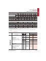
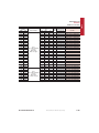
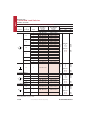
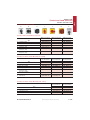
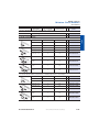
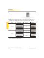
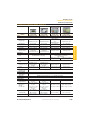
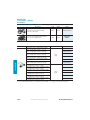
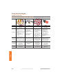
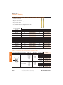
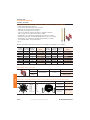
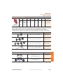
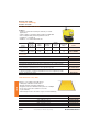
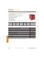
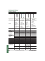
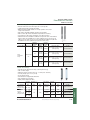
1
Essential Components Get the right components, at the right price, right where you need them. Power Logic Operator Interface Connectivity Safety Sensors & Switches Bulletin Index Bulletin Number Page 100-C ............................................1-31 100-CR .........................................1-31 100-D ...........................................1-39 100-G............................................1-44 100-K ............................................1-28 100-KR .........................................1-28 100S-C .........................................1-32 100S-D .........................................1-40 103C/107C .................................1-50 103T/107T ..................................1-48 109-C/105-C ..............................1-51 140A ............................................... 1-5 140-CMN ....................................... 1-8 140F ..............................................2-46 140M-C/-D/-F .............................. 1-8 140M-I/-J/-L ...............................1-10 140M-H/-J/-L/-N .......................1-12 140M-RC ....................................... 1-9 140UE...........................................1-18 141A .............................................1-53 1485..............................................4-16 1489..............................................2-43 1492..............................................4-13 1492-FB .......................................2-45 1492-J ............................................ 4-5 1492-L ............................................ 4-8 1492-PDE ....................................4-12 1492-RCD....................................2-37 1492-SP .......................................2-38 150-C ............................................1-78 150-F ............................................1-80 156-B ............................................1-46 1585..............................................4-28 1606-XL .......................................2-53 1609-U/-P/-S ..............................2-56 1732..............................................4-33 1752..............................................5-28 1763..............................................2-30 1766..............................................2-31 1783..............................................4-31 190E/191E ..................................1-48 190S/191S ..................................1-49 193-EC1/2/3/5...........................1-70 193-ED/-EE .................................1-66 193-K ............................................1-63 193-T1 ..........................................1-64 194E ........................................... 1-110 194E-Y....................................... 1-112 Bulletin Number Page 194L ........................................... 1-104 20A................................................1-94 20B ................................................1-96 20F ................................................1-98 2080..............................................2-27 22A................................................1-84 22B ................................................1-88 22C ................................................1-92 22D ...............................................1-90 22F ................................................1-86 2711C ...........................................3-47 280 ................................................4-14 280A/281A .................................1-76 280D/281D.................................1-76 283A/283D .................................1-76 284A/284D .................................1-76 42BT..............................................6-13 42CA .............................................6-10 42CM ............................................6-11 42CS .............................................6-12 42EF ................................................ 6-7 42G ...............................................6-14 42JS ................................................ 6-9 44B ................................................6-13 45BPD ..........................................6-15 45CLR ...........................................6-16 45CPD ..........................................6-16 45DLA ..........................................6-19 45MLA .........................................6-18 45PVA ..........................................6-17 45AST ...........................................6-17 440E ................................................ 5-9 440F ..............................................5-20 440G ............................................... 5-7 440J ..............................................5-10 440K................................................ 5-6 440L ..............................................5-14 440N-S ........................................... 5-5 440N-Z ........................................... 5-3 440P..............................................5-11 440R..............................................5-22 442L ..............................................5-20 445L ..............................................5-16 4983-D .........................................2-47 700-CF/-CRF...............................2-19 700-FE ..........................................2-13 700-FS ..........................................2-14 700-HA........................................... 2-6 Bulletin Number Page 700-HC........................................... 2-8 700-HK ........................................... 2-9 700-HL .........................................2-10 700-HP .........................................2-12 700-K ............................................2-17 700-KR .........................................2-17 700-SH .........................................2-22 800B................................................ 3-7 800F ..............................................3-10 800FC ...........................................3-31 800FD...........................................3-14 800FP ...........................................3-21 809S ..............................................1-75 813S ..............................................1-75 814S ..............................................1-75 817S ..............................................1-75 825-P ............................................1-73 836E ..............................................6-36 837E ..............................................6-38 839E ..............................................6-40 855B..............................................3-41 855BL ...........................................3-42 855BM..........................................3-42 855BS ...........................................3-42 855E/-D ......................................... 3-4 855F ..............................................3-39 855H .............................................3-40 855P..............................................3-33 855PB ...........................................3-33 855PC ...........................................3-33 855PD ..........................................3-34 855PS ...........................................3-34 855T ..............................................3-35 855W ............................................3-43 871A .............................................4-42 871TM ..........................................6-27 871TS ...........................................6-28 871P..............................................6-29 872C .............................................6-25 873P..............................................6-34 875C .............................................6-32 889D .............................................4-36 889N .............................................4-39 889P..............................................4-40 889R..............................................4-38 898D/898P .................................4-41 900-TC .........................................2-23 Table of Contents Power 1-1 Motor Protection Circuit Breakers ..............................................1-2 Motor Circuit Protectors.....................................................................1-4 Molded Case Circuit Breakers .....................................................1-18 Contactors..................................................................................................1-25 Solid State Contactors ......................................................................1-46 Open Type Starters .............................................................................1-48 Enclosed Starters...................................................................................1-48 Mounting System ................................................................................1-52 Motor Protection ..................................................................................1-60 ArmorStart™..............................................................................................1-76 Distributed Motor Controllers ....................................................1-76 Soft Starters ...............................................................................................1-77 Drives .............................................................................................................1-82 Control and Load Switches .......................................................1-103 Logic 2-1 Relays and Timers ...................................................................................2-2 Solid State Devices ..............................................................................2-21 Temperature Controllers ................................................................2-23 Programmable Controllers ...........................................................2-24 Circuit Protection..................................................................................2-34 Surge and Filter Protection...........................................................2-47 Power Supplies ......................................................................................2-51 Operator Interface 3-1 Control and Indicating Units..........................................................3-2 Graphic Terminals ................................................................................3-45 Connectivity 4-1 Signal Conditioners ...............................................................................4-2 Terminal Blocks .........................................................................................4-4 Wiring Systems.......................................................................................4-13 ArmorConnect™ Power Media..................................................4-14 DeviceNet™ Media ..............................................................................4-16 Ethernet Media.......................................................................................4-28 Distributed I/O ........................................................................................4-32 Connection Systems..........................................................................4-35 Safety 5-1 Safety Interlock & Guard Locking Switches ........................5-2 E-stops and Trip Devices ...................................................................5-8 Presence Sensing .................................................................................5-12 Safety Relays and Controllers......................................................5-21 Safety Enabled Actuators...............................................................5-29 Sensors 6-1 Phototelectric Sensors.........................................................................6-2 Inductive Proximity Sensors.........................................................6-24 Capacitive Proximity Sensors ......................................................6-32 Ultrasonic Sensors................................................................................6-33 Condition Sensing Switches........................................................6-35 Limit Swiches...........................................................................................5-11 Essential Components Get the right components, at the right price, right where you need them. Within these pages, you will find an fundamental to your success and give extensive selection of your essential you the greatest value. Allen-Bradley® component products. Look through this catalogue, call With Allen-Bradley components, your local Rockwell Automation you will find the highest quality representative, or visit us online. at a fair price, an intuitive product There are many options to help selection, quick turnaround time, you choose the products that are and fast delivery. Preferred availability products are This catalogue highlights our most essential identified in the catalogue with bold components; for a complete product selection, catalogue numbers and options. visit our online catalogues in multiple languages at www.ab.com/catalogs. Broad Selection of Quality Products r0QUJNJTFNBDIJOFQFSGPSNBODFXJUIUIFSJHIU product r$PNQMJBOUXJUIJOUFSOBUJPOBMTUBOEBSET r&YUFOTJWFTFMFDUJPOGPSTJOHMFTPVSDFDPOWFOJFODF and supply chain efficiencies r2VBMJUZDPNQPOFOUTEFTJHOFEGPSZPVSDSJUJDBM applications Flexible, Hassle-Free Ordering r$BMMZPVSMPDBMEJTUSJCVUPSUPEBZ r1SPEVDU4FMFDUJPO5PPMCPYBMMPXTZPVUPTFMFDUBOEDPOñHVSFUIFQSPEVDUT you need with confidence r7JTJUwww.rockwellautomation.com/distributor to find your local Allen-Bradley® distributor(s) Services & Support r3FTQPOTJWFLOPXMFEHFBCMFOFUXPSLPGMPDBMQSPGFTTJPOBMTBWBJMBCMFHMPCBMMZ in more than 80 countries r-PDBMñFMETFSWJDFQSPGFTTJPOBMTUPNBLFJOTUBMMBUJPOBOEJOUFHSBUJPOFBTZ r1PTUTBMFTVQQPSUUPLFFQPQFSBUJPOBOENBJOUFOBODFPQUJNBM r7JTJUXXXSPDLXFMMBVUPNBUJPODPNTVQQPSUUPTFMFDUZPVSDPVOUSZBOEñOE your local support information Save Time & Reduce Costs r*ODSFBTFRVBMJUZQSPEVDUJWJUZBOEóFYJCJMJUZXIJMFSFEVDJOHDPTUT r$PNQFUJUJWFQSJDFTBOEMPDBMTFSWJDFBOETVQQPSULFFQZPVSQSPKFDUXJUIJO budget and on schedule Essential Components The Rockwell Automation Product Selection Toolbox (PST) offers a complete suite of user tools for product selection and configuration across product lines from QSPKFDUDPODFQUJPOUISPVHIñOBMEFTJHO From push buttons to drives to motor control centers and fully networked control systems, you’ll find the product information and configuration assistance you need to help you and your customers succeed with Rockwell Automation. Product Selection & System Design Tools r2VJDLMZEFWFMPQB-PHJY/FU-JOYDPOUSPMTZTUFNDPOñHVSBUJPOJODMVEJOHOFUXPSL media and On-Machine cabling with a BOM and report r"CJMJUZUPJODMVEF.JDSPMPHJYDPOUSPMMFST1PXFS'MFYESJWFT"SNPS4UBSUNPUPS controllers and other components, as well as Logix controllers and I/O r"EE4&3$04BOE&UIFS/FU*1NPUJPODPOUSPMDPOñHVSBUJPOTVTJOHBMJOLUP.PUJPO Analyzer r$IFDLOFUXPSLDPOñHVSBUJPOTVTJOHCVJMUJOSVMFTBOEDBQBDJUZDBMDVMBUJPOT r$POñHVSF4USBUJYTXJUDIFTBOEQIZTJDBMNFEJBXJUIFOIBODFEHSBQIJDBMWJFXT r&YQPSU*OUFHSBUFE"SDIJUFDUVSF#VJMEFSPVUQVUUP1SPQPTBM8PSLT34-PHJY"SDIJUFDU PowerPoint and VISIO r 1SPWJEFTBDDFTTUPJOGPSNBUJPOPOBCSPBESBOHFPG"MMFO#SBEMFZQSPEVDUTBOETFSWJDFT r 4JNQMFQSPEVDUTFMFDUJPOJOUFSGBDFIFMQTZPVFBTJMZEFUFSNJOFUIFFYBDUDBUBMPHVFOVNCFST r "DDFTTUPDVSSFOUMPDBMMJTUQSJDJOHBOEBDPNQSFIFOTJWFTVQQMFNFOUBMQSPEVDUJOGPSNBUJPOMJTU r "WBJMBCMFGFBUVSFTTVDIBTQSPEVDUTFMFDUJPOXJ[BSETBHSFFNFOUQSJDJOHBTQBSFQBSUTHFOFSBUPSBOE the ability to separate part numbers to view what Rockwell Automation components comprise them Using ProposalWorks can help you select the correct product based on your requirements and give your customers the information they need fast and anywhere in the world r)FMQTZPVDPOñHVSF.PUPS$POUSPM4ZTUFNTUBSUFSTGPSSBUFENPUPSWPMUBHFTGSPNw7 r1SPWJEFTUIFDPSSFDUDBUBMPHOVNCFSXJSJOHEJBHSBNBOEMBZPVUESBXJOHGPSTUBSUFSTPG your choice r1SPWJEFTBTTJTUBODFJOTFMFDUJOHBOEEJNFOTJPOJOHBMMPGSFRVJSFECVTCBSSBDLDPNQPOFOUT r"TTJTUTJODSPTTJOHDPNQFUJUJWFQBSUOVNCFSTBTXFMMBTPCTPMFUF3PDLXFMM"VUPNBUJPOQBSU numbers to an equivalent Rockwell Automation part number. r Gives you the ability to submit crosses directly to the Product Support Team and they will provide a cross reference back to you. You can also go to ab.com/e-tools and look up existing cross references in the database. r"MMPXTZPVUPIBWFUIFNPTUVQUPEBUFBQQMJDBUJPOTQSPEVDUQSJDFBOETVQQMFNFOUBSZ information r"MMQSPHSBNTBSFVQEBUFEGPSUIFñSTU5IVSTEBZPGFWFSZNPOUI Current Program Updater is automatically installed with the Product Selection Toolbox to ensure that your software provides the most up-to-date features and information r"MMPXTZPVUPTFMFDUQSPEVDU%$"%ESBXJOHTJO"VUP$"% r1SPWJEFTZPVXJUIBDDFTTUPUIPVTBOETPGESBXJOHTGPSBXJEFSBOHFPG"MMFO#SBEMFZQSPEVDUT as well as assistance configuring catalogue numbers More information you find under www.ab.com/e-tools For questions or specific information please contact the Product Support Team: [email protected] to How get ? ss acce )PXUPBDDFTTQSPEVDUTFMFDUJPOUPPMCPY D Gain instant access online at www.ab.com/pst , or D order your personal Product Selection Toolbox DVD, which contains the complete set of tools, from your local Rockwell Automation representative today. Essential Components Rockwell Automation loaded more than 15’000 articles of its product portfolio into the EPLAN data portal and will continue to add many more products in the coming months. This recent add-on enables EPLAN users to select Rockwell Automation products within UIFEFTJHOPGIJHIRVBMJUZFMFDUSJDBMQSPKFDUTBOENBDIJOFSZ What is EPLAN? EPLAN is a data-based software solution for electrical control design. Time saving and JNQSPWFNFOUJORVBMJUZBOETUBOEBSETBSFFBTJMZBUUBJOFEEVFUP&1-"/TPCKFDUPSJFOUFE philosophy meaning changes are easy to implement. All necessary reports such as bill of materials, cable, wire and terminal lists are generated at the push of a button, offering considerable time saving. Your Benefits EPLAN helps customers also to: r *ODSFBTFUIFRVBMJUZPGUIFFOHJOFFSJOHQSPDFTTCZPGGFSJOHBEWBODFEQSPKFDU documentation and simple replication of process steps. r Reduce costs due to time savings based on improved efficiency. For example, existing QSPKFDUTDBOCFVTFEBTCBTFGPSGVUVSFQSPEVDUTPSDIBOHFTDBOFBTJMZCF implemented. r 3FEVDFEAUJNFUPNBSLFU$PNNPOQSPKFDUTUFQTDBOCFDVTUPNJTFEJOUPCVJMEJOH blocks and stored in the data base. r Keep the control system and the electrical drawings updated with the latest information thanks to a bi-directional link between EPLAN and Rockwell Automation design tools such as RSLogix Architect and RSLogix 5000. How to get access? $VSSFOU&1-"/VTFSDBOHBJOBDDFTTJNNFEJBUFMZKVTUTFMFDUUIF3PDLXFMM"VUPNBUJPO products, available on the EPLAN data portal and start implementing them into your EFTJHOQSPKFDUT If you are not yet an EPLAN user and you want to know more about the EPLAN capabilities, please check out EPLAN on www.eplan.de [or corresponding EPLAN web page in your home country]. Alternatively, check on www.rockwellautomtion.com/ en/e-tools/drawings.html. Rockwell Automation has placed its product macros there. Power TABLE OF CONTENTS Rockwell Automation Motor Protection Circuit Breakers Motor Circuit Protectors 1-2 Molded Case Circuit Breakers 1-18 Contactors 1-25 Solid State Contactors 1-46 Open Type Starters Enclosed Starters 1-48 Mounting System 1-52 Motor Protection 1-60 ArmorStart Distributed Motor Controllers 1-76 Soft Starters 1-77 Drives 1-82 Control and Load Switches 1-103 Visit our website: www.ab.com/catalogs 1-1 Bulletin 140F, 140A, 140M, 140-CMN Motor Protection Circuit Breakers POWER Product Line Overview Motor Protection Circuit Breakers Bulletin Rated Current, max. Ie Current Rating Short Circuit Protection 140F, MSC Fuse Holder 140A, Manual Motor Starter 140M-C2 140M-D8 32 A 16 A 32 A 32 A 45 A 1…16 A 0.1…16 A 0.1…32 A 1.6…32 A 6.3…45 A Depends on fuse 140M-F8 Overload Protection — Trip Class — 10 10 10 10 CSA 22.2, No. 14 UL 508 Manual, Self Protected (Type E) UL 508 (Group Install.) UL 508 (Overload Protection) IEC 60947-1, -2 IEC 60947-4-1 CE ATEX — — (up to 25 A) (up to 25 A) — CCC — — (up to 25 A) (up to 25 A) Ext. Rotary Operator — — Flex Cable Operator — — — — — Standards Compliance: Accessories Auxiliary Contacts Trip Indication Contacts Product Selection 1-2 Trip indication light See page 2-46 See page 1-5 Visit our website: www.ab.com/catalogs See page 1-8 Rockwell Automation Bulletin 140F, 140A, 140M, 140-CMN Product Line Overview Motor Protection Circuit Breakers Bulletin 140-CMN 140M-I 140M-J 90 A 205 A 250 A 630 A 16…90 A 40…205 A 20…250 A 40…630 A Short Circuit Protection Overload Protection Trip Class 10 5…20 10…30 10…30 CSA 22.2, No. 14 UL 508 Manual, Self Protected (Type E) — — — — UL 508 (Group Install.) — — — UL 508 (Overload Protection) UL 489 — IEC 60947-2 IEC 60947-4 CE Rated Current, max. Ie Current Rating 140M-L Standards Compliance: Accessories Ext. Rotary Operator Flex Cable Operator — Auxiliary Contacts Trip Indication Contacts Product Selection Rockwell Automation See page 1-8 See page 1-10 Visit our website: www.ab.com/catalogs 1-3 POWER Motor Protection Circuit Breakers Bulletin 140M Motor Circuit Protectors POWER Product Line Overview Motor Circuit Breakers Current range 0.16…1200 A UL Listed/Recognized for motor loads − Short-circuit protection (magnetic trip only) − Overload protection must be provided separately Visible trip indication High current limiting High switching capacity C-Frame D-Frame F-Frame H-Frame J-Frame L-Frame N-Frame Max. Current Ie 2.5 A 32 A 45 A 100 A 250 A 600 A 1200 A Current Rating 0.16…2.5 A 2.5…32 A 25…45 A 3…100 A 70…250 A Short Circuit Protection 125…600 A 640…1200 A Standards Compliance: CSA 22.2, No. 14 CSA 22.2, No. 5 — — — UL 508 (Group Install.) UL489 (Recognized) — — — IEC 60947-2 CE — (up to 25 A) — — — — Ext. Rotary Operator Flex Cable Operator — — — Auxiliary Contacts Trip Indication Contacts CCC Accessories Product Selection 1-4 See page 1-11 Visit our website: www.ab.com/catalogs See page 1-12 Rockwell Automation Bulletin 140A Product Selection / Accessories Manual Motor Starters 140A Current Range 0.1…16 A Motor Protection For Economical Motor Starters Usable as Main Switch Temperature Compensated 3-Pole Manual Motor Starters Rated Operational Current (Ie) Motor Current Adjustment Range Switching of 3-Phase AC Motors AC-2, AC-3 @ 400/415V (50 Hz) [A] [A] [kW] Icu = Ics [kA] Cat. No. 0.16 0.1…0.16 0.02 65 140A-C2A-A16 0.25 0.16…0.25 0.06 65 140A-C2A-A25 0.4 0.25…0.4 0.09 65 140A-C2A-A40 0.63 0.4…0.63 0.12/0.18 65 140A-C2A-A63 1 0.63…1.0 0.25 65 140A-C2A-B10 1.6 1.0…1.6 0.37/0.55 65 140A-C2A-B16 2.5 1.6…2.5 0.75 50 140A-C2A-B25 4 2.5…4.0 1.1/1.5 10 140A-C2A-B40 6.3 4.0…6.3 2.2 10 140A-C2A-B63 10 6.3…10 3.0/4.0 8 140A-C2A-C10 16 10…16 5.5/7.5 6 140A-C2A-C16 Power ratings: Preferred values according to IEC 60072-1 Accessories 140A Description Auxiliary Contact for Flush Mounting 1-pole No additional space required Auxiliary Contact for Left-side Mounting 2-pole Adds 9 mm to the width of the Manual Motor Starter Use compact bus bars with 54 mm spacing Term. No. N.O. N.C. 13-14 1 0 For Use With Cat. No. 140A-C-AEA10 140A-C-AEA210 33-34 1 0 11-12 0 1 31-32 0 1 140A-C-AEA201 13-14 23-24 2 0 140A-C-ASA20 13-14 21-22 1 1 11-12 21-22 0 2 140A 140A 140A-C-AEA01 140A-C-ASA11 140A-C-ASA02 See Publication A117 for complete product information. Rockwell Automation Visit our website: www.ab.com/catalogs 1-5 POWER Motor Protection Circuit Breakers Bulletin 140A Motor Protection Circuit Breakers POWER Accessories Accessories 140A Description For Use With Undervoltage Trip Release For right-side mounting Adds 18 mm to the width of the Manual Motor Starter 220…230V 50 Hz 140A-C-UXF 400V 50 Hz / 460V 60 Hz 140A-C-UXN 415V 50 Hz / 480V 60 Hz 140A 110V 50 Hz / 120V 60 Hz 140A-C-UXKD 140A-C-SXK 24V 50 Hz 220…230V 50 Hz 140A-C-SXF 400V 50 Hz / 460V 60 Hz 140A-C-SXN 415V 50 Hz / 480V 60 Hz 140A 110V 50 Hz / 120V 60 Hz 140A-C-SXB 140A-C-SXD 110V 50 / 60 Hz 140A-C-SXKD 2 x 3 Terminal links 140A-C-W452 Compact Bus Bars 3 x 3 Terminal links 45 mm spacing for manual motor starters with flush-mounted auxiliary 4 x 3 Terminal links contact blocks 5 x 3 Terminal links Compact Bus Bars 54 mm spacing for manual motor starters with side-mounted auxiliary contact blocks 140A-C-UXB 140A-C-UXD 110V 50 / 60 Hz Shunt Trip Release For right-side mounting Adds 18 mm to the width of the Manual Motor Starter Cat. No. 140A-C-UXK 24V 50 Hz 140A 140A-C-W455 140A-C-W542 2 x 3 Terminal links 3 x 3 Terminal links 4 x 3 Terminal links 140A-C-W453 140A-C-W454 140A 5 x 3 Terminal links 140A-C-W543 140A-C-W544 140A-C-W545 Bus Bar Feeder Terminal Supply of compact busbars Increases wiring capacity 140A-C-W 140A-C-WT Blank Space Cover For covering unused terminal links 140A-C-W 140A-C-WS 140A 140A-C-PNC23 Connecting Module Contactor and Manual Motor Starter MUST BE mounted separately on (2) DIN Rails Electrical interconnection between 140A and 100-C09…-C23 contactor (with AC coils) See Publication A117 for complete product information. 1-6 Visit our website: www.ab.com/catalogs Rockwell Automation Bulletin 140A Accessories Accessories 140A Description For Use With Cat. No. Protection Class: IP41 140A 140A-C-EA41 Protection Class: IP55 (with seal and protective membrane) 140A 140A-C-EA55 Protection Class: IP41 140A 140A-C-EE41 Protection Class: IP55 (with seal and protective membrane) 140A 140A-C-EE55 Emergency-Stop Push Button Set For use with enclosures Twist to release 140A-C-E… 140A-C-MT Emergency-Stop Push Button Set For use with enclosures Key release 140A-C-E… 140A-C-MK 140A-C-EA55 140A-C-EE55 140A-C-N55 Enclosures for Surface Mounting With centre marks for two indicator lights Includes protective earth and neutral wire terminals Enclosures for Flush Mounting Includes protective earth and neutral wire terminals Button Membrane For IP55 enclosures Replacement part with four screws (mounting frame included) 120V Green 240V 400V Pilot Lights Length of connection leads 180 mm, includes lamp, protection class IP54. 120V Red 240V 400V 198E-A…, 198E-C…, 140A-C-E… 198E-A…, 198E-C…, 140A-C-E… 140-LG120 140-LG240 140-LG400 140-LR120 140-LR240 140-LR400 198E-A…, 198E-C…, 140A-C-E… 140-LW120 140A-C-E… 140A-C-M3E Locking Arrangement For locking ON-button of the Manual Motor Starter For 1…3 padlocks with ø 4…6 mm 140A 140A-C-M3 Screw Adapter Hat (DIN) Rail 35 x 7.5 mm, length 44 mm 140A 140A-C-N12 120V White 240V 400V Locking Arrangement Suitable for enclosures 140A-C-E… For 1…3 padlocks with ø 4…8 mm 140-LW240 140-LW400 See Publication A117 for complete product information. Rockwell Automation Visit our website: www.ab.com/catalogs 1-7 POWER Motor Protection Circuit Breakers Bulletin 140M Motor Protection Circuit Breakers POWER Product Selection Motor Protection Circuit Breakers 140M, 140-CMN Short Circuit Protection — Standard Magnetic Trip (13…14 x Ie) Short Circuit Protection — High Magnetic Trip (16…21 x Ie) Motor Overload Protection — Trip Class 10 Ambient Temperature Compensation Phase-loss Protection Rated Operational Motor Current Switching of 3-Phase AC Motors Current (Ie) Adjustment Range AC-2, AC-3 @ 400/415V (50 Hz) [A] [A] [kW] Icu [kA] Ics [kA] Standard Magnetic Trip High Magnetic Trip Cat. No. Cat. No. C-Frame 0.16 0.25 0.4 0.63 1 1.6 2.5 4 6.3 10 16 20 25 29 32 0.10…0.16 0.16…0.25 0.25…0.40 0.40…0.63 0.63…1.0 1.0…1.6 1.6…2.5 2.5…4.0 4.0…6.3 6.3…10 10…16 14.5…20 18…25 24…29 27…32 0.02 0.04 0.09 0.18 0.25 0.55 0.75 1.5 2.2 4 7.5 10 11 13 15 100 100 100 100 100 100 100 100 100 100 65 (50) ‡ 50 15 15 15 D-Frame 100 100 100 100 100 100 100 100 100 100 50 15 15 15 15 2.5 4 6.3 10 16 20 25 29 32 1.6…2.5 2.5…4.0 4.0…6.3 6.3…10 10…16 14.5…20 18…25 24…29 27…32 0.75 1.5 2.2 4 7.5 10 11 13 15 100 100 100 100 100 (65) ‡ 100 65 50 50 F-Frame 100 100 100 100 50 (25) ‡ 25 25 25 15 10 16 20 25 32 45 6.3…10 10…16 14.5…20 18…25 23…32 32…45 4 7.5 10 11 15 22 100 100 100 100 65 65 CMN-Frame 50 50 50 50 50 50 140M-F8E-C10 140M-F8E-C16 140M-F8E-C20 140M-F8E-C25 140M-F8E-C32 140M-F8E-C45 — — — 140M-F8T-C25 140M-F8T-C32 — 25 40 63 90 16…25 25…40 40…63 63…90 13 22 32 45 65 50 50 25 140-CMN-2500 140-CMN-4000 140-CMN-6300 140-CMN-9000 — 140-CMT-4000 140-CMT-6300 — 65 65 65 50 140M-C2E-A16 140M-C2T-A16 140M-C2E-A25 140M-C2T-A25 140M-C2E-A40 140M-C2T-A40 140M-C2E-A63 140M-C2T-A63 140M-C2E-B10 140M-C2T-B10 140M-C2E-B16 140M-C2T-B16 140M-C2E-B25 140M-C2T-B25 140M-C2E-B40 140M-C2T-B40 140M-C2E-B63 140M-C2T-B63 140M-C2E-C10 140M-C2T-C10 140M-C2E-C16 140M-C2T-C16 140M-C2E-C20 — 140M-C2E-C25 — 140M-C2E-C29 — 140M-C2E-C32 — 140M-D8E-B25 — 140M-D8E-B40 — 140M-D8E-B63 — 140M-D8E-C10 — 140M-D8E-C16 140M-D8T-C16 140M-D8E-C20 140M-D8T-C20 140M-D8E-C25 — — 140M-D8E-C29 — 140M-D8E-C32 May be ordered in package quantities of 20. Add letter M to the end of the cat. no. (Example: 140M-C2E-A16M). ‡ ( ) for High Magnetic Trip 1-8 Visit our website: www.ab.com/catalogs Rockwell Automation Bulletin 140M Product Selection Motor Protection Circuit Breakers 140M — Spring Clamp Terminals Short Circuit Protection — Standard Magnetic Trip (Fixed at 13 x Ie) Overload Protection — Trip Class 10 (Adjustable Current Range) Ambient temperature compensation Phase-loss protection ATEX for C-Frame Standards and Approvals: IEC, cULus Rated Operational Current (Ie) Motor Current Adjustment Range [A] [A] Switching of 3-Phase AC Motors AC-2, AC-3 @ 400/415V (50 Hz) [kW] Icu [kA] Ics [kA] Cat. No. C-Frame 0.16 0.10…0.16 0.02 100 100 140M-RC2E-A16 0.25 0.16…0.25 0.04 100 100 140M-RC2E-A25 0.4 0.25…0.40 0.09 100 100 140M-RC2E-A40 0.63 0.40…0.63 0.18 100 100 140M-RC2E-A63 1 0.63…1.0 0.25 100 100 140M-RC2E-B10 1.6 1.0…1.6 0.55 100 100 140M-RC2E-B16 2.5 1.6…2.5 0.75 100 100 140M-RC2E-B25 4 2.5…4.0 1.5 100 100 140M-RC2E-B40 6.3 4.0…6.3 2.2 100 100 140M-RC2E-B63 10 6.3…10 4.0 100 100 140M-RC2E-C10 16 10…16 7.5 65 50 140M-RC2E-C16 Rockwell Automation Visit our website: www.ab.com/catalogs 1-9 POWER Motor Protection Circuit Breakers Bulletin 140M Motor Protection Circuit Breakers POWER Product Selection Motor Protection Circuit Breakers 140M-I, -J, -L Short Circuit Protection — Standard Magnetic Trip (Fixed at 12...15 x Ie) Overload Protection — Trip Class: 140M-I, 5…20 / 140M-J, -L, 10…30 (Adjustable) Cat. No. 140M-I Cat. No. 140M-J Rated Operational Current (Ie) Motor Current Adjustment Range [A] [A] Cat. No. 140M-L Ultimate Interrupting Current [kA] (Icm) 400V 525V Cat. No. I-Frame 80 40…80 70 30 140M-I8E-C80E 100 80…100 70 30 140M-I8E-D10E 160 100…160 70 30 140M-I8E-D16E 205 160…205 70 30 140M-I8E-D20E J-Frame 50 20…50 25 18 100 40…100 25 18 140M-J2E-D10 160 64…160 25 18 140M-J2E-D16 250 100…250 25 18 140M-J2E-D25 140M-J8E-C50 140M-J2E-C50 50 20…50 70 25 100 40…100 70 25 140M-J8E-D10 160 64…160 70 25 140M-J8E-D16 250 100…250 70 25 140M-J8E-D25 L-Frame 250 100…250 40 18 140M-L2E-D25 400 160…400 40 18 140M-L2E-D40 630 250…630 40 18 140M-L2E-D63 250 100…250 70 25 140M-L8E-D25 400 160…400 70 25 140M-L8E-D40 630 250…630 70 25 140M-L8E-D63 IEC approvals and CE marking only Accessories for 140M-I, -J, -L see page 1-23, catalogue A117 or on-line catalogue at www.ab.com/catalogs 1-10 Visit our website: www.ab.com/catalogs Rockwell Automation Bulletin 140M Product Selection Circuit Breakers 140M, Short-Circuit Protection for Starters Short circuit protection — standard magnetic trip (13…14 x Ie) Short circuit protection for 3 component starters — No motor overload protection − separate Bulletin 193-E or 193-T product required for overload and installation protection For Trip Class 10 motor applications Rated Operational Current (Ie) [A] Switching of 3-Phase AC Motors AC-2, AC-3 @ 400/415V (50 Hz) [kW] Icu [kA] Ics [kA] Cat. No. C-Frame 0.16 0.02 100 100 140M-C2N-A16 0.25 0.04 100 100 140M-C2N-A25 0.4 0.09 100 100 140M-C2N-A40 0.63 0.18 100 100 140M-C2N-A63 1 0.25 100 100 140M-C2N-B10 1.6 0.55 100 100 140M-C2N-B16 2.5 0.75 100 100 140M-C2N-B25 D-Frame 2.5 0.75 100 100 140M-D8N-B25 4 1.5 100 100 140M-D8N-B40 6.3 2.2 100 100 140M-D8N-B63 10 4 100 100 140M-D8N-C10 16 7.5 100 50 140M-D8N-C16 25 11 65 25 140M-D8N-C25 32 15 50 25 140M-D8N-C32 F-Frame 25 11 100 50 140M-F8N-C25 32 15 65 50 140M-F8N-C32 45 22 65 50 140M-F8N-C45 May be ordered in package quantities of 20. Add letter M to the end of the cat. no. (Example: 140M-C2N-A16M). Accessories see page 1-13 Note: In applications with 140M-C_N, 140M-D_N and 140M-F_N as the short circuit protection device of heavy duty starting motors, the rated operational current Ie of the above devices must be over-dimensioned with following factors: CLASS CLASS CLASS CLASS CLASS 10 15 20 25 30 = = = = = 1.00 1.22 1.42 1.58 1.73 Rockwell Automation Visit our website: www.ab.com/catalogs 1-11 POWER Motor Circuit Protectors Bulletin 140M Motor Circuit Protectors POWER Product Selection Motor Circuit Protectors (MCP) Short Circuit Protection — Magnetic Trip (Adjustable at 3...10 x Ie) Overload Protection — None (Magnetic Trip Only) Cat. No. 140M-H Cat. No. 140M-J Rated Operational Current (Ie) Magnetic Trip Current [A] [A] Cat. No. 140M-L Switching of 3-Phase AC Motors AC-2, AC-3 @ 400/415V (50 Hz) [kW] Icu [kA] Cat. No. 140M-H8P-B30 H-Frame 3 9…33 0.75 (65) 7 21…77 2.2 (65) 140M-H8P-B70 15 45…165 5.5 (65) 140M-H8P-C15 30 90…330 11 (65) 140M-H8P-C30 50 150…550 22 (65) 140M-H8P-C50 70 210…770 30 (65) 140M-H8P-C70 100 300…1100 45 (65) 140M-H8P-D10 100 500…1500 55 (65) 140M-H8R-D10 J-Frame 100 500…1000 37 (65) 140M-J8P-D10 125 625…1250 45 (65) 140M-J8P-D12 150 750…1500 55 (65) 140M-J8P-D15 175 875…1750 55 (65) 140M-J8P-D17 200 1000…2000 75 (65) 140M-J8P-D20 225 1125…2250 90 (65) 140M-J8P-D22 250 1250…2500 90 (65) 140M-J8P-D25 225 1125…2250 90 (65) 140M-L8P-D22 250 1250…2500 90 (65) 140M-L8P-D25 300 1500…3000 110 (65) 140M-L8P-D30 350 1750…3500 132 (65) 140M-L8P-D35 400 2000…4000 160 (65) 140M-L8P-D40 450 2250…4500 160 (65) 140M-L8P-D45 500 2500…5000 200 (65) 140M-L8P-D50 600 3000…6000 250 (65) 140M-L8P-D60 L-Frame N-Frame 800 1600…6400 250 (65) 140M-N8P-D80 1200 2400…9600 400 (65) 140M-N8P-E12 Tested @ 480V 60 Hz according UL 489 Accessories for 140M-H, -J, -L, N see page 1-23 1-12 Visit our website: www.ab.com/catalogs Rockwell Automation Bulletin 140M Accessories Accessories 140M, 140-CMN Description Term. No. N.O. N.C. For Use With Cat. No. Screw Terminals Front-Mounted Auxiliary Contact 1-pole or 2-pole No additional space required Only 1 per device Right Side-Mounted Auxiliary Contact 2-pole Adds 9 mm to the width of the device Two per MPCB Front-Mounted Trip Contact 2-pole Indicates tripping of device No additional space required Right-Side Mounted Trip Contact 2-pole Indicates tripping of motor protection circuit breaker Adds 9 mm to the width of the circuit breaker One only per MPCB A right-side mounted auxiliary contact may be tandem mounted on top of this trip contact 140M-C, D, F; 140U-D (UL489 only in combination with 140M-CAFC) 140M-C-AFA10 13-14 1 0 11-12 0 1 13-14, 21-22 1 1 13-14, 23-24 2 0 11-12, 21-22 0 2 140M-C-AFA02 33-34, 43-44 2 0 140M-C-ASA20 31-32, 41-42 0 2 33-34, 41-42 1 1 13-14, 27-28 2 0 11-12, 27-28 1 1 57-58, 67-68 2 0 140M-C-ASAR10M10 57-58, 65-66 1 1 140M-C-ASAR10M01 55-56, 67-68 1 1 55-56, 65-66 0 2 140M-C-ASAR01M01 77-78, 65-66 1 1 140M-C-ASAM11 13-14 1 0 140M-C, D, F 140M-C-AFA11 140M-C-AFA20 140M-C-ASA02 140M-C, D, F 140M-C, D, F; 140U-D (UL489 only in combination with 140M-CAFC) 140M-C-AFA01 140M-C-ASA11 140M-C-AFAR10A10 140M-C-AFAR10A01 140M-C-ASAR01M10 Spring Clamp Terminals Front-Mounted Auxiliary Contact 1-pole or 2-pole No additional space required - Only 1 per MPCB 140M-RC-AFA10 140M-C, D, F; 140M-RC 11-12 0 1 Front-Mounted Auxiliary Contact 1-pole or 2-pole No additional space required 13-14, 21-22 1 1 13-14, 23-24 2 0 Front-Mounted Trip Contact 2-pole Indicates tripping of device No additional space required 13-14, 27-28 2 0 11-12, 27-28 1 1 140M-RC-AFA01 140M-C, D, F; 140M-RC 140M-C, D, F; 140M-RC 140M-RC-AFA11 140M-RC-AFA20 140M-RC-AFAR10A10 140M-RC-AFAR10A01 May be ordered in package quantities of 10. Add letter M to the end of the cat. no. (Example: 140M-C-AFA10M). Rockwell Automation Visit our website: www.ab.com/catalogs 1-13 POWER Motor Protection Circuit Breakers Bulletin 140M Motor Protection Circuit Breakers POWER Accessories Accessories 140M, 140-CMN Description Front-Mounted Auxiliary Contact Internal 2-pole 1 per MPCB Front-Mounted TripIndicating Auxiliary Contact Internal 2-pole 1 per MPCB Description Term. No. 13-14, 23-24 11-12, 21-22 13-14, 21-22 37-38, 43-44 35-36, 41-42 35-36, 43-44 37-38, 41-42 N.O. N.C. For Use With Cat. No. 2 0 140-CMN 140-CA20 0 2 140-CMN 140-CA02 1 1 140-CMN 140-CA11 2 0 140-CMN 140-CT10-10 0 2 140-CMN 140-CT01-01 1 1 140-CMN 140-CT01-10 1 1 140-CMN 140-CT10-01 Trip Rating 24V, 50 Hz Undervoltage Trip Left-side mounted 110V, 50 Hz Adds 18 mm to the width of the 220…230V, 50 Hz circuit breaker 380…400V, 50 Hz Automatically trips MPCB/MCP when voltage falls below 35…70% 480V, 60 Hz/415V, 50 Hz Undervoltage Trip 24V, 50 Hz Left-side mounted 110V, 50 Hz 2 early make contacts integrated 220…230V, 50 Hz Adds 18 mm to the width of the circuit breaker 380…400V, 50 Hz Automatically trips MPCB/MCP when voltage falls below 35…70% 480V, 60 Hz/415V, 50 Hz Shunt Trip Left-side mounted Adds 18 mm to the width of the circuit breaker Trips motor protector when voltage is removed Undervoltage Trip Unit Internal, front-mounted Integrated short-circuit trip indication Automatically trips MPCB when voltage falls below 35…70% Shunt Trip Unit Internal, front-mounted Integrated short-circuit trip indication Provides remote tripping of the MPCB For Use With 140M-C, D, F; 140U-D (trip unit series letter B and later) Cat. No. 140M-C-UXK 140M-C-UXC 140M-C-UXF 140M-C-UXN 140M-C-UXB 140M-C-UCK 140M-C, D, F; 140U-D (trip unit series letter B and later) 140M-C-UCC 140M-C-UCF 140M-C-UCN 140M-C-UCB 24V, 50 Hz 140M-C-SNK 110V, 50 Hz 140M-C-SNC 220…230V, 50 Hz 140M-C, D, F; 140U-D 140M-C-SNF 380…400V, 50 Hz 140M-C-SNN 480V, 60 Hz/415V, 50 Hz 140M-C-SNB 24V, 50/60 Hz 140-CUV-KJ 110V, 50 Hz/120V, 60 Hz 140-CMN 140-CUV-D 220V, 50 Hz/240V, 60 Hz 140-CUV-A 24V, 50/60 Hz 140-CRT-KJ 110V, 50 Hz/120V, 60 Hz 220V, 50 Hz/240V, 60 Hz 140-CMN 140-CRT-D 140-CRT-A Communication Module DeviceNet Starter Auxiliary DSA I/O for Distributed Starters. For complete product information, see catalog A117 or on-line catalog at www.ab.com 1-14 Visit our website: www.ab.com/catalogs Rockwell Automation Bulletin 140M Accessories Accessories 140M, 140-CMN Description Anti-Tamper Shield Provides protection against inadvertent adjustment of the current setting Lockable Twist Knob For one padlock 5 mm (3/16 in.) Ø shackle Can be locked in OFF position 10 pcs/ pkg Black Red/ Yellow Locking Tag Padlock attachment to the lockable handles Up to three padlocks 4…8 mm (5/16 in.) Ø shackle Padlockable Operating Knob Accepts 8 mm (5/16 in.) Ø padlock shackle — up to three padlocks Permits padlocking in the off position For Use With Cat. No. 140M-C, D, F 140M-C-CA 140M-C, D, F; 140U-D 140M-C-KN1, 140M-C-KRY1 Black 140M-C-KRY1 140M-C-M3 140-KN 140-CMN Red/ Yellow Door Coupling Handle For 3 padlocks 4…8 mm (5/16 in.) in diameter Black IP66 Protection/Type 1, 4, 4X, 12 Interlock override capability Can be modified for locking in ON position Ships with coupling — order extension shaft and legend plate separately Mounting depth (front of DIN Rail to front of enclosure door): Red/ - 140M-C: 105.5 mm ± 5 mm (4.15 in. ± 3/16 in.) Yellow - 140M-D: 114.5 mm ± 5 mm (4.5 in. ± 3/16 in.) - 140M-F: 137.1 mm ± 5 mm (5.4 in. ± 3/16 in.) - 140-CMN: 169 mm +/- 5 mm (6.7 in. +/- 3/16 in.) Legend Plate Marking: "Hauptschalter" and "Main Switch" Marking: "Not-Aus" and "Emergency Off" 140-KRY 140M-C, D, F; 140U-D 140M-C-DN66 140-CMN 140-CDN66 140M-C, D, F; 140U-D 140M-C-DRY66 140-CMN 140-CDRY66 140-CDN66 140M-C-DFCN 140-CDRY66 140M-C-DFCRY Extension Shaft Cut to required length for mounting depth (front of DIN Rail to front of enclosure door): - 140M-C: 117…338 mm (4.6.…13.3 in.) - 140M-D: 126…347 mm (5.0.…13.7 in.) - 140M-F: 149…369 mm (5.9.…14.5 in.) 140M-C-DN66, - 140-CMN: 180…403 mm (7.1.…15.9 in.) 140M-C-DRY66, 140-CDN66, Extension Shaft (Extended Length) 140-CDRY66 Cut to required length for mounting depth (front of DIN Rail to front of enclosure door): - 140M-C: 117…488 mm (4.6…19.2 in.) - 140M-D: 126…497 mm (5.0…19.6 in.) - 140M-F: 149…519 mm (5.9…20.4 in.) - 140-CMN: 180…553 mm (7.1…21.8 in.) Coupler Included with Cat. Nos. 140M-C-DN66 and 140M-C-DRY66 Rockwell Automation 140M-C-KN1 140M-C, D, F; 140U-D Visit our website: www.ab.com/catalogs 140M-C-DS 140M-C-DSL 140M-C-DNC 1-15 POWER Motor Protection Circuit Breakers Bulletin 140M Motor Protection Circuit Breakers POWER Accessories Accessories 140M Description IP65 Non-Metallic Enclosure Knockouts for M20 and M25 fittings Suitable for flexible cable with internal ground wire or conduit when externally grounded around the outside of the enclosure (no UL/CSA approval) For Use With Cat. No. Black Handle 140M-C 198E-AYTG2 Red/Yellow Handle 140M-C 198E-AYTJ2 140M-C, D, F; 140U-D 140M-C-N45 Screw Adapter For screw arrangement of a motor protection circuit breaker Package quantity = 10 ECO Connecting Module — 12 A For DOL and reversing starters Eco-starters mount on single DIN Rail (140M on DIN Rail) Electrical and mechanical interconnection of 140M and 100-K contactors ECO Connecting Modules — 25 A Eco-starters mount on single DIN Rail (140M on DIN Rail) Electrical and mechanical interconnection of 140M MPCB and 100-C (with AC coils or 24V DC electronic coils) contactors ECO Connecting Modules — 25 A Eco-starters mount on single DIN Rail (100-C on DIN Rail) Electrical and mechanical interconnection of 140M MPCB and 100-C (with AC or DC coils) Connecting Modules — 25 and 45 A Contactor and MPCB MUST BE mounted separately on (2) DIN Rails Electrical interconnection of 140M and 100-C (with AC coils) Flexible Connecting Module — 22 A (25 A) Flexible electrical interconnection Allows variable spacing between 140M MPCB and 100-C contactor (with AC or DC coils: 105…145 mm DIN Rail spacing with AC coils, 105…125 mm with DC coils) Coil Modules — 25 A and 45 A For use with Bulletin 103T/107T 3-component starters 140M-C to 100-K 140M-C-PEK12 140M-C to 100C09…C23 ‡ 140M-C-PEC23 140M-D to 100C09…C23 ‡ 140M-D-PEC23 140M-C, 140M-D to 100-C09…C23 ‡ 140M-C-PEC23A 140M-C to 100C09…C23 140M-C-PNC23 140M-D to 100C09…C23 140M-D-PNC23 140M-D to 100C30…C37 140M-D-PNC37 140M-F to 100C30…C37 140M-F-PNC37 140M-F to 100C43 140M-F-PNC43 140M-C, 140M-D to 100-C09…C43 § 140M-D-PFC23DM 140M-C, -D to 100-C09…C23 140M-C-PSC23 140M-D, -F to 100-C30…C43 140M-F-PSC43 May be ordered in package quantities of 10. Add letter M to the end of the cat. no. (Example: 140M-C-PEK12M). ‡ May be ordered in package quantities of 20. Add letter M to the end of the cat. no. (Example: 140M-C-PEC23M). § 140M-C / 140-D to 100-C30…C43 allowable Ith = 25 A for IEC applications. 1-16 Visit our website: www.ab.com/catalogs Rockwell Automation Bulletin 140M Accessories Accessories 140M Description Spacing Adapter Required for self-protected combination motor controller (Type E) applications of Bul. 140M-C, -D, and -F MPCBs. Not for use with bus bars. Feeder Block for Compact Busbar Supply of compact busbars Increases terminal capacity Feeder Terminal for Compact Busbar For supply of compact busbars Top feed — overlaps compact busbar Meets IEC spacing requirements Feeder Terminal for Compact Busbar For supply of compact busbars Top feed — overlaps compact busbar Meets UL Type E spacing requirements Three-Phase Compact Busbar for 32 A Motor Protection Circuit Breakers — 64 A Max. Continuous Current 45 mm spacing For use with front-mounted auxiliary contact Three-Phase Compact Busbar for 32 A Motor Protection Circuit Breakers — 64 A Max. Continuous Current 54 mm spacing For use with side-mounted auxiliary contact For Use With Cat. No. 140M-C, -D 140M-C-TE1 140M-F 140M-F-TE 140M-C 140M-C-WBE 140M-F 140M-F-WBE 140M-C, -D 140M-C-WTN 140M-C, -D 140M-C-WTEN 140M-F 3 connections 4 connections 140M-C, -D 140M-C-W453N 140M-C-W454N 5 connections 140M-C-W455N 2 connections 140M-C-W542N 3 connections 4 connections 140M-C, -D 5 connections 140M-F Three-Phase Compact Busbar for 45 A Motor Protection Circuit Breakers — 115 A Max. Continuous Current 63 mm spacing For use with side-mounted auxiliary contact 140M-F Top Hat Rail Adpapter — 10 mm Adjusts the depth of the 140M-C to the 140M-D Allows the use of compact busbars accross both frame sizes Must be ordered in multiples of 10 (10 pcs/pkg) 140M-F-W543 140M-F-W544 140M-F-W632 4 connections Terminal Cover For covering of unused compact bus bar terminals IP2X finger protection Must be ordered in multiples of 10 (10 pcs/pkg) 140M-C-W544N 140M-F-W542 2 connections 3 connections 140M-C-W543N 140M-C-W545N Three-Phase Compact Busbar for 45 A 2 connections Motor Protection Circuit Breakers — 115 A Max. Continuous Current 3 connections 54 mm spacing For use with front-mounted auxiliary contact 4 connections Rockwell Automation 140M-F-WTE 140M-C-W452N 2 connections 140M-F-W633 140M-F-W634 140M-C, 140M-D 140M-C-WSN 140M-F 140M-F-WS 140M-C 140-KBH2 Visit our website: www.ab.com/catalogs 1-17 POWER Motor Protection Circuit Breakers Bulletin 140UE Molded Case Circuit Breakers POWER Product Line Overview Molded Case Circuit Breakers 140UE Frame Reference Current Range No. of Poles Dimensions (mm) H-Frame 20…160 A J-Frame 70…250 A L-Frame 100…630 A N-Frame 600…1250 A 3, 4 3, 4 3, 4 3 3, 4 Height 140 178 258 406 406 Width 76 105 140 210 210 Depth 76 103 104 140 Interrupting Ratings: kA Ics Icu 25, 35, 220…240V 50% 85, 100 50 Hz M-Frame 300…800 A 380…415V 690V 18, 25, 40, 70 50% Icu Icu Ics 65, 85, 100 100% 65, 85, 100 100% 65, 100 100% 200, 200 100% 23, 40, 70 100% 35, 50, 70 100% 50, 70 100% 70, 100 100% 50% 20, 25 100% 6, 6, 7, 8 50% 6, 6, 7, 8 50% 2, 20, 25 60 Hz NEMA Protection Type Thermal-Magnetic Icu 140 Ics Ics Icu Ics 35, 50 50% On request FF, AF AA AA AF — — Alarm (Trip) Contact Auxiliary Shields Aux/Alarm Combination Shunt Trip Undervoltage Release Field Installable Padlockable Hasp Terminal Covers Flex-Cable Operating Mech. Variable Depth Rotary Operating Mechanism Direct Coupler Rotary Operating Mechanism — Plug-in Base — — Slide Bar Interlock IEC 60947-2 CE KEMA-KEUR See page 1-21 See page 1-22 See page 1-22 Electronic Internal Accessories External Accessories Standards Compliance Product Selection 1-18 See page 1-19 See page 1-20 Visit our website: www.ab.com/catalogs Rockwell Automation Bulletin 140UE Product Selection Circuit Breakers 140UE — 160 A, H-Frame Thermal Magnetic Trip 18, 25, 40, 70 kA Breaking Capacity @ 415V (50 Hz) 3-pole, 4-pole Approvals IEC 60947-2, CE, KEMA-KEUR Note: Terminal box lugs and mounting hardware provided as standard 25 kA, Thermal-Magnetic, Adjustable Thermal-Fixed Magnetic Rated Operational Current (In) [A] Thermal Trip Magnetic Trip (Ir = 0.8…1.0 x In) (Im = 10 x In) [A] [A] Breaking Capacity (50 Hz) Icu /Ics [kA] 380…415V 500V 3-Pole 690V Cat. No. 140UE-H2E3-C20 20 16…20 500 25 13 25 20…25 500 25 13 140UE-H2E3-C25 32 25…32 500 25 13 140UE-H2E3-C32 40 32…40 500 25 13 140UE-H2E3-C40 50 40…50 500 25 13 140UE-H2E3-C50 63 50…63 630 25 13 140UE-H2E3-C63 80 63…80 800 25 13 140UE-H2E3-C80 100 80…100 1000 25 13 140UE-H2E3-D10 125 100…125 1250 25 13 140UE-H2E3-D12 160 125…160 1600 25 13 140UE-H2E3-D16 Isolation Disconnector — IEC 60947-3 Rated Operational Current (In) Thermal Trip (Ir = In), Fixed Magnetic Trip (Im = 10 x In) [A] 160 [A] — [A] 1600 Breaking Capacity (50 Hz) Icu /Ics [kA] 380…415V 25 25 500V 3-Pole 690V 3 3 Cat. No. 140UE-H2S3-D16 See Publication 140UE-SG001… for 4-pole types and different breaking capacity. Rockwell Automation Visit our website: www.ab.com/catalogs 1-19 POWER Molded Case Circuit Breakers Bulletin 140UE Molded Case Circuit Breakers POWER Product Selection Circuit Breakers 140UE — 250 A, J-Frame Thermal Magnetic Trip Electronic Trip LS, LSI, LSG and LSIG 25, 40, 70 kA Breaking Capacity @ 415V (50 Hz) 3-pole, 4-pole Approvals IEC 60947-2, CE, KEMA-KEUR 40 kA, Assembled Circuit Breakers, Thermal-Magnetic Trip Units Rated Operational Current (In) [A] Thermal Trip Magnetic Trip (Ir = 0.8…1.0 x In) (Im = 5…10 x In) [A] [A] Breaking Capacity (50 Hz) Icu /Ics [kA] 380…415V 500V 3-Pole 690V Cat. No. 80 64…80 400…800 40 40 35 20 12 6 140UE-J4F3-C80 100 80…100 500…1000 40 40 35 20 12 6 140UE-J4F3-D10 125 100…125 625…1250 40 40 35 20 12 6 140UE-J4F3-D12 160 128…160 800…1600 40 40 35 20 12 6 140UE-J4F3-D16 200 160…200 1000…2000 40 40 35 20 12 6 140UE-J4F3-D20 250 200…250 1250…2500 40 40 35 20 12 6 140UE-J4F3-D25 690V 14 7 Cat. No. 140UE-J7S3-D25 Isolation Disconnector — IEC 60947-3 Rated Operational Current (In) Thermal Trip (Ir = 0.8…1.0 x In) Magnetic Trip (Im = 10 x In) [A] 250 [A] — [A] 2500 Breaking Capacity (50 Hz) Icu /Ics [kA] 380…415V 70 70 500V 25 10 3-Pole See Publication 140UE-SG001… for 4-pole types, electronic trip units and different breaking capacity. 1-20 Visit our website: www.ab.com/catalogs Rockwell Automation Bulletin 140UE Product Selection Circuit Breakers 140UE — 630 A, L-Frame Thermal Magnetic Trip Electronic Trip LS, LSI, LSG and LSIG 35, 50, 70 kA Breaking Capacity @ 415V (50 Hz) 3-pole, 4-pole Approvals IEC 60947-2, CE, KEMA-KEUR Circuit breakers can be assembled from a circuit breaker frame and a trip unit, or purchased as assembled units. 50 kA, Assembled Circuit Breakers, Thermal-Magnetic Trip Units Rated Operational Current (In) [A] Thermal Trip Magnetic Trip (Ir = 0.8…1.0 x In) (Im = 5…10 x In) [A] [A] Breaking Capacity (50 Hz) Icu /Ics [kA] 380…415V 500V 3-Pole 690V Cat. No. 250 200…250 1250…2500 50 50 25 25 20 10 140UE-L5F3-D25 320 256…320 1600…3200 50 50 25 25 20 10 140UE-L5F3-D32 400 320…400 2000…4000 50 50 25 25 20 10 140UE-L5F3-D40 500 400…500 2500…5000 50 50 25 25 20 10 140UE-L5F3-D50 630 504…630 3150…6300 50 50 25 25 20 10 140UE-L5F3-D63 50 kA, Assembled Circuit Breakers, Electronic Trip Units Adjustment Range [A] Rated Thermal Trip Magnetic Trip Operational Current (In) Ir = 0.4…1.0 x In Im = 2…10 x In Breaking Capacity (50 Hz) Icu /Ics [kA] Protection Type 380…415V 500V 3-Pole 690V Cat. No. 630 250…630 1260…6300 LS 50 50 25 25 20 10 140UE-L5L3-D63 630 250…630 1260…6300 LSI 50 50 25 25 20 10 140UE-L5H3-D63 630 250…630 1260…6300 LSG 50 50 25 25 20 10 140UE-L5G3-D63 630 250…630 1260…6300 LSIG 50 50 25 25 20 10 140UE-L5I3-D63 Ground Fault Functions: IG = 0.2…1.0 In Isolation Disconnector — IEC 60947-3 Rated Operational Current (In) Thermal Trip (Ir = In) Magnetic Trip (Im = 10 x In) [A] 630 [A] — [A] 6300 Breaking Capacity (50 Hz) Icu /Ics [kA] 380…415V 70 70 500V 32 32 690V 25 13 3-Pole Cat. No. 140UE-L7S3-D63 See Publication 140UE-SG001… for 4-pole types and different breaking capacity. Rockwell Automation Visit our website: www.ab.com/catalogs 1-21 POWER Molded Case Circuit Breakers Bulletin 140UE Molded Case Circuit Breakers POWER Product Selection Circuit Breakers 140UE — 800 A, M-Frame Thermal Magnetic Trip Electronic Trip LS, LSI, LSG and LSIG 50, 70 kA Breaking Capacity @ 415V (50 Hz) 3-pole Approvals IEC 60947-2, CE, KEMA-KEUR 50 kA, Assembled Circuit Breakers, Electronic Trip Units Adjustment Range [A] Rated Thermal Trip Magnetic Trip Operational Current (In) Ir = 0.5…1.0 x In Im = 2…8 x In 800 A 400…800 Breaking Capacity (50 Hz) Icu /Ics [kA] Protection Type 380…415V 500V 800…6400 3-Pole 690V Cat. No. 140UE-M5L3-D80 LS 50 50 25 25 20 10 LSI 50 50 25 25 20 10 140UE-M5H3-D80 LSG 50 50 25 25 20 10 140UE-M5G3-D80 LSIG 50 50 25 25 20 10 140UE-M5I3-D80 Ground Fault Functions: IG = 0.2…1.0 In See Publication 140UE-SG001… for 4-pole types, thermal magnetic trip units and different breaking capacity. Circuit Breakers 140UE — 1250 A, N-Frame Electronic Trip LS, LSI, LSG and LSIG 70 kA, 100 kA Breaking Capacity @ 415V (50 Hz) 3-pole, 4-pole Approvals IEC 60947-2, CE, KEMA-KEUR Note: Terminal box lugs and mounting hardware must be ordered separately. See page 1-24 or publication 140UE-SG001… 70 kA, Assembled Circuit Breakers, Electronic Trip Units Adjustment Range Ir [A] Breaking Capacity (50 Hz) Rated Icu /Ics [kA] Thermal Trip Magnetic Trip Protection Operational Current In [A] Ir = 0.5…1.0 x In Im = 2…8 x In Type 380…415V 500V 690V 1250 600…1250 2400..10000 3-Pole Cat. No. LS 70 50 35 18 25 13 140UE-N7L3-E12 LSI 50 50 40 20 20 10 140UE-N5H3-E12 LSG 50 50 40 20 20 10 140UE-N5G3-E12 LSIG 50 50 40 20 20 10 140UE-N5I3-E12 Isolation Disconnector — IEC 60974-3 Rated Operational Current In [A] Magnetic Trip (10 x In) 1250 12500 Breaking Capacity (50 Hz) Icu /Ics [kA] 380…415V 70 50 3-Pole 500V 35 690V 18 25 Cat. No. 13 140UE-N7S3-E12 See Publication 140UE-SG001… for 4-pole types and different breaking capacity. 1-22 Visit our website: www.ab.com/catalogs Rockwell Automation Bulletin 140UE Accessories Internal Accessories — Field Installed Description 1 C/O Auxiliary Contact (AX) Electrically indicates "ON/OFF" status of breakers 2 C/O Alarm Contact (AL) Electrically indicates when the breaker is in the "TRIPPED" state Auxiliary/Alarm Contact (AX/AL) Combination Combination of auxiliary contact and alarm contact 1 C/O (E.M./L.B.) 1 C/O (E.M./L.B.) Cat. No. H, J, L 140U-H-EA1 M 140U-M-EA1 N 140U-N-EA1 H, J, L 140U-H-EA2 M 140U-M-EA2 N 140U-N-EA2 H 140U-H-ER1 J, L 140U-J-ER1 M 140U-M-ER1 N 140U-N-ER1 H 140U-H-EA1R1 J, L 140U-J-EA1R1 M 140U-M-EA1R1 N 140U-N-EA1R1 24…60 V, 50/60/DC 140U-H-SNJ 110…240V, 50/60/DC 140U-H-SND 380…440V AC, 220…250V DC Shunt Trip (SNT) Provides remote tripping of the circuit breaker Undervoltage trip not available when shunt trip is used Frame Size H, J, L 380…600V, 50/60 Hz 140U-H-SNB 12…24V, 50/60/DC 140U-M-SNJ 110…240V AC, 110…125V DC 380…440V AC, 220…250V DC 140U-M-SND M 140U-M-SNN 480…600V, 50/60 Hz 140U-M-SNB 12…24V, 50/60/DC 140U-N-SNJ 110…240V AC 140U-N-SND 380…440V AC, 220…250V DC N 140U-N-SNN 140U-N-SNB 480…600V, 50/60 Hz Undervoltage Release (UVT) Automatically trips breaker when voltage falls between preset value, 35…70% Shunt trip is not available when undervoltage release is used 140U-H-SNN 24V, 50/60Hz AC; 24V DC 140U-H-UJ 110…127V, 50/60 Hz 140U-H-UD H, J, L 208…240V, 50/60 Hz 140U-H-UA 380…500V, 50/60 Hz 140U-H-UB 24V, 50/60 Hz 140U-M-UJ 110…127V, 50/60 Hz 140U-M-UD 208…240V, 50/60 Hz M 380…500V, 50/60 Hz 24V, 50/60 Hz 110…127V, 50/60 Hz 140U-M-UA 140U-M-UB 140U-N-UJ N 140U-N-UD 208…240V, 50/60 Hz 140U-N-UA 380…500V, 50/60 Hz 140U-N-UB See Publication 140UE-SG001… for 4-pole types and different breaking capacity. Rockwell Automation Visit our website: www.ab.com/catalogs 1-23 POWER Molded Case Circuit Breakers Bulletin 140UE Molded Case Circuit Breakers POWER Accessories External Accessories Description Terminal Shields IP20 Ingress Protection Rating Phase Barriers Provides additional phase clearance when special connections that extend past the circuit breaker housing are required Rotary, Direct Couple Operating Mechanism Rotary handle - IP42 UL Type 1 Breaker mounted Frame Size PQ H 3-pole MCCBs 3-pole MCCBs I J 1 Red/Yellow Handle Rotary, Variable-Depth Operating Mechanism Rotary handle - IP66, UL Type 3/12/4/4X 12 in. (30.48 cm) operating rod Operating rod 30.5 cm H 140U-H-PB I 140U-I-PB J 140U-J-PB L 2 Rotary, Variable-Depth Operating Mechanism Rotary handle - IP66, UL Type 3/12/4/4X 21 in. (53.34 cm) operating rod Operating rod 53 cm Black Handle Red/Yellow Handle N 140U-N-PB H 140U-H-RCB I J 1 Replacement Mounting Hardware (4) M4 - 0.7 x 75 mm 3-pole MCCBs 3- or 4-pole MCCBs 140U-I-RCB 140U-J-RCB L 140U-L-RCB H 140U-H-RCR J 1 140U-J-RCR L 140U-L-RCR H 140U-H-RVM12B L 140U-J-RVM12B 1 140U-L-RVM12B 140U-M-RVM12B N 140U-N-RM12B H 140U-H-RVM12R J L 1 140U-J-RVM12R 140U-L-RVM12R M 140U-M-RVM12R H 140U-H-RVM21B J L 1 140U-J-RVM21B 140U-L-RVM21B M 140U-M-RVM21B H 140U-H-RVM21R J L 1 140U-J-RVM21R 140U-L-RVM21R 140U-M-RVM21R M End Cap Kit Provides three-phase connections for terminal or bolt-on connections Metric hardware provided 140U-L-PB 140U-M-PB M Red/Yellow Handle 140U-J-TS 140U-L-TS J Black Handle 140U-I-TS1 L M Black Handle Cat. No. 140U-H-TS H 1 I 1 140U-I-ECM J 1 140U-J-ECM 140U-H-ECM L 1 140U-L-ECM H 1 140U-H-MHM I 1 140U-I-MHM J 1 140U-J-MHM L 1 140U-L-MHM M, N 1 140U-M-MHM PQ = Package Quantity See Publication 140UE-SG001… for 4-pole types and different breaking capacity. 1-24 Visit our website: www.ab.com/catalogs Rockwell Automation Bulletin 100-K, -KR, -C, -CR, -D, -G, 100S-C, -D Mini-Contactors 100-K / -KR, Contactors 100-C / -CR Bulletin 100-K Type 100-KR 100-C MCS Mini Contactor 100-CR Contactor Rated Current, max. Ie 12 A 9A 97 A 16 A Current Rating 5…12 A 5…9 A 9…97 A 9…16 A Rated Voltage Ue IEC 690V 50/60 Hz, 440V DC 690V 50/60 Hz, 440V DC Features MCS New Minicontactor Design IP20 Finger Protection according to IEC 60947 Rated and Designed for 690V Top mount pluggable 36 mm wide auxiliary contact blocks 690V Suppressor module top mount pluggable Mechanical interlock top mount for AC and DC contactors Contacts 3 power poles with internal N.O. or N.C. auxiliary contact, or 4 power poles. Optional frontmounted 2 or 4 pole external auxiliary contact block. 3 power poles with internal N.O. or N.C. auxiliary contact or 4 power poles. Optional front or side mounted 1, 2 or 4 pole external auxiliary contact block. AC = 12…600V AC, 50/60Hz DC = 12…250V DC AC = 12…600V AC, 50/60Hz DC = 9…250V DC Coil Voltages Optional Overload Relays Bimetallic (direct mount) Electronic or bimetallic (external mount) Electronic or bimetallic (direct mount) Electronic or bimetallic (external mount) Optional Accessories Conformity to Standards Panel mounting or mounting on 35 mm DIN rail Reversible coil terminals (line or load side) AC or DC coil control Common Accessories Made of environmentally friendly materials IEC/EN 60947; IEC/EN 60999; UL 508; UL 1059; CSA 22.2 No. 14; FN F 62-000 IEC/EN 60947; UL 508; CSA 22.2 No. 14 CE marked, cULus listed, CCC CE marked, cULus listed, CCC See page 1-28 See page 1-31 Approvals Product Selection Rockwell Automation Visit our website: www.ab.com/catalogs 1-25 POWER Contactors Product Line Overview Bulletin 100-K, -KR, -C, -CR, -D, -G, 100S-C, -D Contactors POWER Product Line Overview Contactors 100-D, 100-G Bulletin 100-D 100-G Contactor Contactor Rated Current, max. Ie 860 A 1200 A Current Rating 115…860 A 550…1200 A 1000V 50/60 Hz, 440V DC 690V 50/60 Hz, 440V DC Type Rated Voltage Ue IEC Features Panel mounting only Made of environmentally friendly materials AC or DC coil control (Conventional or Electronic) Integrated PLC interface Panel mounting only Made of environmentally friendly materials AC or DC coil control (Electronic) 3 power poles with external N.O. and N.C. side mounted auxiliary contact. Optional side mounted 2 pole external auxiliary contacts blocks 3 power poles with up to 4 external N.O. and N.C. auxiliary contact blocks. Forth main contact pole Conventional Coils 100(S)-D115…D180 AC: 24…550V 50 Hz 24…600V 60Hz 100…277V 50/60Hz DC: 24…250V DC Electronic Coils 100(S)-D115…D300 AC: 24…500V 50/60 Hz DC: 24…255V DC 100(S)-D420 AC: 42…500V 50/60 Hz DC: 48…255V DC AC = 110…480V AC, 50/60Hz DC = 100…440V DC Electronic — All accessories All accessories Conformity to Standards IEC/EN 60947; UL 508; CSA 22.2 No. 14 IEC/EN 60947, CEI 17-2, 17-3; UTE NF C 63110; BS 5424; VDE 0660-1; NEMA; ICS Approvals CE, UL, CSA, IEC, CCC CE, UL, CSA, IEC See page 1-39 See page 1-44 Contacts Coil Voltages Optional Overload Relays Optional Accessories Product Selection 1-26 Visit our website: www.ab.com/catalogs Rockwell Automation Bulletin 100-K, -KR, -C, -CR, -D, -G, 100S-C, -D Safety Contactors 100S-C, 100S-D Bulletin Type Rated Current, max. Ie Current Rating Rated Voltage Ue IEC Features Contacts 97 A 860 A 9…97 A 115…860 A 690V 50/60 Hz, 440V DC 1000V 50/60 Hz, 440V DC AC = 12…600V AC, 50/60Hz DC = 12…250V DC Optional Overload Relays Optional Accessories Approvals 100S-D Safety Contactor Positively Guided/Mechanically Linked Auxiliary Contacts Front-Mounted Auxiliary Contacts: - Permanently Fixed - Protective Cover to Prevent Manual Operation - Red Contact Housing for Easy Identification - Incorporates IEC 947-5-1 “Mechanically Linked” Symbol AC or DC coil control SUVA Third-Party Certification 3 Main Contacts Coil Voltages Conformity to Standards 100S-C Safety Contactor Rockwell Automation 3 Main Contacts Conventional Coils 100(S)-D115…D180 AC: 24…550V 50 Hz 24…600V 60Hz 100…277V 50/60Hz DC: 24…250V DC Electronic Coils 100(S)-D115…D300 AC: 24…500V 50/60 Hz DC: 24…255V DC 100(S)-D420 AC: 42…500V 50/60 Hz DC: 48…255V DC — — Side-mount auxiliary contacts, surge suppressors, mechanical interlocks Side-mount auxiliary contacts, surge suppressors, IP20 terminal blocks, terminal shields, terminal covers, connecting components, terminal lugs EN 50205; UL 508; CSA C22.2 No. 14; IEC/EN 60947-4; IEC 60947-4-1 Annex H — Mirror Contacts; IEC 60947-5-1 Annex L — Mechanically Linked Contacts CE Marked, CSA Certified (Certification No. LR13908), UL Listed (File No. E3125, Guide No. NLDX), SUVA Third-Party Certified Product Selection Positively Guided/Mechanically Linked Auxiliary Contacts which are required in feedback circuit for modern safety applications. The Positively Guided N.C. Auxiliary Contacts will not change the state when a power contact welds. See page 1-32 IEC 60947-4-1 / A1: 2002-09, Annex F CSA C22.2 No. 14, UL 508 CE Marked, CSA Certified, UL Listed, SUVA Third-Party Certified See page 1-40 Visit our website: www.ab.com/catalogs 1-27 POWER Contactors Product Line Overview Bulletin 100-K / 100-KR Contactors POWER Product Selection / Accessories Mini-Contactors 100-K / 100-KR Compact size, same dimensions for AC and DC 5, 9, and 12A Contactors rated 690V IP2X Finger Protection Optional integrated surge suppressor Compatible with 193-K bimetallic overload relay Mini Contactors with 3 Main Contacts Rated Operational Current (Ie) [A] AC-3 Ratings for switching AC motors - AC-2, AC-3 AC-1 Auxiliary Contacts 3Ø kW (50 Hz) 400/415V N.O. N.C. Cat. No. 1 0 100-K05⊗ ⊗10 0 1 100-K05⊗01 1 0 100-K09⊗10 0 1 100-K09⊗01 1 0 100-K12⊗10 0 1 100-K12⊗01 1 0 100-KR05⊗10 0 1 100-KR05⊗01 1 0 100-KR09⊗10 0 1 100-KR09⊗01 Screw Terminals 5 9 12 20 2.2 20 4 20 5.5 Spring Clamp Terminals 5 9 10 2.2 10 4 May be ordered in package quantities of 20. Add letter M to the end of the cat. no. Example: 100-K05KF10M. ⊗ The Cat. No. as listed is incomplete. Select a standard Coil Voltage Code from the table below to complete the Cat. No. Example: 230V, 50/60 Hz: Cat. No. 100-K05⊗10 becomes Cat. No. 100-K05KF10. ⊗ Coil Voltage Codes for AC and DC Control Code KJ KY D KF KN AC Control Description 24V 50/60 Hz 48V 50/60 Hz 110V 50 Hz 230V 50/60 Hz 400V 50/60 Hz Code ZJ DJ ZD ZA DC Control Description 24V DC 24V DC with integrated diode 110V DC 220V DC For other voltages visit our website or consult your local sales office. 1-28 Visit our website: www.ab.com/catalogs Rockwell Automation Bulletin 100-K / 100-KR Accessories Accessories for 100-K / 100-KR Description N.O. N.C. For Use With Cat. No. Screw Terminals Front-Mounted Auxiliary Contacts Auxiliary contact blocks 2- and 4-pole versions Choice of contact configurations Snap on, no tools required Electronic-compatible bifurcated contacts for signals down to 15V/2 mA Mirror Contact performance per IEC 60947-4-1 0 2 100-KFC02 1 1 100-K05…K12 100-KFC11 2 0 100-KFC20 0 4 100-KFC04 1 3 100-KFC13 3 1 100-K05…K12 100-KFC31 2 2 100-KFC22 4 0 100-KFC40 0 2 100-K 100-KRFC02 1 1 100-K 100-KRFC11 2 0 100-K 100-KRFC20 0 4 100-K 100-KRFC04 1 3 100-K 100-KRFC13 3 1 100-K 100-KRFC31 2 2 100-K 100-KRFC22 4 0 100-K 100-KRFC40 Spring Clamp Terminals Front-Mounted Auxiliary Contacts Auxiliary contact blocks 2- and 4-pole versions Choice of contact configurations Snap on, no tools required Electronic-compatible bifurcated contacts for signals down to 15V/2 mA Mirror Contact performance per IEC 60947-4-1 May be ordered in package quantities of 10. Add letter M to the end of the cat. no. Example: 100-KFC02M. Rockwell Automation Visit our website: www.ab.com/catalogs 1-29 POWER Contactors Bulletin 100-K / 100-KR Contactors POWER Accessories Accessories for 100-K / 100-KR Description For Use With PQ Cat. No. 100-KFSC50 100/104-K/-KR, 700-K/-KR 100-KFSC280 100-KFSC480 100-KFSV55 100-KFSV136 100-KFSV277 100-KFSD250 RC Suppressor 24…48V AC 110…280V AC 380…480V AC MOV Suppressor Surge Suppressor Plug-in type Limits surge voltage on coil drop-off 12…55V AC, 12…77V DC 56…136V AC, 78…180V DC 100/104-K/-KR, 700-K/-KR 137…277V AC, 181…250V DC Diode Suppressor 12…250V DC Mechanical Interlock For interlocking of two adjacent contactors No added width to contactor assembly Front mount plug-in type Optional auxiliary contact blocks and suppressor modules mount onto the interlock 100/104-K/-KR, 700-K/-KR 100/104-K/-KR, 700-K/-KR 100-KMCH ECO Connecting Module — 12 A For DOL and reversing starters Connects: Eco-starters mount on single 140M-C circuit 140M-C to 100DIN Rail (140M on DIN Rail) 1 breakers with 100-K K Electrical and mechanical contactors interconnection of 140M and 100-K contactors 140M-C-PEK12 Power Wiring Kit For Reversing and Star/Delta combinations. Star-point bridge not included. Min. interruption time 50 ms — 100-K 1 100-KPR Feeder Terminal for Compact Bus Bars Max. current 34 A Supply of compact bus bars 100-K 1 100-KWT 1 100-KW453 1 100-KW454 Three-Phase Compact Bus Bars Max. current 34 A For 100-K, 5…12 A contactors 45 mm spacing (3 connections) For 100-K, 5…12 A contactors 45 mm spacing (4 connections) 100-K May be ordered in package quantities of 10. Add letter M to the end of the cat. no. Example: 100-KFSC50M. PQ = Package Quantity 1-30 Visit our website: www.ab.com/catalogs Rockwell Automation Bulletin 100-C / 100-CR Contactors 100-C / 100-CR Compact Sizes from 4…55 kW (9…97 A) AC and DC Coil Control Common Accessories for All Contactor Sizes Front and Side Mounting of Auxiliary Contacts Electronic and Pneumatic Timing Modules Space-Saving Coil-Mounted Control Modules Reversible Coil Terminations (Line or Load Side) All Devices Can Be Attached to 35 mm DIN Mounting Rail Contactors with 3 Main Contacts Rated Operational Current (Ie) [A] AC-3 Screw Terminals Ratings for Switching AC Motors — AC-2, AC-3, AC-4 3Ø kW (50 Hz) AC-1 400V/415V 9 32 4 12 32 5.5 16 32 7.5 23 32 11 30 65 37 65 43 85 60 100 72 100 85 100 97 130 Spring Clamp Terminals 9 25 9 25 12 25 12 25 16 25 16 25 Auxiliary Contacts N.O. N.C. Cat. No. 15 18.5/20 22 32 40 45 55 1 0 1 0 1 0 1 0 0 0 0 0 0 0 0 0 1 0 1 0 1 0 1 0 0 0 0 0 0 0 100-C09⊗ ⊗10 100-C09⊗01 100-C12⊗10 100-C12⊗01 100-C16⊗10 100-C16⊗01 100-C23⊗10 100-C23⊗01 100-C30⊗00 100-C37⊗00 100-C43⊗00 100-C60⊗00 100-C72⊗00 100-C85⊗00 100-C97⊗00 4 4 5.5 5.5 7.5 1 0 1 0 1 0 1 0 1 0 100-CR09⊗10 100-CR09⊗01 100-CR12⊗10 100-CR12⊗01 100-CR16⊗10 7.5 0 1 100-CR16⊗01 May be ordered in package quantities of 20. Add letter M to the end of the cat. no. Example: 100-C09KF10M). ⊗ The cat. no. as listed is incomplete. Select a coil voltage code from the table below. ⊗ Coil Voltage Codes for AC and DC Control AC Control for 100-C Code Description KJ 24V 50/60 Hz KY 48V 50/60 Hz KD 110V 50/60 Hz KF 230V 50/60 Hz KN 400V 50/60 Hz DC Control for 100-C09…-C43 Code Description ZJ 24V DC DJ 24V DC with integrated diode EJ 24V DC electronic coil ‡ ED 110V DC electronic coil ‡ EA 220V DC electronic coil ‡ DC Control for 100-C60…-C97 Code Description DJ 24V DC with integrated diode DD DA 110V DC with integrated diode 220V DC with integrated diode For other voltages visit our website or consult your local sales office. ‡ Extended range. For technical details refer to publication A117. Rockwell Automation Visit our website: www.ab.com/catalogs 1-31 POWER Contactors Product Selection Bulletin 100S-C Contactors POWER Product Selection Safety Contactors 100S-C AC / DC control 3 / 4 main contacts Positively guided contacts according to IEC 947-5-1 Mechanically coupled Contactor and Auxiliary contact block Protection against unintended actuation Auxiliary contacts are electronically compatible according to DIN 19240 Contact Configuration Rated Operational Current (Ie) Ratings for Switching AC Motors — AC-2, AC-3, AC-4 [A] 3Ø kW (50 Hz) Δ AC-3 AC-1 400V/415V Main Poles Auxillary Contacts Standard Auxiliary Contact Bifurcated Auxiliary Contact N.C. N.O. N.C. Cat. No. ♣ Cat. No. ♣ 3 0 1 4 100S-C09⊗14C 100S-C09⊗14BC 3 0 2 3 100S-C09⊗23C 100S-C09⊗23BC 3 0 1 4 100S-C12⊗14C 100S-C12⊗14BC 3 0 2 3 100S-C12⊗23C 100S-C12⊗23BC 3 0 1 4 100S-C16⊗14C 100S-C16⊗14BC 3 0 2 3 100S-C16⊗23C 100S-C16⊗23BC N.O. Safety Contactors with 3 Main Contacts 9 12 32 32 4 5.5 16 32 7.5 23 32 11 3 0 2 3 100S-C23⊗23C 100S-C23⊗23BC 30 65 15 3 0 2 2 100S-C30⊗22C 100S-C30⊗22BC 37 65 18.5/20 3 0 2 2 100S-C37⊗22C 100S-C37⊗22BC 43 85 22 3 0 2 2 100S-C43⊗22C 100S-C43⊗22BC 60 100 32 3 0 2 2 § 100S-C60⊗22C 100S-C60⊗22BC 72 100 40 3 0 2 2 § 100S-C72⊗22C 100S-C72⊗22BC 85 100 45 3 0 2 2 § 100S-C85⊗22C 100S-C85⊗22BC 97 130 55 3 0 2 2 § 100S-C97⊗22C 100S-C97⊗22BC 4 0 0 4 100S-C23⊗404C 100S-C23⊗404BC 3 1 0 4 100S-C23⊗304C 100S-C23⊗304BC 4 0 2 2 100S-C23⊗422C 100S-C23⊗422BC Safety Contactors with 4 Main Contacts 23 32 11 § Bifurcated front-mount auxiliary contacts on 100S-C60…C97 conform to mirror contact performance only. ♣ For other contact configurations, please consult your local sales office. Δ Three-phase ratings only apply to contactors with at least three N.O. power poles. ⊗ The cat. no. as listed is incomplete. Select a coil voltage code from the table on page 1-31. 1-32 Visit our website: www.ab.com/catalogs Rockwell Automation Bulletin 100-C / 100-CR Accessories Auxiliary Contacts (For 100-C09…C97 contactors) Description N.O. N.C. Auxiliary Contact Blocks for Front Mounting 2- and 4-pole Quick and easy mounting without tools Electronically-compatible contacts down to 17V, 5 mA Mechanically linked performance between N.O. and N.C. poles and to the main contactor poles (except for L types) Models with equal function with several terminal numbering choices 1L = Late break N.C./early make N.O. Bifurcated versions for switchingdown to 5V, 3 mA also available § 0 2 1 1 For Use With Standard Auxiliary Contact Bifurcated Auxiliary Contact Cat. No. ‡ Cat. No. ‡ Screw Terminals 2 0 100-C all 100-FA02 100-FAB02 C30⊗00…C97⊗00 100-FB02 100-FBB02 100-C all 100-FA11 100-FAB11 C30⊗00…C97⊗00 100-FB11 100-FBB11 C09⊗10…C23⊗10 100-FC11 100-FCB11 100-C all 100-FA20 100-FAB20 C30⊗00…C97⊗00 100-FB20 100-FBB20 0 4 100-C all 100-FA04 100-FAB04 1 3 100-C all 100-FA13 100-FAB13 100-C all 100-FA22 100-FAB22 C30⊗00…C97⊗00 100-FB22 100-FBB22 C09⊗10…C23⊗10 100-FC22 100-FCB22 100-C all 100-FA31 100-FAB31 C09⊗10…C23⊗10 100-FC31 100-FCB31 2 3 2 1 4 0 100-C all 100-FA40 100-FAB40 1+1L 1+1L 100-C all 100-FAL22 — 100-CRFA02 — 100-CRFA11 — 100-CRFB11 — 100-CRFC11 — 0 100-CRFA20 — 1L 100-CRFBL11 — 100-CRFA22 — 100-CRFC22 — 100-CRFB22 — 100-CRFA31 — 0 100-CRFA40 — 1+1L 100-CRFAL22 — Spring Clamp Terminals Auxiliary Contact Blocks for 0 Front Mounting 2- and 4-pole 1 Quick and easy mounting without tools Electronic-compatible contacts 2 down to 17V, 5 mA 1L Mechanically linked performance between N.O. and N.C. poles and to the main 2 contactor poles (except for L types) Models with equal function with 3 several terminal numbering 4 choices 1L = Late break N.C./early 1+1L make N.O. 2 1 100-CR, 700-CRF 2 1 100-CR, 700-CRF Max. number of auxiliary contacts that may be mounted: AC coil contactors — max. 4 N.O. contacts on the front of the contactor, 2 N.O. contacts on the side, 4 N.C. front or side, 6 total. DC coil contactors — max. 4 N.O. contacts on the front of the contactor or max 2 N.O. contacts on the side, 4 N.C. front or side, 4 total. ‡ May be ordered in package quantities of 10. Add letter M to the end of the cat. no. Example: 100-SB01M). Rockwell Automation Visit our website: www.ab.com/catalogs 1-33 POWER Contactors Bulletin 100-C / 100-CR Contactors POWER Accessories Auxiliary Contacts (For 100-C09…C97 contactors) Description Auxiliary Contact Blocks for Side Mounting with Sequence Terminal Designations 1- and 2-pole Two-way numbering for right or left mounting on the contactor Quick and easy mounting without tools Electronic-compatible contacts down to 17V, 10 mA Mirror contact performance to the main contactor poles 1L = Late break N.C./early make N.O. N.O. N.C. For Use With Cat. No. ‡ 0 1 100-C 100-SB01 1 0 100-C § 100-SB10 0 2 100-C § 100-SB02 1 1 100-C § 100-SB11 2 0 100-C § 100-SB20 1L 1L 100-C § 100-SBL11 Max. number of auxiliary contacts that may be mounted: AC coil contactors — max. 4 N.O. contacts on the front of the contactor, 2 N.O. contacts on the side, 4 N.C. front or side, 6 total. DC coil contactors — max. 4 N.O. contacts on the front of the contactor or max 2 N.O. contacts on the side, 4 N.C. front or side, 4 total. ‡ May be ordered in package quantities of 10. Add letter M to the end of the cat. no. Example: 100-SB01M). § Double numbering — Left-side mounting only is recommended for cat. no. 100-C09…100-C23 due to double numbering. Control Modules (For 100-C09…C97 contactors) Description Voltage Range Mechanical Interlocks For interlocking of two contactors. Common interlock for all Bul. 100-C contactor sizes Interlocking of different sizes possible Mechanical and electrical interlocking possible in one module by means of integrated auxiliary contacts 9 mm dovetail connector included Mechanical Latch Following contactor latching, the contactor coil is immediately deenergized (off) by the N.C. auxiliary contact (65-66). Electrical or manual release 1 N.O. + 1 N.C. auxiliary contacts Suitable for all Bul. 100-C contactor sizes, 9…97 A For Use With Mechanical only, without auxiliary contacts Mechanical/ electrical interlock with 2 N.C. auxiliary contacts Maximum command duration 0.03…10 s Cat. No. 100-MCA00 100-C (except 100-C40, C90) 100-MCA02 100-C with AC or 24V DC electronic coils (except 100C90) 100-FL11⊗ ⊗ Voltage Suffix Code for Mechanical Latch The cat. no. as listed is incomplete. Select a voltage suffix code from the table below to complete the cat. no. Example: 230V, 50/60 Hz: Cat. no. 100-FL11⊗ becomes cat. no. 100-FL11KF. AC Control AC Control AC Control Code Description Code Description Code Description KJ 24V 50/60 Hz KD 110V 50/60 Hz KN 400V 50/60 Hz KY 48V 50/60 Hz KF 230V 50/60 Hz For other AC voltages visit our website or consult your local sales office. 1-34 Visit our website: www.ab.com/catalogs Rockwell Automation Bulletin 100-C / 100-CR Accessories Control Modules (For 100-C09…C97 contactors), continued Description For Use With On-Delay 0.3…30 s Range Pneumatic Timing Modules Pneumatic timing element contacts switch after the delay time. The contacts on the main control relay continue to operate without delay. 1.8…180 s Range Off-Delay 0.3…30 s Range 1.8…180 s Range On-Delay 0.1…3 s Range 1…30 s Range 10…180 s Range Electronic Timing Modules — OnDelay Delay of the contactor or control relay solenoid. The contactor or control relay is energized at the end of the delay time. 110…240V, 50/60 Hz 110…250V DC 100-C or 700-CF with AC coils or DC electronic coils 100-C all, 700-CF all 100-C or 700-CF with 110…240V, 50/60 Hz or 110…250V DC coils Cat. No. 100-FPTA30 100-FPTA180 100-FPTB30 100-FPTB180 100-ETA3 100-ETA30 100-ETA180 On-Delay 0.1…3 s Range 1…30 s Range 10…180 s Range 100-C or 700-CF with 24…48V DC coils 100-ETAZJ3 100-ETAZJ30 100-ETAZJ180 24…48V DC Off-Delay 0.3…3 s Range 1…30 s Range Electronic Timing Modules — OffDelay Delay of the contactor or control relay solenoid. After interruption of the control signal, the contactor or control relay is deenergized at the end of the delay time. 10…180 s Range 110…240V, 50/60 Hz 100-C or 700-CF with 110…240V 50/60 Hz coils 100-ETB3 100-ETB30 100-ETB180 Off-Delay 0.3…3 s Range 1…30 s Range 10…180 s Range 100C09…C37 or 700-CF with 24V 50/60 Hz coils 100-ETBKJ3 100-ETBKJ30 100-ETBKJ180 24V, 50/60 Hz Electronic Timing Modules Delay of the contactor solenoid. Contactor K 3 (Y) is de-energized (off) and K 2 (D) is energized (on) after the end of the set Y end time. (Switching delay at 50 ms.) Continuous adjustment range High repeat accuracy Electronic Star-Delta Timing Relay Output Y picks up when the supply voltage is applied and resets again after time t. After a fixed changeover time tu, output relay Δ picks up and remains energized until the supply voltage is interrupted. Rockwell Automation Transition Time Y Contactor 1…30 s Range 110…240V, 50/60 Hz 22.5 mm width 24…48V DC, 24…240V AC, 50/60 Hz 22.5 mm width 346…440V AC, 50/60 Hz 17.5 mm width 24…48V DC 24…240V AC. 50/60 Hz 100-C with 110…240V, 50/60 Hz coils 100-K, 100C, 100-D 100-K, 100C, 100-D Visit our website: www.ab.com/catalogs 100-ETY30 700-FSY2DU23 700-FSY2DA40 700-FEY2QU23 1-35 POWER Contactors Bulletin 100-C / 100-CR Contactors POWER Accessories Control Modules (For 100-C09…C97 contactors), continued Description Voltage Range DC Interface (Electronic) Interface between the DC control signal (PLC) and the AC operating mechanism of the contactor. Requires no additional surge suppression on the relay coils Input: 12V DC Output: 110…240V AC Input: 18…30V DC Output: 110…240V AC For Use With Cat. No. 100-JE12 100-C with AC coils 110…240V AC 100-JE Input: 48V DC Output: 110…240V AC 100-JE48 Screw Terminals RC Module AC Operating Mechanism 24…48V AC, 50/60 Hz 110…280V AC, 50/60 Hz 100-C with AC coils 380…480V AC, 50/60 Hz Surge Suppressors For limitation of coil switching transients. Plug-in, coil mounted. Suitable for 100-C contactor sizes, 9…97 A. RC, varistor and diode Versions. 100-FSC48 100-FSC280 100-FSC480 Varistor Module AC/DC Operating Mechanism 12…55V AC/ 12…77V DC 100-FSV55 137…277V AC/ 181…350V DC 100-C with AC coils or 100C09…-C43 with DC coils 278…575V AC 100-FSV575 100-C09…-C43 with DC coils ‡ 100-FSD250 56…136V AC/ 78…180V DC 100-FSV136 100-FSV277 Diode Module DC Operating Mechanism 12…250V DC Spring Clamp Terminals RC Module AC Operating Mechanism 24…48V AC, 50/60 Hz 110…280V AC, 50/60 Hz 100-CR, 700CRF 380…480V AC, 50/60 Hz Surge Suppressors For limitation of coil switching transients. Plug-in, coil mounted. Suitable for 100-C contactor sizes, 9…97 A. RC, varistor and diode Versions. 100-CRFSC48 100-CRFSC280 100-CRFSC480 Varistor Module AC/DC Operating Mechanism 12…55V AC/ 12…77V DC 56…136V AC/ 78…180V DC 137…277V AC/ 181…350V DC 100-CR, 700CRF 100-CRFSV55 100-CRFSV136 100-CRFSV277 100-CRFSV575 278…575V AC Diode Module DC Operating Mechanism 12…250V DC 100-CR, 700CRF ‡ 100-CRFSD250 May be ordered in package quantities of 10. Add letter M to the end of the cat. no. Example: 100-FSC48M. ‡ Not for use with 100-CxxE… 1-36 Visit our website: www.ab.com/catalogs Rockwell Automation Bulletin 100-C / 100-CR Accessories Star-Delta Starter Kits Power wiring kits were designed to aid in the field assembly of open-transition star-delta and reversing starters that use Bulletin 100-C contactors. These kits include line, load (and start-point) connections. 170-PW23 3-Phase Rating (50 Hz) 230V 380/415V 500V Use with Cat. No. 100-... 690V Delta [kW] Star 1M 2M 1S 5.5 8 8 8 C09 C09 C09 7.5 11 11 11 C12 C12 C09 10 14 15 14 C16 C16 C12 14 21 21 19 C23 C23 C12 18 28 28 28 C30 C30 C16 19 35 35 32 C37 C37 C23 23 40 40 41 C43 C43 C30 33 58 60 56 C60 C60 C37 39 69 67 70 C72 C72 C43 47 82 82 81 C85 C85 C60 50 90 90 90 C97 C97 C72 Cat. No. 170-PW23 170-PW37 170-PW43 170-PW72 170-PW85 Reversing Starter Kits Description Reversing Power Wiring Kits For reversing connection with a solid-state or thermal overload relay For Use With Cat. No. 100-C09…C23 105-PW23 100-C30…C37 105-PW37 100-C43 105-PW43 100-C60…C97 105-PW85 Marking Systems PQ Cat. No. Label Sheet 105 self-adhesive paper labels each, 6 x 17 mm Description 10 100-FMS Marking Tag Sheet 160 perforated paper labels each, 6 x 17 mm, to be used with a transparent cover 10 100-FMP Transparent Cover To be used with marking tag sheets 100 100-FMC 6 x 12 mm (120 markers/card) For mini-contactors, circuit breakers 140M-C, -D, -F 5 1492-M6X12 10 x 17 mm (40 markers/card) For contactors, mini-contactors, circuit breakers 5 1492-MS10X17 Snap-In Marker Card PQ = Package Quantity Rockwell Automation Visit our website: www.ab.com/catalogs 1-37 POWER Contactors Bulletin 100-C / 100-CR Contactors POWER Accessories Plastic Enclosures for DOL Starters Description For Use With Cat. No. 100C09…C23 + 193-ED, -EE, -CT 198E-A0S1 100C09…C23 + 193-ED, -EE, -CT 198E-C0S1 Plastic Enclosures for DOL Starters For Bulletin 100-C09…C23 contactors with overload relays Bulletin 193-ED, -EE or -T1 Protection class IP66 Prestampings for two pilot lights With blue RESET push button Material: ABS V-0 With green START and raised red STOP/RESET push buttons, START contact kit included. With blue RESET push button Material: PC V-0 With green START and raised red STOP/RESET push buttons, START contact kit included. Pushbutton Latch For maintained contact control, enclosures with START/STOP push buttons. Neutral Terminal START Contact Kit Included in the enclosure, as spare part only. 198E-A0S4 198E-C0S4 198E-A0S4, 198E-C0S4 198E-PLA 198E-A…, 198E-C… 198E-PNT 198E-A0S4, 198E-C0S4 198E-PCK Pilot Lights, see 140A page 3-10 Plastic Enclosures for DOL or Reversing Starters Description For Use With Cat. No. Enclosure for DOL Starters with Electronic Overload Relay Installation of 193-E* extension modules possible. Operating units and starter components sold separately. Enclosure with Cutouts for Start - Stop and Reset Operators Neutral, Ground (PE) terminal and socket for contact blocks included. 100-C09…C23 + 193-ED, -EE, -CT 198E-C2S4 Enclosure for Reversing Starters with Electronic Overload Relay Also suitable for DOL Starters. Installation of 193-E* extension modules possible. Operating units and starter components sold separately. Enclosure with Cutouts for Start - Stop and Reset Operators Ground (PE) terminal and socket for Contact Blocks included. 100-C09…C23 + 193-ED, -EE, -CT 198E-C0S4R Enclosure for DOL or Reversing Starters with Motor Protection Circuit Breaker Operating units and starter components sold separately. Enclosure with Cutouts for Start - Stop Operator and Circuit Breaker Operating Handle 140M-C, 140M-D Ground (PE) terminal and socket for Contact Blocks + 100-C09…-C23 included. ECO Connecting Module — 25 A Electrical and mechanical connection between 140M and 100-C 1-38 Visit our website: www.ab.com/catalogs 140M-C, 140M-D to 100-C09…C23 198E-C0C4R 140M-C-PEC23A Rockwell Automation Bulletin 100-D Product Selection Contactors 100-D Conventional and Electronic Coils 3 Main Contacts 100-D105 100-D420 100-D860 Contactors with 3 Main Contacts Rated Operational Current (Ie) [A] Ratings for Switching AC Motors — AC2, AC-3, AC-4 Auxiliary Contacts (60 °C) (40 °C) 3Ø kW (50 Hz) AC-3 AC-1 400/415V N.O. N.C. Cat. No. 3-Pole AC-Operated Contactors 115 250 63 1 1 100-D115⊗ ⊗11 140 250 78 1 1 100-D140⊗11 180 250 100 1 1 100-D180⊗11 210 350 118 1 1 100-D210⊗11 250 350 140 1 1 100-D250⊗11 300 450 170 1 1 100-D300⊗11 420 540 238 1 1 100-D420⊗11 630 800 355 1 1 100-D630⊗11 860 1000 500 1 1 100-D860⊗11 2 1/1L 1 1 2 1/1L 3-Pole DC-Operated Contactors 115 140 250 250 63 78 1 1 2 1/1L ‡ 100-D115⊗22L ‡ 100-D140⊗22L ‡ 100-D180⊗22L 100-D115⊗11 100-D140⊗11 180 250 101 1 1 100-D180⊗11 210 350 118 1 1 100-D210⊗11 250 350 140 1 1 100-D250⊗11 300 450 170 1 1 100-D300⊗11 420 540 238 1 1 100-D420⊗11 630 800 355 1 1 100-D630⊗11 860 1000 500 1 1 100-D860⊗11 ‡ Conventional Coil: The pickup winding must be interconnected with the N.C. late-breaking auxiliary contact. ⊗ The cat. no. as listed is incomplete. Select a coil voltage code from the table on page 1-41 to complete the cat. no. Example: 230V, 50/60 Hz: Cat. no. 100-D115⊗11 becomes cat. no. 100-D115KF11. Rockwell Automation Visit our website: www.ab.com/catalogs 1-39 POWER Contactors Bulletin 100S-D Contactors POWER Product Selection Safety Contactors 100S-D Conventional and Electronic Coils 3 Main Contacts Contactors with 3 Main Contacts Rated Operational Current (Ie) [A] Ratings for Switching AC Motors — AC-2, AC-3, AC-4 60 °C 40 °C 3Ø kW (50 Hz) AC-3 AC-1 400/415V Auxiliary Contacts N.O. Standard Auxiliary Contact Bifurcated Auxiliary Contact N.C. Cat. No. Cat. No. 3-Pole AC-Operated Contactors 115 250 63 2 2 100S-D115⊗22C 100S-D115⊗ ⊗22BC 140 250 78 2 2 100S-D140⊗22C 100S-D140⊗22BC 180 250 101 2 2 100S-D180⊗22C 100S-D180⊗22BC 210 350 118 2 2 100S-D210⊗22C 100S-D210⊗22BC 250 350 140 2 2 100S-D250⊗22C 100S-D250⊗22BC 300 450 170 2 2 100S-D300⊗22C 100S-D300⊗22BC 420 540 238 2 2 100S-D420⊗22C 100S-D420⊗22BC 630 800 355 2 2 100S-D630⊗22C 100S-D630⊗22BC 860 1000 500 2 2 100S-D860⊗22C 100S-D860⊗22BC 3 2/1L 2 2 3 2/1L 2 2 3 2/1L 2 2 100S-D180⊗22C 100S-D180⊗22BC 3-Pole DC-Operated Contactors ‡ 100S-D115⊗33LC — 115 250 63 140 250 78 180 250 101 210 350 118 2 2 100S-D210⊗22C 100S-D210⊗22BC 250 350 140 2 2 100S-D250⊗22C 100S-D250⊗22BC 300 450 170 2 2 100S-D300⊗22C 100S-D300⊗22BC 420 540 238 2 2 100S-D420⊗22C 100S-D420⊗22BC 630 800 355 2 2 100S-D630⊗22C 100S-D630⊗22BC 860 1000 500 2 2 100S-D860⊗22C 100S-D860⊗22BC 100S-D115⊗22C ‡ 100S-D140⊗33LC 100S-D140⊗22C ‡ 100S-D180⊗33LC 100S-D115⊗22BC — 100S-D140⊗22BC — The N.C. contacts meet IEC 60947-4 Annex F requirements to mirror contact performance. The N.C. mirror contacts are wired in series or parallel and must be used as monitoring contacts with feedback to the safety circuit. ‡ Conventional Coil: The pickup winding must be interconnected with the N.C. late-breaking auxiliary contact. ⊗ The cat. no. as listed is incomplete. Select a coil voltage code from the table on page 1-41 to complete the cat. no. Example: 230V, 50/60 Hz: Cat. no. 100-D115⊗11 becomes cat. no. 100-D115KF11. 1-40 Visit our website: www.ab.com/catalogs Rockwell Automation Bulletin 100-D, 100S-D ⊗ Coil Voltage Codes for AC Control Conventional Coil -D115…-D180 -D115 24 48 110 120 220-230 230 240 380-400 440 50 Hz [V] K Y D — A — — N — C 60 Hz J X — D — — A — N — 50/60 Hz — — KN — — KF — — — — Electronic Coil w/ EI Interface [V] 550 24 42-64 110-130 208-277 380-415 440-480 380-500 -D115…-D300 50/60 Hz EJ ‡ EY ED EA — — EN -D420 50/60 Hz — — ED EA — — EN -D630…-D860 50/60 Hz — — ED EA EN EB — ⊗ Coil Voltage Codes for DC Control Conventional Coil -D115…-D180 § [V] DC Electronic Coil w/ EI Interface [V] 24 ZJ 48 ZY 110 ZD 220 ZA 24 48-72 110-130 200-255 -D115…-D300 DC EZJ EZY EZD EZA -D420 DC — — EZD EZA -D630…-D860 DC — — ED EA Signal voltage of the electronic interface (100-D…, 100S-D…): nominal Ue: 24V DC/Ie: 15 mA Pickup voltage: 13.0V DC…30.2V DC Dropout Voltage: –3.0V DC…+5.0V DC. ‡ Not available with 100(S)-D300 § For conventional DC coils, the pickup winding must be interconnected with the N.C. late-breaking auxiliary contact(s). Accessories for 100-D, 100S-D Auxiliary Contact Description Auxiliary Contacts Side-mounted With IEC sequence terminal designations Standard contacts 17V/10 mA Bifurcated contacts for signals down to 5V/2 mA Auxiliary Contacts Electronic-compatible auxiliary contacts Ideal for use when switching lowpower control circuits With IEC sequence terminal designations Contact ratings: AC-12, 250V, 0.1 A AC-15, DC-13, 3...125V, 1...100 mA Rockwell Automation N.O. N.C. For Use With Standard Bifurcated Cat. No. Cat. No. 100-DS1-11 100-DS1-B11H 100-DS2-11 100-DS2-B11H 1 1 100-D left or right inside mounting 1 1 100-D left or right outside mounting 1 1L 2 0 2 0 100-D left or right outside mounting 1 1 100-D left or right inside 100-DS1-B11 mounting 100-D left or 100-DS1-L11 100-DS1-BL11H right inside mounting 100-DS1-20 100-DS1-B20H 100-DS2-20 Visit our website: www.ab.com/catalogs 100-DS2-B20H — 1-41 POWER Contactors Product Selection / Accessories Bulletin 100S-D Contactors POWER Accessories Accessories for 100-D, 100S-D, Continued Description Suppressor Rating RC Module (AC control) for contactors with conventional coil 21...48V, 50 Hz; 24...55V, 60 Hz Suppressor Module for Bul. 100-D Contactors • For limiting surge voltage when coil circuits are interrupted • Supplied as standard on all conventional DC coil contactors and all electronic coil contactors (as part of the supply module or delivered with separate suppressor module) 95...110V, 50 Hz; 110...127V, 60 Hz For Use With 100D115...100D180 Cat. No. 100-DFSC48 100-DFSC110 180...277V, 50 Hz; 208...277V, 60 Hz 100-DFSC240 380...550V, 50 Hz; 440...600V, 60 Hz 100-DFSC550 Varistor Module for contactors with conventional coil 55V AC 56...136V AC 100D115...100D420 137...277V AC 100-DFSV55 100-DFSV136 100-DFSV277 278...600V AC 100-DFSV575 208...277V AC 100D115...100D420 100-DFSV550 For overvoltage category IV (IEC 947 for 100-D...-EI) e.g., lightning protection requirements. Description For Use With Cat. No. Interlock — Mechanical Only No additional space required 100-D115…100-D420 100-DMA00 Interlock — Dual Electrical/Mechanical No additional space required Two N.C. auxiliary contacts 100-D115…100-D860 100-DMD02 Interlock — Dual Electrical/Mechanical Provides interlocking between Bul. 100C and Bul. 100-D contactors Two N.C. auxiliary contacts 100-C60…100-C97 between 100-D115…100-D180 100-DMC02 100-D115 100-DTB110 100-D115, 100-D140, 100-D180, Terminal Lugs Set of two 100-D115E…D180E, 193-EC_F, Protection class IP2X per IEC 60529 and 193-EE_F DIN 40 050 100-D210...100-D420, 193EC_G, 193-EF2C, 193-EE_G Control Circuit Terminal 2 x 2.5 mm2 Phase Barriers Set of 4 1-42 100-DTB180 100-DTB420 Connects to Cat. Nos. 100D115...D180 100-DAT1 Connects to Cat. Nos. 100D210...D420 100-DAT2 100-D630…D860, 193-EC_H, 193-EE_H 100-DPB860 Visit our website: www.ab.com/catalogs Rockwell Automation Bulletin 100S-D Accessories Accessories for 100-D, 100S-D, Continued For Use With Description Crosssection 50 mm2 Reversing: Input Connection Wye-Delta: MainDelta connection 100-D 100-D 100-D Terminal 115…180 210…420 630…860 Connection 120 mm2 X 350 mm2 50 mm2 Reversing: Output Connection Wye-Delta: DeltaWye connection Reversing: Input Connection Wye-Delta: MainDelta connection Wye-Delta: Neutral bridge X X 100-D180-VLTB Terminal Blocks 100-DTB… X X ⎯ X ⎯ X 100-D180-VYU ⎯ 100-D420-VYU ⎯ 100-D860-VYU For 100-D115…D180 Two-speed, or changeover Wye-Delta/Star-Delta Power Wiring Kits Reversing (for contactors using For 100-D210…D420 Two-speed, or changeover 100-DL lug kits) Wye-Delta/Star-Delta 100-DPW180 100-D180-VLTB 100-DPY180 100-DPW420 100-D420-VLTB 100-DPY420 Reversing 100-DPW860 Two-speed, or changeover 100-D860-VL 100-D115…100-D180, 193-FE 100-DTS180 100-D210...100-D420, 193-FE 100-DTS420 100-D115…100-D180, 193-EC_F, 193-EE_F 100-DTC180 100-D210...100-D420, 193-EC_G, 193-EE_G 100-DTC420 100-D630…100-D860, 193-EC_H, 193-EE_H 100-DTC860 For 100-D630…D860 Rockwell Automation 100-D420-VLTB ⎯ Reversing Terminal Covers Protection class IP20 per IEC 60529 and DIN 40 050 For direct-on-line, reversing, two-speed, and wyedelta/star-delta assemblies 100-D420-VT 100-D860-VT X 80 mm2 Terminal Shields Set of two Protection class IP10 per IEC 60529 and DIN 40 050 For direct-on-line, reversing, two-speed, and wyedelta/star-delta assemblies 100-D860-VL 100-D180-VT Lugs, 100DL… X 350 mm2 ⎯ Lugs, 100DL… X 120 mm2 50 mm2 Cat. No. Terminal 100-D180-VLTB Blocks 100-DTB… Lugs, 100- 100-D420-VLTB DL… X Visit our website: www.ab.com/catalogs 1-43 POWER Contactors Bulletin 100-G Contactors POWER Product Selection Contactors 100-G 315...710 kW, 400V 350…900 Hp, 460/575V 3-Pole Contactors 4th Add-On Neutral Switching Pole AC and DC Control Horizontal and Vertical Interlocking Mechanical Latching Meets IEC, CE, UL, and cUL Standards and Approvals Contactors with 3 Main Contacts Rated Operational Current Ie [A] Ratings for Switching AC Motors — AC-2, AC-3 AC-1 3Ø kW (50 Hz) 40 °C 400V N.O. N.C. Cat. No. 760 315 2 2 100-G550⊗22 1000 400 2 2 100-G700⊗22 1100 500 2 2 1200 560 2 2 1350 710 2 2 Auxiliary Contacts 100-G860⊗22 ‡ 100-G1000⊗12 100-G1200⊗12 1 N.O. contact used in control circuit ‡ No UL/cUL ⊗ Coil Voltage Codes for AC and DC Control [V] 100-110 110-120 200-220 220-240 345-380 380-415 440-480 100-G550...100-G860 50/60 Hz — KD — KF — KN KB DC KD — KF — KN — — [V] 100-G1000...100-G1200 110 110-115 220 220-230 240 380-400 480 50/60 Hz — KD — KF KA KN KU DC ZD — ZA — — — — For other voltages visit our website or consult your local sales office. 1-44 Visit our website: www.ab.com/catalogs Rockwell Automation Bulletin 100-G Accessories Accessories for 100-G Description For Use With Cat. No. Auxiliary Contact Block For mounting between T1 & T2 or between T2 & T3 Adjustable; provides normal, delayed, or overlapping contacts Max. two blocks/contactor Alternate terminal marking tags included 2 N.O. and 2 N.C. contacts 100-G550…100-G860 100-EF22 Auxiliary Contact Block For side mounting on either side of the contactor Max. four blocks/contactor Alternate terminal marking tags included 1 N.O. and 1 N.C. contact 100-G1000…100-G1200 1 N.C. and 1 N.O. late break 100-G1000, 100-G1200 100-EB11DC 100-G550 100-NP500-5 Fourth Add-On Neutral Switching Pole Left- or right-side mountable Note: no UL/cUL 100-G700, 100-G860 100-NP500-6 100-G700, 100-G860 100-NP1000-6 100-G1000, 100-G1200 100-NP1000-7 100-G550 100-FLAM5⊗ 100-G700, 100-G860 100-FLAM6⊗ 100-G550 to 100-G550 100-MC00-5H 100-G550 to 100-G700 or 100-G860 100-MC00-56H 100-G700 or 100-G860 to 100-G700 or 100G860 100-MC00-6H 100-G700 or 100-G860 to 100-G1000 or 100G1200 100-MC00-67H 100-G1000 or 100G1200 to 100-G1000 or 100-G1200 100-MC00-7H 100-G550 to 100-G550 100-MC00-5V 100-G550 to 100-G700 or 100-G860 100-MC00-56V 100-G700 or 100-G860 to 100-G700 or 100G860 100-MC00-6V 100-G700 or 100-G860 to 100-G1000 or 100G1200 100-MC00-67V 100-G1000 or 100G1200 to 100-G1000 or 100-G1200 100-MC00-7V Mechanical Latch Mechanical life: 0.5 million operations Direct and Impulse Control Mechanical Interlock — Horizontal Mechanical Interlock — Vertical 100-EB11 ⊗ Coil Voltage Codes for Mechanical Latch [V] 100-G550... 100-G860 50/60Hz 110…120 KD 220…240 KF 380…415 KN 440…480 KB For other voltages visit our website or consult your local sales office. Rockwell Automation Visit our website: www.ab.com/catalogs 1-45 POWER Contactors Bulletin 156-B Solid State Contactors POWER Product Selection Solid-State Contactors The Bulletin 156 Solid-State Contactors are ideal replacements for electro-mechanical contactors where fast and demanding switching of loads such as heaters, solenoids, transformers, and motors, is required. Compact modular design complete with heatsink DIN Rail mountable Simple installation Available in single-phase, dual-phase, or three-phase version Operational current rating 20…90 A LED status indication AC, DC, and analog control options Zero-cross switching Solid-State Power Contactors Single-Phase Current Rating @ 25 °C @ 40 °C [A] [A] 20 17 30 25 45 38 50 43 70 60 75 64 90 77 Operational Voltage Control Voltage Housing Size 24…230V AC [mm] Cat. No. Cat. No. 156-B20AA1 156-B20CA1 156-B20AB1 156-B20CB1 24…275V AC, 24…48V DC 5…24V DC 24…275V AC, 24…48V DC 22.5 5…24V DC 42…600V AC 156-B30AA1 156-B30CA1 156-B30AB1 156-B30CB1 24…275V AC, 24…48V DC 156-B45AA1 156-B45CA1 5…24V DC 156-B45AB1 156-B45CB1 24…275V AC, 24…48V DC 45 5…24V DC 24…275V AC, 24…48V DC 5…24V DC 24…275V AC, 24…48V DC 5…24V DC 24…275V AC, 24…48V DC 5…24V DC 90 45 90 156-B50AA1 156-B50CA1 156-B50AB1 156-B50CB1 156-B70AA1 156-B70CA1 156-B70AB1 156-B70CB1 156-B75AA1 156-B75CA1 156-B75AB1 156-B75CB1 156-B90AA1 156-B90CA1 156-B90AB1 156-B90CB1 With fan. External fan supply 24V DC required. Dual-Phase Current Rating @ 25 °C @ 40 °C [A] [A] 25 32 1-46 20 25 Operational Voltage Control Voltage 24…275V AC, 24…190V DC 5…24V DC 24…275V AC, 24…190V DC 5…24V DC Visit our website: www.ab.com/catalogs Housing Size 24…230V AC [mm] Cat. No. Cat. No. 156-B25AA2 156-B25CA2 156-B25AB2 156-B25CB2 45 90 48…600V AC 156-B32AA2 156-B32CA2 156-B32AB2 156-B32CB2 Rockwell Automation Bulletin 156-B Product Selection Three-Phase Current Rating @ 25 °C @ 40 °C [A] [A] 20 16 25 20 32 26 Operational Voltage Control Voltage 24…275V AC, 24…190V DC Housing Size 24…230V AC [mm] Cat. No. Cat. No. 156-B20AA3 156-B20CA3 156-B20AB3 156-B20CB3 45 5…24V DC 24…275V AC, 24…190V DC 90 5…24V DC 24…275V AC, 24…190V DC 45 5…24V DC 48…600V AC 156-B25AA3 156-B25CA3 156-B25AB3 156-B25CB3 156-B32AA3 156-B32CA3 156-B32AB3 156-B32CB3 With fan. External fan supply 24V DC required. Solid-State Specialty Contactors Single-Phase with Current Monitoring Current Rating @ 25 °C @ 40 °C [A] [A] 30 Supply Voltage [mm] 27 45 24V DC 50 Operational Voltage Housing Size Control Voltage 4…32V DC 36 45 24…265V AC 42…660V AC Alarm Type Cat. No. Cat. No. PNP, N.O. 156-B30ABP 156-B30CBP NPN, N.O. 156-B30ABN 156-B30CBN PNP, N.O. 156-B50ABP 156-B50CBP NPN, N.O. 156-B50ABN 156-B50CBN Single-Phase, Single-Pole, Multi-function Analog Current Rating @ 25 °C @ 40 °C [A] [A] 30 50 23 40 Operational Voltage Control Input 0…10V DC§ 4…20 mA 0…10V DC§ 4…20 mA Housing Size 90…265V AC 200…550V AC [mm] Cat. No. Cat. No. Cat. No. 156-B30AV1 156-B30BV1 156-B30CV1 156-B30AC1 156-B30BC1 156-B30CC1 156-B50AV1 156-B50BV1 156-B50CV1 156-B50AC1 156-B50BC1 156-B50CC1 45 45 410…660V AC § Requires a 24V AC/DC supply to power the control circuitry of the solid-state contactor. Rockwell Automation Visit our website: www.ab.com/catalogs 1-47 POWER Solid State Contactors Bulletin 190S Starters POWER Product Line Overview Open Type Starters Bulletin Type Current Range Motor Range (Max. Kilowatt) Short Circuit Motor Protection Overload Protection: Trip Class Mounting Options Standard Busbar Mount Iso Busbar Mount Panel Mount Major Components 140M (MPCB) 100-C Contactors 193-E Overload Relays Accessories Lockable Knobs Aux/Trip Contacts for (CB) Aux Contacts for Contactor UV/Shunt Trip for Circuit Breaker Product Selection 190S / 191S Compact Starters 0.1…45 A 22 kW at 400V 10, 15, 20, 30 190E / 191E Eco Starters 0.1…25 A 11 kW at 400V 10 103T / 107T 3-Component Starters 0.1…100 A 45 kW at 400V 10, 15, 20, 30 — — — — — — See page 1-49 See publication A117 for product information. Enclosed Starters Bulletin Type Components 140M (MPCB) 100-C Contactor 104-C Reversing 193 Overload Relay Max. Current Enclosure Material Dimensions HxWxD [mm] Operation With START/STOP Multifunction Pushbutton (3 Functions) With START (Green) and STOP (Raised Red) Pushbuttons With RESET (Blue) Pushbutton With START/STOP Multifunction Pushbutton (2 Functions) and Reset With START/STOP Multifunction Pushbutton (3 Functions) and Reset Product Selection 1-48 103C DOL 107C Reversing 109-C DOL — — 16 A — — — — 16 A 23 A Molded Plastic 250x125x125 208x98x111 109-C DOL 105-C Reversing — — — — 43 A 23 A Large Molded Plastic 250x125x125 See page 1-50 Visit our website: www.ab.com/catalogs See page 1-51 Rockwell Automation Bulletin 190S Direct On-Line Starters, Bulletin 190S 190S Compact Starter with Bulletin 140M Circuit Breaker and Bulletin 100-C Contactor Short-Circuit Coordination Type "1" and "2" according to IEC 60947-4-1 Complete unit, ready for connection with internal wiring Auxiliary Contacts Wired to Terminal Block at Bottom of Starter Assembly Accessories: Bulletin 140M Circuit Breakers and 100-C Contactors Removable cover IEC and UL/CSA compliant Mounting Versions: - Screw Fixing - Snap Fixing on (1) or (2) 35 mm DIN Rails - Snap Fixing on (1) 75 mm DIN Rail I> M 3~ Note: Line voltage and short-circuit coordination see MCS Star. Verify that the circuit breaker can be set to the rated motor current! Standard Configurations for AC-Control Standard Motors AC-3, 3-Phase Max. Fault Current Iq 400/415V [kW] Type 2 [kA] Motor Current Setting Range Magnetic Trip Current Direct On-Line Starters [A] [A] Cat. No. C-Frame — 65 0.10…0.16 2.1 190S-AN⊗2-CA16C 0.06 65 0.16…0.25 3.3 190S-AN⊗2-CA25C 0.09 65 0.25…0.40 5.2 190S-AN⊗2-CA40C 0.18 65 0.40…0.63 8.2 190S-AN⊗2-CA63C 0.25 65 0.63…1.0 13 190S-AN⊗2-CB10C 0.55 65 1.0…1.6 21 190S-AN⊗2-CB16C 0.75 65 1.6…2.5 33 190S-AN⊗2-CB25C 1.5 50 2.5…4.0 52 190S-AN⊗2-CB40C 2.2 50 4.0…6.3 82 190S-AN⊗2-CB63C 4 50 6.3…10 130 190S-AN⊗2-CC10C 5.5 50 10…16 208 190S-BN⊗2-CC16C 7.5 50 10…16 208 190S-CN⊗2-CC16C 1.5 65 2.5…4.0 52 190S-AN⊗2-DB40C 2.2 65 4.0…6.3 82 190S-AN⊗2-DB63C 4 65 6.3…10 130 190S-AN⊗2-DC10C D-Frame 5.5 65 10…16 208 190S-BN⊗2-DC16C 7.5 65 10…16 208 190S-CN⊗2-DC16C 10 65 14.5…20 260 190S-DN⊗2-DC20C 11 65 18…25 325 190S-DN⊗2-DC25C 190S-EN⊗3-FC32C F-Frame 15 65 23…32 416 18.5 65 32…45 585 190S-FN⊗3-FC45C 22 65 32…45 585 190S-GN⊗3-FC45C 1 N.O. + 1 N.C. auxiliary contacts on 140M are standard. N.O. auxiliary contact on 100-C (1 N.O. + 1 N.C. for FFrame types) are standard. ⊗ For AC coil voltage codes, see page 1-31. DC-control voltages and optional configurations on request. Rockwell Automation Visit our website: www.ab.com/catalogs 1-49 POWER Starters Product Selection Bulletin 103C, 107C Enclosed Starters POWER Product Selection Direct On-Line 103C / Reversing 107C Enclosure size 2 103C 107C enclosed starters consist of a 140M motor protection circuit breaker, a 100-C contactor (103C), respectively a 104-C reversing contactor (107C) in an impact-resistant molded IP 66 enclosure. Type Direct On-Line 103C Reversing 107C IP 66 Molded Plastic Enclosure Motor Current Setting Range Standard Motors AC-3, 3-Phase Short Circuit Coordination Type 1 Iq [A] [kW] [kA] Cat. No. Cat. No. 0.1…0.16 — 65 103C-09L⊗-CA16X-1M 107C-09L⊗-CA16X-1M 0.16…0.25 0.06 65 103C-09L⊗-CA25X-1M 107C-09L⊗-CA25X-1M 0.25…0.4 0.09 65 103C-09L⊗-CA40X-1M 107C-09L⊗-CA40X-1M 0.4…0.63 0.18 65 103C-09L⊗-CA63X-1M 107C-09L⊗-CA63X-1M 0.63…1.0 0.25 65 103C-09L⊗-CB10X-1M 107C-09L⊗-CB10X-1M 1.0…1.6 0.55 65 103C-09L⊗-CB16X-1M 107C-09L⊗-CB16X-1M 1.6…2.5 0.75 65 103C-09L⊗-CB25X-1M 107C-09L⊗-CB25X-1M 2.5…4.0 1.5 50 103C-09L⊗-CB40X-1M 107C-09L⊗-CB40X-1M 4.0…6.3 2.2 50 103C-09L⊗-CB63X-1M 107C-09L⊗-CB63X-1M 6.3…10 4 65 103C-12L⊗-CC10X-1M 107C-12L⊗-CC10X-1M 10…16 7.5 65 103C-12L⊗-DC16X-1M 107C-12L⊗-DC16X-1M Ratings AC-3 With START/STOP Multifunction Push Button Bulletin 140M motor protector circuit breakers comes separately as a kit. ⊗ Coil Voltage Codes for Enclosed Starters The cat. no. as listed is incomplete. Select a voltage suffix code from the table below to complete the cat. no. Example: 230V, 50/60 Hz: Cat. no. 103C-09⊗-CA16X-1M becomes cat. no. 103C09KF-CA16X-1M. AC Control for contactor Code Description KJ 24V 50/60 Hz KF 230V 50/60 Hz KN 400V 50/60 Hz 1-50 Visit our website: www.ab.com/catalogs Rockwell Automation Bulletin 109C, 105C Product Selection Direct On-Line 109-C / Reversing 105-C Enclosure size 1 109-C enclosed starters are designed using 100-C contactor (9…23 / 43 A) and electronic motor protection overload relays in a molded plastic enclosure (IP 66). Motor protection functionality can be easily expanded with the adoption of side-mounted modules (to order separately). With the appropriate side module the starter can be connected to a network (EtherNet or DeviceNet). Type Ratings AC-3 E1 Plus Overload Relay Motor Current Setting Range Direct On-Line 109-C IP 66 (EN/IEC Only) Molded Plastic Enclosure (198E-A0S4) Max. Ie Standard Motors AC-3, 3-Phase With START (Green) and STOP (Raised Red) Push Buttons With RESET (Blue) Push Button [A] [kW] [A] Cat. No. Cat. No. 9 4 1.0…5.0 109-C09V⊗E1C-1 109-C09V⊗E1C-7 9 4 3.2…16 109-C09V⊗E1D-1 109-C09V⊗E1D-7 12 5.5 3.2…16 109-C12V⊗E1D-1 109-C12V⊗E1D-7 16 7.5 3.2…16 109-C16V⊗E1D-1 109-C16V⊗E1D-7 23 11 5.4…27 109-C23V⊗E1E-1 109-C23V⊗E1E-7 Enclosure size 2 105-C enclosed starters use 104-C reversing contactors and 193 solid-state overload relays. These reversing starters (9…23 A) incorporate a "dual" interlock that provides both mechanical and electrical interlocking in a single unit. Type Ratings AC-3 Direct On-Line 109-C Reversing 105-C E1 Plus Overload Relay IP 66, Large Molded Plastic Enclosure (198E-C2S4) IP 66, Large Molded Plastic Enclosure Motor Current Setting Range With START/STOP Multifunction Push Button (2 Functions) and Reset With START/STOP Multifunction Push Button (3 Functions) and Reset Max. Ie Standard Motors AC-3, 3-Phase [A] [kW] [A] Cat. No. Cat. No. 9 4 1.0…5.0 109-C09L⊗E1C-1M-7 105-C09L⊗E1C-1M-7 9 4 3.2…16 109-C09L⊗E1D-1M-7 105-C09L⊗E1D-1M-7 12 5.5 3.2…16 109-C12L⊗E1D-1M-7 105-C12L⊗E1D-1M-7 16 7.5 3.2…16 109-C16L⊗E1D-1M-7 105-C16L⊗E1D-1M-7 23 11 5.4…27 109-C23L⊗E1E-1M-7 105-C23L⊗E1E-1M-7 30 15 9…45 109-C30L⊗E1F-1M-7 — 37 18.5 9…45 109-C37L⊗E1F-1M-7 — 43 22 9…45 109-C43L⊗E1F-1M-7 — Accessories for Electronic Motor Protection Relays refer to page 1-67> ⊗ The cat. no. as listed is incomplete. Select a voltage suffix code from the table on page 1-50 Rockwell Automation Visit our website: www.ab.com/catalogs 1-51 POWER Enclosed Starters Bulletin 141A Mounting System POWER Product Line Overview Mounting System Bulletin Type Features 141A Mounting System MCS Iso Busbar Modules – for maximal safety. Finger proof even when load feeders removed MCS Standard Busbar Modules – the economic solution Circuit Breaker Modules – for circuit breakers 140U / 140M up to 630 A MCS Mounting Modules – for top hat rail or screw mounting Meets feeder circuit spacings per UL 508A MCS Star Software – easy starter configuration according to IEC and UL/CSA standards Mounting Options: Iso Busbar Mount Standard Busbar Mount Panel Mount Standards/Approvals CE, UL, CSA Product Selection 1-52 Page 1-53 Visit our website: www.ab.com/catalogs Rockwell Automation Bulletin 141A Product Selection MCS Iso Busbar Modules System finger proof with load feeders removed Test position with load circuit isolated Consists of a device adapter plate carrying the load feeder components and a busbar module plugging on the busbars Preferably for use with control plug (please order separately) Modules with suppy wires – lengths optimized for MCS 140M motor protection circuit breakers Modules without wire connections – attachable with connection clips to form bigger platforms For plugging on 12, 15, 20, 25, 30 mm x 5/10 mm thick busbars Rated Thermal Current Ith [A] Description 32 MCS Iso Busbar Module 200 mm high Universal top hat rail(s) 63 Without electrical connections 32 63 MCS Iso Busbar Module 260 mm high Universal top hat rail(s) Without electrical connections Width [mm] Rail(s) PQ 45 54 54 2 63 45 54 1 141A-SS45RR25 141A-SS54RR25 141A-SS54RR45 1 141A-SS63RR45 141A-SS45R 1 141A-SS54R 141A-SM45RS25 45 54 54 Cat. No. 2 1 141A-SM54RS25 141A-SM54RS45 63 141A-SM63RS45 45 141A-SM45S 54 141A-SM54S 1 1 63 141A-SM63S Spacer Modules for MCS Iso Busbar Modules For spacing of load feeders by 9 mm e.g. for improved cooling. Including connection clips. 10 141A-AS9S Micro Switch with wire connections 1 N.C. Contact To wire in serie with the contactor coils drops out when unplugging the device adapter plate. 10 141A-AS May be ordered in package quantities of 10. Add letter M to the end of the cat. no. (Example: 141A-SS45RM). PQ = Package Quantity Rockwell Automation Visit our website: www.ab.com/catalogs 1-53 POWER Mounting System Bulletin 141A Mounting System POWER Product Selection MCS Standard Busbar Modules Modules plug directly onto the busbar Suitable for use with control plug Modules with current ratings supply the load current by means of wire or terminal connections Modules can form bigger platforms using the connection clips For plugging on 12, 15, 20, 25, 30 mm x 5/10 mm thick busbars Description Rated Thermal Current Ith [A] 54 54 63 2 63 125 (For 140-CMN) 141A-GS45RR25 141A-GS54RR25 141A-GS54RR45 1 125 1M 1 141A-GS180M125 1M 1 141A-GS180M125H 45 141A-GS45R 54 1 141A-GS54R 1 141A-GS72S 180 180 72 141A-GS270M125 1 81 1 54 54 63 141A-GS81S 141A-GM45RS25 45 32 141A-GS63RR45 141A-GS90M125 270 125 Cat. No. 90 Without el. connections (i.e. for Rev. Starters) MCS Standard Busbar Module 260 mm high Universal top hat rail(s) Rail(s) PQ 45 32 MCS Standard Busbar Module 200 mm high Universal top hat rail(s) 1M = Metall rail Width [mm] 141A-GM54RS25 2 63 141A-GM54RS45 1 141A-GM63RS45 Without el. connections (i.e. for Rev. Starters) 45 63 141A-GM63S 32 45 141A-FS45S25 MCS Standard Busbar Module with Terminals 200 mm high Universal top hat rail(s) For mounting various components 141A-GM45S 141A-GM54S 1 54 63 32 MCS Standard Busbar Module with Terminals 260 mm high Universal top hat rail(s) For mounting various components 54 63 141A-FS54S63 141A-FS63S63 1 72 141A-FS72S63 81 141A-FS81S63 1 45 54 63 63 141A-FM45SS25 141A-FM54SS63 141A-FM63SS63 2 72 141A-FM72SS63 81 141A-FM81SS63 Spacer Module For spacing of load feeders by 9 mm e.g. for improved cooling. Including connection clips. 10 141A-AS9B May be ordered in package quantities of 10. Add letter M to the end of the cat. no. (Example: 141A-GS45RM). 1-54 Visit our website: www.ab.com/catalogs Rockwell Automation Bulletin 141A Product Selection MCS Standard Busbar Modules >100 A Busbar modules >100 A are screw mounted onto the busbars Sliding nuts for matching the fixing positions of components Versions with terminals on top or bottom For mounting components with current ratings 100 A (supply and load feeders) For plugging on 12, 15, 20, 25, 30 mm x 5/10 mm thick busbars Rated Thermal Current Ith [A] Width [mm] Cat. No. Standard Busbar Module with Terminals on Top 222 mm tall With box terminals on top for electrical connection Wire size 70 mm2 (2/0 AWG) Universal mounting capability with sliding pocket nuts (M4) 200 108 141A-FS108V200T Standard Busbar Module with Terminals on Top 320 mm tall With box terminals on top for electrical connection Wire size 120 mm2 (250 MCM) Universal mounting capability with sliding pocket nuts (M4) 250 110 141A-FL110V250T 125 90 141A-CUH125T 125 90 141A-CUH125B 250 (J frame) 105 141A-CUJ250 630 (K and L frames) 140 141A-CUL600 Description Standard Busbar Module with Flexible Connecting Wires for electrical connection For use with Bulletin 140U circuit breaker (HFrame) For use with Bulletin 140M circuit breaker (HFrame) Meets feeder circuit spacings per UL 508A Standard Busbar Module with Rear Connecting Studs for electrical connection For use with Bulletin 140U circuit breakers (J-, Kor L-Frame) For use with Bulletin 140M circuit breakers (J-, Kor L-Frame) Meets feeder circuit spacings per UL 508A Rockwell Automation Visit our website: www.ab.com/catalogs 1-55 POWER Mounting System Bulletin 141A Mounting System POWER Product Selection MCS Mounting Modules Modules (carrying the load feeder components) for screw mounting or snapping onto top hat (DIN) rails. Control plug optionally (please order separately) Three module lengths for 2- and 3-component starters. Modules can form bigger platforms using the connection clips (see accessories) Modules with PE - terminal for termination of the motor leads incl. PE (for mounting on top hat rails only). Modules with 2 Rails Description MCS Mounting Module 228 mm high Universal top hat rail(s) Preferably for 2-component starters MCS Mounting Module 228 mm high with PE-Terminal Universal top hat rail(s) Preferably for 2-component starters Width [mm] Cat. No. 45 141A-WS45RR 54 141A-WS54RR 45 141A-WS45RRP 54 141A-WS54RRP MCS Mounting Module 283 mm high Universal top hat rail(s) Preferably for 3-component starters with overload relays 193-ED/EE 45 141A-WM45RR 54 141A-WM54RR MCS Mounting Module 283 mm high with PE-Terminal Universal top hat rail(s) Preferably for 3-component starters with overload relays 193-ED/EE 45 141A-WM45RRP 54 141A-WM54RRP MCS Mounting Module 333 mm high Universal top hat rail(s) Preferably for 3-component starters with overload relays 193-EC 45 141A-WL45RR 54 141A-WL54RR 45 141A-WL45RRP 54 141A-WL54RRP MCS Mounting Module 333 mm high with PE-Terminal Universal top hat rail(s) Preferably for 3-component starters with overload relays 193-EC Busbar Components Description NH Fuse Switch Disconnector Connection bottom or top Size 00 for plugging on 5, 10 mm thick and double-T busbars. Sizes 1 and 2 conversion kit 141ANFAFR5 is required for plugging on 5 mm thick busbars. Size 3 only for plugging on 10 mm and double-T busbars. Pilot Switch For NH-fuse switch disconnectors Signaling ON/OFF position of lid 250V AC / 5 A 30V DC / 4 A Wedge Clamp Terminal For NH-fuse switch disconnectors Connection accessories Cover for Cable Lugs For NH fuse switch disconnecor Can be clipped on bottom or top 1-56 Size 00 200 x 106 mm 70 mm2 160 A Size 1 M10 250 A 243 x 184 mm 120 mm2 Size 2 M10 400 A 288 x 210 mm 240 mm2 Size 3 M12 630 A 300 x 256 mm 240 mm2 Size 00…3 Size 2 21 x 15 mm Size 3 25 x 20 mm Size 1 Size 2 Size 3 Visit our website: www.ab.com/catalogs 120… 240 mm2 150… 300 mm2 PQ Cat. No. 1 141A-NFD160 1 141A-NFD250 1 141A-NFD400 1 141A-NFD630 1 141A-NFASNFD 1 141A-NFVF2240 1 141A-NFVF3300 2 2 2 141A-NFAC1A 141A-NFAC2A 141A-NFAC3A Rockwell Automation Bulletin 141A Product Selection Busbar Components, continued Description Busbar Support 60 mm pole center spacing 3-pole with inside mounting holes (meets feeder circuit spacings per UL508A) Busbar Support 60 mm pole center spacing 3-pole with inside mounting holes (approved for branch circuit applications per UL508) Busbar Support 60 mm pole center spacing 4-pole with inside mounting holes Busbar [mm] 12, 20, 30 x 5 or 12, 20, 30 x 10 PQ Cat. No. 10 141A-TU3 141A-TR3 Busbar [mm] 12…30 x 5 or 12…30 x 10 10 Busbar Support 1-pole (meets feeder circuit spacings per UL508A) includes PE and N labels Busbar Support with terminals 60 mm pole center spacing Terminals for electrical connections 1.5…16 mm2 (#16…6 AWG) 3-pole Busbar End Cover Prevents contact with the busbar ends and prevents busbars from sliding. The end cover can easily be clipped on the busbar support. For use with 141A-TR3/-TR4/-TU3/-TR3E Double-T Busbar Support For double-T busbars 60 mm spacing (meets feeder circuit spacings per UL 508A) 141A-TR1 Busbar [mm] 12…30 x 5 or 12…30 x 10 10 141A-TR3F16 3-pole 10 141A-TR3E 4-pole 10 141A-TR4E 3-pole 3 141A-T13 1-pole 10 141A-T11 4 141A-T13E 48 x 2400 mm 1 141A-BST48 76 x 2400 mm 1 141A-BST76 5 141A-BCT1 Length: 2400 mm (1250 A) 1 141A-BT11NZ Length: 2400 mm (1600 A) 1 141A-BT12NZ Busbar [mm] All 2 141A-BCR Busbar End Cover Prevents contact with the busbar ends and prevents busbars from sliding. The end cover can easily be clipped on the busbar support. Compartment Section Fits to 141A-T13 double-T busbar supports Adjusts the installation depth Busbar Cover For double-T busbars Length: 1 m; can be cut to length Double-T Busbar 2400 mm length Tin-plated copper busbar Panel Busbar Shroud Provides isolation between busbar and panel (required for feeder-circuit applications per UL 508A) 230 x 810 mm 141A-TR4 PQ = Package Quantity Rockwell Automation Visit our website: www.ab.com/catalogs 1-57 POWER Mounting System Bulletin 141A Mounting System POWER Product Selection Busbar Components, continued Description Busbar [mm] Supply Module 3-pole 6…50 mm2 (10…1/0 AWG) 12…30 x 5 54 mm wide or (meets feeder circuit spacings per UL 508A) 12…30 x 10 Supply Module or 3-pole TT 35…120 mm2 (2 AWG…250 MCM) 81 mm wide (meets feeder circuit spacings per UL 508A) Supply Module 3-pole 95…185 mm2 (3/0 AWG…350 MCM) 135 mm wide Supply Module 3-pole for round conductors 120…300 mm2 (250…600 MCM) 135 mm wide Supply Module 3-pole for flat conductors up to 32 x 20 mm equivalent to 300 mm2 (300…600 MCM) round conductor ampacity 135 mm wide Supply Module 3-Pole (set of 3 terminals) for round conductors 120…300 mm2 (250…600 MCM) 153 mm wide (3 single poles of 51 mm each) (meets feeder circuit spacings per UL 508A) Requires Cat. No. 141A-BK180, 141A-BK228 or 141A-BK250 terminal cover Supply Module 3-Pole (set of 3 terminals) for flat conductors up to 32x20 mm equivalent to 300 mm2 (600 MCM) 153 mm wide (3 single poles of 51 mm each) (meets feeder circuit spacings per UL 508A) Requires Cat. No. 141A-BK180, 141A-BK228 or 141A-BK250 terminal cover 12…30 x 5 Single Terminals Single terminals for supplying busbars 12…30 x 10 2.5…16 mm2 (#14…6 AWG) 12…30 x 5 Single Terminals Single terminals for supplying busbars 12…30 x 10 2 4…35 mm (#12…2 AWG) 12…30 x 5 Single Terminals Single terminals for supplying busbars 12…30 x 10 16…70 mm2 (#6…2/0 AWG) Single Terminals 12…30 x 10 Single terminals for supplying busbars 16…120 mm2 ( #6…250 MCM) 400…800 mm2 For use up to: 500…750 mm2 Profile Terminals 1600 A 2 600…900 mm For double-T busbars 2 600…1200 mm 1600 A / 2000 A To connect with flat busbars and flexible copper busbars 800…1600 mm2 1600 A / 2500 A 1000…2000 mm2 1600 A / 2800 A PQ Cat. No. 141A-VN370 141A-VN3120 1 141A-VN3185 141A-VN3300R 141A-VN3300F 141A-VU3300R 1 141A-VU3300F 25 141A-VS116 25 141A-VS216 25 141A-VS135 25 141A-VS235 25 141A-VS170 25 141A-VS270 25 141A-VS2120 3 3 3 3 3 141A-VS54136F 141A-VS55121F 141A-VS56421F 141A-VS56436F 141A-VS58136F 3 141A-VS510136F >1600 A only for centre feeding 1-58 Visit our website: www.ab.com/catalogs Rockwell Automation Bulletin 141A Product Selection Busbar Components, continued Description Busbar [mm] PQ Cat. No. Terminal Cover Finger protection when busbars supplied with single terminals. Attaches directly to busbars. Height: 180 mm, Width: 54 mm 12…30 x 5 or 12…30 x 10 1 141A-BK1 Terminal Cover Finger protection when bus bars are supplied by Cat. No. 141A-VU3300_ supply module Attaches directly to bus bars Height: 200 mm Depth: 90 mm 141A-BK180 180 x 200 x 90 228 x 200 x 90 141A-BK228 1 250 x 200 x 90 141A-BK250 Components for Terminal / Busbar Covers of individual length Set of Busbar Shroud Holders 1 left, 1 right side Busbar Shroud Profile 1 x 1.1 m Top / Bottom Busbar Shroud Profile 2 x 1.1 m 141A-BKH 1 141A-BKC 141A-BKS Busbar Connector System distance: 5…10 mm 12…20 x 5/10 12 141A-VC3A System distance: 13…20 mm 20…30 x 5/10 6 141A-VC3B Busbar Shroud Cover 200 x 1100 mm Covers all three busbars 12…30 x 5 or 12…30 x 10 2 141A-BCF1 Busbar Shroud Holder Two required per section of Busbar Shroud Cover 12…30 x 5 or 12…30 x 10 10 141A-BCF1H Double-T 3 Double-T Busbar Connectors For connection of double-T busbar racks with same dimensions, Width: 95 mm Double-T Busbar Connectors For connection of double-T busbar racks with same dimensions, Width: 150 mm Single Pole Busbar Covers Snap-on profile for single busbars for protection against electric shock. Length: 1 m, can be cut to length. Hat (DIN) Rails — MCS Top Hat Rail (Plastic) Slides onto mounting modules and is then fixed with screws. Has notches for MCS components (prevents movement of components when used with vertical busbar). Control Plug Pull-apart terminal block allows fast and simple disconnection of control wiring. Snaps on the support of the mobile device rail. Composed of plug holder, male and female parts. 141A-VC5F 141A-VC5G 12…30 x 5 141A-BS5 10 12…30 x 10 141A-BS10 45 141A-AHR45 54 141A-AHR54 10 63 141A-AHR63 141A-APC8 8 Pole 10 Pole 1 141A-APC10 Control Plug Holder Suitable for use with 8-, 10-, or 12-pole control plugs. 1 141A-APH Connection Clip For joining base of mounting modules. 50 141A-AK 12 Pole 141A-APC12 May be ordered in package quantities of 10. Add letter M to the end of the Cat. No. (Example: 141A-APC8M). PQ = Package Quantity Rockwell Automation Visit our website: www.ab.com/catalogs 1-59 POWER Mounting System Bulletin 193, 825-P, 809, 813, 814, 817 Motor Protection POWER Product Line Overview Overload Relays Bulletin Type Rated Current (Range) Operating Voltage, Nominal 193-K 193-T1 Miniature Thermal Overload Relay Bimetallic Overload Relays 0.1…12.5 A 0.1…90 A 193-ED 193-EE Electronic Overload Relay, E1 Plus 0.1…45 A 0.1… 800 A 690V AC (IEC)/ 600V AC (CSA/UL) 690V 690V 690V 1000V AC (IEC)/ 600V AC (CSA/UL) ‡ Bimetallic Bimetallic Solid State Solid State 10A 10A 10 — Trip Class (Adjustable) — — — 10, 15, 20 or 30 Ambient Compensated Automatic and Manual Automatic and Manual Manual Manual / Auto-Manual Overload Type Trip Class (Fixed) Reset Type Adjustment Range 1.5:1 1.5:1 5:1 5:1 Normal Sensing w/differential mechanism Normal Sensing w/differential mechanism Enhanced Sensing Enhanced Sensing Trip Contact N.C. Alarm Contact N.O. 100-K 100-C 100-C 100-C, 100-D See page 1-63 See page 1-64 See page 1-66 See page 1-66 Phase Loss Mounts to Contactor Product Selection 193-EE_B, 193-EE_D, 193-EE_E ‡ 193-EE_F, 193-EE_G, 193-EE_H 1-60 Visit our website: www.ab.com/catalogs Rockwell Automation Bulletin 193, 825-P, 809, 813, 814, 817 Overload Relays Bulletin Type 193-EC1 193-EC2/-EC3 E3 Electronic Overload Relay Rated Current (Range) Operating Voltage, Nominal 0.4…5000 A 690V / 1000V Microprocessor Based Overload Type Trip Class (Adjustable) Ambient Temperature Compensated 5…30 5…30 5…30 Reset Type Adjustment Range Phase Loss Phase Reversal 193-EC5 825-P E3 Plus Voltage E3 Plus Electronic Protection and Modular Overload Relay Energy Monitoring Protection System Relay Automatic, Manual and Remote 5:1 Adjustable Delay — 5:1 Adjustable Delay — 5:1 Adjustable Delay Ground (Earth) Fault — Sensitive Sensitive Overcurrent (Jam) Detection Stall Detection Starts/Hour Monitoring Underload Detection Current Imbalance Short Circuit Protection PTC Thermistor Monitoring — — — — — — — RTD Monitoring — — — 0.5…5000 A 690V/1000V Microprocessor Based 1…600 Automatic, Manual and Remote 4:1 Imbalance Sensing Residual or Sensitive 12-Channel Optional Scanner Voltage, Power, and Energy Monitoring Warning Settings Trip Contact N.C. Alarm Contact N.O. — — — — — — Number of Outputs 1 2 2 Number of Inputs 2 4 6 Number of Analog Outputs — — — 3 (Basic)/7 (with I/O Expansion) 2 (Basic)/5 (with I/O Expansion) 1(with I/O Expansion) ODVA (DeviceNet) Conformance Variable Frequency (VFD) Compatible Mounts to Contactor Product Selection — See page 1-70 100-C, 100-D See page 1-70 See page 1-70 100-D (825-MCM) See page 1-73 193-EC_F, 193-EC_G, 193-EC_H Rockwell Automation Visit our website: www.ab.com/catalogs 1-61 POWER Motor Protection Product Line Overview Bulletin 193, 825-P, 809, 813, 814, 817 Motor Protection POWER Product Line Overview MachineAlert Relays Bulletin Type 809S 813S Current Monitoring Relays 813S Voltage Monitoring Relays Single Phase Single Phase Three Phase Operating range Control power 1…10 A AC/DC 2…500V AC/DC 110…690V AC 814S 814S 817S Power Factor Relays Power (kW) Relays Thermistor Monitoring Relay Three Phase Three Phase Three Phase 1…10 A / 380…480V AC 1…10 A / 600…690V AC — 24/48V AC/DC 24/48V AC/DC Selfpowered Selfpowered 115/230V AC/DC Selfpowered Selfpowered 115V AC 230V AC Under- and overcurrent protection — — — — — Under- and overvoltage protection — — — — Phase loss protection — — — — — Phase imbalance — — — — — Phase reversal — — — — — Under- and over active power (kW) protection — — — — — Overtemperature protection — — — — — Adjustable time delay settings — Programmable latching or inhibit at set level — — Changeover contacts (SPDT) 1 1 2 1 1 1 Automatic reset LED status indicator 22.5 80 99.5 22.5 80 99.5 45 80 99.5 45 80 99.5 45 80 99.5 22.5 80 99.5 Dimensions: W: [mm] H: [mm] D: [mm] Product Selection 1-62 See page 1-75 Visit our website: www.ab.com/catalogs Rockwell Automation Bulletin193-K Product Selection Miniature Bimetallic Overload Relays 193-K Standard Motor Protection for AC and DC Motors Overload Protection Trip class 10A Auxiliary Switch (1 N.O. and 1 N.C.) Phase Loss Sensitivity Manual/Auto Reset Button Test/Stop Button Trip Indicator Mounts to Contactor 100-K05…100-K12 100-K09…100-K12 100-K12 Setting Range [A] ‡ Max. Current Rating Backup gL Fuse [A] IEC Coordination Type Type 1 Type 2 Cat. No. 0.10…0.16 35 1 193-KA16 0.16…0.25 35 1 193-KA25 0.25…0.40 35 2 193-KA40 0.35…0.50 35 2 193-KA50 0.45…0.63 35 2 193-KA63 0.55…0.80 35 4 193-KA80 0.75…1.0 35 4 193-KB10 0.9…1.3 35 6 193-KB13 1.1…1.6 35 6 193-KB16 1.4…2.0 35 10 193-KB20 1.8…2.5 35 20 193-KB25 2.3…3.2 35 20 193-KB32 2.9…4.0 35 20 193-KB40 3.5…4.8 35 20 193-KB48 4.5…6.3 35 20 193-KB63 5.5…7.5 35 20 193-KB75 7.2…10.0 35 20 193-KC10 9.0…12.5 35 20 193-KC12 To select the setting range for use in Y-Δ Starters, multiply the rated operating current of the motor by a factor of 0.58. ‡ For motors with service factor of 1.15 or greater, use motor nameplate full load current. For motors with service factor of 1.0, use 90% of the motor nameplate full load current. Rockwell Automation Visit our website: www.ab.com/catalogs 1-63 POWER Motor Protection Bulletin 193-T1 Motor Protection POWER Product Selection Bimetallic Overload Relays 193-T1 Overload protection trip class 10 / 10A Phase loss protection Ambient temperature compensation Auxiliary contacts (1 N.O. and 1 N.C.) Manual/automatic reset mode selectable Test function for auxiliary contacts Stop button Trip Indicator Optional remote reset solenoid and external reset accessories For Use With 100-C09…100-C23 100-C12…100-C23 100-C16…100-C23 100-C23 100-C30…100-C37 100-C37 100-C43 100-C60…100-C97 100-C72…100-C97 100-C85…100-C97 1-64 Setting Range [A] ‡§ 0.1…0.16 0.16…0.25 0.25…0.40 0.35…0.50 0.45…0.63 0.55…0.80 0.75…1.0 0.90…1.3 1.1…1.6 1.4…2.0 1.8…2.5 2.3…3.2 2.9…4.0 3.5…4.8 4.5…6.3 5.5…7.5 7.2…10 9.0…12.5 11.3…16 15…20 17.5…21.5 21…25 15…20 17.5…21.5 21…25 24.5…30 29…36 33…38 17…25 24.5…36 35…47 35…47 45…60 58…75 72…90 Max. Back-up gL/gG fuse [A] 50 kA, 690V AC IEC/EN 60947-4-1 Coordination Type 1 Type 2 50 — 50 — 50 2 50 2 50 2 50 4 50 4 50 6 50 6 50 10 50 16 50 16 50 16 50 16 50 20 50 25 50 25 50 35 50 35 80 40 80 50 80 50 80 40 80 50 80 50 100 63 125 63 125 63 100 50 125 80 160 100 160 100 200 125 200 125 250 160 Visit our website: www.ab.com/catalogs Cat. No. 193-T1AA16 193-T1AA25 193-T1AA40 193-T1AA50 193-T1AA63 193-T1AA80 193-T1AB10 193-T1AB13 193-T1AB16 193-T1AB20 193-T1AB25 193-T1AB32 193-T1AB40 193-T1AB48 193-T1AB63 193-T1AB75 193-T1AC10 193-T1AC12 193-T1AC16 193-T1AC20 193-T1AC21 193-T1AC25 193-T1BC20 193-T1BC21 193-T1BC25 193-T1BC30 193-T1BC36 193-T1BC38 193-T1CC25 193-T1CC36 193-T1CC47 193-T1DC47 193-T1DC60 193-T1DC75 193-T1DC90 Rockwell Automation Bulletin 193-T1 Product Selection / Accessories Thermal Overload Relays, continued Setting Range [A] ‡§ For Use With Separate mounting required (Panel-mounted device) Max. Back-up gL/gG fuse [A] 50 kA, 690V AC IEC/EN 60947-4-1 Coordination Type 1 Type 2 Cat. No. 35…47 160 100 193-T1DC47P 45…60 200 125 193-T1DC60P 58…75 200 125 193-T1DC75P 72…90 250 160 193-T1DC90P Bulletin 193-T1 overload relays shall not be used with conventional DC controlled contactors. Use electronic controlled DC versions. ‡ To select the setting range for use in Y-Δ Starters, multiply the rated operating current of the motor by a factor of 0.58. § For motors with service factor of 1.15 or greater, use motor nameplate full load current. For motors with service factor of 1.0, use 90% of the motor nameplate full load current. Add-On Modules Description For Use With PQ Cat. No. DIN Rail/Panel Mounting Adapter For separate mounting of overload relays Snaps on to 35 mm top hat rail 193-T1AA, 193-T1AB, 193-T1AC, 193-T1BC 1 193-T1APM Screw Adapter For screw fixing of the 193-T1APM panel adapter (1 required per adapter) 193-T1APM 10 140M-C-N45 193-K, 193-T1 (not for 193-T1DC_P) 1 193-T1R⊗ External Reset Button For enclosed, through-the-door reset applications. Metal construction, IP66, nonilluminated. Refer to the 800F selection information for additional types. All 1 800FM-R611 Reset Rod Length 142 mm, adjustable range 141…159 mm All 1 800F-ATR08 193-K, 193-T1 (not for 193-T1DC_P) 1 193-RA3 Remote Reset Solenoid For remote reset of 193-K and 193-T1 overload relays Reset Adapter Expands the reset target area when using an external reset Must be ordered in multiples of package quantity. PQ = Package Quantity ⊗ Coil Voltage Codes for Remote Reset Solenoid [V] 50 Hz 60 Hz 50/60 Hz DC 24 — — KJ ZJ 48 — — KY ZY Rockwell Automation 110 D — — ZD 120 — D — — 125 — — — ZS 220…240 — — KF — Visit our website: www.ab.com/catalogs 1-65 POWER Motor Protection Bulletin 193-ED, 193-EE Motor Protection POWER Product Selection Electronic Overload Relays E1 Plus - 193-ED, 193-EE Self-Powered Fast Phase Loss Protection Wide Adjustment Range (5:1) Insert-Molded Power Connections 1 N.O. and 1 N.C. Isolated Auxiliary Contacts (B600, AC-15 Rated) Low Energy Consumption (150 mW) Ambient Temperature Compensation Visible Trip Indication Optional accessories for expanded functionality Description Mounts to Contactor Standard version Pass-through version Adjustment Range [A] Cat. No. Three-Phase Devices 193-ED 100-C09…100-C23 0.1…45 A Current Range Fixed Trip Class 10 Manual Reset 100-C30…100-C43 1…27 A Current Range Selectable Trip Class (10, 15, 20 or 30) Selectable Manual/Auto-Manual Reset Integrated panel/DIN Rail mount and passthru wiring 0.1…0.5 193-ED1AB 0.2…1.0 193-ED1BB 1.0…5.0 193-ED1CB 3.2…16 193-ED1DB 5.4…27 193-ED1EB 5.4…27 193-ED1ED 9…45 193-ED1FD 1.0…5.0 193-ED1CP 3.2…16 193-ED1DP 5.4…27 193-ED1EP Three-Phase Devices 193-EE 100-C09…100-C23 100-C30…100-C43 0.1…800 A Current Range Selectable Trip Class (10, 15, 20 or 30) Selectable Manual/Auto-Manual Reset 100-C60…100-C97 100-D115…100-D180 100-D210…100-D420 1…27 A Current Range Selectable Trip Class (10, 15, 20 or 30) Selectable Manual/Auto-Manual Reset 0.1…0.5 193-EEAB 0.2…1.0 193-EEBB 1.0…5.0 193-EECB 3.2…16 193-EEDB 5.4…27 193-EEEB 5.4…27 193-EEED 9…45 193-EEFD 5.4…27 193-EEEE 9…45 193-EEFE 18…90 193-EEGE 60…120 193-EEVE 60…120 193-EEVF 30…150 193-EEHF 40…200 193-EEJF 40…200 193-EEJG 60…300 193-EEKG 100-D210…100-D420 100…500 193-EELG 100-D630…100-D860 120…600 193-EEMH 100-D630…100-D860 160…800 193-EENH Integrated panel/DIN Rail mount and passthru wiring 1.0…5.0 193-EECP 3.2…16 193-EEDP 5.4…27 193-EEEP Rated operating voltage IEC: 1000V AC 1-66 Visit our website: www.ab.com/catalogs Rockwell Automation Bulletin 193-ED, 193-EE Electronic Overload Relays E1 Plus - 193-ED, 193-EE, continued Description CT Ratio Adjustment Range [A] Cat. No. Three-Phase Devices 193-EE_Z for use with external CT's (193-CBCT_) 30…800 A Current Range Selectable Trip Class (10, 15, 20 or 30) Selectable Manual/Auto-Manual Reset Require one external CT per phase (not supplied) (Rating for protecting relaying, Secondary current 5 A Secondary load 0.1 VA (overload relay only) Accuracy >= 2 % over operating range) Require the use of the panel adapter 193-EPB Description 193-EEHZ 150:5 30…150 200:5 40…200 193-EEJZ 300:5 60…300 193-EEKZ 193-EEWZ 400:5 80…400 500:5 100…500 193-EELZ 600:5 120…600 193-EEMZ 800:5 160…800 193-EENZ Adjustment Range [A] Cat. No. Mounts to Contactor Single-Phase Devices 193-EE 1…90 A Current Range Selectable Trip Class (10, 15, 20 or 30) Selectable Manual/Auto-Manual Reset 1…27 A Current Range Selectable Trip Class (10, 15, 20 or 30) Selectable Manual/Auto-Manual Reset 100-C09…100-C23 1.0…5.0 193S-EEPB 3.2…16 193S-EERB 5.4…27 193S-EESB 100-C30…100-C43 9…45 193S-EETD 100-C60…100-C97 18…90 193S-EEUE Integrated panel/DIN Rail mount and passthru wiring 1.0…5.0 193S-EEPP 3.2…16 193S-EERP 5.4…27 193S-EESP Accessories for Overload Relays Description For Use With DIN Rail/Panel Adapter For separate mounting – can be mounted to tophat rail EN 50 022-35 PQ 193-ED1_B, 193EE_B, 193S-EE_B, 193-EE_Z 193-ED1_D, 193EE_D, 193S-EE_D Cat. No. 193-EPB 1 193-EE_E, 193SEE_E 193-EPD 193-EPE Current Adjustment Shield Prevents inadvertent adjustment of the current setting. Must be ordered in multiples of package quantities. 193-ED (all), 193-EE (all) 10 193-BC8 External Reset Adapter For enclosed, through-the-door reset applications. Use with external reset button. 193-ED (all) 193-EE_B, 193-EE_D, 193-EE_E, 193-EE_P, 193-EE_Z 1 193-ERA External Reset Button For enclosed, through-the-door reset applications. Metal construction, IP66, nonilluminated. Refer to the 800F selection information for additional types. All 1 800FM-R611 Reset Rod Length 142 mm, adjustable range 141…159 mm All 1 800F-ATR08 PQ = Package Quantity Rockwell Automation Visit our website: www.ab.com/catalogs 1-67 POWER Motor Protection Product Selection / Accessories Bulletin 193-ED, 193-EE Motor Protection POWER Accessories Accessories for Overload Relays, Continued Description For Use With Cat. No. E1 Plus DeviceNet and Protection Module Communicates motor diagnostic data via DeviceNet, includes additional I/O, and provides enhanced motor protection options.‡ 193-EDN E1 Plus EtherNet/IP and Protection Module Communicates motor diagnostic data via EtherNet/IP, includes additional I/O, and provides enhanced motor protection options.‡ 193-ETN E1 Plus PROFIBUS and Protection Module Communicates motor diagnostic data via PROFIBUS, includes additional I/O, and provides enhanced motor protection options.‡ 193-EPRB E1 Plus Ground Fault/Jam Module Provides adjustable 20 mA…5 A ground fault and fixed jam protection. The module also provides an input to allow remote reset of a trip.‡ E1 Plus Ground Fault Module Provides adjustable 20 mA…5 A ground fault protection. The module also provides an input to allow remote reset of a trip.‡ 193-EGJ 193-EE (all), 193S-EE (all) 193-EGF E1 Plus Jam Protection Module Provides Jam protection with adjustable trip level and trip delay setting. The module also provides an input to allow remote reset of a trip.‡ 193-EJM E1 Plus PTC Module Provides terminals for connection up to six PTC thermistor sensors. Sensors react to actual temperature and therefore provide enhanced motor protection. Module also provides an input to allow remote reset of a trip.‡ 193-EPT E1 Plus Remote Reset Module Provides an input to allow remote reset of a trip.‡ 193-ERR E1 Plus Remote Indicator Display Displays the status of an E1 Plus from the front of a panel and features a reset button. Mounts in a standard 22 mm push button cutout.‡ Replacement Connectors for Cat. No. 193-ERID 193-EGF, 193-EJM, 193-EGJ, 193-PTC, 193-ERR (Ser. B or later) 193-ERID 193-ERID 193-NCRID Requires external ground fault sensor, Cat. No. 193-CBCT_. ‡ Only one module may be added. 1-68 Visit our website: www.ab.com/catalogs Rockwell Automation Bulletin 193-ED, 193-EE Accessories Accessories for Overload Relays, Continued Description Core Balanced Ground Fault Sensor Required when using either an E1 Plus Ground Fault Protection or Ground Fault/Jam Module Required for ground fault protection with the Cat. No. 193-EC3 overload relay For Use With Cat. No. 100-C09…100-C37 193-CBCT1 40 mm (1.57 in.) 100-C09…100-C97 193-CBCT2 63 mm (2.5 in.) 100-C09…100-C97, 100-D115…100D180 193-CBCT3 82 mm (3.25 in.) 100-C09…100-C97, 100-D115…100D420 193-CBCT4 DeviceNet 193-DNCT 20 mm (0.79 in.) DeviceNet Configuration Terminal Used to interface with objects on a DeviceNet network. Includes 1 m communications cable (193CB1). 1 meter communication cable, color-coded bare leads 1 meter communication cable, microconnector (male) 193-CB1 193-DNCT 193-DNCT-BZ1 Panel Mount Adapter/Door Mount Bezel Kit Remote Reset Solenoid 193-CM1 24V AC, 50/60 Hz 193-EMRJ 110/120V AC, 50/60 Hz 193-EMRD 220/240V AC, 50/60 Hz 24V DC E1 Plus (Series C and later) 193-EMRA 193-EMRZ24 48V DC 193-EMRZ48 115V DC 193-EMRZ01 Description Terminal Lugs Set of two Protection class IP2X per IEC 60529 and DIN 40 050 Terminal Covers Protection class IP20 per IEC 60529 and DIN 40 050 For direct-on-line, reversing, twospeed, and wye-delta/star-delta assemblies Terminal Lugs (UL/CSA), Copper Frame Set of three For Use With Cat. No. 100-D115, 100-D140, 100-D180, 100-D115E…D180E, 193-EC_F, 193-EE_F 100-DTB180 100-D210...100-D420, 193EC_G, 193-EF2C, 193-EE_G 100-DTB420 100-D115…100-D180, 193EC_F, 193-EE_F 100-DTC180 100-D210...100-D420, 193EC_G, 193-EE_G 100-DTC420 100-D630…100-D860, 193EC_H, 193-EE_H 100-DTC860 100-D630…100-D860, 193EC_H, 193-EE_H 100-DTCS860 100-D115, 100-D140, 100-D180, 193-EC_F, 193-EE_F 100-DL180 100-D210…100-D420, 193EC_G, 193-EE_G 100-DL420 100-D630, 100-D860, 193EC_H, 193-EE_H 100-DL630 100-D630, 100-D860, 193EC_H, 193-EE_H 100-DL860 Note: For labeling materials, see page 1-37. Rockwell Automation Visit our website: www.ab.com/catalogs 1-69 POWER Motor Protection Bulletin 193-EC Motor Protection POWER Product Selection E3 and E3 Plus Electronic Overload and Current Monitor Relays DeviceNet™ communication integrated IEC/NEMA configurations True RMS current sensing Single-/three-phase LED indicators Test/reset button Adjustable trip class (5…30) Motor Diagnostics No. No. PM Inputs Outputs Diagnostics Bulletin 193-EC1 2 1 PTC Thermistor DeviceLogix — — — Ground Fault 193-EC2 4 2 Internal (1…5 A) 193-EC3 4 2 External ‡ (20 mA…5 A) 193-EC5 6 2 — External ‡ (20 mA…5 A) ‡ External ground fault sensor, Cat. No. 193-CBCT_, required Electronic Motor Protection Relays 193-EC1 – Direct Contactor Mount Mounts to Contactor 100-C09…100-C23 100-C30…100-C43 100-C60…100-C97 100-D115…100-D180 100-D210…100-D420 100-D630…100-D860 Adjustment Range [A] Cat. No. 0.4…2 193-EC1PB 1…5 193-EC1AB 3…15 193-EC1BB 5…25 193-EC1CB 1…5 193-EC1AD 3…15 193-EC1BD 5…25 193-EC1CD 9…45 193-EC1DD 9…45 193-EC1DE 18…90 193-EC1EE 28…140 193-EC1FF 42…210 193-EC1GF 42…210 193-EC1GG 60…302 193-EC1HG 84…420 193-EC1JG 125…630 193-EC1KH 172…860 193-EC1LH Does not include terminal lugs. Rated operating voltage IEC: 1000V AC. 1-70 Visit our website: www.ab.com/catalogs Rockwell Automation Bulletin 193-EC Product Selection Electronic Motor Protection Relay 193-EC2 – Direct Contactor Mount Mounts to Contactor Adjustment Range [A] 0.4…2 1…5 3…15 5…25 1…5 3…15 5…25 9…45 9…45 18…90 100-C09…100-C23 100-C30…100-C43 100-C60…100-C97 Cat. No. 193-EC2PB 193-EC2AB 193-EC2BB 193-EC2CB 193-EC2AD 193-EC2BD 193-EC2CD 193-EC2DD 193-EC2DE 193-EC2EE Electronic Overload Relays 193-EC3 / -EC5 – Direct Contactor Mount Mounts to Contactor 100-C09…100-C23 100-C30…100-C43 100-C60…100-C97 100-D115…100-D180 100-D210…100-D420 100-D630…100-D860 Adjustment Range [A] 0.4…2.0 1…5 3…15 5…25 5…25 9…45 9…45 18…90 28…140 42…210 42…210 60…302 84…420 125…630 172…860 Bul. 193-EC3 Cat. No. 193-EC3PB 193-EC3AB 193-EC3BB 193-EC3CB 193-EC3CD 193-EC3DD 193-EC3DE 193-EC3EE 193-EC3FF 193-EC3GF 193-EC3GG 193-EC3HG 193-EC3JG 193-EC3KH 193-EC3LH Bul. 193-EC5 Cat. No. 193-EC5PB 193-EC5AB 193-EC5BB 193-EC5CB 193-EC5CD 193-EC5DD 193-EC5DE 193-EC5EE 193-EC5FF 193-EC5GF 193-EC5GG 193-EC5HG 193-EC5JG 193-EC5KH 193-EC5LH Does not include terminal lugs. Rated operating voltage IEC: 1000V AC. Panel Mount Devices for use with External Current Transformers For Use With Adjustment Range [A] ♣ 193-ECPM2 DIN Rail/Panel Adapter (Order panel adapter 193-ECPM2 separately) 9…5000 Cat. No. 193-EC1ZZ 193-EC3ZZ 193-EC5ZZ ♣ Current transformers supplied by customer. Refer to CT chart for proper current transformer selection. Rockwell Automation Visit our website: www.ab.com/catalogs 1-71 POWER Motor Protection Bulletin 193-EC Motor Protection POWER Accessories CT Ratio to FLA Setting Range Correlation CT Ratio 50:5 100:5 150:5 200:5 FLA Setting Range [A] 9…45 18…90 28…140 42…210 CT Ratio 300:5 500:5 600:5 800:5 FLA Setting Range [A] 60…302 84…420 125…630 172…860 CT Ratio 1200:5 2500:5 5000:5 — FLA Setting Range [A] 240…1215 450…2250 1000…5000 — Add-on Accessories Description DeviceNet Configuration Terminal Used to interface with objects on a DeviceNet network. Includes 1 m communications cable (193CB1). 193-CB1 cable included. 1 meter communication cable, color-coded bare leads 1 meter communication cable, microconnector (male) M12 Panel Mount Adapter/Door Mount Bezel Kit for door mounting DIN Rail/Panel Adapter AC Input Interface Module rated 110/120V AC, 50/60 Hz Core Balanced Ground Fault Sensor Required when using either an E1 Plus Ground Fault Protection or Ground Fault/Jam Module Required for ground fault protection with the Cat. No. 193-EC3 overload relay Max. current 45 A Hole diameter 20 mm Max. current 90 A Hole diameter 40 mm Max. current 180 A Hole diameter 63 mm Max. current 420 A Hole diameter 82 mm Terminal Lugs Set of two Protection class IP2X per IEC 60529 and DIN 40 050 Terminal Covers Protection class IP20 per IEC 60529 and DIN 40 050 For direct-on-line, reversing, two-speed, and wyedelta/star-delta assemblies Phase Barriers Set of 4 For Use With Cat. No. DeviceNet 193-DNCT 193-DNCT 193-CB1 193-DNCT 193-CM1 193-DNCT 193-DNCT-BZ1 193-EC__B 193-ECPM1 193-EC_D, 193-EC_ZZ, 193-EC_ZZ 193-ECPM2 193-EC__E 193-ECPM3 193-EC — all 592-EC — all 193-EIMD 100-C09…100-C37 193-CBCT1 100-C09…100-C97 193-CBCT2 100-C09…100-C97, 100-D115…100-D180 100-C09…100-C97, 100-D115…100-D420 100-D115, 100-D140, 100-D180, 100D115E…D180E, 193EC_F, 193-EE_F 100-D210...100-D420, 193-EC_G, 193-EF2C, 193-EE_G 100-D115…100-D180, 193-EC_F, 193-EE_F 100-D210...100-D420, 193-EC_G, 193-EE_G 100-D630…100-D860, 193-EC_H, 193-EE_H 100-D630…D860, 193EC_H, 193-EE_H 193-CBCT3 193-CBCT4 100-DTB180 100-DTB420 100-DTC180 100-DTC420 100-DTC860 100-DPB860 The electronic motor protection relay can be mounted separately to top-hat rail EN 50 02-35. Note: For labeling materials, see page 1-37. 1-72 Visit our website: www.ab.com/catalogs Rockwell Automation Bulletin 825-P Product Selection Modular Protection System 825-P 0.5…5000 A current range Suitable for low- and medium-voltage applications Modular design with pluggable options - Voltage input card - Expansion I/O cards - Communications cards, including DeviceNet - RTD scanner module Comprehensive protection functions Built-in keypad and backlit 2-Line LCD Test / Reset button Status LEDs 3 output relays 2 configurable inputs Description Basic Unit Note: The minimum requirements for a complete basic system are one basic unit and one converter module. User Manual Ships separate from Basic Unit. Please consult your local sales office. Converter Module Core Balance Ground Fault Sensor RTD Scanner Module 12 RTD input channels with individual programming for 10 Ω copper, 100 Ω nickel, 120 Ω nickel, or 100 Ω platinum. Fiber optic connection to Basic Unit. Class I, Division 2, Group T48.. Use an up to 500m long Simplex 62.5/125μm fiber optic cable ST/ST (customer suplied). Voltage Input Card Monitoring of VA, VB, VC, and VN Cat. No. 825-UM004… 0.5…2.5 A 825-MCM2 2.5…20 A 825-MCM20 20…180 A 825-MCM180 160…630 A 825-MCM630N 100:1 825-CBCT 120 / 240V AC 825-PR12D 300V AC Line to Neutral Max. Expansion I/O Card (3) Inputs (4) Output relays (1) 4…20 mA analog output 825-PD 120…240V AC/DC 825-PVS 825-PIOD 120V AC Rated Inputs 24V DC Rated Inputs DeviceNet Communication Card DeviceLogix technology, Node address selection switches, ODVA conformance tested. DeviceNet User Manual Please consult your local sales office. 825-UM005… Modbus RTU Communication Card — 825-PIOR 825-PDN 825-PMB Please consult your local sales office for factory configurated devices with option cards. Rockwell Automation Visit our website: www.ab.com/catalogs 1-73 POWER Motor Protection Bulletin 825-P Motor Protection POWER Accessories Accessories Description Cat. No. M8 connections Set of three 4 x 16 x 102 mm (1/8 x 5/8 x 4-1/64 in.) (125 A max.) Universally applicable Weight: 230 g 825-MVM M8 connections Set of three 4 x 20 x 117 mm (1/8 x 25/32 x 4-39/64 in.) (180 A max.) Universally applicable 825-MVM2 M6 lower connections Set of three For mounting on Bul. 100-D105 and 100-D110 contactors with conventional coil 825-MVS M8 lower connections Set of three For mounting on Bul. 100-D140, 100-D180 conventional and Bul. 100D105E…100-D180E contactors with electronic coil Terminal Shields Set of two Protection class IP10 per IEC 60529 and DIN 40 050 For direct-on-line, reversing, twospeed, and wye-delta/star-delta assemblies Terminal Lugs Set of two Protection class IP2X per IEC 60529 and DIN 40 050 Thermal Utilization Meter 100-D115 100-DTS110 100-D115…100-D180, 193-FE 100-DTS180 100-D210...100-D420, 193-FE 100-DTS420 100-D115 100-DTB110 100-D115, 100-D140, 100D180, 100-D115E…D180E, 193-EC_F, 193-EE_F 100-DTB180 100-D210...100-D420, 193EC_G, 193-EF2C, 193-EE_G 100-DTB420 For display of percent thermal capacity utilized Requires the use of an Expansion I/O Card 825-MTUM Connection Cable (Replacement) Bul. 825-P to Bul. 825-MCM Connection 1-74 825-MVS2 Visit our website: www.ab.com/catalogs 825-MCA Rockwell Automation Bulletin 809, 813, 817, 819 Product Selection MachineAlert Relays 809S, 813S, 814S, 817S Single- and Three-Phase Voltage Monitor Relay Single-Phase Current Monitor Relay Thermistor Monitor Relay Power (kW) Monitor Relay Three-Phase Power Factor (PF) Monitor Relay The MachineAlert Relays family of dedicated function electronic motor protection relays offers stateof-the-art supplementary protective functions that are easily added and applied to motor control circuits. MachineAlert Relays are an economical choice for protecting equipment investments and minimizing production downtime. To meet specific application requirements, a full range of products allows selective addition of protective enhancing functions for both motors and equipment. Motor Protection Relay Type Bulletin 809S Current Monitoring Relays Bulletin 813S Voltage Monitoring Relays Bulletin 814S Power Monitoring Relays Description Cat. No. 1…10 A AC/DC (1-phase); 24/48V AC/DC control power 809S-C1-10A-48 1…10 A AC/DC (1-phase); 115/230V AC control power 809S-C1-10A-230 Single-phase voltage monitoring relay, 2…500V AC/DC; 24/48V AC/DC control power 813S-V1-500V-48 Single-phase voltage monitoring relay, 2…500V AC/DC; 115/230V AC control power 813S-V1-500V-230 Three-phase voltage monitoring relay, 110…115V AC 813S-V3-110V Three-phase voltage monitoring relay, 208…240V AC 813S-V3-230V Three-phase voltage monitoring relay, 380…415V AC 813S-V3-400V Three-phase voltage monitoring relay, 440…480V AC 813S-V3-480V Three-phase voltage monitoring relay, 600…690V AC 813S-V3-690V Three-phase power (kW) monitoring relay, 380…480V AC & 1…10 A AC 814S-W3-480V-10A Three-phase power (kW) monitoring relay, 600…690V AC & 1…10 A AC 814S-W3-690V-10A Three-phase power factor monitoring relay, 380…480V AC & 1…10 A AC 814S-PF3-480V-10A Three-phase power factor monitoring relay, 600…690V AC & 1…10 A AC 814S-PF3-690V-10A Thermistor monitoring relay, 24/48V AC/DC control power 817S-PTC-48 Bulletin 817S Thermistor Thermistor monitoring relay, 115V AC control power Monitoring Relay 817S-PTC-115 Thermistor monitoring relay, 230V AC control power 817S-PTC-230 Rockwell Automation Visit our website: www.ab.com/catalogs 1-75 POWER Motor Protection Bulletin 280/281, 283, 284 ArmorStart Distributed Motor Controllers POWER Product Line Overview Product type ArmorStart ArmorStart Safety (System requires use of 1732DS Safety I/O Block) Features On-machine starting solution Direct on line, Reversing, Softstarter and VFD Quick disconnect connections for I/O, communications and motor Optional quick disconnect for power and control connections LED status Indication Optional Hand/Off/Auto Keypad On-machine starting solution Direct on line, Reversing and VFD Quick disconnect connections for I/O, communications and motor Optional quick disconnect for power and control connections LED status Indication Optional Hand/Off/Auto Keypad Connectivity Ethernet Dual port with Device Level Ring capability DeviceNet with DeviceLogix ArmorPoint Connectivity DeviceNet with DeviceLogix DOL/Rev: 7.5 kW Softstarter: 5.5 kW VFD: 3 kW DOL/Rev: 7.5 kW VFD: 3 kW Control voltage 24 V DC / 120V AC / 240V AC 24V DC Enclosure rating IP67 / IP69K IP67 4 Inputs / 2 Outputs 4 Inputs / 2 Outputs Power rating (@ 400V AC) Input and Outputs For complete product information, see catalog A117 or on-line selection tools at www.ab.com 1-76 Visit our website: www.ab.com/catalogs Rockwell Automation Bulletin 150 Product Line Overview Smart Motor Controllers 150-C 150-F Type Bulletin SMC-3 Controller SMC Flex Controller Current Range 200…600V 1…480 A / 831 A 200…600V / 690V ‡ 1…1250 A / 1600 A Soft Start Kickstart Current Limit Dual Ramp Start — Full Voltage — Soft Stop Pump Control — Preset Slow Speed — Linear Speed — SMB Smart Motor Braking — Accu-Stop — Slow Speed with Braking — Integrated Bypass Contacts Integrated Motor Protection Communication — Metering — Keypad Programming/ LCD Display — Standards Compliance: CE Marked per Low Voltage Directive 73/23/EEC, 93/68/EEC CSA Certified (File No. LR 1234), UL Listed (File No. E96956) See page 1-78 See page 1-80 Product Selection Depending on selected option ‡ for 108…1250 A types Rockwell Automation Visit our website: www.ab.com/catalogs 1-77 POWER Soft Starters Bulletin 150 Soft Starters POWER Product Selection Smart Motor Controllers SMC-3 1…480/831 A Range Soft Start Current Limit Start Selectable Kick Start Selectable Soft Stop Built-In Overload Protection Built-In SCR Bypass For in-line or inside-the-delta configurations Up to 480V AC Line Connection Delta Connection Current Rating ‡ Motor Power @ 400V AC § Current Rating ‡ [A] [kW] [A] [kW] Cat. No. Cat. No. 1…3 1.1 1.7…5.1 0.55…2.2 150-C3NBD 150-C3NBR Motor Power @ 100…240V 50/60 Hz 400V AC § Control 24V AC/DC Control 3…9 4 5.1…16 2.2…7.5 150-C9NBD 150-C9NBR 5.3…16 7.5 9.1…27.6 4…11 150-C16NBD 150-C16NBR 6.3…19 7.5 10.9…32.8 4…15 150-C19NBD 150-C19NBR 9.2…27.7 11 14.3…43 5.5…22 150-C25NBD 150-C25NBR 10…30 15 17.3…52 7.5…22 150-C30NBD 150-C30NBR 12.3…37 18.5 21…64 7.5…30 150-C37NBD 150-C37NBR 14.3…43 22 25…74 11…37 150-C43NBD 150-C43NBR 20…60 30 34.6…104 15…55 150-C60NBD 150-C60NBR 28.3…85 45 50…147 22…75 150-C85NBD 150-C85NBR 27…108 55 47…187 90 150-C108NBD 150-C108NBR 34…135 75 59…234 132 150-C135NBD 150-C135NBR 67…201 95…110 116…348 160 150-C201NBD 150-C201NBR 84…251 95…132 145…435 250 150-C251NBD 150-C251NBR 106…317 95…160 183…549 315 150-C317NBD 150-C317NBR 120…361 110…200 208…625 355 150-C361NBD 150-C361NBR 160…480 160…250 277…831 450 150-C480NBD 150-C480NBR Motor FLA and Motor Running Current must fall within the running current range of the device to operate properly. ‡ From series letter "B", these units can be used in the inside the delta wiring with a current range 1.73 x higher § Calculated using 350 % over current during starting. 1-78 Visit our website: www.ab.com/catalogs Rockwell Automation Bulletin 150 Accessories Accessories for SMC-3 Description Auxiliary Contact Blocks for side mounting with sequence terminal designations 1- and 2-pole Quick and easy mounting without tools One block per device only N.O. N.C. 1 0 Connection Diagram 150-CA10 2 0 150-CA20 0 1 150-CA01 1 1 150-CA11 Description For Use With Cat. No. 150-C3…37 150-CF64 Connects 140-M-C to 150-C3…25 150-CC25 Connects 140-M-D to 150-C3…25 150-CD25 Connects 140-M-F to 150-C3…37 150-CF45 Connects 100-C09…23 to 150-C3…19 150-CI23 Connects 100-C30…37 to 150-C3…37 150-CI37 Fan Field installed Connecting modules to 140-M Electrical interconnection between SMC-3 and 140-M. Motor protector and SMC must be mounted separately. Connecting modules to 100-C Electrical interconnection between SMC-3 and 100-C. Contactor and SMC must be mounted separately. Cat. No. 150-C3…37NB 150-C84 480V Protective Module 150-C43…85NB (line and/or load) 150-C84P 150-C3…37NC 150-C86 600V Protective Module 150-C43…85NC (line and/or load) 150-C86P IEC Terminal Covers ‡ IEC line or load terminal covers for 108 and 135 A devices. Dead front protection 150-TC1 IEC line or load terminal covers for 201…251 A devices. Dead front protection 150-TC2 IEC line or load terminal covers for 317…480 A devices. Dead front protection 150-TC3 For devices above this range, the fan is shipped with the device as standard. ‡ One terminal cover is shipped as standard with the SMC-3 controllers from 108…480 A. Rockwell Automation Visit our website: www.ab.com/catalogs 1-79 POWER Soft Starters Bulletin 150 Soft Starters POWER Product Selection Smart Motor Controllers SMC-Flex 1…1250/1600 A Range Soft Start Current Limit Start Dual Ramp Full Voltage Linear Speed Acceleration Preset Slow Speed Soft Stop Options Pump Control Braking Control Up to 480V AC 100…240V AC 50/60 Hz Control ♣ Line Connection ‡§ Delta Connection ‡§ Without Option With Pump Control Option Motor Current [A] 400V [kW] Motor Current [A] 400V [kW] Cat. No. Cat. No. 1…5 2.2 1.7…8.7 4 150-F5NBD 150-F5NBDB 5...25 8.6...43 12...60 17...85 27…108 34…135 67…201 84…251 106…317 120…361 160…480 208…625 260…780 323…970 416…1250 11 22 30 45 55 75 110 132 160 200 250 355 450 560 710 8.7…43 14.9…74 20.8…104 29.4…147 47…187 59…234 116…348 145…435 183…549 208…625 277…831 283…850 300…900 400…1200 533…1600 22 37 55 75 90 132 160 250 315 355 450 500 500 710 900 150-F25NBD 150-F43NBD 150-F60NBD 150-F85NBD 150-F108NBD 150-F135NBD 150-F201NBD 150-F251NBD 150-F317NBD 150-F361NBD 150-F480NBD 150-F625NBA 150-F780NBA 150-F970NBA 150-F1250NBA 150-F25NBDB 150-F43NBDB 150-F60NBDB 150-F85NBDB 150-F108NBDB 150-F135NBDB 150-F201NBDB 150-F251NBDB 150-F317NBDB 150-F361NBDB 150-F480NBDB 150-F625NBAB 150-F780NBAB 150-F970NBAB 150-F1250NBAB Controllers rated 108 A and greater are not equipped with line and load terminal lugs. ‡ Motor FLA and motor running current must fall within the running current range of the device to operate properly. § Utilization category: 5…480 A: AC-53b: 3-50: 1750 / 625…1250 A: AC-53b: 3.0-50: 3550 ♣ Reduced control voltage range for devices from 625…1250 A. See configuration table in section "b". Optional Configurations 150-F108N B D B a a Options Voltage Range B Up to 480V AC C Up to 600V AC Z Up to 690V AC (108…1250 A types only) Options Control Voltage D 100…240V AC 50/60 Hz (5…480 A units) 24 V AC/DC (5…480 A units) E 110/120 V AC (625…1250 A units) A 230/240 V AC (625…1250 A units) 1-80 c c Options Description Blank Standard B Pump Control Provides smooth motor acceleration and deceleration, reducing surges caused by the starting and stopping of centrifugal pumps. Starting time is adjustable from 0…30 seconds, and stopping time is adjustable from 0…120 seconds. D Braking Control Provides Smart Motor Braking (SMB), Accu-Stop, and Slow Speed with Braking. Prices on request. b R b Visit our website: www.ab.com/catalogs Rockwell Automation Bulletin 150 Accessories Accessories for SMC-Flex Description Cat. No. Protective Modules 480V Protective Module 5…85 A 150-F84 90...180 A 150-F84L 5…85 A 150-F86 108…1250 A 150-F86L IEC line or load terminal covers for 108 and 135 A devices. Dead front protection 150-TC1 IEC line or load terminal covers for 201…251 A devices. Dead front protection 150-TC2 IEC line or load terminal covers for 317…480 A devices. Dead front protection 150-TC3 600V Protective Module IEC Terminal Covers ‡ Human Interface Modules Hand Held Human Interface Modules Door Mounted Human Interface Modules Human Interface Module Interface Cables LCD Display, Full Numeric Keypad § 20-HIM-A3 LCD Display, Programmer Only § 20-HIM-A5 Enhanced, LCD Display, Full Numeric Keypad § 20-HIM-A6 Remote (Panel Mount) LCD Display, Full Numeric Keypad 20-HIM-C3S Remote (Panel Mount) LCD Display, Programmer Only 20-HIM-C5S Enhanced, Remote (Panel Mount) LCD Display, Full Numeric Keypad 20-HIM-C6S PowerFlex HIM Interface Cable, 1 m (39 in) 20-HIM-H10 Communication Modules Communication Modules (IP30/Type 1) RS485 DF1 Communication Adapter 20-COMM-S PROFIBUS™ DP Communication Adapter 20-COMM-P HVAC Communication Adapter 20-COMM-H ControlNet™ Communication Adapter (Fiber) 20-COMM-Q ControlNet™ Communication Adapter (Coax) 20-COMM-C DeviceNet™ Communication Adapter 20-COMM-D EtherNet/IP™ Communication Adapter 20-COMM-E 100:1 825-CBCT Core Balance Transformer Core Balance Ground Fault Sensor The same protective module mounts on the line or load side of the SMC-Flex. For applications requiring both line and load side protection, two protective modules must be ordered. ‡ One terminal cover is shipped as standard with the SMC-Flex controllers from 108…480 A. § Requires a 20-HIM-H10 cable to connect to the SMC-Flex. Rockwell Automation Visit our website: www.ab.com/catalogs 1-81 POWER Soft Starters PowerFlex 4, 4M, 40, 40P, 400, 70, 700, 753 Drives POWER Product Line Overview PowerFlex 4, 4M, 40 22A… 22F… 22B… 22D… 22C… Type Bulletin PowerFlex 4 PowerFlex 4M PowerFlex 40 PowerFlex 40P PowerFlex 400 Ratings 240V, 1-phase 0.25…2.2 kW 0.25…2.2 kW 0.37…2.2 kW N/A N/A Ratings 200…240V 0.25…4.0 kW 0.25…7.5 kW 0.37…7.5 kW 0.37…7.5 kW 2.2…37 kW Ratings 400…480V 0.37…4.0 kW 0.37…11 kW 0.37…11 kW 0.37…11 kW 2.2…250 kW Ratings 500…600V N/A N/A 0.75…11 kW 0.75…11 kW N/A Ratings 690V N/A N/A N/A N/A N/A Ambient Temperature IP20 -10 °C to 50 °C IP20 -10 °C to 50 °C IP20 -10 °C to 50 °C IP20 -10 °C to 50 °C IP20 0 °C to 50 °C EMC Filters Internal (1-phase) External (3phase) Internal (1-phase and 3phase) Internal (1-phase) External (3phase) External (3phase) External (3phase) UL, CE, CSA, C-Tick UL, CE, CSA, C-Tick UL, CE, CSA, C-Tick UL, CE, CSA, C-Tick UL, CE, CSA, C-Tick Standards Carrier Frequency 2…16 kHz 2…10 kHz 2…16 kHz 2…16 kHz 2…10 kHz Overload Capability 150% for 60 s 200% for 3 s 150% for 60 s 200% for 3 s 150% for 60 s 200% for 3 s 150% for 60 s 200% for 3 s 110% for 60 s - Volts per Hertz - Slip Compensation - Volts per Hertz - Slip Compensation - Sensorless Vector - Volts per Hertz - Slip Compensation - Sensorless Vector - Speed control with or without Encoder Feedback - Volts per Hertz - Slip Compensation - Integral RS485 - RTU Slave - Integral RS485 - RTU Slave - Integral RS485 - RTU Slave - DeviceNet - ControlNet - EtherNet - Profibus - LonWorks - BACnet - Integral RS485 - RTU Slave - DeviceNet - ControlNet - EtherNet - Profibus - LonWorks - BACnet - Integral RS485 - RTU Slave - DeviceNet - ControlNet - EtherNet - Profibus - LonWorks - BACnet Page 1-84, 1-101 Page 1-86, 1-101 Page 1-88, 1-101 Page 1-90, 1-101 Page 1-92, 1-101 Control Performance Communications Options Product Selection 1-82 - Volts per Hertz - Slip Compensation Visit our website: www.ab.com/catalogs Rockwell Automation PowerFlex 4, 4M, 40, 40P, 400, 70, 700, 753 PowerFlex 70, 700, 753 Bulletin Type Ratings 240V, 1-phase 20A… 20B… 20F… PowerFlex 70 PowerFlex 700 PowerFlex 753 N/A N/A N/A Ratings 200…240V 0.37…15 kW 0.37…55 kW N/A Ratings 400…480V 0.37…37 kW 0.37…132 kW 0.75…250 kW Ratings 500…600V 0.37…37 kW 0.37…110 kW N/A N/A 45…132 kW N/A IP20 or IP66 0 °C to 50 °C IP20 0 °C to 50 °C IP00 / IP20 / IP54 0 °C to 50 °C Ratings 690V Ambient Temperature EMC Filters Standards Carrier Frequency Overload Capability Control Performance Internal Internal Internal UL, CE, CSA, C-Tick UL, CE, CSA, C-Tick UL, CE, CSA, C-Tick, GOST-R 2…12 kHz 2…10 kHz 2…12 kHz Normal Duty Application 110% - 60 s 150% - 3 s Heavy Duty Application 150% - 60 s 200% - 3 s Normal Duty Application 110% - 60 s 150% - 3 s Heavy Duty Application 150% - 60 s 200% - 3 s Normal Duty Application 110% - 60 s 150% - 3 s Heavy Duty Application 150% - 60 s 180% - 3 s - Volts per Hertz - Volts per Hertz - Volts per Hertz - Slip Compensation - Slip Compensation - Slip Compensation - Sensorless Vector - Sensorless Vector - Sensorless Vector - Field Oriented Control with - Field Oriented Control with - Field Oriented Control with or without Encoder for or without Encoder for or without Encoder for Speed Control and Torque Speed Control and Torque Speed Control and Torque Regulation Regulation Regulation Communications Options - DeviceNet - ControlNet - EtherNet - RS485 DF1 - Profibus - InterBus - CanOpen - LonWorks - HVAC Modbus RTU - ModBus - Metasys - BACnet - DeviceNet - ControlNet - EtherNet - RS485 DF1 - Profibus - InterBus - CanOpen - HVAC Modbus RTU - ModBus - Metasys - BACnet - DeviceNet - ControlNet - EtherNet - Remote I/O - RS485 DF1 - Profibus - InterBus - CanOpen - ModBus - BACnet / IP Product Selection Page 1-94, 1-101 Page 1-96, 1-101 Page 1-98, 1-101 Rockwell Automation Visit our website: www.ab.com/catalogs 1-83 POWER Drives Product Line Overview PowerFlex 4 Drives POWER Product Selection PowerFlex 4 AC Drive 0.25…2.2 kW @ 240V 1-phase 0.25…4 kW @ 400V 3-phase (240V and 480V 3-phase also available) V/Hz control Versions with and without integral dynamic brake chopper Integral RS 485 communication: allows multi-drop configurations (up to 4 additional PowerFlex 4 Class drives on one network node) Integral programming keypad and local LED status indication Programmable via DriveExplorer or DriveExecutive (1203-USB required) Zero-stacking (no spacing required between drives) Typical Motor Rating [kW] [A] 0.2 1.3 0.4 1.9 0.75 3.3 1.5 6.1 2.2 Drive Output [A] Input Voltage 60 s 3s Frame Size Dimensions Cont. HxWxD Cat. No. 1.4 2.1 2.8 A 152x80x136 22A-A1P4N113 2.1 3.2 4.2 A 152x80x136 22A-A2P1N113 3.6 5.4 7.2 A 152x80x136 22A-A3P6N113 6.8 10.2 13.6 B 180x100x136 22A-A6P8N113 8.9 9.6 14.4 19.2 B 180x100x136 22A-A9P6N113 0.2 1.3 1.4 2.1 2.8 A 152x80x136 22A-A1P4N103 0.4 1.9 2.1 3.2 4.2 A 152x80x136 22A-A2P1N103 0.75 3.3 3.6 5.4 7.2 A 152x80x136 22A-A3P6N103 1.5 6.1 6.8 10.2 13.6 B 180x100x136 22A-A6P8N103 2.2 8.9 9.6 14.4 19.2 B 180x100x136 22A-A9P6N103 0.2 1.3 1.5 2.3 3 A 152x80x136 22A-A1P5N114 0.4 1.9 0.75 3.3 1.5 200…240V 50/60Hz, 1-phase, EMC Filter, no Brake Chopper 200…240V 50/60Hz, 1-phase, no EMC Filter, no Brake Chopper 200…240V 50/60Hz, 1-phase, EMC Filter, Brake Chopper 2.3 3.5 4.6 A 152x80x136 22A-A2P3N114 4.5 6.8 9 A 152x80x136 22A-A4P5N114 6.1 8 12 16 B 180x100x136 22A-A8P0N114 0.2 1.3 1.5 2.3 3 A 152x80x136 22A-A1P5N104 0.4 1.9 2.3 3.5 4.6 A 152x80x136 22A-A2P3N104 0.75 3.3 4.5 6.8 9 A 152x80x136 22A-A4P5N104 1.5 6.1 8 12 16 B 180x100x136 22A-A8P0N104 0.2 1.3 1.5 2.3 3 A 152x80x136 22A-B1P5N104 2.3 3.5 4.6 A 152x80x136 22A-B2P3N104 4.5 6.8 9 A 152x80x136 22A-B4P5N104 0.4 1.9 0.75 3.3 1.5 6.1 2.2 8.9 3.7 200…240V 50/60Hz, 1-phase, no EMC Filter, Brake Chopper 200…240V 50/60Hz, 3-phase, no EMC Filter, Brake Chopper 8 12 16 A 152x80x136 22A-B8P0N104 12 18 24 B 180x100x136 22A-B012N104 15.3 17.5 25.5 34 B 180x100x136 22A-B017N104 0.4 1.1 1.4 2.1 2.8 A 152x80x136 22A-D1P4N104 0.75 1.9 2.3 3.5 4.6 A 152x80x136 22A-D2P3N104 1.5 3.5 4 6 8 A 152x80x136 22A-D4P0N104 2.2 5 6 9 12 B 180x100x136 22A-D6P0N104 3.7 8.4 8.7 13.1 17.4 B 180x100x136 22A-D8P7N104 400…480V 50/60Hz, 3-phase, no EMC Filter, Brake Chopper See Publication 22-TD001… for complete product information. 1-84 Visit our website: www.ab.com/catalogs Rockwell Automation PowerFlex 4 PowerFlex 4 Options Cat. No. External EMC Filter for up to 10 m of Motor Cable EMC Filter PowerFlex 4, 200…240V, 3-phase, 9.5 A, Frame A 22-RF9P5-AS EMC Filter PowerFlex 4/40, 200…240V, 3-phase, 21 A, Frame B 22-RF021-BS EMC Filter PowerFlex 4, 400…480V, 3-phase, 5.7 A, Frame A 22-RF5P7-AS EMC Filter PowerFlex 4/40, 400…480V, 3-phase, 12 A, Frame B 22-RF012-BS External EMC Filter for >10 m up to 100 m of Motor Cable EMC Filter PowerFlex 4, 200…240V, 1-phase, 10 A, Frame A 22-RF010-AL EMC Filter PowerFlex 4/40, 200…240V, 1-phase, 18 A, Frame B 22-RF018-BL EMC Filter PowerFlex 4, 200…240V, 3-phase, 9.5 A, Frame A 22-RF9P5-AL EMC Filter PowerFlex 4/40, 200…240V, 3-phase, 21 A, Frame B 22-RF021-BL EMC Filter PowerFlex 4, 400…480V, 3-phase, 5.7 A, Frame A 22-RF5P7-AL EMC Filter PowerFlex 4/40, 400…480V, 3-phase, 12 A, Frame B 22-RF012-BL External User Interface Modules Panel Mount, IP66, Full Numeric LCD, Cable 2 m 22-HIM-C2S Hand Held, IP30, Full Numeric LCD, Cable 1 m 22-HIM-A3 Bezel Kit, IP20 for use with 22-HIM-A3 22-HIM-B1 DSI HIM Cable, 1 m 22-HIM-H10 DSI HIM Cable, 2.9 m 22-HIM-H30 Communication Options Built in RS485 (standard) — Compact Logix to DSI 1769-SM2 RJ45 One Port to Two Ports Splitter AK-U0-RJ45-SC1 RJ45 120 Ohm Terminating Resistors (2 pcs) AK-U0-RJ45-TR1 Communication Option, RJ45 Dual Position Terminal Block (5 pcs) AK-U0-RJ45-TB2P PC Programming Tool USB to DSI/DPI Converter with Software DriveExplorer Light Version Serial Converter Module with Software DriveExplorer Light Version 1203-USB 22-SCM-232 Programming Software DriveExplorer, Full version 9306-4EXP02ENE DriveTools SP Suite, DriveExecutive and DriveObserver 9303-4DTS01ENE See Publication 22-TD001… for complete product information. Rockwell Automation Visit our website: www.ab.com/catalogs 1-85 POWER Drives Product Selection PowerFlex 4M Drives POWER Product Selection PowerFlex 4M AC Drive 0.25 kW…2.2 kW @ 240V 1-phase 0.25…11 kW @ 400V 3-phase (240V and 480V 3-phase also available) V/Hz control Small physical size with feed-through wiring and in-built EMC filter Integral RS 485 communication: allows multi-drop configurations (up to 4 additional PowerFlex 4 Class drives on one network node) Integral programming keypad and local LED status indication Programmable via DriveExplorer or DriveExecutive (1203-USB required) Zero-Stacking (no spacing required between drives) PowerFlex 4M 200-240V Typical Motor Rating [kW] [A] 0.2 1.3 Drive Output (HD) [A] Input Voltage 60 s 3s Frame Size Dimensions Cont. HxWxD Cat. No. 1.6 2.4 3.2 A 174x72x136 22F-A1P6N113 2.5 3.8 5 A 174x72x136 22F-A2P5N113 4.2 6.3 8.4 A 174x72x136 22F-A4P2N113 8 12 16 B 174x100x136 22F-A8P0N113 0.4 1.9 0.75 3.3 1.5 6.1 2.2 8.9 11 16.5 22 B 174x100x136 22F-A011N113 0.2 1.3 1.6 2.4 3.2 A 174x72x136 22F-A1P6N103 2.5 3.8 5 A 174x72x136 22F-A2P5N103 4.2 6.3 8.4 A 174x72x136 22F-A4P2N103 8 12 16 B 174x100x136 22F-A8P0N103 200…240V 50/60Hz, 1-phase, EMC Filter, no Brake Chopper 200…240V 50/60Hz, 1-phase, no EMC Filter, no Brake Chopper 0.4 1.9 0.75 3.3 1.5 6.1 2.2 8.9 11 16.5 22 B 174x100x136 22F-A011N103 0.2 1.3 1.6 2.4 3.2 A 174x72x136 22F-B1P6N103 0.4 1.9 0.75 3.3 2.5 3.8 5 A 174x72x136 22F-B2P5N103 4.2 6.3 8.4 A 174x72x136 1.5 6.1 22F-B4P2N103 8 12 16 A 174x72x136 2.2 8.9 22F-B8P0N103 12 18 24 B 174x100x136 3.7 15.3 22F-B012N103 17.5 25.5 34 B 174x100x136 5.5 22F-B017N103 21 25 37.5 50 C 260x130x180 7.5 22F-B025N104 28 33 49.5 66 C 260x130x180 22F-B033N104 200…240V 50/60Hz, 3-phase, no EMC Filter, no Brake Chopper (…104 with Brake Chopper) PowerFlex 4M 400-480V Typical Motor Rating 60 s 3s Frame Size Dimensions Cont. HxWxD Cat. No. 1.5 2.1 2.8 A 174x72x136 22F-D1P5N113 2.5 3.8 5 A 174x72x136 22F-D2P5N113 4.2 6.3 8.4 A 174x72x136 22F-D4P2N113 6 9 12 B 174x100x136 22F-D6P0N113 8.7 13.1 17.4 B 174x100x136 22F-D8P7N113 13 19.5 26 C 260x130x180 22F-D013N114 15 18 27 36 C 260x130x180 22F-D018N114 22 24 36 48 C 260x130x180 22F-D024N114 [kW] [A] 0.4 1.1 0.75 1.9 1.5 3.5 2.2 5 3.7 8.4 5.5 11.4 7.5 11 1-86 Drive Output (HD) [A] Input Voltage 400…480V 50/60Hz, 3-phase, EMC Filter, no Brake Chopper (…114 with Brake Chopper) Visit our website: www.ab.com/catalogs Rockwell Automation PowerFlex 4M PowerFlex 4M 400-480V, continued Typical Motor Rating Drive Output (HD) [A] 60 s 3s Frame Size Dimensions Cont. HxWxD Cat. No. 1.5 2.1 2.8 A 174x72x136 22F-D1P5N103 2.5 3.8 5 A 174x72x136 22F-D2P5N103 4.2 6.3 8.4 A 174x72x136 22F-D4P2N103 6 9 12 B 174x100x136 22F-D6P0N103 8.7 13.1 17.4 B 174x100x136 22F-D8P7N103 13 19.5 26 C 260x130x180 22F-D013N104 15 18 27 36 C 260x130x180 22F-D018N104 22 24 36 48 C 260x130x180 22F-D024N104 [kW] [A] 0.4 1.1 0.75 1.9 1.5 3.5 2.2 5 3.7 8.4 5.5 11.4 7.5 11 Input Voltage 400…480V 50/60Hz, 3-phase, no EMC Filter, no Brake Chopper (…104 with Brake Chopper) PowerFlex 4M Options Cat. No. External EMC Filter for up to 100 m motor cable lenght 240V, 50/60 Hz, 1-phase, Frame A, 10 A 22F-RF010-AL 240V, 50/60 Hz, 1-phase, Frame B, 18 A 22F-RF025-BL 240V, 50/60 Hz, 3-phase, Frame A, 9.5 A 22F-RF9P5-AL 240V, 50/60 Hz, 3-phase, Frame B, 21 A 22F-RF021-BL 240V, 50/60 Hz, 3-phase, Frame C, 39 A 22F-RF039-CL 480V, 50/60 Hz, 3-phase, Frame A, 6 A 22F-RF6P0-AL 480V, 50/60 Hz, 3-phase, Frame B, 12 A 22F-RF012-BL 480V, 50/60 Hz, 3-phase, Frame C, 26 A 22F-RF026-CL External User Interface Modules Panel Mount, IP66, Full Numeric LCD, Cable 2 m 22-HIM-C2S Hand Held, IP30, Full Numeric LCD, Cable 1 m 22-HIM-A3 Bezel Kit, IP20 for use with 22-HIM-A3 22-HIM-B1 DSI HIM Cable, 1 m 22-HIM-H10 DSI HIM Cable, 2.9 m 22-HIM-H30 Communication Options Built in RS485 (standard) — Compact Logix to DSI 1769-SM2 RJ45 One Port to Two Ports Splitter AK-U0-RJ45-SC1 RJ45 120 Ohm Terminating Resistors (2 pcs) AK-U0-RJ45-TR1 Communication Option, RJ45 Dual Position Terminal Block (5 pcs) AK-U0-RJ45-TB2P PC Programming Tool USB to DSI/DPI Converter with Software DriveExplorer Light Version Serial Converter Module with Software DriveExplorer Light Version 1203-USB 22-SCM-232 Programming Software DriveExplorer, Full version 9306-4EXP02ENE DriveTools SP Suite, DriveExecutive and DriveObserver 9303-4DTS01ENE See Publication 22F-TD001… for complete product information. Rockwell Automation Visit our website: www.ab.com/catalogs 1-87 POWER Drives Product Selection PowerFlex 40 Drives POWER Product Selection PowerFlex 40 AC Drive 0.37…2.2 kW @ 240V 1-phase 0.37…11 kW @ 400…600V 3-phase (240V 3-phase also available) V/Hz and Sensorless Vector control Integral dynamic brake chopper Communication modules for industrial automation networks Integral RS 485 communication: allows multi-drop configurations (up to 4 additional PowerFlex 4 Class drives on one network node) Integral programming keypad and local LED status indication StepLogic with AND/OR and timer/counter functions Programmable via DriveExplorer or DriveExecutive (1203-USB required) Zero stacking (no spacing required between drives) Typical Motor Rating Drive Output [A] 60 s 3s Frame Size Dimensions Cont. HxWxD Cat. No. 2.3 3.5 4.6 B 180x100x136 22B-A2P3N114 5 7.5 10 B 180x100x136 22B-A5P0N114 8 12 16 B 180x100x136 22B-A8P0N114 12 18 24 C 260x130x180 22B-A012N114 2.3 3.5 4.6 B 180x100x136 22B-A2P3N104 5 7.5 10 B 180x100x136 22B-A5P0N104 8 12 16 B 180x100x136 22B-A8P0N104 12 18 24 C 260x130x180 22B-A012N104 2.3 3.5 4.6 B 180x100x136 22B-B2P3N104 5 7.5 10 B 180x100x136 22B-B5P0N104 8 12 16 B 180x100x136 22B-B8P0N104 12 18 24 B 180x100x136 22B-B012N104 17.5 25.5 34 B 180x100x136 22B-B017N104 21 24 36 48 C 260x130x180 22B-B024N104 7.5 28 33 49.5 66 C 260x130x180 22B-B033N104 0.4 1.1 1.4 2.1 2.8 B 180x100x136 22B-D1P4N104 0.75 1.9 2.3 3.5 4.6 B 180x100x136 22B-D2P3N104 1.5 3.5 4 6 8 B 180x100x136 22B-D4P0N104 2.2 5 6 9 12 B 180x100x136 22B-D6P0N104 4 8.4 10.5 15 20 B 180x100x136 22B-D010N104 5.5 11.4 12 18 24 C 260x130x180 22B-D012N104 7.5 15 17 25.5 34 C 260x130x180 22B-D017N104 11 22 24 36 48 C 260x130x180 22B-D024N104 0.75 — 1.7 2.5 3.4 B 180x100x136 22B-E1P7N104 1.5 — 2.2 — 4 — 5.5 — 7.5 11 [kW] [A] 0.4 1.9 0.75 3.3 1.5 6.1 2.2 8.9 0.4 1.9 0.75 3.3 1.5 6.1 2.2 8.9 0.4 1.9 0.75 3.3 1.5 6.1 2.2 8.9 3.7 15.3 5.5 Input Voltage 200…240V 50/60Hz, 1-phase, EMC Filter, Brake Chopper 200…240V 50/60Hz, 1-phase, no EMC Filter, Brake Chopper 200…240V 50/60Hz, 3-phase, no EMC Filter, Brake Chopper 400…480V 50/60Hz, 3-phase, no EMC Filter, Brake Chopper 3 4.5 6 B 180x100x136 22B-E3P0N104 4.2 6.3 8.4 B 180x100x136 22B-E4P2N104 6.6 9.9 13.2 B 180x100x136 22B-E6P6N104 9.9 14.8 19.8 C 260x130x180 22B-E9P9N104 — 12 18 24 C 260x130x180 22B-E012N104 — 19 28 38 C 260x130x180 22B-E019N104 600V 50/60Hz, 3-phase, no EMC Filter, Brake Chopper See Publication 22-TD001… for complete product information. 1-88 Visit our website: www.ab.com/catalogs Rockwell Automation PowerFlex 40 Options Cat. No. External EMC Filter for up to 10 m of Motor Cable EMC Filter PowerFlex 4/40, 200…240V, 3-phase, 21 A, Frame B 22-RF021-BS EMC Filter PowerFlex 40, 200…240V, 3-phase, 34 A, Frame C 22-RF034-CS EMC Filter PowerFlex 4/40, 400…480V, 3-phase, 12 A, Frame B 22-RF012-BS EMC Filter PowerFlex 40, 400…480V, 3-phase, 18 A, Frame C 22-RF018-CS EMC Filter PowerFlex 40/400, 480V, 3-phase, 26 A, Frame C 22-RF026-CS External EMC Filter for up to 100 m of Motor Cable EMC Filter PowerFlex 4/40, 200…240V, 1-phase, 18 A, Frame B 22-RF018-BL EMC Filter PowerFlex 40, 200…240V, 1-phase, 25 A, Frame C 22-RF025-CL EMC Filter PowerFlex 4/40, 200…240V, 3-phase, 21 A, Frame B 22-RF021-BL EMC Filter PowerFlex 40, 200…240V, 3-phase, 34 A, Frame C 22-RF034-CL EMC Filter PowerFlex 4/40, 400…480V, 3-phase, 12 A, Frame B 22-RF012-BL EMC Filter PowerFlex 40, 400…480V, 3-phase, 18 A, Frame C 22-RF018-CL EMC Filter PowerFlex 40, 480V, 3-phase, 26 A, Frame C 22-RF026-CL External User Interface Modules 22-HIM-C2S Panel Mount, IP66, Full Numeric LCD, Cable 2 m Hand Held, IP30, Full Numeric LCD, Cable 1 m 22-HIM-A3 Bezel Kit, IP20 for use with 22-HIM-A3 22-HIM-B1 DSI HIM Cable, 1 m 22-HIM-H10 DSI HIM Cable, 2.9 m 22-HIM-H30 Communication Options — Built in RS485 (standard) AK-U0-RJ45-SC1 RJ45 One Port to Two Ports Splitter AK-U0-RJ45-TR1 RJ45 120 Ohm Terminating Resistors (2 pcs) Communication Option, RJ45 Dual Position Terminal Block (5 pcs) AK-U0-RJ45-TB2P Communication Module, DeviceNet (Frame B or C cover is needed) 22-COMM-D Communication Module, ControlNet™ (Frame B or C cover is needed) 22-COMM-C Communication Module, Profibus™ (Frame B or C cover is needed) 22-COMM-P Communication Module, EtherNet/IP (Frame B or C cover is needed) 22-COMM-E Communication Module, LonWorks (Frame B or C cover is needed) 22-COMM-L Communication Module, BACnet (Frame B or C cover is needed) 22-COMM-B 1769-SM2 Compact Logix to DSI Interface Cover for Frame B PowerFlex 40 22B-CCB Cover for Frame C PowerFlex 40 22B-CCC PC Programming Tool Serial Converter Module with Software DriveExplorer Light Version USB to DSI/DPI Converter with Software DriveExplorer Light Version 22-SCM-232 1203-USB Programming Software DriveExplorer for PC 9306-4EXP02ENE DriveTools SP Suite, DriveExecutive and DriveObserver 9303-4DTS01ENE See Publication 22-TD001… for complete product information. Rockwell Automation Visit our website: www.ab.com/catalogs 1-89 POWER Drives Product Selection PowerFlex 40P Drives POWER Product Selection PowerFlex 40P AC Drive 0.37…11 kW @ 400…600V 3-phase (240V 3-phase also available) V/Hz and Sensorless Vector control Integral dynamic brake chopper Communication modules for industrial automation networks Integral RS 485 communication: allows multi-drop configurations (up to 4 additional PowerFlex 4 Class drives on one network node) Speed control with and without encoder feedback StepLogic with AND/OR and timer/counter functions Safe-off option confirming to EN 954-1 Cat. 3 Specific features for fibre applications Programmable via DriveExplorer or DriveExecutive (1203-USB required) Zero stacking (no spacing required between drives) Typical Motor Rating [kW] [A] 0.4 1.9 0.75 3.3 1.5 6.1 2.2 8.9 3.7 15.3 5.5 Drive Output [A] Input Voltage 60 s 3s Frame Size Dimensions Cont. HxWxD Cat. No. 2.3 3.5 4.6 B 180x100x136 22D-B2P3N104 5 7.5 10 B 180x100x136 22D-B5P0N104 8 12 16 B 180x100x136 22D-B8P0N104 12 18 24 B 180x100x136 22D-B012N104 17.5 25.5 34 B 180x100x136 22D-B017N104 21 24 36 48 C 260x130x180 22D-B024N104 7.5 28 33 49.5 66 C 260x130x180 22D-B033N104 0.4 1.1 1.4 2.1 2.8 B 180x100x136 22D-D1P4N104 0.75 1.9 2.3 3.5 4.6 B 180x100x136 22D-D2P3N104 1.5 3.5 4 6 8 B 180x100x136 22D-D4P0N104 2.2 5 6 9 12 B 180x100x136 22D-D6P0N104 4 8.4 10.5 15 20 B 180x100x136 22D-D010N104 5.5 11.4 12 18 24 C 260x130x180 22D-D012N104 7.5 15 17 25.5 34 C 260x130x180 22D-D017N104 11 22 24 36 48 C 180x100x136 22D-D024N104 0.75 - 1.7 2.5 3.4 B 180x100x136 22D-E1P7N104 1.5 - 3 4.5 6 B 180x100x136 22D-E3P0N104 2.2 - 4.2 6.3 8.4 B 180x100x136 22D-E4P2N104 4 - 6.6 9.9 13.2 B 260x130x180 22D-E6P6N104 5.5 - 9.9 14.8 19.8 C 260x130x180 22D-E9P9N104 7.5 - 12 18 24 C 260x130x180 22D-E012N104 11 - 19 28 38 C 260x130x180 22D-E019N104 200…240V 50/60Hz, 3-phase, no EMC Filter, Brake Chopper 400…480V 50/60Hz, 3-phase, no EMC Filter, Brake Chopper 600V 50/60Hz, 3-Phase, no EMX Filter, Brake Chopper See Publication 22D-TD001… for complete product information. 1-90 Visit our website: www.ab.com/catalogs Rockwell Automation PowerFlex 40P Options Cat. No. External EMC Filter for up to 10 m of Motor Cable EMC Filter PowerFlex 4/40, 200…240V, 3-phase, 21 A, Frame B 22-RF021-BS EMC Filter PowerFlex 40, 200…240V, 3-phase, 34 A, Frame C 22-RF034-CS EMC Filter PowerFlex 4/40, 400…480V, 3-phase, 12 A, Frame B 22-RF012-BS EMC Filter PowerFlex 40, 400…480V, 3-phase, 18 A, Frame C 22-RF018-CS EMC Filter PowerFlex 40/400, 480V, 3-phase, 26 A, Frame C 22-RF026-CS External EMC Filter for up to 100 m of Motor Cable EMC Filter PowerFlex 4/40, 200…240V, 1-phase, 18 A, Frame B 22-RF018-BL EMC Filter PowerFlex 40, 200…240V, 1-phase, 25 A, Frame C 22-RF025-CL EMC Filter PowerFlex 4/40, 200…240V, 3-phase, 21 A, Frame B 22-RF021-BL EMC Filter PowerFlex 40, 200…240V, 3-phase, 34 A, Frame C 22-RF034-CL EMC Filter PowerFlex 4/40, 400…480V, 3-phase, 12 A, Frame B 22-RF012-BL EMC Filter PowerFlex 40, 400…480V, 3-phase, 18 A, Frame C 22-RF018-CL EMC Filter PowerFlex 40, 480V, 3-phase, 26 A, Frame C 22-RF026-CL External User Interface Modules Panel Mount, IP66, Full Numeric LCD, Cable 2 m 22-HIM-C2S Hand Held, IP30, Full Numeric LCD, Cable 1 m 22-HIM-A3 Bezel Kit, IP20 for use with 22-HIM-A3 22-HIM-B1 DSI HIM Cable, 1 m 22-HIM-H10 DSI HIM Cable, 2.9 m 22-HIM-H30 Communication Options Built in RS485 (standard) — RJ45 One Port to Two Ports Splitter AK-U0-RJ45-SC1 RJ45 120 Ohm Terminating Resistors (2 pcs) AK-U0-RJ45-TR1 Communication Option, RJ45 Dual Position Terminal Block (5 pcs) AK-U0-RJ45-TB2P Communication Module, DeviceNet (Frame B or C cover is needed) 22-COMM-D Communication Module, ControlNet (Frame B or C cover is needed) 22-COMM-C Communication Module, Profibus (Frame B or C cover is needed) 22-COMM-P Communication Module, EtherNet/IP (Frame B or C cover is needed) 22-COMM-E Communication Module, LonWorks (Frame B or C cover is needed) 22-COMM-L Communication Module, BACnet (Frame B or C cover is needed) 22-COMM-B Compact Logix to DSI Interface 1769-SM2 Cover for Frame B PowerFlex 40 22B-CCB Cover for Frame C PowerFlex 40 22B-CCC PC Programming Tool Serial Converter Module with Software DriveExplorer Light Version USB to DSI/DPI Converter with Software DriveExplorer Light Version 22-SCM-232 1203-USB Programming Software DriveExplorer for PC 9306-4EXP02ENE DriveTools SP Suite -includes DriveExecutive, DriveObserver 9303-4DTS01ENE Safe-Off Option DriveGuard® Safe-Off Board 20A-DG01 See Publication 22D-TD001… for complete product information. Rockwell Automation Visit our website: www.ab.com/catalogs 1-91 POWER Drives Product Selection PowerFlex 400 Drives POWER Product Selection PowerFlex 400 AC Drive 0.37…250 kW @ 400V 3-phase (240V and 480V 3-phase also available) V/Hz control For industrial pump and fan applications Communication modules for industrial automation networks Integral RS 485 communication: allows multi-drop configurations (up to 4 additional PowerFlex 4 Class drives on one network node) Integral programming keypad and local LED status indication Programmable via DriveExplorer or DriveExecutive (1203-USB required) Zero stacking (no spacing required between drives) Typical Motor Rating Drive Output [A] 60 s Frame Size Dimensions Cont. HxWxD Cat. No. 9 12 13.2 C 260x130x180 22C-B012N103 3.7 16 17.5 19.25 C 260x130x180 22C-B017N103 5.5 21 24 26.4 C 260x130x180 22C-B024N103 7.5 28 33 36.3 C 260x130x180 22C-B033N103 11 40 49 54 D 384x250x205.4 22C-B049A103 15 52 65 71 D 384x250x205.4 22C-B065A103 18.5 61 75 82 D 384x250x205.4 22C-B075A103 22 72 90 99 D 384x250x205.4 22C-B090A103 30 95 120 132 E 589x370x260 22C-B120A103 37 117 145 159 E 589x370x260 22C-B145A103 2.2 5 6 6.6 C 260x130x180 22C-D6P0N103 22C-D010N103 [kW] [A] 2.2 Input Voltage 200…240V 50/60Hz 3-phase 4 8.4 10.5 11.5 C 260x130x180 5.5 11.4 12 13.2 C 260x130x180 22C-D012N103 7.5 15 17 18.7 C 260x130x180 22C-D017N103 11 22 22 24 C 260x130x180 22C-D022N103 15 29 30 33 C 260x130x180 22C-D030N103 18.5 34 38 42 D 384x250x205.4 22C-D038A103 22 40 45.5 50 D 384x250x205.4 22C-D045A103 30 53 60 66 D 384x250x205.4 22C-D060A103 37 65 72 79 E 589x370x260 22C-D072A103 45 78 88 96 E 589x370x260 22C-D088A103 55 98 105 115 E 589x370x260 22C-D105A103 75 132 142 156 E 589x370x260 22C-D142A103 90 158 170 187 F 850x425x280 22C-D170A103 110 194 208 228 F 850x425x280 22C-D208A103 132 235 260 286 G 892x425x264 22C-D260A103 160 276 310 341 G 892x425x264 22C-D310A103 200 345 370 407 H 1364x529x359 22C-D370A103 250 440 460 506 H 1364x529x359 22C-D460A103 400…480V 50/60Hz 3-phase See Publication 22C-TD001… for complete product information. 1-92 Visit our website: www.ab.com/catalogs Rockwell Automation EC2012_Chap_1_EN:1a_Circuit Breakers.qxd 15.11.2011 10:58 Seite 1-93 PowerFlex 400 Options Cat. No. Conversion Kit Converts IP20 drive to IP30, NEMA/UL Type 1 enclosure. Includes conduit box, mounting screws and plastic top panel. Converts IP20 drive to IP30, NEMA/UL Type 1 enclosure. Includes communication option conduit box, mounting screws and plastic top panel. RFI Filters EMC Filter, EMC Filter, EMC Filter, EMC Filter, EMC Filter, EMC Filter, EMC Filter, EMC Filter, EMC Filter, EMC Filter, EMC Filter, 22-JBAC 22-JBCC 22-RF018-CS 22-RF026-CS 22-RFD036 22-RFD050 22-RFD070 22-RFD100 22-RFD150 22-RFD180 22-RFD208 22-RFD323 22-RFD480 18 A 26 A 36 A 50 A 70 A 100 A 150 A 180 A 208 A 323 A 480 A External User Interface Modules Remote (Panel Mount) LCD Display, Digital Speed Control, CopyCat Capable. Hand Held, IP30, Full Numeric LCD, Cable 1 m Bezel Kit, IP20 for use with 22-HIM-A3 DSI HIM Cable, 1 m DSI HIM Cable, 2.9 m Communication Options Built in RS458 (Standard) RJ45 One Port to Two Ports Splitter RJ45 120 Ohm Terminating Resistors (2 pcs) Communication Option, RJ45 Dual Position Terminal Block (5 pcs) Communication Module, DeviceNet (Frame B or C cover is needed) Communication Module, ControlNet (Frame B or C cover is needed) Communication Module, Profibus (Frame B or C cover is needed) Communication Module, EtherNet/IP (Frame B or C cover is needed) Communication Module, LonWorks (Frame B or C cover is needed) Communication Module, BACnet (Frame B or C cover is needed) PowerFlex Compact I/O DSI/Modbus Communications Module Frame C Drive (PowerFlex 400) PC Programming Tool USB to DSI/DPI Converter with Software DriveExplorer Light Version Serial Converter Module with Software DriveExplorer Light Version Programming Software DriveExplorer for PC DriveTools SP Suite -includes DriveExecutive, DriveObserver Other Options Auxiliary Relay Board - Expands drive output capabilities - Frames D…H only. 22-HIM-C2S 22-HIM-A3 22-HIM-B1 22-HIM-H10 22-HIM-H30 — AK-U0-RJ45-SC1 AK-U0-RJ45-TR1 AK-U0-RJ45-TB2P 22-COMM-D 22-COMM-C 22-COMM-P 22-COMM-E 22-COMM-L 22-COMM-B 1769-SM2 22C-CCC 1203-USB 22-SCM-232 9306-4EXP02ENE 9303-4DTS01ENE AK-U9-RLB1 If NEMA 1/IP30 is required, must also order 22-JBCC (Frame C drives only). See Publication 22C-TD001… for complete product information. Rockwell Automation Visit our website: www.ab.com/catalogs 1-93 POWER Drives Product Selection PowerFlex 70 Drives POWER Product Selection PowerFlex 70 AC Drive 0.37…37 kW @ 400V 3-phase (240V, 480V and 600V 3-phase also available) V/Hz, Sensorless Vector and Flux Vector control Speed and torque control with and without encoder feedback Communication modules for a wide range of industrial automation networks Small physical size, with in-built EMC filter and dynamic brake chopper IP66 stand alone and flange mount versions also available Optional multi-lingual LCD HIM with start-up assistance Safe-off option conforming to EN954-1 Cat. 3 Programmable via DriveExplorer or DriveExecutive (1203-USB required) Zero stacking (no spacing required between drives) Typical Motor Rating Drive Output [A] Dimensions Cont. 60 s 3s Frame Size 1.06 1.3 1.4 1.9 B 235x171x180 20AC1P3A0AYNANC0 0.75 1.88 2.1 2.4 3.2 B 235x171x180 20AC2P1A0AYNANC0 1.5 3.5 3.5 4.5 6 B 235x171x180 20AC3P5A0AYNANC0 2.2 5 5 5.5 7.5 B 235x171x180 20AC5P0A0AYNANC0 [kW] [A] 0.37 Input Voltage HxWxD Cat. No. 4 8.4 8.7 9.9 13.2 B 235x171x180 20AC8P7A0AYNANC0 5.5 11 11.5 13 17.4 C 300x186x180 20AC011A0AYNANC0 7.5 15 15.4 17.2 23.1 C 300x186x180 20AC015A0AYNANC0 11 21 22 24.2 33 D 350x220x180 20AC022A0AYNANC0 15 29 30 33 45 D 350x220x180 20AC030A0AYNANC0 18.5 34 37 45 60 D 350x220x180 20AC037A0AYNANC0 22 40 43 55 74 D 350x220x180 20AC043A0AYNANC0 30 53 60 66 90 E 556x280x207 20AC060A0AYNANC0 556x280x207 20AC072A0AYNANC0 400…480V 50/60Hz, 3-phase, EMC Filter, Brake Chopper 37 65 72 90 120 E 0.37 1.06 1.3 1.4 1.9 B 240x171x203 20AC1P3C3AYNANC0 0.75 1.88 2.1 2.4 3.2 B 240x171x203 20AC2P1C3AYNANC0 1.5 3.5 3.5 4.5 6 B 240x171x203 20AC3P5C3AYNANC0 2.2 5 5 5.5 7.5 B 240x171x203 20AC5P0C3AYNANC0 4 8.4 8.7 9.9 13.2 B 240x171x203 20AC8P7C3AYNANC0 5.5 11 11.5 13 17.4 D 350x220x211 20AC011C3AYNANC0 7.5 15 15.4 17.2 23.1 D 350x220x211 20AC015C3AYNANC0 11 21 22 24.2 33 D 350x220x211 20AC022C3AYNANC0 15 29 30 33 45 D 350x220x211 20AC030C3AYNANC0 18.5 34 37 45 60 D 350x220x211 20AC037C3AYNANC0 22 40 43 55 74 D 350x220x211 20AC043C3AYNANC0 30 53 60 66 90 E 556x280x220 20AC060C3AYNANC0 37 65 72 90 120 E 556x280x220 20AC072C3AYNANC0 400…480V 50/60Hz, 3-phase, EMC Filter, Brake Chopper, IP66 with Full Numeric User Interface See Publication 20A-TD001… for complete product information. 1-94 Visit our website: www.ab.com/catalogs Rockwell Automation PowerFlex 70 Options Cat. No. User Interface Modules Full Numeric LCD 20-HIM-A3 Programming Only LCD 20-HIM-A5 DPI-Port Cable, 1 m 20-HIM-H10 Full Numeric LCD, IP66, includes 3 m cable 20-HIM-C3S Programming Only LCD, IP66, includes 3 m cable 20-HIM-C5S DPI-Port Cable Extension, 0.30 m 1202-H03 DPI-Port Cable Extension, 1 m 1202-H10 DPI-Port Cable Extension, 3 m 1202-H30 DPI-Port Cable Extension, 9 m 1202-H90 Internal Communication Option Communication Module, DeviceNet 20-COMM-D Communication Module, ControlNet 20-COMM-C Communication Module, ControlNet Fiber 20-COMM-Q Communication Module, EtherNet/IP 20-COMM-E Communication Module, RS485 DF1 20-COMM-S Communication Module, Profibus 20-COMM-P Communication Module, InterBus 20-COMM-I Communication Module, CANopen 20-COMM-K Communication Module, LonWorks 20-COMM-L Selectable Communication Module, HVAC ModBus RTU, Metasys N2 20-COMM-H BACnet Communication Module 20-COMM-B Communication Module, Option Compact I/O to DPI/SCANport module 1769-SM1 Encoder Option Encoder Feedback, 12/5V DC, PowerFlex 70 20A-ENC-1 Safe-Off Option DriveGuard Safe-Off Board PowerFlex 70 20A-DG01 PC Programming Tool USB to DSI/DPI Converter with Software DriveExplorer Light Version 1203-USB Serial Converter Module with Software DriveExplorer Light Version 1203-SSS Programming Software DriveExplorer, Full version 9306-4EXP02ENE DriveTools SP Suite, DriveExecutive and DriveObserver 9303-4DTS01ENE Internal Brake Resistors, 5 % Duty Cycle Brake Resistor Kit, PowerFlex 70 Frame A, 400…600V, 115 Ohm 20AD-DB1-B Brake Resistor Kit, PowerFlex 70 Frame B, 400…600V, 115 Ohm 20AD-DB1-B Brake Resistor Kit, PowerFlex 70 Frame C, 400…600V, 115 Ohm 20AD-DB1-C Brake Resistor Kit, PowerFlex 70 Frame D, 400…480V, 62 Ohm 20AD-DB1-D See Publication 20A-TD001… for complete product information. Rockwell Automation Visit our website: www.ab.com/catalogs 1-95 POWER Drives Product Selection PowerFlex 700 Drives POWER Product Selection PowerFlex 700 AC Drive 0.75…160 kW, 400V 3-phase, (240V, 480V, 600V and 690V 3-phase also available) V/Hz, Sensorless Vector and Flux Vector control Speed and torque control with and without encoder feedback Communication modules for a wide range of industrial automation networks Optional multi-lingual LCD HIM with start-up assistance Book-shelf housing with in-built EMC filter and dynamic brake chopper TorqProve for automated torque and brake control, ideal for lifting applications Parameter linking functionality Position regulator and 16 step indexing table (with encoder feedback) Programmable via DriveExplorer or DriveExecutive (1203-USB required) Zero stacking (no spacing required between drives) Typical Motor Rating Drive Output [A] 60 s 3s Frame Size Dimensions Cont. HxWxD Cat. No. 1.88 2.1 2.4 3.2 0 336x110x200 20BC2P1A0AYNANC0 1.5 3.5 3.5 4.5 6 0 336x110x200 20BC3P5A0AYNANC0 2.2 5 5 5.5 7.5 0 336x110x200 20BC5P0A0AYNANC0 4 8.4 8.7 9.9 13.2 0 336x110x200 20BC8P7A0AYNANC0 5.5 11 11.5 13 17.4 0 336x110x200 20BC011A0AYNANC0 7.5 15 15.4 17.2 23.1 1 336x135x200 20BC015A0AYNANC0 11 21 22 24.2 33 1 336x135x200 20BC022A0AYNANC0 15 29 30 33 45 2 343x220x200 20BC030A0AYNANC0 18.5 34 37 45 60 2 343x220x200 20BC037A0AYNANC0 22 40 43 56 74 3 518x220x200 20BC043A0AYNANC0 30 53 56 64 86 3 518x220x200 20BC056A0AYNANC0 37 65 72 84 112 3 518x220x200 20BC072A0AYNANC0 45 78 85 94 128 4 759x220x200 20BC085A0AYNANC0 55 98 105 116 158 5 645x309x276 20BC105A0AYNANC0 75 132 140 154 210 5 645x309x276 20BC140A0AYNANC0 90 158 170 187 255 6 850x404x276 20BC170A0AYNANC0 110 194 205 220 289 6 850x404x276 20BC205A0AYNANC0 132 235 260 286 390 6 850x404x276 20BC260A0AYNANC0 45 78 85 94 128 4 759x220x200 20BC085A0ANNANC0 [kW] [A] 0.75 55 98 75 132 Input Voltage 400…480V 50/60Hz, 3-phase, EMC Filter, Brake Chopper 400…480V 50/60Hz, 3-Phase, EMC Filter, no Brake Chopper 105 116 158 5 645x309x276 20BC105A0ANNANC0 140 154 210 5 645x309x276 20BC140A0ANNANC0 170 187 255 6 850x404x276 20BC170A0ANNANC0 205 220 289 6 850x404x276 20BC205A0ANNANC0 20BC260A0ANNANC0 90 158 110 194 132 235 260 286 390 6 850x404x276 160 276 292 322 438 7 1500x515x407 20BC292A0ANNANC0 See Publication 20B-TD001… for complete product information. 1-96 Visit our website: www.ab.com/catalogs Rockwell Automation PowerFlex 700 Options Cat. No. User Interface Modules Full Numeric LCD 20-HIM-A3 Programming Only LCD 20-HIM-A5 DPI-Port Cable, 1 m 20-HIM-H10 Full Numeric LCD, IP66, includes 3 m cable 20-HIM-C3S Programming Only LCD, IP66, includes 3 m cable 20-HIM-C5S DPI-Port Cable Extension, 0.30 m 1202-H03 DPI-Port Cable Extension, 1 m 1202-H10 DPI-Port Cable Extension, 3 m 1202-H30 DPI-Port Cable Extension, 9 m 1202-H90 Internal Communication Option Communication Module, DeviceNet 20-COMM-D Communication Module, ControlNet 20-COMM-C Communication Module, ControlNet Fiber 20-COMM-Q Communication Module, EtherNet/IP 20-COMM-E Communication Module, RS485 DF1 20-COMM-S Communication Module, Profibus 20-COMM-P Communication Module, InterBus 20-COMM-I Communication Module, CANopen 20-COMM-K Communication Module, LonWorks 20-COMM-L Selectable Communication Module, HVAC ModBus RTU, Metasys N2 20-COMM-H BACnet Communication Module 20-COMM-B Communication Module, Option Compact I/O to DPI/SCANport module 1769-SM1 Encoder Option 20B-ENC-2 PowerFlex 700 Encoder Feedback, 12/5VDC PC Programming Tool USB to DSI/DPI Converter with Software DriveExplorer Light Version 1203-USB Serial Converter Module with Software DriveExplorer Light Version 1203-SSS Programming Software DriveExplorer, Full version 9306-4EXP02ENE DriveTools SP Suite, DriveExecutive and DriveObserver 9303-4DTS01ENE Internal Brake Resistors, 5 % Duty Cycle Brake Resistor Kit, PowerFlex 700 Frame 0, 400…480V, 115 Ohm 20BD-DB1-0 Brake Resistor Kit, PowerFlex 700 Frame 1, 400…480V, 115 Ohm 20BD-DB1-1 Brake Resistor Kit, PowerFlex 700 Frame 2, 400…480V, 68 Ohm 20BD-DB1-2 See Publication 20B-TD001… for complete product information. Rockwell Automation Visit our website: www.ab.com/catalogs 1-97 POWER Drives Product Selection PowerFlex 753 Drives POWER Product Selection PowerFlex 753 AC Drive 0.75…250 kW, 400V 3-phase (480V 3-phase also available) V/Hz, Sensorless Vector and Flux Vector control Communication modules for a wide range of industrial automation networks Optional multi-lingual LCD HIM with start-up assistance Book-shelf housing with in-built EMC filter and dynamic brake chopper IP00/IP20, Flange Mount, IP54 Conformal Coating Safe Torque-off option conforming to EN954-1 Cat. 3 Safe Speed Monitor Ple/SIL3 Cat.4 DeviceLogix, Preventative Diagnostics Programmable via DriveExplorer or DriveExecutive (1203-USB required) Zero stacking (no spacing required between drives) Typical Motor Rating Drive Output [A] 60 s 3s Frame Size Dimensions Cont. HxWxD Cat. No. 1.88 2.1 3.1 3.7 2 424x135x212 20F11NC2P1JA0NNNNN 1.5 3.5 3.5 5.2 6.3 2 424x135x212 20F11NC3P5JA0NNNNN 2.2 5.0 5.0 7.5 9.0 2 424x135x212 20F11NC5P0JA0NNNNN 4.0 8.4 8.7 13 15.6 2 424x135x212 20F11NC8P7JA0NNNNN 5.5 11 11.5 17.2 20.7 2 424x135x212 20F11NC011JA0NNNNN 7.5 15 15.4 16.9 23.1 2 424x135x212 20F11NC015JA0NNNNN 11 21 22 24.2 33 2 424x135x212 20F11NC022JA0NNNNN 15 29 30 33 45 3 454x190x212 20F11NC030JA0NNNNN 18.5 34 37 40.7 55.5 3 454x190x212 20F11NC037JA0NNNNN 22 40 43 47.3 64.5 3 454x190x212 20F11NC043JA0NNNNN 30 53 60 66 90 4 474x222x212 20F11NC060JA0NNNNN 37 65 72 79.2 108 4 474x222x212 20F11NC072JA0NNNNN 45 78 85 93.5 127 5 550x270x212 20F11NC085JA0NNNNN 55 98 104 114 156 5 550x270x212 20F11NC104JA0NNNNN 75 132 140 154 210 6 666x308x346 20F1ANC140JA0NNNNN [kW] [A] 0.75 Input Voltage 400…480V 50/60Hz, 3-phase, EMC Filter, Brake Chopper 90 158 170 187 255 6 666x308x346 20F1ANC170JA0NNNNN 110 194 205 225 307 6 666x308x346 20F1ANC205JA0NNNNN 132 235 260 286 390 6 666x308x346 20F1ANC260JA0NNNNN 160 276 302 332 453 7 882x430x350 20F1ANC302JA0NNNNN 200 345 367 404 550 7 882x430x350 20F1ANC367JA0NNNNN 250 400 456 501 684 7 882x430x350 20F1ANC456JA0NNNNN 75 132 140 154 210 6 666x308x346 20F1ANC140JN0NNNNN 90 158 110 194 170 187 255 6 666x308x346 20F1ANC170JN0NNNNN 205 225 307 6 666x308x346 132 235 20F1ANC205JN0NNNNN 260 286 390 6 666x308x346 160 276 20F1ANC260JN0NNNNN 302 332 453 7 882x430x350 200 20F1ANC302JN0NNNNN 345 367 404 550 7 882x430x350 250 20F1ANC367JN0NNNNN 400 456 501 684 7 882x430x350 20F1ANC456JN0NNNNN 400…480V 50/60Hz, 3-Phase, EMC Filter, no Brake Chopper See Publication 750-TD001… for complete product information. 1-98 Visit our website: www.ab.com/catalogs Rockwell Automation PowerFlex 753 Typical Motor Rating Drive Output [A] 60 s 3s Frame Size Dimensions Cont. HxWxD Cat. No. 1.88 2.1 3.1 3.7 2 543x215x222 20F11GC2P1JA0NNNNN 1.5 3.5 3.5 5.2 6.3 2 543x215x222 20F11GC3P5JA0NNNNN 2.2 5.0 5.0 7.5 9.0 2 543x215x222 20F11GC5P0JA0NNNNN 4.0 8.4 8.7 13 15.6 2 543x215x222 20F11GC8P7JA0NNNNN 5.5 11 11.5 17.2 20.7 2 543x215x222 20F11GC011JA0NNNNN 7.5 15 15.4 16.9 23.1 2 543x215x222 20F11GC015JA0NNNNN 11 21 22 24.2 33 2 543x215x222 20F11GC022JA0NNNNN 15 29 30 33 45 3 551x268x220 20F11GC030JA0NNNNN 18.5 34 37 40.7 55.5 3 551x268x220 20F11GC037JA0NNNNN 22 40 43 47.3 64.5 3 551x268x220 20F11GC043JA0NNNNN 30 53 60 66 90 4 571x300x220 20F11GC060JA0NNNNN 37 65 72 79.2 108 5 647x248x220 20F11GC072JA0NNNNN 45 78 85 93.5 127 5 647x248x220 20F11GC085JA0NNNNN 55 98 104 114 156 6 1289x609x465 20F1AGC104JA0NNNNN 75 132 140 154 210 6 1289x609x465 20F1AGC140JA0NNNNN 90 158 170 187 255 6 1289x609x465 20F1AGC170JA0NNNNN 110 194 205 225 307 6 1289x609x465 20F1AGC205JA0NNNNN 132 235 260 286 390 7 1614x609x465 20F1AGC260JA0NNNNN 160 276 302 332 453 7 1614x609x465 20F1AGC302JA0NNNNN 200 345 367 404 550 7 1614x609x465 20F1AGC367JA0NNNNN 250 400 456 501 684 7 1614x609x465 20F1AGC456JA0NNNNN 55 98 104 114 156 6 1289x609x465 20F1AGC104JN0NNNNN 75 132 140 154 210 6 1289x609x465 20F1AGC140JN0NNNNN 90 158 170 187 255 6 1289x609x465 20F1AGC170JN0NNNNN 110 194 205 225 307 6 1289x609x465 20F1AGC205JN0NNNNN 132 235 260 286 390 7 1614x609x465 20F1AGC260JN0NNNNN 160 276 302 332 453 7 1614x609x465 20F1AGC302JN0NNNNN 200 345 367 404 550 7 1614x609x465 20F1AGC367JN0NNNNN 250 400 456 501 684 7 1614x609x465 20F1AGC456JN0NNNNN [kW] [A] 0.75 Input Voltage IP54, 400…480V 50/60Hz, 3-phase, EMC Filter, Brake Chopper IP54, 400…480V 50/60Hz, 3-Phase, EMC Filter, no Brake Chopper See Publication 750-TD001… for complete product information. Rockwell Automation Visit our website: www.ab.com/catalogs 1-99 POWER Drives Product Selection PowerFlex 753 Drives POWER Product Selection Options Cat. No. User Interface Modules Full Numeric LCD, Enhanced 20-HIM-A6 DPI-Port Cable, 1 m 20-HIM-H10 Full Numeric LCD, Enhanced, IP66, includes 3 m cable 20-HIM-C6S DPI-Port Cable Extension, 0.30 m 1202-H03 DPI-Port Cable Extension, 1 m 1202-H10 DPI-Port Cable Extension, 3 m 1202-H30 DPI-Port Cable Extension, 9 m 1202-H90 Internal Communication Option PowerFlex 750 Series DeviceNet Module 20-750-DNET PowerFlex 750 Series ControlNet Module 20-750-CNETC PowerFlex 750 Series ProfiBus DPV1 Module PowerFlex 750 Series BACnet/IP Module PowerFlex 750 Series 20-COMM Carrier Card 20-750-PBUS 20-750-BNETIP 20-750-20COMM I/O Option PF750 Series, 2262 I/O (24V) with 2 Relay Outputs PF750 Series, 2262 I/O (115V) with 2 Relay Outputs PF750 Series, 2263 I/O (24V) with 1 Relay and 2 Transistor Outputs PF750 Series, 24V Aux. Power Supply 20-750-2262C-2R 20-750-2262D-2R 20-750-2263C-1R2T 20-750-APS Encoder Option PF750 Series, Incremental Encoder PF750 Series, Dual Incremental Encoder 20-750-ENC-1 20-750-DENC-1 Safety Option PF750 Series, Safe Torque Off 20-750-S PF750 Series, Safe Speed Monitor 20-750-S1 Internal Brake Resistor PF750 Series, Internal Brake Resistor, 480V, Frame 2 20-750-DB1-D2 Protection Option PF750 Series, EMC Plate with Core, Frame 2 20-750-EMC1-F2 PF750 Series, EMC Plate with Core, Frame 3 20-750-EMC1-F3 PF750 Series, EMC Plate with Cores, Frame 4 20-750-EMC1-F4 PF750 Series, EMC Plate with Cores, Frame 5 20-750-EMC1-F5 PF750 Series, IP21/NEMA 1 Kit, Frame 2 20-750-NEMA1-F2 PF750 Series, IP21/NEMA 1 Kit, Frame 3 20-750-NEMA1-F3 PF750 Series, IP21/NEMA 1 Kit, Frame 4 20-750-NEMA1-F4 PF750 Series, IP21/NEMA 1 Kit, Frame 5 20-750-NEMA1-F5 PF750 Series, IP21/NEMA 1 Kit, Frame 6 20-750-NEMA1-F6 PF750 Series, IP21/NEMA 1 Kit, Frame 7 20-750-NEMA1-F7 PC Programming Tool USB to DSI/DPI Converter with Software DriveExplorer Light Version 1203-USB Programming Software DriveExplorer, Full version 9306-4EXP02ENE DriveTools SP Suite, DriveExecutive and DriveObserver 9303-4DTS01ENE See Publication 750-TD001… for complete product information. 1-100 Visit our website: www.ab.com/catalogs Rockwell Automation PowerFlex 4, 4M, 40, 40P, 400, 70, 700, 753 External Dynamic Brake Resistors for PowerFlex 4, 4M, 40, 40P, 70, 700 and 753 kW Braking Torque % of Motor Power Duty Cycle % Description Cat. No. 200…240V Drives 0.37 100 % 46 % 0.75 100 % 23 % 1.5 100 % 11 % 2.2 100 % 15 % 4 79 % 11 % 5.5 90 % 10 % 7.5 66 % 10 % 11 90 % 10 % 15 66 % 10 % AK-R2-091P500 Dynamic Brake Resistor, 200…480V, 91 Ohm, 86 W AK-R2-091P500 AK-R2-091P500 Dynamic Brake Resistor, 200…480V, 47 Ohm, 166 W AK-R2-047P500 Dynamic Brake Resistor, 200…480V, 30 Ohm, 260 W AK-R2-030P1K2 AK-R2-047P500 AK-R2-030P1K2 400…480V Drives 0.37 100 % 47 % 0.75 100 % 23 % 1.5 100 % 12 % AK-R2-360P500 2.2 100 % 24 % AK-R2-120P1K2 AK-R2-360P500 Dynamic Brake Resistor, 200…480V, 360 Ohm, 86 W AK-R2-360P500 4 100 % 13 % 5.5 90 % 10 % 7.5 66 % 10 % AK-R2-120P1K2 11 90 % 10 % 15 66 % 10 % Dynamic Brake Resistor, 200…480V, 120 Ohm, 260 W AK-R2-120P1K2 AK-R2-120P1K2 500…600V Drives ‡ 0.37 100% 46% 0.75 100% 23% 1.5 100% 11% AK-R2-360P500 2.2 100% 24% AK-R2-120P1K2 AK-R2-360P500 Dynamic Brake Resistor, 200…480V, 360 Ohm, 86 W AK-R2-360P500 4 100% 13% 5.5 100% 9% 7.5 100% 7% AK-R2-120P1K2 11 100% 9% 15 100% 7% Dynamic Brake Resistor, 200…480V, 120 Ohm, 260 W AK-R2-120P1K2 AK-R2-120P1K2 For 11 and 15 kW applications, use two 7.5 size resistors wired in parallel. ‡ For PowerFlex 40, 40P, 70 and 700 For installation instructions refer to publication RA-IN004… For detailed information on dynamic braking refer to publication PFLEX-AT001… Rockwell Automation Visit our website: www.ab.com/catalogs 1-101 POWER Drives Accessories PowerFlex 4, 4M, 40, 40P, 400, 70, 700, 753 Drives POWER Accessories Line Reactors, 3 % Input Impedance PowerFlex 4/4M PowerFlex 40/40P PowerFlex 400 Cat. No. Cat. No. Cat. No. kW 200…240V 3-Phase Drives 0.2 1321-3R2-A 1321-3R2-A 0.75 1321-3R8-B 1321-3R8-B 1.5 1321-3R8-A 1321-3R8-A 2.2 1321-3R12-A 1321-3R12-A 1321-3R12-A 4 1321-3R18-A 1321-3R18-A 1321-3R18-A 5.5 1321-3R25-A 1321-3R25-A 1321-3R25-A 7.5 1321-3R35-A 1321-3R35-A 1321-3R35-A 11 1321-3R45-A 15 1321-3R55-A 18.5 1321-3R80-A 22 1321-3R80-A 30 1321-3R100-A 37 1321-3R130-A 400…480V 3-Phase Drives 0.37 1321-3R2-B 1321-3R2-B 0.75 1321-3R2-B 1321-3R2-B 1.5 1321-3R4-B 1321-3R4-B 2.2 1321-3R4-B 1321-3R4-B 1321-3R8-C 4 1321-3R8-B 1321-3R8-B 1321-3R12-B 5.5 1321-3R12-B 1321-3R12-B 1321-3R12-B 7.5 1321-3R18-B 1321-3R18-B 1321-3R18-B 11 1321-3R25-B 1321-3R25-B 1321-3R25-B 15 1321-3R35-B 18.5 1321-3R35-B 22 1321-3R45-B 30 1321-3R55-B 37 1321-3R80-B 45 1321-3R80-B 55 1321-3R100-B 75 1321-3R130-B 90 1321-3R160-B 110 1321-3R200-B 132 1321-3RB250-B 160 1321-3RB320-B 200 1321-3RB400-B 250 1321-3R500-B For technical details refer to publication 1321-TD001… 1-102 Visit our website: www.ab.com/catalogs Rockwell Automation Bulletin 194C, 194L, 194E Product Line Overview Switch Selection Bulletin Type 194L Control and Load Switches 12…40 A 194E 194E Load Switches 16…100 A Load Switches 125…315 A 12, 16, 20, 25, 40 A Inductive Load-Rated 16, 25, 32, 40, 63, 80, control and load switch 100 A 1 to 16 pole switch Inductive Load-Rated control configurations for load switch OFF-ON, Change-over, 3 or 6 pole switch Star-Delta (Wye- Delta), configurations for OFFReversing, Ammeter, ON or Change-over Voltmeter, and Step applications Switch applications Features 125, 160, 250, 315 A Inductive Load-Rated load switch 3 or 4 pole switch configurations for OFFON applications UL, CSA ratings “Suitable as At-Motor Disconnect” Front/Door or Base/DIN rail mounting Made of environmentally friendly materials Uses 194L actuators for Uniformly styled standardization among actuators available in Uses larger 194E line, available in selectorselector knob, disk-style, actuators available in knob, disk-style, rectangular-style and selector knob, disk-style, rectangular-style and key-operated versions (Type 1/12/3R, IP66) key-operated versions (Type 1/12/3R, IP66) Actuator colours in (Type 1/12/3R, IP66) Actuator colours in grey/black or red/yellow Actuator colours in grey/black or red/yellow and padlockable versions grey/black or red/yellow and padlockable versions Legend plates available and padlockable versions Legend plates available in O-I international Legend plates available in O-I international markings and text styles in O-I international markings and text styles markings and text styles Actuators Open Switch or Enclosed Available as open switch or in IP66 thermoplastic enclosure Available as open switch UL/CSA El. Ratings Rated Voltage Ue [V AC] e Rated Current I [A] 600V 12…40 A @ 600V 16…100 A @ 600V Short Circuit Ratings [A] 5 kA Switching Rate [ops/h] 120 Mechanical Life [ops] 1 million 0.2 million 125…315 A @ 600V 0.1 million (125…160 A) 0.075 million (250…315 A) Protection Class Acc. to IEC 529 Switch bodies IP20 actuators IP66 Protection Class Acc. to UL CSA Actuators UL Type 1/12 (selector style) and UL 1/3/3R/12 (disc style) Optional Accessories Standards/Approvals Product Selection Rockwell Automation Multi-length shafts and shaft extension kits, terminal covers Multi-length shafts and shaft extension kits, auxiliary contacts, power poles, grounding poles, terminal covers UL 508, CSA C22.2 No. 14, IEC 947-3 Low voltage switch gear and control gear part 3, CE See page 1-104 See page 1-110 Visit our website: www.ab.com/catalogs See page 1-110 1-103 POWER Control and Load Switches Bulletin 194L Control and Load Switches POWER Product Selection Control and Load Switches 194L Rated current up to 40 A Large selection of functions and switching positions Screws and central fixture ø 22.5 mm Front- or base mounting Finger-proof switch bodies per IP20 Water spray and dust-proof actuator per IP66 Easily accessible terminals Clearly marked terminals + Switch Body Actuator Switch Bodies for Bulletin 194L, Front/Base Mounting Function I AC-21A [A] Front/Door Mounting Base/DIN Rail Mounting Poles Cat. No. Cat. No. Combinations Actuator / Legend Plate Size Type No. 4, 6 4 6 194L-HE… A, E A, E, I, P, S A, E, G‡, I, L, N‡, S 001 175 175 4 6 194L-HC… B, D A, C, E, I, L G‡, N‡ 001 175 175 ON-OFF Switches 12 16 1 20 0 25 32 40 1 194L-E12-1751 194L-A12-1751 2 194L-E12-1752 194L-A12-1752 3 194L-E12-1753 194L-A12-1753 4 194L-E12-1754 194L-A12-1754 6 194L-E12-1756 194L-A12-1756 1 194L-E16-1751 194L-A16-1751 2 194L-E16-1752 194L-A16-1752 3 194L-E16-1753 194L-A16-1753 4 194L-E16-1754 194L-A16-1754 6 194L-E16-1756 194L-A16-1756 1 194L-E20-1751 194L-A20-1751 2 194L-E20-1752 194L-A20-1752 3 194L-E20-1753 194L-A20-1753 4 194L-E20-1754 194L-A20-1754 6 194L-E20-1756 194L-A20-1756 1 194L-E25-1751 194L-A25-1751 2 194L-E25-1752 194L-A25-1752 3 194L-E25-1753 194L-A25-1753 4 194L-E25-1754 194L-A25-1754 6 194L-E25-1756 194L-A25-1756 3 194L-E32-1753 194L-A32-1753 4 194L-E32-1754 194L-A32-1754 6 194L-E32-1756 194L-A32-1756 3 194L-E40-1753 194L-A40-1753 4 194L-E40-1754 194L-A40-1754 6 194L-E40-1756 194L-A40-1756 Ordering Example: Switch Body: 194L-E12-1751; Actuator for Screw Fixture Type A: 194L-HE4A-175 Key out position see page 1-109. ‡ With both 0-1 and OFF/ON inscriptions. 1-104 Visit our website: www.ab.com/catalogs Rockwell Automation Bulletin 194L Product Selection Switch Bodies for Bulletin 194L, Front/Base Mounting, continued Function I AC-21A [A] Front/Door Mounting Base/DIN Rail Mounting Poles Cat. No. Cat. No. Combinations Actuator / Legend Plate Size Type No. 4, 6 4 6 194L-HE… A, E A, E A, E, G‡, N‡ 001 178 178 4 194L-HC… B, D A, C 001 178 4, 6 4 6 194L-HE… A, E A, E A, E 001 900 900 4 194L-HC… B, D A 001 900 4, 6 4 6 194L-HE… A, E A, E G‡, N‡ 001 975 975 4 194L-HC… B, D A 001 975 4, 6 4 6 194L-HE… A, E A, E A, E 001 925 925 4 194L-HC… B, D A 001 925 4, 6 4 6 194L-HE… A A A 001 250 250 4 194L-HC… B A, C 001 250 ON-OFF Switches 12 16 START 12 2 194L-E12-1782 194L-A12-1782 3 194L-E12-1783 194L-A12-1783 4 194L-E12-1784 194L-A12-1784 2 194L-E16-1782 194L-A16-1782 3 194L-E16-1783 194L-A16-1783 4 194L-E16-1784 194L-A16-1784 1 194L-E12-9001 194L-A12-9001 1 START 12 1 194L-E12-9751 194L-A12-9751 0 STOP START 12 1 194L-E12-9251 194L-A12-9251 Changeover Switches 12 16 20 25 1 194L-E12-2501 2 194L-E12-2502 3 194L-E12-2503 1 194L-E16-2501 2 194L-E16-2502 3 194L-E16-2503 1 194L-E20-2501 2 194L-E20-2502 3 194L-E20-2503 1 194L-E25-2501 2 194L-E25-2502 3 194L-E25-2503 Ordering Example: Switch Body: 194L-E12-1782; Actuator for Central Fixture Type A: 194L-HC4A-178. Key out position see page 1-109. ‡ With both 0-1 and OFF/ON inscriptions. Rockwell Automation Visit our website: www.ab.com/catalogs 1-105 POWER Control and Load Switches Bulletin 194L Control and Load Switches POWER Product Selection Switch Bodies for Bulletin 194L, Front/Base Mounting, continued Function I AC-21A [A] Front/Door Mounting Base/DIN Rail Mounting Poles Cat. No. Cat. No. Combinations Actuator / Legend Plate Size Type No. 4, 6 4 6 194L-HE… A A, P, S A, S 001 325 325 4 194L-HC… B, D A, C 001 325 4, 6 4 6 194L-HE… A A A 001 375 375 4 194L-HC… B, D A, C 001 375 4, 6 4 6 194L-HE… A A, S A, S 001 325 325 001 325 Changeover Switches 12 16 20 25 32 40 1 194L-E12-3251 194L-A12-3251 2 194L-E12-3252 194L-A12-3252 3 194L-E12-3253 194L-A12-3253 4 194L-E12-3254 194L-A12-3254 1 194L-E16-3251 194L-A16-3251 2 194L-E16-3252 194L-A16-3252 3 194L-E16-3253 194L-A16-3253 4 194L-E16-3254 194L-A16-3254 1 194L-E20-3251 194L-A20-3251 2 194L-E20-3252 194L-A20-3252 3 194L-E20-3253 194L-A20-3253 4 194L-E20-3254 194L-A20-3254 1 194L-E25-3251 194L-A25-3251 2 194L-E25-3252 194L-A25-3252 3 194L-E25-3253 194L-A25-3253 4 194L-E25-3254 194L-A25-3254 3 194L-E32-3253 194L-A32-3253 4 194L-E32-3254 194L-A32-3254 3 194L-E40-3253 194L-A40-3253 4 194L-E40-3254 194L-A40-3254 0 12 1 1 194L-E12-3751 2 Reversing Switches 12 3 194L-E12-7303 194L-A12-7303 16 3 194L-E16-7303 194L-A16-7303 20 3 194L-E20-7303 194L-A20-7303 25 3 194L-E25-7303 194L-A25-7303 40 3 194L-E40-7303 194L-A40-7303 4 194L-HC… B, D A, C 16 3 194L-E16-7323 194L-A16-7323 25 3 194L-E25-7323 194L-A25-7323 4, 6 4 6 194L-HE… A A A 001 725 725 40 3 194L-E40-7323 4 194L-HC… B, D A, C 001 725 Star-Delta Switches Ordering Example: Switch Body: 194L-E12-3251; Actuator for Central Fixture Type A: 194L-HC4A-325. Key out position see page 1-109. 1-106 Visit our website: www.ab.com/catalogs Rockwell Automation Bulletin 194L Product Selection Switch Bodies for Bulletin 194L, Front/Base Mounting, continued Function I AC-21A [A] Poles Front/Door Mounting Base/DIN Rail Mounting Cat. No. Cat. No. 194L-A12-4251 Combinations Actuator / Legend Plate Size Type No. 4, 6 4 6 194L-HE… A A A 001 425 425 4 194L-HC… B, D A, C 001 425 4, 6 4 6 194L-HE… A A A 001 451 451 4 194L-HC… B, D A 001 451 4, 6 4 6 194L-HE… A A A 001 427 427 4 194L-HC… B, D A, C 001 427 4, 6 4 6 194L-HE… A A A 001 525 525 4 194L-HC… B, D A, C 001 525 4, 6 4 6 194L-HE… A A A 001 526 526 4 194L-HC… B, D A, C 001 526 Step Switches 12 16 25 12 16 25 12 12 12 1 194L-E12-4251 2 194L-E12-4252 3 194L-E12-4253 1 194L-E16-4251 2 194L-E16-4252 3 194L-E16-4253 1 194L-E25-4251 2 194L-E25-4252 3 194L-E25-4253 1 194L-E12-4511 2 194L-E12-4512 3 194L-E12-4513 1 194L-E16-4511 2 194L-E16-4512 3 194L-E16-4513 1 194L-E25-4511 2 194L-E25-4512 3 194L-E25-4513 1 194L-A25-4251 194L-E12-4271 1 194L-E12-5251 2 194L-E12-5252 3 194L-E12-5253 1 194L-A16-4251 194L-E12-5261 Ordering Example: Switch Body: 194L-E12-4251; Actuator for Central Fixture Type B: 194L-HCB-001. Key out position see page 1-109. Rockwell Automation Visit our website: www.ab.com/catalogs 1-107 POWER Control and Load Switches Bulletin 194L Control and Load Switches POWER Product Selection Switch Bodies for Bulletin 194L, Front/Base Mounting, continued Function I AC-21A [A] Poles Front/Door Mounting Base/DIN Rail Mounting Cat. No. Cat. No. Combinations Actuator / Legend Plate Size Type No. 4, 6 4 6 194L-HE… A A, P A 001 825 825 4 194L-HC… B, D A 001 825 4, 6 4 6 194L-HE… A A A 001 827 827 4 194L-HC… B, D A 001 827 4, 6 4 6 194L-HE… A A A 001 829 829 4 194L-HC… B, D A 001 829 4, 6 4 6 194L-HE… A A, P A 001 875 875 4 194L-HC… B, D A 001 875 4, 6 4 6 194L-HE… A A A 001 876 876 4 194L-HC… B, D A 001 876 Voltmeter Selector Switches 12 1 12 RN SN TN 1 12 1 194L-E12-8251 194L-E12-8271 194L-E12-8291 194L-A12-8251 194L-A12-8271 194L-A12-8291 0 Ammeter Selector Switches 12 12 1 1 194L-E12-8751 194L-E12-8761 194L-A12-8751 194L-A12-8761 Ordering Example: Switch Body: 194L-E12-8751; Actuator for Central Fixture Type A: 194L-HC4A-875. Key out position see page 1-109. 1-108 Visit our website: www.ab.com/catalogs Rockwell Automation Bulletin 194L Product Selection Actuators for 194L A B I C N D E L G P, Q S Actuators with Central Fixture ø 22,5 mm Type A Standard Switch B without Legend Plate Key Out Position With Legend Plate 48 x 48 mm Without Legend Plate Cat. No. Cat. No. 194L-HC4A-xxx 194L-HCB-001 C or D with Key Operator 194L-HC4CC-xxx 194L-HCDC-001 194L-HC4CD-xxx 194L-HCDD-001 194L-HC4CG-xxx 194L-HCDG-001 194L-HC4CH-xxx 194L-HCDH-001 194L-HC4CK-xxx 194L-HCDK-001 E Disconnect Switch I Emergency Stop 194L-HC4I-xxx L Main Switch/Emergency 194L-HC4L-xxx 194L-HC4E-xxx Actuators for Front or Base Mounting With Legend Plate 48 x 48 mm Type A With Legend Plate 67 x 67 mm Cat. No. Cat. No. Standard Switch 194L-HE4A-xxx 194L-HE6A-xxx 194L-HE6E-xxx E Disconnect Switch (1 padlock) 194L-HE4E-xxx I Emergency Stop 194L-HE4I-xxx 194L-HE6I-xxx L Main Switch/Emergency (1 padlock) 194L-HE4L-xxx 194L-HE6L-xxx S With legend plate 194L-HE4S-xxx 194L-HE6S-xxx G Disconnect Switch (3 padlocks) 194E-HE4G-xxx 194L-HE6G-xxx N Main Switch/Emergency (3 padlocks) 194E-HE4N-xxx 194L-HE6N-xxx P With DIN 45 mm Panel Cut-out 194L-HE4P-xxx xxx Legend plates and actuator combinations see page 1-104. Rockwell Automation Visit our website: www.ab.com/catalogs 1-109 POWER Control and Load Switches Bulletin 194E Control and Load Switches POWER Product Selection Control and Load Switches 194E Front- and base mounting Finger-proof switch body per IP20 Water spray and dust-proof per IP66 Easily accessible terminals Clearly marked terminals Wide range of accessories 194E (16 A…100 A) 194E (125 A …315 A) Switch Bodies for 194E (16…100 A), Front/Base Mounting Function Front/Door Mounting Base/DIN Rail Mounting Cat. No. Cat. No. 16 194E-E16-1753 194E-A16-1753 25 194E-E25-1753 194E-A25-1753 194E-E32-1753 194E-A32-1753 194E-E40-1753 194E-A40-1753 63 194E-E63-1753 194E-A63-1753 80 194E-E80-1753 194E-A80-1753 100 194E-E100-1753 194E-A100-1753 I AC-21A [A] Poles Combinations Actuator / Legend Plate Size Type No. ON-OFF Switches 32 1 40 3 4 6 8 194L-HE… A, E, I, L 175 A, E, G, I, L, N 175 A, G, I, N 175 4 6 194L-HC… A, E, G, I, L, N 175 A, E, G, I, L, N 175 0 Changeover Switches 0 1 16 3 194E-E16-3753 194E-A16-3753 25 3 194E-E25-3753 194E-A25-3753 32 3 194E-E32-3753 194E-A32-3753 40 3 194E-E40-3753 194E-A40-3753 63 3 194E-E63-3753 194E-A63-3753 80 3 194E-E80-3753 194E-A80-3753 100 3 194E-E100-3753 194E-A100-3753 4 6 8 194L-HE… A, E A, E A 375 375 375 4 6 194L-HC… ‡ A, E, I, L A, E, I, L 375 375 2 Ordering Example: Switch Body: 194E-E25-1753; Actuator for Screw Fixture Type A: 194L-HE4A-175. ‡ Not available for 80/100 A switches Switch Bodies for 194E (125…315 A), Front/Base Mounting I I AC-21A AC-23A Function [A] [kW] Poles Front/Door Mounting Base/DIN Rail Mounting Cat. No. Cat. No. Combinations Actuator / Legend Plate Size Type No. 8 13 194E-HE… A, G, I, N A, G, I, N 175 175 ON-OFF Switches 1 0 125 45 194E-E125-1753 194E-A125-1753 160 55 194E-E160-1753 194E-A160-1753 250 90 194E-E250-1753 194E-A250-1753 315 110 194E-E315-1753 194E-A315-1753 125 45 194E-E125-1754 194E-A125-1754 160 55 194E-E160-1754 194E-A160-1754 250 90 194E-E250-1754 194E-A250-1754 315 110 194E-E315-1754 194E-A315-1754 3 4 Ordering Example: Switch Body: 194E-A125-1753; Actuator for Screw Fixture Type A: 194E-HE8A-175. With both 0-1 and OFF/ON inscriptions. 1-110 Visit our website: www.ab.com/catalogs Rockwell Automation Bulletin 194E Product Selection: 194E Actuators for Bulletin 194E A E G I L N S Actuators with Central Fixture ø 22,5 mm Type With Legend Plate 48 x 48 mm With Legend Plate 67 x 67 mm Cat. No. Cat. No. A Standard Switch 194L-HC4A-175 E Disconnect Switch 194L-HC4E-175 G Disconnect Switch Without Legend Plate Cat. No. 194L-HC4A-001 194L-HC4E-001 194L-HC6G-175 I Emergency Stop 194L-HC4I-175 L Disconnect Switch/ Emergency Stop 194L-HC4L-175 N Disconnect Switch/ Emergency Stop 194L-HC6N-175 Actuators for Front or Base Mounting (16…100 A) With Legend Plate 0-I, 48 x 48 mm Type A Standard Switch With Legend Plate 0-I, 67 x 67 mm With Legend Plate 0-I, 88 x 88 mm Cat. No. Cat. No. Cat. No. 194L-HE4A-175 194L-HE6A-175 194L-HE8A-175 E Disconnect Switch 194L-HE4E-175 194L-HE6E-175 G Disconnect Switch 194E-HE4G-175 194L-HE6G-175 I Emergency Stop 194L-HE4I-175 194L-HE6I-175 L Disconnect Switch/ Emergency Stop 194L-HE4L-175 194L-HE6L-175 N Disconnect Switch/ Emergency Stop 194E-HE4N-175 194L-HE6N-175 S Standard Switch with Label S 194L-HE4S-175 194L-HE6S-175 194L-HE8G-175 194L-HE8N-175 Actuators for Front or Base Mounting (125…315 A) With Legend Plate 0-I, 88 x 88 mm Type A With Legend Plate 0-I, 130 x 130 mm Cat. No. Cat. No. Standard Switch 194E-HE8A-175 194E-HE13A-175 194E-HE8G-175 194E-HE13G-175 G Disconnect Switch I Emergency Stop N Disconnect Switch/Emergency Stop 194E-HE8I-175 194E-HE13I-175 194E-HE8N-175 194E-HE13N-175 For other Legend Plates and Actuator Combinations see Page 1-110. Rockwell Automation Visit our website: www.ab.com/catalogs 1-111 POWER Control and Load Switches Bulletin 194E Control and Load Switches POWER Product Selection 194E Load Switches in Enclosure, Complete Switches - IP66 Metric Conduit Openings Main Switches/Emergency Red/Yellow Poles 3 6 Disconnect Switch Black/Grey AC-21A/ 500V AC-23A/ 400V [A] [kW] Cat. No. Cat. No. 16 7.5 194E-Y16M-1753-4N 194E-Y16M-1753-4G 25 11 194E-Y25M-1753-6N 194E-Y25M-1753-6G 32 15 194E-Y32M-1753-6N 194E-Y32M-1753-6G 40 18.5 194E-Y40M-1753-6N 194E-Y40M-1753-6G 63 22 194E-Y63M-1753-6N 194E-Y63M-1753-6G 80 37 194E-Y80M-1753-6N 194E-Y80M-1753-6G 100 45 194E-Y100M-1753-6N 194E-Y100M-1753-6G 16 7.5 194E-Y16M-1756-6N 194E-Y16M-1756-6G 25 11 194E-Y25M-1756-6N 194E-Y25M-1756-6G 32 15 194E-Y32M-1756-6N 194E-Y32M-1756-6G 40 18.5 194E-Y40M-1756-6N 194E-Y40M-1756-6G 63 22 194E-Y63M-1756-6N 194E-Y63M-1756-6G Standard Switch O-I Poles 3 6 1-112 AC-21A/ 500V AC-23A/ 400V [A] 16 [kW] 7.5 Cat. No. 194E-Y16M-1753-4A 25 11 194E-Y25M-1753-6A 32 15 194E-Y32M-1753-6A 40 18.5 194E-Y40M-1753-6A 63 22 194E-Y63M-1753-6A 80 37 194E-Y80M-1753-6A 100 45 194E-Y100M-1753-6A 16 7.5 194E-Y16M-1756-6A 25 11 194E-Y25M-1756-6A 32 15 194E-Y32M-1756-6A 40 18.5 194E-Y40M-1756-6A 63 22 194E-Y63M-1756-6A Visit our website: www.ab.com/catalogs Rockwell Automation Bulletin 194L, 194E Accessories Accessories for Bulletin 194L and 194E Description For Use With PQ 194L-A, 194E-A 5 Cat. No. Plastic Shafts: Length 44 mm 194L-G2830 Length 52 mm Length 57 mm 194L-G3194 194L-G3195 Shaft Extensions Length 24 mm. Max. nos. of pieces per device is 4. 2 pieces per set. Metal Shaft Extensions Locking possibility with provision for locking in position «0» Length 110...235 mm 194L-A, 194E-A 10 194L-A, 194E-A 194L-G3393 1 Length 230...350 mm Inserts For modifying Bulletin 194L-G3393 and 194LG3394 metalshaft extensions with switch position: I-0 90°. Provision for padlock in position «0». 194L-A 194L-G2853 10 194L-G3394 194L-G3398 Additional Nameplates For actuators: 48 x 48, 64 x 64 and 67 x 67 mm 194L-G3667 194L-H... 5 88 x 88, 90 x 90, 130 x 130 and 135 x 135 mm 194L-E12-C34 194L-E12/16 194L-E20/25 Terminal Covers 3/4 poles Terminal Covers 3 poles 194L-A12/16 194L-E20-C34 10 194L-A12-C34 194L-A20/25 194L-A20-C34 194E-16 194E-16-C3 194E-25/32 194E-40/63 194E-25-C3 2 194E-80/100 Terminal Covers 4 poles 194L-G3515 194E-40-C3 194E-80-C3 194E-16 194E-16-C1 194E-25/32 194E-25-C4 194E-40/63 194E-80/100 2 194E-40-C4 194E-80-C4 1-pole cover to add to 194E-16-C3 PQ = Package Quantity Rockwell Automation Visit our website: www.ab.com/catalogs 1-113 POWER Control and Load Switches Bulletin 194E Control and Load Switches Accessories for Bulletin 194E (up to 100 A) Description Auxiliary Contact Blocks 1 N.O.+ 1 N.C. for left- or right-side mounting Auxiliary Contact Blocks 1 early-make and 1 late-break contact for left- or right-side mounting 17 38 18 37 POWER Accessories Auxiliary Contact Blocks 1 early-break contact for left- or right-side mounting. Auxiliary Contact Blocks 2 N.O.+ 2 N.C. for left- or right-side mounting N Neutral Terminal N PE Earth Terminal PE N Fourth Poles early-make contact N 1-114 Visit our website: www.ab.com/catalogs For Use With Cat. No. 194E-E25...100 194E-E-P11 194E-A25...100 194E-A-P11 194E-E25...100 194E-E-PL11 194E-A25...100 194E-A-PL11 194E-E16 194E-E16-PD10 194E-E25...100 194E-E-PD10 194E-A16 194E-A16-PD10 194E-A25...100 194E-A-PD10 194E-E25…100 194E-E-P22 194E-A25…100 194E-A-P22 194E-E16 194E-E25/32 194E-E40/63 194E-E80/100 194E-A16 194E-A25/32 194E-A40/63 194E-A80/100 194E-E16 194E-E25/32 194E-E40/63 194E-E80/100 194E-A16 194E-A25/32 194E-A40/63 194E-A80/100 194E-E16 194E-E25 194E-E32 194E-E40 194E-E63 194E-E80 194E-E100 194E-A16 194E-A25 194E-A32 194E-A40 194E-A63 194E-A80 194E-A100 194E-E16-TN 194E-E32-TN 194E-E63-TN 194E-E100-TN 194E-A16-TN 194E-A32-TN 194E-A63-TN 194E-A100-TN 194E-E16-PE 194E-E32-PE 194E-E63-PE 194E-E100-PE 194E-A16-PE 194E-A32-PE 194E-A63-PE 194E-A100-PE 194E-E16-NP 194E-E25-NP 194E-E32-NP 194E-E40-NP 194E-E63-NP 194E-E80-NP 194E-E100-NP 194E-A16-NP 194E-A25-NP 194E-A32-NP 194E-A40-NP 194E-A63-NP 194E-A80-NP 194E-A100-NP Rockwell Automation Bulletin 194E Accessories Accessories for Bulletin 194E (125 A…315 A) Description For Use With Cat. No. 194E-125...160 194E-AE125-C1 194E-250...315 194E-AE250-C1 194E-125...160 194E-BF125-C1 194E-250 194E-BF250-C1 194E-125…315 194E-AB40 194E-125…160 194E-AB-P21-160 194E-250…315 194E-AB-P21-315 194E-125…160 194E-EF-P21-160 194E-250…315 194E-EF-P21-315 Neutral Terminals Right-side mounting Base mounting and front mounting Box lugs 194E-125…160 194E-AE160-TN 194E-250…315 194E-AE315-TN Earth Terminals Left-side mounting Base mounting and front mounting Bolt-on wiring 194E-125…160 194E-AE160-PE 194E-250…315 194E-AE315-PE Terminal Cover 1 pole Box lugs Terminal Cover 1 pole Bolt-on wiring Metal Shaft Extension Length 200…400 mm Auxiliary Contact Blocks 2 NA + 1 NC for left- or right-side mounting. Base Mounting Front Mounting Rockwell Automation Visit our website: www.ab.com/catalogs 1-115 POWER Control and Load Switches Notes POWER 1-116 Visit our website: www.ab.com/catalogs Rockwell Automation Logic TABLE OF CONTENTS Rockwell Automation Relays and Timers 2-2 Solid State Devices 2-21 Temperature Controllers 2-23 Programmable Controllers 2-24 Circuit Protection 2-34 Surge and Filter Protection 2-47 Power Supplies 2-51 Visit our website: www.ab.com/catalogs 2-1 Bulletin 700 Relays and Timers Product Line Overview Relays 700-HA, HC, HK LOGIC Bulletin 700-HA 700-HC 700-HK General-Purpose Relay Interposing/Isolation Relay Interposing/Isolation Relay Pin-style terminals Standard ON/OFF flag indicator Electrical schematic on face Clear cover for visual inspection Optional Push-to-test and manual override Optional LED Blade-style terminals Standard ON/OFF flag indicator Electrical schematic on face Clear cover for visual inspection Optional push-to-test and manual override Optional LED Optional pilot light Retainer clip (comes with socket) Low switching capacity Push-to-test & manual override Contact Form DPDT, 3PDT DPDT, 4PDT SPDT, DPDT Contact Type Single Bifurcated Single Single AgNi, AgNi + Gold AgNi, AgNi + Gold AgNi, AgNi + Gold 700-HA: 10 A 700-HAX: 6 A 10 A (DPDT) 7 A (4PDT) 8 A (DPDT), 16 A (SPDT) AC: 6, 12, 24, 48, 110, 120, 208, 230, 240, 277V DC: 6, 12, 24, 36, 48, 60, 80, 110, 125, 140, 220V AC: 6, 12, 24, 120, 240V DC: 6, 12, 24, 48, 110V AC: 6, 12, 24, 120, 240V DC: 6, 12, 24, 48, 110V Pole-to-pole: 2000V Contact-to-coil: 2000V Contact-to-frame: 2000V Pole-to-pole: 1000V Contact-to-coil: 2000V Contact-to-frame: 2000V Pole-to-pole: 1500V AC Contact-to-coil: 1500V AC Contact-to-frame: 1500V AC 100 000 minimum 100 000 minimum 100 000 minimum Certifications CE, cULus, cURus, CSA, Lloyds CE, cULus, cURus, CSA, Lloyds CE, UL, UR, CSA Socket Cat. No(s). 700-HN100, 700-HN101, 700-HN125, 700-HN126, 700-HN204, 700-HN205, 700-HN204, 700-HN205 700-HN103, 700-HN128, 700-HN104 700-HN121, -HN221 700-HN122, -HN222 700-HN223, -HN224 Product Selection See page 2-6 See page 2-8 See page 2-9 Type Features Contact Ratings Contact Material Max. operating current under resistive load Coil Ratings Coil Voltage Electrical Ratings Dielectric Withstand Voltage Electric Service Life (cycles) Reference 2-2 Visit our website: www.ab.com/catalogs Rockwell Automation Bulletin 700 Relays and Timers Product Line Overview Bulletin LOGIC Relays 700-HL, HP 700-HL 700-HL (2-Pole) 700-HP Type Terminal Block Relays 1-Pole Terminal Block Relays 2-Pole Interposing/Isolation Relay Features Ideal for PLC Interfaces Built-in Coil Surge Ideal for interposing isolation Protection applications, Fully Assembled Fully Assembled Relay/Sockets, Standard Relay/Sockets LED, Screw or Spring Clamp Standard LED Terminals, Snap-in 1492 Relay or Solid-state Output Marker Option Optional: Leakage Current Suppression Solution PCB “Pin-Style” mounting 5 mm pin spacing Contact Ratings SPDT 1 N.O. (SSR) Contact Form DPDT DPDT Contact Type Single Single Single Contact Material AgSnO AgSnO AgNi, AgNi + Gold 6 A (SPDT), 2 A (SSR DC output), 1 A (SSR AC output) 10 A 8A AC: 12, 24, 48, 110, 120, 230, 240V DC: 12, 24, 48, 125, 230, 240V AC: 24, 110, 120, 230, 240V DC: 12, 24, 48, 125, 230, 240V AC: 6, 12, 24, 120, 240V DC: 6, 12, 24, 48, 110V Pole-to-pole: 1000V AC Contact-to-coil: 4000V Contact-to-frame: 1500V Pole-to-pole: 1000V AC Contact-to-coil: 5000V Contact-to-frame: 2500V Pole-to-pole: 2000V Contact-to-coil: 5000V 100 000 minimum 100 000 minimum 100 000 minimum CE, cURus, cULus, ABS CE, cURus, cULus CE, cULus, cURus, CSA, Lloyds Max. operating current under resistive load Coil Ratings Coil Voltage Electrical Ratings Dielectric Withstand Voltage Electric Service Life (cycles) Reference Certifications Socket Cat. No(s). — — 700-HN123, -HN230 Product Selection See page 2-10 See page 2-11 See page 2-12 Rockwell Automation Visit our website: www.ab.com/catalogs 2-3 Bulletin 700 Relays and Timers Product Line Overview Timing Relays 700-FE, FS LOGIC Bulletin Type Features Control Outputs: Time Limit Instantaneous Operation Modes: Time Range Supply Voltage Contact Rating at 120V AC Certifications Product Selection 2-4 700-FE 700-FS DIN Rail Timer DIN Rail Timer Only 17.5 mm wide 5 A contact rating Multifunction or single function No additional socket required Only 22.5 mm wide 8 A contact rating Multifunction or single function No additional socket required Optional: Star-delta timing function True off-delay timing function Hazardous location certification 1 N.O. or SPDT timed SPDT or DPDT or 2 N.O. + 1 common On-delay Off-delay One shot Repeat cycle-pulse Fleeting off-delay Pulse converter 11 timing modes 0.05 s…10 hr 0.05 s…60 hr 24V AC/DC 110…240V AC 24…48V AC/DC 24…240V AC 12V DC 24V…48V DC 24V…240V AC 5A 8A CE, cULus CE, cULus See page 2-13 See page 2-14 Visit our website: www.ab.com/catalogs Rockwell Automation Bulletin 700 Relays and Timers Product Line Overview Bulletin Type 700-K 700-KR 700-CF Miniature Control Relay Spring Clamp Terminals — Screw Terminals — 700-CRF Control Relay — — Smallest size Long life Low power consumption Switch up to 690V AC and DC Mechanically linked contacts Timer and latch operations Switch up to 690V AC and DC Bulletin 700S-CF for safety circuits Contact Form 4...8 Poles Double Break 4…12 poles, double break Contact Type Bifurcated Cross stamp or bifurcated Silver Silver, gold 10 A 20 A (relay) 10 A (adder deck) 15V, 2 mA (700-K) 17V, 10 mA (Silver) 5V, 3 mA (Gold) Coil Voltage 12…600V AC 9…250V DC 12…600V AC 9…250V DC Coil Voltage Pickup 85…110% AC Coils, 80…110% DC Coils 85…110% AC coils, 80…110% DC coils 2640V 2.5 kV 800'000 at 10 A 1'200'000 at 10 A Features Contact Material LOGIC Control Relays 700-M, 700-CF Electrical Max. Current AC Resistive Min. load Dielectric Withstand Reference Electric Service Life (cycles) Certifications Sockets Product Selection Rockwell Automation CE, cULus, CCC CE, cULus, CCC DIN Rail or panel mount DIN Rail or panel mount See page 2-17 See page 2-19 Visit our website: www.ab.com/catalogs 2-5 Bulletin 700-HA Relays and Timers Product Selection General Purpose Relays 700-HA LOGIC 10 A Contact Rating DPDT, 3PDT Pin Style Terminals Standard ON/OFF Flag Indicator Options: LED, Push-to-Test and Manual Override, Socket Mounted Surge Suppressor Module, or Multifunction Timer Contact Choices: Standard Silver Nickel, Bifurcated Silver Nickel, or Bifurcated with Gold Plating Bulletin 700-HA Tube Base Relay with PIN Terminals (Single Contact) — Mechanical ON/OFF Indicator included Description Wiring Diagrams DPDT 2-pole 2 Form C Single AgNi Contact Sockets Contact Rating 10 A B300 700-HN100, -HN204 3PDT 3-pole 3 Form C Single AgNi Contact Sockets 10 A B300 700-HN101, -HN205 Coil Voltage Cat. No. ‡§♣ 24V AC 700-HA32A24 230V AC 700-HA32A03 240V AC 700-HA32A2 24V DC 700-HA32Z24 110V DC 700-HA32Z1 220V DC 700-HA32Z2 24V AC 700-HA33A24 230V AC 700-HA33A03 240V AC 700-HA33A2 24V DC 700-HA33Z24 110V DC 700-HA33Z1 220V DC 700-HA33Z2 ‡ LED option: Add suffix (-4) to the selected Bulletin 700-HA relay cat. no., except for the 240V AC units, add (-4L). § Push-to-test, manual override, and LED option: Add suffix (-3-4) to the selected Bulletin 700-HA relay cat. no., except for the 240V AC units, add (-3-4L). ♣ Push-to-test and manual override option: Add suffix (-3) to the selected Bulletin 700-HA relay. Accessories for 700-HA Description PQ Cat. No. Screw Terminal Tube Base Socket — Panel or DIN Rail Mounting; Guarded Terminal Construction. 8-Pin for use with DPDT Bulletin 700HA Relays, -HX Timing Relays, -HT (On-Delay) and -HRM, -HRC and HV (Repeat Cycle) Timing Relays. Order ten or multiples of ten 10 700-HN100 Screw Terminal Tube Base Sockets — Panel or DIN Rail Mounting; Guarded Terminal Construction. 11-pin for use with 3PDT 700-HA relays. 10 700-HN101 8-Pin Socket — Can Be Used With or Without Timing Attachment or Surge Suppressor Screw Terminal Tube Base Sockets — panel or DIN Rail mounting. 10 Guarded terminal construction. Used with DPDT Bulletin 700-HA Relays. Order must be for 10 sockets or multiples of 10. 700-HN204 11-Pin Socket — Can Be Used With or Without Timing Module or Surge Suppressor. Screw Terminal Tube Base Sockets — panel or DIN Rail mounting. Guarded terminal construction. Used with 3PDT Bulletin 700-HA relays. 700-HN205 10 PQ = Package Quantity 2-6 Visit our website: www.ab.com/catalogs Rockwell Automation Bulletin 700-HA Relays and Timers Accessories PQ Cat. No. Diode Surge Suppressor Voltage Range: 6…220V DC used with 700-HN204/205 socket Description 10 700-ADR Diode with LED Surge Suppressor Voltage Range: 6…24V DC used with 700-HN204/205 socket 10 700-ADL1R Varistor with LED Surge Suppressor Voltage Range: 110…240V AC used with 700-HN204/205 socket 10 700-AV3R RC Surge Suppressor Voltage Range: 6…24V AC/DC used with 700-HN204/205 socket 10 700-AR1 RC Surge Suppressor Voltage Range: 110…240V AC/DC used with 700-HN204/205 socket 10 700-AR2 1 700-AT3 1 700-HT3 LOGIC Accessories for 700-HA, continued On-Delay Timing Module On-Delay or One-Shot selectable voltage range: 12…24V AC/DC used with 700-HN204 and 700-HN205 sockets. U (A1/A2) t LED & R One-Shot U (A1/A2) LED & R t Multi-Function Multi-Range Time Module Voltage range 12…240V AC 50/60 Hz and 12…240V DC, with a voltage variation of 85…110%. Repeat accuracy of ±1%. Reset time <50 ms. Choice of 8 functions Choice of 8 time ranges 0.1…240 h Use with sockets 700-HN204/205 Suppressors and timing modules easily plug into sockets (Cat. nos. 700-HN204 and 700-HN205). For use with Bulletin 700-HA relays. PQ = Package Quantity ATTENTION: Cat. No. 700-HT3 is wired with signal “S” connected to “A1”. See wiring diagram marked on the timer module. Rockwell Automation Visit our website: www.ab.com/catalogs 2-7 Bulletin 700-HC Relays and Timers Product Selection Interposing/Isolation Relays 700-HC LOGIC 10 A Contact Ratings 2PDT or 4PDT Standard ON/OFF Flag Indicator Blade Style Terminals Choice of Standard Silver Nickel Contacts, or Silver Nickel with Gold Plated Contacts for Low Energy Applications Options: LED, Push-to-Test with Manual Override Option Tungsten UL Approvals 4-Pole: 5A @ 24V DC 2-Pole: 10A @ 24V DC Bulletin 700-HC Miniature Square Base with Blade Terminals Description Wiring Diagrams 10 A C300 R300 Low energy rating; (10V, 10 mA) 700-HN103 700-HN104 4PDT 4-Pole 4 Form C Contacts: 10A = AgNi Contacts Socket Coil Voltage PQ 7A Low energy rating; (10V, 1 mA) 700-HN104 Socket Base 240V AC Cat. No. ‡ 700-HC22A24-3 24V AC 2PDT 2-Pole 2 Form C Contacts: 10 A = AgNi Contacts Sockets Contact Rating 1 700-HC22A2-3 24V DC 700-HC22Z24-3 24V AC 700-HC24A24-3 240V AC 1 24V DC 700-HC24A2-3 700-HC24Z24-3 10 700-HN103 10 700-HN104 LED option: Add suffix (-4) to the selected 700-HC relay cat. no. except for the 240V AC units, add (-4L). ‡ Push-to-test and LED option: Add suffix (-3-4) to the selected 700-HC relay cat. no., except for the 240V AC units, add (-3-4L). PQ = Package Quantity 2-8 Visit our website: www.ab.com/catalogs Rockwell Automation Bulletin 700-HK Relays and Timers Product Selection 8 A/16 A Contact Ratings DPDT/SPDT Plug-in Blade Style Terminals Built-in Retainer Clip in Sockets Choice of Standard Silver Cadmium Contacts or Silver with Gold Plated Contacts Options: LED, Push-to-Test with Manual Override Option 700-HK SPDT LOGIC Interposing/Isolation Relays 700-HK 700-HK DPDT Slim Line Relay with Plug-in Quick Connect Terminations Description Wiring Diagrams Contact Rating Coil Voltage PQ 700-HK36A24 24V AC SPDT 1-Pole 1 Form C AgNi Contacts Socket 16 A 700-HN121 DPDT 2-Pole 2 Form C AgNi Contacts Socket 8A 700-HN122 240V AC Cat. No. ‡§ 1 700-HK36A2 24V DC 700-HK36Z24 24V AC 700-HK32A24 240V AC 1 24V DC Socket Base 700-HK32A2 700-HK32Z24 10 700-HN221 10 700-HN222 LED option: Add suffix (-4) to the selected Bulletin 700-HK relay cat. no. except for the 240V AC units, add (-4L). ‡ Push-to-test and LED option: Add suffix (-3-4) to the selected Bulletin 700-HC relay cat. no., except for the 240V AC units, add (-3-4L). § For AgCdO contact with gold overlay: Replace “3” with “X” in cat. no. For example, if cat. no. 700-HK36A1 is required with gold overlay, the new catalog number is 700-HKX6A1. PQ = Package Quantity Rockwell Automation Visit our website: www.ab.com/catalogs 2-9 Bulletin 700-HL Relays and Timers Product Selection Terminal Block Relays 700-HL, 1-Pole Up to 85% panel space savings vs. traditional relays DIN rail mounting Only 6.2 mm wide (SPDT) Standard LED, Reverse Polarity Protection and Surge Protection Screw Terminals and Spring Clamp Bases LOGIC 700-HLT… 700-HLS… SPDT Relays Assembled Devices Input Voltage Output Type PQ Cat. No. (Screw Terminals) Cat. No. (Spring Clamp Terminals) 24V DC 10 ‡Δ 700-HLT1Z24 700-HLT2Z24 24V AC/DC 10 700-HLT1U24 700-HLT2U24 110/125V AC/DC 10 700-HLT1U1 700-HLT2U1 700-HLT1U2 700-HLT2U2 220…240V AC/DC Built-in LCSC (leakage current suppression circuit) 120V AC and 125V DC♣ SPDT (1 C/O); Ith = 6A Built-in LCSC (leakage current suppression circuit) 240V AC♣ Δ 10 10 ‡ 700-HLT1L1 10 ‡ 700-HLT1L2 Solid State Assembled Devices Input Voltage Output Type PQ Cat. No. (Screw Terminals) Cat. No. (Spring Clamp Terminals) 24V DC 10 ‡Δ 700-HLS1Z24 700-HLS2Z24 220…240V AC/DC 10 ‡ 700-HLS1U2 700-HLS2U2 10 ‡ 700-HLS1L1 10 ‡ 700-HLS1L2 Built-in LCSC (leakage current suppression circuit) 120V AC and 125V DC♣ Built-in LCSC (leakage current suppression circuit) 240V AC♣ 1 N.O. solidstate; Ith = 2 A, 24V DC§ For gold-plated contacts: Add the letter “X” at the end of the catalog number. For example: if cat. no. 700HLT1Z24 is required with gold plating, the new cat. no. is 700-HLT1Z24X. ‡ Electromechanical relay to solid-state relay interchangeability is possible. § Reverse polarity on the output terminals of the solid-state relay will result in the output being "On" regardless of the state of the input voltage. ♣ Leakage current suppression up to 2.2 mA off state current. Δ Available as EX version (for US hazardous locations applications only). Add “-EX” at the end of the cat. no. (Example: 700-HLS1Z24-EX). PQ = Package Quantity 2-10 Visit our website: www.ab.com/catalogs Rockwell Automation Bulletin 700-HL Relays and Timers Product Selection Terminal Block Relays 700-HL, 2-Pole LOGIC Slim build of only 14mm wide that meets thedemand for panel space-savings Standard built-in reverse DC polarityprotection ensures DC coil devices are notdamaged if improper polarity is connected Separation of coil and contact terminals Snap in marker system One piece housing construction in terminal area to prevent screwdriver blade from catching on housing seam 10 Amp Contact Rating DPDT Relays Assembled Devices Input Voltage Output Type 24V DC DPDT (2 C/O); Ith = 10 A 24V AC/DC 110/125V AC/DC 220…240V AC/DC Cat. No. (Screw Terminals) Cat. No. (Spring Clamp Terminals) 10 700-HLT12Z24 700-HLT22Z24 10 700-HLT12U24 700-HLT22U24 10 700-HLT12U1 700-HLT22U1 10 700-HLT12U2 700-HLT22U2 PQ For Gold-plated contacts: Add the letter "X" at the end of the catalog number. Example: Cat. No. 700-HLT12Z24 with gold plated contacts is catalog number 700-HLT12Z24X. The following relays are available with the goldplated contact option: 700-HLT_2Z24, 700-HLT_2U24, 700-HLT_2U1, and 700-HLT_2U2. Accessories for Terminal Block Relays Description For Use With PQ Replacement Relays Order multiples of 20. Replacement SSR 4-blade miniature relay for use with 1 N.O. SSR DC output. Order multiples of 20. 110/125V AC/DC 220…240V AC/DC 700-HL (1-Pole) 20 700-HL (1-Pole) 20 48V DC Replacement Relays Order must be for 20 relays or multiples of 20. 20-Way Jumper Can be cut to required length. Ith = 36 A max per 20-way jumper. 8-Way Jumper Can be cut to required length. Ith = 10 A max per 8-way jumper. 110/125V AC/DC 220…240V AC/DC 20 700-HL (1-Pole) 1 700-TBR2110 700-TBJ20R Blue 700-TBJ20G 700-TBJ20B Red Grey 700-TBS60 700-TBR248 700-HL (2-Pole) Red Grey 700-TBR60 700-TBS24 24V DC 48V DC, 110/125V AC/DC 220…240V AC/DC Cat. No. 700-TBR24 24V AC/DC 700-TBJ08R 700-HL (2-Pole) Blue 1 700-TBJ08G 700-TBJ08B For gold-plated contacts: Add the letter “X” at the end of the catalog number. For example: if Cat. No. 700TBR24 is required with gold plating, the new cat. no. is 700-TBR24X. Gold-plated contacts with surcharge. ‡ Go to http://www.ab.com/software/termblock/index.html and download software. Create custom text, save file, and e-mail to your local Rockwell Automation office. Note: Terminal block relay bases are not sold separately. PQ = Package Quantity Rockwell Automation Visit our website: www.ab.com/catalogs 2-11 Bulletin 700-HP Relays and Timers Product Selection "Pin Style” Relays 700-HP (PCB) 8 A Contact Ratings DPDT/ (2 c/o) Contacts Plug-in PIN Style (PCB) Terminals (5 mm Pinning) Choice of Standard Silver Nickel Contacts, or Silver Nickel with Gold Plated Contacts Options: None LOGIC Slim Line Relay with "PIN Style" Terminations Description Wiring Diagram Contact Rating Coil Voltage PQ Cat. No. 24V AC 10 700-HPX2A24 240V AC 10 700-HPX2A2 24V DC 10 700-HPX2Z24 24V AC 10 700-HP32A24 240V AC 10 700-HP32A2 24V DC 10 700-HP32Z24 DPDT 2-Pole 2 Form C AgNi + Au Gold Plated Contacts 8A DPDT 2-Pole 2 Form C AgNi Contacts Socket 700-HN123 PQ = Package Quantity Accessories PQ Cat. No. Diode Surge Suppressor Voltage Range: 6…220V DC used with 700-HN204/205 socket Description 10 700-ADR Diode with LED Surge Suppressor Voltage Range: 6…24V DC used with 700-HN204/205 socket 10 700-ADL1R Varistor with LED Surge Suppressor Voltage Range: 110…240V AC used with 700-HN204/205 socket 10 700-AV3R RC Surge Suppressor Voltage Range: 6…24V AC/DC used with 700-HN204/205 socket 10 700-AR1 RC Surge Suppressor Voltage Range: 110…240V AC/DC used with 700-HN204/205 socket 10 700-AR2 1 700-AT3 10 700-HN123 On-Delay Timing Module On-Delay or One-Shot selectable voltage range: 12…24V AC/DC used with 700-HN204 and 700-HN205 sockets. U (A1/A2) t LED & R One-Shot U (A1/A2) LED & R t Screw Terminal Socket — Panel or DIN Rail Mounting 8-pin miniature socket for use with 2-pole, Bulletin 700-HP relays. Incorporates coil and contact separation. PQ = Package Quantity 2-12 Visit our website: www.ab.com/catalogs Rockwell Automation Bulletin 700-FE Relays and Timers Product Selection Economy Timing Relays 700-FE Adjustable Function and Timing Range Timing Relays DIN Rail Mounted Without Cost of Socket 17.5 mm wide, Multi-Function or Single Function Available as 1 N.O. or SPDT Contact Output, 5A Timing Ranges From 0.05s…10.0h Operating Mode Contact Output Timing Range Input Voltage Cat. No. 1 N.O. 0.05 s…10 hr (6 settings) ♣ 24V AC/DC 110…240V AC 50/60 Hz 700-FEA1TU22 SPDT (1 C/O) 0.05 s…10 hr (6 settings) § 24V…48V AC/DC 24…240V AC 50/60 Hz 700-FEA3TU23 1 N.O. 0.05 s…10 hr (6 settings) ♣ 24V AC/DC 110…240V AC 50/60 Hz 700-FEB1TU22 SPDT (1 C/O) 0.05 s…10 hr (6 settings) § 24V…48V AC/DC 24…240V AC 50/60 Hz 700-FEB3TU23 1 N.O. 0.05 s…10 hr (6 settings) ♣ 24V AC/DC 110…240V AC 50/60 Hz 700-FED1TU22 SPDT (1 C/O) 0.05 s…10 hr (6 settings) § 24V…48V AC/DC 24…240V AC 50/60 Hz 700-FED3TU23 SPDT (1 C/O) 0.05 s…10 hr (6 settings) § 24V…48V AC/DC 24…240V AC 50/60 Hz 700-FEE3TU23 1 N.O. 0.05 s…10 hr (6 settings) ♣ 24V AC/DC 110…240V AC 50/60 Hz 700-FEF1TU22 SPDT (1 C/O) 0.05 s…10 hr (6 settings) § 24V…48V AC/DC 24…240V AC 50/60 Hz 700-FEF3TU23 SPDT (1 C/O) 0.05 s…10 hr (6 settings) § 24V…48V AC/DC 24…240V AC 50/60 Hz 700-FEL3TU23 ON-delay OFF-delay One Shot Fleeting OFF-delay Flasher (repeat cycle starting with pulse) Pulse Converter LOGIC Single-Function This device offers you one specific timing function. Voltage is either 24V AC 50/60 Hz or 24V DC. § Time ranges: 0.05 s…1 s, 0.5…10 s, 0.05…1 min., 0.5…10 min, 0.05…1 h, 0.5…10 h. ♣ Time ranges: 0.75…15 s, 3…60 s, 0.4…8 min., 3…60 min. Multi-Function This device offers you the flexibility of selecting one of 4 single timing functions. Operating Mode ON-delay, OFF-delay, One Shot, Flasher (repeat cycle starting with pulse) Contact Output Timing Range Input Voltage Cat. No. 1 N.O. 0.05 s…10 hr (6 settings) ‡ 24V AC/DC 110…240V AC 50/60 Hz 700-FEM1RU22 SPDT (1 C/O) 0.05 s…10 hr (6 settings) ‡ 24V…48V AC/DC 24…240V AC 50/60 Hz 700-FEM3TU23 Voltage is either 24V AC or 24V DC 50/60 Hz. ‡ Time ranges: 0.5 s…10 s, 3…60 s, 0.5 s…10 min., 3…60 min. Special Functions Operating Mode Star-Delta Contact Output 2 N.O. with 1 Common Timing Range 0.15 s…10 min (4 settings) Δ Input Voltage 24V…48V AC/DC 24…240V AC 50/60 Hz Cat. No. 700-FEY2QU23 Δ Time ranges: (3s) 0.15…3 s, (10s) 0.5…10 s, (1m) 0.05…1 min, (10m) 0.5…10 min Rockwell Automation Visit our website: www.ab.com/catalogs 2-13 Bulletin 700-FS Relays and Timers Product Selection Electronic High Performance Timing Relays 700-FS Adjustable Function and Timing Range Timing Relays DIN Rail Mounted without Cost of Socket 22.5 mm Wide Multifunction or Single Functions Available as SPDT or DPDT Contact Output, 8 A Timing Ranges From 0.05s…60h LOGIC Single Function (With SPDT 1 C/O contact) Operating Mode Timing Range Input Voltage Cat. No. 0.05 s…60 h 24…48V DC 24…240V AC, 50/60 Hz 700-FSA3UU23 0.05…1 s 24…48V DC 24…240V AC, 50/60 Hz 700-FSA3AU23 0.5…10 s 24…48V DC 24…240V AC, 50/60 Hz 700-FSA3CU23 0.5…10 min 24…48V DC 24…240V AC, 50/60 Hz 700-FSA3GU23 0.05 s…60 hr 24…48V DC 24…240V AC, 50/60 Hz 700-FSB3UU23 0.05…1 s 24…48V DC 24…240V AC, 50/60 Hz 700-FSB3AU23 0.5…10 s 24…48V DC 24…240V AC, 50/60 Hz 700-FSB3CU23 0.5…10 min 24…48V DC 24…240V AC, 50/60 Hz 700-FSB3GU23 0.05…1 s 24…48V DC 24…240V AC, 50/60 Hz 700-FSC3AU23 0.5…10 s 24…48V DC 24…240V AC, 50/60 Hz 700-FSC3CU23 0.05…1 s 24…48V DC 24…240V AC, 50/60 Hz 700-FSD3AU23 0.5…10 s 24…48V DC 24…240V AC, 50/60 Hz 700-FSD3CU23 Fleeting Off-delay 0.5…10 s 24…48V DC 24…240V AC, 50/60 Hz 700-FSE3CU23 Flasher (repeat cycle starts with pulse) 0.5…10 s 24…48V DC 24…240V AC, 50/60 Hz 700-FSF3CU23 One shot/watch dog (pulse controlled) 0.5…10 s 24…48V DC 24…240V AC, 50/60 Hz 700-FSK3CU23 Timing Range Input Voltage Cat. No. 0.05 s…60 hr ‡ 24…48V DC 24…240V AC, 50/60 Hz 700-FSA4UU23 0.05 s…60 hr ‡ 24…48V DC 24…240V AC, 50/60 Hz 700-FSB4UU23 On-delay Off-delay On- and off-delay One shot Single Function (With DPDT 2 C/O contacts) Operating Mode On-delay Off-delay ‡ The timing range of "0.05 s…60 h" is selectable in 12 smaller ranges plus an ON and OFF function for maintenance needs. 2-14 Visit our website: www.ab.com/catalogs Rockwell Automation Bulletin 700-FS Relays and Timers Product Selection Multi-Function Relays LOGIC (This device offers you the flexibility of selecting one of 8 single timing functions.) 700-FSM Operating Mode Contact Output Multi-function timing relays Eight Single-functions: A, B, C, D, E, F, I, and L ON and OFF function additional (for installation and maintenance) Note: See connection diagrams for further description. (SPDT) 1 C/O Timing Range Input Voltage Cat. No. 0.05 s…60 hr 24…48V DC 24…240V AC 50/60 Hz 700-FSM3UU23 0.05 s…60 h 24…240V AC/DC 700-FSM3UU18 0.05 s…60 h 346…440V AC 50/60 Hz 700-FSM3UA40 0.05 s…60 hr 24…48V DC 24…240V AC 50/60 Hz 700-FSM4UU23 0.05 s…60 h 24…240V AC/DC 700-FSM4UU18 (DPDT) 2 C/O Multi-Function Timing Relay Function and Time Range Settings Description SPDT Multi-function timing relays 700-FSM3U includes 10 setting functions: A Up Down DPDT Multi-Time Setting Range 0.05 s…60 h 10hr (A) On-Delay (B) Off-Delay (C) On- and Off-Delay (D) One shot (E) Fleeting Off-Delay (F) Flasher (repeat cycle starts with pulse) (I) On-Delay pulse generator (L) Pulse converter (On) ON-Function ‡ (Off) OFF-Function ‡ (1 s) 0.05…1 s (3 s) 0.15…3 s (10 s) 0.5…10 s (1 min) 0.05…1 min (3 min) 0.15…3 min (10 min) 0.5…10 min (1 h) 0.05…1 h (3 h) 0.15…3 h (10 h) 0.5…10 h Note: Switch ⊗ is on DPDT relays only. When switch (60 h) 3.…60 h is down, one contact is instantaneous and one is timed. When switch is up, both contacts are timed. The time range of "0.05 s…60 h" is selectable in 12 smaller ranges plus an ON and OFF function for maintenance needs. ‡ For installation and maintenance. Rockwell Automation Visit our website: www.ab.com/catalogs 2-15 Bulletin 700-FS Relays and Timers Product Selection Special Function Relays LOGIC 700-FSH Operating Mode 700-FSY Contact Output Flasher (Repeat Cycle Starting with Pulse or Pause) Timing Range Input Voltage Cat. No. 0.05 s…60 h 24…48V DC 24…240V AC 50/60 Hz 700-FSH3UU23 2 x 0.05 s…60 h (2 ranges) 24…48V DC 24…240V AC, 50/60 Hz 700-FSH3VU23 0.15 s…10 min ‡ 24…240V DC 24…240V AC 50/60 Hz (SPDT) 1 C/O OFF-delay without supply voltages (True OFF-delay) § (SPDT) 1 C/O OFF-delay without supply voltages (True OFF-delay) § (DPDT) 2 C/O 0.05 s…1 min 0.15…3 min Star-Delta 2 N.O. + 1 Common 700-FSQ4QU18 700-FSY2CU23 0.5 s…10 s 1.5…30 s 700-FSQ3QU18 24...48V DC 24...240V AC 50/60 Hz 0.5…10 min 700-FSY2DU23 700-FSY2EU23 700-FSY2FU23 700-FSY2GU23 0.5 s…10 s 700-FSY2CA40 1.5…30 s 700-FSY2DA40 0.05 s…1 min. 0.15…3 min. 346…440V AC 50/60 Hz 700-FSY2EA40 700-FSY2FA40 The timing range of "0.05 s…60 h" is selectable in 12 smaller ranges plus an ON and OFF function for maintenance needs. ‡ This timing range is selectable in four smaller ranges: 0.15 s…2.5 s, 0.5 s…10 s, 4 s…80 s, 30 s…10 min. § Due to shock during shipment, the state of the contacts should be verified before initial use. 2-16 Visit our website: www.ab.com/catalogs Rockwell Automation Bulletin 700-K Relays and Timers Product Selection Miniature Control Relays 700-K IEC Compact Industrial Relay IP2X Finger Protection Bifurcated Contacts for low level signals Optional integrated coil protection diode 700-KR 700-K AC-12 AC-15 (A600) Ie [A] Ie [A] 40 °C 60 °C 24/48V 230V 400V LOGIC AC / DC Coil Voltage Control Relays Contacts 500V 690V N.O. N.C. PQ Cat. No. 4 0 1 700-K40E-⊗ ⊗ 3 1 1 700-K31Z-⊗ 2 2 1 700-K22Z-⊗ 1+1L‡ 1+1L‡ 1 700-KL22Z-⊗ 4 0 1 700-KR40E-⊗ 3 1 1 700-KR31Z-⊗ 2 2 1 700-KR22Z-⊗ 1+1L‡ 1+1L‡ 1 700-KRL22Z-⊗ Screw Terminals 10 6 3 2 1 1 0.6 Spring Clamp Terminals 10 6 3 2 1 1 0.6 May be ordered in package quantities of 20. Add letter M to the end of the cat. no. Example: 700-K40E-KFM. ‡ 1L = Late break N.C./early make N.O. ⊗ The Cat. No. as listed is incomplete. Select a standard Coil Voltage Code from the table below to complete the Cat. No. Example: 230V, 50/60 Hz: Cat. No. 700-K40E-⊗ becomes Cat. No. 700-K40E-KF. ⊗ Coil Voltage Codes for AC and DC Control Code KJ KY D KF KN AC Control Description 24V 50/60 Hz 48V 50/60 Hz 110V 50 Hz 230V 50/60 Hz 400V 50/60 Hz Code ZJ DJ ZD ZA DC Control Description 24V DC 24V DC with integrated diode 110V DC 220V DC For other voltages visit our website or consult your local sales office. Rockwell Automation Visit our website: www.ab.com/catalogs 2-17 Bulletin 700-K Relays and Timers Accessories Accessories 700-K / 700-KR Description N.O. N.C. For Use With Cat. No. Screw Terminals LOGIC Front-mounted auxiliary contacts Auxiliary Contact Blocks 2- and 4-pole versions Choice of contact configurations Snap on, no tools required Electronic-compatible bifurcated contacts for signals down to 15V/2 mA 0 2 100-KFA02E 1 1 100-KFA11E 2 0 0 4 1 3 2 2 100-KFA22Z 3 1 100-KFA31Z 4 0 100-KFA40E 0 2 100-KRFA02E 1 1 100-KRFA11E 2 0 4 0 1 3 2 2 100-KRFA22Z 3 1 100-KRFA31Z 4 0 100-KRFA40E 100-KFA20E 100/104-K, 700-K 100-KFA04E 100-KFA13E Spring Clamp Terminals Front-mounted auxiliary contacts Auxiliary Contact Blocks 2- and 4-pole versions Choice of contact configurations Snap on, no tools required Electronic-compatible bifurcated contacts for signals down to 15V/2 mA Description 100-KRFA20E 100/104-KR, 700-KR 100-KRFA04E 100-KRFA13E For Use With Cat. No. 100/104-K/KR, 700-K/KR 100-KFSC280 RC Suppressor 24…48V AC 110…280V AC 380…480V AC Surge Suppressor Plug-in type Limits surge voltage on coil drop-off 100-KFSC50 100-KFSC480 MOV Suppressor 12…55V AC, 12…77V DC 56…136V AC, 78…180V DC 137…277V AC, 181…250V DC 100-KFSV55 100/104-K/KR, 700-K/KR 100-KFSV136 100-KFSV277 Diode Suppressor 12…250V DC 100/104-K/KR, 700-K/KR 100-KFSD250 May be ordered in package quantities of 10. Add letter M to the end of the cat. no. Example: 100-KFA02EM For Mechanical Interlock see accessories 100-K page 1-30 2-18 Visit our website: www.ab.com/catalogs Rockwell Automation Bulletin 700-CF/CRF Relays and Timers Product Selection IEC Industrial Relays (Finger Safe Design) Positively-Guided/Mechanically-Linked Contacts per IEC 60947-5-1 Annex L on Main and Auxiliary Contacts Gold Plated, Bifurcated Version for Low Level Switching Applications Master Control Relay Version rated 15 A (AC-15) Solid-State and Pneumatic Timing Modules 4…10 Poles 12…600V Coils LOGIC Control Relays 700-CF / 700-CRF 700-CF 700-CRF Standard Auxiliary Contact Bifurcated Auxiliary Contact Cat. No. Cat. No. 4-Pole AC / DC Coil Voltage AC-12 AC-15 Ith [A] 40 °C Contacts Ith [A] 60 °C 240V 400V 525V 10 6 2.5 N.O. N.C. 2 2 700-CF220⊗ ⊗ 700-CFB220⊗ 3 1 700-CF310⊗ 700-CFB310⊗ 4 0 700-CF400⊗ 700-CFB400⊗ 2 2 700-CRF220⊗ — 3 1 700-CRF310⊗ — 4 0 700-CRF400⊗ — Screw Terminals 20 20 Spring Clamp Terminals 20 20 10 6 2.5 ⊗ The cat. no. as listed is incomplete. Select a coil voltage code from the table below. May be ordered in package quantities of 20. Add letter M to the end of the cat. no. Example: 700-CF220KFM). ⊗ Coil Voltage Codes for AC and DC Control Code KJ KY KD KF KN AC Control Description 24V 50/60 Hz 48V 50/60 Hz 110V 50/60 Hz 230V 50/60 Hz 400V 50/60 Hz Code ZJ DJ EJ ED EA DC Control Description 24V DC 24V DC with integrated diode 24V DC electronic coil ‡ 110V DC electronic coil ‡ 220V DC electronic coil ‡ For other voltages visit our website or consult your local sales office. ‡ Extended range. For technical details refer to publication A117. Rockwell Automation Visit our website: www.ab.com/catalogs 2-19 Bulletin 700-CF/CRF Relays and Timers Accessories Auxiliary Contacts for 700-CF, 700-CRF Description N.O. N.C. For Use With Cat. No. Screw Terminals LOGIC Auxiliary Contact Blocks for Front Mounting 2- and 4-pole Quick and easy mounting without tools Electronically-compatible contacts down to 17V, 5 mA Mechanically linked performance between N.O. and N.C. poles and to the main contactor poles (except for L types) Models with equal function with several terminal numbering choices 1L = Late break N.C./early make N.O. Bifurcated versions for switchingdown to 5V, 3 mA also available § 0 2 ‡ 100-FA02 1 1 ‡ 100-FA11 2 0 ‡ 100-FA20 2 2 ‡ 100-FA22 3 1 ‡ 100-FA31 4 0 ‡ 100-FA40 1+1L 1+1L ‡ 100-FAL22 700-CF Spring Clamp Terminals Auxiliary Contact Blocks for Front Mounting 2- and 4-pole Quick and easy mounting without tools Electronic-compatible contacts down to 17V, 5 mA Mechanically linked performance between N.O. and N.C. poles and to the main contactor poles (except for L types) Models with equal function with several terminal numbering choices 1L = Late break N.C./early make N.O. § 0 2 100-CRFA02 1 1 100-CRFA11 2 0 100-CRFA20 2 2 100-CRFA22 3 1 100-CRFA31 4 0 100-CRFA40 1+1L 1+1L 100-CRFAL22 700-CRF Max. number of auxiliary contacts that may be mounted: AC coil contactors — max. 4 N.O. contacts on the front of the contactor, 2 N.O. contacts on the side, 4 N.C. front or side, 6 total. DC coil contactors — max. 4 N.O. contacts on the front of the contactor or max 2 N.O. contacts on the side, 4 N.C. front or side, 4 total. ‡ May be ordered in package quantities of 10. Add letter M to the end of the cat. no. (Example: 100-FA02M). § Selection data, see catalog A117 or consult your local sales office. Additional Accessories for 700-CF, 700-CRF see page 1-33 2-20 Visit our website: www.ab.com/catalogs Rockwell Automation Bulletin 700-SH Solid State Devices Product Line Overview Solid State Devices 700-SH Features Load Type Load Voltage Range Load Current Max. (Continuous) 700-SH Hockey Puck Panel/DIN Mount, High Current, Protective Cover, LED Status AC (47…63 Hz) 3…60V DC 3…50V DC, 24…265V AC 42…530V AC, 42…265V AC, 42…660V AC 10 A/100 A Max Leakage Current to Load <3 mA Zero Cross Load Switching Yes Equivalent Electromechanical Relay Contact Arrangement Rated Control (Input) Voltage LED Indicator Mounting Method 1 N.O. Form A 3…32V DC, 4…32V DC, 80…130V AC, 20…260V AC 20…280V AC/22…48V DC Yes Panel without heat sink, Panel or DIN with heat sink Dielectric Strength >4000V AC RMS Certification cURus, CE , CSA Max. Ambient Operating Temperature Product Selection Rockwell Automation LOGIC Bulletin Type -20…70 °C (no condensation) See page 2-22 Visit our website: www.ab.com/catalogs 2-21 Bulletin 700-SH Solid State Devices Product Selection Hockey Puck Relays for DIN Rail Mounting 700-SH 100 A max. continuous load (output) current with appropriate heat sink 264V AC, 530V AC, or 660V AC max. load voltage options 3…32V DC, 4…32V DC, 80…130V AC, 200…260V AC, 20…280V AC/22…48V DC Control (Input) Voltage Options LED indicator for input/logic ON/OFF status monitoring Protective cover for added safety LOGIC Input-toOutput Isolation Method Zero Cross Function Status Indicator Output (Load) Max. Continuous Current and Rated Voltage Range 10 A @ 42…265V AC 10 A @ 42…530V AC 25 A @ 42…530V AC 25 A @ 24…265V AC 50 A @ 24…265V AC 50 A @ 42…530V AC Yes Yes Optocoupler 25 A @ 42…660V AC 50 A @ 42…660V AC 75 A @ 42…530V AC 75 A @ 42…660V AC 75 A @ 42…530V AC 75 A @ 42…660V AC 100 A @ 42…530V AC 100 A @ 42…660V AC DC Analog‡ No Yes 5A @ 3...60V DC 25 A @ 90…280V AC 50 A @ 90…280V AC Rated Input Control Voltage Cat. No. 3…32V DC 700-SH10JZ24 200…260V AC 700-SH10JA22 700-SH10HZ25 4…32V DC 700-SH25HZ25 3…32V DC 700-SH25GZ24 20…280V AC/22…48V DC 700-SH25GA24 3…32V DC 700-SH50GZ24 20…280V AC/22…48V DC 700-SH50GA24 700-SH50HZ25 4…32V DC 700-SH25VZ25 20…280V AC/22…48V DC 700-SH25VA24 4…32V DC 700-SH50VZ25 20…280V AC/22…48V DC 700-SH50VA24 700-SH75HZ25 4…32V DC 700-SH75VZ25 20…280V AC/22…48V DC 700-SH75HA24 700-SH75VA24 4…32V DC 700-SH100HZ25 20…280V AC/22…48V DC 700-SH100HA24 4…32V DC 700-SH100VZ25 20…280V AC/22…48V DC 700-SH100VA24 3…32V DC 4…20 mA DC 700-SH5FZ24 700-SH25WA25 700-SH50WA25 This type is also called Phase Angle 0 when used with heat sink. Accessories Description Cat. No. 700-SN10 Heat Sink— Panel or DIN Rail Mount 700-SN25 700-SN50HC For information regarding selection of the proper heat sink for your application, refer to "Heat Sink Size Vs. Load Current" graph or "Load Current Vs. Ambient Temperature Characteristics" and for additional heat sink information refer to pub. 700-AT001*, "SolidState Relay Application Guide". 2-22 Visit our website: www.ab.com/catalogs Rockwell Automation Bulletin 900-TC Temperature Controllers Product Line Overview Bulletin Dimensions: Height Width Depth 900-TC8 900-TC16 900-TC32 96 mm 48 mm 78 mm 48 mm 48 mm 78 mm 24 mm 48 mm 100 mm Sample Rate 250 or 500 ms Indication Accuracy LOGIC Temperature Controllers 900-TC 500 ms ±0.5% PV ±1 digit max. Heating/Cooling Control Mode Control Method ON/OFF or 2-PID (auto-tune and self-tune) with time proportioning ON/OFF output Inputs • Thermocouple Input • Platinum Resistance Temperature Sensor • Analog Input 0…20 mA, 4…20 mA / 1…5V DC, 0…5V DC, 0…10V DC, 0…50mV DC • Non-Contact Temperature Sensor Control Output 1 • • • • Control Output 2 • Voltage Output for Solid-State Relay • Triac Output (AC only) Max. Number of Alarms • Relay Output (electromechanical) • Voltage Output for Solid-State Relay Relay Output (electromechanical) Voltage Output for Solid-State Relay Triac Output (AC only) Analog Output 4…20 mA and 0…20 mA • Voltage Output for SolidState Relay (with option unit) — 3 2 (with option unit) 1 RS-232C Communications Function (with option unit) — — RS-485 Communications Function (with option unit) (with option unit) Event Input (with option unit) (with option unit) — Run/Stop via Keypad or Interrupts Keypad Multiple SP Selection via Keypad or Interrupts Keypad Heater Burnout and Heater Short Alarm — Product Selection See Publication 900-SG001… or visit our website: www.ab.com/catalogs 900-TC32 only available with 0…50 mV DC. Rockwell Automation Visit our website: www.ab.com/catalogs 2-23 Bulletin 2080, 1763, 1766 Programmable Controllers Product Line Overview Bulletin 2080 Micro810 LOGIC Type 20 pt 12 pt 26 pt Base Unit Embedded 120/240 AC and 12/24 DC options via AC and DC Power Supply Modules Power Supply Base Programming Port Embedded USB 2.0 (non-isolated) Standard USB printer cable. ‡ Base Serial Port None RS-232 / 485 non-isolated 0 Base Unit Plug-In Slots 1 Base 100KHz Motion Axis or HSC max. 2 No Motion Support I/O Base Digital I/O (In/Out) 12 (8/4) 20 (12/8) 26 (16/10) Four of 24V DC digital inputs can be configured as 0-10V Analog inputs Base Analog I/O Channels Expansion I/O Modules None Additional Functions (Plug-In Modules) DeviceNet Master/Slave — Slave only Isolated RS232/485 — Via Plug-In 2/4-ch Analog — Via Plug-In RTD/TC — Via Plug-In Trim Potentiometer — Via Plug-In Back-up Memory Module — No Higher speed PTO/HSC — No High Precision Real-Time Clock — Via Plug-In Embedded Real-Time Clock Yes Optional 1.5" Local or (IP 65 3" Remote ) LCD Programming Software Connected Components Workbench Program Steps (or instructions) 2K Data (bytes) 4K IEC 61131-3 Languages 4K 8K Ladder Diagram, Function Block, Structured Text User Defined Function Blocks Yes Motion Instructions No Floating Point Math 32-bit and 64-bit Recipe Management/Data Log No Run-time Download No Embedded Serial Port Protocols Certifications N/A Modbus Master/Slave, ASCII/Binary, DSI UL/cUL Cl 1DIV2, CE, Marine, C-Tick Product Selection Page 2-27 Contact your local Rockwell Automation sales office or Allen-Bradley distributor for availability ‡ Recipe memory size is subtracted from the available data logging memory size 2-24 Visit our website: www.ab.com/catalogs Rockwell Automation Bulletin 2080, 1763, 1766 Programmable Controllers Product Line Overview Type 2080 Micro830 10 pt 16 pt 24 pt Micro850 ‡ 48 pt 24 pt 48 pt Base Unit Power Supply Base Unit has embedded 24V DC Power Supply Optional External 120/240V AC, 12V DC/24V AC power supply Embedded USB 2.0 (non-isolated) Standard USB printer cable RS-232/485 non-isolated No Yes 2 2 3 5 3 5 1 Axis/ 2 Axis/ 3 Axis/ 2 Axis/ 3 Axis/ 2 HSC 4 HSC 6 HSC 4 HSC 6 HSC Base Programming Port Base Serial Port Base EtherNet/IP Port Base Unit Plug-In Slots Base 100KHz Motion Axis or HSC max I/O Base Digital I/O (In/Out) 10 (6/4) 16 (10/6) 24 (14/10) 48 (28/20) 24 (14/10) 48 (28/20) Base Analog I/O Channels Via Plug-In Modules Expansion I/O Modules No Yes Total number of I/O Base + Plug-In + Expansion I/O = 132 Additional Functions (Plug-In Modules) Master (1 Max) and Slave DeviceNet Master/Slave Isolated RS232/485 Via Plug-In 2/4-ch Analog Via Plug-In RTD/TC Via Plug-In Trim Potentiometer Via Plug-In Back-up Memory Module Via Plug-In Via Plug-In High speed PTO/HSC High Precision Real-Time Clock Via Plug-In Embedded Real-Time Clock No No LCD Programming Software Connected Components Workbench Program Steps (or instructions) 4K 10K 10K Data (bytes) 8K 20K 20K IEC 61131-3 Languages Ladder Diagram, Function Block, Structured Text User Defined Function Blocks Yes PLCopen Motion Instruction Set Positioning Only (Home, Relative and Absolute Motion Instructions Move, etc.) Floating Point Math 32-bit and 64-bit Recipe Management/Data Log 32/64 kB § 64 KB/128KB § 64 KB/128KB § Yes Run-time Download Embedded Serial Port Protocols Modbus Master/Slave, ASCII/Binary, DSI Certifications UL/cUL Cl 1DIV2, CE, Marine, C-Tick Product Selection Page 2-28 Contact your local Rockwell Automation sales office or Allen-Bradley distributor for availability § The Micro810, 12pt Micro PLC requires an adapter plug. ‡ Micro850 - Available from Summer 2012 Rockwell Automation Visit our website: www.ab.com/catalogs 2-25 LOGIC Bulletin Bulletin 2080, 1763, 1766 Programmable Controllers Product Line Overview Bulletin 1763 1766 MicroLogix 1100 MicroLogix 1400 4K / 4K 128k bytes / 64k bytes 128kB/ Recipe: up to 64kB Back-up Memory Module Battery Back-up I/O Up to 32 Type LOGIC Memory User Program/Data Space Data Logging/Recipe Storage With embedded I/O modules Up to 80 I/O with embedded I/O modules Up to 128 Additional Functionality Analog Trim Potentiometers PID High-Speed Counter (24V DC input) Real Time Clock Simple Motion: Pulse Width Modulated/Pulse Train Outp. Single Axis Servo Control Data Access Tool Floating Point Math Programming Software Windows® - RSLogix 500 & RSLogix 500 Starter Communications Online Editing RS-485 Ports DeviceNet Peer to Peer/Slave Ethernet DH-485 Embedded 2 digital 1 @ 40 kHz Up to 6 @ 100 kHz 2 @ 40 kHz 3 PTO @ 100 kHz/ PWM @ 40 kHz Through embedded PTO Embedded LCD Through embedded PTO Embedded LCD and RSLogix Micro and RSLogix Micro — (1) 9-pin D-Shell (1) 8-pin Mini DIN (isolated - combo with RS-485 port) (1) - 8-pin Mini DIN (isolated - combo with RS-232 port) With 1761-NET-DNI Built-in 10/100 Mbps EtherNet/IP Port Directly from combo port or using 1761-NET-AIC (1) - 8-pin Mini DIN (combo with RS-232 port) With 1761-NET-DNI Built-in 10/100 Mbps EtherNet/IP Port With 1761-NET-AIC DF1 Half-Duplex Master/Slave SCADA RTU Modbus RTU ASCII Operating Power Standards/Approvals Product Selection Embedded Embedded w/Loc. Exp. up to 144 2 embedded Analog Inputs 0…10V 2 digital (1) - 8-pin Mini DIN (combo with RS-485 port) RS-232 Ports 10K/10K configurable Master/Slave Master/Slave — Master/Slave 120/240V AC / 24V DC / 12…24V DC UL, CSA or C-UL, CE, Class I Div. 2 See page 2-30 120/240V AC / 24V DC cULus Listed, CE, Class I Div. 2 See page 2-31 Recipe memory size is subtracted from the available data logging memory size 2-26 Visit our website: www.ab.com/catalogs Rockwell Automation Bulletin 2080 Programmable Controllers Product Selection Micro810 LOGIC Functions as a smart relay with high current relay outputs with the programming capabilities of a micro PLC Nano-sized footprint As part of the Micro800 family, the Micro810 controller shares programming environment, plug-ins and accessories 12-pt form factor provides: − 2 of the 8 A outputs eliminate the need for external relays − Program download via USB programming port (adapter required) − DC models allow 4 inputs to function as 0...10V analog inputs − Optional 1.5” local LCD for monitoring/modifying application data (variables). It also functions as memory back up module − Configure and run core smart relay function blocks without programming (LCD required) 20-pt form factor and 26-pt form factor additionally have: − Embedded non-isolated serial port for HMI and communications to other devices − Up to 2 plug-In slots for adding analog I/O, serial port, etc. Smart Relay Micro PLC Line Power Inputs Outputs Cat. No. 24V DC (4) 24V DC, (4) 24V DC (configurable as analog) (4) Relay 2080-LC10-12QWB 120/240V AC (8) 120/240V AC (4) Relay 2080-LC10-12AWA 24V DC (4) 24V DC, (4) 24V DC (configurable as analog) (4) 24V Source DC 2080-LC10-12QBB 12V DC (4) 12V DC, (4) 12V DC (configurable as analog) (4) Relay 2080-LC10-12DWD Rockwell Automation Visit our website: www.ab.com/catalogs 2-27 Bulletin 2080 Programmable Controllers Product Selection Micro830 LOGIC Designed for standalone machine control applications which require simple motion, flexible communications and I/O capabilities with up to five plug-ins Different controller types sharing same form factor and accessories Form factor based on number of I/O points embedded in the base: 10, 16, 24, or 48 Controllers include built-in support for up to 3 axes of motion − As many as three Pulse Train Outputs (PTO) − As many as six High-Speed Counter inputs (HSC) − 100 kHz speed of PTO and HSC available on 24V DC models − Single axis moves supported via PLCopen Motion instructions − Home, Stop, MoveRelative, MoveAbsolute, MoveVelocity Servo drives configuration (Kinetix 3 and Kinetix 300) is performed using the same software Use motion plug-in modules to increase performance and extend number of controllable axes (as many as four axes) Embedded Communications − USB programming − Non-isolated serial port (RS232/485) Economical Micro PLC with Simple Motion Line Power Outputs High Speed I/O Cat. No. 24V DC (2) Normal 24V DC, (4) Fast 24V DC (4) Relay (4) 100 k Hz Input 2080-LC30-10QWB 24V DC (2) Normal 24V DC, (4) Fast 24V DC (2) Normal 24V DC Sink, (2) Fast 24V DC Sink (4) 100 kHz Input, (2) 100 kHz Output 2080-LC30-10QVB 24V DC (10) 120V AC (6) Relay — 2080-LC30-16AWB 24V DC (6) Normal 24V DC, (4) Fast 24V DC (4) Normal 24V DC Sink, (2) Fast 24V DC Sink (4) 100 kHz Input, (2) 100 kHz Output 2080-LC30-16QVB 24V DC (6) Normal 24V DC, (4) Fast 24V DC (6) Relay (4) 100 kHz Input 2080-LC30-16QWB 24V DC (6) Normal 24V DC, (8) Fast 24V DC (8) Normal 24V DC Source, (2) Fast 24V DC Source (8) 100 kHz Input (2) 100 kHz Output 2080-LC30-24QBB 24V DC (6) Normal 24V DC, (8) Fast 24V DC (8) Normal 24V DC Sink, (2) Fast 24V DC Sink (8) 100 kHz Input, (2) 100 kHz Output 2080-LC30-24QVB 24V DC (6) Normal 24V DC, (8) Fast 24V DC (10) Relay (8) 100 kHz Input, (2) 100 kHz Output 2080-LC30-24QWB 24V DC (28) 120V AC (20) Relay — 2080-LC30-48AWB 24V DC (16) Normal 24V DC, (12) Fast 24V DC (16) Normal 24V DC Source, (4) Fast 24V DC Source (12) 100 kHz Input, (4) 100 kHz Output 2080-LC30-48QBB 24V DC (16) Normal 24V DC, (12) Fast 24V DC (16) Normal 24V DC Sink, (4) Fast 24V DC Sink (12) 100 k Hz Input, (4) 100 k Hz Output 2080-LC30-48QVB 24V DC (16) Normal 24V DC, (12) Fast 24V DC (20) Relay (12) 100 k Hz Input 2080-LC30-48QWB Inputs Contact your local Rockwell Automation sales office or Allen-Bradley distributor for availability 2-28 Visit our website: www.ab.com/catalogs Rockwell Automation Bulletin 2080 Programmable Controllers Plug-In Modules / Accessories Micro800 Plug-In Modules Description Four Channel V/I Analog Input Unipolar 0-20mA, 0-10V, 12bits (non-isolated) LOGIC Extend the functionality of embedded I/O without increasing the footprint of your controller. Improve performance by adding additional processing power or capabilities. Add additional communication functionality. Utilize Encompass Partner expertise to add enhanced capabilities with tighter integration to the controller. Cat. No. 2080-IF4 Two Channel V/I Analog Input Unipolar 0-20mA, 0-10V, 12bits (non-isolated) 2080-IF2 Two Channel V/I Analog Output Unipolar 0-20mA, 0-10V, 12 bits 2080-OF2 RS232/485 Isolated Serial Port 2080-SERIALISOL Six Channel - Trim Pot Analog Input 2080-TRIMPOT6 Project, Data Log, Recipe Backup and High Accuracy RTC Two Channel RTD (non-isolated) 2080-MEMBAK-RTC 2080-RTD2 Two Channel Thermocouple (non-isolated) 2080-TC2 Accessories Description Cat. No. 2080-USBADAPTER USB Adapter Plug 2080-LCD 1.5" LCD Display and Keypad 120/240V AC to 24V DC Power Supply for Controller and Exp I/O 2080-PS120-240VAC For Micro810, 12-pt only Rockwell Automation Visit our website: www.ab.com/catalogs 2-29 Bulletin 1763 Programmable Controllers Product Selection MicroLogix 1100 LOGIC Memory Size and Type: - 8K flash memory: 4K user program, 4K user data - 64K recipe memory out of the 128K data logging Embedded LCD display with navigation keys and embedded RTC: - 4 x 12 Text display 2 Communication ports: - 1 RS232/485 port - 1 RJ45 EtherNet IP port for peer to peer messaging Throughput: - 2 ms (for a typical 1 K word user program) Online Editing / Programming Ten digital inputs, two analog inputs, six digital outputs on each controller One embedded 40kHz high-speed counter (on controllers with DC inputs) Two 40kHz high-speed PTO/PWM outputs (on controllers with DC outputs) Expandable up to 80 I/O's with 1762 I/O modules Controller Power and I/O Configuration Line Voltage Number of Inputs Number of Outputs High Speed I/O Comm. Ports Cat. No. 120/240V AC (10) 120V AC (2) Analog Voltage (6) Individually Isolated Relay N/A 2 1763-L16AWA 120/240V AC (6) 24V DC (4) Fast 24V DC (2) Analog Voltage (6) Individually Isolated Relay (4) 40 kHz Inputs 2 1763-L16BWA 24V DC (6) 24V DC (4) Fast 24V DC (2) Analog Voltage (2) Individually Isolated Relay (2) 24V DC FET (2) Fast 24V DC FET (4) 40 kHz Inputs (2) 40 kHz Outputs 2 1763-L16BBB 12…24V DC (6) 12…24V DC (4) Fast 12/24V DC (2) Analog Voltage (6) Individually Isolated Relay (4) 40 kHz Inputs 2 1763-L16DWD Memory Module User program and data back-up Program compare Data file protection Memory module write protection Removal/insertion under power Description Cat. No. Memory Module 1763-MM1 30 cm cable 8-pin mini DIN for ML1100 CH 0 combo port to 6-pin terminal block for direct connection to DH-485 and Modbus RTU networks 1763-NC01 Replacement battery for the MicroLogix 1100 1763-BA See Publication 1763-SG001… for complete product information. 2-30 Visit our website: www.ab.com/catalogs Rockwell Automation Bulletin 1766 Programmable Controllers Product Selection MicroLogix 1400 LOGIC Memory Size and Type: - 10K user program, 10K user data - 64K recipe memory out of the 128K data logging Embedded LCD display with navigation keys and embedded RTC: - 4 x 12 Text display Three communication ports: - One isolated RS232C/RS485 combination port - One non-isolated RS232C port - One RJ-45 port for 10/100 Mbps EtherNet/IP peer-to-peer messaging Online editing / programming Higher I/O count, faster High Speed Counter/PTO and enhanced network capabilities Controller Power and I/O Configuration Line Voltage 120/240V AC 24V DC 120/240V AC 24V DC Number of Inputs Number of Outputs High Speed Inputs Comm. Ports Cat. No. (12) Fast 24V DC (8) Normal 24V DC (12) Relay 6 @ 100 kHz 3 1766-L32BWA (20) 120V AC (12) Relay N/A 3 1766-L32AWA (12) Fast 24V DC (8) Normal 24V DC (6) Relay (3) Fast DC (3) Normal DC 6 @ 100 kHz 3 1766-L32BXB (12) Fast 24V DC (8) Normal 24V DC (4) Analog Voltage Inputs (12) Relay (2) Analog Voltage Outputs 6 @ 100 kHz 3 1766-L32BWAA (20) 120V AC (4) Analog Voltage Inputs (12) Relay (2) Analog Voltage Outputs N/A 3 1766-L32AWAA (12) Fast 24V DC (8) Normal 24V DC (4) Analog Voltage Inputs (6) Relay (3) Fast DC (3) Normal DC (2) Analog Voltage Outputs 6 @ 100 kHz 3 1766-L32BXBA Memory Module User program and data back-up Program compare Data file protection Memory module write protection Removal/insertion under power Description Rockwell Automation Cat. No. 1766-MM1 Memory Module Visit our website: www.ab.com/catalogs 2-31 Bulletin 1763, 1766 Programmable Controllers Product Selection Expansion I/O Modules LOGIC Description Cat. No. Digital: 8-Point 120V AC Input Module 1762-IA8 8-Point Sink/Source 24V DC Input Module 1762-IQ8 16-Point Sink/Source 24V DC Input Module 1762-IQ16 8-Point 120/240V AC Triac Output Module 1762-OA8 8-Point Sourcing 24V DC Output Module 1762-OB8 16-Point Sourcing 24V DC Output Module 1762-OB16 8-Point AC/DC Relay Output Module 1762-OW8 16-Point AC/DC Relay Output Module 1762-OW16 6-Point Isolated AC/DC Relay Output Module 1762-OX6I Combination 8-Point Sink/Source 24V DC Input and 6-Point AC/DC Relay Output Module 1762-IQ8OW6 Analog: 4-Channel Voltage/Current Analog Input Module 1762-IF4 4-Channel Voltage/Current Analog Output Module 1762-OF4 Combination 2-Channel Input 2-Channel Output Voltage/Current Analog Module 1762-IF2OF2 Temperature: 4-Channel RTD/Resistance Input Module 1762-IR4 4-Channel Thermocouple/mV Input Module 1762-IT4 2-32 Visit our website: www.ab.com/catalogs Rockwell Automation Bulletin 2080, 1763, 1766 Programmable Controllers Software / Accessories Programming and Configuration Software for Micro800 and MicroLogix Controllers Connected Components Workbench Software LOGIC Connected Components Workbench™ programming and configuration software supports your Micro800™ controllers and several of the Allen-Bradley® component-class products in your small machine. This software leverages proven Rockwell Automation® and Microsoft® Visual Studio® technologies. Program your controllers, configure your devices and design your HMI screens using this software. For more information and free download please visit the website: http://ab.rockwellautomation.com/ProgrammableControllers/Connected-Components-Workbench-Software RSLogix 500 Programming Software for MicroLogix Controllers The RSLogix 500 ladder logic programming package helps you maximize performance, save project development time, and improve productivity. This product has been developed to operate on Windows 98 and above operating system. RSLogix 500 can be used for programming both the SLC 500 and MicroLogix controller families. Description Cat. No. RSLogix 500 Starter Edition Progr. Software for MicroLogix controller families. (CD-ROM) 9324-RL0100ENE RSLogix 500 Standard Edition Programming Software for SLC 500 and MicroLogix controller families. (CD-ROM) 9324-RL0300ENE RSLogix 500 Professional Edition. CD-ROM also includes RSLogix Emulate 500, RSNetworx for DeviceNet and RSNetworx for ControlNet. 9324-RL0700NXENE RSLogix Micro Starter 9324-RLM0100ENE RSLogix Micro Developer 9324-RLM0800ENE Optional Modular Power Supplies Description Cat. No. 2080-PS120-240VAC Power supplies for Micro800 controllers 2080-PS12VDC-24VAC Contact your local Rockwell Automation sales office or Allen-Bradley distributor for availability Rockwell Automation Visit our website: www.ab.com/catalogs 2-33 Bulletin 1492-RCD, 1492-SP, 1492-FB, 1489, 140F Circuit Protection Product Line Overview Device Selection LOGIC Bulletin Type Features Number of Poles Rated voltage 1492-RCD 1492-SP Residual Current Device Miniature Circuit Breaker True IP2X finger-safe design (front) For applications in which AC and pulsating DC fault currents are likely to appear, nonselective and non-delayed Designed to prevent unwanted tripping caused by switching electronic circuit devices Auxiliary and Signal contacts may be added True IP2X finger-safe design (front) Energy Limiting Design protects downstream components better than conventional breakers during short circuits Field mountable options for selective applications AC and DC voltage ratings in one convenient device Superior shock and vibration resistance capabilities Mounts on hut (DIN) rail 2 pole (1 + N) 4 pole (3 + N) 1, 2, 3 pole 1 pole + neutral, 3 pole + neutral 230V AC (1+N), 400V AC (3+N) 230/400V AC, 240/415V AC Tripping characteristic reference temperature — 30 °C Rated tripping current 30, 100, 300, 500 mA — Sensitivity AC and pulsating DC — 10 kA with 63 A gG/gL back-up fuse for up to 63 A 10 kA with 80 A gG/gL back-up fuse for 80 A 10 kA Max. back-up fuse for short circuit protection 63 A gG/gL for up to 63 A 80 A gG/gL for 80 A 100 A gG/gL Maximum back-up fuse for overload protection 25 A gG/gL (25 A and 40 A devices) 40 A gG/gL (63 A devices) 50 A gG/gL (80 A devices) — Rated short circuit capability IP20 IP20 Mechanical life Degree of protection ≥10000 changeovers ≥6000 changeovers Mounting 35 mm hut (DIN) rail 35 mm hut (DIN) rail -5°C…+40°C -5°C…+40°C (reduction factors are required for higher temperatures ) 1.5…35 mm2 1…25 mm2 Operating temperature Wire size Terminal torque 2.4 N.m ≤40 A, 3.0 N.m ≥63 A 2.4 N.m Standards and Approvals IEC/EN 61008 VDE, CE IEC/EN 60889 CE, VDE, UL 1077, CSA 22.2 No. 235 Product Selection See page 2-37 See page 2-38 2-34 Visit our website: www.ab.com/catalogs Rockwell Automation Bulletin 1492-RCD, 1492-SP, 1492-FB, 1489, 140F Circuit Protection Product Line Overview Bulletin 1489 Type 1492-FB 480Y/277V AC 240V AC 0.5…25 A 0.5…40 A True IP2X finger-safe design (front) 10,000 A interrupt A postively trip-free mechanism (breaker operation cannot be defeated by holding the handle in the ON position) Superior shock and vibration resistance capabilties Mounts on DIN Rail IEC 60947-2 - 0.5...40 A @ 240, 415V AC - 15,000 A interrupting Field-mountable options Optional terminal for ring lugs Features UL 489 Listed (CSA C22.2 No. 5.1), UL File Number E197878 VDE (SEC 60 947-2) Certifications Maximum Voltage Rating For Class CC Fuse 30 A For Midget Fuse For Class J Fuse 30 A 60 A 30 A EN/IEC 60529 Front Finger Protection — Dead front construction Handle isolates the fuse from line power when it is opened for fuse insertion or removal Compact size requireing less panel space than open style fuse folders Optional blown fuse indicators - allow for easy troubleshooting of electrical circuits Type M holder - accepts 0…30 A midget fuses (1 1/2" x 13/32") Type C holder - accepts 0…30 A Class CC fuses) Type J 30 & 60 A holders - accepts Class J fuses Silver-plated fuse clips Mounts on DIN rail, marker-ready and increased heat dissipation CE, ULus, CSA CE, URus, CSA 480Y/277V AC 600V AC/DC 25 G Half Sine Wave for 11 ms (Three Axes) 25 G Half Sine Wave for 11 ms (Three Axes) Tripping Characteristic Reference Temperature 40°C (UL/CSA) 30°C (IEC) NA Tripping Characteristic C Curve: 5…10 D Curve: 10…20 NA 100...500 Hz for 1 hour Amplitude — 10...57 Hz; 0.030 inches peak to peak; 57...500 Hz; 5 G peak 5 G peak or 0.030 "peak-to-peak" displacement for 2 hours in each perpendicular direction. Vibration sweep 10 to 2000 to 10 Hz (15 minutes long) -13...140°F (-25...+55°C), non-condensing -4...130°F (–20…+55°C) Shock Vibration Operating Temperature Housing Material Nylon Working Voltage With Leakage Indicator Current Nylon 110…600V AC/DC or 12…72V AC/DC — LED Wire Size Interrupt Rating Product Selection Rockwell Automation 110…600V AC/DC — 110…600V AC/DC or 12…72V AC/DC 2.0 mA 0.8...13 mm2/#18...6 AWG Cu #16…4 AWG #14…1 #10…1 Cu AWG Cu AWG Cu #16…4 AWG Cu 10 kA @ 240V AC and 480Y/277V AC (UL/CSA) 200 kA 50 kA See page 2-43 See page 2-45 Visit our website: www.ab.com/catalogs 2-35 LOGIC Device Selection Bulletin 1492-RCD, 1492-SP, 1492-FB, 1489, 140F Circuit Protection Product Line Overview Device Selection LOGIC Bulletin 140F Type Features Product Selection 2-36 MCS Fuse Holders Available for UL Class CC or Midget Fuses, with or without blown fuse indication Lockable in the open position Compatible with 140M accessories Compact busbar and connectors of contactors 100C and 100M 1 NO/ 1 NC Auxiliary Contact, early break NC Provides capability for dropping out contactor before breaking current on fuse Late make NO provides positive indication that power circuit is open See page 2-46 Visit our website: www.ab.com/catalogs Rockwell Automation Bulletin 1492-RCD Residual Current Devices Product Overview Residual Current Devices Bulletin 1492-RCD Earth Leakage Detectors for IEC Applications. The Bulletin 1492-RCD line includes Residual Current Devices for earth leakage detection to IEC standards. These devices are used in association with miniature circuit breakers (1492-SP). 1492-RCD4 LOGIC 1492-RCD2 Standard Versions Operating Rated Tripping Voltage, Nominal Current [V] [mA] 30 230/400V 50 Hz 100 300 Rated Operational Current 2 poles (1 pole + neutral) 4 poles (3 poles + neutral) [A] Cat. No. Cat. No. 16 1492-RCD2A16 — 25 1492-RCD2A25 1492-RCD4A25 40 1492-RCD2A40 1492-RCD4A40 63 — 1492-RCD4A63 80 — 1492-RCD4A80 25 1492-RCD2B25 1492-RCD4B25 40 1492-RCD2B40 1492-RCD4B40 63 — 1492-RCD4B63 16 — 1492-RCD4C16 25 1492-RCD2C25 1492-RCD4C25 40 1492-RCD2C40 1492-RCD4C40 63 — 1492-RCD4C63 80 — 1492-RCD4C80 Versions for Use with Variable Frequency Drives Operating Voltage, Nominal Rated Tripping Current [V] [mA] Rated Operational Current 4 poles (3 poles + neutral) 100 230/400V 50 Hz 300 [A] Cat. No. 40 1492-RCD4B40D 63 1492-RCD4B63D 40 1492-RCD4C40D 63 1492-RCD4C63D Accessories 1492-RCD Description Diagram Dual auxiliary contact module Switches when protective device is operated manually or tripped electrically 2 N.O. – 2 N.C. 2 Form C Contact Auxiliary/signal alarm contact module 1 Auxiliary Contact switches when protective device is operated manually or tripped electrically 1 N.O. – 1 N.C. Form C Contact 1 Signal Contact switches when protective device is tripped electrically 1 N.O. – 1 N.C. Form C Contact Rockwell Automation 12 14 22 11 96 98 95 Cat. No. 24 21 12 1492-ASPHH3 14 11 Visit our website: www.ab.com/catalogs 1492-ASPHS3 2-37 Bulletin 1492-SP Miniature Circuit Breakers Product Selection Miniature Circuit Breakers Bulletin 1492-SP LOGIC 1492-SP1 1492-SP2 1492-SP3 1492-SP1…-N 1492-SP3…-N Energy Limiting Design - Protects Downstream Components Better than Conventional Breakers During Short Circuits Field Mountable Options for Selective Applications IP2x Finger-Protection (Front) International Approvals - CE Marked, and Meets UL, CSA, and IEC (VDE, GL) Standards for Worldwide Acceptance Ratings to 480Y/277V AC @ 240/415V AC - 10 000 A Interrupt Rating AC and DC Voltage Ratings - in One Convenient Device A Positively Trip-Free Mechanism (Breaker Operation Cannot be Defeated by Holding the Handle in the ON Position) 3 Trip Curves: B, C, and D Time Delay (D Characteristic) for High Inrush Currents During Inductive Start-Ups Such as Transformers and Power Supplies Superior Shock and Vibration Resistance Capabilities — Helps to Prevent Nuisance Tripping Mounts on DIN Rail 2-38 Visit our website: www.ab.com/catalogs Rockwell Automation Bulletin 1492-SP Miniature Circuit Breakers Product Selection Miniature Circuit Breakers, Trip Curve C Inductive, 5…10 In 1 Pole 1-Pole + Neutral Module ‡ 2-Poles ‡ 3-Poles ‡ 3-Pole + Neutral Module ‡ Cat. No. Cat. No. Cat. No. Cat. No. Cat. No. 1 1492-SP1C010 1492-SP1C010-N 1492-SP2C010 1492-SP3C010 1492-SP3C010-N 1492-SP3C020-N 2 1492-SP1C020 1492-SP1C020-N 1492-SP2C020 1492-SP3C020 4 1492-SP1C040 1492-SP1C040-N 1492-SP2C040 1492-SP3C040 1492-SP3C040-N 6 1492-SP1C060 1492-SP1C060-N 1492-SP2C060 1492-SP3C060 1492-SP3C060-N 10 1492-SP1C100 1492-SP1C100-N 1492-SP2C100 1492-SP3C100 1492-SP3C100-N 13 1492-SP1C130 1492-SP1C130-N 1492-SP2C130 1492-SP3C130 1492-SP3C130-N 16 1492-SP1C160 1492-SP1C160-N 1492-SP2C160 1492-SP3C160 1492-SP3C160-N 20 1492-SP1C200 1492-SP1C200-N 1492-SP2C200 1492-SP3C200 1492-SP3C200-N 25 1492-SP1C250 1492-SP1C250-N 1492-SP2C250 1492-SP3C250 1492-SP3C250-N 32 1492-SP1C320 1492-SP1C320-N 1492-SP2C320 1492-SP3C320 1492-SP3C320-N 40 1492-SP1C400 1492-SP1C400-N 1492-SP2C400 1492-SP3C400 1492-SP3C400-N 50 1492-SP1C500 1492-SP1C500-N 1492-SP2C500 1492-SP3C500 1492-SP3C500-N 63 1492-SP1C630 1492-SP1C630-N 1492-SP2C630 1492-SP3C630 1492-SP3C630-N Package Quantity = 1 ‡ Package Quantity = 2 For Trip Curves B visit our website or consult your local sales office. Miniature Circuit Breakers, Trip Curve D Highly Inductive, 10…20 In Continuous Current Rating 1 Pole 1-Pole + Neutral Module ‡ 2-Poles ‡ 3-Poles ‡ 3-Pole + Neutral Module ‡ Cat. No. Cat. No. Cat. No. Cat. No. Cat. No. 1 1492-SP1D010 1492-SP1D010-N 1492-SP2D010 1492-SP3D010 1492-SP3D010-N 2 1492-SP1D020 1492-SP1D020-N 1492-SP2D020 1492-SP3D020 1492-SP3D020-N 4 1492-SP1D040 1492-SP1D040-N 1492-SP2D040 1492-SP3D040 1492-SP3D040-N 6 1492-SP1D060 1492-SP1D060-N 1492-SP2D060 1492-SP3D060 1492-SP3D060-N 10 1492-SP1D100 1492-SP1D100-N 1492-SP2D100 1492-SP3D100 1492-SP3D100-N 13 1492-SP1D130 1492-SP1D130-N 1492-SP2D130 1492-SP3D130 1492-SP3D130-N 16 1492-SP1D160 1492-SP1D160-N 1492-SP2D160 1492-SP3D160 1492-SP3D160-N 20 1492-SP1D200 1492-SP1D200-N 1492-SP2D200 1492-SP3D200 1492-SP3D200-N 25 1492-SP1D250 1492-SP1D250-N 1492-SP2D250 1492-SP3D250 1492-SP3D250-N 32 1492-SP1D320 1492-SP1D320-N 1492-SP2D320 1492-SP3D320 1492-SP3D320-N 40 1492-SP1D400 1492-SP1D400-N 1492-SP2D400 1492-SP3D400 1492-SP3D400-N 50 1492-SP1D500 1492-SP1D500-N 1492-SP2D500 1492-SP3D500 1492-SP3D500-N 63 1492-SP1D630 1492-SP1D630-N 1492-SP2D630 1492-SP3D630 1492-SP3D630-N Package Quantity = 1 ‡ Package Quantity = 2 For Trip Curves B visit our website or consult your local sales office. Rockwell Automation Visit our website: www.ab.com/catalogs 2-39 LOGIC Continuous Current Rating Bulletin 1492-SP Miniature Circuit Breakers Accessories Description Diagram PQ Cat. No. 1 1492-ASPH3 1 1492-ASPHH3 1 1492-ASPHS3 50…115V AC 1 1492-ASPU115 110…240V AC 1 1492-ASPU230 110…415V AC (110…230V DC) 1 1492-ASPA1 12…110V AC (12…60V DC) 1 1492-ASPA2 Mounting Rails DIN (#3) symmetrical hat rail 35 x 7.5 x 1 m 10 199-DR1 DIN hi-rise symmetrical rail 1 m, 35 mm x 7.5 mm, 57.4 mm (2.26 in.) high Copper-free aluminum 2 1492-DR6 DIN angled hi-rise symmetrical rail 1 m, 35 mm x 7.5 mm, 71.0 mm (2.80 in.) high Zinc-plated, chromated steel 2 1492-DR7 Auxiliary contact module Switches when protective device is operated manually or tripped electrically 1 N.O. – 1 N.C. Form C Contact 12 11 Dual auxiliary contact module Switches when protective device is operated manually or tripped electrically 2 N.O. – 2 N.C. 2 Form C Contact 12 LOGIC Shunt trip module Use the shunt trip module to trip the adjacent breaker poles from a remote location. The module is actuated by applying a voltage (pickup voltage) to the trip terminals. Shunt trip modules are often used in emergency shutdown circuits where multiple power circuits must be switched off from a single location. 14 22 11 Auxiliary/signal alarm contact module 1 Auxiliary Contact switches when protective device is operated manually or tripped electrically 1 N.O. – 1 N.C. Form C Contact 1 Signal Contact switches when protective device is tripped electrically 1 N.O. – 1 N.C. Form C Contact Undervoltage release module Use the undervoltage release module to trip the adjacent breaker poles when the applied voltage is less than the nominal voltage. Undervoltage trip is often used when loss of power and eventual restoration of power creates an unsafe or unknown set of condition. 14 96 98 95 24 21 12 14 11 D1 U < D2 End Anchor 10 1492-EAH35 Lockout Attachment 10 1492-ASPLOA PQ = Package Quantity 2-40 Visit our website: www.ab.com/catalogs Rockwell Automation Bulletin 1492-SP Miniature Circuit Breakers Accessories Rated Operational Current (Ie) [A] PQ Cat. No. For max 25 mm2 wire 1 1492-ASPCLT25 For max 35 mm2 wire 1 1492-ASPCLT35 Description No. of 1492-SP Incoming Terminals for fork style commoning links, IP20 protection (Not for use in North American installations) 1 pole 2 63 20 1492-ASPCL102 1 pole 6 63 20 1492-ASPCL106 1 pole 12 63 20 1492-ASPCL112 1492-ASPCL204 2 poles (1p + N) 2 63 10 2 poles (1p + N) 3 63 10 1492-ASPCL206 2 poles (1p + N) 6 63 10 1492-ASPCL212 3 poles 2 63 10 1492-ASPCL306 3 poles 4 63 10 1492-ASPCL312 4 poles 2 63 1 1492-ASPCL408 4 poles 3 63 1 1492-ASPCL412 Fork Style Commoning Links for 1492-SP with an Auxiliary Contact Module or Auxiliary/Signal Alarm Contact Module 1 pole 2 63 20 1492-ASPCL1A02 1 pole 6 63 20 1492-ASPCL1A06 1 pole 9 63 20 1492-ASPCL1A09 2 poles (1p + N) 2 63 10 1492-ASPCL2A04 2 poles (1p + N) 3 63 10 1492-ASPCL2A06 2 poles (1p + N) 5 63 10 1492-ASPCL2A10 3 poles 2 63 10 1492-ASPCL3A06 3 poles 4 63 10 1492-ASPCL3A12 PQ = Package Quantity Rockwell Automation Visit our website: www.ab.com/catalogs 2-41 LOGIC Fork Style Commoning Links for 1492-SP without Auxiliary Contact Module (may not be cut) Bulletin 1492-SP Miniature Circuit Breakers Accessories Description No. of 1492-SP Rated Operational Current (Ie) [A] PQ Cat. No. Fork Style Commoning Links for multiple single pole 1492-SP, each with 1 Auxiliary Contact or 1 Auxiliary/Signal Alarm Contact Module LOGIC 2x3 (1p) 63 10 1492-ASPCL3AP06 2x3 (1p)+2 (1p) 63 10 1492-ASPCL3AP08 3x3 (1p) 63 10 1492-ASPCL3AP09 5 1492-ASPCLPS Protective cover for unused fork termination Fork Style Commoning Links (may be cut to length, not for use with accessories) 1 pole 1 m (56 devices/m) 63 1 1492-ASPCL1 3 poles 1 m (19 devices/m) 63 1 1492-ASPCL3 10 1492-ASPEC1 End Cap (for 3 poles) PQ = Package Quantity 2-42 Visit our website: www.ab.com/catalogs Rockwell Automation Bulletin 1489 Miniature Circuit Breakers Product Selection Miniature Circuit Breakers Bulletin 1489 LOGIC IP2x Finger-Protection (Front) North America certifications: UL 489, CSA 22.2 No. 5.1 International standards: CE Marked, and IEC (VDE) standards for worldwide acceptance Ratings: UL/CSA — max. 480Y/277V AC – 10,000 A interrupt rating; IEC — max. 240/415V AC – 15,000 A interrupt rating Trip curves: C and D Time delay (D Characteristic) for high inrush currents during inductive start-ups Such as motors, transformers and power supplies Mounts on Standard 35 mm DIN Rail (A-B p/n 199-DR1) Miniature Circuit Breakers, Trip Curve "C" No. of Poles Rated Current [A] UL/CSA Max. Volt. 4 1-Pole 6 1489-A1C040 480Y/277V AC, 48V DC 10 3-Pole 1489-A1C060 1489-A1C100 16 2-Pole Cat. No. 1489-A1C020 2 1489-A1C160 2 480Y/277V AC, 96V DC 1489-A2C020 4 480Y/277V AC, 96V DC 1489-A2C040 6 480Y/277V AC, 96V DC 1489-A2C060 10 480Y/277V AC, 96V DC 1489-A2C100 16 480Y/277V AC, 96V DC 1489-A2C160 2 480Y/277V AC 1489-A3C020 4 480Y/277V AC 1489-A3C040 6 480Y/277V AC 1489-A3C060 10 480Y/277V AC 1489-A3C100 16 480Y/277V AC 1489-A3C160 Common IEC current rating. Rockwell Automation Visit our website: www.ab.com/catalogs 2-43 Bulletin 1489 Miniature Circuit Breakers Accessories Miniature Circuit Breaker Accessories Description CSA/UL Certifi- IEC 60947-2 EN/IEC Max. cations Compliance CE Volt. UL/CSA Max. Volt. Connection Cat. No. LOGIC Lockout Attachment Yes Yes — — — — Auxiliary Contact, 2 sets, each are Form C, 1 N.O. & 1 N.C. Yes Yes — 3 A, 250V AC (AC13) 0.5 A, 110V DC 2 A, 240V AC 0.5 A, 110V DC Cable 1489-AAHH3 Auxiliary/Signal Contact, each are Form C, 1 N.O. & 1 N.C Yes Yes — 3 A, 250V AC (AC13) 0.5 A, 110V DC 2 A, 240V AC 0.5 A, 110V DC Cable 1489-AAHS3 Yes Yes — 3 A, 250V AC (AC13) 0.5 A, 110V DC 2 A, 230V AC 0.5 A, 110V DC Cable 1489-ABH12 Shunt Trip Module Yes Yes — 110...415V AC 110...415V AC 110…230V 110…230V DC DC Cable 1489-AASTA1 Shunt Trip Module Yes Yes — 12...110V AC 12…60V DC Cable 1489-AASTA2 Auxiliary Contact, Feed Through, 1 N.O. & 1 N.C. 12...110V AC 12…60V DC 1489-AALOA Use of auxiliary or signal contact limits the circuit breaker to a maximum voltage of 240V AC for UL/CSA applications. ‡ Use of this auxiliary contact allows application of the circuit breaker to full rating of 480Y/ 277V AC for UL/CSA applications. Bulletin 1489 Bus Bar Description No. of Poles No. of Phases Number of Circuit Breakers 6 12 Cat. No. 1489-AACL106 12 1489-AACL112 18 18 1489-AACL118 6 3 1 2 12 Bus Bar ‡ PQ 6 1489-AACL206 6 10 1489-AACL212 18 9 1489-AACL218 6 2 1489-AACL306 4 1489-AACL312 6 1489-AACL318 12 3 18 ‡ UL 489 recognized (E300325), CE Bulletin 1489 Bus Bar Accessories Description No. of Poles Wire Range PQ Cat. No. Terminal Lug 1-pole for circuit breaker termination #14 … #2 AWG 2.5 … 35 mm2 10 1489-AACLT35 Protective Cover for Unused Termination 3-pole set (may be separated) — 10 1489-AACLPS PQ = Package Quantity See Publication 1489-SG001… for complete product information. 2-44 Visit our website: www.ab.com/catalogs Rockwell Automation Bulletin 1492-FB DIN Rail Mounting Fuse Holders Product Selection DIN Rail Mounting Fuse Holders 1492-FB LOGIC EN/IEC 60529 Finger Protection — Dead Front Construction The Patented Handle Design Isolates the Fuse from Power When Handle is Opened for Fuse Insertion or Removal Optional Blown Fuse LED Indicator — Allow for Easy Troubleshooting of Electrical Circuits Easy Insertion/Removal of Fuses, No Special Tools Required Mounts on Standard 35 mm DIN Rail (A-B p/n 199-DR1) DIN Rail Mounting Fuse Holders for Class CC / Midget Fuse For Class CC Fuse Description PQ Fuse Block 1-Pole 1-Pole Fuse Block with Indication, 110...600V 2-Poles 3-Poles For Midget Fuse 30 A 30 A Cat. No. Cat. No. 6 1492-FB1C30 1492-FB1M30 6 1492-FB1C30-L 1492-FB1M30-L 1492-FB1M30-D1 1-Pole Fuse Block with Indication, 12…72V 6 1492-FB1C30-D1 2-Pole Fuse Block 3 1492-FB2C30 1492-FB2M30 2-Pole Fuse Block with Indication 3 1492-FB2C30-L 1492-FB2M30-L 3-Pole Fuse Block 2 1492-FB3C30 1492-FB3M30 3-Pole Fuse Block with Indication 2 1492-FB3C30-L 1492-FB3M30-L All major fuse brands and current ranges have been evaluated for this fuse holder. Due to the heat they generate, the following fuses must be derated: Ferraz Shamut ATQR 1.25 I = 0.42 A max. Ferraz Shamut ATQR 1.40 I = 0.47 A max. PQ = Package Quantity DIN Rail Mounting Fuse Holders for Class J Fuse For Class J Fuse Description 1-Pole 2-Poles 3-Poles PQ 30 A 60 A Cat. No. Cat. No. 1-Pole Fuse Block 6 1492-FB1J30 1492-FB1J60 1-Pole Fuse Block with Indication, 110...600V 6 1492-FB1J30-L 1492-FB1J60-L 2-Pole Fuse Block 3 1492-FB2J30 1492-FB2J60 2-Pole Fuse Block with Indication 3 1492-FB2J30-L 1492-FB2J60-L 3-Pole Fuse Block 2 1492-FB3J30 1492-FB3J60 3-Pole Fuse Block with Indication 2 1492-FB3J30-L 1492-FB3J60-L PQ = Package Quantity Rockwell Automation Visit our website: www.ab.com/catalogs 2-45 Bulletin 140F MCS Fuse Holders Product Selection MCS Fuse Holders 140F LOGIC Available for UL Class CC or Midget Fuses and IEC 10 x 38 mm fuses, with or without blown fuse indication Lockable in the open position Compatible with 140M accessories Compact busbar and connectors of contactors 100C and 100M 1 NO/ 1 NC Auxiliary Contact, early break NC Provides capability for dropping out contactor before breaking current on fuse Late make NO provides positive indication that power circuit is open Approvals Description IEC CE Mark UL CSA Cat. No. Fuse Holder, UL Class CC — 30 A max. Yes Yes Yes Yes 140F-D3C-C30 Fuse Holder with Blown Fuse Indication, UL Class CC — 30 A max. Yes Yes Yes Yes 140F-D3C-C30L Fuse Holder, UL Midget — 30 A max. Yes Yes Yes Yes 140F-D3M-C30 Fuse Holder with Blown Fuse Indication, UL Midget — 30 A max. Yes Yes Yes Yes 140F-D3M-C30L Fuse Holder, UL Midget — 30 A max. Yes Yes No No 140F-D3F-C30 Fuse Holder with Blown Fuse Indication, UL Midget — 30 A max. Yes Yes No No 140F-D3F-C30L Auxiliary Contact for Fuse Holder (1 N.O. Late Make + 1 N.C. Early Break) Yes Yes Yes Yes 140F-C-AFA11 For additional accessories refer to contactors 100M/100-C and circuit breakers 140M. 2-46 Visit our website: www.ab.com/catalogs Rockwell Automation Bulletin 4983 Filter and Surge Protective Device Product Line Overview Bulletin Type Features AC Network 4983-DH 4983-DS 4983-DD 4983-DC DIN Rail Heavy-Duty AC Surge Protective Device DIN Rail Standard Duty AC Surge Protective Device DIN Rail Dataline Surge Protective Device DIN Rail Combination Filter and Surge Protective Device High energy absorption capability Visual fault indicator linked to internal thermal disconnect Automatic trigger for SPD replacement Remote signaling Compact modular design Visual fault indicator linked to internal thermal disconnect Automatic trigger for SPD replacement Remote signaling Compact modular design Protects industrial communication networks 110…120V AC (1 wire) 220…230V AC (1 wire) 380…400V AC (1 wire) 120V AC 1-phase 120/208V AC 3phase + N 480Y/277V AC 3phase + N 230V AC 1-phase 230/240V AC 3phase + N 110…120V AC (1 wire) 220…230V AC (1 wire) 380…400V AC (1 wire) 120V AC 1-phase 120/208V AC 3phase + N 480Y/277V AC 3phase + N 230V AC 1-phase 230/240V AC 3phase + N Operating Voltage Max. Continuous Operating Voltage 150V AC 330V AC Small combination (filter and SPD) package size Features Islatrol® technology LED power indication 4…20 mA loop, RS232 type, High speed transmission (LAN), RS485 type, RS422 type — — 120 or 240V AC 150…400V AC 8…28V DC 150 Vrms (125%) @ 120V AC 320 Vrms (115%) @ 240V AC Ampacity — 3…20 A Line Frequency — 47…63 Hz Protection Level UL1449 Suppressed Voltage Rating (SVR) Standards Compliance/ Certifications 1 or 1.5 kV 0.7…2 kV 25…40V — 0.4 or 0.6 kV 1.5, 1.9, or 1.5 kV — — UL 1449, CSA C22.2 UL 1449, CSA C22.2 UL 497B, IEC 61643No. 8, IEC 61643-1, No. 8, IEC 61643-1, 1, CE, EN61643-11 CE, EN 61643-11 CE, EN 61643-1 UL 1283, UL 1449, CE -40...+85 °C -40...+60 °C derate linearly to 60% @ +70 °C Operating Temperature (noncondensing) Product Selection Rockwell Automation Page 2-48 Page 2-49 Page 2-50 Visit our website: www.ab.com/catalogs Page 2-50 2-47 LOGIC Device Selection Bulletin 4983 Filter and Surge Protective Device Product Selection DIN Rail Heavy-Duty AC Surge Protective Devices, 4983-DH Bulletin 4983-DH is a heavy-duty surge protector. This SPD combines a high-energy varistor (MOV) network with a gas discharge tube to increase performance in protection level, life duration, and suppression of leakage current. The Bulletin 4983-DH product is connected in parallel and can be located in the feeder circuit. LOGIC Highest energy absorption capability of all Bulletin 4983 products Robust design avoids unnecessary replacement Visual fault indicator linked to internal thermal disconnect Automatic trigger for SPD replacement Safety remote signaling standard AC Network No. of Poles and Devices Needed 230/400V (1-wire) 1 230/400V (1-phase: TNS) 2 230/400V (3-phase: TNC 3 220…230V (3-phase + N: TNS) 4 230/400V (1-wire) 1 230/400V (1-phase: TNS) 2 230/400V (3-phase: TNC) 3 230/400V (3-phase + N: TNS) 4 Max. Lightning Current Discharge Current 10/350 8/20μs Protection UL 1449 μs (Iimp) (Imax) [kA] Level (Up) SVR [kV] [kA] Connection Mode MCOV (Uc) [V AC] L/G or N/G 330 25 70 1.5 0.6 4983-DH300-25 L/G or N/G 330 50 70 1.5 ‡ 0.6 4983-DH300-50 Cat. No. 250 A max. fuses required to protect the surge protector in case of short-circuit failure. They must be installed in series with each pole of the surge protector. ‡ 500 A max. fuses required to protect the surge protector in case of short-circuit failure. They must be installed in series with each pole of the surge protector. Νοτε: N = Neutral L/N = Line/neutral N/G = Neutral/ground MCOV = Max. Continuous Operating Voltage SVR = Suppressed Voltage Rating 2-48 Visit our website: www.ab.com/catalogs Rockwell Automation Bulletin 4983 Filter and Surge Protective Device Product Selection DIN Rail AC Surge Protective Devices, 4983-DS Bulletin 4983-DS offers a number of options to meet your basic surge protection needs. The Bulletin 4983-DS products are connected in parallel and use an MOV to clamp high-voltage surges. The Bulletin 4983-DS devices are primarily used in the main electrical panel for the protection of 1- and 3-phase systems. Voltage Range Connection Mode Max. ProNominal Discharge Discharge tection Current MCOV Level Current (Uc) [V 8/20μs (In) 8/20μs (Up) (Imax) [kA] AC] [kA] [kV] LOGIC Compact modular design Robust design avoids unnecessary replacement Visual fault indicator linked to internal thermal disconnect Automatic trigger for SPD replacement Remote signaling standard UL 1449 SVR [kV] Wiring Configuration Cat. No.‡ 1 L-G or N-G 230/400V AC 20 230/400V AC 480Y/277V AC L-G and N-G 1.5 0.9 1+N 4983-DS230-401G 3+N 4983-DS230-403G 1+N♣ 400 20 40 4983-DS230-401 3♠ 40 L-N and N-G L-G or N-G 1+N♣ 1.25 275 2 3♠ 3+N 4983-DS277-401 4983-DS277-404 ‡ The "G" suffix in the catalog number indicates inclusion of additional gas discharge tube. ♣ Order two devices for this application. ♠ Order three devices for this application. Νοτε: N = Neutral L/N = Line/neutral N/G = Neutral/ground MCOV = Max. Continuous Operating Voltage SVR = Suppressed Voltage Rating Rockwell Automation Visit our website: www.ab.com/catalogs 2-49 Bulletin 4983 Filter and Surge Protective Device Product Selection DIN Rail Dataline Surge Protective Devices, 4983-DD Bulletin 4983-DD SPDs are designed to protect industrial communication networks. This device uses a combination of 3-electrode gas discharge tubes and fast-clamping diodes. Typical applications include industrial processing equipment, transmission systems, I/O cards, probes, actuators, and displays. Compact, modular design Cost-effective to protect individual loads LOGIC AC Network MCOV [V DC] Nominal Max. Discharge Discharge Protection Current Current Level 8/20μs (In) 8/20μs (Imax) (Up) [kA] [kA] Nom. Line Voltage [V] 4…20 mA Loop type 28 40 V 24V RS232 type 15 30 V 12V High-speed transmission (LAN) RS485 type, RS422 type 5 Cat. No. 4983-DD24 4983-DD12 1 pair with shield 20 8 Line Type 25 V 6V 4983-DD06 Note: MCOV = Max. Continuous Operating Voltage Filter and Surge Protective Device 4983-DC Bulletin 4983-DC is the combination of a filter and a surge protective device. The Bulletin 4983-DC product meets both UL 1449 and UL 1283. This product allows surge and noise protection in one small package. Small combination (filter and SPD) package size Features Isatrol® technology All-mode transient protection with exceptional Line to Neutral value of 25 kA LED power indication Form C contact for remote status indication DIN Rail mountable Operating Voltage MCOV Line Frequency [Hz] 240V AC 240V AC 240V AC 320 Vrms (115%) @ 240V AC 47…63 240V AC UL 1449 SVR Normal Mode — 600V Common Mode — 1000V Ampacity [A] Cat. No. 3.0 4983-DC240-03 5.0 4983-DC240-05 10 4983-DC240-10 20 4983-DC240-20 Note: MCOV = Max. Continuous Operating Voltage SVR = Suppressed Voltage Rating 2-50 Visit our website: www.ab.com/catalogs Rockwell Automation Bulletin 1606, 1609 Power Supplies, UPS Product Line Overview Bulletin Type Output Power Efficiency Output Voltage/ Secondary Voltage Rated Output Current (24V DC) Operating Temperature Range 1606-XLP 1606-XLS 1606-XLE Switched Mode Power Supply Single/Dual-Phase Switched Mode Power Supply Single/Three-Phase Switched Mode Power Supply Single/Three-Phase 15…100 W 80...960 W 80...960 W 80…90% 91.6…95% 90…92% 5, 10...12, 12, 15, 24, 48V DC 12…15, 24, 30, 36…42, 48V DC 24, 48V DC 1.3…4.2 A 3.4…40 A 5…10 A -10…+70°C >60°C with derating -25…+70°C >60°C with derating -25…+70°C >60°C with derating Non-Operating Temperature Range -40…+85°C Certifications Standards cULs, CE cULs, CE cULs, CE EN 50081-1, EN 61000-6-2, EN 61000-3-2 (A14) UL 508 UL 60950, CAN/CSA C22.2 No. 60950 EN 55011 (Class B), EN 55022 (Class B), EN 61000-6-2, EN 61000-3-2 (A14), EN 50081-1 UL 508 UL 1950 EN 55011 (Class B), EN 55022 (Class B), EN 61000-6-2, EN 61000-3-2 (A14), EN 50081-1 UL 508 UL 1950 Special Application Products Product Selection Rockwell Automation - Compact redundancy module for 10…60V DC - Buffer module for extended ride-through - Redundancy modules See page 2-53 - Redundant power supplies - DC UPS - DC converter See page 2-53 Visit our website: www.ab.com/catalogs See page 2-53 2-51 LOGIC Switched Mode Power Supplies Bulletin 1606, 1609 Power Supplies, UPS Product Line Overview Uninterruptible Power Supplies Bulletin LOGIC Type Output Power 1609-U 500 VA/325 W Input Voltage/ Primary Voltage Efficiency 1609-P 1609-S Uninterruptible Power Supply Uninterruptible Power Supply Uninterruptible Power Supply 3…10 kVA 350 VA/280 W 120, 208/230V AC 96% Output Voltage/ Secondary Voltage 86% 96% 120, 208/230V AC Rated Output Current 4.12 A 11…48 A 2.9 A Operating Temperature Range 0…50°C 0…40°C 0…40°C Non-Operating Temperature Range -20…+60°C ⎯ Insulation Certifications UL, CSA, CE EN 50091-1-1, EN 50091-2 (Class 2) UL 1778 CSA C22.2 No. 107.3 Standards Product Selection 2-52 See page 2-56 See page 2-56 Visit our website: www.ab.com/catalogs See page 2-56 Rockwell Automation Bulletin 1606 Power Supplies Product Selection Power Supplies 1606 LOGIC Low inrush current PFC choke Wide range input; auto select input Superior overload design (continuous current, no hiccup) NEC Class 2 'Limited Power' option Selectable operating mode (single/parallel) Superior efficiency and temperature rating Single Phase Power Supplies Output Power [W] Output Voltage [V DC] Output Current [A] Input Voltage Special Features Parallel Meets EN Operation 61000-3-2 (inclined (PFC Charact.) Harmonics) Cat. No. 1606-XLP Compact Single Phase 15 25 30 36 50 5…5.5 3 Yes ⎯ 1606-XLP15A 12…15 1.3 Yes ⎯ 1606-XLP15B 24…28 0.6 5…5.5 5 10…12 3 24…28 1.3 +/- 12/15V 2.8 12…15 4.2 24…28 2.1 24…28 2.1 48…56 1 72 24…28 3 90 12…15 7.5 95 24…28 3.9 24…28 4.2 48…56 2.1 100 NEC Class 2 100…240V AC, 85…375V DC Adjustable output voltage NEC Class 2 NEC Class 2 100…120/220… 240V AC, 220…375V DC 100…200/200… 240V AC, 220…375V DC NEC Class 2 Yes ⎯ 1606-XLP15E Yes NA 1606-XLP25A 1606-XLP30B Yes NA Yes NA 1606-XLP30E No ⎯ 1606-XLP36C Yes NA 1606-XLP50B Yes NA 1606-XLP50E Yes NA 1606-XLP50EZ Yes NA 1606-XLP50F Yes NA 1606-XLP72E 1606-XLP90B Yes Yes NEC Class 2 No Yes 1606-XLP95E ⎯ Yes Yes 1606-XLP100E ⎯ Yes Yes 1606-XLP100F 1606-XLE Essential Single Phase 80 120 240 24…28 24…28 24…28 48…52 3.3 — 5 Yes 1606-XLE80E — 1606-XLE120E Auto-select input No — 1606-XLE120EC 180…264V AC 200…240V AC only No — 1606-XLE120EE 100…120/200… 240V AC Auto-select input No — 1606-XLE240E 180…264V AC 200…240V AC only No — 1606-XLE240EE 100…120/200… 240V AC — No — 1606-XLE240EP Auto-select input No — 1606-XLE240F 5 10 No No 100…120/200… 240V AC Single/parallel operation (inclined characteristic) selectable (jumper) Rockwell Automation Visit our website: www.ab.com/catalogs 2-53 Bulletin 1606 Power Supplies Product Selection Single Phase Power Supplies, continued Output Output Output Power [W] Voltage Current [A] Input Voltage Special Features Parallel Operation (inclined Charact.) Cat. No. 1606-XLS Performance Single Phase 80 24…28 3.3 — Yes 1606-XLS80E 120 24…28 5 — Yes 1606-XLS120E 180 LOGIC 240 480 960 12…15 15 — Yes 1606-XLS180B 24…28 10 — Yes 1606-XLS240E 24…28 10 Yes 1606-XLS240EC 48…56 5 28…32 8 24…28 24…28 100…240V AC, Conformal Coating 110…150V DC — Yes 1606-XLS240F — Yes 1606-XLS240K 20 — Yes 1606-XLS480E 20 Conformal Coating Yes 1606-XLS480EC 1606-XLS480EE 24…28 20 200…240V AC — Yes 48…56 10 — Yes 1606-XLS480F 36…42 13.3 100…240V AC, 110…150V DC — Yes 1606-XLS480G 24…28 40 200…240V AC — Yes 1606-XLS960EE Input Voltage Special Features Parallel Operation (inclined Charact.) Cat. No. Two Phase Power Supplies Output Output Output Power [W] Voltage Current [A] 1606-XLP Compact Two Phase 90 24…28 3.75 380…480V AC NEC Class 2 No 1606-XLP90E-2 100 24…28 4.2 380…480V AC — Yes 1606-XLP100E-2 96 12...15 8 — Yes 1606-XLE96B-2 120 24…28 5 380…480V AC, 600V DC — Yes 1606-XLE120E-2 Input Voltage Special Features Parallel Operation (inclined Charact.) Cat. No. 1606-XLE Essential Two Phase Three Phase Power Supplies Output Output Output Power [W] Voltage Current [A] 1606-XLE Essential Three Phase 240 24…28 10 24…28 20 24…28 20 380…480V AC, 600V DC — Yes 1606-XLE240E-3 1606-XLS Performance Three Phase 480 960 2-54 48…56 10 36…42 13.3 24…28 40 48...54 20 — 380…480V AC, Conformal Coating 600V DC — 1606-XLS480E-3 1606-XLS480E-3C Yes 1606-XLS480F-3 Yes 1606-XLS480G-3 — Yes 1606-XLS960E-3 — Yes 1606-XLS960F-3 — 380…480V AC, 600V DC Yes Yes Visit our website: www.ab.com/catalogs Rockwell Automation Bulletin 1606 Power Supplies Product Selection / Accessories Power Supplies 1606, continued Output Output Power Output Current [W] Voltage [A] Input Voltage Parallel Meets EN Operation 61000-3-2 (inclined (PFC Charact.) Harmonics) Special Features Cat. No. 960 40 23…27. 8 22.5…2 7.8 45…54 5.1 10 8 92 24 3.8 91 24 3.8 192 24 8 — 480 60 120 240 20 5 10 384 480 24…28.8V DC 2.5 24 16 Vin 1 .9V typ — NA 1606-XLBUFFER Yes NA 1606-XLSBUFFER24 Yes Yes NA NA 1606-XLSBUFFER48 1606-XLDC40A No NA 1606-XLDC92D Yes Yes 1606-XLSDNET4 Yes No 1606-XLSDNET8 Yes NA 1606-XL60DR Yes Yes 1606-XL120DR Yes No 1606-XL240DR — NA 1606-XLPRED — — 1606-XLSRED — — 1606-XLERED 20 20 20 Brownout buffer module 48…56V DC 18…36V DC DC/DC converter DC/DC converter, 14…32.4V DC NEC Class 2 DeviceNet approved, electronically limited 100…240V 3.8 A AC, DeviceNet approved, 110…300V DC electronically limited 8A 100…120/200 …240V AC, N+1 Redundant 160…375V DC capable , NEC Class 100…120/200 2§ …240V AC, 210…375V DC 100…120/200 N+1 Redundant …240V AC, capable § 240…375V DC Compact redundancy 10…60 V DC ‡ 10…60V DC Compact redundancy 10-60 V DC 24…60V DC Alarm contacts Single/parallel operation (inclined characteristic) selectable (jumper) ‡ To be used alongside 20 and 30 A power supplies (or smaller) § Used with a pair of identical power supplies to offer N+1 redundancy DC - UPS's Output Power [W] 240 Output Voltage 22.5…30V DC Output Current [A] 10 Description Cat. No. DC UPS / external battery 1606-XLS240-UPS DC UPS / internal battery 1606-XLS240-UPSC Charger module only to be used alongside a battery assembly, which must be ordered separately. Accessories Description Back-of-panel bracket for XL Back-of-panel bracket for XLS and XLE power supplies, below 20 A Cat. No. 1606-XLA 1606-XLB 7 Ah/12V Battery Assembly with Bracket, for use with DC UPS 1606-XLSBATASSY1 26 Ah/12V Battery Assembly with Bracket, for use with DC UPS 1606-XLSBATASSY2 7 Ah/12V Battery 1606-XLSBAT1 26 Ah/12V Battery 1606-XLSBAT2 Rockwell Automation Visit our website: www.ab.com/catalogs 2-55 LOGIC 1606-XL Special Modules Bulletin 1609 Power Supplies, UPS Product Selection Uninterruptible Power Supplies Bulletin 1609-U Series Rugged industrial design DIN Rail mountable or back-of-panel mountable Remote monitoring/configuration Line interactive LOGIC Output Power Dry Contact I/O Elevated temperature performance (up to 50°C) Comprehensive network management Pure sine wave output Input Voltage 120V AC 500VA (325 W) 208/230V AC Operating Temperature 0…40 °C 0…50 °C 0…40 °C 0…50 °C Without Network Management Card Cat. No. 1609-U500NS 1609-U500NH 1609-U500ES 1609-U500EH With Network Management Card Cat. No. 1609-U500NSC 1609-U500NHC 1609-U500ESC 1609-U500EHC Bulletin 1609-P Series Rugged industrial design Remote monitoring/configuration Tower/Rack compatible Double conversion online Extended runtime Pure sine wave output Battery management system Frequency and voltage regulation Hot swappable batteries Automatic internal bypass Comprehensive network management Output Power 3000VA (2100 W) 3000VA (2100 W) 3000VA (2100 W) 5000VA (3500 W) 8000VA (6400 W) 10000VA (8000 W) Bulletin 1609-S Series DIN Rail mountable or back-of-panel mountable Line interactive Pure sine wave output Input Voltage 208V AC 120V AC 230V AC 208/230V AC 208/230V AC 208/230V AC Cat. No. 1609-P3000H 1609-P3000N 1609-P3000A 1609-P5000E 1609-P8000E 1609-P10000E Input Voltage 120V AC 208/230V AC Cat. No. 1609-S350NS 1609-S350ES Intelligent battery management system Serial communication Output Power 350VA (280 W) 350VA (280 W) 1609 Accessories Description Output Power 40 °C replacement battery 500VA (325 W) 50 °C replacement battery 500VA (325 W) Network management card Remote start cable Replacement battery External battery pack 5000VA CCT (120V step down transformer) Rail kit DIN Rail kit Dry contact I/O communication cable Hardwire kit (for 3 and 5 kVA units) Service bypass switch (16 kVA) 2-56 Visit our website: www.ab.com/catalogs For Use With Series U, S U U, P U, P, S P P P P S S P P Cat. No. 1609-500SBAT 1609-500HBAT 1609-NMC 1609-RSC 1609-PBAT 1609-PXBP 1609-5000CCT 1609-PRK1 1609-SDK1 1609-SDC1 1609-HDK1 1609-PSB1 Rockwell Automation Operator Interface TABLE OF CONTENTS Rockwell Automation Control and Indicating Units 3-2 Graphic Terminals 3-45 Visit our website: www.ab.com/catalogs 3-1 Bulletin 800B, 800F Control and Indicating Units Product Line Overview Bulletin Description Mounting Hole Size Material 800B 800F 800FD 800FC Push Buttons Push Buttons Monolithic Push Buttons Pendant Stations 16 mm 22.5 mm 22.5 mm 22.5 mm Plastic Plastic or Metal OPERATOR INTERFACE Plastic Plastic UL, CSA, CCC, CE UL, UR, CSA, CCC, CE IP66, NEMA Type 4/4X/13 800FM (Metal): IP65/66, NEMA Type 3/3R/4/12/13 800FP (Plastic): IP65/66, NEMA Type 3/3R/4/4X/12/13 IP66, NEMA Type 3/3R/4/4X/12/13 IP66, NEMA Type 4/4X/13 Push Buttons — Pilot Lights — Selector Switches — E-Stops — MultiFunction — — — Potentiometer — — — Snap action: 4 circuits (2 N.O. & 2 N.C.) Slow make/break: 2 circuits (2 N.C., 1 N.C. & 1 N.O.) Illuminated: 3-Across 4 Circuits Non-Illuminated: 6 Circuits — — Approvals Degree of Protection UL, UR, CSA, CCC, CE UL, UR, CSA, CCC, CE Functions Maximum Number of Circuits Mounting Method Operating Temperature Design Life Product Selection 3-2 Back of Panel Mounting Ring — –25…+55 °C –25…+70 °C –25…+60 °C –25…+70 °C Momentary: 2 M mech. cycles Maintained: 1 M mech. cycles Selector Switches: 250 K mech. cycles Key Selector Switches: 200 K mech. cycles E-Stops: 100 K mech. cycles Push Buttons: 10 M mech. cycles Pilot Lights Incandescent: 5…20 K Hrs. Pilot Lights LED: 100 K Hrs. Selector Switches: 300 K mech. cycles E-Stops: 100 K mech. cycles Incandescent: 5…20 K Hrs. LED: 100 K Hrs. — See page 3-7 See page 3-10 See page 3-14 See page 3-31 Visit our website: www.ab.com/catalogs Rockwell Automation Bulletin 800P Control and Indicating Units Product Line Overview Description 855P 855PC Panel Mount Sounder Panel Mount Sounder with LED 855PS 855PB 855PD Panel Mount Strobe Panel Mount Selectable Steady or Flashing LED Panel Mount Dual Circuit Alarms Mounting Hole Size 22.5 mm or 30.5 mm with Hole Adapter Kit Environmental Ratings UL Type 4/4X/14, IP65 Voltages Available 12…24V AC/DC, 120V AC, 240V AC Illumination Type — Lens Colors — 12V AC/DC, 24V AC/DC, 120V AC, 240V AC LED (Flashing or Continuous) Sound Output Sound Type Minimum sound level — — 80dB SE, 100 ME, 105 LE Continuous, Pulsing, or Wobble (LE) — — — <85dB — — < 85dB 20 mA…75 mA 10 mA…150 mA — 20 mA…57 mA 98dB or 103dB 35 mA…73 mA 30 mm, 45 mm, & 45 mm, & 65 mm 65 mm Material 30 mm, 45 mm, & 65 mm Polycarbonate Certifications Product Selection LED (Flashing or Continuous) –25…+60 °C 80dB, 100dB or 105dB Diameter LED (Flashing or Continuous) Strobe Green, Red, Amber, Blue, Yellow, Clear Operating Temperature Steady State Current UL Type 4/4X/13, IP65 cULus listed, CE Marked See page 3-33 Rockwell Automation See page 3-33 See page 3-34 See page 3-33 Visit our website: www.ab.com/catalogs See page 3-34 3-3 OPERATOR INTERFACE Bulletin Bulletin 855T, 855E, 855D Control and Indicating Units Product Line Overview Bulletin 855T 855E 855D Control Tower Stack Lights 70 mm Control Tower Stack Lights 50 mm Control Tower Stack Lights 30 mm Environmental Ratings UL Type 4/4X/13 on all bases, lights piezo style sound and caps (sound and light with sound combo modules are UL Type 12, IP54) Indoor and outdoor use IP65 UL Type 4/4X/13 on all bases, lights and caps sound modules Indoor and outdoor use IP65 UL Type 4/4X/13 Indoor and outdoor use IP65 Ease of Assembly, Base Wiring and Lamp Changes No-tools assemby, “Twist-off” lenses for easy lamp changes, top-mounted terminal block for easy base wiring No-tools assembly, “Twistoff” lenses for easy lamp changes, top-mounted terminal block for easy base wiring No assembly required - all towers are assembled, wired, and tested at the factory Description OPERATOR INTERFACE Illumination Types Incandescent, socket-mount LED, or strobe Lens Colors LED Green, Red, Amber, Blue, Yellow, Clear Pole-Mount Base Options 10, 25, 40, 60, and 80 cm – aluminium or stainless steel bases 10, 25, 40, 60, and 80 cm bases Surface, 10 cm metric tube, and 25 cm metric tube Other Base Mounting Options Surface-mount bases (surfacemount bases also feature 1/2NPT, PG16 threading options) Vertical-mount bases Surface-mount bases (surface-mount bases also feature 1/2NPT, PG16 and M20 threading options) Vertical-mount bases Vertical bracket and conduit adapter Base Colors Sound Options Network Connectivity Voltages Available Black or grey base housing Transducer style or Piezo style sound modules available in single or dual tone (sound modules are UL Type 12, IP54), Piezo Styles and modules also available in 4/4X Standard or DeviceNet connectivity Certifications Operating Temperature Material Product Selection 3-4 Standard connectivity All modules available in: 12V/24V AC/DC, 120V AC, 240V AC as standard offerings Junction Box Piezo style sound modules in single and dual tone Standard connectivity All modules available in: 12V/ Bases available in: 24V 24V AC/DC, 120V AC, 240V AC/DC, 240V AC as standard AC as standard offerings offerings Surface, Vertical, and Magnetic Mount cULus Listed and CE on all components –25…+70°C cULus Listed, CE marked –25…+50°C Polycarbonate - Bases, Cap, Lens Polycarbonate (no sound module) - Bases, Cap, Lens Cover, Sound Module Housing, Cover, Lens, & Lamp Socket Lens, & Lamp Socket See page 3-35 See Publication A117 Visit our website: www.ab.com/catalogs Polycarbonate - Bases, Cap, Lens Cover, Sound Module Housing, Lens, & Lamp Socket See Publication 855D-PP001… Rockwell Automation Bulletin 855F, 855H, 855B Control and Indicating Units Product Line Overview Description 855F Pre-assembled and Prewired Tower Lights 70 mm 855H General Purpose Horns and High Performance Horns (with or without Beacons) 855B Mini Square Beacons IP56/Type 13 &13R IP66/Type 13 (Horn w/Beacon: IP56/Type 13) Bases available in: 24V 10-30V DC, 24V AC 50/60 12V AC/DC, 24V AC/DC, Voltages Available AC/DC, 240V AC as Hz, 110V AC 50/60 Hz, 110V AC 50/60Hz, 230V standard offerings 230V AC 50/60 Hz AC 50/60 Hz 12V DC, 24V DC, 24V AC Voltages Available (Horn — 50/60 Hz, 110V AC 50/60 — w/Beacon) Hz, 230V AC 50/60 Hz Illumination Type LED Strobe 5 Joule Flash Rate — — 1 Hz Lens Colors Green, Red, Amber, Blue, Yellow, Clear Surface, 10 cm metric tube, and 25 cm metric Pole-Mount Base Options — — tube Vertical-mount bases Operating Temperature –25 … +60 °C –25 … +55 °C 12V AC/DC (400/500mA), 24V AC/DC (365/250 mA), Steady State Current — — 110V AC (100mA), 230V AC (50 mA) Base Colors Black or grey housing — — Piezo style sound modules Output Level: 100 dB – 126 Sound Options — in single and dual tone dB 10 Tones Range, A Horn 32 Tones Range, B & C Range — — Horn 45 Tones Range, D & E Network Connectivity Standard connectivity — — 16 dB from max. Range A, Volume Adjustable — B, C — 6 dB from max. Range D, E Range A – 2 on DC units, 1 on AC units Circuits Available — — Range B, C, D, E - 3 on all units Polycarbonate - Bases, Cap, Lens Cover, Sound Polycarbonate - Horn Cover, Base, Beacon Housing and Material Module Housing, Lens, & Lens Lamp Socket cULus Listed, Certifications cULus, CE CE marked Product Selection See page 3-39 See page 3-40 See page 3-41 Environmental Ratings Rockwell Automation UL Type 4/4X/13 IP65 Visit our website: www.ab.com/catalogs 3-5 OPERATOR INTERFACE Bulletin Bulletin 800BS, 855BM, 855BL, 855W Control and Indicating Units Product Line Overview Bulletin Description 855BS (LED) 90 mm 90 mm OPERATOR INTERFACE 75 W or LED Base plate available in: 24V AC/DC, 120V AC, 240V AC as standard offerings 15 J or 35 W Halogen 31 J or 50 W Halogen LED — UL Type 4/4X/13, IP65 Indoor and outdoor use UL Type 4/4X/13, IP65 –25 to…+60 °C –25 to…+60 °C except Rotating and steady Halogen is –25…+50 °C –25 to…+60 °C except Rotating is –25…+50 °C –25 to…+60 °C except Rotating and steady Halogen is –25…+50 °C 38…300 mA 0.1…1.7 A 0.15…3.2 A 0.21…4.2 A — Volume Adjustable — Connectivity — — — — Strobe, Rotating, steady or Flashing Halogen — –25…+50 °C — Grey or chrome cover housing Black Sound Options — — Piezo-style sound module (continuous or pulsing) — Standard connectivity Polycarbonate - Horn Cover, Base, Beacon Housing and Lens Polycarbonate: base & lenses ABS: cover cULus, CE cULus Listed, CE Certifications 3-6 160 mm Red, Green, Amber, Blue, Yellow, Clear Housing Colors Product Selection 855W Wall Mount Signal Lights 1Hz Strobe Environmental Rating Material 120 mm 75 W or 200 W Halogen Lens Colors Available Steady State Current 855BL 12V AC/DC, 24V AC/DC, 120V AC 50/60Hz, 240V AC 50/60Hz Flash Rate Operating Temp Range 855BM Round Beacons Voltages Available Illumination Type 855BS See page 3-42 See page 3-42 Visit our website: www.ab.com/catalogs See page 3-42 See page 3-43 Rockwell Automation Bulletin 800B Control and Indicating Units Product Selection Push Buttons & Pilot Light Operators Round Square Rectangle Large Square Cat. No. Cat. No. Cat. No. Cat. No. Momentary, push button/pilot light 800B-EPA 800B-EPB 800B-EPC 800B-EPD Maintained, push button 800B-EAA 800B-EAB 800B-EAC 800B-EAD Please order Lenses and LED's separately. Selector Switch Operators Maintained Return from Right Keyed, Maintained Keyed, Return from Right Cat. No. Cat. No. Cat. No. Cat. No. 800B-SM2A 800B-SR2A 800B-KM2A 800B-KR2A 3-Position Selector Switches Maintained Return from Both Keyed, Maintained Keyed, Return from Both Cat. No. Cat. No. Cat. No. Cat. No. 800B-SM3A 800B-SB3A 800B-KM3A 800B-KB3A Emergency Stop Operators Description Cat. No. Emergency stop operator 800B-MT Lens Cap with Diffuser Cat. No. 800B-ALA3 Cat. No. 800B-ALB4 Cat. No. 800B-ALC5 Cat. No. 800B-ALD6 Round Square Rectangle Lens Color Cat. No. Cat. No. Cat. No. Large Square Cat. No. Green 800B-ALA3 800B-ALB3 800B-ALC3 800B-ALD3 Red 800B-ALA4 800B-ALB4 800B-ALC4 800B-ALD4 Yellow 800B-ALA5 800B-ALB5 800B-ALC5 800B-ALD5 Blue 800B-ALA6 800B-ALB6 800B-ALC6 800B-ALD6 White 800B-ALA7 800B-ALB7 800B-ALC7 800B-ALD7 Rockwell Automation Visit our website: www.ab.com/catalogs 3-7 OPERATOR INTERFACE 2-Position Selector Switches Bulletin 800B Control and Indicating Units Product Selection Illumination ‡ Description Lamp Color Green LED bulb Red White Lamp Voltage Cat. No. 12…24V AC/DC 800B-N3G 120V AC 800B-N5G 12…24V AC/DC 800B-N3R 120V AC 800B-N5R 12…24V AC/DC 800B-N3W 120V AC 800B-N5W Not available for 6V AC/DC. ‡ Incandescent bulbs available. Please visit our website: www.ab.com/catalogs Contact Block/Latch Module OPERATOR INTERFACE Description Cat. No. 1 N.O./1 N.C. snap action 800B-PS11 2 N.O./2 N.C. snap action 800B-PS22 Dummy block 800B-PL 1 N.C. slow make/break 800B-PT01 2 N.C. slow make/break 800B-PT02 1 N.O./1 N.C. slow make/break 800B-PT11 Push Button/Selector Switch Pilot Light Emergency Stop/Push Button/Selector Switch 3-8 Visit our website: www.ab.com/catalogs Rockwell Automation Bulletin 800B Control and Indicating Units Accessories Cat. No. 800B-ABZB Rockwell Automation Description Cat. No. Mounting ring wrench 800B-AW2 Bulb removal tool 800B-ALR1 Lens removal tool 800B-ALR2 Hole plug 800B-N2 Printed circuit board pin socket 800B-APCB Emergency stop legend plate 800B-15YE112 Square bezel 800B-ABZB Rectangle bezel 800B-ABZC Large square bezel 800B-ABZD Visit our website: www.ab.com/catalogs 3-9 OPERATOR INTERFACE Accessories Bulletin 800F Control and Indicating Units Product Selection Complete Units Non-Illuminated Push Buttons, Momentary (Screw Terminal Connections) Type of Contact Description N.O. N.C. Color Construction Cat. No. Green Plastic operator/plastic latch 800FP-F3PX10 Metal operator/metal latch 800FM-F3MX10 Black Flush 1 — Green Black Extended — 1 Red 800FP-F2PX10 800FM-F2MX10 OPERATOR INTERFACE Plastic operator/plastic latch 800FP-E4PX01 Metal operator/metal latch 800FM-E4MX01 Pilot Lights with Integrated LED Modules (Screw Terminal Connections) Voltage 24V AC/DC Type Construction Cat. No. Green 800FP-P3PN3G Red 800FP-P4PN3R Yellow 800FP-P5PN3Y Blue White Green 800FP-P6PN3B Plastic Pilot Light / Plastic Latch Red 240V AC 24V AC/DC 800FP-P4PN7R 800FP-P5PN7Y Blue 800FP-P6PN7B White 800FP-P7PN7W Green 800FM-P3MN3G Red 800FM-P4MN3R Yellow 800FM-P5MN3Y Blue 800FM-P6MN3B White Red 3-10 800FP-P3PN7G Yellow Green 240V AC 800FP-P7PN3W Metal Pilot Light / Metal Latch 800FM-P7MN3W 800FM-P3MN7G 800FM-P4MN7R Yellow 800FM-P5MN7Y Blue 800FM-P6MN7B White 800FM-P7MN7W Visit our website: www.ab.com/catalogs Rockwell Automation Bulletin 800F Control and Indicating Units Product Selection Complete Units , Continued Non-Illuminated Selector Switches (Screw Terminal Connections) Type of Contact N.O. N.C. Type — 2 position, maintained 1 1 2 position, maintained 1 — 2 position, maintained 1 1 2 position, maintained 2 — 3 position, maintained Plastic operator/plastic latch 800FP-SM32PX20 2 — 3 position, maintained Metal operator/metal latch 800FM-SM32MX20 1 Standard lever, black Construction Cat. No. Plastic operator/plastic latch 800FP-SM22PX10 Metal operator/metal latch 800FM-SM22MX10 800FP-SM22PX11 800FM-SM22MX11 Non-Illuminated Momentary Multi-Function Operators (Screw Terminal Connections) Type of Contact Description N.O. N.C. Multi-function (Flush/extended) 1 1 Color Construction Green / Red Green I / Red 0 Plastic operator/plastic latch Cat. No. 800FP-U2E4F3PX11 800FP-U2EFFEPX11 Emergency Stop Operators Non-Illuminated, Ø40 mm, Red (Screw Terminal Connections) Type of Contact Description Twist-to-Release N.O. N.C. — 1‡ — 1 1 1‡ 1 1 Construction Cat. No. 800FP-MT44PX01S Plastic operator/plastic latch 800FP-MT44PX01 800FP-MT44PX11S 800FP-MT44PX11 For complete units not listed and configuration assistance, see RAISE product selection software. ‡ With Self-Monitoring contact block. Rockwell Automation Visit our website: www.ab.com/catalogs 3-11 OPERATOR INTERFACE Description Bulletin 800F Control and Indicating Units Product Selection Momentary Push Button Operators, Non-Illuminated — Flush, Extended Flush Operator Extended Operator Flush Extended Plastic Metal Plastic Metal Color Cat. No. Cat. No. Cat. No. Cat. No. Black 800FP-F2 800FM-F2 800FP-E2 800FM-E2 Green 800FP-F3 800FM-F3 800FP-E3 800FM-E3 Red 800FP-F4 800FM-F4 800FP-E4 800FM-E4 OPERATOR INTERFACE Momentary Push Button Operators, Non-Illuminated — With Two-Color Molded Legend Caps Flush Operator Flush Button Color Text Color Green White Black White Plastic Metal Legend Cat. No. Cat. No. START 800FP-F301 800FM-F301 I 800FP-F306 800FM-F306 → 800FP-F208 800FM-F208 Extended Button Color Text Color Red White Black White Plastic Metal Legend Cat. No. Cat. No. STOP 800FP-E402 800FM-E402 O 800FP-E405 800FM-E405 → 800FP-E208 800FM-E208 Reset Operators ‡ Reset Operator Flush — Round Plastic Metal Button Color Legend Text Cat. No. Cat. No. Blue R 800FP-R611 800FM-R611 For custom laser-engraved legend cap, order “no cap” option plus custom laser-engraved cap, see publication 800F-SG001… ‡ For reset rods please refer to A117 catalogue 3-12 Visit our website: www.ab.com/catalogs Rockwell Automation Bulletin 800F Control and Indicating Units Product Selection Momentary Push Button Operators, Illuminated — Flush, Extended Flush Operator Extended Operator Extended Metal Plastic Metal Color Cat. No. Cat. No. Cat. No. Cat. No. Green 800FP-LF3 800FM-LF3 800FP-LE3 800FM-LE3 Red 800FP-LF4 800FM-LF4 800FP-LE4 800FM-LE4 Yellow 800FP-LF5 800FM-LF5 800FP-LE5 800FM-LE5 Blue 800FP-LF6 800FM-LF6 — — Clear 800FP-LF7 800FM-LF7 800FP-LE7 800FM-LE7 Alternate Action Operators, Non-Illuminated Flush Operator Plastic Metal Color Cat. No. Cat. No. Green 800FP-FA3 800FM-FA3 Red 800FP-FA4 800FM-FA4 Alternate Action Operators, Illuminated Flush Operator Plastic Metal Color Cat. No. Cat. No. Green 800FP-LFA3 800FM-LFA3 Red 800FP-LFA4 800FM-LFA4 For custom laser-engraved operator, order operator with applicable lens cap color plus custom laser-engraved diffuser, see publication 800F-SG001… Rockwell Automation Visit our website: www.ab.com/catalogs 3-13 OPERATOR INTERFACE Flush Plastic Bulletin 800F Control and Indicating Units Product Selection Pilot Lights Plastic Pilot Light Metal Pilot Light OPERATOR INTERFACE Plastic Metal Color Cat. No. Cat. No. Green 800FP-P3 800FM-P3 Red 800FP-P4 800FM-P4 Yellow 800FP-P5 800FM-P5 Clear 800FP-P7 800FM-P7 Amber 800FP-P0 800FM-P0 For custom laser-engraved pilot light, order pilot light with applicable lens cap color plus custom laser-engraved diffuser, see publication 800F-SG001… 800FD Monolithic Pilot Lights — LED LED Voltage 24V AC/DC 240V AC Lens & LED Color Cat. No. Cat. No. Green 800FD-P3N3 800FD-P3N7 Red 800FD-P4N3 800FD-P4N7 Yellow 800FD-P5N3 800FD-P5N7 800FD Monolithic Pilot Lights — Incandescent Voltage 24V AC/DC 3-14 Lens Color Cat. No. Green 800FD-P3D3 Red 800FD-P4D3 Yellow 800FD-P5D3 Visit our website: www.ab.com/catalogs Rockwell Automation Bulletin 800F Control and Indicating Units Product Selection 800FD Monolithic 2-Position Push-Pull/Twist-to-Release Mushroom Operators, Non-Illuminated Contacts Cat. No. 1 N.C. 800FD-MT44X01 2 N.C. 800FD-MT44X02 1 N.C., 1 N.O. 800FD-MT44X11 Red OPERATOR INTERFACE Color 800FD Momentary Push Button Operators, Non-Illuminated Contact Configuration Operator Type Flush 1 N.O. 1 N.C. 1 N.O. & 1 N.C. Cap Color Text Cat. No. Cat. No. Cat. No. Black — 800FD-F2X10 800FD-F2X01 800FD-F2X11 Green — 800FD-F3X10 800FD-F3X01 800FD-F3X11 Red — 800FD-F4X10 800FD-F4X01 Green I 800FD-F306X11 800FD-F4X11 Red O 800FD-F405X11 Green START 800FD-F301X11 Red STOP 800FD-F402X11 Blue R 800FD-F611X11 Rockwell Automation Visit our website: www.ab.com/catalogs 3-15 Bulletin 800F Control and Indicating Units Product Selection 800FD Selector Switch Operators, Non-Illuminated Operator Type Maintained OPERATOR INTERFACE Spring Return From Both 2-Postition 3-Postition Contact Configuration Cat. No. Cat. No. 1 N.O. 800FD-SM22X10 — 1 N.C. 800FD-SM22X01 — 2 N.O. 800FD-SM22X20 800FD-SM32X20 2 N.C. 800FD-SM22X02 800FD-SM32X02 1 N.O. & 1 N.C. 800FD-SM22X11 800FD-SM32X11 2 N.O. — 800FD-SB32X20 2 N.C. — 800FD-SB32X02 1 N.O. & 1 N.C. — 800FD-SB32X11 800FD Plastic Enclosures for use with Monolithic Components 1-hole enclosures designed for use with 800FD Monolithic Operators (or with 800F Latch Mount Contact Blocks / LED's) Only 71 x 71 mm width Available in gray or yellow colour IP66 / NEMA Type 4X, 13 PG conduit only 800FD-1PY Description Plastic Enclosure 3-16 Enclosure Type PG Knockouts Visit our website: www.ab.com/catalogs Color Cat. No. Gray 800FD-1P Yellow 800FD-1PY Rockwell Automation Bulletin 800F Control and Indicating Units Product Selection Non-Illuminated Selector Switches, 2-Positions Target Table and Operator Position Switching Angle Standard Knob Contact Type N.O. O X N.C. X O Note: X = Closed/O = Open Standard Knob Plastic Metal Color Cat. No. Cat. No. Black with White Insert 800FP-SM22 800FM-SM22 Illuminated Selector Switch Operators, 2-Positions ‡ Target Table and Operator Position Switiching Angle Contact Type N.O. O X N.C. X O Standard Knob Note: X = Closed/O = Open Operator Type Standard Knob Plastic Metal Color Cat. No. Cat. No. Green 800FP-LSM23 800FM-LSM23 Red 800FP-LSM24 800FM-LSM24 Amber 800FP-LSM20 800FM-LSM20 Target table for spring return from left is reversed from what is shown in the table. ‡ LED module required for illumination. Rockwell Automation Visit our website: www.ab.com/catalogs 3-17 OPERATOR INTERFACE Operator Type Bulletin 800F Control and Indicating Units Product Selection Non-Illuminated Selector Switches, 3-Positions Target Table and Operator Position (Switching angle 60°), see publication 800F-SG001… Standard Knob Knob Lever Operator Type Color Standard Knob Plastic Metal Cat. No. Cat. No. 800FP-SM32 800FM-SM32 800FP-SB32 800FM-SB32 Black with White Insert OPERATOR INTERFACE Operator Type Color Knob Lever Plastic Metal Cat. No. Cat. No. 800FP-HM32 800FM-HM32 800FP-HB32 800FM-HB32 Black with White Insert Non-Illuminated Selector Switches, 4 Positions Standard Knob Standard Knob — Maintained 3-18 Plastic Metal Color Cat. No. Cat. No. Black with White Insert 800FP-SM42 800FM-SM42 Visit our website: www.ab.com/catalogs Rockwell Automation Bulletin 800F Control and Indicating Units Product Selection Illuminated Selector Switch Operators, 3-Positions Target Table and Operator Position (Switching angle 60°), see publication 800F-SG001… Standard Knob Green Plastic Metal Cat. No. Cat. No. 800FP-LSM33 800FM-LSM33 800FP-LSR33 800FM-LSR33 800FP-LSL33 800FM-LSL33 800FP-LSB33 800FM-LSB33 Operator Type Red Plastic Metal Cat. No. Cat. No. 800FP-LSM34 800FM-LSM34 800FP-LSR34 800FM-LSR34 800FP-LSL34 800FM-LSL34 800FP-LSB34 800FM-LSB34 Operator Type Yellow Plastic Metal Cat. No. Cat. No. 800FP-LSM35 800FM-LSM35 800FP-LSR35 800FM-LSR35 800FP-LSL35 800FM-LSL35 800FP-LSB35 800FM-LSB35 LED module required for illumination. Rockwell Automation Visit our website: www.ab.com/catalogs 3-19 OPERATOR INTERFACE Operator Type Bulletin 800F Control and Indicating Units Product Selection Key Operated Selector Switches, 2-Positions, Non-Illuminated ‡ Target Table and Operator Position Switching Angle Key Selector Switch Contact Type N.O. O X N.C. X O Key Selector Switch Note: X = Closed/O = Open Operator Type Key Selector Switch Operators OPERATOR INTERFACE Plastic Metal Key Removal Position Cat. No. Cat. No. Left 800FP-KM21 800FM-KM21 Both 800FP-KM23 800FM-KM23 Note: For Ronis replacement keys, see publication 800F-SG001… Key Operated Selector Switches, 3-Positions, Non-Illuminated ‡ Target Table and Operator Position (Switching angle 60°), see publication 800F-SG001… Key Selector Switch Key Selector Switch Operator Position Key Selector Switch Operators Key Removal Position Plastic Metal Cat. No. Cat. No. Left 800FP-KM31 800FM-KM31 All 800FP-KM33 800FM-KM33 Center 800FP-KM34 800FM-KM34 Center 800FP-KB34 800FM-KB34 Note: For Ronis replacement keys, see publication 800F-SG001… Keyed operators are IP66, Type 4/13. ‡ Not intended for high security applications. Interoperability is possible with certain key/cylinder lock combinations. Please consult your local sales office for interoperability information. 3-20 Visit our website: www.ab.com/catalogs Rockwell Automation Bulletin 800F Control and Indicating Units Product Selection Emergency Stop Operators Non-Illuminated Twist-to-Release, Push-Pull Emergency Stop 60 mm, Non-Illuminated, Twist-to-Release Emergency Stop 40 mm, Non-Illuminated, Twist-to-Release Plastic Metal Color Size [mm] Cat. No. Cat. No. 30 800FP-MT34 800FM-MT34 Red 40 800FP-MT44 800FM-MT44 60 800FP-MT64 800FM-MT64 Push-Pull (Trigger Action) Plastic Metal Color Size [mm] Cat. No. Cat. No. Red 40 800FP-MP44 800FM-MP44 Key Release Emergency Stop 40 mm, Non-Illuminated, Key Release Ronis Key Lock (Trigger Action) Color Red Size [mm] 40 Plastic Metal Cat. No. 800FP-MK44 Cat. No. 800FM-MK44 All emergency stop operators are EN 418 compliant. Rockwell Automation Visit our website: www.ab.com/catalogs 3-21 OPERATOR INTERFACE Twist-to-Release (Trigger Action) Bulletin 800F Control and Indicating Units Product Selection Emergency Stop Operators, continued Illuminated Twist-to-Release, Push-Pull ‡ Emergency Stop 40 mm, Illuminated, Twist-to-Release Twist-to-Release (Trigger Action) Plastic Metal Size [mm] Cat. No. Cat. No. Red 40 800FP-LMT44 800FM-LMT44 Red 60 800FP-LMT64 800FM-LMT64 Color OPERATOR INTERFACE Push-Pull (Trigger Action) Plastic Metal Cat. No. Cat. No. Color Size [mm] 30 800FP-LMP34 800FM-LMP34 Red 40 800FP-LMP44 800FM-LMP44 60 800FP-LMP64 800FM-LMP64 All emergency stop operators are EN 418 compliant. ‡ LED module required for illumination. 90 mm Half Dome Mushroom Operators, Push-Pull, Non-Illuminated 90 mm Operators Push-Pull (Trigger Action) Push-Pull (Trigger Action) Plastic Color Black Red Size [mm] 90 Cat. No. 800FP-MP92 800FP-MP94 90 mm Half Dome Mushroom Operators, Push-Pull, Illuminated Push-Pull (Trigger Action) Plastic 3-22 Color Size [mm] Cat. No. Red 90 800FP-LMP94 Visit our website: www.ab.com/catalogs Rockwell Automation Bulletin 800F Control and Indicating Units Product Selection Momentary Push Button Operators, Non-Illuminated — Mushroom 40 mm Mushroom Plastic Metal Cat. No. Cat. No. Black 800FP-MM42 800FM-MM42 Green 800FP-MM43 800FM-MM43 800FP-MM44 800FM-MM44 Yellow 800FP-MM45 800FM-MM45 Red 800FP-MM64 800FM-MM64 800FP-MM65 800FM-MM65 800FP-MM94 — 800FP-MM95 — Color Size [mm] 40 Red 60 Yellow Red 90 Yellow Momentary Push Button Operators, Illuminated — Mushroom 40 mm Mushroom 40 mm Mushroom Plastic Metal Color Cat. No. Cat. No. Green 800FP-LMM43 800FM-LMM43 Red 800FP-LMM44 800FM-LMM44 Yellow 800FP-LMM45 800FM-LMM45 Momentary mushroom operators are IP65 rated. Rockwell Automation Visit our website: www.ab.com/catalogs 3-23 OPERATOR INTERFACE 60 mm Jumbo Mushroom Bulletin 800F Control and Indicating Units Product Selection 2-Function Momentary Multi-Operator, Non-Illuminated Position 1 of the latch (left position when viewed from the back) corresponds to position C of the operator. Position 2 of the latch (right position when viewed from the back) corresponds to position A of the operator. 2-Function Momentary Multi-Operator, Non-Illuminated Position A Color 2-Function MultiOperator Position C Type Text Color Type Blank Red O Extended Green OPERATOR INTERFACE Text Cat. No. Blank 800FP-U2E4F3 I 800FP-U2EFFE START 800FP-U2EBFA Flush STOP 2-Function Momentary Multi-Operator, Illuminated ‡ Position 1 of the latch (left position when viewed from the back) corresponds to position C of the operator. Position 2 of the latch (right position when viewed from the back) corresponds to position A of the operator. Position 3 of the latch (center position) is reserved for the power module. 2-Function Momentary Multi-Operator, Illuminated Position A Color Type Position B Text Type 2-Function MultiOperator Position C Color Type Blank Red Extended O White Pilot Lights Green Cat. No. 800FP-LU2E4F3 I 800FP-LU2EFFE START 800FP-LU2EBFA Flush STOP Text Blank 3-Function Momentary Multi-Operator, Non-Illuminated Position 1 of the latch (left position when viewed from the back) corresponds to position C of the operator. Position 2 of the latch (right position when viewed from the back) corresponds to position A of the operator. Position 3 of the latch (center position) corresponds to position B of the operator. Position C Position B Position A 3-Function Momentary Multi-Operator, Non-Illuminated Position A Color Green Type Flush Position B Text Blank Color Red Type Extended 3-Function MultiOperator Position C Text Blank Color Green Type Flush Text Blank Cat. No. 800FP-U3F3F34 No Type 13 rating. 3-24 Visit our website: www.ab.com/catalogs Rockwell Automation Bulletin 800F Control and Indicating Units Product Selection Single Turn Potentiometer Assembly ♣Δ♦ Single Turn Potentiometer Assembly Resistive Element Cat. No. None (Operator Only)♣ 800FP-POT 150 800FP-POT1 500 800FP-POT2 1000 800FP-POT3 2500 800FP-POT4 5000 800FP-POT5 10 000 800FP-POT6 ♣ The 800FP-POT is a complete operator assembly supplied without the resistive element, used with potentiometers having a shaft diameter of 6.0 mm (0.23 in.) and a shaft length of 50.0 mm (1.97 in.), or a shaft diameter of 6.4 mm (0.25 in.) and a shaft length of 22.5 mm (0.88 in.). This operator is used with Type "J" potentiometers only. Δ Rated 300V AC/DC, 2 W max. ♦ A latch is not needed. Rockwell Automation Visit our website: www.ab.com/catalogs 3-25 OPERATOR INTERFACE Potentiometer Assembly Bulletin 800F Control and Indicating Units Product Selection Back-of-Panel Components Description PQ Cat. No. Metal Mounting Latch These are zinc-plated, metal die cast mounting latches. Note: Sold only in multiples of 10. Order (quantity of) 10 to receive one package of 10 pieces. 10 800F-ALM Note: Sold only in multiples of 100. Order (quantity of) 100 to receive one package of 100 pieces. 100 800F-ALM-BP Plastic Mounting Latch Note: Sold only in multiples of 10. Order (quantity of) 10 to receive one package of 10 pieces. 10 800F-ALP Note: Sold only in multiples of 100. Order (quantity of) 100 to receive one package of 100 pieces. 100 800F-ALP-BP 800F-X10 N.O. OPERATOR INTERFACE Contact Block Note: Sold only in multiples of 10. Order (quantity of) 10 to receive one package of 10 pieces. Latch not included. 800F-X01 N.O.E.M. 800F-X10E N.C.L.B. 800F-X01L Self-Monitoring 800F-X01S N.O. low voltage — QuadCONNECT™ N.C. low voltage — QuadCONNECT™ 800F-X10V 10 800F-X01V Dual circuit of 2 N.O. 800F-X20D Dual circuit of 2 N.C. 800F-X02D Dual circuit of 1 N.O.-1 N.C. 800F-X11D N.O. spring-clamp 800F-Q10 N.C. spring-clamp 800F-Q01 Note: Sold only in multiples of 100. Order (quantity of) 100 to receive one package of 100 pieces. Latch not included. Clear silicone Protective Boot used on illuminated and non-illuminated, flush and extended operators. N.C. N.O. 800F-X10-BP 100 800F-X01-BP N.C. Flush push button 10 800F-AB7 Extended push button 10 800F-ABE7 3-position multi-function 10 800F-AUB1 2-position multi-function 10 800F-AUB2 PQ = Package Quantity 3-26 Visit our website: www.ab.com/catalogs Rockwell Automation Bulletin 800F Control and Indicating Units Description Incandescent Module For use with pilot lights, push buttons, and momentary mushroom operators. Note: Sold in multiples of 10. Order (quantity of) 10 to receive one package of 10 pieces. Latch not included. No bulb 24V AC/DC Cat. No. 800F-D0C 800F-D3C 120V AC/DC 800F-D5C 24V AC/DC Integrated LED Module For use with all illuminated devices. For best 120V AC results, LED should match lens color. For 240V AC amber operators, use yellow LED. 24V AC/DC spring-clamp Note: Sold in multiples of 10. Order (quantity 120V AC spring-clamp of) 10 to receive one package of 10 pieces. Latch not included. 240V AC spring-clamp N.O. N.C. N.O.E.M. Base Mounted Contact Block N.C.L.B. Base mounted contact blocks can be used in plastic or metal enclosures. N.O. low voltage — Note: Sold only in multiples of 10. Order QuadCONNECT™ (quantity of) 10 to receive one package of 10 N.C. low voltage — pieces. Latch not included. QuadCONNECT™ N.O. spring-clamp N.C. spring-clamp Base Mounted Integrated LED Module 24V AC/DC Base mounted modules can be used in 120V AC plastic or metal enclosures. For best 240V AC illumination results, LED should match lens 800F-N3x 800F-N5x 800F-N7x 800F-Q3x 800F-Q5x 800F-Q7x 800F-BX10 800F-BX01 800F-BX10E 800F-BX01L 800F-BX10V 800F-BX01V 800F-BQ10 800F-BQ01 800F-BN3x 800F-BN5x 800F-BN7x 24V AC/DC spring-clamp color. Note: Sold in multiples of 10. Order (quantity 120V AC spring-clamp of) 10 to receive one package of 10 pieces. 240V AC spring-clamp Latch not included. 800F-BQ3x 800F-BQ5x 800F-BQ7x Diode Module For lamp checking circuits. Latch not included. up to 250V AC 800F-XD7 Null Block For wire terminations only. up to 600V AC 800F-NX70 To complete the cat. no., replace the x with one of the following letters for the desired color: Y = Yellow, R = Red, G = Green, B = Blue, W = White. Rockwell Automation Visit our website: www.ab.com/catalogs 3-27 OPERATOR INTERFACE Product Selection Bulletin 800F Control and Indicating Units Product Selection Plastic and Metal Enclosures Plastic Enclosure Metal Enclosure Pendant Station OPERATOR INTERFACE Plastic Enclosures (Latch or Base Mounting) Feed-through design Accepts two-piece snap-in legends One-hole enclosure accepts 60 mm emergency stop legends UL Listed, CSA Certified Metal Enclosures (Latch or Base Mounting) Feed-through design Accepts two-piece snap-in legends Pendant Stations Blank legend cap marking Connector not included. For ordering information, see accessories in publication 800F-SG001… Enclosures Plastic (IP66, 4/4X/13) Metal — Die Cast (IP66, 4/13) PG Knockouts Metric Knockouts PG Knockouts Type Cat. No. Cat. No. Cat. No. Metric Knockouts Cat. No. 1-hole 800F-1PP 800F-1PM 800F-1MP 800F-1MM 2-hole 800F-2PP 800F-2PM 800F-2MP 800F-2MM 3-hole 800F-3PP 800F-3PM 800F-3MP 800F-3MM 4-hole 800F-4PP 800F-4PM — — 5-hole — — 800F-5MP 800F-5MM 6-hole 800F-6PP 800F-6PM — — 1-hole (Yellow) 800F-1YP 800F-1YM 800F-1MYP 800F-1MYM Pendants Yellow Plastic (IP66, 4/4X/13) 3-28 Type Cat. No. 1 hole in face 800F-P15 2 holes in face 800F-P25 1 hole in bottom 800F-P35 1 hole in face / 1 hole in bottom 800F-P45 Visit our website: www.ab.com/catalogs Rockwell Automation Bulletin 800F Control and Indicating Units Product Selection Assembled Stations 1-Hole Plastic Enclosure with E-Stop Operator 1-Hole Plastic Yellow Enclosure, Metric Knockouts Key Release Operator Cat. No. Cat. No. 1 N.C. 800F-1YM1 800F-1YM4 1 N.O. / 1 N.C. 800F-1YM2 800F-1YM5 2 N.C. 800F-1YM3 800F-1YM6 1-Hole Metal Enclosure Twist-To Release Operator Key Release Operator Contact Configuration Cat. No. Cat. No. 1 N.C. 800F-1MM1 800F-1MM4 1 N.O. / 1 N.C. 800F-1MM2 800F-1MM5 2 N.C. 800F-1MM3 800F-1MM6 1-Hole Plastic Yellow Enclosure, Metric Knockouts Contact Configuration Operator Type Cat. No. 800F-1YM1HD 1 N.C. 1 N.O./1 N.C. Red half dome 2 N.C. 800F-1YM2HD 800F-1YM3HD 1-Hole Plastic Grey Enclosure with Options and 1 NO Contact Options Cat. No. Black Push Button - No Text 800F-1PP1 "0-1" 2-Position Selector Switch 800F-1PP2 2-Hole Plastic Grey Enclosure with Options and 1 N.O./1 N.C. Contact Options Cat. No. START and STOP Push Buttons 800F-2PP1 Rockwell Automation Visit our website: www.ab.com/catalogs 3-29 OPERATOR INTERFACE Twist-To Release Operator Contact Configuration Bulletin 800F Control and Indicating Units Accessories Legend Plates 15 YS E112 a b c 22 800F – 30 .5 m m m m Emergency Stop Legend Plates 800F-15YS… a c Size Text 800F-15Y… Code Description Code Description 15 60 mm round E112 EMERGENCY STOP 16 90 mm round F112 ARRÊT D’URGENCE b OPERATOR INTERFACE Color Code Description Y Yellow (30 mm) ‡ YS Yellow (22.5 mm) § Sold only multiples of 10. Order (quantity of) 10 to receive one package of 10 pieces. ‡ Must be used with base mount contact blocks and trim washer. § Must be used with latch mounted contact blocks only. G112 NOT AUS T112 ARRESTO EMERGENZA S112 PARADA DE EMERGENCIA B112 EMERGENCY STOP, ARRÊT D’URGENCE, PARADA DE EMERGENCIA M112 NOT AUS, ARRESTO EMERGENZA, ARRÊT D’URGENCE D112 NOODSTOP N112 NÖDSTOPP, EMERGENCY STOP W112 NØDSTOPP, EMERGENCY STOP A112 NØSTOP L112 NEYÐARSTOPP, NEYÐARSTOPP H112 NÖD-STOP, HÄTÄ-SEIS, NÖD-STOP Legend Plates and Frames Type Description Cat. No. (Blank) 30 x 40 mm 2-piece snap-in plate and frame Black with white text 800F-11BE100 30 x 50 mm 2-piece snap-in plate and frame Black with white text 800F-12BE100 30 x 40 mm snap-in plate only Black with white text 800F-17BE100 30 x 50 mm snap-in plate only Black with white text 800F-18BE100 Legend Plate Frame — 2-Piece Snap-In ♣ Type Cat. No. Type Cat. No. 30 x 40 mm 800F-110 30 x 60 mm 800F-200 30 x 50 mm 800F-120 Special multifunction 800F-400 ♣ Blank legends and frames sold only in multiples of 10. Order (quantity of) 10 to receive one package of 10 pieces. Legends with standard text/symbols or custom text are packaged in quantities of 1. See Publication 800F-SG001… for complete product information. 3-30 Visit our website: www.ab.com/catalogs Rockwell Automation Bulletin 800FC Control and Indicating Units Product Selection Bulletin 800FC — Configured Pendant Stations Enclosure Type 3-hole 5-hole 7-hole 9-hole Cat. No. 800FC-7Z Description ‡ § § § Pendants — Yellow Plastic IP66 Cat. No. 800FC-3Z 800FC-5Z 800FC-7Z 800FC-9Z Housings supplied with cabel sleeve, hanger ring, cable clamp, wire guides, and gasket. ‡ Operator in position 1 is mounted horizontally. Operators in positions 2 and 3 are mounted vertically. § All operators are mounted horizontally. 1-, 2-, and 3-Speed Operators 800FP – C a Code A D Operator Type Description Code 1-speed single arrow 1-speed double arrow B C A 1 U243 a b c b Description Code 2-speed 3-speed ‡ 1 2 Cap Color Description White Black ‡ Proper contact block assembly of these devices is required. Please see contact block information on page 3-32. c Valid with Table a Selections: Code A, B, C A D Symbol Description Vertical Mounting Code Black White U100 Blank U241 U244 U700 U261 U264 DOWN REVERSE LEFT DOWN FAST REVERSE FAST U260 LEFT FAST B U271 U274 U270 C U291 U294 U290 Horizontal Mounting Black White Blank U100 Blank One-Speed Operators UP U243 RIGHT FORWARD U246 FORWARD RIGHT U700 UP UP FAST U263 RIGHT FAST FORWARD FAST U266 FORWARD FAST RIGHT FAST U260 UP FAST Blank LEFT REVERSE DOWN LEFT FAST REVERSE FAST DOWN FAST Two-Speed Operators 2-speed DOWN 2-speed UP U273 2-speed RIGHT 2-speed LEFT 2-speed REVERSE 2-speed FORWARD U276 2-speed FORWARD 2-speed REVERSE 2-speed LEFT 2-speed RIGHT U270 2-speed UP 2-speed DOWN Three-Speed Operators 3-speed DOWN 3-speed UP U293 3-speed RIGHT 3-speed LEFT 3-speed REVERSE 3-speed FORWARD U296 3-speed FORWARD 3-speed REVERSE 3-speed LEFT 3-speed RIGHT U290 3-speed UP 3-speed DOWN Note: Please see page 3-32 for proper contact block configurations. Text (DOWN, UP, LEFT, etc.) indicates arrow direction. Text is not printed on operators. Rockwell Automation Visit our website: www.ab.com/catalogs 3-31 OPERATOR INTERFACE Cat. No. 800FC-3Z Bulletin 800FC Control and Indicating Units Product Selection / Accessories 1-, 2-, and 3-Speed Contact Block Assemblies Operator Type Composite Cat. No. Interlock Type 1-speed None 800F-PX10E Electrical 800F-PX11C Mechanical♦ 800F-LX20C Electrical & Mechanical♦ 800F-LX22C None 800F-PX20C Electrical 800F-PX21C Mechanical♦ 800F-LX40C 2-speed Electrical & Mechanical♦ 3-speed 800F-LX42C None ♣ 800F-PX30C Mechanical♦ ♣ 800F-LX60C OPERATOR INTERFACE ♦ When ordering separate components, two pieces of each contact block must be ordered, one for each operator. ♣ Contact blocks come preassembled onto latch. Accessories Description PQ Cat. No. Mechanical interlock latch 1 800FC-ALP Replacement wire guide 2 800FC-AWG 50 1492-SJ5A-24 Insulated side jumper 1-, 2-, and 3-speed contact blocks Cable sleeve 50 1492-SJ5A-10 NOEM ‡ 10 800F-X10E NOLM § 10 800F-X10N NOEEM ♦ 10 Δ 800F-X10M 3-hole (M20 x 1.5) 1 800FC-AS3 5-…9-hole (M32 x 1.5) 1 800FC-AS5 Only for use with 1-, 2-, and 3-speed operators. ‡ First contact closure of 1- and 2-speed operators, second contact closure for 3-speed operators. § Second contact closure of 2-speed operators and third contact closure of 3-speed operators. ♦ First contact closure of 3-speed operators. Δ For proper operation, Cat. No. 800F-X10M must be mounted in position 3 of the mechanical or standard latch. PQ = Package Quantity 3-32 Visit our website: www.ab.com/catalogs Rockwell Automation Bulletin 855P Control and Indicating Units Product Selection 855P — Panel Mount Sounder 45 mm Panel Mount Sounder Housing Color Voltage 12…24V AC/DC Black 240V AC 65 mm Panel Mount Sounder Size [mm] Cat. No. 30 855P-B30SE22 45 855P-B30ME22 65 855P-B30LE22 30 855P-B20SE22 45 855P-B20ME22 65 855P-B20LE22 855PC — Panel Mount Sounder with LED 45 mm Panel Mount Sounder with LED Housing Color Voltage 65 mm Panel Mount Sounder with LED Size [mm] Lens Color Cat. No. Green 855PC-B24ME322 Red 855PC-B24ME422 45 24V AC/DC 65 Black 45 240V AC 65 Green 855PC-B24LE322 Red 855PC-B24LE422 Green 855PC-B20ME322 Red 855PC-B20ME422 Green 855PC-B20LE322 Red 855PC-B20LE422 855PB — Panel Mount Selectable Steady or Flashing LED 30 mm Panel Mount LED Housing Color Voltage 45 mm Panel Mount LED Size [mm] 30 Black 24V AC/DC 45 65 Rockwell Automation 65 mm Panel Mount LED Lens Color Cat. No. Green 855PB-B24SE322 Red 855PB-B24SE422 Green 855PB-B24ME322 Red 855PB-B24ME422 Green 855PB-B24LE322 Red 855PB-B24LE422 Visit our website: www.ab.com/catalogs 3-33 OPERATOR INTERFACE 30 mm Panel Mount Sounder Bulletin 855P Control and Indicating Units Product Selection 855PS — Panel Mount Strobe 30 mm Panel Mount Strobe Housing Color Voltage 24V AC/DC 45 mm Panel Mount Strobe Size [mm] 30 45 Black 12…24V AC/DC OPERATOR INTERFACE 65 30 Black 240V AC 45 65 65 mm Panel Mount Strobe Lens Color Cat. No. Green 855PS-B24SE322 Red 855PS-B24SE422 Amber 855PS-B24SE522 Green 855PS-B30ME322 Red 855PS-B30ME422 Amber 855PS-B30ME522 Green 855PS-B30LE322 Red 855PS-B30LE422 Amber 855PS-B30LE522 Green 855PS-B20SE322 Red 855PS-B20SE422 Amber 855PS-B20SE522 Green 855PS-B20ME322 Red 855PS-B20ME422 Amber 855PS-B20ME522 Green 855PS-B20LE322 Red 855PS-B20LE422 Amber 855PS-B20LE522 Bulletin 855PD — Panel Mount Dual Circuit Alarms Half Lens Illumination Function Full Lens Illumination Voltage Size [mm] 45 Sounder with LED 24V AC/DC 65 30 Half-lens, Steady LED Beacon Full-lens, Steady LED Beacon 3-34 24V AC/DC 24V AC/DC Combined Sounder with LED Beacon Lens Color Cat. No. Green 855PD-B24MEC1322 Red 855PD-B24MEC1422 Green 855PD-B24LEC1322 Red 855PD-B24LEC1422 Red & Green 855PD-B24SEH4322 45 Red & Green 855PD-B24MEH4322 65 Red & Green 855PD-B24LEH4322 30 Red & Green 855PD-B24SEF3422 45 Red & Green 855PD-B24MEF3422 65 Red & Green 855PD-B24LEF3422 Visit our website: www.ab.com/catalogs Rockwell Automation Bulletin 855T Control and Indicating Units Product Selection Control Tower™ Stack Lights Light Modules Red Flashing Incandescent (Black Housing) 240V AC Full Voltage Color Green 24V AC/DC Red Amber Green 240V AC Red Amber Illumination Type Cat. No. Steady Incandescent 855T-B24DN3 Flashing Incandescent 855T-B24FN3 Steady LED 855T-B24TL3 Steady Incandescent 855T-B24DN4 Flashing Incandescent 855T-B24FN4 Strobe 855T-B24BR4 Steady Incandescent 855T-B24DN5 Flashing Incandescent 855T-B24FN5 Steady LED 855T-B24TL5 Steady Incandescent 855T-B20DN3 Flashing Incandescent 855T-B20FN3 Steady LED 855T-B20TL3 Steady Incandescent 855T-B20DN4 Flashing Incandescent 855T-B20FN4 Strobe 855T-B20BR4 Steady Incandescent 855T-B20DN5 Flashing Incandescent 855T-B20FN5 Steady LED 855T-B20TL5 Refer to configurator options for additional selections. Rockwell Automation Visit our website: www.ab.com/catalogs 3-35 OPERATOR INTERFACE Black Housing Color Voltage Bulletin 855T Control and Indicating Units Product Selection Single-Circuit Light Modules/with Sound Red Strobe/Sound Combination Module (Black Housing) 240V AC Full Voltage Description All modules contain a selected light option with a sound device that operates simultaneously. The sound module can be switched to pulsing or continuous with a dip switch located inside of the module. Volume is 92…107dB. UL Type 4/4X/13, IP65. Black Housing Color OPERATOR INTERFACE Voltage Illumination Type Lamp Color Flashing Incandescent 24V AC/DC Green 855T-B24FC3 Steady LED 855T-B24TC3 Steady Incandescent 855T-B24DC4 Flashing Incandescent Red 855T-B24FC4 Strobe 855T-B24BC4 Steady Incandescent 855T-B24DC5 Flashing Incandescent Amber 855T-B24FC5 Steady LED 855T-B24TC5 Steady Incandescent 855T-B20DC3 Flashing Incandescent 240V AC Cat. No. ‡ 855T-B24DC3 Steady Incandescent Green 855T-B20FC3 Steady LED 855T-B20TC3 Steady Incandescent 855T-B20DC4 Flashing Incandescent Red Strobe Steady Incandescent Flashing Incandescent Steady LED 855T-B20FC4 855T-B20BC4 855T-B20DC5 Amber 855T-B20FC5 855T-B20TC5 The light/with sound module uses one circuit in a stack. It can be used with a maximum of four light modules and must be placed in the top position of a stack. ‡ Refer to configurator options for additional selections. § Refer to configurator options for additional selections. 3-36 Visit our website: www.ab.com/catalogs Rockwell Automation Bulletin 855T Control and Indicating Units Product Selection Transducer Style Sound Modules UL Type 12, IP54. Volume is 80...103dB. Transducer Style Single Tone/Single Circuit Sound Module (Black Housing) 24V AC/DC Full Voltage 24V AC/DC 240V AC Module Type Tone Cat. No. § Single Tone Transducer Style Preset as Triangle Tone 855T-B24SA1 Dual Tone Transducer Style Preset as Triangle Tone/Continuous Tone 855T-B24TA1 Single Tone Transducer Style Preset as Triangle Tone 855T-B20SA1 Dual Tone Transducer Style Preset as Triangle Tone/Continuous Tone 855T-B20TA1 § Refer to configurator options for additional selections. Standard Stack Light Bases IP65 Surface Mount — PG16 Conduit Mount with Cap (Black) Vertical Mount Base with Cap (Grey) 25 cm Aluminum Pole Mount Base (Grey) 40 cm Pole Mount Base (Black) With Cap Option Housing Color Black Rockwell Automation Without Cap Option Base Type Cat. No. Cat. No. Surface Mount — PG16 Conduit Mount 855T-BSBC 855T-BSB Vertical Mount 855T-BVMC 855T-BVM 10 cm Aluminum Pole Mount 855T-BPM10C 855T-BPM10 25 cm Aluminum Pole Mount 855T-BPM25C 855T-BPM25 40 cm Aluminum Pole Mount 855T-BPM40C 855T-BPM40 Visit our website: www.ab.com/catalogs 3-37 OPERATOR INTERFACE Black Housing Color Voltage Bulletin 855T Control and Indicating Units Accessories Accessories for 855T Description Cat. No. Incandescent Lamps 12V AC/DC 855T-L12 24V AC/DC 855T-L24 120V AC 855T-L10 240V AC 855T-L20 LED Lamps for Socket-Mounted Modules 24V AC/DC OPERATOR INTERFACE 240V AC Color Red 855E-LL24R Green 855E-LL24G Yellow 855E-LL24Y Amber 855E-LL24A Blue 855E-LL24B White 855E-LL24W Red 855E-LL20R Green 855E-LL20G Yellow 855E-LL20Y Amber 855E-LL20A Blue 855E-LL20B White 855E-LL20W Caps The cap is installed to the top of the uppermost light module. No cap is needed if the top module is a sound module, or a light/with sound module. 855T-ABCAP White LED lamps are to be used with a lens option of Clear only. Quick Release Base Accessories Base Type 10 cm Pole, Quick-Release Base / 70 mm Base 25 cm Pole, Quick-Release Base / 70 mm Base 10 cm Pole, Quick-Release Base / 50 mm Base 25 cm Pole, Quick-Release Base / 50 mm Base 3-38 Visit our website: www.ab.com/catalogs Housing Color Cat. No. 855T-BMM10C Black 855T-BMM25C 855E-BMM10C Black 855E-BMM25C Rockwell Automation Bulletin 855F Control and Indicating Units Product Selection Pre-assembled and Pre-wired Tower Lights 70 mm, One to Five Modules Level 1 Voltage Module Color 24V 10 cm Alumin AC/DC um Pole 240V Mount AC Level 2 Module Level 3 Level 4 Color Module Color Module Cat. No. Amber Red ⎯ ⎯ ⎯ 855F-P10SC20B24Y5Y4 Green Amber Steady LED Red ⎯ 855F-P10SC20B24Y3Y5Y4 Amber Red ⎯ ⎯ ⎯ 855F-P10SC20B20Y5Y4 Green Amber Steady LED Red ⎯ 855F-P10SC20B20Y3Y5Y4 Red ⎯ ⎯ ⎯ 855F-T10SC20B24Y5Y4 Red ⎯ 855F-T10SC20B24Y3Y5Y4 ⎯ ⎯ 855F-T10SC20B20Y5Y4 ⎯ 855F-T10SC20B20Y3Y5Y4 Amber 24V 10 cm Green Thread AC/DC ed Steady Amber Tube 240V LED Mount AC Green 10 cm Alumin 24V um AC/DC Pole Mount Steady LED Red ⎯ Steady Amber LED Green Red Steady Amber LED 100 dB Piezo Sound Alarm, Pulsing Tone Red Amber Steady LED Red ⎯ ⎯ ⎯ 100 dB Dual Circuit 855F-P10SC20B24Y3Y5Y4Q1 Piezo Sound Alarm ⎯ 855F-P10SC20B24Y4P1 See Publication 855F-PP001… for complete product information. Rockwell Automation Visit our website: www.ab.com/catalogs 3-39 OPERATOR INTERFACE Base Type Bulletin 855H Control and Indicating Units Product Selection Industrial Electronic Horns with Attached Strobe Beacons Multi-circuit, selectable tone horns with strobe beacon light for use in general signaling applications. Range “A” Horn with Beacon 230V AC 50/60 Hz Red Strobe Beacon Base Color Range “C” Horn with Beacon 24V DC Amber Strobe Beacon Sound Output OPERATOR INTERFACE 100 dB max. at 1 m, 2 circuit DC, 1 circuit AC, 10 selectable tones Voltage 24V DC 240V AC, 50/60 Hz 24V DC 104 dB max. at 1 m, 3 circuit AC or DC, 32 selectable tones 240V AC, 50/60 Hz 24V DC Grey 112 dB max. at 1 m, 3 circuit AC or DC, 32 selectable tones 240V AC, 50/60 Hz 24V DC 119 dB max. at 1 m, 3 circuit AC or DC, 45 selectable tones 240V AC, 50/60 Hz 24V DC 126 dB max. at 1 m, 3 circuit AC or DC, 45 selectable tones 240V AC, 50/60 Hz 3-40 Visit our website: www.ab.com/catalogs Range “E” Horn with Beacon 230V AC 50/60 Hz Green Strobe Beacon Beacon Lens Color Cat. No. Green 855H-BCD24ADR3 Red 855H-BCD24ADR4 Amber 855H-BCD24ADR5 Green 855H-BCA20ADR3 Red 855H-BCA20ADR4 Amber 855H-BCA20ADR5 Green 855H-BCD24BDR3 Red 855H-BCD24BDR4 Amber 855H-BCD24BDR5 Green 855H-BCA20BDR3 Red 855H-BCA20BDR4 Amber 855H-BCA20BDR5 Green 855H-BCD24CDR3 Red 855H-BCD24CDR4 Amber 855H-BCD24CDR5 Green 855H-BCA20CDR3 Red 855H-BCA20CDR4 Amber 855H-BCA20CDR5 Green 855H-BCD24DDR3 Red 855H-BCD24DDR4 Amber 855H-BCD24DDR5 Green 855H-BCA20DDR3 Red 855H-BCA20DDR4 Amber 855H-BCA20DDR5 Green 855H-BCD24EDR3 Red 855H-BCD24EDR4 Amber 855H-BCD24EDR5 Green 855H-BCA20EDR3 Red 855H-BCA20EDR4 Amber 855H-BCA20EDR5 Rockwell Automation Bulletin 855H, 855B Control and Indicating Units Product Selection General-Purpose Electronic Horns Improved performance over electromechanical alternative 108 dB(A) maximum Three user-selectable tones to better contrast ambient noise Stepless volume control via potentiometer to adjust to changing ambient noise Lower current consumption at approximately half to one tenth of electromechanical alternative Longer life and maintenance-free due to non-moving parts and highly reliable discrete components Mounting Type Surface base with conduit entrance Semi-flush wall plate Supply Voltage Cat. No. 24V AC/DC 855H-SG24GPA 240V AC 855H-SG20GPA 24V AC/DC 855H-FG24GPA 240V AC 855H-FG20GPA Mini Square Beacons Mini square 5 Joule strobe beacons for general signaling applications. Bases accept conduit connections in side and back of enclosure. Base Color Supply Voltage 24V AC/DC 240V AC, 50/60 Hz 24V AC/DC 240V AC, 50/60 Hz 24V AC/DC Grey 240V AC, 50/60 Hz 24V AC/DC 240V AC, 50/60 Hz 24V AC/DC 240V AC, 50/60 Hz 24V AC/DC 240V AC, 50/60 Hz Rockwell Automation Lens Color Green Red Amber Blue Clear Yellow Visit our website: www.ab.com/catalogs Cat. No. 855B-GMS24R3 855B-GMS20R3 855B-GMS24R4 855B-GMS20R4 855B-GMS24R5 855B-GMS20R5 855B-GMS24R6 855B-GMS20R6 855B-GMS24R7 855B-GMS20R7 855B-GMS24R8 855B-GMS20R8 3-41 OPERATOR INTERFACE Suitable for humid, dirty, and corrosive environments Surface mount version rated UL Type 4/4X/13, IP66 Semi-flush mount version rated UL Type 3R/13, IP54 UV-stable plastics ideal for outdoors Bulletin 855BS, 855BM. 855BL Control and Indicating Units Product Selection Bulletin 855BS, 855BM, 855BL — Industrial Round Beacons 90 mm Beacons Base Type Voltage Function Steady Halogen OPERATOR INTERFACE Surface Mount 24V AC/DC Rotating Halogen Xenon Strobe Color Cat. No. Red 855BS-S24DH4 Green 855BS-S24DH3 Amber 855BS-S24DH5 Red 855BS-S24RH4 Green 855BS-S24RH3 Amber 855BS-S24RH5 Red 855BS-S24BR4 Green 855BS-S24BR3 Amber 855BS-S24BR5 120 mm Beacons Base Type Voltage Function Steady Halogen Surface Mount 24V AC/DC Rotating Halogen Strobe Lens Color Cat. No. Red 855BM-S24DH4 Green 855BM-S24DH3 Amber 855BM-S24DH5 Red 855BM-S24RH4 Green 855BM-S24RH3 Amber 855BM-S24RH5 Red 855BM-S24BR4 Green 855BM-S24BR3 Amber 855BM-S24BR5 160 mm Beacons Base Type Voltage Function Steady Halogen Surface Mount 24V AC/DC Rotating Halogen Strobe Lens Color Cat. No. Red 855BL-S24DH4 Green 855BL-S24DH3 Amber 855BL-S24DH5 Red 855BL-S24RH4 Green 855BL-S24RH3 Amber 855BL-S24RH5 Red 855BL-S24BR4 Green 855BL-S24BR3 Amber 855BL-S24BR5 Surface Mount Base must be installed with Rough Wall Plate for UL Type 4/4X/13 rating. 3-42 Visit our website: www.ab.com/catalogs Rockwell Automation Bulletin 855W Control and Indicating Units Product Selection Wall Mount Signal Lights UL Type 4/4X/13, IP65 Configurations from 2…5 light levels, available with or without sound Steady and flashing LED light modules, 24V AC/DC, 110/120V AC, and 230/240V AC User-selectable, continuous, or pulsing piezo sound modules Six light colors to choose from Two housing colors (grey, chrome), available to match application needs Can be mounted in any orientation OPERATOR INTERFACE Pre-Assembled Wall Mount Signal Lights, Two to Five Light Levels Level 5 Level 4 Level 3 Level 2 Level 1 855W – G a 10 Y 7 Y 6 Y 3 Y 5 L 4 P1 c d e d e d e d e d e f b (Level 1, d+e) (Level 2, d+e) (Level 3, d+e) (Level 4, d+e) (Level 5, d+e) d Module Type Code a Description Y Steady LED L Flashing LED Network Option Code Description e Blank No network option Lens Color b Housing Color Code Description 3 Green 4 Red Amber Code Description 5 C Chrome plated 6 Blue G Grey 7 Clear 8 Yellow c f Voltage Sound Code Description 24 24V AC/DC Code 10 120V AC Blank No sound 20 240V AC P1 Piezo Sounder (continuous/pulsing) Rockwell Automation Description Visit our website: www.ab.com/catalogs 3-43 Bulletin 855W Control and Indicating Units Product Selection Color LED Module Color ⎯ ⎯ ⎯ G A Flash R ⎯ ⎯ ⎯ ⎯ 855W-G24Y3Y5L4P1 B A R ⎯ ⎯ ⎯ ⎯ 855W-G24Y6Y5Y4P1 A R ⎯ ⎯ ⎯ ⎯ 855W-G24Y7Y5Y4P1 G A Flash R ⎯ ⎯ 855W-G24Y6Y3Y5L4P1 855W-G24Y6Y3Y5Y4P1 Steady LED Module ⎯ Color R Steady LED Module Level 5 Steady B Cat. No. 855W-G24Y3Y5Y4P1 B G A Steady R ⎯ ⎯ C 24V Steady AC/DC B G A Flash R ⎯ ⎯ 855W-G24Y7Y3Y5L4P1 G A Steady C ⎯ ⎯ 855W-G24Y6Y3Y5Y7P1 R ⎯ ⎯ ⎯ ⎯ ⎯ ⎯ 855W-G24Y3Y4P1 R ⎯ ⎯ ⎯ ⎯ ⎯ ⎯ 855W-G24Y3L4P1 G R ⎯ ⎯ ⎯ ⎯ ⎯ ⎯ 855W-G24Y3Y4 G A R ⎯ ⎯ ⎯ ⎯ 855W-G24Y3Y5Y4 R ⎯ ⎯ ⎯ ⎯ 855W-G24Y6Y5Y4 A Steady R ⎯ ⎯ 855W-G24Y6Y3Y5Y4 R ⎯ ⎯ ⎯ ⎯ 855W-G20Y3Y5L4P1 R ⎯ ⎯ ⎯ ⎯ 855W-G20Y3Y5Y4P1 A Steady R ⎯ ⎯ 855W-G20Y6Y3Y5Y4P1 A Flash R ⎯ ⎯ 855W-G20Y6Y3Y5L4P1 G G OPERATOR INTERFACE B Flash Steady G G A G A B 240V AC Steady A B B Grey Level 4 A C Grey Level 3 Color LED Module Level 2 G Color Housing Color Voltage LED Module Level 1 Steady Flash G Steady G Steady C B G C B G A Flash G R ⎯ ⎯ ⎯ ⎯ ⎯ ⎯ 855W-G20Y3Y4P1 R ⎯ ⎯ ⎯ ⎯ ⎯ ⎯ 855W-G20Y3L4P1 G R ⎯ ⎯ ⎯ ⎯ ⎯ ⎯ 855W-G20Y3Y4 G A R ⎯ ⎯ ⎯ ⎯ 855W-G20Y3Y5Y4 R ⎯ ⎯ G B C Flash Steady G B Steady A G Steady Steady A Steady R 855W-G20Y7Y6Y3Y5Y4P1 R 855W-G20Y7Y6Y3Y5L4P1 A Steady R 855W-G20Y6Y3Y5Y4 855W-G20Y7Y6Y3Y5Y4 Piezo sound modules are included on cat. nos. that contain the suffix P1. Color Code: G=green, R=red, B=blue, C=clear, A=amber, Y=yellow 3-44 Visit our website: www.ab.com/catalogs Rockwell Automation Bulletin 2711C Graphic Terminals Product Line Overview PanelView™ Component Graphic Terminals Type Display Display Type Display Area (WxH) Display Size Resolution Operator Input 2711C-F2M 2711C-K2M PanelView C200 2711C-T3M 2711C-K3M PanelView C300 Monochrome: Transflective STN Monochrome: Transflective FSTN 49 x 14 mm 67 x 33 mm (1.93 x 0.55 in.) (2.64 x 1.30 in.) 2 in. 3 in. 122 x 32 pixels 128 x 64 pixels 4 function key or Analogue touch or combination combination function/numeric key function/numeric key 2711C-T6M 2711C-T6T PanelView C600 Monochrome: Transmissive FSTN Color: Transmissive TFT 115 x 86 mm (4.53 x 3.39 in.) 5.7 in. 320 x 240 pixels Analogue touch 2711C-T10C PanelView C1000 Color: Transmissive TFT 211 x 158 mm (8.31 x 6.22 in.) 10.4 in. 640 x 480 pixels Analogue touch Electrical Communication Port RS232 (9 pin D-Shell), RS422/RS485 (Connector) Memory Card USB port USB port Programming Port Real Time Clock Power Consumption Power Requirements Environmental Operating Temperature Enclosure Certifications Mechanical Weight Keypad or Keypad/Touch Dimensions Overall (H x W x D) Dimensions, Cutout (HxW) RS232 (9 pin D-Shell), RS422/RS485 (Connector) Ethernet Port USB port or secure USB port or secure digital card digital card USB device port Software clock without battery backup 5 W max. (0.21 A at 24V DC) Software clock without battery backup 5 W max. (0.21 A at 24V DC) Battery-backed Battery-backed 10 W max. (0.42 A at 24V DC) 18 W (0.75 A at 24V DC) 18…30V DC (24V DC nom.) 0…50 °C (32…122 °F) NEMA/UL Type 4X (Indoor), 12, 13, and IEC IP54, IP65 cULus, CE Marked, C-Tick 0.2 kg 0.3 kg 80 x 116 x 54 mm (3.15 x 4.54 x 2.13 in.) 119 x 139 x 55 mm (4.69 x 5.47 x 2.15 in.) 65 x 100 mm (2.56 x 3.94 in.) 100 x 120 mm (3.94 x 4.72 in.) Product Selection 0.2 kg 0.7 kg 1.6 kg 0.3 kg 80 x 116 x 57 mm (3.15 x 4.54 x 2.23 in.) 154 x 209 x 57 mm 250 x 308 x 54 mm 119 x 139 x 55 mm (6.0 x 8.23 x 2.25 in.) (9.84 x 12.13 x 2.13 in.) (4.69 x 5.47 x 2.15 in.) 65 x 100 mm (2.56 x 3.94 in.) 136 x 190 mm 232 x 290 mm 100 x 120 mm (5.35 x 7.48 in.) (9.13 x 11.42 in.) (3.94 x 4.72 in.) Page 3-47 For large and/or color display options, visit: http://www.ab.com/eoi/graphicterminals/panelviewcomponent.html Rockwell Automation Visit our website: www.ab.com/catalogs 3-45 OPERATOR INTERFACE Bulletin Bulletin 2711C Graphic Terminals Product Selection PanelView Component C200…C1000 Terminals Optimized for communication with MicroLogix or SLC 500 controllers: DF1, DH-485, Ethernet to MicroLogix or SLC 500 controller, and multi-vendor communications Display information in several languages including Russian, Greek, Chinese, Japanese and Korean Alert operators with alarm messages that include variables Upload and download groups of data or parameter settings with recipe feature Secure information on screens with user name and password protection OPERATOR INTERFACE Software Design software is on the PanelView Component operator interface so there's no need to install software on the PC PC-based software is also available Communication PanelView Component terminals offer standard communication options - RS232, RS485, as well as many vendor communication options including Modbus and Modbus/TCP. The PanelView Component 6-inch and 10-inch terminals have Ethernet as additional communication option. PanelView Component Terminals Terminals C200 C300 C600 C1000 Description Cat. No. PanelView C200, 2-inch monochrome STN display with four function keys, serial communications, 24V DC power 2711C-F2M PanelView C200, 2-inch monochrome STN display with ten function keys and numeric keypad, serial communications, 24V DC power 2711C-K2M PanelView C300, 3-inch monochrome FSTN display with touch screen, serial communications, 24V DC power 2711C-T3M PanelView C300, 3-inch monochrome FSTN display with ten function keys and numeric keypad, serial communications, 24V DC power 2711C-K3M PanelView C600, 6-inch monochrome FSTN display with touch screen, serial and Ethernet communication, 24V DC power 2711C-T6M PanelView C600, 6-inch color TFT display with touch screen, serial and Ethernet communication, 24V DC power 2711C-T6T PanelView C1000, 10-inch color TFT display with touch screen, serial and Ethernet communication, 24V DC power 2711C-T10C Accessories for PanelView Component C200 - C1000 Description Cat. No. USB host to USB device programming cable for PanelView Component terminals, 2 m (6.5 ft) 2711C-CBL-UU02 1747-CP3 SLC 5/03, SLC 5/04, and SLC 5/05 RS-232 programmer cable RS-232 operating/programming cable, 8-Pin Mini DIN to 9-Pin D Shell (MicroLogix), 2 m (6.5 ft) 1761-CBL-PM02 Ethernet CAT5 crossover industrial cable, 4.3 m (14 ft) 2711P-CBL-EX04 USB secure digital 128 MB memory card for PanelView component devices 2711C-RCSD Protective antiglare overlay for PanelView C200 function key and C300 touch-screen terminals (Quantity 3) 2711C-RG2F Protective antiglare overlay for PanelView C200 and C300 keypad terminals (Quantity 3) 2711C-RG2K Protective antiglare overlay for PanelView C600 touch-screen terminals (Quantity 3) 2711C-RG6T Protective antiglare overlay for PanelView C1000 terminals (Quantity 3) 2711C-RG10T RS422/485 connector with resistor (Quantity 10) 2711C-RJ422 3-46 Visit our website: www.ab.com/catalogs Rockwell Automation Connectivity TABLE OF CONTENTS Rockwell Automation Signal Conditioners 4-2 Terminal Blocks 4-4 Wiring Systems 4-13 ArmorConnect Power Media 4-14 DeviceNet Media 4-16 Ethernet Media 4-28 Distributed I/O 4-32 Connection Systems 4-35 Visit our website: www.ab.com/catalogs 4-1 Bulletin 931 Terminal Blocks Product Line Overview Bulletin 931 Analog Signal Conditioners Our analog signal conditioners are designed to isolate, transmit, convert and amplify analog signals in batch or continuous process applications. They are compatible with all types of integrated PLC and DCS I/O systems. You can integrate them with our PlantPAx™ Process Automation System to leverage a single control platform for batch, drives, motion control, process and safety. Standard High-Density Universal Isolation of analog measurement and control signals with 2 way isolation (between input and output) or 3 way isolation (between input, output and power). Conversion of analog signals from voltage to current. (i.e. 0...10V to 4...20 mA, etc.) Amplification, linearization, and transmission of low level sensor signals (i.e., mV signals from thermocouples, etc.). Transmission of analog signals over long distances Provides local display using a splitter or remote status indications and alarms via relay contact closures based on the analog signals. Bulletin 931H - High-Density Series The modules in the High-Density series provide cost-effective analog signal conditioning in a very small package. Bulletin 931S - Standard Series CONNECTIVITY The Bulletin 931S Standard Series of analog signal conditioners provide solutions for a wide variety of analog signals. They are available in compact sizes ranging from 12.5... 22.5 mm in width. Bulletin 931U- Universal Series The Bulletin 931U Universal Series of analog signal conditioners are programmable, allowing the devices to be used on a wide variety of analog signals. Two models are available, one in a 12.5mm wide housing and one in a 45mm wide housing. Both are programmable using the same software. For detailed information on Signal Conditioners, please visit our website: www.ab.com/catalogs 4-2 Visit our website: www.ab.com/catalogs Rockwell Automation Bulletin 931 Terminal Blocks Product Selection Catalog Number Explanation 931 – S A1 A1 N - IP N a b c d - e f a c Code Type H High-Density S U Code Output Type Standard A1 0…20 mA or 4…20 mA Universal A2 4…20 mA A5 (2) 4…20 mA Current b Voltage or Current Input Type C1 Current A1 0…20 mA or 4…20 mA A2 4…20 mA A3 0…1 A, 0…5 A or 0…10 A AC A4 0…20 A, 0…25 A or 0…30 A AC/DC C2 C3 0…5V or 0…1 V DC 0…20 mA or 4…20 mA 0…10V DC 0…20 mA or 4...20mA 0…10 V DC 0…22mA Bridge B1 C5 -500 mV…+500 mV Voltage or Current C1 C2 C3 C4 C9 C6 0…5V or 0…1 V DC 0...±10V 0…±20 mA 0…5V, 5…0V DC or 10…0V, 0…10V DC 0…20 mA, 20…0 mA or 4…20 mA, 20…4 mA 0…20 mA or 4…20 mA C7 0…10V DC 0…20 mA or 4...20mA 0…±10V 0...±20 mA R1 3 A relay contact closure digital output ±20mV...±200V Code Configuration Setting ±0.1mA…100mA N Non-configurable Universal Inputs D Dip Switch 0…10 V DC d 0…22mA Frequency F1 2-,3-wire PNP/NPN, namar initiator, push/pull step P1 PT 100/2/3/4-Conductor or Ni 100/2/3/4Conductor J Jumper C Computer Code Power Type Potentiometer e P2 PT 100/2/3-Conductor IP Input Loop Power P3 PT 100/2/3/4-Conductor OP Output Loop Power BC Aux AC or DC Power Thermocouple T1 Type J DC DC Aux Power T2 Type K MC from the Measuring Circuit T9 Types K,J,T,E,N,R,S,B V1 24…70 V, 70…140 V, 140…210 V or 210…260 V AC/DC Code Miscellaneous f Voltage Rockwell Automation CONNECTIVITY Code 1 One Channel 2 Two Channels Hall Hall Effect Sensor Hart Hart Communication Protocol Cable Cable 1R One Relay 2R Two Relays Visit our website: www.ab.com/catalogs 4-3 Bulletin 1492-J, 1492-L, 1492-K Terminal Blocks Product Line Overview Terminal Blocks Selection Bulletin Type 1492-J 1492-L Screw Type Terminal Blocks Spring-Clamp Terminal Blocks Mini terminal blocks for 15 mm DIN Terminals for 35 mm DIN rail rail Single circuit terminal blocks Terminals for 35 mm DIN rail available in 8 colours Two level terminal blocks Component blocks — with diode — with a diode — in forward bias or in reverse bias — in forward bias or in reverse bias — with selectable resistor — Resistor selectable — with MOV — with MOV Two pole thermocouple blocks Features Approvals UR, CSA, IEC Accessories Test Plugs/Test Plug Adapters, End Anchors, End Barriers, Partition Plates, Side Jumpers, Centre Jumper Bars, Centre Jumper Covers, Neutral Connecting Blocks, Commoning Bus Bars, Warning Plates, Group Marking Carriers End Retainers/Group Marking Carriers, Terminal Covers, Centre Jumpers, Centre Jumper Links, QuickClamp Insulation Stops, Marker Card Adapters See page 4-5 See page 4-8 Product Selection CONNECTIVITY Power Distribution Block Selection Bulletin 1492-PDE Can be mechanically connected for multiple pole requirements Panel-mounting IP2X Finger-safe from front Features Current Range 175…510 A Number of Poles 1-pole Distribution Block Wiring 1, 2, 4, and 8 wires per pole Max. Voltage Ratings 600V AC/DC Insulation Material Max. Temp. 125 °C (257 °F) Power Block Material Wire Size Certifications Aluminum or Copper 400 kcmil... #16 AWG per phase Cu CE Compliant, CSA Certified and UL Recognized Product Selection 4-4 Page 4-12 Visit our website: www.ab.com/catalogs Rockwell Automation Bulletin 1492-J Terminal Blocks Product Selection Screw Type Terminal Blocks Feed-Through Terminal Blocks 2.5…4 mm2 2.5 mm2 Type Terminal Block 4 mm2 PQ Cat. No. PQ Grey 100 1492-J3 100 Cat. No. 1492-J4 Colour 100 1492-J3- 100 1492-J4- 5 1492-M5X12 (144/card) 5 1492-M6X12 (120/card) Accessories Marking Systems: Marker card End barrier Grey 50 1492-EBJ3 50 1492-EBJ3 20 1492-CJJ5-10 20 1492-CJJ6-10 Screw centre jumper (2 pole) 50 1492-CJJ5-2 50 1492-CJJ6-2 Partition Plates 20 1492-EBJ16 20 1492-EBJ16 Screw centre jumper (10 pole) Feed-Through Terminal Blocks 6…10 mm2 Terminal Block 10 mm2 PQ Cat. No. PQ Cat. No. Grey 100 1492-J6 50 1492-J10 Colour 100 1492-J6- 50 1492-J10- 5 1492-M7X12 (108/card) 5 1492-M7X12 (108/card) Accessories Marking Systems: Marker card 50 1492-EBJ3 50 1492-EBJ3 Screw centre jumper (10 pole) 20 1492-CJJ8-10 20 1492-CJJ10-10 Screw centre jumper (2 pole) 50 1492-CJJ8-2 50 1492-CJJ10-2 Partition Plates 20 1492-EBJ16 20 1492-EBJ16 End barrier Grey Feed-Through Terminal Blocks 16…35 mm2 16 mm2 Type Terminal Block 35 mm2 PQ Cat. No. PQ Cat. No. Grey 50 1492-J16 40 1492-J35 Colour 50 1492-J16- 40 1492-J35- 5 1492-M7X12 (108/card) 5 1492-M7X12 (108/card) Accessories Marking Systems: Marker card End barrier 20 1492-EBJ16 20 1492-EBJ16 Screw centre jumper (10 pole) Grey 10 1492-CJJ12-10 10 1492-CJJ16-10 Screw centre jumper (2 pole) 20 1492-CJJ12-2 20 1492-CJJ16-2 Partition Plates 20 1492-PPJD3 20 1492-PPJD3 For colored blocks, add suffix RE = Red, B = Blue, BL = Black, G = Green, Y = Yellow, OR = Orange, BR = Brown, W = White to the end of the catalog number. PQ = Package Quantity Rockwell Automation Visit our website: www.ab.com/catalogs 4-5 CONNECTIVITY 6 mm2 Type Bulletin 1492-J Terminal Blocks Product Selection Screw Type Terminal Blocks Feed-Through Terminal Blocks 50…70 mm2 50 mm2 Type 70 mm2 PQ Cat. No. PQ Cat. No. Grey 10 1492-J50 10 1492-J70 Blue 10 1492-J50-B 10 1492-J70-B Marking Systems: Marker card 5 1492-M7X12 (108/card) 5 1492-M7X12 (108/card) End barrier — Not Required — Not Required 50 1492-EAHJ35 50 1492-EAHJ35 Terminal Block Accessories End Anchor DIN Rail — Heavy Duty Jumpers Screw centre jumper (4 pole) 10 1492-CJJ18-4 5 1492-CJJ20-4 Screw centre jumper (3 pole) 10 1492-CJJ18-3 5 1492-CJJ20-3 Screw centre jumper (2 pole) 10 1492-CJJ18-2 5 1492-CJJ20-2 PQ = Package Quantity CONNECTIVITY Feed-Through Terminal Blocks 120…240 mm2 120 mm2 Type 240 mm2 PQ Cat. No. PQ Grey 5 1492-J120 — — Beige — — 2 1492-J240 Marking Systems: Marker card 5 1492-M8X12 (84/card) 5 1492-M8X12 (84/card) End barrier — Not Required — Not Required 50 1492-EAHJ35 50 1492-EAHJ35 Screw centre jumper (4 pole) 5 1492-CJJ27-4 — — Screw centre jumper (3 pole) 5 1492-CJJ27-3 — — Screw centre jumper (2 pole) 5 1492-CJJ27-2 — — Side jumper (3 pole) — — 5 1492-SJ36-3 Side jumper (2 pole) — — 5 1492-SJ36-2 Terminal Block Cat. No. Accessories End Anchor DIN Rail — Heavy Duty Jumpers PQ = Package Quantity See Publication A117 for complete product information. 4-6 Visit our website: www.ab.com/catalogs Rockwell Automation Bulletin 1492-J Terminal Blocks Product Selection Screw Type Terminal Blocks 1492-JG… 1492-JD… 1492-WFB4 Feed-Through Ground Blocks 4…10 mm2 4 mm2 Type Terminal Blocks Green/Yellow 6 mm2 10 mm2 PQ Cat. No. PQ Cat. No. PQ Cat. No. 100 1492-JG4 50 1492-JG6 50 1492-JG10 5 1492-M6X12 (120/card) 5 1492-M7X12 (108/card) 5 1492-M7X12 (108/card) Accessories Marking Systems: Marker card End Anchors DIN Rail - Normal Duty 100 1492-EAJ35 100 1492-EAJ35 100 1492-EAJ35 DIN Rail - Heavy Duty 50 1492-EAHJ35 50 1492-EAHJ35 50 1492-EAHJ35 Feed-Through Ground Blocks 16…35 mm2 16 mm2 Type Terminal Blocks Green/Yellow 35 mm2 PQ Cat. No. PQ Cat. No. 50 1492-JG16 25 1492-JG35 5 1492-M7X12 (108/card) 5 1492-M7X12 (108/card) 50 1492-EAHJ35 50 1492-EAHJ35 Marking Systems: Marker card End Anchors DIN Rail - Heavy Duty Multi-Circuit Feed-Through Blocks 2.5 mm2 Type 4 mm2 PQ Cat. No. PQ Cat. No. Grey 100 1492-JD3 100 1492-JD4 Colour 100 1492-JD3- 100 1492-JD4- Grey 20 1492-EBJD3 20 1492-EBJD4 20 1492-CJJ5-10 20 1492-CJLJ6-10 Screw center jumper (2-pole) 50 1492-CJJ5-2 60 1492-CJLJ6-2 Partition Plate 20 1492-PPJD3 20 1492-PPJD3 5 1492-MR5X8 (120/card) 5 1492-MR6X8 (120/card) Terminal Blocks Accessories End Barrier Screw center jumper (10-pole) Marking Systems: Snap-in Marker Cards For colored blocks, add suffix RE = Red, B = Blue, BL = Black, G = Green, Y = Yellow, OR = Orange, BR = Brown, W = White to the end of the catalog number. Fuse Blocks 4 mm2 Type Terminal Block PQ Cat. No. Black-No Indication 50 1492-WFB4 PQ = Package Quantity Rockwell Automation Visit our website: www.ab.com/catalogs 4-7 CONNECTIVITY Accessories Bulletin 1492-L Terminal Blocks Product Selection Spring-Clamp Terminal Blocks Feed-Through Terminal Blocks 2.5…6 mm2 2.5 mm2 Type Terminal Blocks 4 mm2 6 mm2 PQ Cat. No. PQ Cat. No. PQ Grey 100 1492-L3 50 1492-L4 50 Cat. No. 1492-L6 Colour 100 1492-L3- 50 1492-L4- 50 1492-L6- Accessories 50 1492-EBL3 50 1492-EBL3 50 1492-EBL6 Centre jumper with Plug (10 pole) 20 1492-CJK5-10 20 1492-CJK6-10 60 1492-CJL8-2 Centre jumper with Plug (2 pole) 60 1492-CJK5-2 60 1492-CJK6-2 5 1492-M6X12 (120/card) 100 1492-PSL3-5 100 1492-PSL4-5 — — — — 5 1492-M5X10 (144/card) 5 1492-M6X10 (120/card) — — End barrier Grey Reducing Sleeves 0.25…0.5 mm2 (#22…#20 AWG) Grey Marking Systems: Marker card Feed-Through Terminal Blocks 10…16 mm2 10 mm2 Type Terminal Blocks 16 mm2 CONNECTIVITY PQ Cat. No. PQ Cat. No. Grey 25 1492-L10 25 1492-L16 Colour 25 1492-L10- 25 1492-L16- Accessories 20 1492-EBL10 20 1492-EBL16 Centre jumper with Plug (2 pole) End barrier Grey 25 1492-CJL10-2 5 1492-M7X12 (108/card) Marking Systems: Marker card 5 1492-M6X12 (120/card) — — For colored blocks, add suffix RE = Red, B = Blue, BL = Black, G = Green, Y = Yellow, OR = Orange, BR = Brown, W = White to the end of the catalog number. Feed-Through Ground Blocks 2.5…6 mm2 2.5 mm2 Type Terminal Blocks 4 mm2 6 mm2 PQ Cat. No. PQ Cat. No. PQ Cat. No. Green/Yellow 100 1492-LG3 50 1492-LG4 50 1492-LG6 Yellow 50 1492-EBL3-Y 50 1492-EBL4-Y 50 1492-EBL6-Y 5 1492-M6X12 (120/card) — — — — Accessories End barrier Reducing Sleeves 0.25…0.5 mm2 (#22…#20 AWG) Marking Systems: Marker card 100 1492-PSL3-5 5 1492-M5X10 (144/card) 100 1492-PSL4-5 5 1492-M5X10 (144/card) Grey PQ = Package Quantity For Feed-Through Ground Blocks 10 mm2 and 16 mm2. see Publication A117. 4-8 Visit our website: www.ab.com/catalogs Rockwell Automation Bulletin 1492-L Terminal Blocks Product Selection Multiple Contact Point Feed-Through Blocks 2.5 mm2 Type Terminal Blocks 2.5 mm2 PQ Cat. No. PQ Cat. No. Grey 100 1492-L3T 100 1492-L3Q Colour 100 1492-L3T- 100 1492-L3Q- 5 1492-M5X10 (144/card) 5 1492-M5X10 (144/card) 50 1492-EBL3T 50 1492-EBL3Q Accessories Marking Systems: Snap-in Marker Cards End Barriers Grey End Anchors DIN Rail — Normal Duty 100 1492-EAJ35 100 1492-EAJ35 DIN Rail — Heavy Duty 50 1492-EAHJ35 50 1492-EAHJ35 Plug-in Center Jumper — 4-Pole 60 1492-CJK5-4 60 1492-CJK5-4 Plug-in Center Jumper — 3-Pole 60 1492-CJK5-3 60 1492-CJK5-3 Plug-in Center Jumper — 2-Pole 60 1492-CJK5-2 60 1492-CJK5-2 Jumpers Grounding Block with 2 points on one side 2.5 mm2 Type Terminal Blocks Green/Yellow PQ Cat. No. 50 1492-LG3T 5 1492-M5X10 (144/card) 50 1492-EBL3T-Y Marking Systems: Snap-In Marker Cards End Barrier Yellow End Anchors DIN Rail — Normal Duty 100 1492-EAJ35 DIN Rail — Heavy Duty 50 1492-EAHJ35 Multi-Circuit Feed-Through Blocks 2.5 mm2 Type PQ Cat. No. Grey 25 1492-LD3 Colour 25 1492-LD3- Marking Systems: Marker Card 5 1492-M5X10 (144/card) End Barrier 20 1492-EBLD3 Plug-in Centre Jumper (10-Pole) 20 1492-CJK5-10 Plug-in Centre Jumper (2-Pole) 60 1492-CJK5-2 Terminal Blocks Accessories For coloured blocks, add suffix RE = Red, B = Blue, BL = Black, G = Green, Y = Yellow, OR = Orange, BR = Brown, W = White to the end of the catalogue number. PQ = Package Quantity Rockwell Automation Visit our website: www.ab.com/catalogs 4-9 CONNECTIVITY Accessories Bulletin 1492-L Terminal Blocks Product Selection Spring-Clamp Terminal Blocks Single Circuit Fuse Terminal Block 4 mm2 4 mm2 Type Blown Fuse Indication PQ Cat. No. Black with 10…57V LED 25 1492-RFB424 Black with 85…264V Glow Lamp 25 1492-RFB4250 Accessories Spring clamp-End Anchor Marking Systems: Marker card 20 1492-ERL35 5 1492-MS6X9 (80/card) See Publication 1492-SG008… for complete product information. CONNECTIVITY Marker cards for 1492-J, 1492-L For Type Labels per Card Color 1492-J, -L 144 White 1492-J, -L 120 White 1492-J, -L 108 White PQ Cat. No. 1492-M5X10 1492-M5X12 5 1492-M6X10 1492-M6X12 1492-M7X12 PQ = Package Quantity 4-10 Visit our website: www.ab.com/catalogs Rockwell Automation Bulletin 1492 Terminal Blocks Product Selection 1492 Pre-Printed Markers 1492 – M5X10 a H 1-100 b c a 1492-L 1492-J, L 53 Inter54 Linked Markers for 56 1492-K 1492-L (NEMA) 1492-W Code Code M3X5 3x5 mm (100 markers/card) H M3X12 3x12 mm (120 markers/card) V Vertical Prin M5X5 5x5 mm (200 markers/card) HU Horizontal Up-side-down Print VU Vertical Up-side-down Print M5X8 5x8 mm (144 markers/card) M5X10 5x10 mm (144 markers/card) M5X12 5x12 mm (144 markers/card) M5X15 5x15 mm (96 markers/card) 6x5 mm (200 markers/card) c M6X10 6x10 mm (120 markers/card) M6X12 6x12 mm (120 markers/card) M7X12 7x12 mm (108 markers/card) Printing Selection Straight Fill Printing Option 1-End will start at 1 and continue printing sequential numbers until the end of the card is reached. Code Description M8X5 8x5 mm (160 markers/card) MR5X12 5x12 mm (120 markers/card) MR6X12 6x12 mm (120 markers/card) MR8X12 8x12 mm (84 markers/card) SM5X10 5x10 mm (144 markers/card) SM6X10 6x10 mm (120 markers/card) MH5X10 5x10 mm (96 markers/card) MH5X15 5x15 mm (96 markers/card) MH6X12 6x12 mm (80 markers/card) MN81 6x10 mm (120 markers/card) MN83 10x10 mm (40 markers/card) MS5X5 5x5 mm (80 markers/card) MS5X9 5x9 mm (80 markers/card) MS5X12 5x12 mm (80 markers/card) MS6X9 6x9 mm (80 markers/card) 1492-W MS6X12 6x12 mm (80 markers/card) MS8X9 8x9 mm (56 markers/card) MS8X12 8x12 mm (56 markers/card) 1492-W MS9X20 9x20 mm (40 markers/card) 700-HN Sockets MS8X17 8x17 mm (40 markers/card) MS10X17 10x17 mm (40 markers/card) Competitive Terminal Blocks Wire Markers Horizontal Print M6X5 1492-W, R 1492-W. R. H Text Direction Description 1-End Sequential printing to end of card Repeat Sequence Printing All Options in this section will print the defined sequence in a repeating fashion until all tags are filled. (Example - Option 1-100 with a marker selection of M5x10 will print 1-100 and 1-44.) Code Description 1-10, or 11-20, or 2130, … or 491-500 1-20, or 21-40, or- 4160, … or 481-500 Block of 20 sequential numbering. Blocks of 20 within a range from 1-500 1-50, or 51-100, or 101-150, … or 451500 Block of 50 sequential numbering. Blocks of 50 within a range from 1-500 1-100, 101-200, … or Block of 100 sequential numbering. 401-500 Blocks of 100 within a range from 1-500 Single Sequence Printing All options in this section will print the defined sequence 1 time only and will leave the rest ofthe marker tags blank. (Example - Option 1-100S with a marker selection of M5x10 will print1-100 and leave 44 blank markers). Code Description MC5X8 5x8 mm (120 markers/card) MC5X10 5x10 mm (120 markers/card) MC5X12 5x12 mm (120 markers/card) MC6X10 6x10 mm (120 markers/card) 1-10S, or 11-20S, or 21-30S, … or 491-500 Block of 10 sequential numbering. Blocks of 10 within a range from 1-500 MWC1-12 #20…#18 AWG/1.5…2.5 mm2 (40 markers/card) 1-20S, or 21-40S, … or 481-500S Block of 20 sequential numbering. Blocks of 20 within a range from 1-500 MWC3-12 #18…#14 AWG/2.0…3.5 mm2 (40 markers/card) 1-50S, or 51-100S, … or-451-500S Block of 50 sequential numbering. Blocks of 50 within a range from 1-500 MWC4-12 #12 AWG/2.5…5.0 mm2 (24 markers/card) 1-100S, or 101-200S, Block of 100 sequential numbering. … or- 401-500S Blocks of 100 within a range from 1-500 You may not select a printing sequence quantity that exceeds the number of markers per card (e.g., you cannot choose option 1-100 on marker MH5x15 because that card only has 96 markers). Rockwell Automation Visit our website: www.ab.com/catalogs 4-11 CONNECTIVITY For Use With b Marker Selection Description Bulletin 1492 Terminal Blocks Accessories IEC Marking System Plotter for low volume marking demand, x-y plotter with ink pen Printer for high volume marking demand, fast, high quality ink yet print Description Cat. No. Plotter Kit Includes Series E Plotter, 1492-PLOTPEN25 ink pen, 1492PLOTPLT plate, communication cables, user manuals, ABPLOT software, and power adaptor. ClearMark Printer, 220V Includes ClearMark Printer, ClearTools Software and first set of ink. 1492-PLTKIT 1492-PRINT220 Product Selection Bulletin 1492-PDE — Enclosed Power Blocks IP2X from the front Single-pole blocks w/ aluminum or copper connectors May be mechanically connected for multiple pole requirements Panel-mounting CONNECTIVITY Amps (Cu No. Connector ConfiguraWire) of tion 75 °C Poles Line Wire Range Load Connector Openings Configuraper Pole tion Wire Range 175 1 2/0…#14 AWG (70…2.5 mm2) 1 2/0…#14 AWG (70…2.5 mm2) 175 1 2/0…#14 AWG (70…2.5 mm2) 1 #2…14 AWG (35…2.5 mm2) 1 250 kcmil…#6 AWG (120…16 mm2) 2 250 kcmil…#6 AWG (120…16 mm2) 1 400 kcmil…#6 AWG (185…16 mm2) 2/0…#14 AWG (70…2.5 mm2) 1 #2…14 AWG (35…2.5 mm2) 510 335 Openings per Pole Cat. No.‡ 1492-PDE1111 1 4 1492-PDE1C111 1492-PDE1141 1492-PDE1C141 1492-PDE1225 2 1492-PDE1C225 1492-PDE1183 8 1492-PDE1C183 Allen-Bradley power distribution blocks are rated for use with flexible wire. Please see www.ab.com for more information. ‡ The C in the catalog number designates copper terminals. Catalog numbers without the C, have aluminum connectors 4-12 Visit our website: www.ab.com/catalogs Rockwell Automation Bulletin 1492 Wiring Systems Product Line Overview Wiring System Selection Bulletin 1492 For Bulletin 1762 / MicroLogix 1200 1764 / MicroLogix 1500 1769 / Compact I/O Features Description Connecting to Allen-Bradley PLC I/O modules is convenient with AllenBradley 1492 Wiring System Interface Modules and Cables. Unlike terminal blocks, they connect through pre-wired cables to digital and analog I/O for Compact I/O for CompactLogix and MicroLogix. The interface modules are mounted onto a standard DIN #3 Rail. Pre-printed adhesive label cards containing field-wiring information are included for each interface module and I/O module combination. Wiring systems are available for many digital and analog I/O modules. CONNECTIVITY Reduced wiring time Reduced wiring errors Faster troubleshooting and easier maintenance Reduced wire preparation and routing Increased DIN Rail density Fewer parts, less inventory and lower carrying cost Design flexibility For complete product information, please see catalogue A117 or our on-line selection tools at www.ab.com Rockwell Automation Visit our website: www.ab.com/catalogs 4-13 Bulletin 280 ArmorConnectTM Power Media Product Line Overview Three-Phase Power Media for ArmorStart Three-Phase Power Trunk Cable Three-Phase Power Drop Cable Three-Phase Power Tees and Reducers Three-Phase Power Receptacles CONNECTIVITY Description Tee - connects to a single drop line to trunk with quick Cordset - cable Cordset - cable Female change with integral with integral receptacles are connectors female or male female or male a panel mount Reducing Tee connector on connector on connector with connects to a one end one end flying leads single drop line PatchCord PatchCord Male (mini) to trunk cable with cable with receptacles are (cuick change) integral female integral female a motor juction connector or male or male box mounted Reducer connector on connector on connector with connects from each end each end flying leads quick change male connector to mini female connector Features Rated for motor branch circuits Straight or right angle connectors 4-pin connector type Cable rating: TC-ER/STOOW Multiple standard lengths Rated Voltage Connector Body Dimensions 600V Straight: 88.9 x 38.6 mm Right Angle: 75.5 x 74 mm Rated for motor branch circuits Straight or right angle Rated for motor connectors branch circuits 4-pin connector Trunk Tee, type Reducing Tee Cable rating: and Reducer TC-ER/STOOW 4-pin connector Multiple type standard lengths 600V Straight: 56. x 25.4 mm Right Angle: 44.9 x 40.4 mm 600V Trunk Tee: 108 x 73.6 mm Reducing Tee: 108 x 65.5 mm Reducer: 112.5 x 38.1 mm Three-Phase Power Accessories Sealing Caps offered in versions to interface with female or male connectors Locking Clips clamshell design clips over three power phase connector to limit customer access Sealing Caps Rated for motor available in branch circuits quick change Male and and mini styles female Locking Clips configurations are design for 4-pin connector the quick type change and 1/2 in. NPT mini style Available in 1 connectors meter length ⎯ 600V M22 Female: 33.45 x 25.45 M22 Male: 28.04 x 25.45 M35 Female: 71.12 x 38.10 M35 Male: 63.50 x 38.10 mm mm ⎯ mm mm For complete product information, please see catalogue A117 or our on-line selection tools at www.ab.com 4-14 Visit our website: www.ab.com/catalogs Rockwell Automation Bulletin 280 ArmorConnectTM Power Media Product Line Overview Control Power Media Control Power T-ports Description Cable with integral connector on either one or both ends Features 6-pin/5-used configuration Male and female 6-pin/5-used Straight or right configuration angle versions Compact 16 AWG design conductors, Color-coded Ecable dual rated stop in and EUL TC/Open stop out Wiring and configurations STOOW Multiple standard lengths Rated Voltage Connector Body Dimensions 600V Straight: 56 x 25 mm Right Angle: 40 x 45 mm Control Power Receptacles Cable with single Panel mount male connector connector with attached to two flying leads female connectors 6-pin/5-used configuration Male and female 16 AWG conductors 1/2 NPT mounting threads Multiple standard lengths Control Power Shorting Plugs Control Power Accessories Integral connector with leads shorted for specific application requirements Sealing caps, mounting nuts, and sealing washers 6-pin/5-used configuration Male Multiple versions color coded for simple identification Rugged durable construction Designed to mate with Control Power media 600V 600V 600V ⎯ 72 x 64 mm 30 x 25 mm 56 x 25 mm ⎯ CONNECTIVITY Control Power Cordsets & Patchcords For complete product information, please see catalogue A117 or our on-line selection tools at www.ab.com Rockwell Automation Visit our website: www.ab.com/catalogs 4-15 Bulletin 1485, 1585 DeviceNetTM Media Product Line Overview DeviceNet Media Bulletin Type 1485 DeviceNet Flat Media System—KwikLink General Purpose DeviceNet Flat Media System—KwikLink Heavy Duty this page Page 4-18 Product Selection DeviceNet Round Media DeviceNet Round Media Thick Trunk System Thin Trunk System Page 4-21 Page 4-22 DeviceNet Flat Media System — KwikLink General Purpose Typical Configuration 16 14 15 11 13 8 Enclosure PLC 9 5 6 CONNECTIVITY 4 2 3 1 7 4 DeviceNet Power Supply Open Style Device 12 10 1 KwikLink General Purpose Flat Trunk Cable 7 Mounting Clamp 12 DeviceNet Limit Switch 2 KwikLink General Purpose Connector 8 ArmorBlock I/O 13 DeviceNet Encoder 3 Micro Terminator 14 Standard Photoelectric 4 15 Standard Proximity 5 Flat Cable End Cap KwikLink Drop Cable 16 Standard Limit Switch 6 Conduit Adaptor Standard Cordsets 10 DeviceNet Photoelectric 9 11 DeviceNet Inductive See Publication M117-CA001… for complete product information 4-16 Visit our website: www.ab.com/catalogs Rockwell Automation Bulletin 1485 DeviceNetTM Media Accessories DeviceNet Flat Media System — KwikLink General Purpose, continued KwikLink General Purpose Connector Description KwikLink General Purpose Connector Cat. No. 1485P-K1E4-R5 Micro Style KwikLink General Purpose Flat Cable Trunk (Only for use with KwikLink General Purpose connector 1485P-K1E4-R5) Description DeviceNet KwikLinkCL2 Trunk Cable Spool Rating 75 m 24V Device DC, 4 A Net (Class Trunk 2) 200 m 420 m Used Color Cat. No. 1485C-P1K75 Grey (PVC) 1485C-P1K200 1485C-P1K420 Note: KwikLink General Purpose Flat Cables are not recommended for use with original Heavy Duty KwikLink connectors. In order to support all of the options associated with the flexibility of KwikLink, Allen-Bradley offers an array of accessories including cable mounts, conduit adaptors, flat cable end caps and threaded plugs for sealing unused micro connectors. Description Cat. No. Standalone Flat Cable End Cap 1485A-KCAP Micro Terminator, Male 1485A-T1D5 Flat Cable Conduit Adapter 1485A-CAD Flat Cable Mounting Clamp 1485A-FCM See Publication M117-CA001… for complete product information Rockwell Automation Visit our website: www.ab.com/catalogs 4-17 CONNECTIVITY KwikLink Accessories Bulletin 1485 DeviceNetTM Media Product Line Overview DeviceNet Flat Media System — KwikLink Heavy Duty Typical Configuration 23 24 25 Output Device 22 Output Device 17 11 Enclosure PLC 17 17 13 10 17 2 5 9 13 1 4 17 12 14 4 15 5 3 9 7 24V DC Power Supply 6 9 19 DeviceNet Power Supply Open Style Device 20 9 8 9 18 CONNECTIVITY 21 20 1 Flat Trunk Cable 10 Terminal Chamber 18 DeviceNet RightSight 2 Flat Auxiliary Power Cable 11 Auxiliary Power Drop 19 DeviceNet SmartSight 9000 3 Splice Kit 12 Conduit Adaptor 20 DeviceNet Inductive 4 Terminator 13 Flat Cable End Cap 21 DeviceNet Limit Switch 5 Connector IDC 14 Mounting Clamp 22 DeviceNet Encoder 6 Open Style IDC 15 Dust Cap 23 Standard Limit Switch 7 Class I Drop 16 ArmorBlock I/O 24 Standard Photoelectric 8 DevicePort 17 Standard Cordsets 25 Standard Proximity 9 KwikLink Drop Cable See Publication M117-CA001… for complete product information 4-18 Visit our website: www.ab.com/catalogs Rockwell Automation Bulletin 1485 DeviceNetTM Media Accessories DeviceNet Flat Media System — KwikLink Heavy Duty, continued Description Cat. No. KwikLink Insulation Displacement Connectors Quick connection of distributed starters to DeviceNet network Micro M12 connector KwikLink Insulation Displacement Connectors Quick connection of distributed starters to DeviceNet network Open Style connector 1485P-P1E4-R5 1485P-P1H4-T4 KwikLink Insolation Displacement Terminator, Unsealed 1485A-T1H4 Standard KwikLink Heavy-Duty Splice Kit, Sealed 1485P-P1E4-S For connecting drop cables, see table below. KwikLink Flat Cable Trunk Description Spool DeviceNet KwikLinkCL1 Trunk Cable DeviceNet KwikLinkCL2 Trunk Cable Rating 24V DC, 8 A (Class 1) 75 m 24V DC, 4 A (Class 2) KwikLink Auxiliary Power Cable 24V DC, 8 A (Class 1) DeviceNet KwikLinkCL1 Trunk Cable 24V DC, 8 A (Class 1) DeviceNet KwikLinkCL2 Trunk 200 m Cable 24V DC, 4 A (Class 2) KwikLink Auxiliary Power Cable 24V DC, 8 A (Class 1) DeviceNet KwikLinkCL1 Trunk Cable 24V DC, 8 A (Class 1) DeviceNet KwikLinkCL2 Trunk 420 m Cable 24V DC, 4 A (Class 2) KwikLink Auxiliary Power Cable 24V DC, 8 A (Class 1) Used DeviceNet Trunk Aux Power Trunk DeviceNet Trunk Aux Power Trunk DeviceNet Trunk Aux Power Trunk Color Cat. No. Grey (TPE) 1485C-P1E75 Light grey (PVC) 1485C-P1G75 Black (PVC) 1485C-P1L75 Grey (TPE) 1485C-P1E200 Light grey (PVC) 1485C-P1G200 Black (PVC) 1485C-P1L200 Grey (TPE) 1485C-P1E420 Light grey (PVC) 1485C-P1G420 Black (PVC) 1485C-P1L420 See Publication M117-CA001… for complete product information Rockwell Automation Visit our website: www.ab.com/catalogs 4-19 CONNECTIVITY (Only for use with KwikLink connector 1485P-P1E4-R5) Bulletin 1485 DeviceNetTM Media Accessories DeviceNet Flat Media System — KwikLink Heavy Duty, continued KwikLink Accessories In order to support all of the options associated with the flexibility of KwikLink, Allen-Bradley offers an array of accessories including cable mounts, conduit adaptors, covers for unused nodes, and threaded plugs for sealing unused micro connectors. Description Cat. No. Kwiklink Module Dust Cap 1485A-C5E4 Flat Cable Conduit Adapter 1485A-CAD Flat Cable Mounting Clamp 1485A-FCM Flat Cable End Cap for KwikLink 1485A-CAP CONNECTIVITY DeviceNet Drop Cable Description Cat. No. KwikLink Right Angle Micro Male to Straight Micro Female 1 m (3.28 ft) 1485K-P1F5-R5 KwikLink Right Angle Micro Male to Straight Micro Female 2 m (6.56 ft) 1485K-P2F5-R5 KwikLink Right Angle Micro Male to Straight Micro Female 3 m (9.84 ft) 1485K-P3F5-R5 KwikLink Right Angle Micro Male to Straight Micro Female 4 m (13.1 ft) 1485K-P4F5-R5 KwikLink Right Angle Micro Male to Straight Micro Female 5 m (16.4 ft) 1485K-P5F5-R5 KwikLink Right Angle Micro Male to Straight Micro Female 6 m (19.7 ft) 1485K-P6F5-R5 Note: These drop cables are only for use with the KwikLink flat cable system. They are not suitable for use with standard DiviceNet round cable systems. See Publication M117-CA001… for complete product information 4-20 Visit our website: www.ab.com/catalogs Rockwell Automation Bulletin 1485 DeviceNetTM Media Product Line Overview DeviceNet Round Media Thick Trunk System Typical Configuration 14 17 Enclosure 18 13 15 PLC 19 Output Device Output Device 8 1 7 7 5 12 9 1 3 3 9 3 3 1 4 2 1 7 14 DeviceNet Power Supply 1 10 7 7 6 7 8 16 10 10 11 24V DC Power Supply 13 14 Thick Trunk Cable 7 Thin Drop Cable 13 DeviceNet Photoelectric 2 Terminator 8 ArmorBlock I/O 14 DeviceNet Inductive 3 T-Port 9 Standard Cordsets 15 DeviceNet Limit Switch 4 Power Tap 10 Aux Power Cable 16 DeviceNet Encoder 5 DeviceBox 11 Aux Power Tee 17 Standard Limit Switch 6 DevicePort 12 Open Terminator 18 Standard Photoelectric 19 Standard Proximity CONNECTIVITY 1 Thick Trunk Cable Description DeviceNet Thick Trunk Cable Color grey (PVC) Spool Cat. No. 50 m 1485C-P1A50 150 m 1485C-P1A150 300 m 1485C-P1A300 500 m 1485C-P1A500 See Publication M117-CA001… for complete product information Rockwell Automation Visit our website: www.ab.com/catalogs 4-21 Bulletin 1485 DeviceNetTM Media Product Line Overview DeviceNet Round Media, continued Thin Trunk System Typical Configuration 14 10 15 16 11 12 Enclosure Output Device PLC 9 1 1 5 1 1 1 8 8 1 1 1 Output Device 7 Open Style Device 3 3 1 8 4 1 3 1 10 2 24V DC Power Supply 1 DeviceNet Power Supply 11 1 6 1 10 CONNECTIVITY 13 1 Thin Drop Cable 6 DevicePort 12 2 Terminator 7 13 DeviceNet Limit Switch DeviceNet Encoder 3 T-Port 8 ArmorBlock I/O Standard Cordsets 14 Standard Limit Switch 4 Power Tap 9 Open Terminator 15 Standard Photoelectric 5 DeviceBox 10 DeviceNet Photoelectric 16 Standard Proximity 11 DeviceNet Inductive Thin Trunk Cable Description DeviceNet Thin Trunk Cable Color grey (PVC) Spool Cat. No. 50 m 1485C-P1CG50 150 m 1485C-P1CG150 300 m 1485C-P1CG300 600 m 1485C-P1CG600 See Publication M117-CA001… for complete product information 4-22 Visit our website: www.ab.com/catalogs Rockwell Automation Bulletin 1485 DeviceNetTM Media Accessories DeviceNet Round Media, continued Description Cat. No. Thick Trunk System 7.5 A Fuse (2 included) 1485T-P2T5-T5 2-port DeviceBox Tap, Thick Trunk, Cable Gland Connections 2 Drops 1485P-P2T5-T5 4-port DeviceBox Tap, Thick Trunk, Cable Gland Connections 4 Drops 1485P-P4T5-T5 8-port DeviceBox Tap, Thick Trunk, Cable Gland Connections 8 Drops 1485P-P8T5-T5 3 A Fuse (2 included) 1485T-P2T5-T5C 2-port DeviceBox Tap (Thin Trunk). 2 Drops 1485P-P2T5-T5C 4-port DeviceBox Tap (Thin Trunk). 4 Drops 1485P-P4T5-T5C 8-port DeviceBox Tap (Thin Trunk). 8 Drops 1485P-P8T5-T5C Power Tap (Thick Trunk) Power Tap (Thin Trunk) Description Trunk Drop Cat. No. 4-port DeviceNet Thru-Trunk DevicePort Mini Mini Female 1485P-P4N5-MN5 6-port DeviceNet Thru-Trunk DevicePort Mini Mini Female 1485P-P6N5-MN5 4-port DeviceNet Thru-Trunk DevicePort Mini Micro Female 1485P-P4R5-MN5 Mini Micro Female 1485P-P6R5-MN5 6-port DeviceNet Thru-Trunk DevicePort See Publication M117-CA001… for complete product information Rockwell Automation Visit our website: www.ab.com/catalogs 4-23 CONNECTIVITY Thin Trunk System Bulletin 1485 DeviceNetTM Media Accessories DeviceNet Round Media , continued Description DeviceNet T-Port with Trunk and Drop connections Left Keyway DeviceNet T-Port with Mini Trunk and Micro Drop connections Right Keyway Description Trunk Drop Cat. No. Micro Micro 1485P-P1R5-DR5 Mini Micro 1485P-P1R5MN5R1 Cable Cat. No. Pre-terminated Thin Cable: Right Angle Micro Male to Straight Micro Female: 1 m (3.3ft) 1485R-P1R5-F5 Pre-terminated Thin Cable: Right Angle Micro Male to Straight Micro Female: 2 m (6.5ft) 1485R-P2R5-F5 Pre-terminated Thin Cable: Right Angle Micro Male to Straight Micro Female: 3 m (9.8ft) Pre-terminated Thin Cable: Right Angle Micro Male to Straight Micro Female: 4m (13.1ft) yellow (CPE) 1485R-P3R5-F5 1485R-P4R5-F5 CONNECTIVITY Pre-terminated Thin Cable: Right Angle Micro Male to Straight Micro Female: 5m (16.4ft) 1485R-P5R5-F5 Pre-terminated Thin Cable: Right Angle Micro Male to Straight Micro Female: 6m (19.8ft) 1485R-P6R5-F5 Pre-terminated Thin Cable: Straight Micro Male to Straight Micro Female: 1 m (3.3ft) 1485R-P1R5-D5 Pre-terminated Thin Cable: Straight Micro Male to Straight Micro Female: 2 m (6.5ft) 1485R-P2R5-D5 Pre-terminated Thin Cable: Straight Micro Male to Straight Micro Female: 3 m (9.8ft) Pre-terminated Thin Cable: Straight Micro Male to Straight Micro Female: 4 m (13.1ft) yellow (CPE) 1485R-P3R5-D5 1485R-P4R5-D5 Pre-terminated Thin Cable: Straight Micro Male to Straight Micro Female: 5m (16.4ft) 1485R-P5R5-D5 Pre-terminated Thin Cable: Straight Micro Male to Straight Micro Female: 6m (13.1ft) 1485R-P6R5-D5 For use with distributed starters. See publication M117-CA001… for complete cable selection information. 4-24 Visit our website: www.ab.com/catalogs Rockwell Automation Bulletin 1485 DeviceNetTM Media Accessories DeviceNet Round Media , continued Description Trunk DeviceNet T-Port with Mini Trunk and Mini Drop connections Left Keyway DeviceNet T-Port with Mini Trunk and Mini Drop connections Right Keyway Drop Cat. No. Mini Mini 1485P-P1N5MN5L1 Mini Mini 1485P-P1N5MN5R1 Description Cable DeviceNet Thick Trunk or Drop Cable DeviceNet Thick Trunk or Drop Cable DeviceNet Thick Trunk or Drop Cable Cat. No. 1485C-P1N5-M5 1485C-P3N5-M5 grey (PVC) 1485C-P5N5-M5 DeviceNet Thick Trunk Cable 1485C-P10N5-M5 DeviceNet Thick Trunk Cable 1485C-P30N5-M5 DeviceNet Mini Male to Micro Female 1 m (3.28 ft.) DeviceNet Mini Male to Micro Female 2 m (6.56 ft.) DeviceNet Mini Male to Micro Female 3 m (9.84 ft.) 1485R-P1M5-R5 yellow (CPE) Pre-terminated Thin Cable: Straight Mini Male to Straight Micro Female: 4m (13.1ft) 1485R-P2M5-R5 1485R-P3M5-R5 1485R-P4M5-R5 See Publication M117-CA001… for complete product information Other styles (connectors, cordsets and patchcords) and lengths are available, please consult your local Rockwell Automation distributor for details. Rockwell Automation Visit our website: www.ab.com/catalogs 4-25 CONNECTIVITY For use with distributed starters. See publication M117-CA001… for complete cable selection information. Bulletin 1485 DeviceNetTM Media Accessories DeviceNet Round Media, continued Terminal Chambers Terminal chambers are passive field-installable connectors. Allen-Bradley 5-pin micro style and 5-pin mini style terminal chambers are designed for use with DeviceNet systems. These connectors contain screw terminals for quick and easy installation and are sized for use with either DeviceNet thick or thin cables. Description Media Use 5-pin Straight Mini Male Terminal Chamber, Thick, screw type 5-pin Straight Mini Female Terminal Chamber, Thick, screw type 5-pin Straight Terminal Chamber Connector Cat. No. Straight Mini Male 871A-TS5-NM3 Straight Mini Female 871A-TS5-N3 Straight Mini Male 871A-TS5-NM1 Straight Mini Female 871A-TS5-N1 Straight DC Micro Male 871A-TS5-DM1 Straight DC Micro Female 871A-TS5-D1 Right Angle DC Micro Male 871A-TR5-DM1 Right Angle DC Micro Female 871A-TR5-D1 Thick Thin 5-pin Straight Terminal Chamber 5-pin Straight Terminal Chamber Thin 5-pin Straight Terminal Chamber 5-pin Right Angle Terminal Chamber 5-pin Right Angle Terminal Chamber Thin CONNECTIVITY Terminators Description Media Use Cat. No. 1485A-T1M5 Micro Terminator, Male Thick or Thin Micro Terminator, Female 1485A-T1N5 Micro Terminator, Male 1485A-T1D5 Thick Micro Terminator, Female 4-26 Visit our website: www.ab.com/catalogs 1485A-T1R5 Rockwell Automation Bulletin 1485 DeviceNetTM Media Accessories DeviceNetTM Round Media, continued Open Style Connectors Description Cat. No. DeviceNet Terminal Block Assembly With color coded double tier terminals 1492-DN3TW 5-pin Linear Plug, Open-style 1799-DNETCON 5-pin Linear Plug, Open-style, with Jack Screws 1799-DNETSCON Open-style, 10-position Linear Plug 1787-PLUG10R Thin Trunk System Terminating Resistor 1485A-C2 Accessory Kit for DeviceBox 1485A-ACCKIT Description Mini 5-pin Bulkhead Pass-thru Micro 5-pin Bulkhead Pass-thru Media Use Cat. No. Thick or Thin 1485A-CXN5-M5 Thin 1485A-CXR5-D5 See Publication M117-CA001… for complete product information Rockwell Automation Visit our website: www.ab.com/catalogs 4-27 CONNECTIVITY Bulkhead Pass-thru Bulletin 1585 Ethernet Media Product Selection Connection Systems: Cordsets, Ethernet M12 D Coded Connectivity Over molded housing suitable for IP67 applications and harsh industrial environments where extreme vibration, shock, chemicals and temperature are found. Flex rated cable (cable must be tied down and not flexed within 6 inches of the connector Single-ended cordsets can be custom terminated with one of several field attachable connectors Designed to ODVA EtherNet/IP specifications and ISO IEC 24702, IEC 61918 Twisted pairs maintain signal balance through cable to provide high noise immunity and return loss Suitable environments M3I3C3E3 Cable Type Connector Type Cat. No. Straight male to straight male 1585D-M4TBDM- Straight male to right angle male 1585D-M4TBDE- Unshielded 4 conductor, teal TPE, flex rated Right angle male to right angle male 1585D-E4TBDE- Straight male to RJ45 1585D-M4TBJM- Straight male to flying leads 1585D-M4TB- Straight male to straight male 1585D-M4UBDM- Straight male to right angle male 1585D-M4UBDE- Shielded 4 conductor, teal TPE, flex rated Right angle male to right angle male 1585D-E4UBDE- Straight male to RJ46 1585D-M4UBJM- CONNECTIVITY Replace symbol with 0M3 (0.3 m), 0M6 (0.6 m), 1 (1 m), 2 (2 m), 5 (5 m) or 10 (10 m) for standard cable lengths. Connection Systems: Cordsets, Ethernet RJ45 Connectivity Flex rated TPE, PVC, and Plenum cables for various applications Teal or red cable jacket Rugged strain relief and hitch mechanism to maintain network integrity Cable Type Cable Rating Cat. No. Unshielded 4 conductor, teal high-flex TPE UL CMG, CMX; cUL CMG; Standard TIA 568-B 1585J-M4TB- 4-Conductor, Teal Robotic TPE Weld splatter, sun light and oil resistant; UL CMG, CMX; cUL CMG; Standard TIA 568-B, flex rated 1585J-M4TBJM- 8-Conductor, Teal Robotic TPE 8-Conductor, Red Robotic TPE 8-Conductor, Teal Riser PVC 8-conductor, Red Plenum 1585J-M8TBJM- 1585J-M8VBJM- UL CMR, CMX; cUL CMG; Standard TIA 568-B 1585J-M8PBJM- UL CMP; cUL CMP; Standard TIA 568 B 1585J-M8MBJM- Shielded RJ45 Male to RJ45 Male, Cat 6 UL CMR; CUR CMG, TIA B 1585J-M8CBJM- C(ETL)US TYPE CMX; TIA 568-B, flex-rated, halogen-free 1585J-M8UBJM- (UL) CMX, CMR; c(UL) CMG; (UL) PLTC or AWM 2570 80°C 600V; TIA-568-B 1585J-M8HBJM- Replace symbol with 2 (2 m), 5 (5 m) or 10 (10 m) for standard cable lengths. 4-28 Visit our website: www.ab.com/catalogs Rockwell Automation Bulletin 1585 Ethernet Media Product Selection Connection Systems: Ethernet Media Cable Spools Allen-Bradley Ethernet Media is available in raw spools as well as specified lengths with any of several connectors pre-attached. Cordsets and patchcords are prewired to assure reliable connection. Field Attachable connectors are also offered in a variety of selections for custom lengths and applications. These specially designed cables are unshielded and offered in two- and four-pair. Four- and eight-conductor styles Unshielded and shielded cable types, Cat 5e 24 AWG conductors Twisted pairs maintain signal balance through cable to provide high noise immunity and return loss Designed to ODVA EtherNet/IP specifications and ISO IEC 24702, IEC 61918 Flex cables are tested for 10 million cycles Jacket Material No. of Conductors Nominal Outer Diameter Jacket Color Color Code Cable Rating Cat. No. Unshielded 4 (two pair) Robotic TPE 8 (four pair) Teal Robotic TPE 8 (four pair) Red Plenum 8 (four pair) Riser PVC 8 (four pair) 5.84 mm (0.23 in.) Teal Red Teal White/Orange, White/Green, Orange, Green Weld splatter, sunlight and 1585-C4TB-S oil resistant; UL CM, CMX; cUL CM; Standard TIA 568White/Orange, 1585-C8TB-S B, high flex rated Orange, 1585-C8VB-S White/Green, UL CMP; cUL CMP; Blue, 1585-C8MB-S Standard TIA 568-B White/Blue, Green, White/Brown, UL CMR; CMG; cUL CMG; 1585-C8PB-S Standard TIA 568-B Brown Shielded Riser PVC 8 (four pair) Robotic PUR 4 (two pair) Robotic PUR 8 (four pair) 5.6 mm (0.22 in.) Teal — Teal — Teal — Teal — — Riser 600V PVC 8 (four pair) UL CMR; cUL CMG; TIA568-B 1585-C8CB-S C(ETL)US TYPE CMX; TIA 1585-C4UB-S 568-B, Flex rated, Halogen1585-C8UB-S Free (UL) CMX, CMR; c(UL) CMG; (UL) PLTC or AWM 1585-C8HB-S 2570 80 °C 600V; TIA-568-B Replace symbol with 100 (100 m), 300 (300 m), or 600 (600 m) for standard cable lengths. Rockwell Automation Visit our website: www.ab.com/catalogs 4-29 CONNECTIVITY 5.6 mm (0.22 in.) Robotic TPE Bulletin 1585 Ethernet Media Product Selection Connection Systems: EtherNet IDC Connector 26-22 AWG Conductors 360° Shielding Re-use IDC Connector Up to Five Times No Tools or Conductor Stripping Required Cat. 6 RJ45 Insulation Displacement Connector (IDC) Crimp Connector 26…24 AWG Standard Crimp Connector with Rugged Boot Cat. 5e Electrical Connection Housing Material RJ45 insulation displacement connector (IDC) — Diecast Zinc RJ45 crimp connector with boot 150V, 1.5 A Clear Polycarbonate Crimper, cable stripper/cutter, conductor separator — — Description RJ45 Crimp Insulation Material Plastic Contact Material Channel Bandwidth Cat. No. Cat. 6 1585J-M8CC-SH Cat. 5e Gold-plated copper alloy ‡ 1585J-M8CC-C 1585A-JCRIMP — ‡ Qty. = 50 pieces CONNECTIVITY Ethernet M12 Media Insulation Displacement Connector (IDC) Feld installable with no hand tools needed Straight male or female shielded versions Allows easy modification of existing cable installations Insulation displacement technology for secure and reliable installation Metal body unit excellent in shielding applications No. of Pins 4 Connector Material Cable Diameter [mm (in.)] Polyamide small body unshielded 4.0…5.1 (0.16…0.20) Zinc die-cast large body shielded 5.5…7.2 (0.22…0.28) Wire Size #26…22 AWG Assembly Rating 32V, 4 A Connector Style Cat. No. Straight Male 1585D-M4DC-H Straight Male 1585D-M4DC-SG Straight Female 1585D-F4DC-SH 4-Pin, M12 Receptacle & M12 to RS45 Adaptor #24 AWG conductors 4-pin D-coded M12 configuration M12 to RS45 bulkhead IP67 Description Female M12 receptacle to RJ45 female adaptor right angle 4-30 Mounting Assembly Rating Cat. No. PG 9 Panel Mount Threads #32V, 4 A 1585A-DD4JD Visit our website: www.ab.com/catalogs Rockwell Automation Bulletin 1783 Ethernet Media Product Selection Stratix 2000 Unmanaged The Stratix 2000 unmanaged line scales from 4 to 8 ports and offers a variety of copper and fiber options. Stratix 2000 unmanaged switches are easy to apply, requiring no configuration. Complementary IP67, managed and Enterprise integrated switches will fill out the Ethernet switch portfolio. Description Power Requirements Operating Temp. Dimensions (H, W, D) [mm] Cat. No. 4 copper ports, 1fiber with LC-connector 10…35V DC 0…60 °C 28x108x127 1783-US03T01F 5 copper ports 10…35V DC 0…60 °C 28x108x127 1783-US05T 7 copper ports, 1fiber with LC-connector 10…35V DC 0…60 °C 45x108x127 1783-US06T01F 8 copper ports 10…35V DC 0…60 °C 45x108x127 1783-US08T Rockwell Automation Visit our website: www.ab.com/catalogs 4-31 CONNECTIVITY Optimized for small, isolated networks Requires no configuration Auto negotiation Auto crossing Bulletin 1732 ArmorBlock I/O Product Line Overview Bulletin Type Features I/O 1732 ArmorBlock I/O Sealed housing rated for IP67K and NEMA 4X eliminate enclosure costs I/O connectors are sealed M8 pico or M12 DC micro styles 8-point and 16-point self-configuring I/O provides flexibility for any input/output combination Removal and Insertion Under Power allows module replacement without impacting the network operation Isolated auxiliary power maintains power to the outputs if main power fails Outputs electronically protected from failing with option to auto-restart or latch off Complies with Open DeviceNet Vendor Association, Inc. (ODVA) conformance test software 8 or 16 digital points Analog Inputs/ Outputs ⎯ Software Mounting On-Machine Panel Operating Power Standards/ Approvals Product Selection 24V DC IP65, IP66, IP67K, NEMA 4X, cULus, CE, C-Tick See page 4-33 CONNECTIVITY 4-32 Visit our website: www.ab.com/catalogs Rockwell Automation Bulletin 1732 ArmorBlock I/O Product Selection ArmorBlock Digital I/O Blocks Sealed housing rated for IP-69K and NEMA 4X eliminate enclosure costs. Low installation cost and easy to replace without rewiring because industry-standard M12 DC micro connectors are used for connection to the DeviceNet network and auxiliary power supply. I/O connectors are sealed M8 pico or M12 DC micro styles. 8-point and 16-point self-configuring I/O provides flexibility for any input/output combination. Removal and Insertion Under Power makes it possible to replace a module without impacting the network operation. Isolated auxiliary power maintains power to the outputs if main power fails so that you can have the option of holding outputs in their last state. Outputs electronically protected from failing with option to autorestart or latch off. Complies with Open DeviceNet Vendor Association, Inc. (ODVA) conformance test software. ArmorBlock I/O ⎯ DeviceNet Cat. No. 1732D-IB8M8 DeviceNet, Input Module, 8 Sink Inputs, DC Micro (M12) connector 1732D-IB8M12 DeviceNet, Input Module, 16 Sink Inputs, DC Micro (M12) connector 1732D-IB16M12M12 DeviceNet, Input Module, 16 Sink Inputs, DC Micro (Mini) connector 1732D-IB16M12MINI DeviceNet, Output Module, 8 Source Outputs, Pico (M8) connector 1732D-OB8EM8 DeviceNet, Output Module, 8 Source Outputs, DC Micro (M12) connector 1732D-OB8EM12 DeviceNet, Output Module, 16 Source Outputs, DC Micro (M12) connector 1732D-OB16M12M12 DeviceNet, Output Module, 16 Source Outputs, DC Micro (Mini) connector 1732D-OB16M12MINI DeviceNet, Self-configuring Module, 8 point I/O, Pico (M8) connector 1732D-8CFGM8 DeviceNet, Self-configuring Module, 8 point I/O, DC Micro (M12) connector 1732D-8CFGM12 DeviceNet, Self-configuring Module, 16 point I/O, DC Micro (M12) connector 1732D-16CFGM12M12 DeviceNet, Self-configuring Module, 16 point I/O, DC Micro (Mini) connector 1732D-16CFGM12MN ArmorBlock I/O ⎯ EtherNet/IP Description Cat. No. EtherNet, Input module, 16 points, DC Micro (M12) connector 1732E-IB16M12 EtherNet, Output module, 16 points, DC Micro (M12) connector 1732E-OB16M12 EtherNet, Self-configuring, 16 points, DC Micro (M12) connector 1732E-16CFGM12 ArmorBlock I/O ⎯ EtherNet/IP Dual Port Description Cat. No. EtherNet/IP Dual Port, Input Module, 16 points, DC Micro(M12) connector EtherNet/IP Dual Port, Input Module, 16 points, Diagnostics, DC Micro(M12) connector 1732E-IB16M12R 1732E-IB16M12DR EtherNet/IP Dual Port, 8 Inputs, 8 Outputs, Diagnostics, DC Micro(M12) connector 1732E-8X8M12DR EtherNet/IP Dual Port, Output Module, 16 points, DC Micro(M12) connecto 1732E-OB16M12R EtherNet/IP Dual Port, Output Module, 16 points, Diagnostics, DC Micro(M12) connector 1732E-OB16M12DR EtherNet/IP Dual Port, Self-configuring Module, 16 points, DC Micro(M12) connector 1732E-16CFGM12R Rockwell Automation Visit our website: www.ab.com/catalogs 4-33 CONNECTIVITY Description DeviceNet, Input Module, 8 Sink Inputs, Pico (M8) connector Bulletin 1732 ArmorBlock I/O Product Selection Cables and Cordsets The Cable and Cordset tables list the most common cable, patchcords, and cordsets for the I/O module. You can also find additional information on selecting cables and cordsets for ArmorBlock I/O in these publications: On-Machine Connectivity Catalog http://literature.rockwellautomation.com/idc/groups/literature/documents/ca/m117-ca001_-en-p.pdf On-Machine Solutions Selection Guide http://literature.rockwellautomation.com/idc/groups/literature/documents/sg/onmach-sg001_-enp.pdf ArmorBlock I/O Cables For Using: Recommended Patchcord (double-ended) Recommended Male Cordset (single-ended) 2 inputs per connector 879D-F4ACDM-x 879-C3AEDM4-5 1 input per connector 889D-F4ACDM-x 889D-M4AC-x 3-pin pico connectors 889P-F3ABPM-x 4-pin pico connectors 889P-F4ABPM3-x 2 inputs per connector 879D-F4ACDM-x 1 input per connector 889D-F4ACDM-x 1732D-IB8M8 879-C3AEDM4-5 1732D-OB8EM12 CONNECTIVITY 3-pin pico connectors 889P-F3ABPM-x 889P-M3AB-y 889P-F4ABPM3-x 889P-M3AB-y 2 inputs per connector 879D-F4ACDM-x 879-C3AEDM4-5 1 input per connector 889D-F4ACDM-x 889D-M4AC-x 889P-F3ABPM-x 4-pin pico connectors 889P-F4ABPM3-x 1732D-IB8M12 889P-M3AB-y 4-pin pico connectors 3-pin pico connectors Cat. No. 1732D-OB8EM8 1732D-8CFGM12 889P-M3AB-y 1732D-8CFGM8 x = length in meters (1, 2, 3, 5, and 10 standard). y = length in meters (2, 5, and 10 standard). ArmorBlock DeviceNet and Auxiliary Power Cables Recommended DeviceNet Cable KwikLink Flat Media system standard drop cable: 1485K-PzF5-R5 Thick Round system standard drop cable: 1485R-PzM5-R5 Thin Round system standard drop or trunk: 1485R-PzR5-D5 Recommended Auxiliary Power Cables Cat. No. 1732D-IB8M12 Standard Cordset (single-ended): 889D-F4AC-y Standard Patchcord (double-ended): 889D-F4ACDM-x 1732D-IB8M8 1732D-OB8EM12 1732D-OB8EM8 1732D-8CFGM12 1732D-8CFGM8 x = length in meters (1, 2, 3, 5, and 10 standard). y = length in meters (2, 5, and 10 standard). 4-34 Visit our website: www.ab.com/catalogs Rockwell Automation Bulletin 889D, 889R, 889N, 889P, 898D & 898P, 871A & 889D Connection Systems Product Line Overview Bulletin Type Features 889D 889R 889N 889P DC Micro QD / M12 Cordsets and Patchcords AC Micro QD / M12 Cordsets Mini QD Cordsets Pico QD / M8 Cordsets and Patchcords 3-, 4-, 5- and 6-pin 4-, 5- and 8-pin connectors connectors Straight or right Straight or right angle female angle versions connector 22 AWG or 24 AWG Standard 18 AWG cable cable Oil resistant yellow Oil resistant yellow or black PVC jacket PVC jacket 3-, 4-, and 5-pin connectors Straight or right angle versions Heavy duty STOOW 16 AWG cable Oil resistant yellow PVC jacket 3- or 4-pin connectors Straight or right angle female Standard 24 AWG cable Oil resistant yellow PVC jacket See page 4-39 See page 4-40 Product Selection See page 4-36 Bulletin Type Features 898D and 898P 871A and 889D DC Micro and Pico Distribution Boxes DC Micro Field Attachable Connectors 4-pin DC micro or 3-pin pico connectors Top mount inputs 4- or 8-port parallel wired PNP wired LED versions Single input per port Prewired master cable Rugged grey Pocan body 4-pin connector Male and female versions Screw terminal or insulation displacement connection Glass filled nylon connector body Supports cable O.D.s from 4…8 mm Product Selection See page 4-41 Bulletin See page 4-42 898D Type Safety Wired Distribution Box Standards Compliance Conforms to EN 954-1, ISO 13849-1, EN/IEC 60204-1, NFPA79, EN 1088, ISO 14119, EN/IEC 60947-5-1, ANSI B11.19, AS4024.1 Certifications Features See page 4-38 cULus, TÜV, and CE Marked for all applicable directives Four and eight DC micro connectors 19-pin M23 quick disconnect LED version for use with PNP (sourcing) field devices Snap-in markers for box and port identification can be used with 1492 Fast Track marker printer system Product Selection Rockwell Automation Page 4-41 Visit our website: www.ab.com/catalogs 4-35 CONNECTIVITY Cable Selection Bulletin 889D Connection Systems Product Selection DC Micro QD / M12 Cordsets 4- and 5-pin DC micro style (M12) UL recognized and CSA certified Highly visible yellow PVC jacket offers good oil and chemical resistance Ratcheting coupling nut for vibration resistance Cable Connector Style Straight Female Right Angle Female Straight Female Wire Color Wire Rating 1 Brown 2 White 3 Blue 4 Black 22 AWG 300V 4A 1 Brown 2 White 3 Blue 4 Black 5 Grey Length [m (ft)] Cat. No. 2 (6.56) 889D-F4AC-2 5 (16.4) 889D-F4AC-5 10 (32.8) 889D-F4AC-10 2 (6.56) 889D-R4AC-2 5 (16.4) 889D-R4AC-5 10 (32.8) 889D-R4AC-10 2 (6.56) 889D-F5AC-2 5 (16.4) 889D-F5AC-5 10 (32.8) 889D-F5AC-10 Wire Rating Length [m (ft)] Cat. No. 300V 4A 2 (6.56) 889D-F4EC-2 Length [m (ft)] Cat. No. 2 (6.56) 889D-F8AB-2 5 (16.4) 889D-F8AB-5 10 (32.8) 889D-F8AB-10 DC Micro QD / M12 Cordsets, Shielded Cable Connector Style CONNECTIVITY Straight Female Wire Color 1 Brown 2 White 3 Blue 4 Black DC Micro QD / M12 Cordsets 8-pin/8-wire configurations for GuardShield safety light curtains and other applications Ratching coupling nuts for vibration resistance Cable Connector Style Wire Color Straight Female 1 White 2 Brown 3 Green 4 Yellow 5 Grey 6 Pink 7 Blue 8 Red Wire Rating 24 AWG 30V AC/36V DC 1.5 A Above cordsets also with "Right Angle" connector available, for example: 889D-R8AB-_ 4-36 Visit our website: www.ab.com/catalogs Rockwell Automation Bulletin 889D Connection Systems Product Selection Patchcords, DC Micro QD / M12 Style 4- or 5-pin DC micro style (M12) UL recognized and CSA certified Highly visible yellow PVC jacket offers good oil and chemical resistance Ratcheting coupling nut for vibration resistance Cable Wire Rating Length [m (ft)] Male (I/O End) Connector Style 1 (3.3) 2 (6.56) 5 (16.4) Straight 889D-F4ACDE-1 Right Angle 889D-F4ACDE-2 889D-F4ACDE-5 10 (32.8) 889D-F4ACDE-10 1 (3.3) 889D-R4ACDM-1 2 (6.56) 5 (16.4) Straight 889D-R4ACDM-2 889D-R4ACDM-5 10 (32.8) 889D-R4ACDM-10 1 (3.3) 889D-R4ACDE-1 5 (16.4) Right Angle 889D-R4ACDE-2 889D-R4ACDE-5 10 (32.8) 889D-R4ACDE-10 1 (3.3) 889D-F5ACDM-1 2 (6.56) 5 (16.4) Straight 10 (32.8) Rockwell Automation 889D-F4ACDM-5 1 (3.3) 2 (6.56) Straight 889D-F4ACDM-2 889D-F4ACDM-10 5 (16.4) Right Angle Straight 10 (32.8) 2 (6.56) 22 AWG 300V 4A Cat. No. 889D-F4ACDM-1 Visit our website: www.ab.com/catalogs 889D-F5ACDM-2 889D-F5ACDM-5 889D-F5ACDM-10 4-37 CONNECTIVITY Female (Sensor End) Connector Style Bulletin 889R Connection Systems Product Selection AC Micro QD / M12 Cordsets 3- and 4-pin AC micro style (dual key) Straight and right angle versions UL recognized and CSA certified Highly visible yellow PVC jacket offers good oil and chemical resistance Ratcheting coupling nut for vibration resistance Cable Connector Style Straight Female Wire Color 1 Green (GND) 2 Red/Black Tr. 3 Red/White Tr. Wire Rating Length [m (ft)] Cat. No. Braided 22 AWG Braided 22 AWG 250V 4A 2 (6.5) 889R-F3ECA-2 2 (6.5) 889R-F3AEA-2 1 Green (GND) 2 Red/Black Tr. 3 Red/White Tr. Straight Female 1 2 3 4 Red/Black Tr. Red/White Tr. Red Green (GND) 1 Green (GND) 2 Red/Black Tr. 3 Red/White Tr. CONNECTIVITY Right Angle Female Straight Female 4-38 18 AWG 250V 4A 1 2 3 4 Red/Black Tr. Red/White Tr. Red Green (GND) 1 2 3 4 5 Red/White Tr. Red Green Red/Yellow Tr. Red/Black Tr. 18 AWG 250V 4A 1 2 3 4 5 6 Red/White Tr. Red Green Red/Yellow Tr. Red/Black Tr. Red/Blue Tr. Braided 22 AWG 250V 4A Visit our website: www.ab.com/catalogs 5 (16.4) 889R-F3AEA-5 10 (32.8) 889R-F3AEA-10 2 (6.5) 889R-F4AEA-2 5 (16.4) 889R-F4AEA-5 10 (32.8) 889R-F4AEA-10 2 (6.5) 889R-R3AEA-2 5 (16.4) 889R-R3AEA-5 10 (32.8) 889R-R3AEA-10 2 (6.5) 889R-R4AEA-2 5 (16.4) 889R-R4AEA-5 10 (32.8) 889R-R4AEA-10 2 (6.5) 889R-F5AEA-2 5 (16.4) 889R-F5AEA-5 10 (32.8) 889R-F5AEA-10 2 (6.5) 889R-F6ECA-2 5 (16.4) 889R-F6ECA-5 10 (32.8) 889R-F6ECA-10 Rockwell Automation Bulletin 889N Connection Systems Product Selection Mini QD Cordsets 3-, 4- and 5-pin configurations Straight and right angle versions UL recognized and CSA certified Heavy duty STOOW-A 16 AWG cable Highly visible yellow PVC jacket offers good oil and chemical resistance One-piece molded body design Wire Color 1 Green 2 Black 3 White Straight Female Right Angle Female 1 Black 2 White 3 Red 4 Green Length [m (ft)] Cat. No. 16 AWG 600V 13 A 1.8 (6) 889N-F3AFC-6F 3.7 (12) 889N-F3AFC-12F 6.1 (20) 889N-F3AFC-20F 16 AWG 600V 10 A 1 White 2 Red 3 Green 4 Orange 5 Black 16 AWG 600V 8A 1 Green 2 Black 3 White 16 AWG 600V 13 A 1 Black 2 White 3 Red 4 Green 1 White 2 Red 3 Green 4 Orange 5 Black Rockwell Automation Wire Rating 16 AWG 600V 10 A 16 AWG 600V 8A 1.8 (6) 889N-F4AFC-6F 3.7 (12) 889N-F4AFC-12F 6.1 (20) 889N-F4AFC-20F 1.8 (6) 889N-F5AFC-6F 3.7 (12) 889N-F5AFC-12F 6.1 (20) 889N-F5AFC-20F 1.8 (6) 889N-R3AFC-6F 3.7 (12) 889N-R3AFC-12F 6.1 (20) 889N-R3AFC-20F 1.8 (6) 889N-R4AFC-6F 3.7 (12) 889N-R4AFC-12F 6.1 (20) 889N-R4AFC-20F 1.8 (6) 889N-R5AFC-6F 3.7 (12) 889N-R5AFC-12F 6.1 (20) 889N-R5AFC-20F Visit our website: www.ab.com/catalogs 4-39 CONNECTIVITY Cable Connector Style Bulletin 889P Connection Systems Product Selection Pico QD / M8 Style Cordsets 3-, 4- and 5-pin configurations Straight and right angle versions Highly visible yellow PVC jacket offers good oil and chemical resistance Heavy duty STOOW-A 16 AWG cable Screw-on coupling nut for rugged reliable connection Ratcheting coupling nuts for vibration resistance Female (Sensor End) Connector Style Cable Wire Color Wire Rating Straight Female 1 Brown 3 Blue 4 Black 24 AWG 60V AC/75V DC 4A Right Angle Female Straight Female 1 Brown 2 White 3 Blue 4 Black Length [m (ft)] Cat. No. 2 (6.5) 889P-F3AB-2 5 (16.4) 889P-F3AB-5 10 (32.8) 889P-F3AB-10 2 (6.5) 889P-R3AB-2 5 (16.4) 889P-R3AB-5 10 (32.8) 889P-R3AB-10 2 (6.5) 889P-F4AB-2 5 (16.4) 889P-F4AB-5 10 (32.8) 889P-F4AB-10 CONNECTIVITY Patchcords, Pico QD / M8 Style 4-pin pico style (M8) UL recognized and CSA certified Highly visible yellow PVC jacket offers good oil and chemical resistance Ratcheting coupling nut for vibration resistance Female (Sensor End) Connector Style Cable Wire Rating Length [m (ft)] Male Connector (I/O End) Connector Style Straight 24 AWG 60V AC/75V DC 4A 2 (6.5) 5 (16.4) 10 (32.8) 4-40 Visit our website: www.ab.com/catalogs Cat. No. 889P-F3ABPM-1 1 (3.3) Straight 889P-F3ABPM-2 889P-F3ABPM-5 889P-F3ABPM-10 Rockwell Automation Bulletin 898D, 898P Connection Systems Product Selection Distribution Boxes, 4- and 8-Port DC Micro Style UL recognized and CSA certified Grey Pocan body offers good oil and chemical resistance 4 and 8 4-pin DC micro connectors Cable versions LED versions for use with PNP (sourcing) field devices No. of Connections Illuminated 4 PNP LED 8 Ratings 10…30V DC 2 A max./port 10 A max. total Cable Length—mm (in) Cat. No. 5 (16.4) 898D-P54PT-B5 10 (32.8) 898D-P54PT-B10 5 (16.4) 898D-P58PT-B5 10 (32.8) 898D-P58PT-B10 No. of Ports Home Run Connection Cat. No. 4 M23, 19-pin 898D-P84RT-M19 8 M23, 19-pin 898D-P88RT-M19 Safety Wired Distribution Box Safety Switch Configuration Enunciation Connection Type 2 OSSD ‡ Yes 8-pin DC micro 2 OSSD ‡ Yes 8-pin DC micro ‡ SensaGuard compatible. Distribution Boxes, 4- and 8-Port Pico Style 3-pin pico connectors Top mounting holes for easier installation LED versions for use with PNP (sourcing) field devices or 24V DC actuators No. of Connections Illuminated Ratings PNP LED 10…30V DC 2 A max./port 6 A max. total 4 8 Rockwell Automation Cable Length—mm (in) Cat. No. 898P-P34PT-B5 5 (16.4) Visit our website: www.ab.com/catalogs 898P-P38PT-B5 4-41 CONNECTIVITY Prewired for compatability with safety dual-channel, three-channel switches, and SensaGuard Versions to Category 4, SIL3 Enunciation models identify open contacts via LEDs on the box and discrete wire in homerun connection Bulletin 871A & 889D Connection Systems Product Selection Terminal Chambers, DC Micro Style Field installable 4-pin DC micro style (M12) Straight or right angle versions Screw terminals provide simple and secure installation Allows easy modification of existing cable installations Type Female No. of Pins 4-Pin Connector Style Jacket Cable Diameter [mm (in)] Straight Female 4.0…6.0 (0.16…0.24) Male 4-Pin Straight Male Male 8-Pin Straight Male No. of Pins 3-Pin 4-Pin Cable Jacket Diameter [mm (in.)] Assembly Rating 3.5…5.0 (0.14…0.20) 60V, 4 A 6.0…8.0 (0.24…0.32) 4.0…6.0 (0.16…0.24) 6.0…8.0 (0.24…0.32) 6.0…8.0 (0.24…0.32) Rear Nut Thread Size PG 7 Wire Rating Cat. No. 871A-TS4-D 250V, 4 A 250V, 4 A 250V, 4 A 871A-TS4-D1 871A-TS4-DM 871A-TS4-DM1 871A-TS8-DM1 Cat. No. Straight Female Straight Male 871A-TS3-P 871A-TS3-PM 871A-TS4-P 871A-TS4-PM CONNECTIVITY Field Attachable, DC Micro Style Field installable with no hand tools needed 4-pin DC micro style Straight male or female versions Allows easy modification of existing cable installations Insulation displacement technology for secure and reliable installation Type Female Male 4-42 Connector Style Straight Female Jacket Cable Diameter [mm (in)] 4.0…5.1 (0.16…0.20) Visit our website: www.ab.com/catalogs Wire Rating 32V, 4 A Cat. No. 889D-F4DC-H 889D-M4DC-H Rockwell Automation Safety TABLE OF CONTENTS Rockwell Automation Safety Interlock and Guard Locking Switches 5-2 E-stops and Trip Devices 5-8 Presence Sensing 5-12 Safety Relays and Controllers 5-21 Safety Enabled Actuators 5-29 Visit our website: www.ab.com/catalogs 5-1 Bulletin 440N-S, 440N-Z, 440K, 440G Safety Interlock & Guard Locking Switches Product Line Overview Safety Interlock Switches (440N-Z, 440N-S, 440K, 440G) Bulletin Type 440N-Z 440N-S 440K 440G SensaGuard RF-ID Coded Non Contact Switches Sipha Magnetically Coded Non Contact Switches Tongue Operated Switches Guard Locking Switches Features SIL3/PLe rated switch even with mutliple units wired in series Coded/Uniquely coded options available No dedicated controller Large sensing distances (up to 25 mm) Plastic or stainless steel housing options IP69K for all models Integrated latch version with 20N,40N and 60N holding force Pre-wired or quick disconnect options (QD) Extended diagnostics Approvals CE marked for all CE marked for all CE marked for all CE marked for all applicable directives applicable directives applicable directives applicable directives and approved by cULus and approved by cULus and approved by cULus and approved by cULus and TUV where relevant and TUV where relevant and TUV where relevant and TUV where relevant Coded magnetic operation - resistant Selection of actuators to defeat available Plastic or stainless Selection of actuators Versions available steel housing options available with quick disconnect Pre-wired or quick Versions available (QD) disconnect options with quick disconnect Ideal for use in (QD) (QD) applications with Sensor, controller and GD2 versions offer machine run-down, contactor monitoring increased robustness ensuring the guard Selection of control remains closed until units available hazardous motion has Ideal for medium to ceased high risk applications SAFETY Standards Conform to standards EN 60947-5-3, IEC 61508, EN ISO 13849-1 Conform to standards EN 60947-5-1, EN 1088 (ISO14119), EN ISO 12100, EN 60204-1 Conform to EN 1088 (ISO 14119), EN ISO 13849-1, EN 60947-1, EN 60204-1 Conform to EN 1088 (ISO 14119), EN ISO 13849-1, EN 60947-1, EN 60204-1 Product Selection See page 5-3 See page 5-5 See page 5-6 See page 5-7 5-2 Visit our website: www.ab.com/catalogs Rockwell Automation Bulletin 440N-Z Safety Interlock & Guard Locking Switches Product Selection 440N-Z SensaGuard RF-ID Coded Non Contact Switches Features No dedicated controller needed SIL3/PLe maintained even with switches wired in series Multiple actuator sizes for large sensing distance typically (15…25 mm) IP69K environmental rating Short circuit and over voltage protection Led located on the switch for door status and troubleshooting 2 Safety PNP outputs and 1 auxiliary PNP output Unique coded version − Automatic learn process at unit power up − During commissioning you have the option to select if the sensor can learn a new actuator up to eight times or lock the unit so it can not learn another actuator Integrated latch version − Adjustable magnetic latch force 20…60N − Designed for easy mounting on aluminum profile Connector 8-pin Micro (M12) 440N-Z21S16H 440N-Z21U16H 440N-Z21S26H 440N-Z21U26H 440N-Z21S17H 440N-Z21U17H 440N-Z21SS2H 440N-Z21US2H 440N-Z21SS2HN 440N-Z21US2HN 440N-Z21SS2HN9 440N-Z21US2HN9 440N-Z21SS3PH 440N-Z21SU3PH Connection Systems Description Cordset Patchcord Safety Wired T-Port Safety Wired Shorting Plug Cat. No. 889D-F8AB- 889D-F8ABDM-‡ 898D-438Y-D8 898D-418U-DM Replace symbol with 2 (2 m), 5 (5 m), or 10 (10 m) for standard cable lengths. ‡ Replace symbol with 1 (1 m), 2 (2 m), 3 (3 m), 5 (5 m), or 10 (10 m) for standard lengths. See publication S117-CA001… for complete product information. Rockwell Automation Visit our website: www.ab.com/catalogs 5-3 SAFETY Cat. No. Assured LED Door Cable Sensing Indication/ Actuator Type Distance Diagnostic Code Type 3m 10 m 440N-Z21S16A 440N-Z21S16B Standard 18 mm plastic 15 mm barrel/18 mm Yes 18 mm (0.59 in.) 440N-Z21U16A 440N-Z21U16B actuator plastic 440N-Z21S26A 440N-Z21S26B Standard 18 mm plastic 25 mm barrel/30 mm Yes 30 mm (0.98 in.) 440N-Z21U26A 440N-Z21U26B actuator plastic 440N-Z21S17A 440N-Z21S17B Standard 18 mm stainless 10 mm 18 mm steel barrel/18 Yes (0.39 in.) 440N-Z21U17A 440N-Z21U17B stainless mm actuator steel 440N-Z21SS2A 440N-Z21SS2B Standard 440N-Z21US2A 440N-Z21US2B Unique Plastic 440N-Z21SS2AN 440N-Z21SS2BN Standard 18 mm rectangular/rect Yes (0.71 in.) 440N-Z21US2AN 440N-Z21US2BN Unique angular actuator Standard 440N-Z21SS2AN9 440N-Z21SS2BN9 440N-Z21US2AN9 440N-Z21US2BN9 Unique 440N-Z21SS3PA 440N-Z21SS3PB Plastic housing Standard Contact/ with integrated Yes latched Unique 440N-Z21SU3PA 440N-Z21SU3PB latch Bulletin 440N-Z Safety Interlock & Guard Locking Switches Accessories / Product Selection Accessories 440N-Z Description Cat. No. 18 mm Plastic Actuator 440N-Z18PT 30 mm Plastic Actuator 440N-Z30PT 18 mm Stainless Steel Actuator 440N-Z18SST Rectangular plastic actuator 440N-ZPREC Standard model margin/magnetic hold 440N-ZPRECM Mountingbracket for tubular proximity sensors—right angle style 871A-BRS18 Mounting bracket for tubular sensors—clamp style 871A-BP18 Snap clamp mounting bracket 871A-SCBP18 Swivel/tilt bracket allows ±10° vertical and 360° rotation adjustment 60-2649 440N-Z Magnetically Coded Non-Contact Switches SAFETY Non-contact actuation Magnetic coded sensing LED indication for door status and troubleshooting SIL 3 (IEC 62061) and PLe (EN ISO 13849) can be achieved with suitable controller High tolerance to misalignment Designed for use with Allen-Bradley safety relays and controllers Type MC1 MC2 5-4 Operating Voltage/Input Current — Safety Outputs 2 N.C. REEDS 24V DC, +10%/15%/50 mA max. 2 N.C. SolidState Relays Auxiliary Outputs — 1 x PNP, 0.2 A max.; Status: OFF (0V DC) Visit our website: www.ab.com/catalogs Status Indicator No Yes Connection Cat. No. 8-Pin Micro (M12) 440N-Z2NRS1C 3 m Cable 440N-Z2NRS1A 10 m Cable 440N-Z2NRS1B 8-Pin Micro (M12) 440N-Z21W1PC 3 m Cable 440N-Z21W1PA 10 m Cable 440N-Z21W1PB Rockwell Automation Bulletin 440N-S Safety Interlock & Guard Locking Switches Product Selection 440N-S Sipha Coded Non Contact Interlock Switches Features Choice of heads — multiple sensors can be connected to one controller Mechanical switches with 1 N.O. + 1 N.C. contacts can be included in the circuit Magnetically coded system Conform to EN 60947-5-1, EN 1088 (ISO 14119) Ideal for hygiene applications Controller doubles up as the safety relay Approvals CE, cULus, TUV Head Style Safety Contacts 1 N.C. & 1 N.O. Safety Contacts 1 N.C. & 1 N.O. Cable Length Auxiliary Contacts Material Cat. No. 3 m (9.8 ft) None ABS plastic 440N-S32014 10 m (32.8 ft) None ABS plastic 440N-S32016 3 m (9.8 ft) 1 N.C. ABS plastic 440N-S32022 10 m (32.8 ft) 1 N.C. ABS plastic 440N-S32032 3 m (9.8 ft) 1 N.O. ABS plastic 440N-S32037 10 m (32.8 ft) 1 N.O. ABS plastic 440N-S32036 3 m (9.8 ft) None ABS plastic 440N-S32015 10 m (32.8 ft) None ABS plastic 440N-S32017 3 m (9.8 ft) 1 N.C. ABS plastic 440N-S32023 10 m (32.8 ft) 1 N.C. ABS plastic 440N-S32033 3 m (9.8 ft) 1 N.O. ABS plastic 440N-S32038 10 m (32.8 ft) 1 N.O. ABS plastic 440N-S32039 Auxiliary Outputs Type Supply Voltage Safety Outputs Case Size Cat. No. Control Unit 1 24V AC/DC 1 N.O. 1 N.C. Solid State 22.5 mm 440N-S32013 2 N.O. 1 N.C. 45 mm 440N-S32021 2 N.O. + 1 N.O. delayed 1 N.C. 90 mm 440N-S32052 Control Unit 2 Sipha 6 24V AC/DC 110/230V AC See publication S117-CA001… for complete product information. Rockwell Automation Visit our website: www.ab.com/catalogs 5-5 SAFETY Controllers Bulletin 440K Safety Interlock & Guard Locking Switches Product Selection 440K Tongue Operated Switches Features Metal and Plastic Bodies GD2 offer stainless steel heads for demanding applications All complete with actuator Approvals CE, cULus, TUV Standards Conform to EN 1088 (ISO 14119), EN ISO 13849-1, EN 60947-1 and EN 60204-1 Model Safety Contacts Auxiliary Contacts Housing Material Conduit Entry Comment Cat. No. 1 x M16 DIN 50047 440K-C21061 DIN 50047 440K-C21097 Cadet 3 2 N.C. 1 N.O. UL Approved glassfilled PBT Cadet 3 3 N.C. — UL Approved glassfilled PBT 1 x M16 3 x M20 440K-T11305 3 x M20 440K-T11303 Trojan T15 1 N.C. 1 N.O. UL Approved glassfilled PBT Trojan T15 Standard 2 N.C. — UL Approved glassfilled PBT Trojan 5 Standard 2 N.C. 1 N.O. UL Approved glassM20 conduit filled PBT Trojan 5 GD2 2 N.C. 1 N.O. UL Approved glassfilled PBT 3 x M20 GD2 440K-T11336 MT-GD2 2 N.C. 2 N.O. UL Approved glassfilled PBT 1 x M20 DIN 50041 440K-MT55076 1 N.O. UL Approved glassfilled PBT 1 x M20 DIN 50041 440K-MT55074 MT-GD2 3 N.C. 440K-T11090 SAFETY 5-6 Visit our website: www.ab.com/catalogs Rockwell Automation Bulletin 440G Safety Interlock & Guard Locking Switches Product Selection 440G Guard Locking Safety Switches Features Locks guard shut until open signal is given to interlock Conform to EN60947-5-1 and EN60204-1 Metal and Plastic Bodies LED Status Indication Approvals CE, cULus, TUV Standards Conform to EN 1088 (ISO 14119), EN ISO 13849-1, EN 60947-1 and EN 60204-1 Holding Force Supply Voltage Material Safety Contacts Auxiliary Contacts Model Cat. No. 3 N.C. 1 N.O. 440G-MT 440G-MT47037 2 N.C. 2 N.O. 440G-MT 440G-MT47044 440G-T27251 24V AC/DC 1600 N 24V AC/DC Painted Zinc Alloy 2000 N 24V AC/DC UL Approved glass filled polyester 2 N.C. 1 N.O. TLS-1 GD2 Power to Release 2000 N 230V AC UL Approved glass filled polyester 2 N.C. 1 N.O. TLS-1 GD2 Power to Release 440G-T27123 2000 N 24V AC/DC UL Approved glass filled polyester 2 N.C. 1 N.O. TLS-2 GD2 Power to Lock 440G-T27255 2000 N 230V AC UL Approved glass filled polyester 2 N.C. 1 N.O. TLS-2 GD2 Power to Lock 440G-T27129 2000 N 24V AC/DC UL Approved glass filled polyester 2 N.C. 1 N.O. TLS-3 GD2 Power to Release 440G-T27259 5500 N 24V AC/DC Die cast alloy 2 N.C. 1 N.O. Standard 440G-L07264 SAFETY 1600 N Painted Zinc Alloy See publication S117-CA001… for complete product information. Rockwell Automation Visit our website: www.ab.com/catalogs 5-7 Bulletin 440E, 440J, 440P, 800F E-stops and Trip Devices Product Line Overview E-stops and Trip Devices (440E, 440J, 440P, 800F) Bulletin Type Features 440E 440J Cable (Rope) Pull Switches Switches up to 125m span Switch lockout on cable pulled and cable slack Cable-status indicator on switch lid Unique cable grip system Tensioner system Enabling Switches Three position enabling switch Lightweight and easy to use Optional jog and estop functions M20 conduit 440P 800FP Safety Limit Switches Emergency Stop Operators Large selection of actuator heads Positive operation, forced disconnection of contacts Snap-acting, slow make before break or slow break before make contacts Selection of contact configurations CE marked for all CE marked for all CE marked for all applicable directives applicable directives and applicable directives and Approvals and approved by approved by cULus, BG approved by cULus, BG cULus and TUV where and TUV where relevant where relevant relevant Various shapes IP2X finger-safe protection Self-Monitoring Contact Blocks for safer operation Illuminated, NonIlluminated & Keyed Operators CE marked for all applicable directives and approved by cULus, CCC and TUV where relevant Standards Conform to standards ISO 13850, EN ISO 12100, EN 60947-5-1 Conform to standards EN 60947-5-1, GS ET 22 Conform to EN 1088 (ISO 14119), EN 60947-5-1, EN ISO 12100 and EN 60204-1 Conform to standards ISO 13850, EN ISO 12100, EN 60947-5-1 Product Selection See page 5-9 See page 5-10 See page 5-11 See page 3-11 and page 3-21 SAFETY 5-8 Visit our website: www.ab.com/catalogs Rockwell Automation Bulletin 440E E-stops and Trip Devices Product Selection 440E Lifeline 3 and 4 Cable (Rope) Pull Switches Features Unique cable grip system Can be installed and commissioned in approximately 3 min. Up to 300 mm of cable adjustment Cable tidy incorporated into grippers Conform to ISO 13850, EN 60947-5-5 and EN ISO 12100 Up to 125M cable span System Length Safety Contacts Auxiliary Contacts Model Cat. No. ≤ 30 m 2 N.C. 2 N.O. LRS3 440E-D13118 ≤ 30 m 3 N.C. 1 N.O. LRS3 440E-D13112 ≤ 75 m 3 N.C. 2 N.O. LRS4 440E-L13137 ≤ 75 m 3 N.C. 1 N.O. LRS4 440E-L13042 75…125 m 2 N.C. 2 N.O. LRS4 440E-L13153 75…125 m 3 N.C. 1 N.O. LRS4 440E-L13150 LRTS Installation Kits Description LRTS 10 meter Installation Kit - Comprises: 1 x length of cable (rope), 2 x grippers, 1 x tensioner and quantity of eyebolts. Length Cat. No. 10 m (32.8 ft) 440E-A13080 20 m (65.6 ft) 440E-A13082 30 m (98.4 ft) 440E-A13083 50 m (164 ft) 440E-A13084 75 m (246 ft) 440E-A13085 SAFETY See publication S117-CA001… for complete product information. Rockwell Automation Visit our website: www.ab.com/catalogs 5-9 Bulletin 440E, 440J E-stops and Trip Devices Product Selection 440E Lifeline 4 Stainless Steel Cable (Rope) Pull Switches Features Rugged, corrosion-resistant 316 stainless steel construction IP66/IP67 enclosure rating allows use in harsh environments Switches up to 75m cable span Lid mounted emergency stop button, designed to conform with ISO 13850 System Length Safety Contacts ≤ 75 m 2 N.C. direct opening action ≤ 75 m 2 N.C. direct opening action Auxiliary Contacts Model Conduit Entry Cat. No. 2 N.O. Lifeline 4 Stainless steel 3 x M20 440E-L22BNSM 2 N.O. Lifeline 4 Stainless steel QuickDisconnect 440E-L22BNSL Installation Kits Description Material Lifeline 4 Stainless Steel Installation Kit -Comprises: 1 x length of cable (rope), 2 x grippers, 1 x tensioner and quantity of eyebolts. Rope = Steel core with polypropylene sheath Thimble = Stainless steel 304 Rope Grips = Stainless steel 304 Tensioner = Stainless steel 316 Eyebolts = Stainless steel 304 Nuts and washers = Stainless steel Length Cat. No. 5m 440E-A13194 10 m 440E-A13195 15 m 440E-A13196 20 m 440E-A13197 30 m 440E-A13198 50 m 440E-A13199 75 m 440E-A13200 440J Enabling Switches Features Three position enabling switch Lightweight and easy to use Optional jog and e-stop functions M20 conduit Main contacts: 3 position switches Monitoring Contacts Jog Contacts Emergency Stop Contacts Conduit Entry Cat. No. Standard Switch (No additional buttons) 2 N.C. 1 N.C. ⎯ ⎯ M20 440J-N21TNPM Switch with Jog Button 2 N.C. 1 N.C. 1 N.O. ⎯ M20 440J-N21TNPM-NP Switch with Emergency Stop Button 2 N.C. ⎯ ⎯ 2 N.C. M20 440J-N2NTNPM-NE Description SAFETY Accessories Description Cat. No. Silicone free rubber boot kit 440J-A10N Mounting bracket suitable for single enabling switch 440J-A00N The bracket has predrilled holes suitable for mounting either the MT-GD2, Trojan 5, or Trojan 6. Please note that the enabling switch, safety switch, and actuator are not supplied with the mounting bracket and are available separately. 5-10 Visit our website: www.ab.com/catalogs Rockwell Automation Bulletin 440P E-stops and Trip Devices Product Selection 440P Safety Limit Switches Features Large selection of actuator heads Positive operation, forced disconnection of contacts IP66 enclosure protection Snap-acting, slow make before break or slow break before make contact blocks Contacts 1 N.C. + 1 N.O.; 2 N.C. + 1 N.O.; 3 N.C.; 2 N.C. + 1 N.O.; Conforms to EN 50047, EN 1088 (ISO14119), EN 60947-5-1, EN ISO 12100 and EN 60204-1 440P Senator in Plastic Housing — EN50047 Safety Contacts Auxiliary Contacts Contact Type Cat. No. Roller Plunger 1 N.C. 1 N.O. Snap Acting 440P-CRPS11B Description M20 Conduit Style QD Style Roller Plunger 2 N.C. 1 N.O. BBM 440P-CRPB12B Dome Plunger 1 N.C. 1 N.O. Snap Acting 440P-CDPS11B Dome Plunger 2 N.C. 1 N.O. BBM 440P-CDPB12B Short Lever 1 N.C. 1 N.O. Snap Acting 440P-CSLS11B Short Lever 2 N.C. 1 N.O. BBM 440P-CSLB12B Adjustable Lever 1 N.C. 1 N.O. Snap Acting 440P-CALS11B Adjustable Lever 2 N.C. 1 N.O. BBM 440P-CALB12B Short Lever 2 N.C. 1 N.O. BBM 440P-CSLB12R6 Recommended Mating Cable for 1 N.C.+1 N.O. - 2 m 889D-F4AC-2 Recommended Mating Cable for 2 N.C.+1 N.O. - 2 m 889R-F6ACA-2 Other contact configurations and actuator types are available. SA = Snap Acting contact operation. BBM = Break Before Make contact operation. MBB = Make Before Break contact operation. Safety Contacts Auxiliary Contacts Contact Type Cat. No. Roller Plunger 1 N.C. 1 N.O. Snap Acting 440P-MRPS11B 440P-MRPB22B Description M20 Conduit Style Roller Plunger 2 N.C. 2 N.O. MBB Dome Plunger 1 N.C. 1 N.O. Snap Acting 440P-MDPS11B Dome Plunger 2 N.C. 2 N.O. MBB 440P-MDPB22B Short Lever 1 N.C. 1 N.O. Snap Acting 440P-MSLS11B Short Lever 2 N.C. 2 N.O. MBB 440P-MSLB22B Adjustable Lever 1 N.C. 1 N.O. Snap Acting 440P-MALS11B Adjustable Lever 2 N.C. 2 N.O. MBB 440P-MALB22B Recommended Mating Cable for 1 N.C.+1 N.O. - 2 m 889N-F5AE-6F Recommended Mating Cable for 2 N.C.+1 N.O. - 2 m 889M-F12X9AE-2 Other contact configurations and actuator types are available. SA = Snap Acting contact operation. BBM = Break Before Make contact operation. MBB = Make Before Break contact operation. See publication S117-CA001… for complete product information. Rockwell Automation Visit our website: www.ab.com/catalogs 5-11 SAFETY 440P Senator in Metal Housing — EN50041 Bulletin 440L, 445L, 442L, 440F Presence Sensing Product Line Overview Presence Sensing Safety Devices (440L, 445L, 442L, 440F) Bulletin Type Features 440L 440L GuardShield Safety Light Curtains POC (Point of Operation Control) GuardShield Safe 4 Light Curtains PAC (Perimeter Access Control) Type 4, 14 mm and 30 mm resolution Type 2, 30 mm resolution Scanning range 0.3…7 m / 14 mm resolution Scanning range 0.3…16 m / 30 mm resolution 20…1760 mm protected height in 160 mm increments PNP outputs (2 N.O. Safety + 1 N.O. Non Safety) Type 4 400 mm beam spacing 3 beam = 820 mm, 2 beam = 520 mm protection height Scanning range 16 m PNP outputs (2 N.O. Safety + 1 N.O. Non Safety) Approvals cULus, TÜV and CE Marked for all applicable directives Standards Conform to relevant standards IEC/EN61496 parts 1 and 2 Product Selection Bulletin Type SAFETY Features See page 5-14 See page 5-15 445L 445L GuardShield Safety Light Curtains POC (Point of Operation Control) GuardShield Safe 4 Light Curtains PAC (Perimeter Access Control) Safe 4, 14 mm and 30 mm resolution Safe 2, 30 mm resolution 120…1920 mm protected height in 120 mm increments Scanning range 0…9 m / 14 mm resolution Scanning range 0…18 m / 30 mm resolution PNP outputs (2 N.O. Safety) Safe 4 400 mm and 500 mm beam spacing 3 beam = 840 mm, 2 beam = 600 mm protection height Scanning range 30 m PNP outputs (2 N.O. Safety) Approvals CE marked for all applicable directives and approved by cULus and TUV where relevant Standards Conform to relevant standards IEC/EN61496 Parts 1 and 2 Product Selection 5-12 See page 5-16 Visit our website: www.ab.com/catalogs See page 5-17 Rockwell Automation Bulletin 440L, 445L, 442L, 440F Presence Sensing Product Line Overview Presence Sensing Safety Devices (440L, 445L, 442L, 440F) Bulletin 445L 442L 440F Type GuardShield Micro 400 Safety Light Curtains POC (Point of Operation Control) Safety Laser Scanner Safezone Singlezone / Multizone Safety Mats Features Type 4, 14 mm and 30 mm resolution 150 mm…1200 mm protected height in 150 mm increments Scanning range / resolution 0…5 m / 14 mm, 0…5 m / 30 mm Data output to MSR42, MSR42 Outputs: Two 400 mA OSSD Approvals Category 3 device according Vertical or horizontal mounting to EN ISO 13849-1 in stationary or mobile Hardened steel plate applications construction Auto configure safety field Rugged construction using ambient contour withstands the pressure of Singlezone - 1 field set 4500psi Multzone - four switcheable No dead spots field sets IP67 CE marked for all applicable directives and approved by cULus and TUV where relevant Conform to relevant standards IEC/EN61496 part 3 EN1760-1, EN ISO 13849-1, IEC/EN60204-1 Product Selection See page 5-18 See page 5-20 See page 5-20 SAFETY Standards Conform to relevant standards IEC/EN61496 parts 1 and 2 Rockwell Automation Visit our website: www.ab.com/catalogs 5-13 Bulletin 440L Presence Sensing Product Selection 440L GuardShield Safety Light Curtains, POC (Point of Operation Control) Features Type 4 and Type 2 models PNP outputs (2 N.O safety + 1 N.O aux.) 14 mm or 30 mm object sensitivity Range: 0.3…7 m (14 mm resolution models), Range: 0.3…18 m (30 mm resolution models) Fixed blanking - teachable Beam coding External device monitoring (EDM) Start/restart interlock Note: Cascadeable safety light curtains are also available, see publication S117-CA001… GuardShield Type 4 14 mm Resolution 30 mm Resolution Protected Height (mm) Response Time Cat. No. Cat. No. 160 20 ms 440L-P4J0160YD 440L-P4K0160YD 320 20 ms 440L-P4J0320YD 440L-P4K0320YD 480 20 ms 440L-P4J0480YD 440L-P4K0480YD 640 20 ms 440L-P4J0640YD 440L-P4K0640YD 800 20 ms 440L-P4J0800YD 440L-P4K0800YD 960 20 ms 440L-P4J0960YD 440L-P4K0960YD 1120 20 ms 440L-P4J1120YD 440L-P4K1120YD 1280 20 ms 440L-P4J1280YD 440L-P4K1280YD 1440 20 ms 440L-P4J1440YD 440L-P4K1440YD 1600 25 ms 440L-P4J1600YD 440L-P4K1600YD 1760 25 ms 440L-P4J1760YD 440L-P4K1760YD Transmitter Cable: 4 pin Straight, 5 m 889D-F4AC-5 Receiver Cable: 8 pin Straight, 5 m 889D-F8AB-5 GuardShield Type 2, 30 mm Resolution Response Time 160 mm 20 ms 440L-P2KA0160YD 320 mm 20 ms 440L-P2KA0320YD 480 mm 20 ms 440L-P2KA0480YD 640 mm 20 ms 440L-P2KA0640YD 800 mm 20 ms 960 mm 20 ms 1120 mm 20 ms 440L-P2KA1120YD 1280 mm 20 ms 440L-P2KA1280YD 1440 mm 20 ms 440L-P2KA1440YD 1600 mm 25 ms 440L-P2KA1600YD 1760 mm 25 ms 440L-P2KA1760YD SAFETY Protected Height (mm) Restart Cat. No. 440L-P2KA0800YD Automatic 440L-P2KA0960YD Transmitter Cable: 4 pin Straight, 5 m 889D-F4AC-5 Receiver Cable: 8 pin Straight, 5 m 889D-F8AB-5 Note: Type 2 light curtains with built in manual reset and EDM are also available, see S117-CA001… 5-14 Visit our website: www.ab.com/catalogs Rockwell Automation Bulletin 440L Presence Sensing Product Selection 440L GuardShield Safety Light Curtains, PAC (Perimeter Access Control) Features Type 4 models correspond to EN61496 PNP outputs (2 N.O safety + 1 N.O aux.) Range: 0.4…16 m Beam coding External device monitoring (EDM) Start/restart interlock GuardShield 3-beam PAC - Type 4, 400 mm Resolution Protected Height (mm) Response Time Number of Beams Restart Cat. No. 520 mm 20 ms, 30 ms with beam coding activated 2 Automatic 440L-P4A2500YD 820 mm 20 ms, 30 ms with beam coding activated 3 Automatic 440L-P4A3400YD Cordsets - Two Required (one for transmitter and one for receiver) Female Connector (Sensor End) Connector Style Face View of Female Cable Pin/Wire Color Wire Rating Length [m (ft)] Cat. No. 2 (6.56) 889D-F4AC-2 Transmitter 2 1 Straight Female 3 1 Brown 2 White 3 Blue 4 Black 22 AWG 300V 4A 4 5 (16.4) 889D-F4AC-5 10 (32.8) 889D-F4AC-10 15 (49.2) 889D-F4AC-15 20 (65.6) 889D-F4AC-20 30 (98.4) 889D-F4AC-30 2 (6.56) 889D-F8AB-2 2 1 3 8 4 7 6 5 Straight Female 1 White 2 Brown 3 Green 4 Yellow 5 Grey 6 Pink 7 Blue 8 Red 24 AWG 30V AC/36V DC 1.5 A 5 (16.4) 889D-F8AB-5 10 (32.8) 889D-F8AB-10 15 (49.2) 889D-F8AB-15 20 (65.6) 889D-F8AB-20 30 (98.4) 889D-F8AB-30 See publication S117-CA001… for complete product information. Rockwell Automation Visit our website: www.ab.com/catalogs 5-15 SAFETY Receiver Bulletin 445L Presence Sensing Product Selection 445L GuardShield Safe 4 Light curtains, POC (Point of Operation Control) 5 Pin M12 connectors Optically synchronized Integrated laser alignment system IP65 enclosure rating Simple installation cULus and CE Marked for all applicable directives 14 mm Resolution 30 mm Resolution Protected Height [mm (in.)] Number of Beams Cat. No. Number of Beams Cat. No. 120 (4.7) 16 445L-P4L0120YD 8 445L-P4S0120YD 240 (9.4) 32 445L-P4L0240YD 16 445L-P4S0240YD 360 (14.2) 48 445L-P4L0360YD 24 445L-P4S0360YD 480 (19.9) 64 445L-P4L0480YD 32 445L-P4S0480YD 600 (23.6) 80 445L-P4L0600YD 40 445L-P4S0600YD 720 (28.3) 96 445L-P4L0720YD 48 445L-P4S0720YD 840 (33.1) 112 445L-P4L0840YD 56 445L-P4S0840YD 960 (37.8) 128 445L-P4L0960YD 64 445L-P4S0960YD 1080 (42.5) 144 445L-P4L1080YD 72 445L-P4S1080YD 1200 (47.2) 160 445L-P4L1200YD 80 445L-P4S1200YD 1320 (52.0) 176 445L-P4L1320YD 88 445L-P4S1320YD 1440 (56.7) 172 445L-P4L1440YD 86 445L-P4S1440YD 1560 (61.4) 188 445L-P4L1560YD 94 445L-P4S1560YD 1680 (66.1) 204 445L-P4L1680YD 102 445L-P4S1680YD 1800(70.9) 220 445L-P4L1800YD 110 445L-P4S1800YD 1920 (75.6) 236 445L-P4L1920YD 118 445L-P4S1920YD Νοτε: All products above are ordered as pairs (transmitter and receiver) and are shipped with mounting brackets. Cordsets - Transmitters and receivers both use 5-pin M12 cordsets Female Connector (Sensor End) Face View of Female Connector Style SAFETY 2 Straight Female 5 Cable Pin/Wire Color 1 Brown 2 White 3 Blue 4 Black 5 Grey Wire Rating 22 AWG 250V 4A 1 4 3 Shielded Straight Female 1 Brown 2 White 3 Blue 4 Black 5 Grey 22 AWG 22 AWG 300V 4A Length [m (ft)] Cat. No. 2 (6.56) 889D-F5AC-2 5 (16.4) 889D-F5AC-5 10 (32.8) 889D-F5AC-10 15 (49.2) 889D-F5AC-15 20 (65.6) 889D-F5AC-20 30 (98.4) 889D-F5AC-30 2 (6.56) 889D-F5EC-2 5 (16.4) 889D-F5EC-5 10 (32.8) 889D-F5EC-10 15 (49.2) 889D-F5EC-15 20 (65.6) 889D-F5EC-20 30 (98.4) 889D-F5EC-30 Note: Unshielded cordsets are most commonly used for safety light curtains, however, shielded cordsets are also offered to increase immunity to electrical interference. 5-16 Visit our website: www.ab.com/catalogs Rockwell Automation Bulletin 445L Presence Sensing Product Selection 445L GuardShield Safe 2 Light curtains, POC (Point of Operation Control) 5 Pin M12 connectors Optically synchronized Integrated laser alignment system IP65 enclosure rating Simple installation cULus and CE Marked for all applicable directives Protected Height [mm (in.)] Resolution [mm (in.)] Number of Beams Pair Weight [kg (lbs)] Cat. No. 120 (4.7) 30 (1.18) 8 1.0 (2.2) 445L-P2S0120YD 240 (9.4) 30 (1.18) 16 1.4 (3.09) 445L-P2S0240YD 360 (14.2) 30 (1.18) 24 1.8 (3.97) 445L-P2S0360YD 480 (19.9) 30 (1.18) 32 2.2 (4.85) 445L-P2S0480YD 600 (23.6) 30 (1.18) 40 2.6 (5.73) 445L-P2S0600YD 720 (28.3) 30 (1.18) 48 3.0 (6.61) 445L-P2S0720YD 840 (33.1) 30 (1.18) 56 3.5 (7.72) 445L-P2S0840YD 960 (37.8) 30 (1.18) 64 4.0 (8.82) 445L-P2S0960YD 1080 (42.5) 30 (1.18) 72 4.0 (8.82) 445L-P2S1080YD 1200 (47.2) 30 (1.18) 80 4.5 (9.92) 445L-P2S1200YD 1320 (52.0) 30 (1.18) 88 5.0 (11.02) 445L-P2S1320YD 1440 (56.7) 30 (1.18) 86 5.5 (12.13) 445L-P2S1440YD 1560 (61.4) 30 (1.18) 94 6.0 (13.23) 445L-P2S1560YD 1680 (66.1) 30 (1.18) 102 6.5 (14.33) 445L-P2S1680YD 1800 (70.9) 30 (1.18) 110 7.0 (15.43) 445L-P2S1800YD 1920 (75.6) 30 (1.18) 118 7.5 (16.53) 445L-P2S1920YD Note: All products above are ordered as pairs (transmitter and receiver) and are shipped with mounting brackets. For selection of a cordset, see page 5-16 445L GuardShield™ Safe 4 Light Curtains, PAC (Perimeter Access Control) SAFETY Integrated laser alignment system 2 segment and 3 segment systems 30 meter operating range Optically synchronized 5 Pin M12 connectors IP65 for a variety of application environments Protected Height (mm) Beam Spacing [mm] Number of Beams Cat. No. 600 500 2 445L-P4S2500YD 840 400 3 445L-P4S3400YD For selection of a cordset, see page 5-16 Rockwell Automation Visit our website: www.ab.com/catalogs 5-17 Bulletin 445L Presence Sensing Product Selection MSR42 GuardShield Micro 400 Controller and Multi Function Safety Module Pigtail cable with M12 connector 3 box system with dedicated safety controller Offered in 14 mm and 30 mm resolutions Slim profi le housing (15 mm x 20 mm) 150 mm to 1200 mm protective heights, in 150 mm increments DIN controller is also multi function safety module Configuration of controller functionality through wiring or software Expansion safety relay modules (MSR45E) easily connect to controller Configuration of controller functionality through wiring or software SIL 3 per IEC 62061, PLe per EN13849-1 IP54 Note: Cascadeable safety light curtains are also available, see publication S117-CA001… Protected Height Resolution Number of [mm (in.)] [mm (in.)] Beams Cat. No. Protected Height Resolution Number of [mm (in.)] [mm (in.)] Beams Cat. No. 150 (5.9) 14 (0.55) 15 445L-P4C0150FP 150 (5.9) 30 (1.18) 6 445L-P4E0150FP 300 (11.8) 14 (0.55) 30 445L-P4C0300FP 300 (11.8) 30 (1.18) 12 445L-P4E0300FP 450 (17.7) 14 (0.55) 45 445L-P4C0450FP 450 (17.7) 30 (1.18) 18 445L-P4E0450FP 600 (23.6) 14 (0.55) 60 445L-P4C0600FP 600 (23.6) 30 (1.18) 24 445L-P4E0600FP 750 (29.5) 14 (0.55) 75 445L-P4C0750FP 750 (29.5) 30 (1.18) 30 445L-P4E0750FP 900 (35.4) 14 (0.55) 90 445L-P4C0900FP 900 (35.4) 30 (1.18) 36 445L-P4E0900FP 1050 (41.3) 14 (0.55) 105 445L-P4C1050FP 1050 (41.3) 30 (1.18) 42 445L-P4E1050FP 1200 (47.2) 14 (0.55) 120 445L-P4C1200FP 1200 (47.2) 30 (1.18) 48 445L-P4E1200FP Micro 400 Controller - Required Type Mounting Size Cat. No. 440R-P226AGS-NNR MSR42 35 mm DIN Rail 22.5 mm 440R-P221AGS MSR41 SAFETY Patchcords - Required (Transmitters and receivers both use 8-pin M12 to RJ45 patchcords) Face View M12 Connector 2 8 3 7 4 6 5 5-18 Face View RJ45 Connector 1 Pinning table: -----------------1: blue 2: grey 3: green 4: white 5: black 6: pink 7: brown 8: yellow Shield: Braid wires Pinning table: -----------------1: 2: 3: 4: 5: 6: 7: 8: blue grey green white black pink brown yellow Shield: Braid wires 8 7 6 5 Visit our website: www.ab.com/catalogs 1 2 3 4 Description Cat. No. 3 m patchcord, PVC jacket 445L-AC8RJ3 5 m patchcord, M12 to RJ45 445L-AC8RJ5 8 m patchcord, PVC jacket 445L-AC8RJ8 Rockwell Automation Bulletin 445L Presence Sensing Product Selection Optional Safety Relay Interfaces Input Voltage MSR45E Safety Relay Expansion Model Floating Fixed Blanking Blanking Reset Supplied by Determined MSR41 by MSR41 or or MSR42 MSR42 No No PSDI Muting Outputs Cat. No. No No 2 N.O. 440R-P4NANS The MSR42 (MSR41) can have up to three MSR45E safety relays inter-connected. Each module requires a ribbon cable connector to make the interconnection. The table shows the cat. no. for each ribbon cable connector as well as the optical interface for the programming of the MSR42. Programming of the MSR42 is only necessary for advanced operating modes or connection of additional devices. Please note the MSR41 can connot be programmed for additional functionality. Description Cat. No. Ribbon cable—for one MSR45E 440R-ACABL1 Ribbon cable—for two MSR45Es 440R-ACABL2 Ribbon cable—for three MSR45Es 440R-ACABL3 USB optical interface software configuration tool used to configure the MSR42 445L-AF6150 Optional Accessories Rockwell Automation Cat. No. Adjustable 180° bracket kit (two per kit) supplied with each pair Two kits required per pair 445L-AF6143 Flat bracket kit (two per kit) Two kits per pair 445L-AF6145 Visit our website: www.ab.com/catalogs 5-19 SAFETY Description Bulletin 442L, 440F Presence Sensing Product Selection 442L Safezone Laser Scanner Features Vertical or horizontal mounting in stationary or mobile applications Safety category 3 per IEC 61496 and SIL2 per IEC61508 Auto configure safety field using ambient contour Singlezone - one field set Multzone - four switcheable field sets Model Application Specific Resolutions Safety Outputs Auxiallary Outputs Angular Scanning Range Safety Field Range SafeZone Single Zone 30, 40, 50, 70 and 150 mm 2 PNP 1 190° 4m 442L-SFZNSZ Cat. No. SafeZone Multizone 30, 40, 50, 70 and 150 mm 2 PNP 1 190° 5m 442L-SFZNMZ Accessories Description Cat. No. Prewired I/O connector cable, 10M 442L-CSFZNMZ-10 Prewired I/O connector cable, 20M 442L-CSFZNMZ-20 RS232 Programming Cable 442L-ACRS232 Mounting Kit 1: Mounting bracket for direct mounting at the rear on wall or machine. No adjustment facility 442L-AMBSFZNMZ1 Mounting Kit 2: Bracket only in conjunction with mounting kit 1. Mounting at the rear on wall or machine. Longitudinal and cross-wise adjustment possible 442L-AMBSFZNMZ2 Mounting Kit 3: Bracket only in conjunction with mounting kit 1 and 2. Mounting at the rear or below on wall, floor or machine. Longitudinal and cross-wise adjustment possible 442L-AMBSFZNMZ3 1606-XLP72E 24V DC, 3.0 Amp power supply 440F MatGuard Safety Mats SAFETY Category 3 according to EN ISO 13849-1 Third party certification to EN 1760-1 Overall sensitivity including uniting strip Rugged construction withstands the pressure of 4500psi IP 67 vinyl construction resistant to most oils 5-year warranty Mat manager monitors the status of up to 8 mats individually 5-20 Mat Size [mm (in.)] Cat. No. 500 x 500 (19.7 x 19.7) 440F-M1010BYNN 500 x 1500 (19.7 x 59.1) 440F-M1030BYNN 750 x 1500 (29.5 x 59.1) 440F-M1530BYNN 1000 x 1000 (39.4 x 39.4) 440F-M2020BYNN 1000 x 1250 (39.4 x 49.2) 440F-M2025BYNN 1000 x 1500 (39.4 x 59.1) 440F-M2030BYNN Visit our website: www.ab.com/catalogs Rockwell Automation Bulletin 440R, 1752 Safety Relays & Controllers Product Line Overview Safety Relays and Controllers (440R, 1752) Type Features Approvals 440R 440R 440R Next Generation Guardmaster safety relays MSR100 Dedicated Safety Relays MSR30 Dedicated Safety Relays with Solid State Outputs Designed to meet the new functional safety standards, the range monitors a broad range of input devices, and a Monitors multiple inputs in full range of reset functions one base controller e.g. can be selected via a rotary interlocks, light curtains, switch. safety mats A single wire safety connection allows simple AND/OR Logic to be achieved Microprocessor core and solid state outputs guarantee a long life Ideal for applications with high switching frequencies Allows to be connected to gate interlocks, e-stop devices and four-wire safety mats. CE marked for all applicable directives and approved by UL, C-Tick, and TÜV where relevant Standards Conform to EN ISO 13849-1, EN IEC 62061 Conform to EN ISO 13849-1, EN 62061, EN 60204-1 Conform to EN ISO 13849-1, EN62061, EN 60204-1 Product Selection See page 5-22 See page 5-23 See page 5-25 440R-S 440R 1752 MSR57P Safe Speed and Standstill Monitoring Safety Relays MSR 200/300 Modular types SmartGuard Programmable Controller Bulletin Type Features Approvals Designed to solve motion applications which require interaction by personnel during operation. Connects to any drive and monitors the speed using currently installed encoders. Modular concept allows to wire multiple devices on individual inputs thus achieving the highest safety ratings Interconnecting system offers input units, output units, controller and display module Zoning and basic logic functions supported Programmable safety controller allows for more advanced safety functionality 16 safety-rated inputs, 8 safety-rated outputs and 4 pulse test sources on board Expendable via DeviceNet Safety I/O's CE marked for all applicable directives and approved by UL, C-Tick, and TÜV where relevant Standards Conform to EN ISO 13849-1, EN 60204-1, EN IEC 62061 Conform to EN ISO 13849-1, EN 60204-1 Conform to EN ISO 13849-1, IEC 61508 Product Selection See page 5-26 See page 5-27 See page 5-28 Rockwell Automation Visit our website: www.ab.com/catalogs 5-21 SAFETY Bulletin Bulletin 440R Safety Relays & Controllers Product Selection Safety Monitoring Relays A broad range of safety functions Versatility through simple logic, reset and timing configurations Single wire safety relay connection allows for ease of installation and system flexibility Terminals are grouped together for power, inputs and outputs for clear connection Compact solution saves energy and space on DIN rail Consistent terminal layouts and configuration allow simplified installation The new family of Allen-Bradley Guardmaster Safety Relays from Rockwell Automation includes six units capable of monitoring a broad range of safety devices in a variety of applications. These six units can achieve most of the functions safety systems require, helping simplify purchasing and parts management. The family is designed to meet new functional safety standards, such as EN / ISO 13849-1 or EN / IEC 62061 and offers key functions to simplify installation and system complexity. Inputs Single, Dual Channel, N.C., Solid State, Safety Mats No. of Inputs Safety Outputs Auxiliary Outputs Supply Voltage 1 S.S. 24V DC 2 N.O. 2 dual channel 2 S.S. Single, Dual Channel, N.C., Solid State, Safety Mats 1 Expansion Module ⎯ 2 N.O. 1 S.S. 3 N.O. 1 N.C. Model Cat. No. DI 440R-D22R2 DIS 440R-D22S2 SI 440R-S12R2 CI 440R-S13R2 EM 440R-EM4R2 EMD 440R-EM4R2D 24V DC 4 N.O. 1 S.S. 24V DC 4 (0…300 s off delay) SAFETY See publication S117-CA001… for complete product information. 5-22 Visit our website: www.ab.com/catalogs Rockwell Automation Bulletin 440R Safety Relays & Controllers Product Selection MSR100 Dedicated Safety Relays Conform to EN ISO 13849-1, EN 62061 and EN 60204-1 Stop category 0 Cross fault monitoring Monitored or automatic reset Removable or fixed terminals Stop Category 0 Relays Inputs 1 N.C. Light Curtain or Single Channel (MSR126T) Dual Channel 2 N.C. (MSR126.IT) Safety Outputs 3 N.O. 2 N.O. 2 N.O. Auxiliary Outputs 1 N.C. None None Terminals Fixed Fixed Fixed Fixed 1 N.C., 2 N.C., Light Curtain 3 N.O. 1 N.C. Removable (Screw) 7 N.O. 4 N.C., 2 PNP, solid state Removable 1 N.C., 2 N.C., Light Curtain, Safety Mat 3 N.O. 2 N.C., 2 PNP solid state Removable (Screw) Model MSR117T Cat. No. 440R-B23211 24V AC/DC MSR126T 440R-N23117 230V AC MSR126T 440R-N23115 24V AC/DC MSR126R 440R-N23123 230V AC MSR126R 440R-N23121 24V AC/DC MSR126.IT 440R-N23114 230V AC MSR126.IT 440R-N23112 24V AC/DC MSR126.IR 440R-N23120 230V AC MSR126.IR 440R-N23118 24V AC/DC MSR127T 440R-N23126 230V AC MSR127T 440R-N23124 24V AC/DC MSR127R 440R-N23129 230V AC MSR127R 440R-N23127 24V AC/DC MSR127TP 440R-N23132 230V AC MSR127TP 440R-N23130 24V AC/DC MSR127RP 440R-N23135 230V AC MSR127RP 440R-N23133 24V AC/DC MSR142RTP 440R-G23216 230V AC MSR142RTP 440R-G23214 24V AC/DC MSR131RTP 440R-C23139 230V AC MSR131RTP 440R-C23136 SAFETY 1 N.C., 2 N.C., Light Curtain, Safety Mat Supply Voltage 24V AC/DC See publication S117-CA001… for complete product information. Rockwell Automation Visit our website: www.ab.com/catalogs 5-23 Bulletin 440R Safety Relays & Controllers Product Selection MSR100 Dedicated Safety Relays with Delayed Outputs Conform to EN ISO 13849-1, EN 62061 and EN 60204-1 Stop category 0 and 1 Light curtain, E-stop, safety gate inputs Two immediate safety outputs Delayed outputs: 3 N.O. safety or 2 N.C. safety and 1 N.C. aux. Cross fault monitoring Monitored or automatic reset Removable terminals Stop Category 1 Relays Instant Safety Safety Inputs Outputs Delayed Safety Outputs 0.15…3 s 3 N.O. 1 N.C., 2 N.C. or Light Curtain 0.5…10 s Model Cat. No. 24V AC/DC MSR138DP 440R-M23143 230V AC MSR138DP 440R-M23140 24V AC/DC MSR138DP 440R-M23147 230V AC MSR138DP 440R-M23144 1.5…30 seconds 24V AC/DC MSR138DP 440R-M23151 230V AC MSR138DP 440R-M23148 0.15…3 seconds 24V AC/DC MSR138.1DP 440R-M23084 230V AC MSR138.1DP 440R-M23081 0.5…10 seconds 24V AC/DC MSR138.1DP 440R-M23088 230V AC MSR138.1DP 440R-M23085 1.5…30 seconds 24V AC/DC MSR138.1DP 440R-M23092 230V AC MSR138.1DP 440R-M23089 2 N.O. 2 N.O. Supply Voltage Time Range 22.5 mm wide Output expander unit for use with Safety Relays Safety Inputs Safety Outputs Auxiliary Outputs Time Delay Terminals 0s Supply Voltage Model Cat. No. 24V AC/DC MSR132E 440R-E23191 0.5 s SAFETY 1s Fixed 2s 24V DC 3s 1 N.C. or 2 N.C. 4 N.O. 2 N.C. MSR132ED 440R-E23192 MSR132ED 440R-E23193 MSR132ED 440R-E23194 MSR132ED 440R-E23195 MSR132EP 440R-E23097 0.5 s MSR132EDP 440R-E23159 1s MSR132EDP 440R-E23160 MSR132EDP 440R-E23098 3s MSR132EDP 440R-E23161 4s MSR132EDP 440R-E23162 0s 2s 24V AC/DC Removable 24V DC See publication S117-CA001… for complete product information. 5-24 Visit our website: www.ab.com/catalogs Rockwell Automation Bulletin 440R Safety Relays & Controllers Product Selection MSR125H/HP Logic unit for monitoring and interfacing two-hand control devices Conform to EN ISO 13849-1 and EN 60204-1 Safety category IIIC per EN 574 Two-hand control unit Two N.O. safety outputs Removable or fixed terminals 22.5 mm wide housing Input Buttons Safety Outputs Terminals Model Fixed Mechanical Supply Voltage Cat. No. 24V DC 440R-D23166 MSR125H 2 N.O. Removable MSR125HP 230V AC 440R-D23163 24V DC 440R-D23171 230V AC 440R-D23168 MSR30 Dedicated Safety Relays with Solid State Outputs Conform to EN ISO 13849-1, EN 62061 and EN 60204-1 Stop category 0 Removable or fixed terminals Two solid-state safety outputs One solid-state auxiliary output One N.C., two N.C or safety mat input 24V DC Supply Monitored manual or automatic/manual reset Inputs Safety Outputs Auxiliary Outputs Terminals Model Cat. No. 1 N.C., 2 N.C. 2 N.O. Solid State 1 N.O. Solid State Fixed MSR30RT 440R-N23197 1 N.C., 2 N.C. 2 N.O. Solid State 1 N.O. Solid State 1 N.C. & 1 N.O. 2 N.O. Solid State 1 N.O. Solid State 1 N.C. & 1 N.O. 2 N.O. Solid State 1 N.O. 2 x 1 N.C. + 1 N.O. (Two-Hand Control) or 2 x N.O. 2 N.O. Solid State Safety; 1 N.O. Solid State Auxiliary 1 N.O. Solid State Fixed MSR35H 440R-D23201 Two-Hand Control 2 N.O. Solid State 1 N.O. Solid State Removable MSR35HP 440R-D23202 1 N.C., 2 N.C., Safety Mat 2 N.O. Solid State 1 N.O. Solid State Fixed MSR38D 440R-M23203 1 N.C. or 2 N.C. or SM 2 N.O. Solid State 1 N.C. Solid State Removable MSR38DP 440R-M23204 Fixed MSR33RT Removable MSR33RTP 440R-N23198 440R-F23199 440R-F23200 Time delay 0.5…300 seconds in 24 steps Rockwell Automation Visit our website: www.ab.com/catalogs 5-25 SAFETY Removable MSR30RTP Bulletin 440R Safety Relays & Controllers Product Selection MSR57P Safe Speed and Standstill Monitoring Safety Relays Conform to EN ISO 13849-1, EN 60204-1 and EN IEC 62061 SIL CL3 per EN IEC 62061, PLe per ISO 13849-1 Stop categories 0, 1, 2 Wide variety of on-board safe speed control functions Supports up to 2 encoders (sin/cos and TTL) 6 N.O. solid-state safety outputs 4 solid-state auxiliary outputs 8 diagnostic LEDs DPI configuration port 67.5 mm DIN Rail housing Removable terminals Inputs 5 x 1 N.C., 2 N.C., LC, 1 N.O. + 1 N.C. Safety Outputs Auxiliary Outputs 6 N.O. solid state 4 N.O. solid state Terminals Removable Reset Type Auto./Manual or Manual Monitored Power Supply Cat. No. 24V DC 440R-S845AER-NNL Accessories Description MSR57 Encoder cable with flying leads (2.5 meters) 3 meter cable HIM Cat. No. 1585J-M8RB-2M5 1202-C30 1 meter cable HIM 1202-C10 AnaCANda serial converter (RS232) 1203-SSS AnaCANda USB converter 1203-USB HIM full numeric LCD IP20 (NEMA 1) 20-HIM-A3 Kinetix 6000/7000 low profile connector kit 2090-K6CK-Dxxx Kinetix 2000 low profile connector kit 2090-K2CK-D15M HIM to MSR 57 cable (1 meter) Sin/Cos encoder (1024 PPR) 20-HIM-H10 842HR-xJxxx15FWY2 TTL encoder (size 20) 845T-xxxxxxx TTL encoder (size 25) 845H-SJxxx4xxYxx SAFETY See publication S117-CA001… for complete product information. 5-26 Visit our website: www.ab.com/catalogs Rockwell Automation Bulletin 440R Safety Relays & Controllers Product Selection MSR200 Series: Modular Safety Relay System with Communications Conform to EN ISO 13849-1, EN 62061 and EN 60204-1 Stop category 0 Pulsed input monitoring Two input circuits: safety gate, E-stop or safety mat Up to 22 diverse input devices Two safety outputs, three auxiliary outputs Ten diagnostic LEDs Removable terminals Description Inputs Safety Outputs Auxiliary Supply Outputs Voltage Type Application MSR210P GT, ES, SM MSR211P GT, ES, LC MSR220P GT, ES, SM MSR221P GT, ES, LC MSR230P — MSR238P — Output extension module MSR240P — RS232 interface MSR240P — RS485 interface MSR240P — RS232 + RS485 interface MSR241P — DeviceNet Interface ⎯ ⎯ ⎯ 24V DC 440R-H23187 MSR241P — Profibus Interface ⎯ ⎯ ⎯ 24V DC 440R-H23186 MSR245P — Display module ⎯ ⎯ ⎯ 24V DC 440R-H23184 Base module 2 2 3 24V DC Input extension module 2 ⎯ ⎯ 24V DC 4 ⎯ 2 1 ⎯ 24V DC Cat. No. 440R-H23176 440R-H23177 440R-H23178 440R-H23179 440R-H23180 440R-H23196 440R-H23181 ⎯ ⎯ ⎯ 24V DC 440R-H23182 440R-H23183 Delayed output: 0 to 300 sec SAFETY Model Key: GT = Gate, ES = E-Stop, SM = Safety Mat, LC = Light Curtain See publication S117-CA001… for complete product information. Rockwell Automation Visit our website: www.ab.com/catalogs 5-27 Bulletin 440R , 1752 Safety Relays & Controllers Product Selection MSR300 Series: Modular Safety Relay System with Logic Control Conform to EN ISO 13849-1 and IEC 61508 SIL3 per IEC 61508 EN 574 Type IIIC Stop category 0 and 1 Pulsed input monitoring Three auxiliary group outputs Six diagnostic LEDs Manual, monitored or automatic reset Zone control—up to three RS232 Diagnostic Comms Unidirectional RS232, 4800 baud Bidirectional RS232, 2400, 4800, 9600, 19200 baud Removable terminals Type Application Description Inputs Safety Outputs Auxiliary Outputs Supply Voltage Group No. Cat. No. 3 PNP Solid State 24V DC — 440R-W23219 MSR310P ⎯ Safety Relay Base Unit ⎯ MSR300 Series Output Modules MSR320P GT, ES, SM, LC Safety Relay input expansion module 3 — 2 PNP Solid State 24V DC from the base unit — 440R-W23218 MSR329P ML Muting Lamp module ⎯ — — 24V DC from the base unit — 440R-W23217 MSR330P ⎯ Safety Relay output expansion module ⎯ 3 N.O. 1 N.C. 24V DC 1 440R-W23221 MSR330P ⎯ Safety Relay output expansion module ⎯ 3 N.O. 1 N.C. 24V DC 2 440R-W23222 ⎯ Safety Relay output expansion module ⎯ 3 N.O. 1 N.C. 24V DC 3 440R-W23223 440R-W23224 ⎯ 3 N.O. 1 N.C. 24V DC from the base unit 1 Off-Delay Output 2 440R-W23225 3 440R-W23226 MSR330P MSR338DP ⎯ MSR338DP ⎯ MSR338DP ⎯ ⎯ ⎯ Model Key: GT = Gate, ES = E-Stop, SM = Safety Mat, LC = Light Curtain, ML = Muting Lamp SAFETY 1752 SmartGuard Programmable Controller Small Safety Controller 16 In / 8 Out / 4 Pulse Test Sources Up to 32 connections (DIO blocks) on DeviceNet Safety Configured and programmed via RSNetWorx Certified SIL 3, Category 4 per EN ISO 13849-1, UL NRGF, UL Class I Div 2 Description SmartGuard 600 Safety Controller 5-28 Number of Digital Inputs Number of Digital Outputs Cat. No. 16 8 1752-L24BBB Visit our website: www.ab.com/catalogs Rockwell Automation Bulletin 100S-C, 100S-D, 22D Safety Enabled Actuators Product Line Overview Safety Enabled Actuators (100S-C, 100S-D, 22D) Bulletin Type Features Approvals 100S-C Safety Contactor 22D Safety Contactor PowerFlex 40P and 70 with Safe-off Option Positively Guided/Mechanically Linked Auxiliary Contacts Positively Front-Mounted Auxiliary Guided/Mechanically Linked Contacts: Auxiliary Contacts which are - Permanently Fixed Safe-off function conforming required in feedback circuit for - Protective Cover to Prevent to EN ISO 13849-1 Cat. 3 modern safety applications. Manual Operation Available for all PowerFlex The Positively Guided N.C. - Red Contact Housing for 40P drives from 0.37 to 11 kW Auxiliary Contacts will not Easy Identification change the state when a Incorporates IEC 947-5-1 power contact welds. “Mechanically Linked” Symbol AC or DC coil control SUVA Third-Party Certification CE Marked, CSA Certified (Cert No. LR13908), UL Listed (File No. E3125; Guide No. NLDX), SUVA Third-Party Certified EN 50205, UL 508, CSA C22.2 No. 14, IEC/EN 60947-4; IEC 60947-4-1, Standards Annex H — Mirror Contacts, IEC 60947-5-1, Annex L — Mechanically Linked Contacts See page 1-32 CE Marked, CSA Certified, UL Listed, SUVA Third-Party Certified UL, CE, CSA, C-Tick IEC 60947-4-1 / A1: 2002-09, Annex F, CSA C22.2 No. 14, UL 508 EN ISO 13849-1 See page 1-40 See page 1-90, 1-94 SAFETY Product Selection 100S-D Rockwell Automation Visit our website: www.ab.com/catalogs 5-29 Notes SAFETY 5-30 Visit our website: www.ab.com/catalogs Rockwell Automation Sensors & Switches TABLE OF CONTENTS Phototelectric Sensors 6-2 Inductive Proximity Sensors 6-24 Capacitive Proximity Sensors 6-32 Ultrasonic Sensors 6-33 Condition Sensing Switches 6-35 Limit Swiches, see page 5-11 Rockwell Automation Visit our website: www.ab.com/catalogs 6-1 Bulletin 42 (Serie 9000), 44, 45 Photoelectric Sensors Product Line Overview Photoelectric Sensors (42EF RightSight, 42CA, 42CM, 42CS) Bulletin 42EF RightSight 42CA Photoelectric Sensors Features Wide selection of sensing modes Popular housing allows through hole mounting as well Wide selection of as M18 threaded sensing modes mounting hubs Popular cylindrical Heavy duty and Plastic M18 food applications housing Clear object detection model available Long range laser class I version Sensitivity Adjustment Response Time 42CM 42CS Cylindrical M18 Metal Cylindrical M18 Photoelectric Sensors Photoelectric Sensors Type Cylindrical M18 Smooth Barrel Wide selection of Design for Food & sensing modes Beverage Industry Popular cylindrical Stainless Steel Metal M18 housing 316L Housing Heavy duty IP69K + ECOLAB industrial Extended applications Temperature Range Manual / Teach Manual Manual Ferromagnetic Teach 1…4 ms 0.5 - 1 ms 0.5…2 ms 1 ms Sensing Range Diffuse Reflection 3…500 mm 100, 400, 1000 mm 0…100 / 400 mm 100, 400, 800 mm Retroreflective 25 mm…4.5 m 4.8 m, 7.2 m 3 mm…4 m ⎯ Polarized Retroreflective 25 mm…3 m / 15 m 3.8 m 3 mm…3 m up to 4 m Transmitted Beam 4, 8, 20, 40 m 16 m 3 mm…14 m up to 20 m Background Supp. 0…50 mm / 100 mm 50 mm, 100 mm 0…50 / 100 mm 60 - 100 mm Fixed Focus 43 mm ⎯ ⎯ ⎯ Sharp Cutoff 3…130 mm ⎯ ⎯ ⎯ Clear Object ⎯ ⎯ ⎯ up to 1 m Dual NPN and PNP PNP complementary LO/DO Light On or Dark On (by model number) PNP and PNP/NPN complementary LO/DO Light On or Dark On (by model number) PNP LO and DO selectable PNP/NPN Cable, Micro / M12 Connector Micro / M12 Connector Cable, Micro / M12 Connector Micro / M12 10…30V DC 10…30V DC 10…30V DC 10…30V DC Output Mode Connection Supply Voltage Enclosure Rating IP NEMA Special enclosure SENSORS IP 54 IP 67 IP 67 IP 69K + ECOLAB NEMA 4X, 6P ⎯ ⎯ ⎯ 1200 psi / 82.7 bar washdown rating ⎯ ⎯ ⎯ Approvals UL, CSA, CE c-UL, CE c-UL, CE cULus, CE Product Selection See page 6-7 See page 6-10 See page 6-11 See page 6-12 Accessories See page 6-20 See page 6-20 See page 6-20 See page 6-20 6-2 Visit our website: www.ab.com/catalogs Rockwell Automation Bulletin 42 (Serie 9000), 44, 45 Photoelectric Sensors Product Line Overview Photoelectric Sensors (42JS) Bulletin Type Features 42JS 20 mm Miniature Rectangular Visible light source offered on all models for ease of alignment Optional snap-on adaptor enables 18 mm mount and makes sensor replacement a snap Patented ASIC design offers linear sensitivity adjustment, stability indication, and excellent noise immunity Compact sealed housing and cavity free design to minimize collection of dust and debris while allowing for easy sensor cleanup Threaded metal M12 or M8 connector on pigtail 360° visible LED status indicators Additional transmitted beam models available with infrared light source for superior cross talk immunity Input to disable light source on transmitted beam emitter Optical Sensing Modes Polarized retroreflective, diffuse, transmitted beam Light Source Visible red LED (660 nm) or infrared LED (880 nm) Adjustments Sensitivity potentiometer or fixed by cat. no. Electrical Voltage Current Consumption Sensor Protection 10…30V DC 25 mA max Short circuit, overload, false pulse, transient noise, reverse polarity Outputs Response Time 1 ms Output Mode PNP or NPN (by cat. no.) Output Type Complementary light or dark operate Output Current Output Leakage Current 100 mA 10 μA max Mechanical Housing Material ABS Connection Types 2 m cable, 4-pin DC micro (M12) QD, 4-pin pico (M8) QD Supplied Accessories Operating Temperature [C (F)] Operating Environment Approvals -20…+60° (-4…+140°) IP 67 cULus and CE Marked for all applicable directives Page 6-9 SENSORS Product Selection Mounting hardware (M3 x 25) stainless steel screws Rockwell Automation Visit our website: www.ab.com/catalogs 6-3 Bulletin 42 (Serie 9000), 44, 45 Photoelectric Sensors Product Line Overview Photoelectric Sensors (44B, 42BT, 42G 9000 Series) 44B 42BT 42G (9000 Series) Type Background and Foreground Suppression Sensors Long Range Background Suppression Sensors Photoelectric Sensors Standard and Timing Features Adjustable BGS/FGS Popular square housing allows through hole mounting High impact acrylic housing design for rugged food industry Bulletin Sensitivity Adjustment Adjustable BGS Popular square housing allows through hole mounting Long sensing range Heavy duty industrial applications Clear object detection model available On/Off Delay, One Shot Timer Manual Manual Manual 1 ms 2 ms 2 ms Diffuse Reflection ⎯ ⎯ 50.8…4.6 m Retroreflective ⎯ ⎯ 50.8…9.1 m Polarized Retroreflective ⎯ ⎯ 50.8…4.8 m Response Time Sensing Range ⎯ ⎯ 25.4…152 m Background Suppression 20…300 mm 0.2…2 m ⎯ Foreground Suppression 20…200 mm ⎯ ⎯ Dual NPN and PNP Light On or Dark On (by model number) Dual NPN and PNP LO and DO selectable Dual NPN and PNP LO and DO selectable Micro / M12 Connector Cable Pico / M8 Connector Cable Micro / M12 Connector 10…30V DC 10…30V DC 10…40V DC Transmitted Beam Output Mode Connection Supply Voltage Enclosure Rating IP NEMA Special enclosure Approvals IP 67 IP 50 IP 67 NEMA 3,4X, 6P, 12, 13 NEMA 1 NEMA 3, 4X, 6P, 12, 13 ⎯ ⎯ 1200 psi / 82.7 bar washdown rating UL, c-UL, CE UL, c-UL, CE UL, CSA, CE Product Selection See page 6-13 See page 6-13 See page 6-14 Accessories See page 6-20 See page 6-20 See page 6-20 SENSORS 6-4 Visit our website: www.ab.com/catalogs Rockwell Automation Bulletin 42 (Serie 9000), 44, 45 Photoelectric Sensors Product Line Overview Photoelectric Sensors (45BPD, 45CPD, 45CLR) Bulletin Type Features 45BPD 45CPD Precise Laser Long Range Laser Distance Distance Measurement Sensor Measurement Sensor Analog and discrete outputs CCD technology Laser Class II Analog and discrete outputs Time of flight Laser Class I & II 45CLR Photoelectric Accessories ColorSight Color / Contrast Sensors Mounting Brackets Three channel color matching (3 outputs) Wiide sensing range tolerance (±6 mm (±0.24 in.)) Adjustable tolerance for high precision general color matching External teach capability Compact size enclosure RS--485 communication models available Wide variety of metal and plastic mounting brackets Large selection of reflectors Vertical / horizontal alignment brackets Applications — — Precise color match sensing Part inspection and sortation — Sensitivity Adjustment Teach Teach — — Response Time 0.4 ms 13…30 ms 1 ms — 30…100 mm 80…300 mm 200…6000 mm 12…32 mm (0.47…1.26 in.) — PNP LO and DO selectable Analog 4…20 mA PNP LO and DO selectable Analog 4…20 mA 3 PNP outputs (discrete models) RS485 models: 1 PNP or 1 NPN output by cat. no. — Micro M12 Connector Micro M12 Connector Micro QD — 10…30V DC 10…30V DC 12…30V DC — — — Sensing Range Diffuse Reflection Output Mode Connection Supply Voltage IP 67 IP 67 ABS/PMMA, IP 67 Approvals UL, cULus, CE UL, cULus, CE cULus, CE Product Selection See page 6-15 See page 6-16 See page 6-16 Accessories See page 6-20 See page 6-20 See page 6-20 See page 6-20 SENSORS Enclosure Rating Rockwell Automation Visit our website: www.ab.com/catalogs 6-5 Bulletin 42 (Serie 9000), 44, 45 Photoelectric Sensors Product Line Overview Photoelectric Sensors (45PVA, 45AST, 45MLA, 45DLA) Bulletin Type Features Applications Ligjt Type Sensing Specification Sensing Range Measurement / Detecting Range Resolution Output Mode Digital I/O Interface Analog Response Time Connections Operating Voltage Enclosure Approvals Accessories 45PVA Slim Type Picking Sensors 35 mm object resolution Robust aluminum enclosure Four heights to choose from Highly visible JOB and FAULT indicators Crosstalk immunity Low voltage DC operation 45AST Area Arrays Two-dimensional array scanning technology 11…17 mm resolution 50, 100, 150 mm scanning height models Durable aluminum housing Bracket-free mounting Low voltage DC operation Hight Measuring Capability Slim Profile Housing Long Operating Range Individual Beam Status Zone Control Function Communication Interfaces Integrated Controller Slim Profile Housing Long Operating Range Optically Synchronized Wiring Selectable Range Push - Pull Outputs Presence, Parts Counting, Palletizer Applications Infrared LED 880 nm Transmitted beam up to 2.5 m (8 ft) 0…4 m 200…1500 mm or 1…8 m ⎯ ⎯ 300…2500 mm 118…734 mm ⎯ ⎯ 10 and 25 mm 30 mm Small parts assembly Parts ejection sensing ⎯ ⎯ Transmitted Beam 2 m (6.5 ft) NPN or PNP 50 mA NPN or PNP 100 mA PNP/NPN (Push-Pull) PNP/NPN (Push-Pull) ⎯ ⎯ ⎯ RS485 or CAN ⎯ ⎯ ⎯ 0…10 or 4…20 mA ⎯ ⎯ 25…98 ms 4…8ms 300V PVC cable with 300V PVC cable 2 m Micro M12 (8-Pin) Micro M12 (4-Pin) micro QD 12…24V DC 12…24V DC 24V DC 14…30V DC Aluminum housing, Aluminum housing, IP 54 IP 54 acrylic window, IP 62 acrylic window, IP 67 cULus, CE cULus, CE cULus, CE cULus, CE SENSORS ⎯ ⎯ Cables ⎯ ⎯ See page 6-17 See page 6-20 See page 6-17 See page 6-20 6-6 45DLA Discrete Light Arrays Hight Measuring, Sorting, Palletizer Applications Infrared LED 940 nm Error proofing Bin picking Easy Adjustment Bracket (Swivel, Tilt) Product Selection Accessories 45MLA Measuring Light Arrays Visit our website: www.ab.com/catalogs Flat mounting kit 445L-AF6145, 180° adjustable mounting kit 445L-AF6143 445L-AC8RJ3, 445L-AC8RJ5, 445L-AC8RJ8 See page 6-18 See page 6-20 ⎯ 889D-F4AC-2, Splitter 879D-F4DM See page 6-19 See page 6-20 Rockwell Automation Bulletin 42EF Photoelectric Sensors Product Selection Photoelectric Sensors—RightSight Flexible M18 mounting options 1200 psi washdown rating Non-adjustable, adjustable and teach versions 360° visible LED indicators Reverse polarity protection Short-circuit protected outputs Laser and Clear Object detecting models UL listed, CSA certified and CE marked for all applicable directives Polarized Retroreflective Field of View:1.5° Emitter LED:Visible red 660 nm Operating Voltage/Supply Current 10.8…30V DC, 35 mA Sensing Distance 0.025…3 m (0.08…9.8 ft) Output Mode Output Type/ Leakage Capacity/ Current, Connection Response Time Max. Type D.O. NPN/PNP 100 mA, 1 ms L.O. & D.O. PNP 100 mA, 1 ms 0.1 mA 4-pin micro (M12) QD Cat. No. 42EF-P2KBB-F4 42EF-P2MPB-F4 Recommended reflector: 92-39; For further information see 6-23 Standard Diffuse Field of View:5° Emitter LED:Infrared 880 nm Operating Voltage/Supply Current 10.8…30V DC, 35 mA Sensing Distance 3…500 mm (0.1…19.7 in.) Output Mode L.O. L.O. & D.O. Output Type/ Leakage Capacity/ Current, Connection Response Time Max. Type NPN/PNP 100 mA, 1 ms PNP 100 mA, 1 ms 0.1 mA 4-pin micro (M12) QD Cat. No. 42EF-D1JBAK-F4 42EF-D1MPAK-F4 DC Micro QD / M12 Cordset Cat. No. 889D-F4AC-2, see page 4-36 Background Suppression Background Field of View:50 mm (2 in): 20° 100 mm (3.9 in): 8° Emitter LED:Infrared 880 nm Sensing Distance 50 mm 10.8…30V DC, 35 mA 100 mm Output Mode L.O. Output Type/ Leakage Capacity/ Current, Connection Response Time Max. Type NPN and PNP 100 mA, 1 ms 0.1 mA 3…100 mm Complementar (0.1…3.9 in.) y L.O. & D.O. Rockwell Automation PNP 100 mA, 1 ms 4-pin micro (M12) QD Visit our website: www.ab.com/catalogs Cat. No. 42EF-B1JBBC-F4 42EF-B1JBBE-F4 42EF-B1MPBE-F4 6-7 SENSORS Operating Voltage/Supply Current Bulletin 42EF Photoelectric Sensors Product Selection Fixed Focus Diffuse Spot Size:4 mm Emitter LED:Visible red and green by Cat. No. Operating Voltage/Supply Current 10.8…30V DC, 30 mA Sensing Distance 0.043 m (0.14 ft) Output Mode Background Output Type/ Leakage Capacity/ Current, Connection Response Time Max. Type NPN & PNP 100 mA, 1 ms L.O. — Cat. No. DC: 0.1 4-pin micro ‡ mA; AC: (M12) QD 0.4 mA ‡ 42EF-F2JBC-F4 42EF-F3JBC-F4 DC Micro QD / M12 Cordset Cat. No. 889D-F4AC-2, see page 4-36 ‡ Teachable Transmitted Beam Field of View:7° Emitter LED:Infrared 880 nm Operating Voltage/Supply Current Sensing Distance 20 m (65.6 ft) 10.8…30V DC, 25 mA 4 m (13.1 ft) 20 m (65.6 ft) 10.8…30V DC, 35 mA Output Mode Output Type/ Leakage Capacity/ Current, Connection Response Time Max. Type D.O. L.O. & D.O. Cat. No. 42EF-R9KBB-F4 NPN/PNP 100 mA, 4 ms 0.1 mA PNP 100 mA, 4 ms DC: 0.1 4-pin micro mA; AC: (M12) QD 42EF-R9MPB-F4 0.4 Depends on Receiver 42EF-R9KBBV-F4 — 42EF-E1EZB-F4 Photoelectric Laser Sensors — LaserSight Class 1 visible red laser source Diffuse, polarized retroreflective and transmitted beam sensing modes Industry standard housing in popular RightSight package Flexible M18 mounting or through hole mounting option Sensing Mode Operating Voltage/ Supply Current Output Mode Output Type/ Capacity/ Leakage Response Current, Time Max. 22…26V DC, 40 mA 0.025…3 m (0.08…9.8 ft) Connection Type Cat. No. ‡ 3…300 mm Light (0.1…11.8 in.) Operate Diffuse Polarized retroreflective Sensing Distance (Adjustable) NPN and PNP/ 100 mA/ 1 ms 0.1 mA SENSORS Dark Transmitted beam 0.015…40 m Operate receiver (0.05…131.2 ft) Transmitted beam emitter § Microcube reflector for polarized retroreflective laser sensors 4-pin micro ‡ (M12) QD § 42EF-D8JBC-F4 42EF-D8JBA-F4 42EF-P8KBC-F4 42EF-R7KBB-F4 42EF-E8EZB-F4 92-118 DC Micro QD / M12 Cordset Cat. No. 889D-F4AC-2, see page 4-36 ‡ Teachable Recommended reflector: 92-118 / For further information see page 6-23 6-8 Visit our website: www.ab.com/catalogs Rockwell Automation Bulletin 42JS Photoelectric Sensors Product Selection VisiSigh — 20 mm Miniature Rectangular Visible light source offered on all models for ease of alignment Optional snap-on adaptor enables 18 mm mount and makes sensor replacement a snap Patented ASIC design offers linear sensitivity adjustment, stability indication, and excellent noise immunity Compact sealed housing and cavity free design to minimize collection of dust and debris while allowing for easy sensor cleanup Threaded metal M12 or M8 connector on pigtail 360° visible LED status indicators Additional transmitted beam models available with infrared light source for superior cross talk immunity Input to disable light source on transmitted beam emitter Operating Voltage/ Sensing Mode Supply Current Polarized Retroflective 10…30V DC, 25 mA max. Object to be Sensed Sensing Distance Output Type/ Capacity 0.025…3.5 m (0.08…11.5 ft.) L.O. & D.O. / NPN L.O. & D.O. / PNP L.O. & D.O. / NPN L.O. & D.O. / PNP Sensitivity Adjustment No Adjustment Adjustment Knob Cat. No.‡ 42JS-P2MNB1-F4 42JS-P2MPB1-F4 42JS-P2MNA2-F4 42JS-P2MPA2-F4 Standard Diffuse Object to be Sensed 10…30V DC, 25 mA max. 3…800 mm (0.12…31.5 in.) 3…250 mm (0.12…9.84 in.) 42JS-D2MNA1-F4 L.O. & D.O. / NPN L.O. & D.O. / PNP Adjustment Knob 42JS-D2MPA1-F4 42JS-D2MPA2-F4 L.O. & D.O. / PNP Background Suppression Object to be Sensed 10…30V DC, 25 mA max. 6…55 mm (0.24…2.17 in.) 2…130 mm (0.07…5.12 in.) 42JS-B2MPB1-F4 L.O. & D.O. / PNP No Adjustment 42JS-B2MPB2-F4 L.O. & D.O. / PNP Transmitted Beam 10…30V DC, 25 mA max. 10 m (32.8 ft.) NA L.O. & D.O. / NPN L.O. & D.O. / PNP NA L.O. & D.O. / NPN L.O. & D.O. / PNP No Adjustment Adjustment Knob No Adjustment Adjustment Knob 42JS-E2EZB1-F4 42JS-R9MNA1-F4 42JS-R9MPA1-F4 42JS-E1EZB1-F4 42JS-R9MNA2-F4 42JS-R9MPA2-F4 Connector Style 2 m (6.5 ft) DC micro QD cordset 2 m (6.5 ft) DC Pico QD cordset, 3-pin 2 m (6.5 ft) DC Pico QD cordset, 4-pin Mounting Bracket. Used for 42JS VisiSight. Mounting Bracket. Used for 42JS VisiSight. Snap-on Adaptor 18 mm 32 mm (1.25 in) Diameter Reflector 76 mm (3 in) Diameter Reflector ‡ ‡ ‡ Cat. No. 889D-F4AC-2 889P-F3AB-2 889P-F4AB-2 60-BJS-L1 60-BJS-L2 60-AJS-18 92-47 92-124 ‡ Longer lengths available. Rockwell Automation Visit our website: www.ab.com/catalogs 6-9 SENSORS The suffix -F4 denotes 4-pin DC micro connection type with 6 in. cable. For 4-pin DC pico QD with 6 in. cable replace the suffix -F4 with -Y4 (Example: Cat. No. 42JS-P2MPB1-Y4). For 2 m cable without QD replace the suffix -F4 with -A2 (Example: Cat. No. 42JS-P2MPB1-A2). Bulletin 42CA Photoelectric Sensors Product Selection 18 mm Plastic Cylindrical Style Complementary light and dark operate outputs (selectable light or dark operate on background suppression models). Two LED indicators provide status of power, output, unstable operation and short-circuit protection. Improved 1 ms response time on most models. Extended range high-speed models with a 0.5 ms response time. Patented ASIC design offers linear sensitivity adjustment, stabilty indication and excellent noise immunity. Flat lens reduces dust collection and improves ease of cleaning. Visible red LED light source on polarized retroreflective models. Input to disable light source on transmitted beam emitter for testing and scanning purposes. Sensing Mode Operating Voltage/ Supply Current Sensing Distance Output Type/ Capacity/ Response Time Sensitivity Adjustment Cat. No. No Adjustment 42CA-P2MPB-D4 No Adjustment 42CA-U2MPB-D4 Potentiometer 42CA-U2MPA-D4 Polarized Retroreflective 10…30V DC, 0.002…3.8 m 25 mA max. (0.0 …12.5 ft) L.O. & D.O. PNP/100 mA/1 ms Retroreflective 0.002…4.8 m L.O. & D.O. 10…30V DC, (0.0 …15.7 ft) PNP/100 mA/1 ms 25 mA max. 0.002…7 m L.O. & D.O. (0.0 …23 ft) PNP/100 mA/1 ms Background Suppression 50 mm (2 in.) 10…30V DC, Selectable L.O./D.O. 100 mm (3.9 PNP/100 mA/0.5 ms 30 mA in.) Standard Diffuse 10…30V DC, 0…100 mm 30 mA max. (0…3.9 in.) 10…30V DC, 0…400 mm L.O. & D.O. 25 mA max. (0…15.7 in.) PNP/100 mA/1 ms 10…30V DC, 0…1 m 30 mA max. (0…39.4 in.) Transmitted Beam 10…30V DC, NA 30 mA max. 0.003…16 m 10…30V DC, (0.01…52.5 ft) L.O. & D.O. 25 mA max. PNP/100 mA/1 ms No Adjustment Background ‡ 42CA-B2LPBC-D4 ‡ 42CA-B2LPBE-D4 ‡ 42CA-D1MPAE-D4 Potentiometer 42CA-D1MPAJ-D4 42CA-D1MPAL-D4 No Adjustment 42CA-E1EZB1-D4 Potentiometer 42CA-R1MPA1-D4 Suffix -D4 denotes 4-pin DC micro connection type. For 2 m cable without QD replace suffix -D4 with -A2 (e.g. 42CA-P2MPB-A2). All models shown in selection table above are PNP output versions. Replace the eighth digit (P) with N for NPN (example: 42CA-U2MNB-D4 is NPN). ‡ Refer to www.ab.com/sensors for updated information. Cordsets and Accessories Description Cordsets SENSORS Mounting Brackets Reflectors 6-10 Description DC Micro QD Cordset, Straight, 4-pin, 2 m (6.5 ft) Right Angle DC Micro QD Cordset, 4-pin, 2 m (6.5 ft) Right Angle Mounting Bracket Straight Mounting Bracket Snap-Clamp Mounting Bracket Right Angle Mounting Bracket Reflector 32 mm (1.25 in) Diameter Reflector Visit our website: www.ab.com/catalogs Cat. No. 889D-F4AC-2 889D-R4AC-2 60-2657 60-2656 871A-SCBP18 60-2654 92-124 92-47 Rockwell Automation Bulletin 42CM Photoelectric Sensors Product Selection Metal Cylindrical M18 Photoelectric Sensors M18 industry standard package Wide selection of sensing modes Laser models available 30V DC operation NPN or PNP outputs Fast response time cULus and CE marked for all applicable directives Polarized Retroreflective Field of View:1.8° Emitter LED:Visible red 660 nm Operating Voltage/Supply Current 10…30V DC, 30 mA Sensing Distance Output Mode 0.003…3 m (0…9.9 ft) L.O. & D.O. Output Type/ Capacity/ Response Time PNP/ 100 mA/ 4 ms Leakage Current, Connection Max. Type <10μA Cat. No. 4-pin micro (M12) QD 42CM-P2MPB-D4 Recommended reflector: 92-39; For further information see page 6-23 Standard Diffuse Field of View:6.6° Emitter LED:Visible red 660 nm Operating Voltage/Supply Current Sensing Distance 0…400 mm 10…30V DC, 30 (0…13.6 in.) mA adjustable Output Mode L.O. & D.O. Output Type/ Capacity/ Response Time PNP/ 100 mA/ 2 ms Leakage Current, Connection Max. Type <10μA 4-pin DC micro Cat. No. 42CM-D1MPAL-D4 Transmitted Beam Field of View:1.6° Emitter LED:Infrared 880 nm Sensing Distance Output Mode Output Type/ Capacity/ Response Time Leakage Current, Connection Max. Type 10…30V DC, 25 mA 3…20 m( 0…65.6 ft) Selectable L.O. or D.O. PNP/ 100 mA/ 2 ms <10μA Cat. No. 42CM-E1EZB-D4 4-pin micro (M12) QD 42CM-R1MPB-D4 NA light source DC Micro QD / M12 Cordset Cat. No. 889D-F4AC-2, see page 4-36 Rockwell Automation Visit our website: www.ab.com/catalogs 6-11 SENSORS Operating Voltage/Supply Current Bulletin 42CS Photoelectric Sensors Product Selection 18 mm Stainless Steel Cylindrical Style Ferromagnetic teach for easy sensor programming Smooth barrel design minimizes the accumulation of undesired particles and allows for fast and easy clean up Extended temperature operating range 18 mm stainless steel 316L enclosure with laser etched markings Background suppression models for improved detection of shiny objects Two teach modes: standard and precision Teach lockout feature prevents unauthorized users from changing the settings Input to disable light source on transmitted beam emitter IP69K, ECOLAB and Johnson Diversey rated 42CS Food and Beverage Sensors Operating Voltage/ Supply Current Sensing Mode Sensing Distance Output Mode/ Current Capacity/ Output Sensitivity Response Time Type Adjustment Cat. No.‡ Polarized Retroreflective 4 m (13.1 ft) Complementary L.O. & D.O. 100 mA/1 ms PNP No adjustment 42CSS-P2MPB1-D4 10…30V DC, 35 mA max. 1 m (3.2 ft) Complementary L.O. & D.O. 100 mA/1 ms PNP Ferromagnetic teach 42CSS-C2MPA1-D4 10…30V DC, 35 mA max. 100 mm (3.9 in.) 400 mm (15.8 in.) 800 mm (31.5 in.) Complementary L.O. & D.O. 100 mA/1 ms 10…30V DC, 35 mA max. Object to be Sensed Clear Object Detection Object to be Sensed Standard Diffuse Object to be Sensed PNP PNP 42CSS-D2MPA1-D4 Ferromagnetic teach 42CSS-D1MPA2-D4 42CSS-D1MPA3-D4 PNP Background Suppression Background Object to be Sensed 10…30V DC, 60…100 mm 35 mA max. (2.4…3.9 in.) Complementary L.O. & D.O. 100 mA/1 ms 10…30V DC, 35 mA max. NA Light Source 100 mA/1 ms Complementary L.O. & D.O. 100 mA/1 ms PNP Ferromagnetic teach 42CSS-B2MPA1-D4 Transmitted Beam Object to be Sensed 20 m (65.6 ft) ‡ 42CSS-E1EZB1-D4 NA PNP No adjustment § 42CSS-R9MPB1-D4 The prefix 42CSS denotes smooth enclosure. For threaded models replace the 42CSS with 42CST. Example: Cat. No. 42CSS-P2MPB1-D4 becomes Cat. No. 42CST-P2MPB1-D4. ‡ Transmitted beam emittar. § Transmitted beam recalver. Accessories Description Cat. No. SENSORS DC micro (M12) QD cordset with stainless steel coupling nut, 4-pin, 2 m (6.5 ft) ♣ 889DS-F4AC-2 DC micro QD cordset, 2 m (6.5 ft) ♣ 889D-F4ACDM-2 Recommended mounting brackets: 60-2656, 60-2657, 60-BCS-18B, 871A-BRS18; See pages 6-10, 6-20 or 6-30. Recommended reflectors: 92-39, 92-47, 92-90; See page 6-23. ♣ For other cable lengths visit our website: www.ab.com/catalogs 6-12 Visit our website: www.ab.com/catalogs Rockwell Automation Bulletin 44B, 42BT Photoelectric Sensors Product Selection Background and Foreground Suppression Sensors Adjustable background and foreground suppression models Adjustable sensing range Power, output, and stability status indicators Micro QD connection with 90° swivel Protected from mis-wiring NPN and PNP outputs Fast 1 ms response time Background Suppression Sensors Object to be Sensed Detection by presence of reflected light from the target. Background Operating Voltage/ Supply Current Sensing Distance (Adjustable) LED Source Output Mode 20…30V DC, 20…300 mm 22 mA (0.78…11.8 in.) Infrared 880 nm Output Type/ Capacity/ Response Time Connection Type Cat. No. Light operate NPN and PNP 4-pin micro 44BSB-1JBA1-D4 (M12) QD 44BSB-1KBA1-D4 Dark Operate 100 mA/1 ms Foreground Suppression Sensors Detection by absence of reflected light from the background. Operating Voltage/ Supply Current Sensing Distance (Adjustable) 20…30V DC, 22 mA 20…200 mm (0.78…7.8 in.) LED Source Output Mode Infrared 880 nm Output Type/ Capacity/ Response Time Object to be Sensed Connection Type Background Cat. No. Light Operate NPN and PNP 4-pin micro 44BSN-1JBA1-D4 (M12) QD 44BSN-1KBA1-D4 Dark operate 100 mA/1 ms DC Micro QD / M12 Cordset Cat. No. 889D-F4AC-2, see page 4-36 Long Range Background Suppression Sensors Adjustable range settings Slim flatpack housing design Highly visible LED indicators Both NPN and PNP outputs Short-circuit protected outputs Fast 2 ms response time Sensing Distance 1.7° 0.2…1 m (0.66…3.3 ft) 2.8° 0.2…2 m (0.66…6.4 ft) Output Mode Output Type/ Capacity/ Response Time Leakage Current, Max. Selectable L.O. or D.O. NPN and PNP/ 100 mA/2 ms 0.1mA 4-pin micro 42BT-B2LBSL-F4 (M12) QD Selectable L.O. or D.O. NPN and PNP/ 100 mA/2 ms 0.1mA 4-pin micro 42BT-B1LBSN-F4 (M12) QD Connection Type Cat. No. DC Micro QD / M12 Cordset Cat. No. 889D-F4AC-2, see page 4-36 Rockwell Automation Visit our website: www.ab.com/catalogs 6-13 SENSORS Operating Voltage/ Supply Current Field of View: 12…24V DC, 30 mA Field of View: 12…24V DC, 30 mA Bulletin 42G (Serie 9000) Photoelectric Sensors Product Selection Photoelectric Sensors Standard and Timing Harsh duty 30 mm package Wide selection of sensing modes Wide selection of operating modes Both DC and AC/DC operation Models with teach function Standard ON/OFF and timing versions Fast response time Variety of connection types UL listed, CSA approved and CE marked for all applicable directives Polarized Retroreflective Field of View:1.5° Emitter LED:Visible red 660 nm Operating Voltage/ Supply Current 10…40V DC, 30 mA Sensing Distance Output Mode Output Type/ Capacity/ Leakage Response Current, Connection Time Max. Type 50.8 mm…4.87 m (2 NPN & PNP/ Selectable in…6 ft) with 76 mm (3 250 mA/ L.O. or D.O. in.) Reflector 2 ms 10 μA 4-pin DC micro Cat. No. 42GRU-9200-QD Standard Diffuse Field of View:3.5° Emitter LED:Infrared 880 nm Operating Voltage/ Supply Current 10…40V DC, 30 mA Sensing Distance Output Mode 50.8 mm…1.52 m (2 in. Selectable …5 ft) to White Paper L.O. or D.O. Output Type/ Capacity/ Leakage Response Current, Connection Time Max. Type NPN & PNP/ 100 mA/ 2 ms 10 μA 4-pin DC micro Cat. No. 42GLP-9000-QD ‡ 42GSP-9000-QD ‡ Teachable Transmitted Beam Field of View:1.5° Emitter LED:Infrared 880 nm Operating Voltage/ Supply Current 10…40V DC, 25 mA SENSORS 10…264V AC/DC, 15 mA Sensing Distance Output Mode Output Type/ Capacity/ Leakage Response Current, Connection Time Max. Type Cat. No. Depends on light source Receiver Selectable L.O. or D.O. NPN/PNP/ 250 mA/ 5 ms 10 μA 4-pin DC micro 42GRR-9000-QD 0.025…61 m (0.83…200 ft) NA light source — — 4-pin DC micro 42GRL-9000-QD 0.025…152 m (0.83…500 ft) NA Light Source — 4-pin DC micro 42GRL-9040-QD — DC Micro QD / M12 Cordset Cat. No. 889D-F4AC-2, see page 4-36 6-14 Visit our website: www.ab.com/catalogs Rockwell Automation Bulletin 45BPD Photoelectric Sensors Product Selection Precise Laser Distance Measurement Sensor Noncontact measurement Visible red laser, Class 2 Analog and discrete outputs Easy set-up using Teach-in buttons Scalable analog output (4…20 mA) Configurable discrete output (N.O./N.C.) IP 67 enclosure 270° rotatable connector Set point adjustment via pushbuttons Self-contained sensor Laser-disable control Teach-in lock out Averaging and speed mode Sensing Range [mm (in.)] 30…100 (1.18…3.93) 80…300 (3.14…11.8) Measuring Range—mm (in) Spot Size [mm (in.)] 70 (2.75) 1.5 x 3/1.5 x 3.25 (0.06 x 0.12/0.06 x 0.13) Cat. No. 45BPD-8LTB1-D5 220 (8.66) 1.5 x 3.5/2.0 x 4.5 (0.06 x 0.14/0.08 x 0.18) 45BPD-8LTB2-D5 SENSORS DC Micro QD / M12 Cordset Cat. No. 889D-F5AC-2, see page 4-36 Rockwell Automation Visit our website: www.ab.com/catalogs 6-15 Bulletin 45CPD, 45CLR Photoelectric Sensors Product Selection Long Range Laser Distance Measurement Sensor Eye Safe Class 1 laser for operation Visible red Class 2 laser for set-up 6 m sensing range 2 discrete outputs (PNP) and analog output (4…20 mA) Easy set-up using teach-in buttons IP 67 enclosure Self-contained sensor Sensing Range [mm (in.)] Measuring Range—mm (in) 200…6000 (7.87…236.22) 5800 (228.35) Spot Size [mm (in.)] 4 x 7 @ 2 m (0.16 x 0.28 @ 6.56 ft) Cat. No. 45CPD-8LTB1-D5 DC Micro QD / M12 Cordset Cat. No. 889D-F5AC-2, see page 4-36 45CLR ColorSight Color / Contrast Sensors Wide sensing range tolerance Three channel color matching (three outputs) Gating input (also known as inhibiting input) Adjustable tolerance for high precision to general color matching Pulse stretching capability (50 ms off delay) Teach colors via pushbuttons External teach capability (one output) Teach button lockout 270° rotatable connector Compact size IP67 enclosure Sensing Range [mm (in.)] Sensing Distance Tolerance Cat. No. Spot Size [mm (in.)] Output Type 12…32 (0.47…1.26) ±6 mm (0.24 in.) 4 (0.16) @ 22 (0.87) 3 PNP ‡ 45CLR-5JPC1-D8 12…32 (0.47…1.26) ±6 mm (0.24 in.) 4 (0.16) @ 22 (0.87) RS-485, 1 PNP ‡ 45CLR-5LPS1-D8 For medium color tolerance settings within a specified range. ‡ Items preferred stocked Cordsets and Accessories Description Cat. No. DC Micro Style QD Cordset, 8-Pin 889D-F8AB-2 Mounting bracket for 45BPD, 45BRD, 45CLR 45BPD-BKT1 Mounting bracket for 45BPD, 45BRD, 45CLR 45BPD-BKT2 SENSORS Communications Cable (RS-485) for MicroLogix AIC+ Advanced Interface Converter 6-16 Visit our website: www.ab.com/catalogs 1763-NC01 1761-NET-AIC Rockwell Automation Bulletin 45PVA, 45AST Photoelectric Sensors Product Selection 45PVA Slim Type Picking Sensors Robust metal enclosure with super slim 13 mm profile Large highly-visible job indicator lights Optional red fault light indicator to notify operator of incorrect component selection Dip switch selectable lighting operation for job lights NPN or PNP dip switch selectable output reduces inventory Two frequency dip switch selectable cross talk protection Different sizes are available for different component racks. Transmitted beam models are available in four sizes (100 mm (4 in), 225 mm (9 in), 300 mm (12 in), and 375 mm (15 in)). Retroreflective/diffuse models are available in two sizes (100 mm (4 in) and 225 mm (9 in)). Number Current of Optical Detection ConsumSensing Mode Light Source Axes Width ption Parts Verification Array Response Time Cat. No. 5 100 mm (3.93 in.) 130 mA 35 ms (light operate), 25 ms (dark operate) 45PVA-1LEB1-F4 10 225 mm (8.85 in.) 140 mA 68 ms (light operate), 42 ms (dark operate) 45PVA-1LEB2-F4 13 300 mm (11.8 in.) 150 mA 70 ms (light operate), 42 ms (dark operate) 45PVA-1LEB3-F4 16 375 mm (14.7 in.) 155 mA 94 ms (light operate), 58 ms (dark operate) 45PVA-1LEB4-F4 Infrared 880 nm 45AST Area Arrays Introduces two-dimensional array scanning technology PNP or NPN output Minimum object resolution from 11…17 mm (0.43…0.66 in) Sensing ranges up to 2.5 m (8.2 ft) IP 67 rated housing CE marked for all applicable directives Easy bracket-free mounting Highly visible alignment LEDs 80 mA (Emitter), 110 mA (Receiver) Sensing Range [m (ft)] Number of Optical Axes Response Time 0.5…2 (1.6…6.5) 5 4 ms 0.15…0.80 (0.5…2.6) 0.5…2.5 (1.6…8.2) 0.15…0.80 (0.5…2.6) 10 8 ms Resolution Sensing Diameter Height [mm (in.)] [mm (in.)] Output Type Cat. No. 15 (0.59) 50 (2) PNP ‡ 45AST-1JPB1-F4 11 (0.43) 100 (3.9) PNP ‡ 45AST-1JPB2-F4 13 (0.51) 100 (3.9) PNP ‡ 45AST-1JPB3-F4 17 (0.66) 150 (6) PNP ‡ 45AST-1JPB4-F4 ‡ Items preferred stocked Rockwell Automation Visit our website: www.ab.com/catalogs 6-17 SENSORS Current Consumption 70 mA (Emitter), 65 mA (Receiver) Bulletin 45MLA Photoelectric Sensors Product Selection 45MLA Measuring Arrays and Controllers Height measuring capability Slim profile array housing Long operating range — 4 m Fast reaction time and measurement speed Individual beam status available via controller (serial communication models only) Measuring Light Array, Standard Sensing Height [mm] Beam Spacing [mm] No. of Beams Cat. No. 30 45MLA-AT030010 60 45MLA-AT060010 90 45MLA-AT090010 1200 120 45MLA-AT120010 300 12 45MLA-AT030025 600 24 45MLA-AT060025 36 45MLA-AT090025 48 45MLA-AT120025 300 600 10 900 25 900 1200 Measuring Light Array, ATEX Zone 22 Sensing Height [mm] Beam Spacing [mm] No. of Beams Cat. No. 20 45MLA-DT0200P10 40 45MLA-DT0400P10 60 45MLA-DT0600P10 1600 160 45MLA-ET1600P10 2000 80 45MLA-ET2000P25 100 45MLA-ET2500P25 200 400 10 600 25 2500 45MLA Controllers and Required Accessories Description Cat. No. Controller - Analog 45MLA-CTRL-ALG Controller - Basic 45MLA-CTRL-BSC Controller - I/O 45MLA-CTRL Controller - RS485 45MLA-CTRL-485 Controller - CAN 45MLA-CTRL-CAN 3 m patchcord, PVC jacket 445L-AC8RJ3 5 m patchcord, M12 to RJ45 445L-AC8RJ5 8 m patchcord, PVC jacket 445L-AC8RJ8 SENSORS 6-18 Visit our website: www.ab.com/catalogs Rockwell Automation Bulletin 45DLA Photoelectric Sensors Product Selection 45DLA Discrete Light Arrays Integrated light array controller IP54 Simple, flexible mounting Optically synchronized (no electrical connection between emitter and receiver required) Push/pull (PNP/NPN) outputs (connect to sinking or sourcing inputs) Wiring selectable range and output state (light/dark operate) 30 mm resolution Sensing height of 118…734 mm (4.6…28.9 in.) Beams Sensing Height [mm (in.)] Response Time Cat. No. 4 118 (4.65) 25 ms 45DLA-1LEB1T-F4 8 206 (8.11) 45 ms 45DLA-1LEB2T-F4 16 382 (15.04) 85 ms 45DLA-1LEB4T-F4 24 558 (21.97) 125 ms 45DLA-1LEB6T-F4 32 734 (28.9) 165 ms 45DLA-1LEB8T-F4 Note: Both emitter (light source) and receiver arrays are included in the package. To identify the emitter, replace the T in the cat. no. with E. To identify the receiver, replace the T in the cat. no. with R. Example: Cat. No. 45DLA-1LEB2T-F4 contains one Cat. No. 45DLA-1LEB2E-F4 emitter array and one Cat. No. 45DLA-1LEB2RF4 receiver array. Emitter and receiver arrays are not sold separately. Cordsets and Accessories 45PVA, 45DLA and 45AST Description Cat. No. 889D-F4AC-2 DC micro (M12) QD cordset, 4-pin, 2 m DC micro (M12) QD patchcord, 4-pin, 2 m 889D-R4ACDM-2 DC micro (M12) Splitter Tee, 5-pin for 45PVA 1485P-RDR5 DC micro (M12) Splitter Tee for 45DLA 879D-F4DM 898D-58DT-B5 SENSORS Dual port distribution box (up to 8 TB pairs of Retro/Diffuse units) Rockwell Automation Visit our website: www.ab.com/catalogs 6-19 Bulletin 42 (Serie 9000), 44, 45 Photoelectric Sensors Accessories Mounting Brackets Description Dimensions—mm (in) Height Cat. No. — 60-2649 — 60-2439 — 60-BCS-18B — 60-2657 — 60-2421 101.6 (4.0) 60-2721 152.4 (6.0) 60-2722 203.2 (8.0) 60-2723 254 (10) 60-2724 203.2 (8.0) 60-2718 254 (10) 60-2719 304.8 (12.0) 60-2720 10° Adjustment in Each Direction 28.6 (1.125) 57.15 (2.25) Swivel/tilt bracket allows ±10° vertical and 360° rotation adjustment 7.95 (0.31) 50.08 (2.0) Straight mounting bracket for smooth barrel Right angle mounting bracket allows 30° horizontal adjustment. Used for RightSight, MiniSight, 42CA, 42CB, and 42CM style sensors. Right angle mounting bracket permits a 360° rotation adjustment. Used for Series 9000 style sensors. 35.8 (1.41) 42.4 (1.67) 35.8 (1.41) 71.1 (2.80) 67.3 (2.65) 60.2 (2.37) 101.6 (4.0) Photoelectric sensor mounting bracket with vertical height adjustment for any swivel/tilt bracket (not included). 22.2 (1.88) H 152.4 (6.0) 101.6 (4.0) SENSORS Reflector mounting bracket with vertical height adjustment for 3 in. diameter (or smaller) centermounted reflector. H 22.2 (1.88) 152.4 (6.0) 6-20 Visit our website: www.ab.com/catalogs Rockwell Automation Bulletin 42 (Serie 9000), 44, 45 Photoelectric Sensors Accessories Mounting Brackets Description Dimensions—mm (in) Cat. No. Mounting Brackets (2 Brackets, included) 16 (0.63) 11 6 (0.23) (0.43) 18 (0.7) 10 (0.39) 20 (0.78) Mounting Bracket. Used for Parts Verification Array 45PVA 40 (1.57) Ø 4.6 (0.18) 23 (0.91) 10 (0.39) 60-2773 Ø 4.6 (0.18) 2 (0.07) Optional Mounting Brackets (not included with sensor) 34.0 (1.34) 17.0 (0.67) 7.6 (0.30) Mounting Bracket. Used for Parts Verification Array 45PVA 18.0 (0.71) 60-2779 66 (2.60) Ø 26.9 (1.06) 20.1 (0.79) 7.4 (0.29) 4.4 (0.17) 18.8 (0.74) 51.8 (2.04) 18.0 (0.71) 2 x M5 x 0.8 7.0 (0.27) 18.0 (0.71) Ø 28.0 (1.10) 7.4 (0.29) 2.5 (0.10) Mounting Bracket. Used for Parts Verification Array 45PVA 60-2772 68.3 (2.69) Ø 5.2 (0.20) 4 x M4 x 0.7 2 x 16.0 (0.63) 16.0 (0.63) 28 (1.1) 32.0 (1.26) 9.2 (0.36) Mounting Bracket. Used for Background and Foreground Suppression 44B. SENSORS 60-BKTL-SS Rockwell Automation Visit our website: www.ab.com/catalogs 6-21 Bulletin 42 (Serie 9000), 44, 45 Photoelectric Sensors Accessories Mounting Brackets Description Dimensions—mm (in) Cat. No. Dovetail Bracket. Used for Background and Foreground Suppression Sensors 44B 44B-BKT 48.5 (1.9) 10.5 (0.41) 24° 4.3 (0.169) Mounting bracket for 45BPD, 45BRD, 45CLR 4.3 (0.169) 50° 50.97 (2.0) 30 (1.18) 4.2 (0.165) 45BPD-BKT1 10.5 (0.41) 22 (0.86) 4.3 (0.169) 13.9 (0.54) 24° 65 (2.55) 23.8 (0.93) 58 (2.28) 4.3 (0.169) 17 (0.66) 21.2 (0.83) 8.5 (0.33) 38.2 (1.5) 45BPD-BKT2 4.3 (0.169) 2 (0.07) 53 (2.08) .5 25 (0.98) 11 (0.43) R3 0 50 (1.96) 45° Ø 3.1 (0.12) 140.5 (5.53) 90.5 (3.56) 5.2 (0.2) Mounting bracket for 45CPD 28 (1.1) 20° 5.2 (0.2) 4 (0.15) 4 (0.15) 3 (0.11) 14 (0.55) 18 (0.7) Ø 3.1 (0.12) 1 R8 Mounting bracket for 45BPD, 45BRD, 45CLR 14.85 (0.58) 7 x M4 45CPD-BKT1 5.2 (0.2) 32 (1.25) 45 (1.77) 0.06 (0.002) Protective Metal Brackets (Galvanized Steel) L1 mm (in) L2 mm (in) 130 (5.11) 148.36 (5.84) 254 (10.03) 273.35 (10.76) 330 (12.99) 348.36 (13.71) 17.5 (0.689) R 3.05 (0.12) 423.34 (196.6) Ø 4 x 4.97 (0.196) 2 x R 2.03 (0.08) 2 x 18 (0.709) 8.99 (0.354) Ref. 7.01 (0.27) 111.3 (4.38) 68.3 (2.69) 51.3 (2.02) 10.0 (0.39) 13.99 (0.55) SENSORS 27.3 (1.07) 16.3 (0.64) 4 x R 5.08 (0.20) L2 6-22 60-2785-1 60-2775-1 60-2786-1 60-2776-1 NA 60-2777-1 NA 60-2778-1 12.34 (0.486) L1 405 (15.94) Cat. No. Cat. No. (1 bracket) (2 brackets) Dimensions—mm (in) Visit our website: www.ab.com/catalogs 10.0 (0.39) 35° 9.5 (0.37) R.02 Ref. Internal Radii R08 Ref. External Radii 32.5 (1.28) Rockwell Automation Bulletin 42 (Serie 9000), 44, 45 Photoelectric Sensors Accessories Reflectors Dimension— mm (in) Description Diameter Diameter with center mount hole Diameter for clear object sensors 32 mm (1.25 in) diameter Cube Style Diameter 76.2 (3) Corner Cube Diameter 31.75 (1.25) Microcube reflector for polarized retroreflective laser sensors Mounting Temperature —C (F) Cat. No. Thru-Hole 92-39 Thru-Hole 92-89 Tabs ≤65 ° (150 °) 92-90 Adhesive 92-47 M5 Screw 92-105 Snap-Fit 92-106 Diameter 51 x 61 (2 x 2.5) Micro Cube Thru-hole ≤65 ° (150 °) 92-118 Reflector, rectangular with mounting tabs 23 x 42.5 and bracket. Right (0.91 x 1.67) angle bracket and adhesive tape. Corner Cube Thru-Hole ≤55° (130°) 92-93 Reflector, rectangular 18.5 x 120 with mounting tabs (0.73 x 4.72) Corner Cube Thru-Hole ≤65° (150°) 92-107 Reflector, square with mounting tabs Corner Cube Thru-hole ≤65 ° (150 °) 92-108 100 x 100 (4 x 4) 19 x 72.5 (0.75 x 2.85) Reflector, rectangular with mounting tabs 92-111 23.5 x 55 (0.924 x 2.17) 92-112 Corner Cube Thru-Hole ≤55° (130°) 40.5 x 60 (1.6 x 2.36) 92-113 92-117 Reflective Tapes (included with retroreflective/diffuse models) Dimensions Width [mm (in.)] Length [mm (in.)] For Use With Cat. No. 50 (2) 120 (4.7) 45PVA-2LEA1-F4 92-122 50 (2) 245 (9.6) 45PVA-2LEA2-F4 92-123 L SENSORS W Rockwell Automation Visit our website: www.ab.com/catalogs 6-23 Bulletin 872C, 871TM, 871FM, 871C, 871P Inductive Proximity Sensors Product Line Overview Proximity Sensors (872C, 871TM, 871P) Bulletin Type Features Barrel Size Sensing Range Standard Sensing Range Extended Sensing Range Output Mode Connection Supply Voltage Enclosure Rating IP NEMA Special enclosure SENSORS Approvals Product Selection Accessories 6-24 872C Proximity Sensors WorldProx Inductive 360° visible LED Nickel-Plated Brass or Plastic Barrel Standard and extended sensing models 871TM 871TS 871P Proximity Sensors Stainless Steel Inductive Proximity Sensors Stainless Steel 316L VersaCube Inductive Sensors Full mechanical seal with leakproof front end Long distance Ideal for heavy 316L Stainless cube type duty, Steel barrel for Rugged burn metalworking and Food & and weld-slag food applications Beverage resistand High enclosure, IP69K + Weld field cleaning resist ECOLAB immune and washdown Standard and Equal sensing rating (82,7 bar / extended (factor1) models 1200psi) sensing models available Standard and extended sensing models Diameter 6.5 mm, M8, M12, M8, M12, M18, M30 M18, M30 Inductive Proximity Accessories Mounting Brackets Wide variety of metal and plastic mounting brackets Right angle, clamp and spring loaded brackets M12, M18 Cube 40 x 40 mm ⎯ 2 mm…15 mm 2 mm…15 mm ⎯ 20 mm…40 mm ⎯ 2 mm…20 mm 2 mm…40 mm 2 mm…12 mm ⎯ ⎯ PNP Normally Open Shielded Nonshielded 3-wire DC 2-wire AC Cable Micro / M12 Connector 10…30V DC 20…250V AC PNP Normally Open Shielded Nonshielded 3-wire DC 2-wire AC Cable Micro / M12 Connector 10…30V DC 20…250V AC ⎯ Normally Open Shielded Nonshielded 3-wire DC ⎯ ⎯ Micro / M12 Connector ⎯ ⎯ 10…30V DC ⎯ IP 67 IP 67 NEMA 1,2,3,3R,4,4X,6, 6P,12,13 IP 69K + ECOLAB IP 67 ⎯ ⎯ NEMA 1,2,3,4,6P,12,13 ⎯ ⎯ 1200 psi / 82.7 bar washdown rating ⎯ UL, c-UL, CE UL, CSA, CE UL, CSA, CE NEMA 1,2,3,4,6P,12,13 1200 psi / 82.7 bar washdown rating UL, c-UL, CE See page 6-25 See page 6-27 See page 6-28 See page 6-29 See page 6-29 See page 6-29 See page 6-29 See page 6-29 Visit our website: www.ab.com/catalogs ⎯ ⎯ See page 6-29 Rockwell Automation Bulletin 872C Inductive Proximity Sensors Product Selection Proximity Sensors WorldProx Inductive 3-Wire DC Standard and Short Barrel 3-wire operation 3-conductor, 3- or 4-wire connection 10…30V DC Normally-open or normally-closed output Short circuit, overload, false pulse, reverse polarity, and transient noise protection UL listed, cUL listed and CE marked for all applicable directives Standard Barrel Barrel Connection Diameter Type [mm] M6.5 M8 Cable Style M12 M18 M6.5 Pico QD Style M8 M8 Micro QD Style M12 M18 Nominal Sensing Distance [mm (in.)] Switching Output Frequency Shielded Configuration (Hz) Cat. No. 2 (0.08) Yes N.O. PNP 2000 872C-MM1NP7-E2 2 3 3 4 5 2 2 2 3 2 (0.08) (0.12) (0.12) (0.16) (0.20) (0.08) (0.08) (0.08) (0.12) (0.08) Yes No Yes No Yes Yes Yes Yes No Yes N.O. N.O. N.O. N.O. N.O. N.O. N.O. N.C. N.O. N.O. PNP PNP PNP PNP PNP PNP PNP PNP PNP PNP 2500 2500 1300 1300 1500 2000 2500 2500 2500 2500 872C-D2NP8-E2 872C-D3NP8-E2 872C-D3NP12-E2 872C-D4NP12-E2 872C-D5NP18-E2 872C-MM1NP7-P3 872C-D2NP8-P3 872C-D2CP8-P3 872C-D3NP8-P3 872C-D2NP8-D4 2 (0.08) Yes N.C. PNP 2500 872C-D2CP8-D4 3 (0.12) No N.O. PNP 2500 872C-D3NP8-D4 3 (0.12) Yes N.O. PNP 1300 872C-D3NP12-D4 4 (0.16) No N.O. PNP 1300 872C-D4NP12-D4 5 (0.2) Yes N.O. PNP 1500 872C-D5NP18-D4 8 (0.31) No N.O. PNP 1500 872C-D8NP18-D4 872C-DH3NP12-E2 Short Barrel M12 Cable style M18 M30 M12 Micro QD style M18 M30 Nominal Sensing Distance [mm (in.)] 3 (0.12) Switching Output Frequency Shielded Configuration (Hz) Yes N.O. PNP 1300 Cat. No. 4 (0.16) No N.O. PNP 1300 872C-DH4NP12-E2 5 (0.2) Yes N.O. PNP 1500 872C-DH5NP18-E2 8 (0.32) No N.O. PNP 1500 872C-DH8NP18-E2 10 (0.39) Yes N.O. PNP 1000 872C-DH10NP30-E2 872C-DH15NP30-E2 15 (0.59) No N.O. PNP 1000 3 (0.12) Yes N.O. PNP 1300 4 (0.16) No N.O. PNP 1300 5 (0.20) Yes N.O. PNP 1500 8 (0.31) No N.O. PNP 1500 10 (0.39) Yes N.O. PNP 1000 15 (0.59) No N.O. PNP 1000 872C-DH3NP12-D4 872C-DH4NP12-D4 872C-DH5NP18-D4 872C-DH8NP18-D4 872C-DH10NP30-D4 872C-DH15NP30-D4 DC Micro QD / M12 Cordset Cat. No. 889D-F4AC-2, see page 4-36 Rockwell Automation Visit our website: www.ab.com/catalogs 6-25 SENSORS Barrel Connection Diameter Type [mm] Bulletin 872C Inductive Proximity Sensors Product Selection 3-Wire DC Extended Sensing 3-wire operation 3-conductor, 4-wire connection 10…30V DC Normally-open or normally-closed output Short circuit, overload, false pulse, reverse polarity, and transient noise protection UL and cUL recognized and CE marked for all applicable directives Connection Type Barrel Switching Diameter Nominal Sensing Output Frequency [mm] Distance [mm (in.)] Shielded Configuration (Hz) M12 Cable Style M18 Pico QD Style M8 M8 M12 Micro QD style M18 M30 4 (0.16) 8 (0.31) 8 (0.31) 12 (0.47) 3 (0.12) 3 (0.12) 4 (0.16) 6 (0.23) 3 (0.12) 6 (0.23) 4 (0.16) 8 (0.31) 8 (0.31) 12 (0.47) 15 (0.59) 20 (0.79) Yes No Yes No Yes Yes No No Yes No Yes No Yes No Yes No N.O. N.O. N.O. N.O. N.O. N.O. N.O. N.O. N.O. N.O. N.O. N.O. N.O. N.O. N.O. N.O. PNP NPN PNP PNP NPN PNP PNP PNP PNP PNP PNP PNP PNP PNP PNP PNP 1300 1300 1500 1500 2500 2500 2500 500 2500 500 1300 1300 1500 1500 1000 1000 Cat. No. 872C-M4NP12-E2 872C-N8NP12-E2 872C-M8NP18-E2 872C-N12NP18-E2 872C-M3NP8-P3 872C-M3NP8-E2 872C-N4NP8-E2 872C-N6NP8-P3 872C-M3NP8-D4 872C-N6NP8-D4 872C-M4NP12-D4 872C-N8NP12-D4 872C-M8NP18-D4 872C-N12NP18-D4 872C-M15NP30-D4 872C-N20NP30-D4 ‡ ‡ ‡ ‡ 872C-A1N8-A2 872C-A2N12-A2 872C-A4N12-A2 872C-A5N18-A2 872C-A10N18-A2 872C-A15N30-A2 872C-A2N12-R3 872C-A4N12-R3 872C-A5N18-R3 872C-A10N18-R3 DC Micro QD / M12 Cordset Cat. No. 889D-F4AC-2, see page 4-36 2-Wire AC 2-wire operation 3-conductor or 3-wire connection 20…250V AC (20…240V AC for 8 mm) Normally-open or normally-closed output False pulse and transient noise protection Extended sensing distance on M18 unshielded models CE marked for all applicable directives Connection Type Barrel Diameter [mm] M8 M12 Cable Style M18 M30 SENSORS Micro QD Style M12 M18 Nominal Sensing Distance [mm (in.)] Shielded 1.5 (0.06) 2 (0.08) 4 (0.16) 5 (0.20) 10 (0.39) 15 (0.59) 2 (0.08) 4 (0.16) 5 (0.20) 10 (0.39) Yes Yes No Yes No No Yes No Yes No Output Configuration Switching Frequency (Hz) Cat. No. 25 N.O. 15 ‡ AC Micro QD / M12 ordset Cat. No. 889R-F3ECA-2, see page 4-38 6-26 Visit our website: www.ab.com/catalogs Rockwell Automation Bulletin 871TM Inductive Proximity Sensors Product Selection Proximity Sensors Stainless Steel Inductive 3-Wire DC 3-wire operation 3-conductor or 4-wire connection 10…30V DC Short circuit, overload, false pulse, reverse polarity, and transient noise protection Normally-open or normally-closed output UL listed, CSA certified and CE marked for all applicable directives Barrel Connection Diameter Nominal Sensing Type [mm] Distance [mm (in.)] ToughLink cable M18 M12 Micro QD style M18 Shielded 5 (0.20) Yes Switching Output Frequency Configuration (Hz) N.O. PNP Cat. No. 871TM-DH5NP18-H2 60 8 (0.31) No N.O. PNP 40 871TM-DH8NP18-H2 2 (0.08) Yes N.O. PNP 75 871TM-DH2NP12-D4 4 (0.16) No N.O. PNP 70 871TM-DH4NP12-D4 5 (0.20) Yes N.O. PNP 60 871TM-DH5NP18-D4 8 (0.31) No N.O. PNP 40 871TM-DH8NP18-D4 3-Wire DC Extended Range 3-wire operation 3-conductor or 4-wire connection 10…30V DC Short circuit, overload, false pulse, reverse polarity, and transient noise protection Normally-open or normally-closed output Equal sensing for both steel and aluminum CE marked for all applicable directives Micro QD Style M8 M8 M12 Micro QD Style M18 M30 3 (0.12) Shielded Yes Switching Output Frequency Configuration (Hz) N.O. PNP 700 Cat. No. 871TM-M3NP8-D4 6 (0.23) Yes N.O. PNP 700 871TM-N6NP8-P3 3 (0.12) Yes N.O. PNP 700 871TM-M3NP8-D4 6 (0.23) Yes N.O. PNP 700 871TM-N6NP8-D4 6 (0.23) Yes N.O. PNP 400 871TM-M6NP12-D4 10 (0.39) No N.O. PNP 400 871TM-N10NP12-D4 10 (0.39) Yes N.O. PNP 200 871TM-M10NP18-D4 20 (0.79) No N.O. PNP 200 871TM-N20NP18-D4 20 (0.79) Yes N.O. PNP 80 871TM-M20NP30-D4 40 (1.57) No N.O. PNP 80 871TM-N40NP30-D4 DC Micro QD / M12 Cordset Cat. No. 889D-F4AC-2, see page 4-36 Rockwell Automation Visit our website: www.ab.com/catalogs 6-27 SENSORS Barrel Connection Diameter Nominal Sensing Type [mm] Distance [mm (in.)] Bulletin 871TS Inductive Proximity Sensors Product Selection Bulletin 871TS Food and Beverage Stainless steel 316L barrel IP67, IP68, and IP69K enclosure ratings FDA Certified, PPS sensing face ECOLAB & Johnson Diversey Certified Short circuit, false pulse, reverse polarity, overload, and transient noise protection cULus Listed and CE Marked for all applicable directives Extended temperature rating (-40…+80 °C) Connection Type Barrel Diameter [mm] 12 Micro QD style 18 Nominal Sensing Distance [mm (in.)] 4 (0.16) Switching Output Frequency Shielded Configuration [Hz] Cat. No. 871TS-M4BP12-D4 Yes N.O. PNP 2000 6 (0.24) No N.O. PNP 2000 871TS-N6BP12-D4 8 (0.31) Yes N.O. PNP 2000 871TS-M8BP18-D4 12 (0.47) No N.O. PNP 2000 871TS-N12BP18-D4 Recommended Standard QD Cordset (-2 = 2 m (6.5 ft)), Micro QD / M12 Style 889D-F4AC-2 Note: N.C. and NPN versions also available. SENSORS 6-28 Visit our website: www.ab.com/catalogs Rockwell Automation Bulletin 871P Inductive Proximity Sensors Product Selection VersaCube Inductive Sensors 3-Wire DC VersaCube New rugged housing Weld-field immune models Burn and weld-slag resistant body on weld-field immune models Convenient mounting base 3-wire operation 4-pin connection 10…60V DC Normally-open or normally-closed output Short circuit, overload, false pulse, reverse polarity, and transient noise protection UL listed, cUL certified and CE marked for all applicable directives Connection Head Weld Field Type Size Immune Micro QD Style 40 mm No Nominal Sensing Distance [mm (in.)] Switching Output Frequency Shielded Configuration (Hz) Cat. No. 20 (0.79) Yes N.O. PNP 100 871P-D20NP40-D4 40 (1.57) No N.O. PNP 100 871P-D40NP40-D4 DC Micro QD / M12 Cordset Cat. No. 889D-F4AC-2, see page 4-36 Accessories Mounting Brackets for Tubular Proximity Sensors—Swivel/Tilt Style Description Dimensions—mm (in) Cat. No. 27.94 (1.1) 20.32 (0.8) The swivel/tilt mounting bracket provides both axial and 10° tilt adjustment for our 18mm and 30mm tubular-style products. 18 mm and 30 mm Inside Thread 60-2649 29.12 (1.15) 28.6 (1.125) 12.7 (0.5) 50.8 (2.0) 60-2439 SENSORS 66.04 (2.6) Rockwell Automation Visit our website: www.ab.com/catalogs 6-29 Bulletin 872C, 871TM, 871FM, 871C, 871P Inductive Proximity Sensors Accessories Mounting Brackets for Tubular Proximity Sensors—Right Angle Style Proximity Tube Diameter [mm (in.)] Dimensions—mm (in) 31.8 (1.25) 11.9 (0.46) 8.74 (0.34) 8 (0.31) 8.74 (0.34) 13.9 (0.55) 18 (0.71) 19.1 (0.75) For use with the 871ABXN12 or 871A-BXS12 Spring Return Brackets. 17.4 (0.68) 30 (01.18) 23.0 (0.90) For use with the 871ABXN30 or 871A-BXS30 Spring Return Brackets. 3.05 (0.12) 871A-BRS12 Zinc–plated steel 871A-BRN18 Stainless Steel 871A-BRS18 Zinc–Plated Steel 871A-BRN22 Stainless Steel 871A-BRS22 Zinc–Plated Steel 871A-BRN30 Stainless Steel 871A-BRS30 Zinc–Plated Steel 871A-BRN47 Stainless Steel 871A-BRS47 44.5 (1.75) 9.53 (0.37) 5.54 (0.21) 10.3 (0.4) 57.2 (2.25) 34.8 (1.37) 11.2 (0.44) 7.14 (0.28) 12.7 (0.5) 38.1 (1.5) 19.1 88.9 (0.75) (3.5) 38.1 (1.5) Stainless Steel 44.5 (1.75) 7.92 (0.31) 25.4 (1.0) 50.8 (2.0) 25.4 (1.0) 47.5 (1.87) 871A-BRN12 9.53 (0.37) 19.1 63.5 (0.75) (2.5) 2.16 (0.08) Zinc–plated steel 5.54 (0.21) 44.5 (1.75) 20.6 (0.81) 30.5 (1.18) 7.92 (0.31) 25.4 (1.0) 15.9 50.8 (0.62) (2.0) 1.78 (0.07) 871A-BRS8 9.53 (0.37) 34.8 (1.37) 14.3 (0.56) 22.2 (0.87) Stainless Steel 5.54 (0.21) 15.9 50.8 (0.62) (2.0) 1.78 (0.07) 7.92 (0.31) 38.1 (1.50) 19.1 (0.75) 34.8 (1.37) 14.3 (0.56) 19.1 (0.75) 871A-BRN8 7.92 (0.31) 12.7 38.1 (0.5) (1.50) 1.78 (0.07) Cat. No. 5.54 (0.21) 34.8 (1.37) 14.3 (0.56) 12.7 (0.50) 12 (0.47) 31.8 (1.25) 15.9 (0.625) 9.35 25.4 (0.37) (1.0) 1.78 (0.07) 7.14 (0.28) Material Zinc–Plated Steel 63.5 (2.5) 12.7 (0.5) 7.14 (0.28) SENSORS 6-30 Visit our website: www.ab.com/catalogs Rockwell Automation Bulletin 872C, 871TM, 871FM, 871C, 871P Inductive Proximity Sensors Accessories Stainless Steel Mounting Hardwareand Chemical Resistant Materialfor Harsh Environment Sensor Diameter— mm 7.0 (0.28) 4 G 1.5 (0.06) 12.0 (0.47) Ø 2.4 (0.09) D C ⎯ D G Cat. No. ⎯ 4 (0.16) 871A-BP4 871A-BP5 871A-BP7 5 ⎯ ⎯ 5 (0.20) 6.5 ⎯ ⎯ 6.5 (0.26) 8 8.0 (0.31) 18.3 (0.72) ⎯ Bracket C Dia. of Proximity Sensor Dimensions—mm (inches) 871A-BP8 12 12.0 (0.47) 18 18.0 (0.71) 29.4 (1.16) ⎯ 871A-BP18 30 30.0 (1.18) 48.4 (1.91) ⎯ 871A-BP30 34 34.0 (1.34) 48.3 (1.90) ⎯ 871A-BP34 871A-BP12 Snap-Clamp Brackets Barrel Diameter [mm] Material 12 Cat. No. Glass-filled nylon 18 871A-SCBP12 871A-SCBP18 Mounting Bracket for VersaCube, Proximity Sensors Kit includes: (1) Threaded mounting bracket (1) Through-hole mounting bracket (2) 10–32 x 1 mounting screw (2) 10–32 x 1 mounting screw (1) Ground terminal lug (1) Green color-coded binding screw Rockwell Automation Dimensions—mm (in) Cat. No. 11.8 (0.46) 24.9 (098) 871A-PKIT 40 (1.58) 30 (1.18) 20 (0.78) 17 (0.67) SENSORS Description The mounting kit for VersaCube sensors provides additional mounting flexibility to 871P VersaCube style sensors. This kit includes an accessory mounting bracket that allows the VersaCube to bolt in place of existing 871P rectangular and similar competitive sensors. Appropriately sized mounting screws are also supplied. Additionally a ground lug terminal and green color-coded binding screw are provided for grounding the VersaCube sensor in the event that the unit is not mounted to a grounded metal frame. 14.2 (0.56) Visit our website: www.ab.com/catalogs 6-31 Bulletin 875C, 875CP Capacitive Proximity Sensors Product Line Overview / Product Selection Capacitive Proximity Sensors (875C, 875CP) Bulletin 875C Capacitive Proximity Sensors General Purpose Type Nickel-Plated Brass Barrel Adjustable Sensing Distance Plastic Barrel Features Barrel Size Diameter M18, M30 Standard Sensing Range 1 mm…10 mm, 2 mm…20 mm PNP Normally Open Shielded 3-wire DC, 2-wire AC Output Mode Cable Micro / M12 Connector Connection Supply Voltage 10…48V DC Enclosure Rating IP IP 67 NEMA NEMA 1,2,3,4,6,13 Approvals CE Product Selection See this page Accessories See page 6-29 875C Capacitive Proximity Sensors General Purpose 3-Wire DC Metal, nonmetal solid and liquid sensing capability Adjustable sensing distance for 18 mm and 30 mm models 3-wire operation 3-conductor, 3-pin or 4-pin connection Normally open or normally closed output Short circuit, overload, reverse polarity, and transient noise protection CE marked for all applicable directives SENSORS Connection Type Barrel Diameter [mm] Sensing Range [mm (in.)] Micro QD style M30 Treaded 2…10 (0.08…0.39) Yes N.O. PNP 100 875C-M10NP30-D4 Pico QD style M18 Treaded 1…5 (0.04…0.20) Yes N.O. PNP 100 875C-M5NP18-P3 Micro QD Style M30 Treaded 5…20 (0.20…0.79) No N.O. PNP 100 875CP-N20NP30-D4 Pico QD Style M18 Treaded 2…8 (0.08…0.31) No N.O. PNP 100 875CP-N8NP18-P3 Output Switching Shielded Configuration Frequency (Hz) Cat. No. Recommended Standard QD Cordset (-2 = 2 m (6.5 ft)), Micro QD / M12 Style 889D-F4AC-2 Recommended Standard QD Cordset (-2 = 2 m (6.5 ft)), Pico QD / M8 Style 889P-F3AB-2 6-32 Visit our website: www.ab.com/catalogs Rockwell Automation Bulletin 873E, 873P Ultrasonic Sensors Product Line Overview Ultrasonic Sensors (873E, 873P) Bulletin Type Features 873P Ultrasonic Sensors Analog or Discrete Output Adjustable sensing distance (discrete model) Analog and discrete output types Barrel Size Ultrasonic Sensors Programmable Programmable for window setup Analog and discrete output types Cylindrical M18, M30 Cylindrical M30 ⎯ ⎯ Sensitivity Adjustment Manual Manual Response Time 25 ms ⎯ Reflection 100…2500 mm 150…1500 mm, 350…3500 mm Opposed ⎯ ⎯ PNP Analog 4…20 mA Analog 0…10V DC Normally Open PNP Analog 4…20 mA Analog 0…10V DC Normally Open Micro / M12 Connector Micro / M12 Pigtail Micro / M12 Connector 10…30V DC 10…30V DC Programmable Sensing Range Output Mode Connection Supply Voltage Enclosure Rating IP IP 67 IP 67 NEMA ⎯ ⎯ Special enclosure ⎯ ⎯ UL, CE CE Product Selection See page 6-34 See page 6-34 Accessories See page 6-29 See page 6-29 SENSORS Approvals Rockwell Automation Visit our website: www.ab.com/catalogs 6-33 Bulletin 873P Ultrasonic Sensors Product Selection Ultrasonic Sensors Analog or Discrete Output Sensing Ranges: 100…2500 mm Analog output models (4…20 mA, 0…10V DC) Discrete output models (normally open, PNP) Plastic barrel housing Adjustable sensing distance (discrete models) Hold/Synchronize function to reduce crosstalk Short circuit, overload, false pulse, reverse polarity, and transient noise protection cULus listed and CE marked for all applicable directives Barrel Connection Diameter Sensing Range Output Type [mm] [mm (in.)] Configuration Micro QD Pigtail Micro QD Pigtail Micro QD / M12 Micro QD / M12 M18 M18 M30 M18 100…600 (3.94…23.62) 200…1500 (7.87…59.06) 300…2500 (11.81…98.43) 100…600 (3.94…23.62) Output Type Switching Frequency (Hz) N.O. PNP 20 873P-DBNP1-F4 N.O. PNP 10 873P-DBNP2-F4 N.O. PNP 5 873P-DCNP1-D5 — 4…20 mA — 873P-DBAC1-D4 Cat. No. Ultrasonic Sensors Programmable Sensing ranges: 150…3500mm Programmable models include 2 discrete and 1 analog output Discrete outputs can be programmed for normally-open or normally-closed operation Programmable set point adjustment via pushbutton Short circuit, overload, false pulse, reverse polarity, and transient noise protection cULus listed and CE marked for all applicable directives Barrel Diameter Connection Type [mm] Micro QD / M12 Micro QD / M12 Sensing Range [mm (in.)] Output Configuration Switching Frequency (Hz) M30 150…1500 (5.91…59.10) 2 PNP with 4…20 mA 1 873P-DCAC1S-D5 M30 350…3500 (13.78…137.80) 2 PNP with 4…20 mA 1 873P-DCAC2S-D5 Cat. No. DC Micro QD / M12 Cordset Cat. No. 889D-F5AC-2, see page 4-36 SENSORS 6-34 Visit our website: www.ab.com/catalogs Rockwell Automation Bulletin 836E,837E Condition Sensing Product Line Overview Condition Sensing Switches Bulletin Type Features 836E 837E 839E Solid-State Pressure Switches Solid-State Temperature Switches Solid-State Flow Switches Microprocessor based with no moving parts for longer life and reduced downtime Rugged, corrosionresistant 316L stainless steel housing features an IP66 enclosure rating to withstand harsh industrial conditions Operating pressures from 15…6,000 psi (gauge) Industry-leading four-digit 14-segment digital display Independently programmable dual PNP N.O./N.C. outputs or 4…20 mA analog output Stainless steel sensing element Microprocessor based with no moving parts for longer life and reduced downtime Rugged, corrosionresistant 316L stainless steel housing features an IP66 enclosure rating to withstand harsh industrial conditions Media temperature range from -50…150°C (58…302°F) Industry-leading four-digit 14-segment digital display Independently programmable dual PNP N.O./N.C. outputs or 4…20 mA analog output 316L Stainless steel probe Microprocessor based with no moving parts for longer life and reduced downtime Rugged, corrosionresistant 316 stainless steel housing features an IP66 enclosure rating to withstand harsh industrial conditions Flow range from 0.03…3 m/s (0.1…9.84 ft/s) Industry-leading four-digit 14-segment digital display Independently programmable dual PNP N.O./N.C. outputs or 4…20 mA analog output 316L Stainless steel probe Remote Control and Diagnostic Yes, via USB-port Sensitivity Adjustment Programmable Response Time Operating Range >20 ms for switch - 1 to 413 bar -15 to 6.000 psi -50 °C to 150 °C -58 ° to 302 °F 0.03 to 3 m/s 0.1 to 9.84 ft/s Dual PNP Analog 4…20mA NO/NC selectable Output Mode Connection Micro / M12 Connector Process Connection 1/4in NPT (female) SAE7/16-20UNF (female) Supply Voltage 10…30V DC Enclosure Rating IP IP66 Approvals See page 6-36 See page 6-38 See page 6-40 SENSORS Product Selection c-UL, CE Rockwell Automation Visit our website: www.ab.com/catalogs 6-35 Bulletin 836E Condition Sensing Product Selection Solid-State Pressure Switches Dual PNP Output or 4…20 mA Analog with Single PNP Output Media temperature range from -40…100°C (-40…212°F) Operating temperatures from -40…85°C (-40…185°F) Industry-leading four-digit 14-segment digital display Independently programmable dual PNP N.O./N.C. outputs or 4…20 mA analog outputs Accuracy is <0.5% of upper pressure range limit Repeatability is <0.2% of upper pressure range limit IP66 enclosure rating 316L stainless steel; fluorinated elastomer seals Dual PNP Output Process Connection 1/4 inch NPT (female) SAE 7/16-20 UNF (female) G1/4 BSPP (female) Pressure Range (psig) Set Point Range (psig) Reset Point Range (psig) Maximum Working Pressure (psig) -15…15 -14.92…+15 -15.00…14.92 40.5 Cat. No. 836E-DA1CC1D4 0…60 0.30…60 0…59.70 160.5 836E-DA1EL1D4 0…150 0.75…150 0…149.25 400.5 836E-DA1EN1D4 836E-DA1EQ1D4 0…600 3.00…600 0…597.00 1600.5 0…1,500 7.50…1,500 0…1,492.50 1600.5 836E-DA1ER1D4 0…400 (bar) 2.07…413.79 (bar) 0…400 (bar) 400 (bar) 836E-DA1EU1D4 -15…15 -14.92…+15 -15.00…14.92 40.5 836E-DA1CC2D4 0…60 0.30…60 0…59.70 160.5 836E-DA1EL2D4 0…150 0.75…150 0…149.25 400.5 836E-DA1EN2D4 836E-DA1EQ2D4 0…600 3.00…600 0…597.00 1600.5 0…1,500 7.50…1,500 0…1,492.50 1600.5 836E-DA1ER2D4 -15…15 -14.92…+15 -15.00…14.92 40.5 836E-DA1EU2D4 -1…1 (bar) -1.0…+1.03 (bar) -1.03…1 (bar) 2.7 (bar) 836E-DA1CC3D4 0…4 (bar) 0.02…4.14 (bar) 0…4 (bar) 10.7 (bar) 836E-DA1EL3D4 0…10 (bar) 0.05…10.30 (bar) 0…10 (bar) 26.7 (bar) 836E-DA1EN3D4 0…40 (bar) 0.21…41.38 (bar) 0…40 (bar) 106.7 (bar) 0…100 (bar) 0.52…103.45 (bar) 0…100 (bar) 106.7 (bar) 836E-DA1ER3D4 -15…15 -14.92…+15 -15.00…14.92 40.5 836E-DA1EU3D4 836E-DA1EQ3D4 Recommended Cordset: 2 m (6.5 ft) 4-pin DC Micro QD / M12 (straight) ‡ 889D-F4AC-2 Recommended Cordset: 2 m (6.5 ft) 4-pin DC Micro QD / M12 (right angle) ‡ 889D-R4AC-2 SENSORS Maximum working pressure (MWP) is the maximum pressure a switch can tolerate for an indefinite period of time. Over pressure limit is the maximum pressure a switch can tolerate for a short period of time without sustaining permanent damage. Burst pressure limit is the maximum pressure a switch can tolerate without sustaining permanent damage or leakage. ‡ Other cable lengths are available. Shielded cables may be required for some analog output applications. Refer to the On-Maschine Connectivity catalog for additional information. 6-36 Visit our website: www.ab.com/catalogs Rockwell Automation Bulletin 836E Condition Sensing Product Selection Solid-State Pressure Switches, Continued 4…20 mA Analog with Single PNP Output Process Connection 1/4 inch NPT (female) SAE 7/16-20 UNF (female) G1/4 BSPP (female) Pressure Range (psig) Set Point Range (psig) Reset Point Range (psig) Maximum Working Pressure (psig) -15…15 -14.92…+15 -15.00…14.92 40.5 Cat. No. ‡ 836E-DC1CC1D4 0…60 0.30…60 0…59.70 160.5 836E-DC1EL1D4 0…150 0.75…150 0…149.25 400.5 836E-DC1EN1D4 836E-DC1EQ1D4 0…600 3.00…600 0…597.00 1600.5 0…6,000 30…6000 0…5,970.00 6000 836E-DC1ER1D4 0…6,000 0.30…6000 0…5,970.00 6,000 836E-DC1EU1D4 -15…15 -14.92…+15 -15.00…14.92 40.5 836E-DC1CC2D4 0…60 0.30…60 0…59.70 160.5 836E-DC1EL2D4 0…150 0.75…150 0…149.25 400.5 836E-DC1EN2D4 836E-DC1EQ2D4 0…600 3.00…600 0…597.00 1600.5 0…400 (bar) 2.07…413.79 (bar) 0…400 (bar) 400 (bar) 836E-DC1ER2D4 0…6,000 0.30…6000 0…5,970.00 6,000 836E-DC1EU2D4 -15…15 -14.92…+15 -15.00…14.92 40.5 836E-DC1CC3D4 0…60 0.30…60 0…59.70 160.5 836E-DC1EL3D4 0…150 0.75…150 0…149.25 400.5 836E-DC1EN3D4 0…600 3.00…600 0…597.00 600 836E-DC1EQ3D4 0…100 (bar) 0.52…103.45 (bar) 0…100 (bar) 106.7 (bar) 836E-DC1ER3D4 0…400 (bar) 2.07…413.79 (bar) 0…400 (bar) 400 (bar) 836E-DC1EU3D4 Recommended Cordset: 2 m (6.5 ft) 4-pin DC Micro QD / M12 (straight) § 889D-F4AC-2 Recommended Cordset: 2 m (6.5 ft) 4-pin DC Micro QD / M12 (right angle) § 889D-R4AC-2 Maximum working pressure (MWP) is the maximum pressure a switch can tolerate for an indefinite period of time. Over pressure limit is the maximum pressure a switch can tolerate for a short period of time without sustaining permanent damage. Burst pressure limit is the maximum pressure a switch can tolerate without sustaining permanent damage or leakage. ‡ Analog output version may be set up to output dual PNP N.O./N.C. § Other cable lengths are available. Shielded cables may be required for some analog output applications. Refer to the On-Maschine Connectivity catalog for additional information. Accessories Cat. No. 836E-NP71 7/16-20 UNF (Female) Adaptor 836E-NP72 G1/4 BSPP (Female) Adaptor 836E-NP73 1/4 inch NPT (Male) Adaptor 836E-NP74 7/16-20 UNF (Male) Adaptor 836E-NP75 G1/4 BSPP (Male) Adaptor 836E-NP76 Configuration Kit (includes converter cable and ReadWin 2000 software) 836E-NSR Rockwell Automation Visit our website: www.ab.com/catalogs 6-37 SENSORS Description 1/4 inch NPT (Female) Adaptor Bulletin 837E Condition Sensing Product Selection Solid-State Temperature Switches Dual PNP Output or 4…20 mA Analog with Single PNP Output Media temperature range from -50…150°C (-58…302°F) Operating temperatures from -40…85°C (-40…185°F) Industry-leading four-digit 14-segment digital display Independently programmable dual PNP NO/NC outputs or 4…20 mA analog outputs Stainless steel probe 316L stainless steel construction IP66 enclosure rating Dual PNP Output Process Connection‡ 1/4 inch NPT (Male) 1/2 inch NPT (Male) G1/4 BSPP G1/2 BSPP Set Point Range (psig) °C (°F) Reset Point Range (psig) Probe °C (°F) Length Cat. No. -49…150° (-57…302°) -50…149.5° (-58…301°) 50 mm 837E-DA1BN1A1D4 (1.96 in.) -49…150° (-57…302°) -50…149.5° (-58…301°) 100 mm 837E-DA1BN1A2D4 (3.93 in.) -49…150° (-57…302°) -50…149.5° (-58…301°) 200 mm 837E-DA1BN1A4D4 (7.87 in.) -49…150° (-56.2…302°) -50…149.5° (58…301.1°) 50 mm 837E-DA1BN2A1D4 (1.96 in.) -49…150° (-57…302°) -50…149.5° (58…301.1°) 100 mm 837E-DA1BN2A2D4 (3.93 in.) -49…150° (-57…302°) -50…149.5° (-58…301°) 200 mm 837E-DA1BN2A4D4 (7.87 in.) -49…150° (-57…302°) -50…149.5° (-58…301°) 50 mm 837E-DA1BN3A1D4 (1.96 in.) -49…150° (-57…302°) -50…149.5° (-58…301°) 100 mm 837E-DA1BN3A2D4 (3.93 in.) -49…150° (-57…302°) -50…149.5° (-58…301°) 200 mm 837E-DA1BN3A4D4 (7.87 in.) -49…150° (-57…302°) -50…149.5° (-58…301°) 50 mm 837E-DA1BN4A1D4 (1.96 in.) -49…150° (-57…302°) -50…149.5° (-58…301°) 100 mm 837E-DA1BN4A2D4 (3.93 in.) -49…150° (-57…302°) -50…149.5° (-58…301°) 200 mm 837E-DA1BN4A4D4 (7.87 in.) Recommended Cordset: 2 m (6.5 ft) 4-pin DC Micro QD / M12 (straight) 889D-F4AC-2 Recommended Cordset: 2 m (6.5 ft) 4-pin DC Micro QD / M12 (right angle) 889D-R4AC-2 Other cable lengths are available. Shielded cables may be required for some analog output applications. Refer to the On-Maschine Connectivity catalog for additional information. SENSORS 6-38 Visit our website: www.ab.com/catalogs Rockwell Automation Bulletin 837E Condition Sensing Product Selection Solid-State Temperature Switches, Continued 4…20 mA Analog with Single PNP Output Process Connection‡ 1/4 inch NPT (Male) 1/2 inch NPT (Male) G1/4 BSPP G1/2 BSPP Set Point Range (psig) °C (°F) Reset Point Range (psig) °C (°F) Probe Length Cat. No. ‡ -49…150° (-57…302°) -50…149.5° (-58…301.1°) 50 mm 837E-DC1BN1A1D4 (1.96 in.) -49…150° (-57…302°) -50…149.5° (-58…301.1°) 100 mm 837E-DC1BN1A2D4 (3.93 in.) -49…150° (-57…302°) -50…149.5° (-58…301.1°) 200 mm 837E-DC1BN1A4D4 (7.87 in.) -49…150° (-57…302°) -50…149.5° (-58…301.1°) 50 mm 837E-DC1BN2A1D4 (1.96 in.) -49…150° (-57…302°) -50…149.5° (-58…301.1°) 100 mm 837E-DC1BN2A2D4 (3.93 in.) -49…150° (-57…302°) -50…149.5° (-58…301.1°) 200 mm 837E-DC1BN2A4D4 (7.87 in.) -49…150° (-57…302°) -50…149.5° (-58…301.1°) 50 mm 837E-DC1BN3A1D4 (1.96 in.) -49…150° (-57…302°) -50…149.5° (-58…301.1°) 100 mm 837E-DC1BN3A2D4 (3.93 in.) -49…150° (-57…302°) -50…149.5° (-58…301.1°) 200 mm 837E-DC1BN3A4D4 (7.87 in.) -49…150° (-57…302°) -50…149.5° (-58…301.1°) 50 mm 837E-DC1BN4A1D4 (1.96 in.) -49…150° (-57…302°) -50…149.5° (-58…301.1°) 100 mm 837E-DC1BN4A2D4 (3.93 in.) -49…150° (-57…302°) -50…149.5° (-58…301.1°) 200 mm 837E-DC1BN4A4D4 (7.87 in.) Recommended Cordset: 2 m (6.5 ft) 4-pin DC Micro QD / M12 (straight) § 889D-F4AC-2 Recommended Cordset: 2 m (6.5 ft) 4-pin DC Micro QD / M12 (right angle) § 889D-R4AC-2 ‡ Analog output version may be set up to output dual PNP N.O./N.C. § Other cable lengths are available. Shielded cables may be required for some analog output applications. Refer to the On-Maschine Connectivity catalog for additional information. Accessories Cat. No. 836E-NSR SENSORS Description Configuration Kit (includes converter cable and ReadWin 2000 software) Rockwell Automation Visit our website: www.ab.com/catalogs 6-39 Bulletin 839E Condition Sensing Product Selection Solid-State Flow Switches Dual PNP Output or 4…20 mA Analog with Single PNP Output Microprocessor based with no moving parts for longer life and reduced downtime Rugged, corrosion resistant 316 stainless steel housing features an IP66 enclosure rating to withstand harsh industrial conditions Flow rates of liquid media (calorimetric measuring principle) in the range from 0.03…3 m/s (0.1…9.84 ft/s) Industry leading four-digit 14-segment digital display Dual NO/NC programmable PNP outputs or 4…20 mA analog output with single PNP output Stainless steel probe Cat. No. Process Connection 1/4 inch NPT (Male) 1/2 inch NPT (Male) G1/4 BSPP Measuring Range Response Time Liquids from 0.03…3 m/s (0.1… 9.84 ft/s) Mass flow as a relative value between 0 and 100% Dual PNP Output Probe Length 30 mm (1.18 in.) 4…20 mA Analog Output with Single PNP Output 839E-DA1BA1A3-D4 839E-DC1BA1A3D4 100 mm (3.93 in.) 839E-DA1BA1A2-D4 839E-DC1BA1A2D4 6…12 seconds G1/2 BSPP 30 mm (1.18 in.) 839E-DA1BA2A3D4 839E-DC1BA2A3D4 100 mm (3.96 in.) 839E-DA1BA2A2D4 839E-DC1BA2A2D4 30 mm (1.18 in.) 839E-DA1BA3A3D4 839E-DC1BA3A3D4 100 mm (3.96 in.) 839E-DA1BA3A2D4 839E-DC1BA3A2D4 30 mm (1.18 in.) 839E-DA1BA4A3D4 839E-DC1BA4A3D4 100 mm (3.96 in.) 839E-DA1BA4A2D4 839E-DC1BA4A2D4 30 mm (1.18 in.) 839E-DA1BABA3D4 839E-DC1BABA3D4 100 mm (3.96 in.) 839E-DA1BABA2D4 839E-DC1BABA2D4 30 mm (1.18 in.) 839E-DA1BACA3D4 839E-DC1BACA3D4 100 mm (3.96 in.) 839E-DA1BACA2D4 839E-DC1BACA2D4 30 mm (1.18 in.) 839E-DA1BA7A3D4 839E-DC1BA7A3D4 100 mm (3.96 in.) 839E-DA1BA7A2D4 839E-DC1BA7A2D4 Sanitary Connection Sanitary Connection 1…1.5 inch Clamp Sanitary Connection - 2 inch Clamp Sanitary Connection Base Switch Liquids from 0.03…3 m/s (0.1… 9.84 ft/s) Mass flow as a relative value between 0 and 100% 6…12 seconds Recommended cordset: 2 m (6.5 ft) 4-pin DC micro (straight) 889D-F4AC-2 Recommended cordset: 2 m (6.5 ft) 4-pin DC micro (right angle) 889D-R4AC-2 Analog output version may be set up to output dual PNP N.O./N.C. Accessories Cat. No. 836E-NSR 1…1.5 inch Sanitary Clamp 836E-NH7B 2 inch Sanitary Clamp 836E-NH7C SENSORS Weld Boss Sealing Taper 837E-NWT Weld Boss Collar Weld 837E-NWS Weld Boss Coupling with Sealing Taper 837E-NWR 6-40 Visit our website: www.ab.com/catalogs Rockwell Automation SENSORS Description Configuration Kit (includes converter cable and ReadWin 2000 software) Bulletin Index Bulletin Number Page 100-C ............................................1-31 100-CR .........................................1-31 100-D ...........................................1-39 100-G............................................1-44 100-K ............................................1-28 100-KR .........................................1-28 100S-C .........................................1-32 100S-D .........................................1-40 103C/107C .................................1-50 103T/107T ..................................1-48 109-C/105-C ..............................1-51 140A ............................................... 1-5 140-CMN ....................................... 1-8 140F ..............................................2-46 140M-C/-D/-F .............................. 1-8 140M-I/-J/-L ...............................1-10 140M-H/-J/-L/-N .......................1-12 140M-RC ....................................... 1-9 140UE...........................................1-18 141A .............................................1-53 1485..............................................4-16 1489..............................................2-43 1492..............................................4-13 1492-FB .......................................2-45 1492-J ............................................ 4-5 1492-L ............................................ 4-8 1492-PDE ....................................4-12 1492-RCD....................................2-37 1492-SP .......................................2-38 150-C ............................................1-78 150-F ............................................1-80 156-B ............................................1-46 1585..............................................4-28 1606-XL .......................................2-53 1609-U/-P/-S ..............................2-56 1732..............................................4-33 1752..............................................5-28 1763..............................................2-30 1766..............................................2-31 1783..............................................4-31 190E/191E ..................................1-48 190S/191S ..................................1-49 193-EC1/2/3/5...........................1-70 193-ED/-EE .................................1-66 193-K ............................................1-63 193-T1 ..........................................1-64 194E ........................................... 1-110 194E-Y....................................... 1-112 Bulletin Number Page 194L ........................................... 1-104 20A................................................1-94 20B ................................................1-96 20F ................................................1-98 2080..............................................2-27 22A................................................1-84 22B ................................................1-88 22C ................................................1-92 22D ...............................................1-90 22F ................................................1-86 2711C ...........................................3-47 280 ................................................4-14 280A/281A .................................1-76 280D/281D.................................1-76 283A/283D .................................1-76 284A/284D .................................1-76 42BT..............................................6-13 42CA .............................................6-10 42CM ............................................6-11 42CS .............................................6-12 42EF ................................................ 6-7 42G ...............................................6-14 42JS ................................................ 6-9 44B ................................................6-13 45BPD ..........................................6-15 45CLR ...........................................6-16 45CPD ..........................................6-16 45DLA ..........................................6-19 45MLA .........................................6-18 45PVA ..........................................6-17 45AST ...........................................6-17 440E ................................................ 5-9 440F ..............................................5-20 440G ............................................... 5-7 440J ..............................................5-10 440K................................................ 5-6 440L ..............................................5-14 440N-S ........................................... 5-5 440N-Z ........................................... 5-3 440P..............................................5-11 440R..............................................5-22 442L ..............................................5-20 445L ..............................................5-16 4983-D .........................................2-47 700-CF/-CRF...............................2-19 700-FE ..........................................2-13 700-FS ..........................................2-14 700-HA........................................... 2-6 Bulletin Number Page 700-HC........................................... 2-8 700-HK ........................................... 2-9 700-HL .........................................2-10 700-HP .........................................2-12 700-K ............................................2-17 700-KR .........................................2-17 700-SH .........................................2-22 800B................................................ 3-7 800F ..............................................3-10 800FC ...........................................3-31 800FD...........................................3-14 800FP ...........................................3-21 809S ..............................................1-75 813S ..............................................1-75 814S ..............................................1-75 817S ..............................................1-75 825-P ............................................1-73 836E ..............................................6-36 837E ..............................................6-38 839E ..............................................6-40 855B..............................................3-41 855BL ...........................................3-42 855BM..........................................3-42 855BS ...........................................3-42 855E/-D ......................................... 3-4 855F ..............................................3-39 855H .............................................3-40 855P..............................................3-33 855PB ...........................................3-33 855PC ...........................................3-33 855PD ..........................................3-34 855PS ...........................................3-34 855T ..............................................3-35 855W ............................................3-43 871A .............................................4-42 871TM ..........................................6-27 871TS ...........................................6-28 871P..............................................6-29 872C .............................................6-25 873P..............................................6-34 875C .............................................6-32 889D .............................................4-36 889N .............................................4-39 889P..............................................4-40 889R..............................................4-38 898D/898P .................................4-41 900-TC .........................................2-23 Rockwell Automation offers a breadth of quality Allen-Bradley® components to fit your specific needs. In order to assist you with your component selection, we offer a variety of configuration and selection tools. Local Distributor Call your local in-country representative http://www.rockwellautomation.com/distributor/ On-Line Product Directory Our extensive product portfolio is designed to improve your processes through every stage of your manufacturing cycle. http://www.rockwellautomation.com/products/ Product Selection Toolbox Our powerful range of product selection and system configuration tools assist you in choosing and applying our products. http://www.rockwellautomation.com/en/e-tools/ Catalogues Within our catalogues you’ll find an extensive selection of essential Allen-Bradley component products. http://www.ab.com/catalogs/ Preferred availability products are identified in the catalogue with bold catalogue numbers and options. Products so identified are the most commonly ordered and are typically in factory stock. Allen-Bradley, ArmorBlock, ArmorStart, ArmorConnect, CompactBlock, Control Tower, DataSite, DeviceLogix, GuardShield, InView, LifeLine, MachineAlert, MatGuard, MicroLogix, Minotaur, PanelView, PowerFlex, PowerMonitor, PICO, Rockwell Software, SafeZone, SensaGuard, and SMC are trademarks of Rockwell Automation. Publication EC-GL-CA007A-EN-P - November 2011 Supersedes Publication EC-GL-CA006B-EN-P - June 2010 Copyright ©2012 Rockwell Automation, Inc. All Rights Reserved. Printed in EMEA.