1
Agilent E1326B/E1411B 5 1/2 Digit Multimeter
User’s Manual
E1326-90009
Printed in USA
July 2004 E0704
*E1326-90009*
S1
Contents
HP E1326B/E1411B 5 1/2 Digit Multimeter User’s Manual
Warranty . . . . . . . . . .
WARNINGS . . . . . . . .
Safety Symbols . . . . . .
Declaration of Conformity .
Declaration of Conformity .
Reader Comment Sheet . .
.
.
.
.
.
.
.
.
.
.
.
.
.
.
.
.
.
.
.
.
.
.
.
.
.
.
.
.
.
.
.
.
.
.
.
.
.
.
.
.
.
.
.
.
.
.
.
.
.
.
.
.
.
.
.
.
.
.
.
.
.
.
.
.
.
.
.
.
.
.
.
.
.
.
.
.
.
.
.
.
.
.
.
.
.
.
.
.
.
.
.
.
.
.
.
.
.
.
.
.
.
.
.
.
.
.
.
.
.
.
.
.
.
.
.
.
.
.
.
.
.
.
.
.
.
.
.
.
.
.
.
.
.
.
.
.
.
.
.
.
.
.
.
.
.
.
.
.
.
.
.
.
.
.
.
.
.
.
.
.
.
.
.
.
.
.
.
.
.
.
.
.
.
.
.
.
.
.
.
.
.
.
.
.
.
.
.
.
.
.
.
.
7
8
8
9
10
11
Chapter 1. Getting Started with the HP E1326B/E1411B Multimeter . . . . . . . . . . . 13
About This Chapter . . . . .
Multimeter Overview . . . .
Functional Description .
Electrical Description . .
Physical Description . .
Introduction to Operation . .
Multimeter Self-Test . .
Resetting the Multimeter
Making a Measurement .
.
.
.
.
.
.
.
.
.
.
.
.
.
.
.
.
.
.
.
.
.
.
.
.
.
.
.
.
.
.
.
.
.
.
.
.
.
.
.
.
.
.
.
.
.
.
.
.
.
.
.
.
.
.
.
.
.
.
.
.
.
.
.
.
.
.
.
.
.
.
.
.
.
.
.
.
.
.
.
.
.
.
.
.
.
.
.
.
.
.
.
.
.
.
.
.
.
.
.
.
.
.
.
.
.
.
.
.
.
.
.
.
.
.
.
.
.
.
.
.
.
.
.
.
.
.
.
.
.
.
.
.
.
.
.
.
.
.
.
.
.
.
.
.
.
.
.
.
.
.
.
.
.
.
.
.
.
.
.
.
.
.
.
.
.
.
.
.
.
.
.
.
.
.
.
.
.
.
.
.
.
.
.
.
.
.
.
.
.
.
.
.
.
.
.
.
.
.
.
.
.
.
.
.
.
.
.
.
.
.
.
.
.
.
.
.
.
.
.
.
.
.
.
.
.
.
.
.
.
.
.
.
.
.
.
.
.
.
.
.
.
.
.
.
.
.
.
.
.
.
.
.
.
.
.
.
.
.
.
.
.
.
.
.
.
.
.
.
.
.
.
.
.
.
.
.
.
.
.
13
13
14
14
15
16
16
17
20
Chapter 2. Configuring the HP E1326B/E1411B Multimeter . . . . . . . . . . . . . . . . 21
About This Chapter . . . . . . . . . . . . . . . . . . . .
Installation Overview . . . . . . . . . . . . . . . . . . .
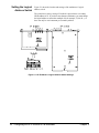
Setting the Logical Address Switch . . . . . . . . .
VXIbus Interrupt Lines . . . . . . . . . . . . . . . .
HP E1326B Internal Installation . . . . . . . . . . .
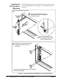
Installing the HP E1411B in a Mainframe . . . . . .
The Reference Frequency . . . . . . . . . . . . . . .
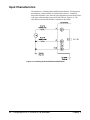
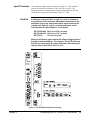
Input Characteristics . . . . . . . . . . . . . . . . . . . .
Input Terminals . . . . . . . . . . . . . . . . . . . .
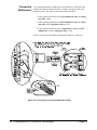
Connecting Multiplexers . . . . . . . . . . . . . . .
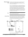
Connecting Input Signals . . . . . . . . . . . . . . . . .
Wiring Considerations . . . . . . . . . . . . . . . .
Measurement Connections . . . . . . . . . . . . . .
Carrier Cable Assemblies . . . . . . . . . . . . . . . . .
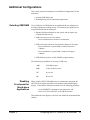
Additional Configurations . . . . . . . . . . . . . . . . .
Selecting VME RAM . . . . . . . . . . . . . . . . .
Disabling Front-panel for Stand-alone Applications .
.
.
.
.
.
.
.
.
.
.
.
.
.
.
.
.
.
.
.
.
.
.
.
.
.
.
.
.
.
.
.
.
.
.
.
.
.
.
.
.
.
.
.
.
.
.
.
.
.
.
.
.
.
.
.
.
.
.
.
.
.
.
.
.
.
.
.
.
.
.
.
.
.
.
.
.
.
.
.
.
.
.
.
.
.
.
.
.
.
.
.
.
.
.
.
.
.
.
.
.
.
.
.
.
.
.
.
.
.
.
.
.
.
.
.
.
.
.
.
.
.
.
.
.
.
.
.
.
.
.
.
.
.
.
.
.
. . . . . . . .
. . . . . . . .
. . . . . . . .
. . . . . . . .
. . . . . . . .
. . . . . . . .
. . . . . . . .
. . . . . . . .
. . . . . . . .
. . . . . . . .
. . . . . . . .
. . . . . . . .
. . . . . . . .
. . . . . . . .
. . . . . . . .
. . . . . . . .
. . . . . . . .
21
21
22
24
25
26
27
28
29
30
32
32
33
37
39
39
39
Chapter 3. Using the HP E1326B/E1411B Multimeter . . . . . . . . . . . . . . . . . . . . 41
About This Chapter . . . . . . . . . . . . . . . . . . .
Using the Programs . . . . . . . . . . . . . . . . .
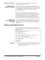
Making a Single Measurement . . . . . . . . . . . . .
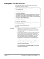
Making a Burst of Measurements . . . . . . . . . . . .
Making an Externally Triggered Burst of Measurements
HP E1326B/E1411B 5 1/2 Digit Multimeter User’s Manual
.
.
.
.
.
.
.
.
.
.
.
.
.
.
.
.
.
.
.
.
.
.
.
.
.
.
.
.
.
.
.
.
.
.
.
.
.
.
.
.
.
.
.
.
.
.
.
.
.
.
.
.
.
.
.
.
.
.
.
.
.
.
.
.
.
.
.
.
.
.
.
.
.
.
.
.
.
.
.
.
.
.
.
.
.
41
41
42
43
44
Contents
1
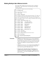
Making Multiple Burst Measurements . . . . . . . . . . . . . . . . . . . . . . . . . .
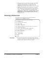
Scanning a Channel List . . . . . . . . . . . . . . . . . . . . . . . . . . . . . . . . . .
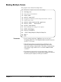
Making Multiple Scans . . . . . . . . . . . . . . . . . . . . . . . . . . . . . . . . . .
Making Multiple Paced Scans . . . . . . . . . . . . . . . . . . . . . . . . . . . . . . .
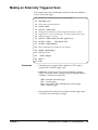
Making an Externally Triggered Scan . . . . . . . . . . . . . . . . . . . . . . . . . . .
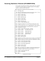
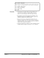
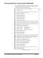
Scanning Switchbox Channels (E1326B/E1351A) . . . . . . . . . . . . . . . . . . . .
Scanning Switchbox Channels (E1411B/E1460A) . . . . . . . . . . . . . . . . . . . .
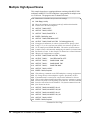
Multiple High-Speed Scans . . . . . . . . . . . . . . . . . . . . . . . . . . . . . . . .
Maximizing Measurement Speed . . . . . . . . . . . . . . . . . . . . . . . . . . . . .
Changing the Data Format . . . . . . . . . . . . . . . . . . . . . . . . . . . . . . . . .
Using a PC, C Language, and the HP 82335 HP-IB Interface Card . . . . . . . . . . .
Maximizing Measurement Accuracy . . . . . . . . . . . . . . . . . . . . . . . . . . .
Storing Readings in Shared Memory . . . . . . . . . . . . . . . . . . . . . . . . . . .
Checking for Errors . . . . . . . . . . . . . . . . . . . . . . . . . . . . . . . . . . . .
Synchronizing the Multimeter with a Computer . . . . . . . . . . . . . . . . . . . . .
Additional Measurement Functions . . . . . . . . . . . . . . . . . . . . . . . . . . . .
45
46
47
48
49
50
52
54
56
58
60
63
64
66
68
69
Chapter 4. Understanding the HP E1326B/E1411B Multimeter . . . . . . . . . . . . . . . 75
About This Chapter . . . . . . . . . . . . . .
Using MEASure and CONFigure Commands
How to Make Measurements . . . . . . . . .
Using MEASure . . . . . . . . . . . . .
Using CONFigure . . . . . . . . . . . . .
Data Formats and Destinations . . . . . . . .
Data Formats . . . . . . . . . . . . . . .
Reading Destinations . . . . . . . . . . .
Reading Destination Summary . . . . . .
Measurement Functions . . . . . . . . . . . .
DC Voltage Measurements . . . . . . . .
RMS AC Voltage Measurements . . . . .
Resistance Measurements . . . . . . . . .
Temperature Measurements . . . . . . .
Specifying a Function . . . . . . . . . . .
Multimeter Parameters . . . . . . . . . . . . .
Range . . . . . . . . . . . . . . . . . . .
Autorange . . . . . . . . . . . . . . . . .
Resolution . . . . . . . . . . . . . . . . .
Aperture and Integration Time . . . . . .
Autozero . . . . . . . . . . . . . . . . .
Offset Compensation . . . . . . . . . . .
Triggering the Multimeter . . . . . . . . . . .
The Trigger Source . . . . . . . . . . . .
The Trigger Count . . . . . . . . . . . .
The Trigger Delay . . . . . . . . . . . .
The Sample Count . . . . . . . . . . . .
The Sample Period . . . . . . . . . . . .
The Wait-For-Trigger State . . . . . . . .
Using a Single Trigger . . . . . . . . . .
Aborting a Measurement . . . . . . . . .
2
Contents
.
.
.
.
.
.
.
.
.
.
.
.
.
.
.
.
.
.
.
.
.
.
.
.
.
.
.
.
.
.
.
.
.
.
.
.
.
.
.
.
.
.
.
.
.
.
.
.
.
.
.
.
.
.
.
.
.
.
.
.
.
.
.
.
.
.
.
.
.
.
.
.
.
.
.
.
.
.
.
.
.
.
.
.
.
.
.
.
.
.
.
.
.
.
.
.
.
.
.
.
.
.
.
.
.
.
.
.
.
.
.
.
.
.
.
.
.
.
.
.
.
.
.
.
.
.
.
.
.
.
.
.
.
.
.
.
.
.
.
.
.
.
.
.
.
.
.
.
.
.
.
.
.
.
.
.
.
.
.
.
.
.
.
.
.
.
.
.
.
.
.
.
.
.
.
.
.
.
.
.
.
.
.
.
.
.
.
.
.
.
.
.
.
.
.
.
.
.
.
.
.
.
.
.
.
.
.
.
.
.
.
.
.
.
.
.
.
.
.
.
.
.
.
.
.
.
.
.
.
.
.
.
.
.
.
.
.
.
.
.
.
.
.
.
.
.
.
.
.
.
.
.
.
.
.
.
.
.
.
.
.
.
.
.
.
.
.
.
.
.
.
.
.
.
.
.
.
.
.
.
.
.
.
.
.
.
.
.
.
.
.
.
.
.
.
.
.
.
.
.
.
.
.
.
.
.
.
.
.
.
.
.
.
.
.
.
.
.
.
.
.
.
.
.
.
.
.
.
.
.
.
.
.
.
.
.
.
.
.
.
.
.
.
.
.
.
.
.
.
.
.
.
.
.
.
.
.
.
.
.
.
.
.
.
.
.
.
.
.
.
.
.
.
.
.
.
.
.
.
.
.
.
.
.
.
.
.
.
.
.
.
.
.
.
.
.
.
.
.
.
.
.
.
.
.
.
.
.
.
.
.
.
.
.
.
.
.
.
.
.
.
.
.
.
.
.
.
.
.
.
.
.
.
.
.
.
.
.
.
.
.
.
.
.
.
.
.
.
.
.
.
.
.
.
.
.
.
.
.
.
.
.
.
.
.
.
.
.
.
.
.
.
.
.
.
.
.
.
.
.
.
.
.
.
.
.
.
.
.
.
.
.
.
.
.
.
.
.
.
.
.
.
.
.
.
.
.
.
.
.
.
.
.
.
.
.
.
.
.
.
.
.
.
.
.
.
.
.
.
.
.
.
.
.
.
.
.
.
.
.
.
.
.
.
.
.
.
.
.
.
.
.
.
.
.
.
.
.
.
.
.
.
.
.
.
.
.
.
.
.
.
.
.
.
.
.
.
.
.
.
.
.
.
.
.
.
.
.
.
.
.
.
.
.
.
.
.
.
.
.
.
.
.
.
.
.
.
.
.
.
.
.
.
.
.
.
.
.
.
.
.
.
.
.
.
.
.
.
.
.
.
.
.
.
.
.
.
.
.
.
.
.
.
.
.
.
.
.
.
.
.
.
.
.
.
.
.
.
.
.
.
.
.
.
.
.
.
.
.
.
.
.
.
.
.
.
.
.
.
.
.
.
75
76
78
78
78
80
80
81
85
86
86
86
87
88
90
91
93
94
95
97
99
100
101
103
104
106
108
109
111
112
112
HP E1326B/E1411B 5 1/2 Digit Multimeter User’s Manual
Saving Multimeter Configurations . . . . . . . . . . . . . . . . . . . . . . . . . . . . 114
How to Save and Recall a Configuration . . . . . . . . . . . . . . . . . . . . . . . 114
Chapter 5. HP E1326B/E1411B Multimeter Command Reference . . . . . . . . . . . . . 117
Using This Chapter . . . . . . .
Command Types . . . . . . . . .
Common Command Format
SCPI Command Format . .
Linking Commands . . . . .
SCPI Command Reference . . .
ABORt . . . . . . . . . . . . . .
CALibration . . . . . . . . . . .
:LFRequency . . . . . . . .
:LFRequency? . . . . . . . .
:ZERO:AUTO . . . . . . .
:ZERO:AUTO? . . . . . . .
CONFigure . . . . . . . . . . . .
:FRESistance . . . . . . . .
:RESistance . . . . . . . . .
:TEMPerature . . . . . . . .
:VOLTage:AC . . . . . . .
:VOLTage[:DC] . . . . . .
CONFigure? . . . . . . . . . . .
DIAGnostic . . . . . . . . . . .
:FETS . . . . . . . . . . . .
:FETS? . . . . . . . . . . .
DISPlay . . . . . . . . . . . . .
:MONitor:CHANnel . . . .
:MONitor:CHANnel? . . . .
:MONitor[:STATe] . . . . .
:MONitor[:STATe]? . . . .
FETCh? . . . . . . . . . . . . .
FORMat . . . . . . . . . . . . .
[:DATA] . . . . . . . . . .
FORMat? . . . . . . . . . . . . .
INITiate . . . . . . . . . . . . .
[:IMMediate] . . . . . . . .
MEASure . . . . . . . . . . . .
:FRESistance? . . . . . . . .
:RESistance? . . . . . . . .
:TEMPerature? . . . . . . .
:VOLTage:AC? . . . . . . .
:VOLTage[:DC]? . . . . . .
MEMory . . . . . . . . . . . . .
:VME:ADDRess . . . . . .
:VME:ADDRess? . . . . . .
:VME:SIZE . . . . . . . . .
:VME:SIZE? . . . . . . . .
.
.
.
.
.
.
.
.
.
.
.
.
.
.
.
.
.
.
.
.
.
.
.
.
.
.
.
.
.
.
.
.
.
.
.
.
.
.
.
.
.
.
.
.
.
.
.
.
.
.
.
.
.
.
.
.
.
.
.
.
.
.
.
.
.
.
.
.
.
.
.
.
.
.
.
.
.
.
.
.
.
.
.
.
.
.
.
.
.
.
.
.
.
.
.
.
.
.
.
.
.
.
.
.
.
.
.
.
.
.
.
.
.
.
.
.
.
.
.
.
.
.
.
.
.
.
.
.
.
.
.
.
.
.
.
.
.
.
.
.
.
.
.
.
.
.
.
.
.
.
.
.
.
.
.
.
.
.
.
.
.
.
.
.
.
.
.
.
.
.
.
.
.
.
.
.
HP E1326B/E1411B 5 1/2 Digit Multimeter User’s Manual
.
.
.
.
.
.
.
.
.
.
.
.
.
.
.
.
.
.
.
.
.
.
.
.
.
.
.
.
.
.
.
.
.
.
.
.
.
.
.
.
.
.
.
.
.
.
.
.
.
.
.
.
.
.
.
.
.
.
.
.
.
.
.
.
.
.
.
.
.
.
.
.
.
.
.
.
.
.
.
.
.
.
.
.
.
.
.
.
.
.
.
.
.
.
.
.
.
.
.
.
.
.
.
.
.
.
.
.
.
.
.
.
.
.
.
.
.
.
.
.
.
.
.
.
.
.
.
.
.
.
.
.
.
.
.
.
.
.
.
.
.
.
.
.
.
.
.
.
.
.
.
.
.
.
.
.
.
.
.
.
.
.
.
.
.
.
.
.
.
.
.
.
.
.
.
.
.
.
.
.
.
.
.
.
.
.
.
.
.
.
.
.
.
.
.
.
.
.
.
.
.
.
.
.
.
.
.
.
.
.
.
.
.
.
.
.
.
.
.
.
.
.
.
.
.
.
.
.
.
.
.
.
.
.
.
.
.
.
.
.
.
.
.
.
.
.
.
.
.
.
.
.
.
.
.
.
.
.
.
.
.
.
.
.
.
.
.
.
.
.
.
.
.
.
.
.
.
.
.
.
.
.
.
.
.
.
.
.
.
.
.
.
.
.
.
.
.
.
.
.
.
.
.
.
.
.
.
.
.
.
.
.
.
.
.
.
.
.
.
.
.
.
.
.
.
.
.
.
.
.
.
.
.
.
.
.
.
.
.
.
.
.
.
.
.
.
.
.
.
.
.
.
.
.
.
.
.
.
.
.
.
.
.
.
.
.
.
.
.
.
.
.
.
.
.
.
.
.
.
.
.
.
.
.
.
.
.
.
.
.
.
.
.
.
.
.
.
.
.
.
.
.
.
.
.
.
.
.
.
.
.
.
.
.
.
.
.
.
.
.
.
.
.
.
.
.
.
.
.
.
.
.
.
.
.
.
.
.
.
.
.
.
.
.
.
.
.
.
.
.
.
.
.
.
.
.
.
.
.
.
.
.
.
.
.
.
.
.
.
.
.
.
.
.
.
.
.
.
.
.
.
.
.
.
.
.
.
.
.
.
.
.
.
.
.
.
.
.
.
.
.
.
.
.
.
.
.
.
.
.
.
.
.
.
.
.
.
.
.
.
.
.
.
.
.
.
.
.
.
.
.
.
.
.
.
.
.
.
.
.
.
.
.
.
.
.
.
.
.
.
.
.
.
.
.
.
.
.
.
.
.
.
.
.
.
.
.
.
.
.
.
.
.
.
.
.
.
.
.
.
.
.
.
.
.
.
.
.
.
.
.
.
.
.
.
.
.
.
.
.
.
.
.
.
.
.
.
.
.
.
.
.
.
.
.
.
.
.
.
.
.
.
.
.
.
.
.
.
.
.
.
.
.
.
.
.
.
.
.
.
.
.
.
.
.
.
.
.
.
.
.
.
.
.
.
.
.
.
.
.
.
.
.
.
.
.
.
.
.
.
.
.
.
.
.
.
.
.
.
.
.
.
.
.
.
.
.
.
.
.
.
.
.
.
.
.
.
.
.
.
.
.
.
.
.
.
.
.
.
.
.
.
.
.
.
.
.
.
.
.
.
.
.
.
.
.
.
.
.
.
.
.
.
.
.
.
.
.
.
.
.
.
.
.
.
.
.
.
.
.
.
.
.
.
.
.
.
.
.
.
.
.
.
.
.
.
.
.
.
.
.
.
.
.
.
.
.
.
.
.
.
.
.
.
.
.
.
.
.
.
.
.
.
.
.
.
.
.
.
.
.
.
.
.
.
.
.
.
.
.
.
.
.
.
.
.
.
.
.
.
.
.
.
.
.
.
.
.
.
.
.
.
.
.
.
.
.
.
.
.
.
.
.
.
.
.
.
.
.
.
.
.
.
.
.
.
.
.
.
.
.
.
.
.
.
.
.
.
.
.
.
.
.
.
.
.
.
.
.
.
.
.
.
.
.
.
.
.
.
.
.
.
.
.
.
.
.
.
.
.
.
.
.
.
.
.
.
.
.
.
.
.
.
.
.
.
.
.
.
.
.
.
.
.
.
.
.
.
.
.
.
.
.
.
.
.
.
.
.
.
.
.
.
.
.
.
.
.
.
.
.
.
.
.
.
.
.
.
.
.
.
.
.
.
.
.
.
.
.
.
.
.
.
.
.
.
.
.
.
.
.
.
.
.
.
.
.
.
.
.
.
.
.
.
.
.
.
.
.
.
.
.
.
.
.
.
.
.
.
.
.
.
.
.
.
.
.
.
.
.
.
.
.
.
.
.
.
.
.
.
.
.
.
.
.
.
.
.
.
.
.
.
.
.
.
.
.
.
.
.
.
.
.
.
.
.
.
.
.
.
.
.
.
.
.
.
.
.
.
.
.
.
.
.
.
.
.
.
.
.
.
.
.
.
.
.
.
.
.
.
.
.
.
.
.
.
.
.
.
.
117
117
117
117
119
121
122
123
123
123
124
124
126
127
128
129
130
132
134
135
135
135
136
136
137
137
138
139
140
140
141
142
142
143
144
145
146
147
148
150
150
150
151
151
Contents
3
:VME:STATe . . . . . . . . . . . . . . . . . . . . . . . . . . . . . . . . . . . . . 152
:VME:STATe? . . . . . . . . . . . . . . . . . . . . . . . . . . . . . . . . . . . . 152
OUTPut . . . . . . . . . . . . . . . . . . . . . . . . . . . . . . . . . . . . . . . . . . 153
n
:TTLTrg [:STATe] . . . . . . . . . . . . . . . . . . . . . . . . . . . . . . . . . 153
:TTLTrgn[:STATe]? . . . . .
READ? . . . . . . . . . . . . . . .
SAMPle . . . . . . . . . . . . . .
:COUNt . . . . . . . . . . . .
:COUNt? . . . . . . . . . . .
:SOURce . . . . . . . . . . .
:SOURce? . . . . . . . . . . .
:TIMer . . . . . . . . . . . . .
:TIMer? . . . . . . . . . . . .
[SENSe:] . . . . . . . . . . . . . .
FUNCtion . . . . . . . . . . .
FUNCtion? . . . . . . . . . .
RESistance:APERture . . . .
RESistance:APERture? . . . .
RESistance:NPLC . . . . . .
RESistance:NPLC? . . . . . .
RESistance:OCOMpensated .
RESistance: OCOMpensated?
RESistance:RANGe . . . . .
RESistance:RANGe? . . . . .
RESistance:RANGe :AUTO .
RESistance:RANGe:AUTO? .
RESistance:RESolution . . . .
RESistance:RESolution? . . .
VOLTage:AC:RANGe . . . .
VOLTage:AC: RANGe? . . .
VOLTage:APERture . . . . .
VOLTage:APERture? . . . .
VOLTage[:DC]:RANGe . . .
VOLTage[:DC]:RANGe? . .
VOLTage:NPLC . . . . . . .
VOLTage:NPLC? . . . . . . .
VOLTage:RANGe:AUTO . .
VOLTage:RANGe:AUTO? .
VOLTage:RESolution . . . .
VOLTage:RESolution? . . . .
SYSTem . . . . . . . . . . . . . .
:CDEScription? . . . . . . . .
:CTYPe? . . . . . . . . . . .
:ERRor? . . . . . . . . . . . .
TRIGger . . . . . . . . . . . . . .
:COUNt . . . . . . . . . . . .
4
Contents
.
.
.
.
.
.
.
.
.
.
.
.
.
.
.
.
.
.
.
.
.
.
.
.
.
.
.
.
.
.
.
.
.
.
.
.
.
.
.
.
.
.
.
.
.
.
.
.
.
.
.
.
.
.
.
.
.
.
.
.
.
.
.
.
.
.
.
.
.
.
.
.
.
.
.
.
.
.
.
.
.
.
.
.
.
.
.
.
.
.
.
.
.
.
.
.
.
.
.
.
.
.
.
.
.
.
.
.
.
.
.
.
.
.
.
.
.
.
.
.
.
.
.
.
.
.
.
.
.
.
.
.
.
.
.
.
.
.
.
.
.
.
.
.
.
.
.
.
.
.
.
.
.
.
.
.
.
.
.
.
.
.
.
.
.
.
.
.
.
.
.
.
.
.
.
.
.
.
.
.
.
.
.
.
.
.
.
.
.
.
.
.
.
.
.
.
.
.
.
.
.
.
.
.
.
.
.
.
.
.
.
.
.
.
.
.
.
.
.
.
.
.
.
.
.
.
.
.
.
.
.
.
.
.
.
.
.
.
.
.
.
.
.
.
.
.
.
.
.
.
.
.
.
.
.
.
.
.
.
.
.
.
.
.
.
.
.
.
.
.
.
.
.
.
.
.
.
.
.
.
.
.
.
.
.
.
.
.
.
.
.
.
.
.
.
.
.
.
.
.
.
.
.
.
.
.
.
.
.
.
.
.
.
.
.
.
.
.
.
.
.
.
.
.
.
.
.
.
.
.
.
.
.
.
.
.
.
.
.
.
.
.
.
.
.
.
.
.
.
.
.
.
.
.
.
.
.
.
.
.
.
.
.
.
.
.
.
.
.
.
.
.
.
.
.
.
.
.
.
.
.
.
.
.
.
.
.
.
.
.
.
.
.
.
.
.
.
.
.
.
.
.
.
.
.
.
.
.
.
.
.
.
.
.
.
.
.
.
.
.
.
.
.
.
.
.
.
.
.
.
.
.
.
.
.
.
.
.
.
.
.
.
.
.
.
.
.
.
.
.
.
.
.
.
.
.
.
.
.
.
.
.
.
.
.
.
.
.
.
.
.
.
.
.
.
.
.
.
.
.
.
.
.
.
.
.
.
.
.
.
.
.
.
.
.
.
.
.
.
.
.
.
.
.
.
.
.
.
.
.
.
.
.
.
.
.
.
.
.
.
.
.
.
.
.
.
.
.
.
.
.
.
.
.
.
.
.
.
.
.
.
.
.
.
.
.
.
.
.
.
.
.
.
.
.
.
.
.
.
.
.
.
.
.
.
.
.
.
.
.
.
.
.
.
.
.
.
.
.
.
.
.
.
.
.
.
.
.
.
.
.
.
.
.
.
.
.
.
.
.
.
.
.
.
.
.
.
.
.
.
.
.
.
.
.
.
.
.
.
.
.
.
.
.
.
.
.
.
.
.
.
.
.
.
.
.
.
.
.
.
.
.
.
.
.
.
.
.
.
.
.
.
.
.
.
.
.
.
.
.
.
.
.
.
.
.
.
.
.
.
.
.
.
.
.
.
.
.
.
.
.
.
.
.
.
.
.
.
.
.
.
.
.
.
.
.
.
.
.
.
.
.
.
.
.
.
.
.
.
.
.
.
.
.
.
.
.
.
.
.
.
.
.
.
.
.
.
.
.
.
.
.
.
.
.
.
.
.
.
.
.
.
.
.
.
.
.
.
.
.
.
.
.
.
.
.
.
.
.
.
.
.
.
.
.
.
.
.
.
.
.
.
.
.
.
.
.
.
.
.
.
.
.
.
.
.
.
.
.
.
.
.
.
.
.
.
.
.
.
.
.
.
.
.
.
.
.
.
.
.
.
.
.
.
.
.
.
.
.
.
.
.
.
.
.
.
.
.
.
.
.
.
.
.
.
.
.
.
.
.
.
.
.
.
.
.
.
.
.
.
.
.
.
.
.
.
.
.
.
.
.
.
.
.
.
.
.
.
.
.
.
.
.
.
.
.
.
.
.
.
.
.
.
.
.
.
.
.
.
.
.
.
.
.
.
.
.
.
.
.
.
.
.
.
.
.
.
.
.
.
.
.
.
.
.
.
.
.
.
.
.
.
.
.
.
.
.
.
.
.
.
.
.
.
.
.
.
.
.
.
.
.
.
.
.
.
.
.
.
.
.
.
.
.
.
.
.
.
.
.
.
.
.
.
.
.
.
.
.
.
.
.
.
.
.
.
.
.
.
.
.
.
.
.
.
.
.
.
.
.
.
.
.
.
.
.
.
.
.
.
.
.
.
.
.
.
.
.
.
.
.
.
.
.
.
.
.
.
.
.
.
.
.
.
.
.
.
.
.
.
.
.
.
.
.
.
.
.
.
.
.
.
.
.
.
.
.
.
.
.
.
.
.
.
.
.
.
.
.
.
.
.
.
.
.
.
.
.
.
.
.
.
.
.
.
.
.
.
.
.
.
.
.
.
.
.
.
.
.
.
.
.
.
.
.
.
.
.
.
.
.
.
.
.
.
.
.
.
.
.
.
.
.
.
.
.
.
.
.
.
.
.
.
.
.
.
.
.
.
.
.
.
.
.
.
.
.
.
.
.
.
.
.
.
.
.
.
.
.
.
.
.
.
.
.
.
.
.
.
.
.
.
.
.
.
.
.
.
.
.
.
.
.
.
.
.
154
155
157
157
158
158
159
159
160
161
162
162
163
164
164
165
165
165
166
167
167
168
168
169
169
170
171
171
172
173
173
174
174
175
175
176
177
177
177
178
179
179
HP E1326B/E1411B 5 1/2 Digit Multimeter User’s Manual
:COUNt? . . . . . . . . . . . . . . . .
:DELay . . . . . . . . . . . . . . . . .
:DELay? . . . . . . . . . . . . . . . . .
:DELay:AUTO . . . . . . . . . . . . .
:DELay:AUTO? . . . . . . . . . . . .
[:IMMediate] . . . . . . . . . . . . . .
:SOURce . . . . . . . . . . . . . . . .
:SOURce? . . . . . . . . . . . . . . . .
IEEE 488.2 Common Command Reference
Command Quick Reference . . . . . . . . .
.
.
.
.
.
.
.
.
.
.
.
.
.
.
.
.
.
.
.
.
.
.
.
.
.
.
.
.
.
.
.
.
.
.
.
.
.
.
.
.
.
.
.
.
.
.
.
.
.
.
.
.
.
.
.
.
.
.
.
.
.
.
.
.
.
.
.
.
.
.
.
.
.
.
.
.
.
.
.
.
.
.
.
.
.
.
.
.
.
.
.
.
.
.
.
.
.
.
.
.
.
.
.
.
.
.
.
.
.
.
.
.
.
.
.
.
.
.
.
.
.
.
.
.
.
.
.
.
.
.
.
.
.
.
.
.
.
.
.
.
.
.
.
.
.
.
.
.
.
.
.
.
.
.
.
.
.
.
.
.
.
.
.
.
.
.
.
.
.
.
.
.
.
.
.
.
.
.
.
.
.
.
.
.
.
.
.
.
.
.
.
.
.
.
.
.
.
.
.
.
.
.
.
.
.
.
.
.
.
.
.
.
.
.
.
.
.
.
.
.
.
.
.
.
.
.
.
.
.
.
180
181
181
182
182
183
183
184
186
187
Appendix A. HP E1326B/E1411B Multimeter Specifications . . . . . . . . . . . . . . . . 189
General Specifications . . . . . . . . . . . . . . . . . . . . . . . . . . . . . . . . . . . 189
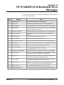
Appendix B. HP E1326B/E1411B Multimeter Error Messages . . . . . . . . . . . . . . . 197
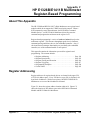
Appendix C. HP E1326B/E1411B Multimeter Register-Based Programming . . . . . . . 199
About This Appendix . . . . . . . . . . . . . . . . . . . . . . . . . . . . . . . . . . .
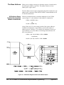
Register Addressing . . . . . . . . . . . . . . . . . . . . . . . . . . . . . . . . . . . .
The Base Address . . . . . . . . . . . . . . . . . . . . . . . . . . . . . . . . . . .
Register Offset . . . . . . . . . . . . . . . . . . . . . . . . . . . . . . . . . . . .
Accessing the Registers . . . . . . . . . . . . . . . . . . . . . . . . . . . . . . . .
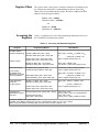
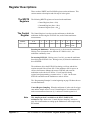
Register Descriptions . . . . . . . . . . . . . . . . . . . . . . . . . . . . . . . . . . .
The WRITE Registers . . . . . . . . . . . . . . . . . . . . . . . . . . . . . . . .
The Control Register . . . . . . . . . . . . . . . . . . . . . . . . . . . . . . . . .
The Command and Parameter Registers . . . . . . . . . . . . . . . . . . . . . . .
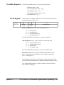
The READ Registers . . . . . . . . . . . . . . . . . . . . . . . . . . . . . . . . .
The ID Register . . . . . . . . . . . . . . . . . . . . . . . . . . . . . . . . . . . .
The Device Type Register . . . . . . . . . . . . . . . . . . . . . . . . . . . . . .
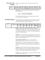
The Status Register . . . . . . . . . . . . . . . . . . . . . . . . . . . . . . . . . .
The Query Response Register . . . . . . . . . . . . . . . . . . . . . . . . . . . .
The Data Buffer . . . . . . . . . . . . . . . . . . . . . . . . . . . . . . . . . . . .
Program Timing and Execution . . . . . . . . . . . . . . . . . . . . . . . . . . . . . .
Resetting the Multimeter . . . . . . . . . . . . . . . . . . . . . . . . . . . . . . .
Configuring the Multimeter . . . . . . . . . . . . . . . . . . . . . . . . . . . . .
Retrieving Measurements . . . . . . . . . . . . . . . . . . . . . . . . . . . . . . .
Checking for Errors . . . . . . . . . . . . . . . . . . . . . . . . . . . . . . . . . .
Querying Parameters . . . . . . . . . . . . . . . . . . . . . . . . . . . . . . . . .
Using a Multiplexer with the Multimeter . . . . . . . . . . . . . . . . . . . . . . .
Register Triggering . . . . . . . . . . . . . . . . . . . . . . . . . . . . . . . . . . . .
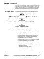
The Trigger System . . . . . . . . . . . . . . . . . . . . . . . . . . . . . . . . . .
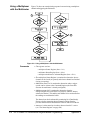
Multimeter Triggering Model . . . . . . . . . . . . . . . . . . . . . . . . . . . .
Control Register Sampling . . . . . . . . . . . . . . . . . . . . . . . . . . . . . .
Programming Examples . . . . . . . . . . . . . . . . . . . . . . . . . . . . . . . . . .
System Configuration . . . . . . . . . . . . . . . . . . . . . . . . . . . . . . . . .
Resetting the Multimeter . . . . . . . . . . . . . . . . . . . . . . . . . . . . . .
Reading the ID Register . . . . . . . . . . . . . . . . . . . . . . . . . . . . . . .
HP E1326B/E1411B 5 1/2 Digit Multimeter User’s Manual
199
199
200
202
202
203
203
203
204
205
205
206
206
207
208
210
210
211
213
214
215
216
217
217
218
219
220
220
221
223
Contents
5
Reading the Device Type Register . . . .
Reading the Query Response Register . .
Reading an Error Code . . . . . . . . . .
Stand-Alone Multimeter Measurements .
Scanning Multimeter Measurements . . .
Useful Tables . . . . . . . . . . . . . . . . .
Command and Parameter Opcodes . . . .
Register-Based Programming Error Codes
Multimeter Power-On Settings . . . . . .
Function and Aperture Change Times . .
VME Interrupts . . . . . . . . . . . . . .
.
.
.
.
.
.
.
.
.
.
.
.
.
.
.
.
.
.
.
.
.
.
.
.
.
.
.
.
.
.
.
.
.
.
.
.
.
.
.
.
.
.
.
.
.
.
.
.
.
.
.
.
.
.
.
.
.
.
.
.
.
.
.
.
.
.
.
.
.
.
.
.
.
.
.
.
.
.
.
.
.
.
.
.
.
.
.
.
.
.
.
.
.
.
.
.
.
.
.
.
.
.
.
.
.
.
.
.
.
.
. .
. .
. .
. .
. .
. .
. .
. .
. .
. .
. .
. . . . . . . . . .
. . . . . . . . . .
. . . . . . . . . .
. . . . . . . . . .
. . . . . . . . . .
. . . . . . . . . .
. . . . . . . . . .
. . . . . . . . . .
. . . . . . . . . .
. . . . . . . . . .
. . . . . . . . . .
224
226
230
234
246
262
262
264
265
266
267
Appendix D. Measurement Speed and Accuracy Tradeoffs . . . . . . . . . . . . . . . . . 269
Index . . . . . . . . . . . . . . . . . . . . . . . . . . . . . . . . . . . . . . . . . . . . . . . . 279
6
Contents
HP E1326B/E1411B 5 1/2 Digit Multimeter User’s Manual
Certification
Hewlett-Packard Company certifies that this product met its published specifications at the time of shipment from the factory. HewlettPackard further certifies that its calibration measurements are traceable to the United States National Institute of Standards and Technology (formerly National Bureau of Standards), to the extent allowed by that organization’s calibration facility, and to the calibration
facilities of other International Standards Organization members.
Warranty
This Hewlett-Packard product is warranted against defects in materials and workmanship for a period of three years from date of shipment. Duration and conditions of warranty for this product may be superseded when the product is integrated into (becomes a part of)
other HP products. During the warranty period, Hewlett-Packard Company will, at its option, either repair or replace products which
prove to be defective.
For warranty service or repair, this product must be returned to a service facility designated by Hewlett-Packard (HP). Buyer shall prepay shipping charges to HP and HP shall pay shipping charges to return the product to Buyer. However, Buyer shall pay all shipping
charges, duties, and taxes for products returned to HP from another country.
HP warrants that its software and firmware designated by HP for use with a product will execute its programming instructions when
properly installed on that product. HP does not warrant that the operation of the product, or software, or firmware will be uninterrupted
or error free.
Limitation Of Warranty
The foregoing warranty shall not apply to defects resulting from improper or inadequate maintenance by Buyer, Buyer-supplied products or interfacing, unauthorized modification or misuse, operation outside of the environmental specifications for the product, or improper site preparation or maintenance.
The design and implementation of any circuit on this product is the sole responsibility of the Buyer. HP does not warrant the Buyer’s
circuitry or malfunctions of HP products that result from the Buyer’s circuitry. In addition, HP does not warrant any damage that occurs as a result of the Buyer’s circuit or any defects that result from Buyer-supplied products.
NO OTHER WARRANTY IS EXPRESSED OR IMPLIED. HP SPECIFICALLY DISCLAIMS THE IMPLIED WARRANTIES OF
MERCHANTABILITY AND FITNESS FOR A PARTICULAR PURPOSE.
Exclusive Remedies
THE REMEDIES PROVIDED HEREIN ARE BUYER’S SOLE AND EXCLUSIVE REMEDIES. HP SHALL NOT BE LIABLE
FOR ANY DIRECT, INDIRECT, SPECIAL, INCIDENTAL, OR CONSEQUENTIAL DAMAGES, WHETHER BASED ON CONTRACT, TORT, OR ANY OTHER LEGAL THEORY.
Notice
The information contained in this document is subject to change without notice. HEWLETT-PACKARD (HP) MAKES NO WARRANTY OF ANY KIND WITH REGARD TO THIS MATERIAL, INCLUDING, BUT NOT LIMITED TO, THE IMPLIED WARRANTIES OF MERCHANTABILITY AND FITNESS FOR A PARTICULAR PURPOSE. HP shall not be liable for errors contained
herein or for incidental or consequential damages in connection with the furnishing, performance or use of this material. This document contains proprietary information which is protected by copyright. All rights are reserved. No part of this document may be photocopied, reproduced, or translated to another language without the prior written consent of Hewlett-Packard Company. HP assumes no
responsibility for the use or reliability of its software on equipment that is not furnished by HP.
U.S. Government Restricted Rights
The Software and Documentation have been developed entirely at private expense. They are delivered and licensed as "commercial
computer software" as defined in DFARS 252.227-7013 (October 1988), DFARS 252.211.7015 (May 1991) or DFARS 252.227-7014
(June 1995), as a "commercial item" as defined in FAR 2.101(a), or as "Restricted computer software" as defined in FAR 52.227-19
(June 1987) (or any equivalent agency regulation or contract clause), whichever is applicable. You have only those rights provided for
such Software and Documentation by the applicable FAR or DFARS clause or the HP standard software agreement for the product involved.
E1326B/E1411B 5 1/2-Digit Multimeter User’s Manual
E1326-90009
Copyright © 2004 Agilent Technologies, All Rights Reserved.
HP E1326B/E1411B 5 1/2-Digit Multimeter User’s Manual
7
Documentation History
All Editions and Updates of this manual and their creation date are listed below. The first Edition of the manual is Edition 1. The Edition number increments by 1 whenever the manual is revised. Updates, which are issued between Editions, contain replacement pages
to correct or add additional information to the current Edition of the manual. Whenever a new Edition is created, it will contain all of
the Update information for the previous Edition. Each new Edition or Update also includes a revised copy of this documentation history page.
Edition 1, August 2004;
Safety Symbols
Instruction manual symbol affixed to product. Indicates that the user must refer to the
manual for specific WARNING or CAUTION information to avoid personal injury
or damage to the product.
Alternating current (AC).
Direct current (DC).
Indicates hazardous voltages.
Indicates the field wiring terminal that must
be connected to earth ground before operating the equipment—protects against electrical shock in case of fault.
or
Frame or chassis ground terminal—typically connects to the equipment’s metal
frame.
WARNING
Calls attention to a procedure, practice, or
condition that could cause bodily injury or
death.
CAUTION
Calls attention to a procedure, practice, or condition that could possibly cause damage to
equipment or permanent loss of data.
WARNINGS
The following general safety precautions must be observed during all phases of operation, service, and repair of this product.
Failure to comply with these precautions or with specific warnings elsewhere in this manual violates safety standards of design,
manufacture, and intended use of the product. Hewlett-Packard Company assumes no liability for the customer’s failure to
comply with these requirements.
Ground the equipment: For Safety Class 1 equipment (equipment having a protective earth terminal), an uninterruptible safety earth
ground must be provided from the mains power source to the product input wiring terminals or supplied power cable.
DO NOT operate the product in an explosive atmosphere or in the presence of flammable gases or fumes.
For continued protection against fire, replace the line fuse(s) only with fuse(s) of the same voltage and current rating and type.
DO NOT use repaired fuses or short-circuited fuse holders.
Keep away from live circuits: Operating personnel must not remove equipment covers or shields. Procedures involving the removal
of covers or shields are for use by service-trained personnel only. Under certain conditions, dangerous voltages may exist even with the
equipment switched off. To avoid dangerous electrical shock, DO NOT perform procedures involving cover or shield removal unless
you are qualified to do so.
DO NOT operate damaged equipment: Whenever it is possible that the safety protection features built into this product have been impaired, either through physical damage, excessive moisture, or any other reason, REMOVE POWER and do not use the product until
safe operation can be verified by service-trained personnel. If necessary, return the product to a Hewlett-Packard Sales and Service Office for service and repair to ensure that safety features are maintained.
DO NOT service or adjust alone: Do not attempt internal service or adjustment unless another person, capable of rendering first aid
and resuscitation, is present.
DO NOT substitute parts or modify equipment: Because of the danger of introducing additional hazards, do not install substitute
parts or perform any unauthorized modification to the product. Return the product to a Hewlett-Packard Sales and Service Office for
service and repair to ensure that safety features are maintained.
8
HP E1326B/E1411B 5 1/2-Digit Multimeter User’s Manual
DECLARATION OF CONFORMITY
SA
According to ISO/IEC Guide 22 and CEN/CENELEC EN 45014
Manufacturer’s Name:
Manufacturer’s Address:
Agilent Technologies, Incorporated
Measurement Product Generation Unit
th
815 14 ST. S.W.
Loveland, CO 80537 USA
Declares, that the product
Product Name:
Model Number:
Product Options:
B-Size VXI 5 ½ Digital Multimeter
E1326B
This declaration covers all options of the above product(s).
Conforms with the following European Directives:
The product herewith complies with the requirements of the Low Voltage Directive 73/23/EEC and the EMC Directive 89/336/EEC
and carries the CE Marking accordingly
Conforms with the following product standards:
EMC
Standard
Limit
IEC 61326-1:1997+A1:1998 / EN 61326-1:1997+A1:1998
CISPR 11:1997 +A1:1997 / EN 55011:1998
IEC 61000-4-2:1995+A1:1998 / EN 61000-4-2:1995
IEC 61000-4-3:1995 / EN 61000-4-3:1995
IEC 61000-4-4:1995 / EN 61000-4-4:1995
IEC 61000-4-5:1995 / EN 61000-4-5:1995
IEC 61000-4-6:1996 / EN 61000-4-6:1996
IEC 61000-4-11:1994 / EN 61000-4-11:1994
Group 1 Class A [1]
4kV CD, 8kV AD
3 V/m, 80-1000 MHz
0.5kV signal lines, 1kV power lines
0.5 kV line-line, 1 kV line-ground
3V, 0.15-80 MHz
I cycle, 100%
Canada: ICES-001:1998
Australia/New Zealand: AS/NZS 2064.1
Safety
IEC 61010-1:1990+A1:1992+A2:1995 / EN 61010-1:1993+A2:1995
Canada: CSA C22.2 No. 1010.1:1992
UL 3111-1:1994
Supplemental Information:
[1]
The product was tested in a typical configuration with Agilent Technologies test systems.
September 5, 2000
Date
Name
Quality Manager
Title
For further information, please contact your local Agilent Technologies sales office, agent or distributor.
Authorized EU-representative: Agilent Technologies Deutschland GmbH, Herrenberger Straβe 130, D 71034 Böblingen, Germany
Revision: A.03
Issue Date: 09/05/00
DECLARATION OF CONFORMITY
SA
According to ISO/IEC Guide 22 and CEN/CENELEC EN 45014
Manufacturer’s Name:
Manufacturer’s Address:
Agilent Technologies, Incorporated
Measurement Product Generation Unit
th
815 14 ST. S.W.
Loveland, CO 80537 USA
Declares, that the product
Product Name:
Model Number:
Product Options:
5 ½ Digit Multimeter
E1411B
This declaration covers all options of the above product(s).
Conforms with the following European Directives:
The product herewith complies with the requirements of the Low Voltage Directive 73/23/EEC and the EMC Directive 89/336/EEC
and carries the CE Marking accordingly
Conforms with the following product standards:
EMC
Standard
Limit
IEC 61326-1:1997+A1:1998 / EN 61326-1:1997+A1:1998
CISPR 11:1997 +A1:1997 / EN 55011:1998
IEC 61000-4-2:1995+A1:1998 / EN 61000-4-2:1995
IEC 61000-4-3:1995 / EN 61000-4-3:1995
IEC 61000-4-4:1995 / EN 61000-4-4:1995
IEC 61000-4-5:1995 / EN 61000-4-5:1995
IEC 61000-4-6:1996 / EN 61000-4-6:1996
IEC 61000-4-11:1994 / EN 61000-4-11:1994
Group 1 Class A [1]
4kV CD, 8kV AD
3 V/m, 80-1000 MHz
0.5kV signal lines, 1kV power lines
0.5 kV line-line, 1 kV line-ground
3V, 0.15-80 MHz
I cycle, 100%
Canada: ICES-001:1998
Australia/New Zealand: AS/NZS 2064.1
Safety
IEC 61010-1:1990+A1:1992+A2:1995 / EN 61010-1:1993+A2:1995
Canada: CSA C22.2 No. 1010.1:1992
UL 3111-1:1994
Supplemental Information:
[1]
The product was tested in a typical configuration with Agilent Technologies test systems.
September 5, 2000
Date
Name
Quality Manager
Title
For further information, please contact your local Agilent Technologies sales office, agent or distributor.
Authorized EU-representative: Agilent Technologies Deutschland GmbH, Herrenberger Straβe 130, D 71034 Böblingen, Germany
Revision: A.03
Issue Date: 09/05/00
Chapter 1
Getting Started with the HP E1326B/E1411B
Multimeter
About This Chapter
This chapter introduces you the B-size HP E1326B and C-size HP E1411B
51⁄2 - Digit Multimeters. The main sections of the chapter are:
• Multimeter Overview. . . . . . . . . . . . . . . . . . . . . . . . . . . . . . . Page 13
• Introduction to Operation. . . . . . . . . . . . . . . . . . . . . . . . . . . . Page 16
Note
This manual is to be used with the HP E1326B or HP E1411B installed in
the HP 75000 Series B or Series C mainframe, and when the multimeter is
programmed using Standard Commands for Programmable Instruments
(SCPI) language or when it is programmed at the register level.
Multimeter Overview
The HP E1326B/E1411B multimeter is a register-based VXI instrument.
There are two different methods of programming the multimeter based on
the system configuration that it is used in.
If the HP E1326B is used in an HP E1300/E1301/E1302 B-size VXI
mainframe, or if the HP E1326B/E1411B is used in a C-size VXI
mainframe with an HP E1405/E1406 Command Module or with a computer
which has HP Compiled SCPI software, then it may be programmed using
SCPI language. This is the method described in Chapters 1 through 5.
If the HP E1326B is in a VME mainframe or the E1326B/E1411B is in a
C-size VXI mainframe and no HP Command Module or computer with
Compiled SCPI is present, then the multimeter must be programmed at the
register level. Appendix C covers register level programming.
The HP SCPI driver provides an error queue, input and output buffers,
status registers, and is allocated a portion of mainframe memory for reading
storage. This "instrument" may consist of the multimeter, or it can also
include multiplexers such as the HP E1345A/46A/47A/51A/53A and the
HP E1460A/76A. The instrument is operated from the mainframe front
panel or from a computer using the SCPI language.
Instruments are based on the logical addresses of the plug-in modules. The
HP VXIbus Systems Installation and Getting Started Guide explains how to
Chapter 1
Getting Started with the HP E1326B/E1411B Multimeter
13
set the addresses in order to create an instrument. The guide should be your
starting point toward using the multimeter. The functions and features of
the multimeter are presented in the following functional, electrical, and
physical descriptions.
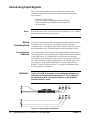
Functional
Description
The 51⁄2 - digit multimeter can be used stand-alone, or combined with
multiplexers (for example, HP E1345A/46A/47A/51A/52A/55A/56A/
57A/58A or HP E1460A/76A) to form a scanning multimeter.
In stand-alone operation, input signals are connected to the multimeter’s
external (faceplate) terminals. In scanning operation, input signals are
connected to the multiplexer channels. The multimeter is linked to relay
multiplexer(s) via an analog bus cable. The multimeter is linked to FET
multiplexers via an analog cable and a digital bus cable.
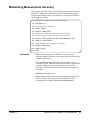
Measurement
Functions
The multimeter’s measurement functions are shown below. These functions
are typical of those required for many data acquisition and computer aided
test applications.
– DC Voltage
– RMS AC voltage
– 2-Wire Resistance (scanning multimeter only)
– 4-Wire Resistance
– Temperature (thermistors, RTDs, thermocouples)
Configuring the
Multimeter
Triggering the
Multimeter
The multimeter’s trigger system allows it to be internally or externally
triggered. The system enables you to scan a multiplexer channel list
multiple times, or in the stand-alone configuration, take multiple readings
per trigger. An on-board timer allows you to pace measurements.
Reading Storage
Readings are returned directly to the multimeter’s output buffer or are
stored in mainframe memory. The total number of readings which can be
stored (all multimeters combined) depends on the amount of memory
available. Each reading stored will consume four bytes of memory.
Saving Configurations
Electrical
Description
14
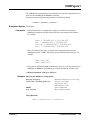
With MEASure or CONFigure, the multimeter is configured for
measurements using a single command. When necessary, low-level
commands are available to set configurations for unique applications. Such
commands, for example, allow you to enable autozero or offset
compensation, or change various analog-to-digital (A/D) converter
parameters.
To minimize repeated programming, up to 10 stand-alone multimeter
configurations can be saved and recalled. The configurations remain in
memory until a new configuration is saved or until power is cycled.
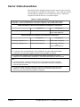
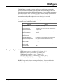
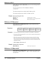
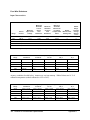
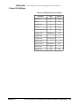
The electrical performance of the multimeter is summarized in Table 1-1.
Refer to Appendix A for a complete table of specifications.
Getting Started with the HP E1326B/E1411B Multimeter
Chapter 1
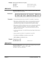
Table 1-1. HP E1326B/E1411B Operating Characteristics
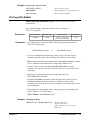
DC Voltage
Ranges
Resolution
Accuracy (90 days)
Max Rdgs/sec
0.125V, 1.0V, 8.0V, 64.0V, 300V full scale.
120nV on 0.125V range with 20/16.7 msec aperture time.
0.01%
13,150
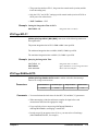
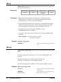
AC RMS Voltage
Ranges
Resolution
Accuracy (90 days)
Frequency Range
0.0875V, 0.7V, 5.6V, 44.8V, 300V full scale.
29.8nV on 0.0875V range with 320/267 msec aperture time.
0.625%
20 Hz to 10 kHz
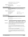
2-Wire and 4-Wire Resistance
Ranges
Resolution
Accuracy (90 days)
256Ω, 2048Ω, 16384Ω, 131072Ω, 1048576Ω full scale.
250mΩ on 256Ω range with 20/16.7 msec aperture time.
0.025%
Physical
Description
The 51⁄2 - digit multimeter occupies one B-Size or one C-Size mainframe
slot. However, the faceplate of the B-size multimeter covers up an
additional slot in the B-Size mainframe. This prevents another B-size card
from being installed in the slot directly above the multimeter. An internal
installation kit, discussed in Chapter 2, enables you to install the multimeter
internal to the HP 75000 Series B mainframe. This saves two externally
accessed slots.
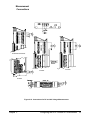
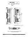
Input Terminals
There are four input terminals on the faceplate of the multimeter
(see Figure 2-7 on page 29). The terminals, which are isolated from chassis
ground, are used to connect input signals when the multimeter is used
stand-alone.
A high-to-low TTL pulse applied to the External Trigger port externally
triggers the multimeter. The Analog Bus and Digital Bus ports allow relay
and FET multiplexers to be connected to the multimeter.
Chapter 1
Getting Started with the HP E1326B/E1411B Multimeter
15
Introduction to Operation
This section contains information on checking communication between the
multimeter, mainframe, and computer. It includes information on returning
the multimeter to a known operating state should programming errors occur
or if you simply want to start over. It also shows how to send a command to
configure the multimeter and make a measurement.
Note
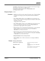
Multimeter Self-Test
The HP E1411B has a "Failed" annunciator and an "Access" annunciator on
the faceplate. The "Failed" annunciator turns on if the multimeter does not
properly respond during the mainframe’s power-on sequence. If this
occurs, return the multimeter to Hewlett-Packard for service. The "Access"
annunciator turns on each time the multimeter receives a command.
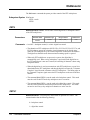
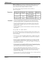
Once the mainframe completes its power-on sequence, the multimeter is
ready for use. Sending the self-test command is an easy way to verify that
you are properly addressing the multimeter. Also, the self-test is useful in
locating intermittent problems that might occur during operation. The
command used to execute the self-test is:
*TST?
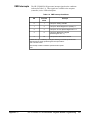
You can also run the self-test by selecting “TEST” from the multimeter’s
front panel menu on the HP E1301A mainframe. Upon execution, the
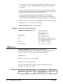
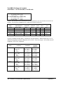
self-test resets the multimeter, performs the test, and returns one of the
codes listed in Table 1-2.
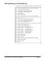
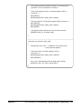
The following program executes the self-test. The program assumes the
mainframe (command module for C-size systems) is at primary HP-IB
address of 09 and the multimeter is at secondary address 03. The program
also assumes an HP 9000 Series 200/300 computer is used.
10
!Send the self-test command to the multimeter.
20
OUTPUT 70903;"*TST?"
30
!Enter and display the self-test code.
40
ENTER 70903;A
50
PRINT A
60
!Reset the multimeter.
70
OUTPUT 70903;"*RST"
80
END
After the test passes, always reset the multimeter to return it to a known state.
16
Getting Started with the HP E1326B/E1411B Multimeter
Chapter 1
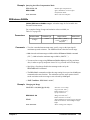
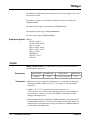
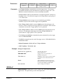
Table 1-2. HP E1326/E1411 Self-Test Codes
Self-Test
Code
Description
0
Test passed.
1
Multimeter does not respond to the self-test.
2
Invalid communication between the multimeter’s two on-board processors.
3
Data line test between the multimeter and the mainframe command module failed.
4
Invalid communication between the multimeter and mainframe command module.
If self-test code 1, 2, 3, or 4 occurs, return the multimeter to Hewlett-Packard for repair.
Note
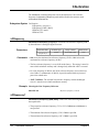
Resetting the
Multimeter
If the multimeter did not respond to the self-test, the address you specified
may be incorrect. Refer to Chapter 2 in this manual and the HP VXIbus
Systems Installation and Getting Started Guide.
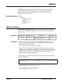
During operation, programming errors and other conditions may occur
making it necessary to reset the multimeter. This section shows you how to
reset and clear the multimeter, and read its error queue.
The multimeter is reset with the command:
*RST
which can be sent from an HP 9000 Series 200/300 computer as:
OUTPUT 70903;"*RST"
The multimeter can also be reset by pressing the green “Reset Instr” key on
the HP E1301A mainframe front panel. Note that the multimeter must first
be selected from the mainframe menu.
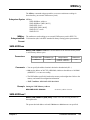
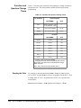
When resetting the multimeter:
• A front panel reset (“Reset Instr” key on the HP E1301A mainframe)
returns the multimeter to the idle state from the busy state and sets the
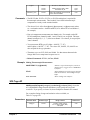
multimeter’s power-on configuration (Table 1-3). A front panel reset is
equivalent to clearing the multimeter followed by a reset.
• A reset from the computer (*RST) returns the multimeter to the idle
state from the busy state if the multimeter is busy due to a command
entered from the front panel. If the multimeter is busy due to a
command sent from the computer, you must clear the multimeter
before sending the reset. The reset sets the multimeter’s power-on
configuration.
Chapter 1
Getting Started with the HP E1326B/E1411B Multimeter
17
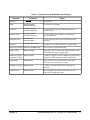
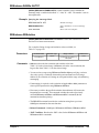
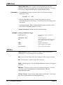
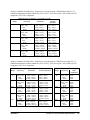
Table 1-3. HP E1326/E1411 Power-on Settings
Parameter
Setting
FUNCtion
VOLT:DC
VOLTage:RANGe
8V
RESistance:RANGe
16384Ω
VOLTage:RANGe:AUTO
ON
RESistance:RANGe:AUTO
ON
VOLTage:RESolution
7.629 µV
RESistance:RESolution
15.6 mΩ
VOLTage:APERture
16.7 ms or 20 ms (based on line frequency)
RESistance:APERture
16.7 ms or 20 ms (based on line frequency)
CALibration:LFRequency
Unchanged (factory setting = 60 Hz)
VOLTage:NPLC
1
RESistance:NPLC
1
RESistance:OCOMpensated OFF
18
CALibration:ZERO:AUTO
ON
TRIGger:COUNt
1
TRIGger:DELay:AUTO
ON
TRIGger:SOURce
IMM
SAMPle:COUNt
1
SAMPle:SOURce
IMM
Getting Started with the HP E1326B/E1411B Multimeter
Chapter 1
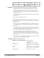
Clearing the Multimeter
When the multimeter is selected from the HP E1301A mainframe menu, the
multimeter is cleared by pressing the “Clear Instr” key on the front panel.
The multimeter is also cleared by sending the following command from an
HP 9000 Series 200 or Series 300 controller:
CLEAR 70903
Clearing the multimeter:
– allows you to regain control without cycling power and without
setting the power-on configuration.
– with the HP E1301A “Clear Instr” key terminates any
command entered from the front panel. A command sent from
the computer will still continue to execute.
– from the computer (CLEAR 70903) terminates any command
sent from the computer. A command entered from the
HP E1301A front panel will still continue to execute.
– erases any pending commands. For example, if commands are
sent from the computer to the multimeter while the multimeter is
waiting for an external trigger, the commands are buffered until
they can execute after the trigger is received. Clearing the
multimeter (from the computer) erases those commands.
Similarly, clearing the multimeter from the HP E1301A front
panel erases any pending front panel commands.
– if cleared from the HP E1301A front panel, the display buffer is
cleared. If cleared over HP-IB, the data in the output buffer is
erased.
The Error Queue
When an error occurs during operation, an error code and corresponding
message are stored in the multimeter’s error queue. If the Series B
mainframe has a display (HP E1301A) and the multimeter is being
monitored, the "err" annunciator will turn on.
Since many mainframes may not have a front panel display, the other way
to determine if an error has occurred is to read the error queue. This is done
with the command:
SYSTem:ERR?
The following program shows how the command is used to read and clear
the error queue.
10
!Declare a string variable in the computer to store the error message.
20
DIM Message$[256]
30
40
!Read the error queue until no errors remain.
!Print the error codes and messages.
50
60
70
80
90
100
Chapter 1
REPEAT
OUTPUT 70903;"SYST:ERR?"
ENTER 70903;Code,Message$
PRINT Code,Message$
UNTIL Code=0
END
Getting Started with the HP E1326B/E1411B Multimeter
19
The error queue can store up to 30 error messages which are retrieved in a
first in, first out (FIFO) manner. When there are no error messages in the
queue, a code of 0 and the message "No Error" are returned. Errors
generated during front panel operation are displayed but are not stored in
the error queue.
Note
Making a
Measurement
The HP E1326B/E1411B multimeter can be configured and make
measurements using the MEASure command. The following examples
show how it is used with the stand-alone and scanning multimeters.
Example: Making a
Measurement
(Stand-Alone
Multimeter)
This example uses the MEASure command to make a DC voltage
measurement on the terminals connected to the multimeter’s faceplate.
The reading is then entered into the computer and displayed.
Example: Making a
Measurement
(Scanning Multimeter)
20
Appendix B contains a list of error messages associated with the multimeter
and their causes.
10
OUTPUT 70903;"MEAS:VOLT:DC?"
20
ENTER 70903;Rdg
30
PRINT Rdg
40
END
This example uses the MEASure command to scan a list of multiplexer
channels and make a DC voltage measurement on each channel. The
readings are then entered into the computer and displayed.
10
DIM Rdgs(1:5)
20
OUTPUT 70903;"MEAS:VOLT:DC? (@100:104)"
30
ENTER 70903;Rdgs(*)
40
PRINT Rdgs(*)
50
END
Getting Started with the HP E1326B/E1411B Multimeter
Chapter 1
Chapter 2
Configuring the HP E1326B/E1411B
Multimeter
About This Chapter
This chapter contains information on connecting input signals to the
multimeter using multiplexers and using the terminals on the multimeter’s
faceplate. The main sections of the chapter are:
•
•
•
•
•
WARNING
Installation Overview. . . . . . . . . . . . . . . . . . . . . . . . . . . . . . .
Input Characteristics . . . . . . . . . . . . . . . . . . . . . . . . . . . . . . .
Connecting Input Signals. . . . . . . . . . . . . . . . . . . . . . . . . . . .
Carrier Cable Assemblies . . . . . . . . . . . . . . . . . . . . . . . . . . .
Additional Configurations . . . . . . . . . . . . . . . . . . . . . . . . . . .
Page 21
Page 28
Page 32
Page 37
Page 39
SHOCK HAZARD. Only service-trained personnel who are
aware of the hazards involved should install or configure the
multimeter. Remove all sources of power to the multimeter and
mainframe before removing the multimeter.
The maximum allowable input on the multimeter terminals is
300 V dc (450 V ac peak). Since the terminals are isolated from
the multimeter chassis, the potential between the terminals and
the chassis is equal to the value of the input signal.
Installation Overview
As mentioned in the HP VXIbus Systems Installation and Getting Started
Guide, each plug-in module has a row of switches which set the module’s
logical address. Based on this address, the system instrument within the
HP 75000 Series B mainframe and HP E1406A command module combines
the modules into virtual instruments. The instruments are programmed by a
computer using SCPI language or from a computer by writing commands
directly to the multimeter registers (see Appendix C).
This section shows the location of the multimeter’s logical address switch
and shows how it is set. It also mentions considerations when installing the
multimeter in the mainframe.
Chapter 2
Configuring the HP E1326B/E1411B Multimeter
21
Setting the Logical
Address Switch
Figure 2-1 shows the location and settings of the multimeter’s logical
address switch.
The switch has a factory setting of 24 which is equivalent to a secondary
HP-IB address of 03. If you have more than one multimeter, you must change
the logical address to some other multiple of 8 (for example, 32, 40, 48...), as
there can only be one instrument per secondary address.
Figure 2-1. HP E1326/1411 Logical Address Switch Settings
22
Configuring the HP E1326B/E1411B Multimeter
Chapter 2
Forming a Scanning
Multimeter
If multiplexers are used to form a scanning multimeter, they must be
assigned successive logical addresses beginning with the address
immediately following that of the multimeter. An example is shown in
Figure 2-2.
The scanning multimeter can consist of relay multiplexers, FET
multiplexers, or a combination of both. See “Connecting Multiplexers” on
page 30 for information on physically connecting the multiplexers to the
multimeter.
Figure 2-2. Setting Successive Logical Addresses to Form
an Instrument
Chapter 2
Configuring the HP E1326B/E1411B Multimeter
23
VXIbus Interrupt
Lines
The multimeter sends interrupts to, and receives acknowledgements from
the slot 0 module via the VXIbus backplane interrupt lines. Since the
multimeter is a nonprogrammable interrupter, the interrupt line is selected
with the multimeter’s IRQ jumper.
There are seven backplane interrupt lines. At the factory, the IRQ jumper is
set to line 1. The system instrument in the Series B mainframe is assigned
to each line, and the system instrument in the HP E1406A command module
is assigned to line 1 by default. Therefore, in Series B systems it is not
necessary to change the IRQ jumper setting. If the command module in
Series C systems is assigned another line and the multimeter is to use that
line, the IRQ jumper must be set accordingly. Figure 2-3 shows the location
of the jumpers used to select an interrupt line. For most applications where
the multimeter is installed in an HP 75000 Series B or Series C mainframe,
the jumpers do not have to be moved.
Note
Interrupt Priority
IRQ OFF is set when the multimeter is installed in systems without a Series B
mainframe or HP E1406A command module.
In the HP 75000 Series B and Series C mainframes, the VXIbus interrupt
lines have the same priority; therefore, interrupt priority is established by
installing modules in slots numerically closest to the slot 0 module. Thus,
slot 1 (internal on the Series B mainframe) has a higher priority than slot 2
(also internal), slot 2 has a higher priority than slot 3, and so on.
HP E1326B
HP E1411B
Interrupt
Jumper
Location
Interrupt
Jumper
Location
Figure 2-3. Interrupt Jumper Locations
24
Configuring the HP E1326B/E1411B Multimeter
Chapter 2
HP E1326B Internal
Installation
When the HP E1326B is installed in an HP E1300A/E1301A/E1302A
mainframe, it occupies one slot. However, the faceplate to which the input
terminals are connected covers up an additional slot. This prevents another
module from being installed in the slot directly above the multimeter.
To make the two slots available to other modules, the HP E1326B can be
installed internal to the mainframe (in slot 2) using an internal installation
kit (HP P/N E1326-80004).
Multimeter installation into the external slots is covered in the Installation
and Getting Started Guide. Instructions for installing the multimeter
internally are included in the installation kit.
Connecting the
HP E1326B Adapter
If the HP E1326B multimeter is installed internal to the HP E1300A/E1301A
mainframe, the HP E1326-80005 adapter can be used to provide HI, LO,
COM, and HI banana plug terminals for the multimeter. When the adapter
is connected as shown in Figure 2-4, the terminals, rather than the
multiplexer, are the input to the multimeter.
Figure 2-4. Connecting the HP E1326B Adapter
Chapter 2
Configuring the HP E1326B/E1411B Multimeter
25
Installing the
HP E1411B in a
Mainframe
The HP E1411B multimeter can be installed in any slot (except slot 0) in a
C-size VXIbus mainframe. Refer to Figure 2-5 to install the E1411B in a
mainframe.
Set the extraction levers out.
Slide the multimeter into any slot
(except slot 0) until the backplane
connectors touch.
Seat the multimeter into
the mainframe by pushing
in the extraction levers.
Tighten the top and bottom screws
to secure the multimeter to the
mainframe.
To remove the multimeter from the mainframe,
reverse the procedure.
Figure 2-5. Installing the HP E1411B Multimeter in a VXIbus Mainframe
26
Configuring the HP E1326B/E1411B Multimeter
Chapter 2
The Reference
Frequency
Setting the Reference
Frequency
In many data acquisition applications, DC voltage and resistance
measurements are often made in the presence of normal mode noise. This
type of noise emanates from the surrounding environment, primarily from
50 Hz and 60 Hz power lines. The HP E1326B/E1411B multimeter is able
to reject normal mode noise by using an integrating analog-to-digital (A/D)
converter. The integration process averages out the power line related noise
over an integer number of power line cycles (PLCs) during the A/D
conversion. The multimeter’s ability to reject noise at the power line
frequency is expressed in terms of normal mode rejection (NMR).
In certain applications, the multimeter’s power line frequency may be
different from the line frequency of the device being measured. Assume,
for example, the multimeter has a power line frequency of 60 Hz and the
device being measured has a line frequency of 400 Hz. Normal mode
rejection can be achieved by setting the reference frequency to 50 Hz.
This is done with the command:
CALibration:LFRequency frequency | MIN | MAX
frequency is power line frequency. Settings are 50 or 60.
MIN sets the minimum power line frequency (50 Hz).
MAX sets the maximum power line frequency (60 Hz).
The reference frequency is set to 60 Hz at the factory. The setting is stored
in non-volatile memory and is changed only when CALibration:LFRequency
is executed.
Querying the
Reference Frequency
The reference frequency is queried with the following commands.
See Chapter 5 for additional information about these commands.
CALibration:LFRequency?
CALibration:LFrequency? MIN | MAX
Chapter 2
Configuring the HP E1326B/E1411B Multimeter
27
Input Characteristics
The multimeter is a floating, balanced differential multimeter. Floating means
the multimeter’s input terminals are isolated from its chassis. A balanced
differential multimeter is one where the input impedance between HI and COM
is the same as the impedance between LO and COM (see Figure 2-6). The
only difference between the HI and LO terminals is the polarity.
Figure 2-6. A Floating, Balanced Differential Multimeter
28
Configuring the HP E1326B/E1411B Multimeter
Chapter 2
Input Terminals
CAUTION
The multimeter input terminals are shown in Figure 2-7. The maximum
input on the HI and LO terminals is 300 V dc (450 V ac peak). The
maximum amount of common mode voltage developed between LO and
COM and HI (current) and COM cannot exceed 15 V peak.
A maximum voltage of 300 V dc (450 V ac peak) is allowed on
the multimeter’s rear terminals. Multiplexers connected to the
multimeter reduce the voltage that can be applied between the
multiplexer’s High (H), Low (L), and Guard terminals, to the
level specified for the multiplexer. For example,
HP E1343A/44A 250 V dc or 354 V ac peak
HP E1345A/47A 120 V dc or 170 V ac peak
HP E1351A
14 V dc or ac peak
Mixing of multiplexer types reduces all voltage ratings to that of
the lowest rated multiplexer. For example, if an HP E1343A and
E1351A are connected to the same multimeter, then the system
rating is that of the E1351A, which is 14 V.
Figure 2-7. HP E1326B/E1411B Input Terminals
Chapter 2
Configuring the HP E1326B/E1411B Multimeter
29
Connecting
Multiplexers
In a scanning multimeter configuration, the multimeter is connected to the
multiplexers with an analog bus cable, or with the analog bus cable and a
digital bus cable. The cable(s) used is determined as follows:
1. If the scanning multimeter uses relay multiplexers only, the analog
bus cable is used.
2. If the scanning multimeter uses FET multiplexers only, the analog
bus cable and the digital bus cable are used.
3. If the scanning multimeter uses a combination of relay and FET
multiplexers, only the analog bus cable is used.
Figure 2-8 shows how the analog and digital bus cables are connected.
Figure 2-8. Connecting the Analog and Digital Bus Cables
30
Configuring the HP E1326B/E1411B Multimeter
Chapter 2
Analog Bus
Connections at the
Multimeter
The analog bus coming from the multiplexer consists of six lines. On the
multiplexer terminal block these lines are labeled:
H L G I+ I- IG
Where the ribbon cable connects the multiplexer to the multimeter the lines
are labeled:
H L G H L G
The lines are then connected to the multimeter’s HI LO COM HI lines as
shown in Figure 2-9.
Figure 2-9. Analog Bus Connections
Digital Bus Overview
The digital bus cable coordinates the operation (handshaking) between the
multimeter and FET multiplexers without involvement from the system
instrument. This enables the multimeter to scan the FET channels at a rate
of approximately 13,150 channels/sec.
The digital bus consists of a Voltmeter Complete line, an (external) Trigger
line, and ground. The handshake sequence is described in the following
steps and in Figure 2-10.
1. When a FET channel is closed, a "channel closed" signal is sent over
the Trigger line. This triggers the multimeter which, in turn, makes a
measurement.
2. When the measurement is finished, a "voltmeter complete" signal is
sent from the multimeter to the multiplexer on the Voltmeter
Complete line. This signal advances the scan to the next channel in
the list. When the channel is closed, the channel closed signal
triggers the multimeter and the process repeats.
Figure 2-10. Digital Bus Overview
Chapter 2
Configuring the HP E1326B/E1411B Multimeter
31
Connecting Input Signals
This section contains guidelines on connecting input signals to the
multimeter and shows the connections required to make the following
measurements:
•
•
•
•
Note
DC and AC RMS Voltage
2-Wire Resistance (including thermistors and RTDs)
4-Wire Resistance (including thermistors and RTDs)
Thermocouples
Refer to the HP E1355A - E1358A Strain Gage Multiplexers User’s Manual
for information on connecting strain gages.
Wiring
Considerations
To ensure accurate measurements, input signals should be connected to the
multimeter (via its rear terminals or a multiplexer) using a shielded
twisted-pair cable. Twisted-pair cables reduce magnetic (inductive) noise in
the measurement circuit. The shield reduces electrical (capacitive) noise.
Connecting the
COM Lead
To prevent the HI and LO terminals from floating from the COM terminal
and causing erratic overload readings, the COM terminal must be connected
to the signal source. If a shielded cable is used, connect one end of the
cable shield to the LO lead at the signal source, and connect the other end of
the cable shield to the COM (or guard) terminal. If a shielded cable is not
used, connect a COM (guard) lead with the LO lead AT THE SIGNAL
SOURCE. These connections (Figure 2-11), apply to measurement using
the rear terminals or multiplexers.
WARNING
The HI, LO, COM, HI terminals on the multimeter faceplate are
internally connected to the analog bus port. Thus, signals on
the analog bus (from a multiplexer) appear on the faceplate
terminals and vice versa.
Figure 2-11. Connecting the COM Lead
32
Configuring the HP E1326B/E1411B Multimeter
Chapter 2
Measurement
Connections
E1345A/47A/51A/53A
E1346A
E1352A
E1460A
Figure 2-12. Connections for DC and AC Voltage Measurements
Chapter 2
Configuring the HP E1326B/E1411B Multimeter
33
E1345A/47A/51A/53A
E1460A
E1346A
E1352A
Figure 2-13. Connections for 2-Wire Resistance Measurements
(Including Thermistors and RTDs)
Note
34
2-wire resistance measurements require the multiplexer modules shown
above. Resistance measurements using the multimeter terminals or directly
through the analog bus must be configured as 4-wire measurements.
Configuring the HP E1326B/E1411B Multimeter
Chapter 2
E1460A
E1345A/47A/51A/53A
NOTE: Channel Pairs are banks 0/4, 1/5, 2/6, and 3/7.
See Chapter 2 of the HP E1460A User’s Manual.
Figure 2-14. Connections for 4-Wire Resistance Measurements
(Including Thermistors and RTDs)
Chapter 2
Configuring the HP E1326B/E1411B Multimeter
35
E1476A
E1344A/47A/53A
Figure 2-15. Connections for Thermocouples
36
Configuring the HP E1326B/E1411B Multimeter
Chapter 2
Carrier Cable Assemblies
The following table and figures show the cables used to connect relay and
FET multiplexers to the HP E1411B multimeter. These cables are required
when the (B-Size) multiplexers are installed in the Series C mainframe
using the HP E1403B A/B-to-C-size module adapter.
Table 2-1. Cable Assemblies
Configuration 1: HP E1345A/46A/47A/55A or 56A (relay multiplexer) in HP E1403B module adapter.
Configuration 2: HP E1351A/52A/53A/57A or 58A (FET multiplexer) in HP E1403B module adapter.
Cable assemblies for HP E1411B multimeter-to-multiplexer connections
Configuration 1
Connecting the HP E1411B to:
E1326-61611 (analog bus)
Configuration 2
E1326-61611 (analog bus)
E1411-61601 (digital bus)
Cable assemblies for multiplexer-to-multiplexer connections
Configuration 1
Configuration 2
Connecting Configuration 1 to:
E1400-61605 (analog bus)
E1400-61605 (analog bus)
Connecting Configuration 2 to:
E1400-61605 (analog bus)
E1400-61605 (analog bus)
and
E1400-61601 (digital bus)
Examples:
1. To connect the HP E1411B multimeter to a FET multiplexer in the HP E1403B module adapter
(configuration 2), the analog and digital bus cables in kit E1400-80001 are required.
2. To connect a FET multiplexer in the HP E1403B module adapter (configuration 2) to a relay
multiplexer in the E1403B adapter (configuration 1), the E1400-61605 analog bus cable is required.
Notes:
1. The HP E1326-61611 analog bus cable and HP E1411-61601 digital bus cable are available
under kit part number E1411-80001. This kit is not included with the multimeter or multiplexers.
It must be ordered separately.
2. The HP E1400-61605 analog bus cable ships with the HP E1345A/46A/47A/55A and 56A relay
multiplexers. The HP E1400-61605 analog bus cable and HP E1400-61601 digital bus cable
ship with the HP E1351A/52A/53A/57A/58A FET multiplexers.
Chapter 2
Configuring the HP E1326B/E1411B Multimeter
37
Figure 2-16. Cables for B-Size Multiplexers in HP E1403B Adapter
38
Configuring the HP E1326B/E1411B Multimeter
Chapter 2
Additional Configurations
This section contains information on two additional configurations for the
multimeter:
• selecting VME RAM, and
• disabling front-panel for stand-alone applications.
Selecting VME RAM
Up to 12 Mbytes of VME RAM can be added to the B-size mainframe to
be used for multimeter reading storage. The following lists guidelines for
using VME RAM with the multimeter:
• Dynamic RAM must handle its own refresh, and not require any
command module activity.
• VME cards can never be a bus master.
– B-size mainframe does not have bus arbitration.
• VME cards must exclude the first and last 2 Mbytes of A24 space.
– B-size mainframe’s system ROM is located in the lower
2 Mbytes.
– B-size mainframe’s system RAM is located in the upper
2 Mbytes.
• VME RAM may not be used for IBASIC program memory.
The following lists guidelines in selecting a VME card:
Disabling
Front-panel for
Stand-alone
Applications
A24
A24 address space
D16
16 bits of data at a time
3U
A size slot
6U
B size slot
When using the HP E1326B Multimeter as a stand-alone instrument, the
HP E1301A front-panel keyboard can be disabled without disabling the
display. To disable the front-panel keyboard, use the following guidelines:
– send a "REMOTE" command to each instrument, and
– send a "LOCAL LOCKOUT" to the HP-IB interface.
This should allow the display to still work, but disable the keyboard and the
softkeys.
Chapter 2
Configuring the HP E1326B/E1411B Multimeter
39
Notes
40
Configuring the HP E1326B/E1411B Multimeter
Chapter 2
Chapter 3
Using the HP E1326B/E1411B Multimeter
About This Chapter
This chapter is a collection of example programs which show you how to
make measurements with various multimeter configurations. The examples
in this chapter include:
• Making a Single Measurement . . . . . . . . . . . . . . . . . . . . . . . Page 42
• Making a Burst of Measurements . . . . . . . . . . . . . . . . . . . . . Page 43
• Making an Externally Triggered Burst of
•
•
•
•
•
•
•
•
•
•
•
•
•
•
•
•
Using the Programs
Programming
Language
Measurements . . . . . . . . . . . . . . . . . . . . . . . . . . . . . . . . .
Making Multiple Burst Measurements . . . . . . . . . . . . . . . . .
Scanning a Channel List . . . . . . . . . . . . . . . . . . . . . . . . . . . .
Making Multiple Scans . . . . . . . . . . . . . . . . . . . . . . . . . . . . .
Making Multiple Paced Scans . . . . . . . . . . . . . . . . . . . . . . . .
Making an Externally Triggered Scan. . . . . . . . . . . . . . . . . .
Scanning Switchbox Channels (E1326B/1351A) . . . . . . . . .
Scanning Switchbox Channels (E1411B/1460A. . . . . . . . . .
Multiple High-Speed Scans . . . . . . . . . . . . . . . . . . . . . . . . . .
Maximizing Measurement Speed . . . . . . . . . . . . . . . . . . . . .
Changing the Data Format . . . . . . . . . . . . . . . . . . . . . . . . . . .
Using a PC, C Language, and the HP 82335 HP-IB
Interface Card . . . . . . . . . . . . . . . . . . . . . . . . . . . . . . . . .
Maximizing Measurement Accuracy. . . . . . . . . . . . . . . . . . .
Storing Readings in Shared Memory. . . . . . . . . . . . . . . . . . .
Checking for Errors . . . . . . . . . . . . . . . . . . . . . . . . . . . . . . . .
Synchronizing the Multimeter with a Computer . . . . . . . . . .
Additional Measurement Functions. . . . . . . . . . . . . . . . . . . .
Page 44
Page 45
Page 46
Page 47
Page 48
Page 49
Page 50
Page 52
Page 54
Page 56
Page 58
Page 60
Page 63
Page 64
Page 66
Page 68
Page 69
The purpose of the chapter is to provide example programs that show you
how to operate the multimeter. With minor modifications, these programs
can also be used for many of your applications.
The example programs are shown in the Hewlett-Packard BASIC language
and assume the multimeter is controlled from an HP 9000 Series 200/300
computer over the HP-IB. When using HP BASIC, a command is sent to
the multimeter with the OUTPUT statement:
OUTPUT 70903;"MEAS:VOLT:DC? (@100)"
The destination specified (70903) is the interface select code of the
computer (7), plus the HP-IB addresses of the HP 75000 Series B
mainframe or Series C command module (09), and the multimeter (03).
The multimeter command is enclosed between quotation marks. Use
ENTER to enter data from the multimeter is entered into the computer:
ENTER 70903;variable
Chapter 3
Using the HP E1326B/E1411B Multimeter
41
Multimeter Connections
The MEASure and
CONFigure Commands
Chapter 2 contains information on connecting input signals for the
measurements described in this chapter.
All of the example programs use the MEASure or CONFigure commands.
These commands configure the multimeter, and are equivalent to executing
several other multimeter commands. The CONFigure command is used in
place of MEASure when changes to the configuration set by either
command are required.
Recall from Chapter 1 that the HP E1326B/E1411B can function
stand-alone, or with multiplexers as a scanning multimeter instrument.
When programming, the stand-alone multimeter and scanning multimeter
are distinguished by the absence or presence of the (@channel_list)
parameter in the MEASure or CONFigure command. Chapter 4 provides
details on these commands and the multimeter configurations they set.
Measurement
Functions other than
DC Voltage
In each of the programs, the measurement function specified is DC voltage.
The function can be changed by changing the MEASure or CONFigure
command. The different functions available are shown following the last
example program.
Making a Single Measurement
This program makes a single DC voltage measurement on the terminals
connected to the multimeter’s faceplate using the configuration set by the
MEASure command.
Comments
10
!Clear and reset the multimeter.
20
CLEAR 70903
30
OUTPUT 70903;"*RST"
40
!Configure the multimeter and make a DC voltage measurement.
50
OUTPUT 70903;"MEAS:VOLT:DC?"
60
!Enter and display the reading on the computer.
70
ENTER 70903;A
80
PRINT A
90
END
• The scanning multimeter (multimeter plus multiplexers) is required
to make 2-wire measurements (resistance, thermistors, RTDs) or
thermocouple measurements.
42
Using the HP E1326B/E1411B Multimeter
Chapter 3
Making a Burst of Measurements
This program makes 100 DC voltage measurements on the terminals
connected to the multimeter’s faceplate.
Comments
10
!Dimension a computer array to store the readings.
20
DIM Rdgs(1:100)
30
!Clear and reset the multimeter.
40
CLEAR 70903
50
OUTPUT 70903;"*RST"
60
70
80
!Configure the multimeter for DC voltage measurements. Take a burst of 100
!readings, store the readings in mainframe memory until all readings are
!taken. Fetch the readings from memory and place them in the output buffer.
90
OUTPUT 70903;"CONF:VOLT:DC"
100
OUTPUT 70903;"
SAMP:COUN 100"
110
OUTPUT 70903;"INIT"
120
OUTPUT 70903;"FETCH?"
130
!Enter the readings into the computer. Display selected measurements.
140
ENTER 70903;Rdgs(*)
150
PRINT Rdgs(1),Rdgs(50),Rdgs(100)
160
END
• CONFigure sets a burst consisting of one measurement. The
SAMPle:COUNt command is used to set a burst of measurements
greater than one. Up to 16,777,215 measurements can be specified
with SAMPle:COUNt.
• When INIT follows CONFigure, the readings are stored in mainframe
memory. FETCH? retrieves the readings and places them in the
output buffer once all measurements are taken. Replacing INIT and
FETCH? with READ? returns the readings directly to the output
buffer. Readings should be stored in memory first, rather than
returned directly to the output buffer, when measurement speed is
critical.
• Readings are returned directly to the multimeter’s output buffer, or
are stored in mainframe memory on in memory shared by the
VXIbus system. The total number of readings which can be stored
depends on the amount of memory available. Each reading stored
will consume four bytes of memory.
• A burst of measurements (set by SAMPle:COUNt) can also be made
when scanning a single channel.
Chapter 3
Using the HP E1326B/E1411B Multimeter
43
Making an Externally Triggered Burst of Measurements
This program makes a burst of 10 measurements on the faceplate terminals
when the multimeter receives an external trigger.
10
!Dimension a computer array to store the readings.
20
DIM Rdgs(1:10)
30
!Clear and reset the multimeter.
40
CLEAR 70903
50
OUTPUT 70903;"*RST"
60
70
80
!Configure the multimeter for DC voltage measurements. Set the trigger
!source to an external trigger. Take a burst of 10 readings when the trigger
!occurs. Wait for the trigger then return the readings to the output buffer.
90
OUTPUT 70903;"CONF:VOLT:DC"
100
OUTPUT 70903;"
TRIG:SOUR EXT"
110
OUTPUT 70903;"
SAMP:COUN 10"
120
OUTPUT 70903;"READ?"
130
!Enter and display the readings on the computer.
140
ENTER 70903;Rdgs(*)
150
FOR I=1 TO 10
160
Comments
PRINT Rdgs(I)
170
NEXT I
180
END
• The multimeter is triggered when a high-to-low TTL signal is
applied to the "External Trigger" port.
• CONFigure sets the trigger source to the multimeter’s internal
trigger. The trigger source is changed with the TRIGger:SOURce
command. The sources available are:
IMM - immediate (internal) trigger
EXT - external trigger
BUS - triggered by *TRG or HP-IB group execute trigger
HOLD - suspend trigger
• CONFigure sets a burst consisting of one measurement. The
SAMPle:COUNt command is used to set a burst of measurements
greater than one. Up to 16,777,215 measurements can be specified
with SAMPle:COUNt.
• The multimeter output buffer can hold eight readings. When the
buffer fills, measurements are suspended until readings are read from
the buffer (by the computer) to make space available.
44
Using the HP E1326B/E1411B Multimeter
Chapter 3
Making Multiple Burst Measurements
This program makes multiple burst measurements with a 5 second delay
between bursts. There are three bursts, each consisting of 100 readings,
occurring 1 ms apart.
Comments
10
!Dimension a computer array to store the readings.
20
DIM Rdgs(1:300)
30
!Clear and reset the multimeter.
40
CLEAR 70903
50
OUTPUT 70903;"*RST"
60
70
80
90
100
!Configure the multimeter for DC voltage measurements (7.27V range). Set
!the aperture time for 100 ms and turn autozero off. Make a total of 3 bursts,
!with a 5 second delay between them. Set each burst to 100 readings, with
!each reading 1 ms apart. Store the readings in mainframe memory until all
!bursts have occurred.
110
OUTPUT 70903;"CONF:VOLT:DC 7.27"
120
OUTPUT 70903;"
VOLT:APER 100E-6"
130
OUTPUT 70903;"
CAL:ZERO:AUTO OFF"
140
OUTPUT 70903;"
TRIG:COUN 3"
150
OUTPUT 70903;"
TRIG:DEL 5"
160
OUTPUT 70903;"
SAMP:SOUR TIM"
170
OUTPUT 70903;"
SAMP:TIM 0.001"
180
OUTPUT 70903;"
SAMP:COUN 100"
190
OUTPUT 70903;"INIT"
200
OUTPUT 70903;"FETCH?"
210
!Enter the readings and display selected measurements.
220
ENTER 70903;Rdgs(*)
230
PRINT Rdgs(100),Rdgs(200),Rdgs(300)
240
END
• CONFigure sets an aperture time of 16.7 ms or 20 ms depending on
the line frequency. The VOLTage:APERture command is used to set
aperture times of 10 µs, 100 µs, 2.5 ms, 16.7 ms, 20 ms, 267 ms, and
320 ms. For this program, the 100 µs aperture time is the maximum
that allows the multimeter to sample the readings every 1 ms (see
Chapter 4).
• CONFigure turns autozero on. The command CALibration:ZERO:AUTO
is used to turn it off. Turning autozero off allows the readings in the
burst to occur at more precise, and smaller intervals.
• The trigger count is the number of triggers the multimeter is to
respond to before it returns to an idle state. In this program, the
multimeter responds to three internal triggers. CONFigure sets the
trigger count to 1. The command TRIGger:COUNt is used to set up
to 16,777,215 counts.
Chapter 3
Using the HP E1326B/E1411B Multimeter
45
• The trigger delay is the period between the trigger signal and the
start of the measurement (burst). The trigger delay set by
CONFigure is 0 seconds for the DC voltage function. The
TRIGger:DELay command is used to set delays up to 16.7 seconds.
• CONFigure sets the sample source such that there is a minimum
delay (sample rate) between measurements in a burst, and a burst
size of 1. The sample rate and burst size are changed with the
SAMPle:SOURce, SAMPle:TIMer, and SAMPle:COUNt commands.
SAMPle:SOURce selects the source which sets the sample rate.
SAMPle:TIMer sets the rate, and SAMPle:COUNt sets the number of
readings in the burst.
Scanning a Channel List
This program scans a channel list one time using the multimeter
configuration set by the MEASure command.
10
!Dimension a computer array to store the readings.
20
DIM Rdgs(1:16)
30
!Clear and reset the multimeter.
40
CLEAR 70903
50
OUTPUT 70903;"*RST"
60
70
!Configure the multimeter and make DC voltage measurements on
!channels 100 through 115.
80
OUTPUT 70903;"MEAS:VOLT:DC? (@100:115)"
90
!Enter and display the readings on the computer.
100
ENTER 70903;Rdgs(*)
110
FOR I=1 TO 16
120
Comments
PRINT Rdgs(I)
130
NEXT I
140
END
• The multimeter output buffer can hold eight readings. When the
buffer fills, measurements are suspended until readings are read from
the buffer (by the computer) to make space available.
46
Using the HP E1326B/E1411B Multimeter
Chapter 3
Making Multiple Scans
This program scans a channel list multiple times.
10
!Dimension a computer array to store the readings.
20
DIM Rdgs(1:20)
30
!Clear and reset the multimeter.
40
CLEAR 70903
50
OUTPUT 70903;"*RST"
60
70
!Configure the multimeter for DC voltage measurements. Scan the
!channel list five times.
80
OUTPUT 70903;"CONF:VOLT:DC (@100:103)"
90
OUTPUT 70903;"
100
OUTPUT 70903;"READ?"
110
!Enter and display the readings on the computer.
120
ENTER 70903;Rdgs(*)
130
FOR I=1 TO 20 STEP 4
140
Comments
TRIG:COUN 5"
PRINT Rdgs(I),Rdgs(I+1),Rdgs(I+2),Rdgs(I+3)
150
NEXT I
160
END
• For the scanning multimeter, CONFigure sets one scan (pass)
through the channel list. The TRIGger:COUNt command can specify
up to 16,777,215 scans.
• The multimeter makes one measurement per channel per scan.
However, multiple measurements per channel (per scan) can be
made when scanning a single channel. The number of measurements
taken during a single channel scan is set with the SAMPle:COUNt
command.
• The multimeter output buffer can hold eight readings. When the
buffer fills, measurements are suspended until readings are read from
the buffer (by the computer) to make space available.
Chapter 3
Using the HP E1326B/E1411B Multimeter
47
Making Multiple Paced Scans
This program makes multiple scans through a channel list with the scans
occurring at specified intervals.
10
!Dimension a computer array to store the readings.
20
DIM Rdgs(1:20)
30
!Clear and reset the multimeter.
40
CLEAR 70903
50
OUTPUT 70903;"*RST"
60
70
80
!Configure the multimeter for DC voltage measurements. Scan the
!channel list five times, with a two second delay between scans.
!Store the readings in mainframe memory.
90
OUTPUT 70903;"CONF:VOLT:DC (@100:103)"
100
OUTPUT 70903;"
TRIG:COUN 5"
110
OUTPUT 70903;"
TRIG:DEL 2"
120
OUTPUT 70903;"INIT"
130
OUTPUT 70903;"FETCH?"
140
!Enter and display the readings on the computer.
150
ENTER 70903;Rdgs(*)
160
FOR I=1 TO 20 STEP 4
170
Comments
PRINT Rdgs(I),Rdgs(I+1),Rdgs(I+2),Rdgs(I+3)
180
NEXT I
190
END
• For the scanning multimeter, CONFigure sets one scan (pass)
through the channel list. The TRIGger:COUNt command can specify
up to 16,777,215 scans.
• The delay between scans is the delay between the trigger signal and
the first channel in the list. There is no programmable delay between
subsequent channels in the list. The trigger delay set by CONFigure
is 0 seconds for the DC voltage function. The TRIGger:DELay
command is used to set delays up to 16.7 seconds.
• When scanning with the FET multiplexers, the sample period for
each channel can be specified with the SAMPle:TIMer command.
This feature is available with the FET multiplexers only.
• When INIT follows CONFigure, the readings are stored in mainframe
memory. FETCH? retrieves the readings and places them in the
output buffer once all measurements are taken. Replacing INIT and
FETCH? with READ? returns the readings directly to the output
buffer.
48
Using the HP E1326B/E1411B Multimeter
Chapter 3
Making an Externally Triggered Scan
This example makes one scan through a channel list when the multimeter
receives an external trigger.
10
!Dimension a computer array to store the readings.
20
DIM Rdgs(1:16)
30
!Clear and reset the multimeter.
40
CLEAR 70903
50
OUTPUT 70903;"*RST"
60
70
80
!Configure the multimeter for DC voltage measurements. Set the
!trigger source to an external trigger. Scan the channel list one time
!when the trigger is received.
90
OUTPUT 70903;"CONF:VOLT:DC (@100:115)"
100
OUTPUT 70903;"
110
OUTPUT 70903;"READ?"
120
!Enter and display the readings on the computer.
130
ENTER 70903;Rdgs(*)
140
FOR I=1 TO 16
150
Comments
TRIG:SOUR EXT"
PRINT Rdgs(I)
160
NEXT I
170
END
• The multimeter is triggered when a high-to-low TTL signal is
applied to the "External Trigger" port.
• CONFigure sets the trigger source to the multimeter’s internal
trigger. The trigger source is changed with the TRIGger:SOURce
command. The sources available are:
IMM - immediate (internal) trigger
EXT - external trigger
BUS - triggered by *TRG or HP-IB group execute trigger
HOLD - suspend trigger
• If programmed for multiple scans, multiple external triggers must
occur since each scan requires a trigger.
Chapter 3
Using the HP E1326B/E1411B Multimeter
49
Scanning Switchbox Channels (E1326B/E1351A)
In this example, the stand-alone multimeter (HP E1326B) scans 5 channels
of an HP E1351A FET multiplexer switchbox 100 times. The scanning
sequence is controlled with the digital bus.
10
!Dimension a controller array to store the readings.
20
DIM Rdgs(1:500)
30
40
!Reset the E1326B multimeter and the E1351A FET switchbox. Turn the
!multimeter monitor mode off to increase throughput.
50
OUTPUT 70903;"*RST"
60
OUTPUT 70903;"*OPC?"
70
ENTER 70903;Rst_done
80
OUTPUT 70914;"*RST"
90
OUTPUT 70914;"*OPC?"
100
ENTER 70914;Rst_done
110
OUTPUT 70903;"DISP:MON OFF"
120
130
140
150
160
!Configure the multimeter for measurements at its fastest rate. This
!includes a fixed range (7.27), a 10 µs aperture time (MAX), autozero
!off, and a sample period of 76 µs (SAMP:TIM MIN). Set the multimeter
!to make 500 measurements (5 channels/100 scans). Wait for the
!configuration to complete.
170
OUTPUT 70903;"CONF:VOLT:DC 7.27,MAX"
180
OUTPUT 70903;"
CAL:ZERO:AUTO OFF"
190
OUTPUT 70903;"
SAMP:COUN 500"
200
OUTPUT 70903;"
SAMP:SOUR TIM"
210
OUTPUT 70903;"
SAMP:TIM MIN"
220
OUTPUT 70903;"*OPC?"
230
ENTER 70903;Complete
240
250
260
!Configure the switchbox so that it receives its triggers over the digital bus.
!Route the signals on the multiplexer channels to the multimeter via the
!analog bus. Specify the scan list. Wait for the configuration to complete.
270
OUTPUT 70914;"TRIG:SOUR DBUS"
280
OUTPUT 70914;"SCAN:PORT ABUS"
290
OUTPUT 70914;"SCAN (@100:104)"
300
OUTPUT 70914;"*OPC?"
310
ENTER 70914;Complete
320
330
340
!Place the switchbox in the continuous scanning mode. Start the scan by
!closing the first multiplexer channel in the channel list. Wait for the
!command to complete and then trigger the multimeter.
350
OUTPUT 70914;"INIT:CONT ON"
360
OUTPUT 70914;"INIT"
370
WAIT .1
Continued on Next Page
50
Using the HP E1326B/E1411B Multimeter
Chapter 3
Comments
380
OUTPUT 70903;"INIT"
390
400
!Retrieve the readings from multimeter memory and enter them into the
!controller. Clear the switchbox to exit the continuous scanning mode.
410
OUTPUT 70903;"FETC?"
420
ENTER 70903;Rdgs(*)
430
CLEAR 70914
440
END
• The multimeter at secondary address 03 (logical address 24) is
connected to the switchbox at secondary address 14 (logical
address 112) with an analog bus cable and a digital bus cable.
• The analog bus carries the input signals to the multimeter. The
digital bus is used to carry a "multimeter complete" signal to the
switchbox to trigger the next channel closing.
• Because of the fast rate at which the FET channels close, the
multimeter is triggered once (INIT) and then samples continuously
(SAMP:COUN 500). Thus, the multimeter ignores the multiplexer
"channel closed" signal on the digital bus.
• Using this configuration, the multimeter is able to continuously scan the
switchbox and store readings in its memory at a 76 µs (13 kHz) rate.
Chapter 3
Using the HP E1326B/E1411B Multimeter
51
Scanning Switchbox Channels (E1411B/E1460A)
In this example, the stand-alone multimeter (HP E1411B) scans 64 channels
on an HP E1460A relay multiplexer switchbox. The scanning sequence is
controlled with the VXIbus TTLTrg trigger lines.
10
!Dimension a computer array to store the readings.
20
DIM Rdgs(1:64)
30
40
!Reset the E1411B multimeter and the E1460 switchbox. Wait for the
!resets to complete before continuing.
50
OUTPUT 70903;"*RST"
60
OUTPUT 70903;"*OPC?"
70
ENTER 70903;Rst_done
80
OUTPUT 70914;"*RST"
90
OUTPUT 70914;"*OPC?"
100
ENTER 70914;Rst_done
110
120
130
140
150
!Configure the multimeter for DC voltage measurements. Set its trigger
!source to TTL trigger line 0, set it to receive 64 triggers (one to measure
!each channel). Set the multimeter to output its channel closed pulse on
!TTL trigger line 1. Wait for the configuration to complete. Place the
!multimeter in the wait-for-trigger state.
160
OUTPUT 70903;"CONF:VOLT:DC"
170
OUTPUT 70903;"
TRIG:SOUR TTLT0"
180
OUTPUT 70903;"
TRIG:COUN 64"
190
OUTPUT 70903;"
OUTP:TTLT1:STAT ON"
200
OUTPUT 70903;"*OPC?"
210
ENTER 70903;Complete
220
OUTPUT 70903;"INIT"
230
240
250
260
270
!Configure the switchbox so that it receives its "channel advance" trigger
!on TTL trigger line 1, and that it outputs its "channel closed" pulse on
!TTL trigger line 0. Route the signals on the multiplexer channels to the
!multimeter via the analog bus. Specify the scan list. Wait for the
!configuration to complete before proceeding.
280
OUTPUT 70914;"TRIG:SOUR TTLT1"
290
OUTPUT 70914;"OUTP:TTLT0:STAT ON"
300
OUTPUT 70914;"SCAN:PORT ABUS"
310
OUTPUT 70914;"SCAN (@100:177)"
320
OUTPUT 70914;"*OPC?"
330
ENTER 70914;Complete
340
350
!Start the scan and the measurements by closing the first multiplexer
!channel in the channel list.
360
OUTPUT 70914;"INIT"
Continued on Next Page
52
Using the HP E1326B/E1411B Multimeter
Chapter 3
Comments
370
380
!Retrieve the readings from multimeter memory, enter and display them
!on the computer.
390
OUTPUT 70903;"FETC?"
400
ENTER 70903;Rdgs(*)
410
PRINT Rdgs(*)
420
END
• The multimeter and (multiplexer) switchbox have unique secondary
HP-IB addresses and as such, are two separate instruments. Input
signals from the switchbox are routed to the multimeter via the
analog bus. The scanning sequence is controlled with selected
TTLTrg trigger bus lines.
• The HP E1460A multiplexer has eight banks of channels with eight
channels in each bank. Channel numbers are 00 through 07 on
bank 0, up to 70 through 77 on bank 7. Since the switchbox consists
of only one multiplexer, the channel list for scanning 64 channels
is (@100:177).
• Additional information on triggering the multimeter is found in
Chapters 4 and 5. Information on the multimeter’s OUTPut
subsystem is contained in Chapter 5.
Chapter 3
Using the HP E1326B/E1411B Multimeter
53
Multiple High-Speed Scans
This example shows how a scanning multimeter consisting of the HP E1326B
multimeter and HP E1351A FET multiplexer is programmed for multiple scans
at a 13 kHz rate. The program scans 16 channels 100 times.
10
!Dimension a controller array to store the readings.
20
DIM Rdgs(1:1600)
30
40
!Reset the multimeter, turn monitor mode off, and then download the
!channel list to the FET multiplexer.
50
OUTPUT 70903;"*RST"
60
OUTPUT 70903;"*OPC?"
70
OUTPUT 70903;"DIAG:FETS 1"
80
ENTER 70903;Rst_done
90
OUTPUT 70903;"DISP:MON OFF"
100
OUTPUT 70903;"CONF:VOLT:DC 7.27,MAX,(@100:115)"
110
120
130
140
150
160
!Configure the multimeter for a burst of measurements. Specify a fixed
!range (7.27), a 10 µs aperture time (MAX), turn autozero off, and set a
!76 µs sample period (SAMP:TIM MIN). The number of measurements
!(sample count) is determined by multiplying the number of channels times
!the number of scans. In this example, 16 channels are scanned 100 times.
!Wait for the configuration to complete.
170
OUTPUT 70903;"CONF:VOLT:DC 7.27,MAX"
180
OUTPUT 70903;"
CAL:ZERO:AUTO OFF"
190
OUTPUT 70903;"
SAMP:COUN 1600"
200
OUTPUT 70903;"
SAMP:SOUR TIM"
210
OUTPUT 70903;"
SAMP:TIM MIN"
220
OUTPUT 70903;"*OPC?"
230
ENTER 70903;Complete
240
250
260
270
280
290
300
!The following commands set the FET multiplexer scanning configuration
!by writing directly to the multiplexer registers. Specifically, the first
!command transfers control of the scan from the multimeter to the user.
!The second command enables digital bus triggering, continuous scanning,
!and sets the pointer to the beginning of the scan list. The third command
!transfers control back to the multimeter. The fourth command closes the
!first channel in the list.
310
OUTPUT 70900;"VXI:WRITE 25,4,8"
320
OUTPUT 70900;"VXI:WRITE 25,6,26"
330
OUTPUT 70900;"VXI:WRITE 25,4,0"
340
OUTPUT 70900;"VXI:WRITE 25,4,16"
350
OUTPUT 70900;"*OPC?"
360
ENTER 70900;Complete
Continued on Next Page
54
Using the HP E1326B/E1411B Multimeter
Chapter 3
Comments
370
380
390
400
410
!Trigger the multimeter to start the measurements. Retrieve the readings
!from multimeter memory and enter them into the controller. Since the
!first channel in the scan list remains closed after the last multimeter
!complete signal is received, transfer control to the user, open the channel,
!and then transfer control to the multimeter.
420
OUTPUT 70903;"INIT"
430
OUTPUT 70903;"FETC?"
440
ENTER 70903;Rdgs(*)
450
OUTPUT 70900;"VXI:WRITE 25,4,8"
460
OUTPUT 70900;"VXI:WRITE 25,6,16"
470
OUTPUT 70900;"VXI:WRITE 25,4,0"
480
END
• The multimeter is connected to the multiplexer using the analog bus
cable and the digital bus cable.
• The analog bus carries the input signals to the multimeter. The
digital bus is used to carry a "multimeter complete" signal to the
multiplexer to trigger the next channel closing.
Because of the fast rate at which the FET channels close, the
multimeter is triggered once (INIT) and then samples continuously
(SAMP:COUN 1600). Thus, the multimeter ignores the multiplexer
"channel closed" signal on the digital bus.
Using this scanning multimeter configuration, the multimeter is able
to continuously scan the multiplexer channels and store readings in
its memory at a 76 µs (13 kHz) rate.
• The maximum number of continuous scans and measurements
depends on the amount of multimeter memory available.
• Detailed information on the FET multiplexer registers can be found
in the register-based programming section of the multiplexer user’s
manual.
Chapter 3
Using the HP E1326B/E1411B Multimeter
55
Maximizing Measurement Speed
This program shows the multimeter configuration required to make
measurements at the fastest possible rate (13150 readings/sec).
Comments
10
!Dimension a computer array to store the readings.
20
DIM Rdgs(1:500)
30
40
!Clear and reset the multimeter. For mainframes with a display and
!keyboard, turn off monitor mode so the measurements are not displayed.
50
CLEAR 70903
60
OUTPUT 70903;"*RST"
70
OUTPUT 70903;"DISP:MON OFF"
80
90
100
110
120
!Configure the multimeter for DC voltage measurements. Increase
!measurement speed by specifying a fixed range (7.27), the worst
!resolution (MAX), and turning autozero off. Specify the number of
!readings in the burst and set the fastest sample rate. Store the
!readings in mainframe memory.
130
OUTPUT 70903;"CONF:VOLT:DC 7.27,MAX"
140
OUTPUT 70903;"
CAL:ZERO:AUTO OFF"
150
OUTPUT 70903;"
SAMP:COUN 500"
160
OUTPUT 70903;"
SAMP:SOUR TIM"
170
OUTPUT 70903;"
SAMP:TIM MIN"
180
OUTPUT 70903;"INIT"
190
OUTPUT 70903;"FETC?"
200
!Enter the readings and display selected measurements.
210
ENTER 70903;Rdgs(*)
220
PRINT Rdgs(1),Rdgs(250),Rdgs(500)
230
END
• The 13 kHz reading rate is achieved under the following conditions:
function
= DC voltage
range
= fixed
resolution
= least
aperture time
= 10 µs
autozero
= off
sample rate
= 76 µs (MINimum)
reading storage
= mainframe (or shared) memory
In addition, there should be no activity by other instruments in the
mainframe.
56
Using the HP E1326B/E1411B Multimeter
Chapter 3
• The terms MIN and MAX often appear as parameter choices in a
command’s syntax. MIN selects the minimum numeric value for that
parameter. MAX selects the maximum numeric value. This
eliminates the need to look up specific numbers in the manual.
• In this program, note that MAX in the CONFigure command selects
the least resolution and sets the aperture time to 10 µs (see Table 4-5
on page 92). When measurement speed is critical, readings should
be stored in mainframe memory first, rather than returned directly to
the output buffer.
• The total number of readings which can be stored depends on the
amount of memory available. Each reading stored will consume four
bytes of memory.
• To increase the (throughput) speed at which measurement data is
transferred from the multimeter to the computer by the FETCh?
command, the multimeter’s output data format should be set to
REAL,64 or REAL,32 (see “Changing the Data Format” on page 58).
• The 13 kHz reading rate must be reduced to 12.82 kHz when the
sample count is greater than 32 k. Setting the SAMP:TIM to 78 µs
gives a reading rate of 12.82 kHz and allows the sample count to be
greater than 32 k.
CONF:VOLT:DC 7.27,MAX
CAL:ZERO:AUTO OFF
SAMP:SOUR TIM
SAMP:TIM 0.078
INIT
Chapter 3
Using the HP E1326B/E1411B Multimeter
57
Changing the Data Format
Throughput speed between the multimeter and computer is increased when
binary (rather than ASCII) data formats are used. The following program
changes the data format to REAL 64, and then makes a burst of 1,000
measurements on a single multiplexer channel.
Comments
10
20
30
40
!Dimension computer variables to store the data header and readings.
!Assign an input/output path between the multimeter and computer.
!This is a path for data in the REAL 64 format. Clear the path and
!reset the multimeter.
50
DIM Ndig$[1],Count$[9],Rdgs(1:1000)
60
ASSIGN @Dmm TO 70903;FORMAT OFF
70
CLEAR @Dmm
80
OUTPUT 70903;"*RST"
90
100
110
120
130
140
!Set the data format to REAL 64. Configure the multimeter for DC
!voltage measurements on multiplexer channel 0. Increase
!measurement speed by specifying a fixed range (58.1), turning
!autozero off, and setting the minimum aperture time. Specify the
!number of readings in the burst and set the fastest sample period.
!Store the readings in mainframe memory.
150
OUTPUT 70903;"FORM REAL,64"
160
OUTPUT 70903;"CONF:VOLT:DC 58.1,(@100)"
170
OUTPUT 70903;"
CAL:ZERO:AUTO OFF"
180
OUTPUT 70903;"
VOLT:APER MIN"
190
OUTPUT 70903;"
SAMP:COUN 1E3"
200
OUTPUT 70903;"
SAMP:SOUR TIM"
210
OUTPUT 70903;"
SAMP:TIM MIN"
220
OUTPUT 70903;"INIT"
230
OUTPUT 70903;"FETC?"
240
!Enter and display readings.
250
ENTER 70903 USING "#,X,K,K";Ndig$;Count$[1;VAL(Ndig$)]
260
ENTER @Dmm;Rdgs(*)
270
ENTER 70903;Lf$
280
PRINT Rdgs(*)
290
END
• The REAL,64 format is selected because the HP 9000 Series 200/300
computer stores readings in that format.
• REAL,64 data is transferred to the computer in the IEEE 488.2-1987
Definite Length Arbitrary Block format. Data in this format is
preceded by a header consisting of: # <non-zero digit>
<block length>. In this program, the header preceding the
measurement data is #48000. The 4 represents the number of digits
indicating the block length (8000), and 8000 is the block length
(1,000 readings * 8 bytes/reading).
58
Using the HP E1326B/E1411B Multimeter
Chapter 3
• When HP BASIC is used, the program’s ENTER @Dmm USING ...
statement is used to remove the Arbitrary Block header:
# - tells the computer to terminate the ENTER when all ENTER
statements have completed.
X - tells the computer to skip the first character of the Arbitrary
Block header (#).
K,K - stores the <non-zero digit> and <block length> portions of
the header in the Ndig$ and Count$ variables respectively.
More information on the Definite Length Arbitrary Block format is
located in Chapter 4.
• The ENTER @Dmm;Rdgs(*) statement enters the readings into
the computer. Since a Line Feed (LF) follows the last reading,
ENTER 70903;Lf$ removes the LF character from the multimeter
output buffer. If the LF character is not removed, Error -410 "Query
Interrupted" occurs the next time data is sent to the buffer. This
(third) ENTER statement is only required when using the REAL data
formats.
Chapter 3
Using the HP E1326B/E1411B Multimeter
59
Using a PC, C Language, and the
HP 82335 HP-IB Interface Card
The following benchmark program scans 50 channels, 40 times, and
compares each reading to upper and lower limits. The benchmarks varied
from 1.5 to 1.75 sec. The variation is caused by the time function in the
computer reporting back time with only 1 second increments.
The loop is repeated four times, thus: 6/4=1.5 and 7/4=1.75.
The line:
IOOUTPUTS(ADDR, "FORMAT REAL,32",14 );
programs the E1326B to output its data in a 32-bit real format.
The line:
IOENTERAB(ADDR, rdgs, &bytes, swap);
/* enter readings and remove block header */
enters the 32-bit numbers sent out by the DMM directly into a "float" type
C variable which is also 32-bits. Doing binary transfers this way is the
fastest method of moving data.
The program was Compiled in Borland TurboC, and was run on an
HP Vectra 25 MHz, 386 PC with an HP 82335 HP-IB card connected
to an HP E1301A mainframe with an HP E1326B multimeter and four
HP E1351A FET multiplexers.
/* BENCHMK.C - This is a benchmark program for the E1326B. The program */
/* scans 50 FET multiplexer channels 40 times, and repeats the sequence */
/* 4 times. The readings are compared to a set of limits after each scan. */
/* Results: 1.5000 to 1.75000 seconds for 40 scans of 50 channels */
/* Include the following header files */
#include <studio.h>
#include <stdlib.h>
#include <string.h>
#include <time.h>
#include <malloc.h>
#include <cfunc.h>
/* This file is from the HP-IB Command Library Disk */
#define ADDR 70903L
/* I/O path from PC to the E1326 scanning multimeter */
/* Function Prototypes */
void rst_clr(void);
void scan_mult(void);
void check_error(char *func_tion);
/******************************************************************/
Continued on Next Page
60
Using the HP E1326B/E1411B Multimeter
Chapter 3
void main(void)
/* run the program */
{
clrscr();
/* clears screen (turbo C only) */
rst_clr();
/* reset the scanning multimeter */
scan_mult(); /* function to configure multimeter and take readings */
}
/******************************************************************/
void scan_mult(void)
{
time_t T1, T2;
int c = 0, i = 0, j = 0, length = 0, swap = 0, bytes = 0;
float *rdgs, rdy;
char lf_remove[1];
/* dynamically allocate memory for readings */
rdgs = malloc(8000 * sizeof(float));
/* float = 32-bit real number */
/* set number of bytes placed in memory, and number of bytes read */
swap = size of (float);
bytes = 8000 * swap;
/* place 4 bytes/reading in memory */
/* read 32,000 bytes */
/* configure the scanning multimeter and wait for configuration to complete */
IOOUTPUTS(ADDR, "CONF:VOLT:DC
(@1(00:15),2(00:15),3(00:15),4(00:01))", 51);
IOOUTPUTS(ADDR, "VOLT:RANGE 10;:CAL:ZERO:AUTO
OFF;:VOLT:APERMIN",47 );
IOOUTPUTS(ADDR, "FORMAT REAL,32",14 );
IOOUTPUTS(ADDR, "*OPC?", 5); /* wait for configuration to complete */
IOENTER(ADDR, &rdy);
/* enter *OPC? response from multimeter */
/* function call to check for multimeter configuration errors */
check_error("scan_mult");
T1 = time(NULL);
/* get start time */
/* program loop which set 4, 40 scan measurements */
for (c = 0; c 4; c++)
{
/* program loop which scans the 50 multiplexer channels 40 times */
for (i = 0; i 40; i++)
{
IOOUTPUTS(ADDR, "INIT", 4);
/* trigger multimeter */
IOOUTPUTS(ADDR, "FETCH?", 6);
/* fetch the readings */
IOENTERAB(ADDR, rdgs, &bytes, swap);
/* enter readings and remove
block header*/
/* remove line feed which trails the last data byte */
length = 1;
IOENTERS(ADDR, lf_remove, &length);
/* compare each reading to a set of limits */
for (j = 0; j 50; j++)
{
Continued on Next Page
Chapter 3
Using the HP E1326B/E1411B Multimeter
61
if (rdgs[j] -.5 || rdgs[j] = .5)
printf("\n%f", rdgs[j]);
}
}
}
T2 = time(NULL);
/* get stop time */
/* calculate time for measurements */
printf("\nTime = %f seconds", (difftime(T2,T1)/4));
free(rdgs);
}
/******************************************************************/
void rst_clr(void)
{
/* Reset and clear the scanning multimeter */
IOOUTPUTS(ADDR, "*RST;*CLS", 9);
/* Send (9) characters */
}
/******************************************************************/
void check_error(char *func_tion)
{
char
into[161];
int length = 160;
IOOUTPUTS(ADDR, "SYST:ERR?", 9);
/* Query error register */
IOENTERS(ADDR, into, &length);
/* Enter error message */
if (atoi(into) != 0)
/* Determine if error is present
If errors present, print and exit */
{
while (atoi(into) != 0)
{
printf("Error %s in function %s\n\n", into, func_tion);
IOOUTPUTS(ADDR, "SYST:ERR?", 9);
IOENTERS(ADDR, into, &length);
}
exit(1);
}
}
62
Using the HP E1326B/E1411B Multimeter
Chapter 3
Maximizing Measurement Accuracy
This program makes DC voltage measurements on three channels using the
multimeter configuration which makes the most accurate measurements.
Note that measurement accuracy also depends on wiring practices and the
surrounding environment.
Comments
10
!Dimension a computer array to store the readings.
20
DIM Rdgs(1:3)
30
!Clear and reset the multimeter.
40
CLEAR 70903
50
OUTPUT 70903;"*RST"
60
70
!Configure the multimeter for DC voltage measurements.
!Set autorange and select the minimum (best) resolution.
80
OUTPUT 70903;"CONF:VOLT:DC AUTO,MIN,(@101:103)"
90
OUTPUT 70903;"READ?"
100
!Enter and display the readings on the computer.
110
ENTER 70903;Rdgs(*)
120
PRINT Rdgs(*)
130
END
• MIN sets the minimum (best) resolution for the range set by
autorange. MIN also indirectly selects the aperture time for the most
accurate measurements.
• The terms MIN and MAX often appear as parameter choices in a
command’s syntax. MIN selects the minimum numeric value for that
parameter. MAX selects the maximum numeric value for the
parameter. This eliminates the need to look up specific numbers in
the manual.
• CONFigure turns autozero on.
• When making resistance measurements (including thermistors and
RTDs), accuracy can often be increased by turning on offset
compensation (for example, RESistance:OCOMpensated).
Chapter 3
Using the HP E1326B/E1411B Multimeter
63
Storing Readings in Shared Memory
The following program stores the multimeter readings on a VME memory card.
64
10
20
30
!Dimension computer variables to store the data header and readings.
!Assign an input/output path between the multimeter and computer.
!Clear the path and reset the multimeter.
40
DIM Ndig$[1],Count$[9],Rdgs(1:200,1:1000)
50
ASSIGN @Dmm TO 70903;FORMAT OFF
60
CLEAR @Dmm
70
OUTPUT 70903;"*RST"
80
90
100
!Specify the starting memory location in shared memory (800000h),
!specify the amount of memory to use (1 MByte), direct the readings to the
!memory card.
110
OUTPUT 70903;"MEM:VME:ADDR #H800000"
120
OUTPUT 70903;"MEM:VME:SIZE #H100000"
130
OUTPUT 70903;"MEM:VME:STAT ON"
140
150
!Set the data format to REAL,64. Configure the multimeter to take 200,000
!readings at its fastest possible rate.
160
OUTPUT 70903;"FORMAT REAL,64"
170
OUTPUT 70903;"CONF:VOLT:DC 58.1"
180
OUTPUT 70903;"
CAL:ZERO:AUTO OFF"
190
OUTPUT 70903;"
VOLT:APER MIN"
200
OUTPUT 70903;"
SAMP:COUN 200000"
210
OUTPUT 70903;"
SAMP:SOUR TIM"
220
OUTPUT 70903;"
SAMP:TIM MIN"
230
OUTPUT 70903;"INIT"
240
OUTPUT 70903;"FETC?"
250
!Enter the readings.
260
ENTER 70903 USING "#,X,K,K";Ndig$;Count$[1;VAL(Ndig$)]
270
ENTER @Dmm;Rdgs(*)
280
ENTER 70903;Lf$
290
END
Using the HP E1326B/E1411B Multimeter
Chapter 3
Comments
• Once the INIT command completes, the readings in shared memory
are available to any device. The readings at this time are in 32-bit
REAL format.
• When the shared memory state is on (MEM:VME:STAT ON), all
readings are stored in VME memory regardless of the number of
readings taken.
• The VME memory location and memory size can be specified in
decimal or hexadecimal. Configuration of the VME memory card
should be covered in the manual which came with the card.
• In this program, the readings retrieved from shared memory are
64-bit REAL numbers in the IEEE 488.2-1987 Definite Length
Arbitrary Block format. Page 58 contains an example which
describes the Arbitrary Block format and additional format
information is located in Chapter 4.
• When running HP BASIC, an array dimension can have no more
than 32767 elements. Thus, to store 200,000 readings, a
two-dimensional array is declared.
Chapter 3
Using the HP E1326B/E1411B Multimeter
65
Checking for Errors
The following program is a method of checking for errors as you program the
multimeter. The program monitors the multimeter’s Standard Event Status
Register for an error condition. If no errors occur, the multimeter functions as
programmed. If errors do occur, the multimeter interrupts the computer and the
error codes and messages are read from the multimeter error queue.
The computer commands shown are for an HP 9000 Series 200/300
computer running HP BASIC and controlling the multimeter over HP-IB.
10
20
!Call computer subprogram "Errmsg" if a multimeter programming error
!occurs. Enable the computer to respond to an interrupt from the multimeter.
30
ON INTR 7 CALL Errmsg
40
ENABLE INTR 7;2
50
60
70
!Unmask the Event Status bit in the multimeter’s Status Byte register.
!Unmask the multimeter error conditions in its Standard Event Status
!register.
80
90
OUTPUT 70903;"*SRE 32"
OUTPUT 70903;"*ESE 60"
100
!At this point, the multimeter is programmed for the intended application.
110
OUTPUT 70903;"...
120
OUTPUT 70903;"...
130
140
150
!Allow the computer time to respond if an error occurs during the
!multimeter configuration or measurement. Process the measurement
!data if no error occurs.
160
WAIT 2
170
ENTER 70903;...
180
PRINT ...
190
END
200
210
220
230
!When an error occurs, clear the multimeter to regain control. Execute a
!Serial Poll to clear the service request bit in the Status Byte register.
!Read all error messages in the multimeter error queue. Clear all bits in
!the multimeter Standard Event Status Register.
240
SUB Errmsg
250
DIM Message$[256]
260
CLEAR 70903
270
B=SPOLL(70903)
280
REPEAT
290
300
310
66
OUTPUT 70903;"SYST:ERR?"
ENTER 70903;Code,Message$
PRINT Code,Message$
320
UNTIL Code=0
330
OUTPUT 70903;"*CLS"
340
STOP
350
SUBEND
Using the HP E1326B/E1411B Multimeter
Chapter 3
Comments
• If you have an HP 75000 Series B mainframe with a keyboard, errors
can be monitored by selecting "Monitor" from the multimeter menu.
If errors occur when the program executes, the "err" annunciator will
appear. Entering SYST:ERR? repeatedly from the keyboard reads
all of the messages in the error queue.
• An overload condition (for example, reading = +9.900000E+037)
sets the Device Dependent Error bit in the Standard Event Status
Register. In this program, this condition interrupts the computer
which then calls the subprogram. However, an overload does not
generate an error message so 0 "No Error" is displayed.
• The B-size VXIbus Mainframe User’s Manual contains detailed
information on the Status and Standard Event Status Registers.
Chapter 3
Using the HP E1326B/E1411B Multimeter
67
Synchronizing the Multimeter with a Computer
This is an example of how an HP 9000 Series 200/300 computer can
monitor the multimeter to determine when data is available. This allows the
computer to perform other functions while the multimeter is making
measurements. When the readings are available, the computer stops its
current function and enters the data.
10
!Dimension a computer array to store the readings.
20
DIM Rdgs(1:15)
30
40
!Clear and reset the multimeter. Unmask the Message Available (MAV)
!bit (4) in the Status Byte Register.
50
OUTPUT 70903;"*CLS"
60
OUTPUT 70903;"*RST"
70
OUTPUT 70903;"*SRE 16"
80
90
100
!Configure the multimeter for DC voltage measurements. Make 5 scans
!through the channel list with each scan 5 seconds apart. Store the
!readings in mainframe memory.
110
OUTPUT 70903;"CONF:VOLT:DC (@104:106)"
120
OUTPUT 70903;"
TRIG:COUN 5"
130
OUTPUT 70903;"
TRIG:DEL 5"
140
OUTPUT 70903;"INIT"
150
OUTPUT 70903;"FETC?"
160
170
180
!Monitor the message available bit. Have the computer perform another
!function (e.g. display a message) until the bit indicating a reading is
!available is set. Enter and display the readings.
190
WHILE NOT BIT (SPOLL(70903),4)
200
DISP "WAITING FOR DATA"
210
WAIT 1
220
DISP ""
230
WAIT 1
240
END WHILE
250
ENTER 70903;Rdgs(*)
260
FOR I=1 TO 15 STEP 3
270
Comments
PRINT Rdgs(I),Rdgs(I+1),Rdgs(I+2)
280
NEXT I
290
END
• Readings are not fetched from memory until all scans and all
measurements have completed.
• The message available bit (MAV) is set when the first reading
retrieved from memory enters the output buffer.
• Only the data from one command can be in the output buffer or in
mainframe memory. Synchronizing the computer with the
multimeter in this manner ensures the data is entered into the
computer before it is overwritten by data from another command.
68
Using the HP E1326B/E1411B Multimeter
Chapter 3
Additional Measurement Functions
The following MEASure and CONFigure statements can be substituted into
the example programs to make measurements other than DC voltage.
Additional Stand-Alone
Multimeter Functions
The following statements can be substituted into the program “Making a
Single Measurement” on page 42.
!AC voltage.
OUTPUT 70903;"MEAS:VOLT:AC?"
!4-wire resistance.
OUTPUT 70903;"MEAS:FRES?"
!4-wire thermistor (type = 2252, 5000, 10000).
OUTPUT 70903;"MEAS:TEMP? FTH,type"
!4-wire RTD (type = 85, 92).
OUTPUT 70903;"MEAS:TEMP? FRTD,type"
The following statements can be substituted into the programs where the
faceplate terminals are used to make multiple reading bursts or multiple
burst measurements.
!AC voltage.
OUTPUT 70903;"CONF:VOLT:AC"
!4-wire resistance.
OUTPUT 70903;"CONF:FRES"
!4-wire thermistor (type = 2252, 5000, 10000).
OUTPUT 70903;"CONF:TEMP FTH,type"
!4-wire RTD (type = 85, 92).
OUTPUT 70903;"CONF:TEMP FRTD,type"
Additional Scanning
Multimeter Functions
The following statements can be substituted into the program “Scanning a
Channel List” on page 46.
!AC voltage.
OUTPUT 70903;"MEAS:VOLT:AC? (@channel_list)"
!2-wire resistance.
OUTPUT 70903;"MEAS:RES? (@channel_list)"
!4-wire resistance (channels available are 00 through 07).
OUTPUT 70903;"MEAS:FRES? (@channel_list)"
!Thermocouple (type = B, E, J, K, N14, N28, R, S, T).
OUTPUT 70903;"MEAS:TEMP? TC,type,(@channel_list)"
Chapter 3
Using the HP E1326B/E1411B Multimeter
69
!2-wire thermistor (type = 2252, 5000, 10000).
OUTPUT 70903;"MEAS:TEMP? THER,type,(@channel_list)"
!4-wire thermistor (type = 2252, 5000, 10000)
!Channels available are 00 through 07.
OUTPUT 70903;"MEAS:TEMP? FTH,type,(@channel_list)"
!2-wire RTD (type = 85, 92).
OUTPUT 70903;"MEAS:TEMP? RTD,type,(@channel_list)"
!4-wire RTD (type = 85, 92)
!Channels available are 00 through 07.
OUTPUT 70903;"MEAS:TEMP? FRTD,type,(@channel_list)"
The following statements can be substituted into the programs where the
multimeter configuration is set by CONFigure (and low-level commands).
!AC voltage.
OUTPUT 70903;"CONF:VOLT:AC (@channel_list)"
!2-wire resistance.
OUTPUT 70903;"CONF:RES (@channel_list)"
!4-wire resistance (channels available are 00 through 07).
OUTPUT 70903;"CONF:FRES (@channel_list)"
!Thermocouple (type = B, E, J, K, N14, N28, R, S, T).
OUTPUT 70903;"CONF:TEMP TC,type,(@channel_list)"
!2-wire thermistor (type = 2252, 5000, 10000).
OUTPUT 70903;"CONF:TEMP THER,type,(@channel_list)"
!4-wire thermistor (type = 2252, 5000, 10000)
!Channels available are 00 through 07.
OUTPUT 70903;"CONF:TEMP FTH,type,(@channel_list)"
!2-wire RTD (type = 85, 92).
OUTPUT 70903;"CONF:TEMP RTD,type,(@channel_list)"
!4-wire RTD (type = 85, 92).
!Channels available are 00 through 07.
OUTPUT 70903;"CONF:TEMP FRTD,type,(@channel_list)"
Note
70
The HP E1326B/E1411B multimeter also makes strain gage measurements.
Refer to the HP E1355A - E1358A Strain Gage Multiplexers User’s Manual
for example programs.
Using the HP E1326B/E1411B Multimeter
Chapter 3
Additional Function
Using the HP E1345A
Multiplexer
This is an example of how to setup scanning when using an HP E1345A
multiplexer configured as a switchbox and the HP E1326B multimeter used
with no multiplexers assigned to it. The two subprograms used in this
example are Scan_100µsec and Scan_10µsec. Configuration for this
example is as follows:
Connect two cables as:
• Multimeter’s "Ext Trig" to "Trig Out" on the E1406 or E1300/E1301.
• Multimeter’s "VM Compl" to "Trig In" on the E1406 or E1300/E1301.
The two different subprograms are used to demonstrate a more effective
method of scanning (Scan_100µs) and a less effective method of scanning
(Scan_10µs). Comments follow the program and subprograms providing
information about the instruments execution.
Scan_100µs demonstrates the multimeter set for an aperture of 100µs and
achieves a scan rate of 123/sec in the E1300 B-size mainframe. Whereas,
Scan_10µs demonstrates the multimeter set for an aperture of 10 µs and
achieves a decrease in scanning speed.
10
20
30
40
50
60
70
80
90
100
105
110
120
130
140
150
160
170
180
190
200
210
220
230
240
250
260
270
280
300
!Define I/O paths.
!
ASSIGN @Sys TO 70900
ASSIGN @Dvm TO 70903
ASSIGN @Sw TO 70916
!
!Setup for timeouts and errors.
!
ON TIMEOUT 7,5 GOTO End
ON ERROR RECOVER Kaboom
!
!Supply your own application code for Main.
!
Main
PRINT "Checking for E13xx_errors at the end of the program"
E13xx_errors
!
!Subprogram Kaboom.
!
Kaboom:PRINT ""
PRINT ERRM$
PRINT "Checking for E13xx Errors as a BASIC Error has occurred"
E13xx_errors
End:END
!
!Subprogram to read all errors from E13xx instruments.
!
SUB E13xx_errors
.
.
.
SUBEND
Continued on Next Page
Chapter 3
Using the HP E1326B/E1411B Multimeter
71
310
320
330
340
350
360
370
380
390
400
410
420
430
440
450
460
470
480
490
500
510
520
530
540
550
560
570
580
590
600
610
620
630
640
650
660
670
680
690
700
710
720
730
740
750
760
765
770
780
790
800
810
820
830
840
!
!Subprogram Scan_100µs.
!
SUB Scan_100us
COM @Sys,@Dvm,@Sw
DIM Readings(0:15)
!
!Clear and reset multimeter.
!
CLEAR @Dvm
OUTPUT @Dvm"*RST;*CLS;*OPC?"
ENTER @Dvm;A
!
!Clear and reset switch.
!
CLEAR @Sw
OUTPUT @Sw;"*RST;*CLS;*OPC?"
ENTER @Sw;A
!
!Send commands to multimeter.
!
OUTPUT @Dvm;"CONF:VOLT:DC 11"
OUTPUT @Dvm;"VOLT:APER 100E-6"
OUTPUT @Dvm;"CAL:ZERO:AUTO ONCE"
OUTPUT @Dvm;"TRIG:SOUR EXT;COUNT 16"
OUTPUT @Dvm;"*OPC?"
ENTER @Dvm;A
OUTPUT @Dvm;"INIT"
!
!Send commands to switch.
!
OUTPUT @Sw;"OUTP ON"
OUTPUT @Sw;"TRIG:SOUR EXT"
OUTPUT @Sw;"SCAN:MODE VOLT"
OUTPUT @Sw;"SCAN:PORT ABUS"
OUTPUT @Sw;"SCAN (@100:115)"
OUTPUT @Sw;"*OPC?"
ENTER @Sw;A
!
!Get readings.
!
Start=TIMEDATE
OUTPUT @Sw;"INIT"
OUTPUT @Dvm;"FETCH?"
ENTER @Dvm;Readings(*)
Stop=TIMEDATE
PRINT "Scan Rate with Multimeter Aperture at 100us ";16/(Stop-Start)
SUBEND
!
!Subprogram Scan_10µs.
!
SUB Scan_10us
COM @Sys,@Dvm,@Sw
DIM Readings(0:15)
!
Continued on Next Page
72
Using the HP E1326B/E1411B Multimeter
Chapter 3
850
860
870
880
890
900
910
920
930
940
950
960
970
980
990
1000
1010
1020
1030
1040
1050
1060
1070
1080
1090
1100
1110
1120
1130
1140
1150
1160
1170
1180
1190
1200
1210
1220
1230
1240
1250
!Clear and reset multimeter.
!
CLEAR @Dvm
OUTPUT @Dvm;"*RST;*CLS;*OPC?"
ENTER @Dvm;A
!
!Clear and reset switch.
!
CLEAR @Sw
OUTPUT @Sw;"*RST;*CLS;*OPC?"
ENTER @Sw;A
!
!Send commands to multimeter.
!
OUTPUT @Dvm;"CONF:VOLT:DC 11"
OUTPUT @Dvm;"VOLT:APER 10E-6"
OUTPUT @Dvm;"CAL:ZERO:AUTO ONCE"
OUTPUT @Dvm;"TRIG:SOUR EXT;COUNT 16"
OUTPUT @Dvm;"*OPC?"
ENTER @Dvm;A
OUTPUT @Dvm;"INIT"
!
!Send commands to switch.
!
OUTPUT @Sw;"OUTP ON"
OUTPUT @Sw;"TRIG:SOUR EXT"
OUTPUT @Sw;"SCAN:MODE VOLT"
OUTPUT @Sw;"SCAN:PORT ABUS"
OUTPUT @Sw;"SCAN (@100:115)"
OUTPUT @Sw;"*OPC?"
ENTER @Sw;A
!
!Get readings.
!
Start=TIMEDATE
OUTPUT @Sw;"INIT"
OUTPUT @Dvm;"FETCH?"
ENTER @Dvm;Readings(*)
Stop=TIMEDATE
PRINT "Scan Rate with Multimeter Aperture at 10us ";16/(Stop-Start)
SUBEND
Results of this program are as follows:
Scan Rate with Multimeter Aperture at 100µs: 123.072300469
Scan Rate with Multimeter Aperture at 10µs: 4.48178352225
Checking for E13xx Errors at the end of the program:
DVM ERROR: "No error"
SYSTEM ERROR: "No error"
SWITCH ERROR: "No error"
Chapter 3
Using the HP E1326B/E1411B Multimeter
73
Notes
74
Using the HP E1326B/E1411B Multimeter
Chapter 3
Chapter 4
Understanding the HP E1326B/E1411B
Multimeter
About This Chapter
This chapter describes the parameters which configure the multimeter and
helps you determine settings to optimize performance. Information on
triggering the multimeter and on saving multimeter configurations in
memory is also included.
The chapter is divided into the following sections:
•
•
•
•
•
•
•
Note
Using MEASure and CONFigure Commands . . . . . . . . . . .
How to Make Measurements . . . . . . . . . . . . . . . . . . . . . . . . .
Data Formats and Destinations . . . . . . . . . . . . . . . . . . . . . . .
Measurement Functions . . . . . . . . . . . . . . . . . . . . . . . . . . . . .
Multimeter Parameters. . . . . . . . . . . . . . . . . . . . . . . . . . . . . .
Triggering the Multimeter . . . . . . . . . . . . . . . . . . . . . . . . . . .
Saving Multimeter Configurations . . . . . . . . . . . . . . . . . . . .
Page 76
Page 78
Page 80
Page 86
Page 91
Page 101
Page 114
Throughout this chapter, the HP E1326B/E1411B multimeter is referred to
as a "scanning multimeter" or a "stand-alone multimeter".
"Scanning" implies that one or more multiplexers are used with the
multimeter and are part of the same instrument (i.e. same HP-IB secondary
address).
"Stand-alone" means the multimeter is the only device at that secondary
address.
Chapter 4
Understanding the HP E1326B/E1411B Multimeter
75
Using MEASure and CONFigure Commands
Each time the multimeter makes a measurement, it does so from a
configuration based on several parameters. The easiest way to set these
parameters is with the MEASure and CONFigure commands:
MEASure:measurement?
[range|AUTO|DEF|MIN|MAX[,resolution|DEF|MIN|MAX]][,(@channel_list)]
CONFigure:measurement
[range|AUTO|DEF|MIN|MAX[,resolution|DEF|MIN|MAX]][,(@channel_list)]
MEASure:TEMPerature? transducer,type[,(@channel_list)]
CONFigure:TEMPerature transducer,type[,(@channel_list)]
Executing these high-level commands is equivalent to setting up the
multimeter with the commands shown in Table 4-1 on page 77. Note that
specifying a channel list identifies a scanning multimeter. No channel list
identifies a stand-alone multimeter.
Note
76
If a channel list is the only parameter specified in the MEASure or
CONFigure command, it must be separated from the command header by a
space, rather than a comma (e.g. MEAS:VOLT:DC? (@100)).
Understanding the HP E1326B/E1411B Multimeter
Chapter 4
Table 4-1. Configurations Using MEASure and CONFigure
Parameter
Command
Setting
Function
As specified.
Range
VOLTage:RANGe
RESistance:RANGe
As specified or autorange.
Resolution
VOLTage:RESolution
RESistance:RESolution
As specified or a function of range and aperture or
integration time.
Aperture Time
VOLTage:APERture
RESistance:APERture
16.7 ms (60 Hz), 20 ms (50 Hz), or based on the
specified resolution.
Integration Time
VOLTage:NPLC
RESistance:NPLC
1 power line cycle (PLC) or based on the specified
resolution.
Autozero
CALibration:ZERO:AUTO
ON; autozero is performed after every measurement.
Offset Compensation RESistance:OCOMpensated
Trigger Source
TRIGger:SOURce
OFF; resistance measurements only.
IMM; trigger signal is always true. Measurement is taken
when multimeter goes to Trigger State.
Number of Triggers TRIGger:COUNt
or Number of Scans
Trigger Delay
TRIGger:DELay
Readings per Trigger SAMPle:COUNt
Sample Period
SAMPle:SOURce
1; number of triggers issued or number of scans through
channel list before multimeter returns to Idle State.
- delays are 0 seconds for DC voltage and
resistance, 0.5 seconds for AC voltage.
AUTO
1; number of measurements taken when trigger is
received.
IMM; period between measurements or the period
between FET multiplexer scans.
Chapter 4
Understanding the HP E1326B/E1411B Multimeter
77
How to Make Measurements
This section explains when you should use MEASure or CONFigure to
configure the multimeter. It also shows you how to make measurements
once the configuration is set.
Using MEASure
When MEASure is used, the measurement is taken automatically after the
configuration is set. For example, executing MEASure as:
MEAS:VOLT:DC? 0.91,0.953E-6,(@100:104)
makes measurements on channels 100 through 104 after setting the function
to DC voltage, the range to 0.91 V, the resolution to 0.953 µV, and the
remainder of the parameters as shown in Table 4-1 on page 77.
Because the measurement is taken immediately, variations to the multimeter
configuration are limited to the parameters within the MEASure command
(range, resolution, channel list).
Using CONFigure
Use CONFigure for applications requiring a configuration different from
that available with MEASure. CONFigure does not make a measurement
after setting the configuration. Any of the low-level commands
(see Table 4-1 on page 77) can be used to change selected parameters
before a measurement is made.
Assume an application requires the following configuration:
•
•
•
•
•
•
4-wire resistance measurements
1861 ohm range
Maximum (best) resolution
Measure four multiplexer channels
Offset compensated measurements
Three scans (passes) through the channel list
MEASure cannot be used since it turns offset compensation off
(RES:OCOM OFF). MEASure also sets the multimeter to make one scan
(TRIGger:COUNt 1), while the application requires three scans.
By setting the configuration with CONFigure, the low-level commands
RESistance:OCOMpensated and TRIGger:COUNt can be used to turn offset
compensation ON and set the desired number of scans:
CONF:FRES 1861,MAX,(@100:103)
RES:OCOM ON
TRIG:COUN 3
78
Understanding the HP E1326B/E1411B Multimeter
Chapter 4
Making Measurements
When Using CONFigure
To make a measurement the multimeter must be in the wait-for-trigger state
when a trigger signal occurs. The MEASure command automatically places
the multimeter in the "wait state" after setting the configuration. When
CONFigure is used, the multimeter must be placed in the wait state with the
command:
READ? (readings are sent to the output buffer)
or
INIT[:IMMediate] (readings are stored in memory)
These commands follow CONFigure as shown below:
CONF:FRES 1861,MAX,(@100:103)
RES:OCOM ON
TRIG:COUN 3
READ?
CONF:FRES 1861,MAX,(@100:103)
RES:OCOM ON
TRIG:COUN 3
INIT
Note
READ? and INIT will make measurements upon execution if TRIG:SOUR IMM
(trigger signal always true) remains set. If the trigger source is changed
following the CONFigure command, execution of the READ? or INIT
commands will place the multimeter in the wait-for-trigger state; however, a
measurement will not be made until a trigger from the specified source occurs.
Chapter 4
Understanding the HP E1326B/E1411B Multimeter
79
Data Formats and Destinations
The HP E1326B/E1411B multimeter allows you to specify the
measurement (data) format and reading destination parameters which affect
throughput speed. This section identifies the formats available and shows
you how to display and store measurements.
Data Formats
The multimeter data formats are selected with the command:
FORMat[:DATA] <type> [,<length>]
The formats (and lengths) are shown in Table 4-2.
Table 4-2. Multimeter Data Formats
Type
ASCII
Representation
Bytes/Reading
+-1.234567E+-123
15
REAL 64
# <non-zero digit> <block length> <8-bit data bytes>
8
REAL 32
# <non-zero digit> <block length> <8-bit data bytes>
4
REAL 64 and REAL 32 numbers are transferred to the computer in the IEEE 488.2-1987
Definite Length Arbitrary Block format. Data in this format is preceded by a header
consisting of # <non-zero digit> <block length>. <non-zero digit> indicates the number of
digits representing <block length>. <block length> indicates the number of 8-bit data bytes
which follow. The following examples show how to interpret the Arbitrary block header.
REAL, 32
#14
#240
#44000
<4 bytes>
1 reading
<40 bytes>
10 readings
<4000 bytes> 1,000 readings
REAL, 64
#18
#280
#48000
<8 bytes>
1 reading
<80 bytes>
10 readings
<8000 bytes> 1,000 readings
The default format is ASCII. Readings in ASCII are followed by a comma (,).
A line feed (LF) and End-Or-Identify (EOI) follow the last reading in all
formats.
Specifying a Format
The following program segment shows you how to select a data format.
Chapter 3 contains an example on selecting a format and entering data with the
definite length arbitrary block header into an HP Series 200/300 computer.
FORM REAL,64
CONF:FRES 1861,MAX,(@100:103)
RES:OCOM ON
TRIG:COUN 3
READ?
80
Understanding the HP E1326B/E1411B Multimeter
Chapter 4
Overload Indications
The multimeter indicates an overload condition (input greater than the
selected range can measure) by displaying or storing:
±9.900000E+037
for the measurement. For temperature measurements:
9.910000E+037
indicates an overload condition.
An overload sets the Device Dependent Error bit in the Standard Event
Status Register. However, the overload does not generate an error message.
Reading
Destinations
Reading Destination
vs. Data Format
Measurements can be displayed on the HP E1301A mainframe, returned to
the output buffer and entered into a computer, or stored in memory. This
section explains how a reading destination is selected.
The data formats available depend on the reading destination. Table 4-3
shows the data formats available for each reading destination.
Table 4-3. Reading Destination vs. Data Format
Destination
Destination =
Mainframe Display
Formats
Display
ASCII / REAL 64-bit / REAL 32-bit
Output Buffer
ASCII / REAL 64-bit / REAL 32-bit
Mainframe Memory/
VME Memory Card
REAL 32-bit
When a measurement is made by entering commands from the HP E1301A
mainframe front panel, the reading is displayed on the front panel.
Readings are also displayed when commands are sent from a computer and
the multimeter’s monitor mode is on.
Although REAL,64 and REAL,32 are accepted formats, readings displayed
in those formats will not resemble the measured values.
Destination = Computer
When multimeter measurements are made using:
MEASure:measurement? ...
or
READ?
the readings are available to the computer via the output buffer. The
following examples show how data (ASCII format) is entered into an
HP 9000 Series 200/300 computer using HP BASIC.
Chapter 4
Understanding the HP E1326B/E1411B Multimeter
81
Example: Entering
Data into the Computer
(measurements using
MEASure)
Example: Entering
Data into the Computer
(measurements using
READ?)
10
!Declare computer array to store 5 readings.
20
REAL Dc_rdgs(1:5)
30
!Configure multimeter and take the measurements.
40
OUTPUT 70903;"MEAS:VOLT:DC? (@100:104)"
50
!Enter readings into the computer.
60
ENTER 70903;Dc_rdgs(*)
70
!Display readings on computer.
80
PRINT Dc_rdgs(*)
90
END
10
!Declare computer array to store 12 readings.
20
REAL Ohm_rdgs(1:12)
30
!Configure the multimeter.
40
OUTPUT 70903;"CONF:FRES 1861,MAX,(@100:103)"
50
OUTPUT 70903;"
RES:OCOM ON"
60
OUTPUT 70903;"
TRIG:COUN 3"
70
!Put multimeter in wait-for-trigger state; take readings.
80
OUTPUT 70903;"READ?"
90
!Enter readings into the computer.
100
ENTER 70903;Ohm_rdgs(*)
110
!Display readings on the computer.
120
PRINT Ohm_rdgs (*)
130
END
The data returned by commands such as MEASure or READ? must be
entered into the computer before another command is executed. Otherwise,
Error -410,“Query Interrupted” occurs and the data will be overwritten if
data is generated by the next command.
Destination =
Mainframe Memory
A few words about mainframe memory:
1. The E1301A memory is built into the mainframe whereas the
E1405A/E1406A memory is not built-in.
2. Data is stored in mainframe and shared memory by executing the
INIT command.
3. Reading rates are increased when the readings are stored in
mainframe memory. Storing readings in memory also ensures that
the sample rate is maintained at a constant value.
82
Understanding the HP E1326B/E1411B Multimeter
Chapter 4
4. Data stored in memory overwrites the data from a previous command.
5. Each reading stored in memory is four bytes (REAL 32-bit). This
format cannot be changed.
6. Each multimeter instrument within the HP 75000 Series B or Series C
mainframe is allocated enough memory to store a minimum of
100 readings.
If greater than 100 readings are requested, the mainframe multiplies
the TRIGger:COUNt setting by the SAMPle:COUNt setting to
determine the exact number. If enough memory is available, an
additional amount is allocated to the multimeter and the readings are
stored. If enough memory is not available, an error message occurs
and the command is aborted.
The number of additional readings which can be stored in memory
depends on the amount of memory in your system and on the number
of instruments which use the memory.
7. The memory allocated to the multimeter above the amount required
to store 100 readings remains dedicated to that multimeter until *RST
is executed or until power is cycled. Once de-allocated, the memory
is available to any instrument.
Example: Storing
Readings in Mainframe
Memory
To store measurements in mainframe memory, execute:
INIT[:IMMediate]
following the CONFigure command (or any applicable low-level commands).
Retrieving Data From
Mainframe Memory
10
!Configure the multimeter.
20
OUTPUT 70903;"CONF:FRES 1861,MAX,(@100:103)"
30
OUTPUT 70903;"
RES:OCOM ON"
40
OUTPUT 70903;"
TRIG:COUN 3"
50
60
!Place the multimeter in the wait-for-trigger state, store the readings
!in memory.
70
OUTPUT 70903;"INIT"
Data stored in mainframe memory is retrieved using:
FETCh?
Once the data is fetched, it is available to the computer via the output
buffer. Refer to the next example.
Chapter 4
Understanding the HP E1326B/E1411B Multimeter
83
Example: Retrieving
Data from Memory
Destination =
Shared Memory
10
!Declare computer array to store 12 readings.
20
REAL Ohm_rdgs(1:12)
30
!Configure the multimeter.
40
OUTPUT 70903;"CONF:FRES 1861,MAX,(@100:103)"
50
OUTPUT 70903;"
RES:OCOM ON"
60
OUTPUT 70903;"
TRIG:COUN 3"
70
80
!Place the multimeter in the trigger state, store the readings in
!mainframe memory.
90
OUTPUT 70903;"INIT"
100
!Retrieve readings from mainframe memory.
110
OUTPUT 70903;"FETCh?"
120
!Enter readings into computer.
130
ENTER 70903;Ohm_rdgs(*)
140
!Display readings on computer.
150
PRINT Ohm_rdgs (*)
160
END
Multimeter measurements can also be stored in memory shared by the
VXIbus system (VME Memory Card). The commands used to specify the
memory location and direct the readings to shared memory are:
MEMory:VME:ADDRess <address>
MEMory:VME:SIZE <bytes>
MEMory:VME:STATe <mode>
Chapter 3 contains an example on storing readings in shared memory.
The MEMory command is covered in Chapter 5.
84
Understanding the HP E1326B/E1411B Multimeter
Chapter 4
Reading
Destination
Summary
The reading destination you select will depend on your application.
However, consider the following when selecting a destination:
1. Use READ? or MEASure? to return readings to the output buffer
when throughput speed is not important or when the number of
measurements is too large to store in mainframe memory.
2. Use INIT to store readings in mainframe memory when speed is
important. Use FETCh? to retrieve the readings.
3. Use the MEMory commands and INIT to store readings in shared
memory (VME memory card) when speed is important and when the
readings will not fit in mainframe memory. Use FETCh? to retrieve
the readings.
In addition to selecting a destination, you may want to determine
beforehand the number of readings that can be saved in the B-size
mainframe RAM. Consider the following when determining the number of
readings that can be saved:
• Select your System Instrument.
• Send "DIAG:RDIS:CRE? MAX".
• Divide the number returned by four (4)
(this determines the approximate number of readings that can be saved).
You can also determine if a certain number of readings can be stored in the
B-size mainframe RAM by doing the following:
• Select the E1326B multimeter.
• Send "SAMP:COUNt nnn" command
(where nnn is the number of readings).
• Look for an "OUT OF MEMORY" error message
(if the message is NOT generated, then nnn readings can be stored).
Chapter 4
Understanding the HP E1326B/E1411B Multimeter
85
Measurement Functions
The HP E1326B/E1411B multimeter can make the following measurements:
– DC Voltage
– RMS AC Voltage
– 2-Wire Resistance
– 4-Wire Resistance
– Temperature
Note
DC Voltage
Measurements
The HP E1326B/E1411B multimeter also makes 1⁄4 bridge, 1⁄2 bridge, and
full bridge strain measurements. Refer to the HP E1355A - E1358A Strain
Gage Multiplexer User’s Manual for descriptions of these functions.
The multimeter can measure DC voltages up to 300 V (170 V with
multiplexers), with resolution down to approximately 30 nV depending on the
range and aperture or integration time. Selectable integration times of 1 or 16
power line cycles (PLC) provide normal mode rejection for measurements in
the presence of noise.
The DC voltage function is specified as:
VOLTage:DC
and generally appears in the MEASure and CONFigure commands as:
MEAS:VOLT:DC? ...
CONF:VOLT:DC ...
RMS AC Voltage
Measurements
The multimeter can measure RMS AC voltages up to 450 Vpeak
(170 Vpeak with multiplexers, 15 Vpeak with FET multiplexers), at
frequencies from 20 Hz to 10 kHz. Measurement resolution down to
approximately 30 nV is achieved with the appropriate range and aperture
or integration time settings. The AC measurements are AC-coupled. This
means that for an AC signal with a DC offset, only the AC amplitude is
measured. The DC offset is prevented (blocked) from reaching the
measurement circuitry of the multimeter.
The multimeter uses a true RMS converter for AC voltage measurements.
This allows accurate measurement of voltages that are noisy, distorted, or
non-sinusoidal such as square waves, triangle waves, sawtooths, and so on.
86
Understanding the HP E1326B/E1411B Multimeter
Chapter 4
The AC voltage function is specified as:
VOLTage:AC
and generally appears in the MEASure and CONFigure commands as:
MEAS:VOLT:AC? ... [(@channel_list)]
CONF:VOLT:AC ... [(@channel_list)]
Resistance
Measurements
How Resistance is
Measured
The multimeter can measure resistance up to 1.048 MΩ. Measurement
resolution down to 60 µΩ is achieved with the appropriate range and
aperture or integration time settings. Measurements can be made using a
2-wire or 4-wire configuration.
The multimeter measures resistance by turning on an internal current source
which induces a voltage across the unknown resistance. The induced
voltage is measured and is divided by the amount of current applied. The
result is the "measured" resistance (resistance = voltage/current).
Table 4-4 shows the amount of current applied to the unknown resistance
for a given range. Consider that the current flowing through the resistance
will cause a certain amount of self-heating, thus changing the resistance.
The effects of self-heating can be minimized by selecting a higher range
since less current is applied. However, measurement resolution is also
decreased.
Table 4-4. Current Source Values
Range
256 Ω
2048 Ω
16384 Ω
131072 Ω
1048576 Ω
Two-Wire vs. Four-Wire
Measurements
Chapter 4
Current
488 mA
488 µA
61 µA
61 µA
7.6 µA
The multimeter uses separate "sense" and "source" terminals when making
resistance measurements. The sense terminals measure (sense) the input
signal. The source terminals route current from the current source through
the unknown resistance. When the scanning multimeter makes a 2-wire
resistance measurement, the multiplexer connects these terminals together.
Thus, the input is sensed and the current is sourced through essentially the
same terminals. When the stand-alone multimeter is used, you must
connect the sense and source terminals to the resistance being measured.
This is a 4-wire configuration and the measurement must be specified
accordingly. Only 4-wire measurements can be made with the stand-alone
multimeter. Two-wire and 4-wire measurements can be made with the
scanning multimeter.
Understanding the HP E1326B/E1411B Multimeter
87
Two-Wire
Measurements
Two-wire measurements are useful in applications where test lead
resistance is not critical. Because the multimeter measures the total
resistance between its terminals, lead resistance that is large relative to the
unknown resistance will cause inaccurate measurements. Thus, for all
resistance measurements and especially those on the lower ranges, the leads
should be as short as possible.
Two-wire measurements are specified as:
RESistance
This function appears in the MEASure and CONFigure commands as:
MEAS:RES? ...(@channel_list)
CONF:RES ...(@channel_list)
Four-Wire
Measurements
For applications which require accurate resistance measurements or where
long test leads are used, the 4-wire configuration should be used. In the
4-wire configuration, errors due to test lead resistance are eliminated since
only the voltage induced across the unknown resistance is measured.
Four-wire measurements are specified as:
FRESistance
This function appears in the MEASure and CONFigure commands as:
MEAS:FRES?...[(@channel_list)]
CONF:FRES ...[(@channel_list)]
Channel Pairs
Temperature
Measurements
Thermistor
Measurements
Four-wire measurements with multiplexers use channel pairs. Channel pairs
on the HP E1345A 16-channel multiplexer, for example, are channels 00 and
08, 01 and 09, 02 and 10, ... 07 and 15. The lower channel in the channel pair
(00, 01, 02) is the sense channel. The higher channel (08, 09, 10) is the source
channel. When specifying a channel list, the lower "sense" channels are
specified.
The multimeter can make temperature measurements using specific
thermistors, thermocouples, and RTDs.
The thermistor types supported are 2252 Ω, 5000 Ω, and 10000 Ω. Use
thermistors that match the Omega 440xx series temperature response
curves. Thermistor measurements can be made in either a 2-wire or 4-wire
configuration. Two-wire measurements require the scanning multimeter.
Two-wire thermistor measurements are specified as:
TEMP THERmistor,type
88
Understanding the HP E1326B/E1411B Multimeter
Chapter 4
This function appears in the MEASure and CONFigure commands as:
MEAS:TEMP? THER,type,(@channel_list)
CONF:TEMP THER,type,(@channel_list)
Four-wire measurements are specified as:
TEMP FTHermistor,type
This function appears in the MEASure and CONFigure commands as:
MEAS:TEMP? FTH,type[,(@channel_list)]
CONF:TEMP FTH,type[,(@channel_list)]
Thermocouple
Measurements
Thermocouple measurements require the HP E1344A, E1347A, E1353A, or
HP E1476A multiplexers which are thermocouple compensated. The
thermocouple types supported are B, E, J, K, N14, N28, R, S, and T.
Thermocouple measurements are specified as:
TEMP TCouple,type
and appear in the MEASure and CONFigure commands as:
MEAS:TEMP? TC,type,(@channel_list)
CONF:TEMP TC,type,(@channel_list)
You can also measure the temperature of the reference thermistor on the
HP E1344A, E1347A, E1353A, or E1476A multiplexers as shown below:
MEAS:TEMP? THER,5000,(@nn93)
where nn is the multiplexer card number.
RTD Measurements
The RTD types supported are 85 (alpha = 0.00385) and 92 (alpha = 0.00392).
RTD measurements can be made in either a 2-wire or 4-wire configuration.
Two-wire measurements require the scanning multimeter.
Two-wire RTD measurements are specified as:
TEMP RTD,type
The function appears in the MEASure and CONFigure commands as:
MEAS:TEMP? RTD,type,(@channel_list)
CONF:TEMP RTD,type,(@channel_list)
Chapter 4
Understanding the HP E1326B/E1411B Multimeter
89
Four-wire measurements are specified as:
TEMP FRTD,type
The function appears in the MEASure and CONFigure commands as:
MEAS:TEMP? FRTD,type[,(@channel_list)]
CONF:TEMP FRTD,type[,(@channel_list)]
Note
Specifying a
Function
When making temperature measurements with the MEASure command, the
question mark (?) must be inserted between TEMP and the temperature
transducer used. Also, if a channel list immediately follows the transducer, it
must be separated by a comma (,) (e.g. MEAS:TEMP? THER,5000,(@100)).
The measurement functions described previously are represented by the
"measurement" parameter in the MEASure and CONFigure commands:
MEASure:measurement?
[range|AUTO|DEF|MIN|MAX[,resolution|DEF|MIN|MAX]][,(@channel_list)]
CONFigure:measurement
[range|AUTO|DEF|MIN|MAX[,resolution|DEF|MIN|MAX]][,(@channel_list)]
When using the stand-alone multimeter, the low-level command:
FUNCtion:function
can be used to change the measurement function without causing a complete
reconfiguration of the multimeter. The stand-alone multimeter functions
which can be changed are:
VOLT:DC
VOLT:AC
FRESistance
The next example shows you how to change from a DC voltage
measurement to a 4-wire resistance measurement.
90
Understanding the HP E1326B/E1411B Multimeter
Chapter 4
Example: Changing
Measurement
Functions with
FUNCtion
10
!Configure for DC voltage measurement.
20
CONF:VOLT:DC
30
!Put multimeter in wait-for-trigger state, take reading.
40
READ?
50
60
!Enter reading into computer.
!Change function to 4-wire resistance.
70
FUNC:FRES
80
!Put multimeter in wait-for-trigger state, take reading.
90
READ?
100
!Enter reading into computer.
In addition to the function change the range, resolution, aperture time, and
integration time for the second measurement are set to either their reset or
last programmed values. The triggering parameters remain as set by
CONFigure.
Multimeter Parameters
Many of the parameters set by MEASure, CONFigure, and low-level
commands configure the multimeter’s analog-to-digital (A/D) converter and
other portions of its measurement circuitry. These parameters include:
– range
– resolution
– aperture and integration time
– autozero
– offset compensation
This section describes these parameters. The settings are summarized in
Table 4-5 on page 92.
Chapter 4
Understanding the HP E1326B/E1411B Multimeter
91
Table 4-5. Aperture Time, Range, and Resolution Settings
10 µs*
0.0005
Aperture Time
Integration Time (PLCs)
100 µs
0.005
2.5 ms
0.125
16.7 ms
1
20 ms
1
267 ms
16
320 ms
16
0.119 µV
0.953 µV
7.629 µV
61.035 µV
488.28 µV
28.9 nV
0.238 µV
1.907 µV
15.258 µV
122.07 µV
28.9 nV
0.238 µV
1.907 µV
15.258 µV
122.07 µV
0.119 µV
0.953 µV
7.629 µV
61.035 µV
488.28 µV
28.9 nV
0.238 µV
1.907 µV
15.258 µV
122.07 µV
28.9 nV
0.238 µV
1.907 µV
15.258 µV
122.07 µV
244 µΩ
1.95 mΩ
15.6 mΩ
125 mΩ
1Ω
61 µΩ
488 µΩ
3.9 mΩ
31.2 mΩ
250 mΩ
61 µΩ
488 µΩ
3.9 mΩ
31.2 mΩ
250 mΩ
DC & AC Voltage
(Using CONFigure/MEASure)
Range
DC
Range
AC
0.113 V
0.91 V
7.27 V
58.1 V
300 V
Percent
Overrange
0.0795 V
0.63 V
5.09 V
40.7 V
300 V
10%
10%
10%
10%
0%
Resolution
7.629 µV
61.035 µV
488.281 µV
3.906 mV
31.25 mV
3.814 µV
30.517 µV
244.14 µV
1.953 mV
15.625 mV
0.476 µV
3.814 µV
30.517 µV
244.14 µV
1.953 mV
0.119 µV
0.953 µV
7.629 µV
61.035 µV
488.28 µV
DC & AC Voltage
(Using RANGe)
Range
DC
0.125 V
1.0 V
8.0 V
64.0 V
300 V
Range
AC
Percent
Overrange
0.0875 V
0.7 V
5.6 V
44.8 V
300 V
0%
0%
0%
0%
0%
Resolution
7.629 µV
61.035 µV
488.281 µV
3.906 mV
31.25 mV
3.814 µV
30.517 µV
244.14 µV
1.953 mV
15.625 mV
0.476 µV
3.814 µV
30.517 µV
244.14 µV
1.953 mV
0.119 µV
0.953 µV
7.629 µV
61.035 µV
488.28 µV
2-Wire & 4-Wire Resistance
(Using CONFigure/MEASure)
Range
Percent
Overrange
232 Ω
1861 Ω
14894 Ω
119156 Ω
1048576 Ω
10%
10%
10%
10%
10%
Resolution
15.625 mΩ
125 mΩ
1Ω
8Ω
64 Ω
7.812 mΩ
62.5 mΩ
0.5 Ω
4Ω
32 Ω
0.976 mΩ
7.812 mΩ
62.5 mΩ
0.5 Ω
4Ω
244 µΩ
1.95 mΩ
15.6 mΩ
125 mΩ
1Ω
2-Wire & 4-Wire Resistance
(Using RANGe)
Range
Percent
Overrange
256 Ω
2048 Ω
16384 Ω
131072 Ω
1048576 Ω
Max. Readings/Second **
Line Frequency Rejected
Normal Mode Rejection
Bits of Resolution
0%
0%
0%
0%
0%
Resolution
15.625 mΩ
125 mΩ
1Ω
8Ω
64 Ω
7.812 mΩ
62.5 mΩ
0.5 Ω
4Ω
32 Ω
0.976 mΩ
7.812 mΩ
62.5 mΩ
0.5 Ω
4Ω
244 µΩ
1.95 mΩ
15.6 mΩ
125 mΩ
1Ω
244 µΩ
1.95 mΩ
15.6 mΩ
125 mΩ
1Ω
61 µΩ
488 µΩ
3.9 mΩ
31.2 mΩ
250 mΩ
61 µΩ
488 µΩ
3.9 mΩ
31.2 mΩ
250 mΩ
13,150
--0 dB
14
3,000
--0 dB
15
350
400 Hz
60 dB
18
58
60 Hz
60 dB
20
49
50/400 Hz
60 dB
20
2
60 Hz
84 dB
22
1.9
50/400 Hz
84 dB
22
* 10 µs aperture time is only available when a fixed range is specified.
** Reading rates are approximate and are achieved using a stand-alone multimeter, DC voltage function, fixed range,
autozero off, offset compensation off, reading stored in mainframe/command module memory. See Table 4-6 on
page 110 for the necessary sample rates.
92
Understanding the HP E1326B/E1411B Multimeter
Chapter 4
Range
The range parameter sets the range of input signal levels the multimeter is
to accept and measure. Consider the following when determining a range:
1. Measurement speed is increased when a fixed range is specified.
2. The selected range should include all of the input signal levels you
expect to measure. For the best resolution, select the lowest possible
range.
3. Setting an AC voltage range changes the DC voltage range to a
corresponding value and vice versa.
4. The range must be specified before specifying a resolution. You must
also set a fixed range in order to specify an aperture time of 10 µs.
Setting the Range
The DC voltage, AC voltage, and resistance ranges are given in Table 4-5
on page 92.
The percentage (%) of overrange is the amount the input can exceed the
range value shown and still be measured on that range.
The commands used to specify a range are:
MEASure:measurement?
[range|AUTO|DEF|MIN|MAX[,resolution|DEF|MIN|MAX]][,(@channel_list)]
CONFigure:measurement
[range|AUTO|DEF|MIN|MAX[,resolution|DEF|MIN|MAX]][,(@channel_list)]
VOLTage:RANGe range | MIN | MAX
RESistance:RANGe range | MIN | MAX
VOLTage:AC:RANGe range | MIN | MAX
where:
range = measurement range from Table 4-5.
AUTO = sets autorange.
DEF = sets autorange.
MIN = sets the minimum range of 0.113 Vdc / 0.0795 Vac / 232 Ω
if MEASure or CONFigure is used. Sets the minimum range of 0.125 Vdc /
0.0875 Vac / 256 Ω if range is used.
MAX = sets the maximum range of 300 V / 1048576 Ω.
If no range parameter is specified in the MEASure or CONFigure command,
autorange is set. However, to specify a MIN or MAX resolution while
autoranging, AUTO or DEF must be explicitly specified. This prevents the
MIN or MAX resolution from being interpreted as a range setting.
Chapter 4
Understanding the HP E1326B/E1411B Multimeter
93
Autorange
The default range is autorange. Autorange is the process where the
multimeter samples the input signal, and then automatically selects the
correct (lowest valid) range. Consider the following when using autorange:
1. Autoranging typically adds 150 µs to the fixed range measurement
time if it ranges up one range, or ranges down any number of ranges.
Each reading takes an additional 50 µs for each additional range-up
step. If autoranging is enabled but does not occur, approximately
100 µs is added to the fixed range measurement time. The
E1326B/E1411B automatically switches to the 10 µs aperture time
when making measurements to determine the correct range.
2. For maximum speed, group channels together which use the same
range. When the aperture time is 10 µs and autoranging is enabled
but does not occur, the measurement rate is 2380 readings/second.
3. Use autorange to simplify thermocouple, thermistor, and RTD
measurements.
Setting Autorange
Autorange is set when AUTO, DEF, or no range parameter is specified in the
MEASure or CONFigure command. Autorange is also enabled and disabled
with the low-level commands:
VOLTage:RANGe:AUTO mode
RESistance:RANGe:AUTO mode
where:
mode = ON (turns autorange on) or OFF (turns autorange off).
Querying the Range
The measurement range is queried with the following commands:
VOLTage:RANGe?
VOLTage:RANGe? MIN | MAX
VOLTage:AC:RANGe?
VOLTage:AC:RANGe? MIN | MAX
RESistance:RANGe?
RESistance:RANGe? MIN | MAX
Executing CONFigure? returns the range, resolution, and measurement
function set by the CONFigure command.
Note
94
When querying the range, the ranges available with the range command
(Table 4-5) are returned. For example, if a range of 0.113 V is set with the
MEASure or CONFigure command, 0.125 is returned if the range is queried.
If 0.91 V is set, 1.0 is returned, and so on.
Understanding the HP E1326B/E1411B Multimeter
Chapter 4
Querying the
Autorange Setting
Resolution
The autorange setting is queried with the VOLTage:RANGe:AUTO? and
RESistance:RANGe:AUTO? commands. See Chapter 5 for additional
information.
Resolution is the smallest change in voltage or resistance that can be
discerned. Assume, for example, a nominal resistance of 10 Ω is measured.
The reading might appear as:
1.084540E+001
If the multimeter is set for 0.976 mΩ resolution, resistance changes as small
as 0.976 mΩ will appear in the measurements.
When setting a resolution, consider the following:
1. Specify a resolution only when making measurements on a fixed
range. Otherwise, the resolution will be changed to correspond to the
range selected during autorange.
2. Resolution affects the reading rate. The better the resolution, the
lower the reading rate.
3. Setting the resolution also sets the aperture time and integration time.
Of these three parameters, the settings of the other two are based on
the one most recently set.
Chapter 4
Understanding the HP E1326B/E1411B Multimeter
95
Setting the Resolution
The resolutions for DC/AC voltage and resistance measurements are given
in Table 4-5 on page 92. Note that the resolution is specified in the units of
the measurement (volts, ohms), and not as a percentage of the measurement.
When a resolution is specified the aperture time and integration time are set
accordingly. For example, specifying a range of 232 Ω and a resolution of
0.976 mΩ sets a 2.5 ms aperture time and 0.125 PLC of integration time.
The commands used to specify resolution are:
MEASure:measurement?
[range|AUTO|DEF|MIN|MAX[,resolution|DEF|MIN|MAX]][,(@channel_list)]
CONFigure:measurement
[range|AUTO|DEF|MIN|MAX[,resolution|DEF|MIN|MAX]][,(@channel_list)]
VOLTage:RESolution resolution | MIN | MAX
RESistance:RESolution resolution | MIN | MAX
where:
resolution = value from Table 4-5 on page 92 (for the corresponding range).
DEF = defaults the resolution. This sets 1 PLC of integration time.
MIN = sets the smallest resolution number in the table (best resolution) for
the specified range.
MAX = sets the largest resolution number in the table (worst resolution)
for the specified range.
Note
Querying the
Resolution
When autoranging, MIN or MAX are the only resolution settings which can
be specified.
The resolution is queried with the following commands. See Chapter 5 for
additional information.
VOLTage:RESolution?
VOLTage:RESolution? MIN | MAX
RESistance:RESolution?
RESistance:RESolution? MIN | MAX
Executing CONFigure? returns the resolution, range, and measurement
function set by the CONFigure command.
96
Understanding the HP E1326B/E1411B Multimeter
Chapter 4
Aperture and
Integration Time
The aperture time or integration time is the time which the multimeter
samples the input signal. Aperture time is expressed in seconds and
integration time is expressed in power line cycles. Integrating multimeters,
like the E1326B, may be programmed to integrate an integer number of
power line cycles (PLC). These have a common mode rejection ratio. The
common mode rejection ratio is increased by the normal mode rejection
ratio. This is known as the effective common mode and is shown as follows:
[AC common mode rejection ratio] + [Normal mode rejection ratio]
The effective common mode rejection is only for power line frequencies.
However, this is the most common noise that needs to be rejected.
Therefore, the effective common mode rejection for DC and resistance
measurements is as follows:
110 db + 60 db = 170 db
when the voltmeter aperture is set for one power line cycle (PLC).
When setting an aperture or integration time, consider the following:
1. Normal mode rejection of 50 Hz or 60 Hz noise is only achieved with
aperture times ≥16.7 ms (60 Hz) (≥20 ms (50 Hz)), or with
integration times ≥ 1 power line cycle.
2. The longer the aperture or integration time, the greater the normal
mode noise rejection, but the lower the reading rate.
3. Setting the aperture time or integration time sets the other and the
resolution. Of these three parameters, the settings of the other two
are based on the one most recently set.
Chapter 4
Understanding the HP E1326B/E1411B Multimeter
97
Setting the Aperture
and Integration Time
The multimeter aperture times, integration times, line frequency rejected,
and the amount of normal mode rejection (NMR) are given in Table 4-5 on
page 92.
When an aperture or integration time is specified, the time not specified and
the resolution are set accordingly. For example, an aperture time of 16.7 ms
(line frequency = 60 Hz) sets an integration time of 1 PLC. The
corresponding resolution depends on the function and range.
The MEASure and CONFigure commands set an aperture time of 16.7 ms
(60 Hz) or 20 ms (50 Hz) and an integration time of 1 PLC. These values
can be changed with the commands:
VOLTage:APERture time | MIN | MAX
RESistance:APERture time | MIN | MAX
VOLTage:NPLC value | MIN | MAX
RESistance:NPLC value | MIN | MAX
where:
time = aperture time (in seconds) from Table 4-5 on page 92.
value = number of PLCs from Table 4-5 on page 92.
MIN = sets an aperture time of 10 ms (fixed ranges only). This setting
offers no NMR; however, the reading rate is increased.
MIN = sets 0.0005 PLC. This setting offers no NMR; however, the
reading rate is increased. This setting is only available for measurements
on a fixed range.
MAX = sets an aperture time of 267 ms or 320 ms depending on the power
line frequency. This setting offers the greatest amount of NMR at the
lowest reading rate.
MAX = sets 16 PLC. This setting offers the greatest amount of NMR at
the lowest reading rate.
Querying the Aperture
and Integration Time
The aperture and integration times are queried with the following
commands. See Chapter 5 for additional information.
VOLTage:APERture?
VOLTage:APERture? MIN | MAX
RESistance:APERture?
RESistance:APERture? MIN | MAX
VOLTage:NPLC?
VOLTage:NPLC? MIN | MAX
RESistance:NPLC?
RESistance:NPLC? MIN | MAX
98
Understanding the HP E1326B/E1411B Multimeter
Chapter 4
Autozero
Autozero is the process of cancelling out the offset voltage from DC voltage
and resistance measurements. When the multimeter is triggered and
autozero is enabled, the signal or induced voltage (resistance measurements)
is measured. The multimeter then internally disconnects the signal or turns
off the current source and measures the offset voltage. The difference
between these readings is the measurement, or the value used to calculate
the resistance.
When using autozero, consider the following:
1. Autozero ensures the most accurate DC voltage measurements;
however, measurement speed is half of that obtained with autozero off.
2. If the temperature of the measurement environment is constant and
the measurements are taken on the same range, autozero can be
turned off with few adverse affects on measurement accuracy.
3. Autozero does not occur following a range change whether it is on or off.
4. When on, an autozero will occur when changing the measurement
function to or from AC voltage.
5. Since autozero shorts the input internally, only the internal DC offset
to the A/D is measured.
Enabling Autozero
The MEASure and CONFigure commands turn the autozero function on.
The command used to turn autozero on and off is:
CALibration:ZERO:AUTO mode | ONCE
where:
mode = ON (an offset voltage measurement is made after every
measurement of the input signal) or OFF (turns the autozero function off).
ONCE - performs an offset voltage measurement after one measurement
of the input signal. The offset is then subtracted from all subsequent
measurements.
Querying the Autozero
Mode
Chapter 4
The autozero mode is queried with the CALibration:ZERO:AUTO?
command. See Chapter 5 for additional information.
Understanding the HP E1326B/E1411B Multimeter
99
Offset
Compensation
Anytime a resistance measurement is made, offset voltages internal and
external to the multimeter can be present. When these offsets are added to
the voltage induced (by the multimeter) across the resistance, measurement
accuracy is affected. Offset compensation cancels the offset voltage by:
1. Turning on the current source and measuring the induced voltage.
2. Turning off the current source and measuring the offset voltage.
3. Taking the difference between the induced and offset voltages and
dividing that number by the amount of current applied.
The result is the resistance measurement output from the multimeter.
Note
The multimeter can compensate for offset voltages that are 10% of the
maximum voltage induced across the resistor.
When using offset compensation, consider the following:
1. Offset compensation allows you to make the most accurate 2-wire
and 4-wire resistance measurements; however, measurement speed is
decreased.
2. Offset compensation can be used on any measurement range;
however, on the highest range, the induced voltage is likely to be
much greater than the offset voltage. Thus, the offset voltage’s affect
on measurement accuracy is negligible.
3. The external circuit remains connected thus allowing an offset
measurement to be made for the SUM of BOTH internal and external
offsets.
4. With the external circuit connected, any induced voltage in your
external wiring is compensated for. Induced voltage in your external
wiring could be due to thermal heating, noise pickup, or other battery
effects (thermocouple junctions at wiring points, for example).
5. Offset compensation (OCOM) overrides autozero; however, if both
are on, the reading rate reflects the autozero state.
100
Understanding the HP E1326B/E1411B Multimeter
Chapter 4
Enabling Offset
Compensation
The MEASure and CONFigure commands turn offset compensation off.
The command used to turn offset compensation on is:
RESistance:OCOMpensated mode
where:
mode = ON (offset compensation is enabled) or OFF (offset compensation
is disabled).
Querying the Offset
Compensation Mode
The offset compensation mode is queried with:
RESistance:OCOMpensated?
See Chapter 5 for additional information.
Triggering the Multimeter
The E1326B/E1411B multimeter operates in an idle state, a wait-for-trigger
state, and a triggered state. Configuration of the multimeter and its trigger
system occurs while the multimeter is in the idle state. When the
multimeter is ready to make a measurement, it is placed in the
wait-for-trigger state. When the trigger is received, the multimeter is placed
in the triggered state and a measurement is made. If the multimeter is
programmed to make one measurement per trigger, it returns to the idle
state once the measurement completes. If the multimeter is programmed for
multiple measurements per trigger or is programmed is to receive multiple
triggers, those conditions must be satisfied before it returns to the idle state.
Additionally, the multimeter’s trigger system consists of two loops - the
trigger count loop and the sample count loop. The sample count loop is the
faster of the two and can sustain 13 K samples per second as indicated in
Table 4-6 on page 110. The trigger count loop is slower due to the
following:
• The multimeter has a 512 by 16 bit buffer.
• In 10 µs aperture mode, the buffer holds 512 readings.
• For other aperture modes, the buffer holds 256 readings.
– for less than 512 readings, limitations by the multimeter occur
– for greater than 512 readings, limitations by the command
module occur
Figure 4-1 summarizes the multimeter’s trigger system. The trigger system
commands in the figure are covered on the following pages.
Chapter 4
Understanding the HP E1326B/E1411B Multimeter
101
Figure 4-1. The Multimeter Trigger System
102
Understanding the HP E1326B/E1411B Multimeter
Chapter 4
The Trigger Source
The trigger source parameter specifies the signal which triggers the
multimeter. The trigger source is set with the following command:
TRIGger:SOURce source
The source settings are:
BUS = trigger source is the HP-IB group execute trigger (GET) or the
system *TRG command. Within the HP 75000 Series B mainframe, the
instrument whose trigger source is set to BUS and was the last instrument
addressed to listen will respond to the HP-IB group execute trigger. The
system trigger (*TRG) is sent to a specific instrument
(i.e. OUTPUT 70903;"*TRG").
EXT = trigger source is an external trigger applied to the multimeter’s
"External Trigger" BNC connector. The multimeter triggers on the
falling (negative-going) edge of a TTL signal.
When scanning with a FET multiplexer "switchbox" (multiplexers at a
different secondary HP-IB address), TRIGger:SOURce EXT must be
selected in order to trigger the multimeter with the Channel
Closed/External Trigger line on the digital bus.
HOLD = suspends triggering. Once set, the multimeter can only be
triggered with the TRIGger[:IMMediate] command.
IMMediate = an internal trigger signal is always present. Placing the
multimeter in the wait-for-trigger state (INIT) causes it to be triggered.
MEASure and CONFigure set TRIGger:SOURce IMM. (MEASure also
executes INIT.)
TTLTrg0 - TTLTrg7 = trigger source is VXIbus TTL trigger line 0 through 7.
These trigger sources are available with the HP E1411B multimeter only.
Querying the Trigger
Source
Chapter 4
The trigger source is queried with the TRIGger:SOURce? command. See
Chapter 5 for additional information.
Understanding the HP E1326B/E1411B Multimeter
103
The Trigger Count
The function of the trigger count parameter depends on whether the
stand-alone multimeter or scanning multimeter is used.
Stand-alone Multimeter
The trigger count specifies the number of triggers the multimeter is to
receive before it returns to the idle state.
Scanning Multimeter
The trigger count specifies the number of scans (passes) through the channel
list. When making multiple scans through the channel list, a trigger signal
starts each scan. To take multiple readings on a particular channel, the
multimeter must scan only one channel, or make multiple scans through the list.
The command used to set the trigger count is the same for the stand-alone
and scanning multimeter:
TRIGger:COUNt number | MIN | MAX
where:
number = number of triggers received before the multimeter returns to the
idle state, or the number of scans through the channel list. The minimum
number is 1, the maximum number is 16,777,215. MEASure and
CONFigure set TRIGger:COUNt 1.
MIN = sets 1 trigger before returning to the idle state or 1 scan through the
channel list.
MAX = sets 16,777,215 triggers before returning to the idle state or
16,777,215 scans through the channel list. If MAX or 16,777,215 is
specified, Error +1000 “Out of memory” occurs indicating that many
readings cannot be stored in memory. However, READ? can be executed
to return the readings to the output buffer.
The next two examples show how TRIGger:COUNt is used in the
stand-alone and scanning multimeter configurations.
104
Understanding the HP E1326B/E1411B Multimeter
Chapter 4
Example 1: Setting the
Trigger Count
(stand-alone
multimeter)
In this example, one DC voltage measurement is taken each time an external
trigger occurs. After 10 external triggers (and measurements), the
multimeter returns to the idle state.
10
20
30
!Configure the stand-alone multimeter for DC voltage measurements
!on its terminals. Set the multimeter to receive 10 external triggers.
!Place the multimeter in the wait-for-trigger state.
40
CONF:VOLT:DC
50
TRIG:SOUR EXT
60
TRIG:COUN 10
70
Example 2: Setting the
Trigger Count
(scanning multimeter)
In this example, the multimeter scans the channel list five times making a total
of 25 measurements. The multimeter is internally triggered as the trigger
source is not changed from that set by CONFigure (TRIG:SOUR IMM).
10
20
30
!Configure the scanning multimeter for DC voltage measurements on
!multiplexer channels 100 through 104. Make 5 scans through the channel list.
!Place the multimeter in the wait-for-trigger state.
40
CONF:VOLT:DC (@100:104)
50
60
Querying the Trigger
Count
Chapter 4
READ?
TRIG:COUN 5
READ?
The trigger count setting is queried with the TRIGger:COUNt? and
TRIGger:COUNt? MIN | MAX commands. See Chapter 5 for additional
information.
Understanding the HP E1326B/E1411B Multimeter
105
The Trigger Delay
The trigger delay parameter allows you to specify the period between the
trigger signal and the measurement. For the stand-alone multimeter, this is
the delay between the trigger and the first measurement of each burst. For
the scanning multimeter, it’s the delay between the trigger and the first
channel in each scan (Figure 4-2).
Figure 4-2. Multimeter Trigger Delays
Note that you can set the sample period between measurements in a burst
and the sample period between FET multiplexer channels with the
SAMPle:TIMer command.
The trigger delay is set with the commands:
TRIGger:DELay period | MIN | MAX
TRIGger:DELay:AUTO mode
where:
period = period between the trigger signal and the measurement. The
range for period is 0 to 16.7772150 seconds.
MIN = sets the minimum trigger delay of 0 seconds for DC voltage and
resistance measurements. Sets a delay of 0.5 seconds for AC voltage
measurements.
MAX = sets the maximum trigger delay of 16.7772150 seconds.
mode = ON; delay is 0 seconds for the DC voltage and resistance
measurements, 0.5 seconds for the AC voltage measurements. To reduce
the delay for AC voltage measurements, change the function to AC
voltage first, and then set the delay. MEASure and CONFigure set
TRIGger:DELay:AUTO ON.
OFF turns TRIGger:DELay:AUTO off. Specifying a trigger delay
automatically turns TRIG:DEL:AUTO off.
106
Understanding the HP E1326B/E1411B Multimeter
Chapter 4
The following program segment shows the context in which
TRIGger:DELay is used.
Example: Setting a
Trigger Delay
10
20
30
!Configure the scanning multimeter for DC voltage measurements on
!channels 100 through 104. Make 5 scans through the channel list.
!Make a scan every 10 seconds.
40
CONF:VOLT:DC (@100:104)
50
TRIG:COUN 5
60
TRIG:DEL 10
70
Querying the Trigger
Delay
Chapter 4
READ?
The trigger delay setting is queried with the TRIGger:DELay? and
TRIGger:DELay? MIN | MAX commands. See Chapter 5 for additional
information.
Understanding the HP E1326B/E1411B Multimeter
107
The Sample Count
The sample count specifies the number of measurements made for each
trigger signal received. For the stand-alone multimeter, it is the number of
measurements in a burst of readings. For the scanning multimeter, it is the
number of measurements made when scanning a single multiplexer channel.
The sample count is set with the command:
SAMPle:COUNt number | MIN | MAX
where:
number = number of readings (measurements) per trigger. The minimum
number is 1, the maximum number is 16,777,215. MEASure and CONFigure
set a sample count of 1.
MIN = sets 1 reading per trigger.
MAX = sets 16,777,215 readings per trigger. If MAX or 16,777,215 is
specified, Error +1000 “Out of memory” occurs indicating that many
samples (measurements) cannot be stored in memory. However, READ? can
be executed to return the readings to the output buffer.
The following program segment shows the context in which
SAMPle:COUNt is used.
Example: Setting
Sample Count
In this segment, 10 DC voltage measurements are taken when a single
external trigger is received.
10
20
!Configure the stand-alone multimeter for DC voltage measurements.
!Externally trigger the multimeter and take 10 readings when triggered.
30
CONF:VOLT:DC
40
TRIG:SOUR EXT
50
SAMP:COUN 10
60
Querying the Sample
Count
108
READ?
The sample count setting is queried with the SAMPle:COUNt? and
SAMPle:COUNt? MIN | MAX commands. See Chapter 5 for more
information.
Understanding the HP E1326B/E1411B Multimeter
Chapter 4
The Sample Period
Note
Sample period is the time between measurements in a multiple-reading
burst, or the time between channels when scanning a FET multiplexer
channel list.
The sample period between channels can be specified for the FET
multiplexers only.
The source which sets the sample period is specified with the commands:
SAMPle:SOURce source
SAMPle:TIMer period | MIN | MAX
The source settings are:
IMM = the measurement is taken as soon as the previous measurement
completes. MEASure and CONFigure set SAMPle:SOURce IMM.
TIMer = the sample period is set with the SAMPle:TIMer command.
The period settings are:
period = period between measurements (sample rate). The period range
is 76 ms to 65.534 ms.
MIN = sets the sample period to 76 ms.
MAX = sets the sample period to 65.534 ms.
The sample period must be longer than the aperture time. Table 4-6 on
page 110 shows the minimum sample period for each available aperture
time setting.
Note
Chapter 4
If the aperture time is longer than the sample period, Error 2602 “Timer too
fast” is stored in the error queue when the multimeter begins to make the
measurement.
Understanding the HP E1326B/E1411B Multimeter
109
Table 4-6. Aperture Times and Minimum Sample Period
Aperture Time
Minimum Sample Rate
(SAMPle:TIMer)
Maximum Reading Rate
(Readings/second)
10 µs
76 µs
13,150
100 µs
0.32 ms
3,000
2.5 ms
2.8 ms
350
16.7 ms
16.9 ms
58
20 ms
20.3 ms
49
267 ms
IMM*
2
320 ms
IMM*
1.9
Aperture times and sample rates assume a fixed range and autozero off. Reading
rates are for the DC Voltage function. Times and number of readings are approximate.
* IMM is set with SAMPle:SOURce IMM.
Example: Setting the
Aperture Time and
Sample Period
This program segment shows the context in which SAMPle:SOURce and
SAMPle:TIMer are used, and their relationship to the aperture time.
10
20
30
40
!Configure the stand-alone multimeter for DC voltage measurements on
!the 7.27 V range. Turn off autozero. Set the aperture time to allow a
!sample period of 5 ms. Make a burst of 5 readings, sampled every 5 ms.
!Place the multimeter in the wait-for-trigger state and take the readings.
50
CONF:VOLT:DC 7.27
60
CAL:ZERO:AUTO OFF
70
VOLT:APER 0.0025
80
SAMP:COUN 5
90
SAMP:SOUR TIM
100
SAMP:TIM 0.005
110
Querying the Sample
Source and Sample
Period Settings
READ?
The sample source and sample period settings are queried with the
following commands. See Chapter 5 for more information.
SAMPle:SOURce?
SAMPle:TIMer?
SAMPle:TIMer? MIN | MAX
110
Understanding the HP E1326B/E1411B Multimeter
Chapter 4
The
Wait-For-Trigger
State
For the multimeter to respond to a trigger signal, the multimeter must be
placed in the wait-for-trigger state. This is done with the INIT[:IMMediate]
command. INIT is also executed by the READ? and MEASure? commands.
The following examples show INIT implicitly and explicitly specified.
In this segment, INIT is executed by the MEASure command after
configuring the multimeter for DC voltage measurements. Since MEASure
sets TRIGger:SOURce IMM, placing the multimeter in the wait-for-trigger
state causes the measurements to be taken and sent to the output buffer. The
measurements overwrite any data currently in the buffer.
!INIT specified implicitly.
MEAS:VOLT:DC? (@100:104)
In this segment, INIT is executed by READ? after the multimeter is
configured with CONFigure and the low-level command VOLT:APER.
Because CONFigure sets TRIGger:SOURce IMM, placing the multimeter in
the wait-for-trigger state causes the measurements to be taken and sent to
the output buffer. Again, the measurements overwrite any data in the buffer.
!INIT specified implicitly.
CONF:VOLT:DC (@100:104)
VOLT:APER 267E-3
READ?
This segment shows that the multimeter is configured with the CONFigure
command and is externally triggered with TRIG:SOUR EXT. INIT puts the
multimeter in the wait-for-trigger state. When the external trigger occurs,
the measurements are taken and stored in memory - overwriting any
readings currently in memory.
!INIT specified explicitly.
CONF:VOLT:DC (@100:104)
TRIG:SOUR EXT
INIT
FETCH?
Recall that the stand-alone multimeter returns to the idle state following
each trigger, or after the number of triggers specified by TRIGger:COUNt
have occurred. The scanning multimeter returns to the idle state after the
number of scans specified by TRIGger:COUNt have occurred.
Chapter 4
Understanding the HP E1326B/E1411B Multimeter
111
Using a Single
Trigger
The multimeter can be internally triggered with a single trigger signal. This
signal is issued with the TRIGger[:IMMediate] command:
Before a single trigger can be sent, however, the trigger source must be set
to HOLD and the multimeter must be in the wait-for-trigger state. These
conditions are shown in the following program which shows how a single
trigger can be used.
Example:
Measurements with a
Single Trigger
Aborting a
Measurement
When TRIG is executed, the multimeter makes 10 DC voltage
measurements and stores them in mainframe memory. The FETCH?
command retrieves the readings.
10
20
30
!Configure the stand-alone multimeter for DC voltage measurements.
!Suspend triggering and set 10 measurements to be taken when the single
!trigger is received.
40
CONF:VOLT:DC
50
TRIG:SOUR HOLD
60
SAMP:COUN 10
70
80
!Place the multimeter in the wait-for-trigger state and issue a single trigger.
!Fetch the readings from memory.
90
INIT
100
TRIG
110
FETCH?
When the multimeter is in the wait-for-trigger state it can be returned to the
idle state before the trigger signal is received. This is done with the ABORt
command.
Trigger sources which allow the ABORt command to return the multimeter
to the idle state are TRIGger:SOURce BUS and TRIGger:SOURce HOLD.
The next two examples show how ABORt works.
112
Understanding the HP E1326B/E1411B Multimeter
Chapter 4
Example: Aborting a
Measurement
(Trigger Source = BUS)
After the multimeter is configured it is placed in the wait-for-trigger state.
ABORt returns the multimeter to the idle state, and when *TRG is executed,
the “Trigger Ignored” message is stored in the error queue.
10
20
30
!Configure the scanning multimeter for DC voltage measurements on
!channels 100 through 104. Set the trigger source to BUS (system or
!group execute trigger). Place the multimeter in the wait-for trigger state.
40
CONF:VOLT:DC (@100:104)
50
60
INIT
70
!Abort the measurement before the trigger is received.
80
ABORt
90
*TRG
100
Example: Aborting a
Measurement
(Trigger Source = HOLD)
10
20
30
!Configure the scanning multimeter for DC voltage measurements on
!channels 100 through 104. Suspend triggering. Place the multimeter in
!the wait-for-trigger state.
40
CONF:VOLT:DC (@100:104)
TRIG:SOUR HOLD
60
INIT
70
!Abort the measurement before the trigger is received.
80
ABORt
90
TRIG
100
Chapter 4
FETCH?
Again, the multimeter is configured and placed in the wait-for-trigger state.
Aborting the measurement causes the subsequent single trigger (TRIG) to be
ignored.
50
Note
TRIG:SOUR BUS
FETCH?
If the multimeter is in the wait-for-trigger state and is waiting for an
external trigger (TRIG:SOUR EXT), clearing the multimeter returns it to the
idle state. This is done by pressing the “Clear Instr” key on the HP
E1301A mainframe front panel when the multimeter instrument is selected.
Sending CLEAR 70903 over the HP-IB also returns the multimeter to the
idle state.
Understanding the HP E1326B/E1411B Multimeter
113
Saving Multimeter Configurations
To minimize repeated programming, up to 10 stand-alone multimeter
configurations can be saved in mainframe/command module memory.
The information saved includes:
Measurement System Parameters
– Measurement function
– Range
– Resolution
– Aperture time
– Integration time
– Autozero
– Offset compensation
Trigger System Parameters
– Trigger source
– Trigger count
– Trigger delay
– Sample count
– Sample source
– Sample timer
Because channel lists are not included, only stand-alone multimeter
configurations are saved. A configuration is identified by a number from
0 to 9. The configuration(s) remains in memory until power is cycled.
How to Save and
Recall a
Configuration
Multimeter configurations are saved and recalled with the commands:
*SAV register
*RCL register
where register is a number from 0 to 9. The following program shows how
a configuration can be saved and recalled.
114
Understanding the HP E1326B/E1411B Multimeter
Chapter 4
Example: Saving and
Recalling a
Configuration
This program saves a configuration in register 0. The multimeter is then
reset in order to change the current configuration to the power-on
configuration. The configuration in register 0 is recalled which also places
the multimeter in the idle state. By placing the multimeter in the
wait-for-trigger state, the measurements are taken as soon as the internal
trigger signal is received.
10
20
!Configure the stand-alone multimeter for DC voltage measurements
!on the 7.27 V range. Set an aperture time of 267 ms.
30
CONF:VOLT:DC 7.27
40
50
60
!Issue 10 triggers (10 measurements) before returning to the idle state.
!Set a one second delay between the trigger and the measurement.
70
TRIG:COUN 10
80
TRIG:DEL 1
90
Chapter 4
VOLT:APER 267E-3
!Save the configuration in register 0.
100
*SAV 0
110
!Reset the multimeter to its power-on configuration.
120
*RST
130
140
!Recall the configuration in register 0. Place the multimeter in the
!wait-for-trigger state, enter and display the readings.
150
*RCL 0
160
READ?
Understanding the HP E1326B/E1411B Multimeter
115
Notes
116
Understanding the HP E1326B/E1411B Multimeter
Chapter 4
Chapter 5
HP E1326B/E1411B Multimeter Command
Reference
Using This Chapter
This chapter describes the Standard Commands for Programmable
Instruments (SCPI) and IEEE 488.2 Common (*) commands applicable to
the HP E1326B and HP E1411B 51⁄2-Digit Multimeters.
•
•
•
•
Command Types . . . . . . . . . . . . . . . . . . . . . . . . . . . . . . . . . .
SCPI Command Reference . . . . . . . . . . . . . . . . . . . . . . . . . .
IEEE 488.2 Common Command Reference . . . . . . . . . . . . .
Command Quick Reference. . . . . . . . . . . . . . . . . . . . . . . . . .
Page 117
Page 121
Page 186
Page 187
Command Types
Commands are separated into two types: IEEE 488.2 Common Commands
and SCPI Commands.
Common
Command Format
The IEEE 488.2 standard defines the common commands that perform
functions such as reset, self-test, status byte query, and so on. Common
commands are four or five characters in length, always begin with the
asterisk character (*), and may include one or more parameters. The
command keyword is separated from the first parameter by a space
character. Some examples of common commands are shown below:
*RST
SCPI Command
Format
*ESR 32
*STB?
The SCPI commands perform functions such as making measurements,
querying instrument states, or retrieving data. A command subsystem
structure is a hierarchical structure that usually consists of a top level (or
root) command, one or more low-level commands, and their parameters.
The following example shows a typical subsystem:
CALibration
:LFRequency <frequency>
:LFRequency? [MIN | MAX]
:ZERO:AUTO <mode>
:ZERO:AUTO?
CALibration is the root command, LFRequency, LFRequency?, and ZERO
are second level commands, and AUTO and AUTO? are third level
commands.
Command Separator
Chapter 5
A colon (:) always separates one command from the next lower level
command as shown below:
HP E1326B/E1411B Multimeter Command Reference
117
CALibration:ZERO:AUTO?
Colons separate the root command from the second level command
(CALibration:ZERO) and the second level from the third level
(ZERO:AUTO?).
Abbreviated
Commands
The command syntax shows most commands as a mixture of upper and
lower case letters. The upper case letters indicate the abbreviated spelling
for the command. For shorter program lines, send the abbreviated form.
For better program readability, you may send the entire command. The
instrument will accept either the abbreviated form or the entire command.
For example, if the command syntax shows MEASure, then MEAS and
MEASURE are both acceptable forms. Other forms of MEASure, such as
MEASU or MEASUR will generate an error. You may use upper or lower
case letters. Therefore, MEASURE, measure, and MeAsUrE are all
acceptable.
Implied Commands
Implied commands are those which appear in square brackets ([ ]) in the
command syntax. (Note that the brackets are not part of the command and
are not sent to the instrument.) Suppose you send a second level command
but do not send the preceding implied command. In this case, the
instrument assumes you intend to use the implied command and it responds
as if you had sent it. Examine the partial [SENSe:] subsystem shown below:
[SENSe:]
FUNCtion[:<function>]
FUNCtion?
RESistance
:APERture <time>
:APERture? [MIN | MAX]
:NPLC <number>
:NPLC? [MIN | MAX]
The root command [SENSe:] is an implied command. To set the
multimeter’s function to AC volts, for example, you can send either of the
following command statements:
SENS:FUNC:VOLT:AC
118
or
HP E1326B/E1411B Multimeter Command Reference
FUNC:VOLT:AC
Chapter 5
Parameters
Parameter Types. The following table contains explanations and examples
of parameter types you might see later in this chapter.
Parameter Type
Numeric
Explanations and Examples
Accepts all commonly used decimal representations of number
including optional signs, decimal points, and scientific notation.
123, 123E2, -123, -1.23E2, .123, 1.23E-2, 1.23000E-01.
Special cases include MINimum, MAXimum, and DEFault.
Boolean
Represents a single binary condition that is either true or false.
ON, OFF, 1, 0
Discrete
Selects from a finite number of values. These parameters
use mnemonics to represent each valid setting.
An example is the TRIGger:SOURce <source> command where
source can be BUS, EXT, HOLD, or IMM.
Optional Parameters. Parameters shown within square brackets ([ ]) are
optional parameters. (Note that the brackets are not part of the command
and are not sent to the instrument.) If you do not specify a value for an
optional parameter, the instrument chooses a default value. For example,
consider the TRIGger:COUNt? [MIN | MAX] command. If you send the
command without specifying a MINimum or MAXimum parameter, the
present TRIGger:COUNt value is returned. If you send the MIN parameter,
the command returns the minimum trigger count available. If you send the
MAX parameter, the command returns the maximum trigger count available.
Be sure to place a space between the command and the parameter.
Linking Commands
Linking IEEE 488.2 Common Commands with SCPI Commands. Use
a semicolon between the commands. For example:
*RST;RES:OCOM ON
or
SAMP:SOUR TIM;*TRG
Linking Multiple SCPI Commands. Use both a semicolon and a colon
between the commands. For example:
SAMP:COUN 10;:SAMP:TIM 0.065
Table 5-1 lists the voltage and resistance ranges available for the
multimeter. Also shown are the associated resolution values, aperture
times, and integration times. You will be asked to refer to this table
throughout this chapter.
Chapter 5
HP E1326B/E1411B Multimeter Command Reference
119
Table 5-1. Voltage and Ohms Ranges vs. Resolution, Aperture, and Integration Time
10 µs*
0.0005
Aperture Time
Integration Time (PLCs)
100 µs
0.005
2.5 ms
0.125
16.7 ms
1
20 ms
1
267 ms
16
320 ms
16
0.119 µV
0.953 µV
7.629 µV
61.035 µV
488.28 µV
28.9 nV
0.238 µV
1.907 µV
15.258 µV
122.07 µV
28.9 nV
0.238 µV
1.907 µV
15.258 µV
122.07 µV
0.119 µV
0.953 µV
7.629 µV
61.035 µV
488.28 µV
28.9 nV
0.238 µV
1.907 µV
15.258 µV
122.07 µV
28.9 nV
0.238 µV
1.907 µV
15.258 µV
122.07 µV
244 µΩ
1.95 mΩ
15.6 mΩ
125 mΩ
1Ω
61 µΩ
488 µΩ
3.9 mΩ
31.2 mΩ
250 mΩ
61 µΩ
488 µΩ
3.9 mΩ
31.2 mΩ
250 mΩ
DC & AC Voltage
(Using CONFigure/MEASure)
Range
DC
Range
AC
0.113 V
0.91 V
7.27 V
58.1 V
300 V
Percent
Overrange
0.0795 V
0.63 V
5.09 V
40.7 V
300 V
10%
10%
10%
10%
0%
Resolution
7.629 µV
61.035 µV
488.281 µV
3.906 mV
31.25 mV
3.814 µV
30.517 µV
244.14 µV
1.953 mV
15.625 mV
0.476 µV
3.814 µV
30.517 µV
244.14 µV
1.953 mV
0.119 µV
0.953 µV
7.629 µV
61.035 µV
488.28 µV
DC & AC Voltage
(Using RANGe)
Range
DC
0.125 V
1.0 V
8.0 V
64.0 V
300 V
Range
AC
Percent
Overrange
0.0875 V
0.7 V
5.6 V
44.8 V
300 V
0%
0%
0%
0%
0%
Resolution
7.629 µV
61.035 µV
488.281 µV
3.906 mV
31.25 mV
3.814 µV
30.517 µV
244.14 µV
1.953 mV
15.625 mV
0.476 µV
3.814 µV
30.517 µV
244.14 µV
1.953 mV
0.119 µV
0.953 µV
7.629 µV
61.035 µV
488.28 µV
2-Wire & 4-Wire Resistance
(Using CONFigure/MEASure)
Range
Percent
Overrange
232 Ω
1861 Ω
14894 Ω
119156 Ω
1048576 Ω
10%
10%
10%
10%
10%
Resolution
15.625 mΩ
125 mΩ
1Ω
8Ω
64 Ω
7.812 mΩ
62.5 mΩ
0.5 Ω
4Ω
32 Ω
0.976 mΩ
7.812 mΩ
62.5 mΩ
0.5 Ω
4Ω
244 µΩ
1.95 mΩ
15.6 mΩ
125 mΩ
1Ω
2-Wire & 4-Wire Resistance
(Using RANGe)
Range
Percent
Overrange
256 Ω
2048 Ω
16384 Ω
131072 Ω
1048576 Ω
Max. Readings/Second **
Line Frequency Rejected
Normal Mode Rejection
Bits of Resolution
0%
0%
0%
0%
0%
Resolution
15.625 mΩ
125 mΩ
1Ω
8Ω
64 Ω
7.812 mΩ
62.5 mΩ
0.5 Ω
4Ω
32 Ω
0.976 mΩ
7.812 mΩ
62.5 mΩ
0.5 Ω
4Ω
244 µΩ
1.95 mΩ
15.6 mΩ
125 mΩ
1Ω
244 µΩ
1.95 mΩ
15.6 mΩ
125 mΩ
1Ω
61 µΩ
488 µΩ
3.9 mΩ
31.2 mΩ
250 mΩ
61 µΩ
488 µΩ
3.9 mΩ
31.2 mΩ
250 mΩ
13,150
--0 dB
14
3,000
--0 dB
15
350
400 Hz
60 dB
18
58
60 Hz
60 dB
20
49
50/400 Hz
60 dB
20
2
60 Hz
84 dB
22
1.9
50/400 Hz
84 dB
22
* 10 µs aperture time is only available when a fixed range is specified.
** Reading rates are approximate and are achieved using a stand-alone multimeter, DC voltage function, fixed range,
autozero off, offset compensation off, reading stored in mainframe/command module memory. See Table 4-6 on
page 110 for the necessary sample rates.
120
HP E1326B/E1411B Multimeter Command Reference
Chapter 5
SCPI Command Reference
This section describes the Standard Commands for Programmable
Instruments (SCPI) for the HP E1326B and HP E1411B 51⁄2-Digit
Multimeters. Commands are listed alphabetically by subsystem and also
within each subsystem.
Chapter 5
HP E1326B/E1411B Multimeter Command Reference
121
ABORt
The ABORt command subsystem removes the multimeter from the wait-for-trigger
state and places it in the idle state. ABORt can only
be used with the following trigger sources: TRIGger:SOURce BUS
and TRIGger:SOURce HOLD.
Subsystem Syntax ABORt
Comments • ABORt does not affect any other settings of the trigger system. When the INITiate
command is sent, the trigger system will respond as it did before ABORt was
executed.
• When TRIGger:SOURce BUS is selected, ABORt returns the multimeter to the
idle state. When a Group Execute Trigger (GET) bus command or *TRG common
command is executed, the
"Trigger ignored" error is generated.
• When TRIGger:SOURce HOLD is selected, ABORt returns the multimeter to the
idle state. All subsequent single triggers sent using TRIGger:IMMediate are
ignored and the "Trigger ignored" error is generated.
• When the trigger system is initiated from the HP-IB interface, execute the HP-IB
CLEAR command or press the HP E1301A front panel “Clear Instr” or
“Reset Instr” key to return to the idle state.
• When the trigger system is initiated from the HP E1301A front panel, execute
*RST over the HP-IB interface or press the HP E1301A front panel “Clear Instr”
or “Reset Instr” key to return to the idle state.
• Related Commands: INITiate, TRIGger:SOURce
• *RST Condition: After a *RST, the multimeter acts as though an ABORt has
occurred.
Example Aborting a Measurement
Chapter 5
CONF:VOLT:DC (@100:104)
!Function: DC voltage on specified
channels.
TRIG:SOUR HOLD
!Suspend triggering; wait for TRIG:IMM
command.
INIT
!Place multimeter in wait-for-trigger state.
ABOR
!Place multimeter in the idle state.
Command Reference
122
CALibration
The CALibration command subsystem selects the multimeter’s line reference
frequency (CALibration:LFRequency) and enables/disables the autozero mode
(CALibration:ZERO:AUTO).
Subsystem Syntax CALibration
:LFRequency <frequency>
:LFRequency? [MIN | MAX]
:ZERO:AUTO <mode>
:ZERO:AUTO?
:LFRequency
CALibration:LFRequency <frequency> selects the line reference frequency used
by the multimeter’s analog-to-digital converter.
Parameters
Parameter Name
Parameter Type
Range of Values
Default Units
<frequency>
numeric
50 | 60 | MIN | MAX
hertz
Comments • MIN selects the minimum line reference frequency (50 Hz). MAX selects the
maximum line reference frequency (60 Hz).
• The line reference frequency is set to 60 Hz at the factory. The setting is stored in
non-volatile mainframe memory and is changed only when CAL:LFR is executed.
• For a line frequency of 400 Hz, the 50 Hz reference frequency is used; however,
since 50 Hz is a subharmonic of 400 Hz, it provides normal mode rejection of
power line related noise.
• *RST Condition: The selected line reference frequency remains unchanged
since it is stored in non-volatile mainframe memory.
Example Selecting the Line Frequency Reference
CAL:LFR 50
!Reference frequency is 50 Hz.
:LFRequency?
CALibration:LFRequency? [MIN | MAX] returns one of the following numbers to
the output buffer:
• The present line reference frequency ("50" or "60") if MINimum or MAXimum is
not specified.
• The minimum line reference frequency ("50") if MIN is specified.
• The maximum line reference frequency ("60") if MAX is specified.
123
Command Reference
Chapter 5
Example Querying the Line Reference Frequency
CAL:LFR 50
!Reference frequency is 50 Hz.
CAL:LFR?
!Query for reference frequency.
enter statement
!Enter value into computer.
:ZERO:AUTO
CALibration:ZERO:AUTO <mode> enables or disables the autozero mode for DC
voltage and resistance measurements.
Parameters
Parameter Name
Parameter Type
Range of Values
Default Units
<mode>
boolean
OFF | 0 | ON | 1 | ONCE
none
Comments • You can substitute decimal values for the OFF ("0") and ON ("1") parameters.
• When autozero is ON, the multimeter makes a zero measurement (measurement
with input disabled) following every measured reading and subtracts the zero
measurement from the reading. This doubles the time required per reading.
• When autozero is OFF, the multimeter makes one zero measurement and subtracts
this from all subsequent measurements. A new zero measurement is made
whenever the function is changed. Notice that the mode parameters OFF and
ONCE have the same effect.
• An autozero measurement is not made following a range change whether autozero
is ON or OFF.
• Autozero cannot be used when a 10 µs aperture time is specified.
• The CONFigure and MEASure commands turn autozero ON.
• *RST Condition: CAL:ZERO:AUTO ON
Example Turning Autozero OFF
CAL:ZERO:AUTO OFF
!Disable autozero.
:ZERO:AUTO?
CALibration:ZERO:AUTO? returns a number to show whether the autozero mode
is enabled or disabled: "1" = ON, "0" = OFF or ONCE.
The number is sent to the output buffer.
Chapter 5
Command Reference
124
Example Querying the Autozero Mode
125
CAL:ZERO:AUTO OFF
!Disable autozero.
CAL:ZERO:AUTO?
!Query multimeter to return autozero mode
("0").
enter statement
!Enter value into computer.
Command Reference
Chapter 5
CONFigure
The CONFigure command subsystem configures the multimeter to perform the
specified measurement with the given range and resolution. CONFigure does not
make the measurement after setting the configuration. Use the INITiate command to
place the multimeter in the wait-for-trigger state and store readings in mainframe or
command module memory. Or, use the READ? command to make the measurement
and send the readings to the output buffer when the trigger is received.
Executing CONFigure is equivalent to configuring the multimeter with the low-level
commands shown in the following table.
Command
Setting
VOLTage:RANGe
RESistance:RANGe
As specified, or autorange.
VOLTage:RESolution
RESistance:RESolution
As specified, or as a function of range, integration time,
or aperture time.
VOLTage:APERture
RESistance:APERture
16.7 ms (60 Hz) or 20 ms (50 Hz), or based on specified
resolution.
VOLTage:NPLC
RESistance:NPLC
1 PLC, or based on specified resolution.
CALibration:ZERO:AUTO
ON (autozero is performed after every measurement).
RESistance:OCOMpensated
OFF (applies to resistance measurements only).
TRIGger:SOURce
TRIGger:COUNt
TRIGger:DELay
IMM (trigger signal is always true).
1
AUTO (DC volts/resistance: 0 s, AC volts: 0.5 s).
SAMPle:COUNt
SAMPle:SOURce
1
IMM
Subsystem Syntax CONFigure
:FRESistance [<range>[,<resolution>]] [,<channel_list>]
:RESistance [<range>[,<resolution>]] ,<channel_list>
:TEMPerature <transducer>,<type> ,<channel_list>
:VOLTage:AC [<range> [,<resolution>]] [,<channel_list>]
:VOLTage[:DC] [<range> [,<resolution>]] [,<channel_list>]
NOTE: If range and resolution are not specified (that is, if you use the default
values), use a space rather than a comma before the channel_list parameter.
Chapter 5
Command Reference
126
:FRESistance
CONFigure:FRESistance [<range>[,<resolution>]] [,<channel_list>] selects the
4-wire ohms function and allows you to specify the measurement range and
resolution. If you specify a channel list, those multiplexer channels are scanned.
For a complete listing of range and resolution values available, see
Table 5-1 on page 120.
Parameters
Parameter Name
Parameter Type
Range of Values
Default Units
<range>
numeric
232 Ω | 1861 Ω | 14894 Ω |
119156 Ω | 1048576 Ω |
AUTO | DEF | MIN | MAX
ohms
<resolution>
numeric
resolution (see Table 5-1) |
DEF | MIN | MAX
ohms
<channel_list>
numeric
cc00-cc15 (E1345A/E1347A)
none
Comments • To select a standard measurement range, specify range as the input signal’s
maximum expected resistance. The multimeter then selects the correct range.
• The AUTO and DEFault options for the range parameter have the same effect
(enable autorange). The DEF option for the resolution parameter defaults the
integration time to 1 PLC.
• The MIN and MAX parameters select the minimum or maximum values for range
and resolution:
For range: MIN = 232 Ω; MAX = 1048576 Ω
For resolution: MIN selects the best resolution (the smallest value from Table 5-1) for
the selected range. MAX selects the worst resolution (the largest value from Table 5-1)
for the selected range.
• The channel list is of the form (@ccnn), (@ccnn,ccnn), or (@ccnn:ccnn), where
cc = card number and nn = channel number (105 is channel 05 of card number 1,
for example).
• Four-wire resistance measurements use channel pairs. For example, on the HP
E1345A multiplexer, channels 0 and 8, 1 and 9, 2 and 10, etc. are paired. The
lower channel in each pair (0, 1, 2, ...7) is the sense channel. Use channel_list to
specify the "sense" channels.
• To select autorange, specify AUTO (or DEF) for range or do not specify a value
for the parameter. In the autorange mode, the multimeter samples the input signal
before each measurement and selects the appropriate range.
• To specify a MIN or MAX resolution while autoranging, you must specify
CONF:FRES AUTO or CONF:FRES DEF (you cannot omit the range parameter).
This prevents the MIN or MAX resolution from being interpreted as a range setting.
• The fastest aperture time available when autoranging is 100 µs. In order to specify an
aperture time of 10 µs, you must select a fixed range.
127
Command Reference
Chapter 5
• Related Commands: FETCh?, INITiate, READ?
Example Making 4-Wire Ohms Measurements
CONF:FRES 1560,MAX,(@100:103)
!Function: 4-wire ohms;
range selected: 1861Ω;
MAX resolution: 125 mΩ;
specify sense channel list.
TRIG:COUN 3
!Scan channel list 3 times (take 4 readings
per trigger); trigger source is IMMediate by
default.
READ?
!Place multimeter in wait-for-trigger state and
make measurements;
send readings to output buffer.
enter statement
!Enter readings into computer.
:RESistance
CONFigure:RESistance [<range>[,<resolution>]] , <channel_list>
selects the 2-wire ohms function and allows you to specify the range and resolution.
Two-wire resistance measurements can only be made using the scanning multimeter
(a channel list is required).
For a complete listing of range and resolution values available, see
Table 5-1 on page 120.
Parameters
Parameter Name
Parameter Type
Range of Values
Default Units
<range>
numeric
232 Ω | 1861 Ω | 14894 Ω |
119156 Ω | 1048576 Ω |
AUTO | DEF | MIN | MAX
ohms
<resolution>
numeric
resolution (see Table 5-1) |
DEF | MIN | MAX
ohms
<channel_list>
numeric
Refer to the multiplexer user’s manual for
a list of channels available.
none
Comments • To select a standard measurement range, specify range as the input signal’s
maximum expected resistance. The multimeter then selects the correct range.
• The AUTO and DEFault options for the range parameter have the same effect
(enable autorange). The DEF option for the resolution parameter defaults the
integration time to 1 PLC.
• The MIN and MAX parameters select the minimum or maximum values for range
and resolution:
For range: MIN = 232 Ω; MAX = 1048576 Ω
For resolution: MIN selects the best resolution (the smallest value from Table 5-1) for
the selected range. MAX selects the worst resolution (the largest value from Table 5-1)
for the selected range.
Chapter 5
Command Reference
128
• The channel list is of the form (@ccnn), (@ccnn,ccnn), or (@ccnn:ccnn), where
cc = card number and nn = channel number (105 is channel 05 of card number 1,
for example).
• To select autorange, specify AUTO (or DEF) for range or do not specify a value
for the parameter. In the autorange mode, the multimeter samples the input signal
before each measurement and selects the appropriate range.
• To specify a MIN or MAX resolution while autoranging, you must specify
CONF:RES AUTO or CONF:RES DEF (you cannot omit the range parameter).
This prevents the MIN or MAX resolution from being interpreted as a range setting.
• The fastest aperture time available when autoranging is 100 µs. In order to specify an
aperture time of 10 µs, you must select a fixed range.
• Related Commands: FETCh?, INITiate, READ?
Example Making 2-Wire Ohms Measurements
CONF:RES 1320,MAX,(@105:109)
!Function: 2-wire ohms;
range selected: 1861 Ω;
MAX resolution: 125 mΩ;
specify channel list.
TRIG:COUN 3
!Scan channel list 3 times
(take 4 readings per trigger).
INIT
!Place multimeter in wait-for-trigger state;
store readings in mainframe memory; trigger
source is IMMediate by default.
FETC?
!Place readings in output buffer.
enter statement
!Enter readings into computer.
:TEMPerature
CONFigure:TEMPerature <transducer>,<type> ,<channel_list>
selects the temperature function. All measurements are returned in degrees celsius.
The following transducers can be measurements using the multimeter:
Thermocouples
Thermistors (2-wire or 4-wire measurement)
RTDs (2-wire or 4-wire measurement)
Two-wire temperature measurements can only be made using the scanning
multimeter (a channel list is required).
Parameters
129
Parameter Name
Parameter Type
Range of Values
Default Units
<transducer>
discrete
TCouple | THERmistor |
FTHermistor | RTD | FRTD
none
Command Reference
Chapter 5
<type>
<channel_list>
discrete
TC: B, E, J, K, N14, N28, R, S, or T
none
numeric
numeric
THER/FTH:2252 | 5000 | 10000
RTD/FRTD: 85 | 92
ohms
alpha
numeric
Refer to the multiplexer user’s manual for
a list of channels available.
none
Comments • The HP E1344A, E1347A, E1353A, or E1476A multiplexer is required for
thermocouple measurements. These module’s have built-in thermocouple
compensation circuitry on the terminal module.
• The channel list is of the form (@ccnn), (@ccnn,ccnn), or (@ccnn:ccnn), where
cc = card number and nn = channel number (105 is channel 05 of card number 1,
for example).
• Four-wire temperature measurements use channel pairs. For example, on the HP
E1345A multiplexer, channels 0 and 8, 1 and 9, 2 and 10, etc. are paired. The lower
channel in each pair (0, 1, 2, ...7) is the sense channel. Use channel_list to specify the
"sense" channels.
• You can measure RTD types 85 (alpha = 0.00385 Ω/Ω/°C)
and 92 (alpha = 0.00392 Ω/Ω/°C). The values 385, 0.00385, 392, 0.00392 are
also accepted for the type parameter.
• Thermistor types are 2252, 5000, and 10000. Use thermistors that match the
Omega 440xx series temperature response curves.
• Related Commands: FETCh?, INITiate, READ?
Example Making Thermocouple Measurements
CONF:TEMP TC,J,(@100:107)
!Measure J-type thermocouples (scan the 8
channels once); trigger source is IMMediate
by default.
READ?
!Place multimeter in wait-for-trigger state and
make measurements; send readings to output
buffer.
enter statement
!Enter readings into computer.
:VOLTage:AC
CONFigure:VOLTage:AC [<range>[,<resolution>]] [,<channel_list>] selects the
AC-coupled RMS voltage function and allows you to specify the range and
resolution. If you specify a channel list, those multiplexer channels are scanned.
For a complete listing of range and resolution values available, see
Table 5-1 on page 120.
Parameters
Chapter 5
Parameter Name
Parameter Type
Range of Values
Default Units
<range>
numeric
0.0795 V | 0.63V | 5.09 V |
40.7 V | 300 V | AUTO | DEF |
MIN | MAX
volts
Command Reference
130
<resolution>
numeric
resolution (see Table 5-1) |
volts
DEF | MIN | MAX
<channel_list>
numeric
Refer to the multiplexer user’s manual for
a list of channels available.
none
Comments • To select a standard measurement range, specify range as the input signal’s
maximum expected voltage. The multimeter then selects the correct range.
• The AUTO and DEFault options for the range parameter have the same effect
(enable autorange). The DEF option for the resolution parameter defaults the
integration time to 1 PLC.
• The MIN and MAX parameters select the minimum or maximum values for range
and resolution:
For range: MIN = 0.0795 V; MAX = 300 V.
For resolution: MIN selects the best resolution (the smallest value from Table 5-1) for
the selected range. MAX selects the worst resolution (the largest value from Table 5-1)
for the selected range.
• The channel list is of the form (@ccnn), (@ccnn,ccnn), or (@ccnn:ccnn), where
cc = card number and nn = channel number (105 is channel 05 of card number 1,
for example).
• To select autorange, specify AUTO (or DEF) for range or do not specify a value
for the parameter. In the autorange mode, the multimeter samples the input signal
before each measurement and selects the appropriate range.
• To specify a MIN or MAX resolution while autoranging, you must specify
CONF:VOLT:AC AUTO or CONF:VOLT:AC DEF (you cannot omit the range
parameter). This prevents the MIN or MAX resolution from being interpreted as a
range setting.
• The fastest aperture time available when autoranging is 100 µs. In order to specify an
aperture time of 10 µs, you must select a fixed range.
Example Making AC Voltage Measurements
131
CONF:VOLT:AC 0.54,MAX,(@100:103)
!Function: AC volts;
range selected: 0.63V;
MAX resolution: 61.035 µV; specify
channel list.
TRIG:COUN 3
!Scan channel list 3 times (take 4 readings
per trigger); trigger source is IMMediate by
default.
READ?
!Place multimeter in wait-for-trigger state and
make measurements; send readings to output
buffer.
enter statement
!Enter readings into computer.
Command Reference
Chapter 5
:VOLTage[:DC]
CONFigure:VOLTage[:DC] [<range>[,<resolution>]] [,<channel_list>] selects the
DC voltage function and allows you to specify the range and resolution. If you
specify a channel list, those multiplexer channels are scanned.
For a complete listing of range and resolution values available, see
Table 5-1 on page 120.
Parameters
Parameter Name
Parameter Type
Range of Values
Default Units
<range>
numeric
0.113 V | 0.91 V | 7.27 V |
58.1 V | 300 V | AUTO | DEF |
MIN | MAX
volts
<resolution>
numeric
resolution (see Table 5-1) |
volts
DEF | MIN | MAX
<channel_list>
numeric
Refer to the multiplexer user’s manual for
a list of channels available.
none
Comments • The :DC parameter is optional. Both of the following command statements select
the DC voltage function:
CONF:VOLT:DC
or
CONF:VOLT
• To select a standard measurement range, specify range as the input signal’s
maximum expected voltage. The multimeter then selects the correct range.
• The AUTO and DEFault options for the range parameter have the same effect
(enable autorange). The DEF option for the resolution parameter defaults the
integration time to 1 PLC.
• The MIN and MAX parameters select the minimum or maximum values for range
and resolution:
For range: MIN = 0.113 V; MAX = 300 V.
For resolution: MIN selects the best resolution (the smallest value from Table 5-1) for
the selected range. MAX selects the worst resolution (the largest value from Table 5-1)
for the selected range.
• The channel list is of the form (@ccnn), (@ccnn,ccnn), or (@ccnn:ccnn), where
cc = card number and nn = channel number (105 is channel 05 of card number 1,
for example).
• To select autorange, specify AUTO (or DEFault) for range or do not specify a
value for the parameter. In the autorange mode, the multimeter samples the input
signal before each measurement and selects the appropriate range.
• To specify a MIN or MAX resolution while autoranging, you must specify
CONF:VOLT:DC AUTO or CONF:VOLT:DC DEF (you cannot omit the range
Chapter 5
Command Reference
132
parameter). This prevents the MIN or MAX resolution from being interpreted as a
range setting.
• The fastest aperture time available when autoranging is 100 µs. In order to specify an
aperture time of 10 µs, you must select a fixed range.
• Related Commands: FETCh?, INITiate, READ?
Example Making DC Voltage Measurements
133
CONF:VOLT 0.825,MAX,(@100:103)
!Function: DC voltage;
range selected: 0.91 V;
MAX resolution: 61.035 µV; specify
channel list.
TRIG:COUN 3
!Scan channel list 3 times
(take 4 readings per trigger).
INIT
!Place multimeter in wait-for-trigger state;
store readings in mainframe memory; trigger
source is IMMediate by default.
FETC?
!Place readings in output buffer.
enter statement
!Enter readings into computer.
Command Reference
Chapter 5
CONFigure?
The CONFigure? command queries the multimeter to return the configuration set by
the most recent CONFigure or MEASure command.
It returns a quoted string to the output buffer in the following format:
“<function> <parameter>,<parameter>”
Subsystem Syntax CONFigure?
Comments • When the multimeter is configured for voltage or resistance measurements,
CONFigure? returns the function followed by the selected range and resolution.
For example:
“FRES 2.320000E+002,6.103516E-005”
“RES 1.489400E+004,1.562500E-002”
“VOLT:AC 5.090000E+000,7.629395E-006”
“VOLT 7.270000E+000,7.629395E-006”
• Since you cannot set the range or resolution for temperature measurements,
CONFigure? returns "TEMP" followed by the specified transducer and type. For
example:
“TEMP
“TEMP
FRTD,385”
THER,2252”
• If you specify AUTO, DEF, MIN, or MAX for the range or resolution parameters in
CONFigure or MEASure, the CONFigure? command returns the selected value.
• Related Commands: CONFigure, MEASure
Example Querying the Multimeter Configuration
dimension string array
!Dimension computer array to store string.
CONF:FRES 1560,MAX,(@100:103)
!Function: 4-wire ohms;
range selected: 1861 Ω;
MAX resolution: 125 mΩ.
CONF?
!Query configuration.
enter statement
!Enter string into computer.
String Returned:
“FRES 1.861000E+003,1.250000E-001”
Chapter 5
Command Reference
134
DIAGnostic
The DIAGnostic command subsystem provides control of the FET multiplexers.
Subsystem Syntax DIAGnostic
:FETS <mode>
:FETS?
:FETS
DIAGnostic:FETS <mode> selects either external digital bus or backplane control
of the FET multiplexers.
Parameters
Parameter Name
Parameter Type
Range of Values
Default Units
<mode>
boolean
OFF | 0 | ON | 1
none
Comments • 0 or OFF = backplane control; 1 or ON = digital bus control.
• The channels on FET multiplexers (HP E1351A, E1352A, E1353A, E1357A, and
E1358A) that are part of the voltmeter virtual instrument can be closed using
either the VXI backplane or by the external digital bus connected to the modules.
The digital bus should be used when maximum scanning speed is required.
• When only FET multiplexers are present in a system, the digital bus is
automatically used. When a relay multiplexer is present, then the digital bus to
the FET multiplexers is not used. Instead, all switching of channels is done using
backplane control.
• When the digital bus is used to communicate with FET multiplexers, a scan list is
downloaded to the FET multiplexer and then the digital bus routes the "Voltmeter
Complete" signal from the voltmeter to the FET multiplexer. The falling edge on
the Voltmeter Complete signal causes the FET multiplexer to advance to the next
channel.
• The command DIAG:FETS 0 sets the mode to be backplane control. This mode
must be used if both FET and relay multiplexers are in a scan list.
• The command DIAG:FETS 1 sets the mode to be digital bus control. This mode
must be used to obtain the maximum speed from FET multiplexers. This mode
can not be used if any relay multiplexer channels are in the scan list.
:FETS?
DIAGnostic:FETS? is used to query which mode of operation is in effect. The
returned number has the following meaning:
0 = backplane control
1 = digital bus control
135
Command Reference
Chapter 5
DISPlay
The DISPlay command subsystem monitors the state of the selected multiplexer
channel within the scanning multimeter. This command is useful only with
mainframes that have a front panel display, such as the HP 75000 Series B
Mainframe (Model HP E1301A).
Subsystem Syntax DISPlay
:MONitor
:CHANnel <channel>
:CHANnel?
[:STATe] <mode>
[:STATe]?
:MONitor:CHANnel
DISPlay:MONitor:CHANnel <channel> selects a single multiplexer channel to be
monitored. Use the DISPlay:MONitor:STATe command to enable and disable the
monitor mode.
Parameters
Parameter Name
Parameter Type
Range of Values
Default Units
<channel>
numeric
Refer to the multiplexer user’s manual for
a list of channels available.
none
Comments • Use the channel parameter to specify a single multiplexer channel within the
scanning multimeter. The channel list is of the form (@ccnn), where cc = card
number and nn = channel number
(105 is channel 05 of card number 1, for example).
• Use AUTO in place of channel to display measurements from the most recent
channel to receive a CONFigure or MEASure command. The channel number and
measurement are updated as the scan progresses. You may want to add a small
delay to the scan or use a slow, externally paced scan in order to view each
channel from the mainframe’s front panel.
• The following example shows the multimeter’s monitor mode display on the HP
E1301A front panel.
VOLTMTR_8:
mon
Chan:
101
volt
+1.465302E-01
• Related Commands: DISPlay:MONitor:STATe
• *RST Condition: DISP:MON:CHAN AUTO
Chapter 5
Command Reference
136
Example Monitoring a Channel
DISP:MON:CHAN (@101)
!Select channel 101 for monitor mode.
DISP:MON ON
!Enable monitor mode.
:MONitor:CHANnel?
DISPlay:MONitor:CHANnel? returns one of the following strings to the output
buffer:
The multiplexer channel number selected to be monitored using DISP:MON:CHAN.
For example, (@100).
If DISP:MON:CHAN AUTO is specified, (@0) is returned.
Example Querying the Monitor Mode Channel
DISP:MON:CHAN (@101)
!Select channel 101 for monitor mode.
DISP:MON ON
!Enable monitor mode.
DISP:MON:CHAN?
!Query monitor mode channel.
enter statement
!Enter string into computer.
:MONitor[:STATe]
DISPlay:MONitor[:STATe] <mode> enables or disables the monitor mode.
Parameters
Parameter Name
Parameter Type
Range of Values
Default Units
<mode>
boolean
OFF | 0 | ON | 1
none
Comments • The [:STATe] parameter is optional; therefore, either of the following command
statements is valid:
DISP:MON:STAT ON
or
DISP:MON ON
• You can substitute decimal values for the OFF ("0") and ON ("1") parameters.
• When the monitor mode is ON, the status of the multiplexer channel selected by
DISPlay:MONitor:CHANnel is displayed. When the monitor mode is OFF, the
instrument menu for the multimeter is displayed.
• *RST Condition: DISP:MON:STAT OFF
Example Turning Monitor Mode ON
137
DISP:MON:CHAN (@101)
!Select channel 101 for monitor mode.
DISP:MON ON
!Enable monitor mode.
Command Reference
Chapter 5
:MONitor[:STATe]?
DISPlay:MONitor[:STATe]? returns a number to show whether the monitor mode
is enabled or disabled: "1" = ON, "0" = OFF. The number is sent to the output
buffer.
Comments • This command is valid only when executed from your computer over the interface
bus. The monitor mode is automatically disabled, if you attempt to execute the
command from the mainframe’s front panel.
• The [:STATe] parameter is optional; therefore, either of the following command
statements is valid:
DISP:MON:STAT?
or
DISP:MON?
Example Querying the Monitor Mode
Chapter 5
DISP:MON:CHAN (@101)
!Select channel 101 for monitor mode.
DISP:MON ON
!Enable monitor mode.
DISP:MON?
!Query monitor mode.
enter statement
!Enter value into computer.
Command Reference
138
FETCh?
The FETCh? command retrieves measurements stored in mainframe/
command module memory by the most recent INITiate command and places them in
the output buffer. This command is most commonly used with CONFigure.
Subsystem Syntax FETCh?
Comments • Execute INITiate before sending the FETCh? command to place the multimeter in
the wait-for-trigger state. If the multimeter is in the idle state (that is, if INITiate
has not been executed), FETCh? will generate the “Data corrupt or stale” error.
• Each reading sent to the output buffer consists of 15 bytes (characters) in Real
ASCII format:
±1.234567E±123 LF
• Each measurement is terminated with a Line Feed (LF). The HP-IB
End-or-Identify (EOI) signal is sent with the last byte transferred. If multiple
readings are returned, the readings are separated by commas and EOI is sent only
with the last byte.
• The output buffer capacity is 128 bytes. Therefore, eight readings (15 bytes each)
can be transferred to the output buffer at a time. The mainframe remains "busy"
until you begin removing readings from the output buffer using your computer’s
enter statement.
• This command causes the stored readings in the mainframe RAM to be retrieved
and sent over the HP-IB bus. Readings are not output until all readings are taken
and stored in RAM.
• Readings can be received and placed into RAM at any reading rate up to 13K.
The maximum number of readings is limited by the amount of RAM in the
mainframe (HP E1300, for example). Each reading is four bytes long.
• Related Commands: CONFigure, INITiate, READ?
• *RST Condition: Since *RST places the multimeter in the idle state, executing
FETCh? after a *RST generates the “Data corrupt or stale” error.
Example Transferring Stored Readings to Output Buffer
139
dimension array
!Dimension computer array to store 100
readings.
CONF:VOLT:DC
!Function: DC voltage; stand-alone
multimeter.
SAMP:COUN 100
!100 readings per trigger (stand-alone
multimeter only).
INIT
!Store readings in mainframe memory;
trigger source is IMMediate by default.
FETC?
!Place readings in output buffer.
enter statement
!Enter readings into computer.
Command Reference
Chapter 5
FORMat
The FORMat subsystem sets the format for data transferred from the multimeter to
the computer using the MEASure?, READ?, and FETCh? commands.
Subsystem Syntax FORMat
[:DATA] <type>[,<length>]
[:DATA]
FORMat[:DATA] <type>[,<length>] selects the data format and length.
Parameters
Parameter Name
Parameter Type
Range of Values
Default Units
<type>
discrete
ASCii | REAL
none
<length>
numeric
32 | 64
none
Comments • ASCII readings are transferred in the form ± 1.234567E ± 123. Each reading is
followed by a comma(,). A line feed (LF) and End-OrIdentify (EOI) follow the last reading. Each reading is 15 bytes.
• REAL reading lengths are 32- and 64-bits. The readings are transferred in the
IEEE 488.2-1987 Definite Length Arbitrary Block format. The readings are
preceded by an Arbitrary Block header which consists of:
# <non-zero digit> <block length>
<non-zero digit> indicates the number of digits representing
<block length>, and <block length> indicates the number of 8-bit data bytes
which follow the header. Examples of the header are shown below:
REAL,32
REAL,64
#240
#18
<40 bytes>
<8 bytes>
10 readings
1 reading
• *RST Condition: ASCii
Example Setting the Data Format
FORMAT REAL,64
!Format is set to REAL 64.
CONF:VOLT:DC 58.1
Chapter 5
Command Reference
140
FORMat?
FORMat? returns one of the following to the output buffer:
• ASC,+7
seven significant digits
• REAL,+32 REAL 32 format
• REAL,+64 REAL 64 format
141
Command Reference
Chapter 5
INITiate
The INITiate command subsystem places the multimeter in the wait-for-trigger state.
This command is most commonly used with CONFigure.
Subsystem Syntax INITiate
[:IMMediate]
[:IMMediate]
INITiate[:IMMediate] places the multimeter in the wait-for-trigger state. When a
trigger is received, readings are placed in mainframe/command module memory.
Comments • After the trigger system is initiated using INITiate, use the TRIGger command
subsystem to control the behavior of the trigger system.
• If TRIGger:SOURce is IMMediate, the measurement starts and readings are stored
in mainframe/command module memory as soon as INITiate is executed.
Readings stored in memory from previous commands are replaced by the new
readings.
• To transfer readings from memory to the output buffer, use the FETCh? command.
• If the multimeter is in the wait-for-trigger state, the ABORt command places the
multimeter in its idle state and terminates any measurement in progress.
• Each multimeter module is allocated enough mainframe memory to store 100
readings. Each reading stored is four bytes long. Since readings are stored in a
four-byte format, INITiate is faster than sending readings directly to the output buffer
using the READ? command. If more than 100 readings are requested, and memory is
available, the mainframe allocates additional memory to the multimeter.
• The READ? command executes INITiate implicitly. The MEASure command
executes READ? implicitly.
• Related Commands: ABORt, CONFigure, FETCh?, READ?
• *RST Condition: *RST places the multimeter in the idle state.
Example Placing Multimeter in Wait-For-Trigger State
Chapter 5
CONF:VOLT:DC (@100:104)
!Function: DC voltage; specify channel list.
TRIG:SOUR EXT
!Trigger source is external BNC on
multimeter front panel.
INIT
!Place multimeter in wait-for-trigger state;
store readings in memory when trigger is
received.
FETC?
!Place readings in output buffer.
INIT
!You must reinitiate the wait-for-trigger
state after each trigger cycle.
Command Reference
142
MEASure
The MEASure command subsystem configures the multimeter to perform the
specified measurement with the given range and resolution. When the multimeter is
triggered, MEASure makes the measurement and sends the readings to the output
buffer.
Executing MEASure is equivalent to configuring the multimeter with the low-level
commands shown in the following table.
Command
Setting
VOLTage:RANGe
RESistance:RANGe
As specified, or autorange.
VOLTage:RESolution
RESistance:RESolution
As specified, or as a function of range, integration time,
or aperture time.
VOLTage:APERture
RESistance:APERture
16.7 ms (60 Hz) or 20 ms (50 Hz), or based on specified
resolution.
VOLTage:NPLC
RESistance:NPLC
1 PLC, or based on specified resolution.
CALibration:ZERO:AUTO
ON (autozero is performed after every measurement).
RESistance:OCOMpensated
OFF (applies to resistance measurements only).
TRIGger:SOURce
TRIGger:COUNt
TRIGger:DELay
IMM (trigger signal is always true).
1
AUTO (DC volts/resistance: 0 s, AC volts: 0.5 s).
SAMPle:COUNt
SAMPle:SOURce
1
IMM
Subsystem Syntax MEASure
:FRESistance? [<range>[,<resolution>]] [,<channel_list>]
:RESistance? [<range>[,<resolution>]] ,<channel_list>
:TEMPerature? <transducer>,<type> [,<channel_list>]
:VOLTage:AC? [<range>[,<resolution>]] [,<channel_list>]
:VOLTage[:DC]? [<range>[,<resolution>]] [,<channel_list>]
NOTE: If range and resolution are not specified (that is, if you use the default
values), use a space rather than a comma before the channel_list parameter.
143
Command Reference
Chapter 5
:FRESistance?
MEASure:FRESistance? [<range>[,<resolution>]] [,<channel_list>] selects the
4-wire ohms function and allows you to specify the range and resolution. If you
specify a channel list, those multiplexer channels are scanned.
For a complete listing of range and resolution values available, see
Table 5-1 on page 120.
Parameters
Parameter Name
Parameter Type
Range of Values
Default Units
<range>
numeric
232 Ω | 1861 Ω | 14894 Ω |
119156 Ω | 1048576 Ω |
AUTO | DEF | MIN | MAX
ohms
<resolution>
numeric
resolution (see Table 5-1) |
ohms
DEF | MIN | MAX
<channel_list>
numeric
cc00-cc15 (E1345A/E1347A)
none
Comments • To select a standard measurement range, specify range as the input signal’s
maximum expected resistance. The multimeter then selects the correct range.
• The AUTO and DEFault options for the range parameter have the same effect
(enable autorange). The DEF option for the resolution parameter defaults the
integration time to 1 PLC.
• The MIN and MAX parameters select the minimum or maximum values for range
and resolution:
For range: MIN = 232 Ω; MAX = 1048576 Ω
For resolution: MIN selects the best resolution (the smallest value from Table 5-1) for
the selected range. MAX selects the worst resolution (the largest value from Table 5-1)
for the selected range.
• The channel list is of the form (@ccnn), (@ccnn,ccnn), or (@ccnn:ccnn), where
cc = card number and nn = channel number (105 is channel 05 of card number 1,
for example).
• Four-wire resistance measurements use channel pairs. For example, on the HP
E1345A multiplexer, channels 0 and 8, 1 and 9, 2 and 10, etc. are paired. The
lower channel in each pair (0, 1, 2, ...7) is the "sense" channel. Use channel_list
to specify the sense channels.
• To select autorange, specify AUTO (or DEF) for range or do not specify a value
for the parameter. In the autorange mode, the multimeter samples the input signal
before each measurement and selects the appropriate range.
• To specify a MIN or MAX resolution while autoranging, you must specify
MEAS:FRES? AUTO or MEAS:FRES? DEF must be specified (you cannot omit
the range parameter). This prevents the MIN or MAX resolution from being
interpreted as a range setting.
• The fastest aperture time available when autoranging is 100 µs. In order to specify an
aperture time of 10 µs, you must select a fixed range.
Chapter 5
Command Reference
144
Example Making 4-Wire Ohms Measurements
MEAS:FRES? 1560,MAX,(@100:103)
!Function: 4-wire ohms;
range selected: 1861 Ω;
MAX resolution: 125 mΩ;
specify sense channel list (scan 4 channels
once); trigger source is IMMediate by
default.
enter statement
!Enter readings into computer.
:RESistance?
MEASure:RESistance? [<range>[,<resolution>]] , <channel_list>
selects the 2-wire ohms function and allows you to specify the range and resolution.
Two-wire ohms measurements can only be made using the scanning multimeter (a
channel list is required).
For a complete listing of range and resolution values available, see
Table 5-1 on page 120.
Parameters
Parameter Name
Parameter Type
Range of Values
Default Units
<range>
numeric
232 Ω | 1861 Ω | 14894 Ω |
119156 Ω | 1048576 Ω |
AUTO | DEF | MIN | MAX
ohms
<resolution>
numeric
resolution (see Table 5-1) |
ohms
DEF | MIN | MAX
<channel_list>
numeric
Refer to the multiplexer user’s manual for
a list of channels available.
none
Comments • To select a standard measurement range, specify range as the input signal’s
maximum expected resistance. The multimeter then selects the correct range.
• The AUTO and DEFault options for the range parameter have the same effect
(enable autorange). The DEF option for the resolution parameter defaults the
integration time to 1 PLC.
• The MIN and MAX parameters select the minimum or maximum values for range
and resolution:
For range: MIN = 232 Ω; MAX = 1048576 Ω
For resolution: MIN selects the best resolution (the smallest value from Table 5-1)
for the selected range. MAX selects the worst resolution (the largest value from
Table 5-1) for the selected range.
• The channel list is of the form (@ccnn), (@ccnn,ccnn), or (@ccnn:ccnn), where
cc = card number and nn = channel number (105 is channel 05 of card number 1,
for example).
• To select autorange, specify AUTO (or DEF) for range or do not specify a value
for the parameter. In the autorange mode, the multimeter samples the input signal
before each measurement and selects the appropriate range.
145
Command Reference
Chapter 5
• To specify a MIN or MAX resolution while autoranging, you must specify
MEAS:RES? AUTO or MEAS:RES? DEF must be specified (you cannot omit the
range parameter). This prevents the MIN or MAX resolution from being
interpreted as a range setting.
• The fastest aperture time available when autoranging is 100 µs. In order to specify an
aperture time of 10 µs, you must select a fixed range.
Example Making 2-Wire Ohms Measurements
MEAS:RES? 1320,MAX,(@105:109)
!Function: 2-wire ohms;
range selected: 1861 Ω;
MAX resolution: 125 mΩ;
specify channel list (scan the 5 channels
once); trigger source is IMMediate by
default.
enter statement
!Enter readings into computer.
:TEMPerature?
MEASure:TEMPerature? <transducer>,<type> [,<channel_list>]
selects the temperature function. All measurements are returned in Degrees Celsius.
The following transducers can be measured using the multimeter:
Thermocouples
Thermistors (2-wire or 4-wire measurement)
RTDs (2-wire or 4-wire measurement)
Two-wire temperature measurements can only be made using the scanning
multimeter (a channel list is required).
Parameters
Parameter Name
Parameter Type
Range of Values
Default Units
<transducer>
discrete
TCouple | THERmistor |
FTHermistor | RTD | FRTD
none
<type>
discrete
TC: B, E, J, K, N14, N28, R, S, or T
none
numeric
numeric
THER/FTH:2252 | 5000 | 10000
RTD/FRTD: 85 | 92
ohms
alpha
numeric
Refer to the multiplexer user’s manual for
a list of channels available.
none
<channel_list>
Comments • The HP E1344A, E1347A, E1353A, or E1476A multiplexer is required for
thermocouple measurements. Theses modules have built-in thermocouple
compensation circuitry on the terminal module.
• To measure the temperature of the reference thermistor on the HP E1347A, send:
MEAS:TEMP? THER,5000,(@cc93)
Chapter 5
Command Reference
146
where “cc” is the multiplexer (card) number.
• The channel list is of the form (@ccnn), (@ccnn,ccnn), or (@ccnn:ccnn), where
cc = card number and nn = channel number (105 is channel 05 of card number 1,
for example).
• Four-wire temperature measurements use channel pairs. On the HP E1345A
multiplexer, for example, channels 0 and 8, 1 and 9, 2 and 10, etc. are paired. The
lower channel in each pair (0, 1, 2, ...7) is the "sense" channel. Use channel_list to
specify the sense channels.
• You can measure RTD types 85 (alpha=0.00385 Ω/Ω/°C) and 92
(alpha=0.00392 Ω/Ω/°C). The values 385, 0.00385, 392, 0.00392 are also
accepted for the type parameter.
• Thermistor types are 2252, 5000, and 10000. Use thermistors that match the
Omega 440xx series temperature response curves.
Example Making Thermocouple Measurements
MEAS:TEMP? TC,J,(@100:107)
!Measure J-type thermocouples (scan the 8
channels once); trigger source is IMMediate
by default.
enter statement
!Enter readings into computer.
:VOLTage:AC?
MEASure:VOLTage:AC? [<range>[,<resolution>]] [,<channel_list>] selects the
AC-coupled RMS voltage function and allows you to specify the range and
resolution. If you specify a channel list, those multiplexer channels are scanned.
For a complete listing of range and resolution values available, see
Table 5-1 on page 120.
Parameters
Parameter Name
Parameter Type
Range of Values
Default Units
<range>
numeric
0.0795 V | 0.63V | 5.09 V |
40.7 V | 300 V | AUTO | DEF |
MIN | MAX
volts
<resolution>
numeric
resolution (see Table 5-1) |
volts
DEF | MIN | MAX
<channel_list>
numeric
Refer to the multiplexer user’s manual for
a list of channels available.
none
Comments • To select a standard measurement range, specify range as the input signal’s
maximum expected voltage. The multimeter then selects the correct range.
• The AUTO and DEFault options for the range parameter have the same effect
(enable autorange). The DEF option for the resolution parameter defaults the
integration time to 1 PLC.
147
Command Reference
Chapter 5
• The MIN and MAX parameters select the minimum or maximum values for range
and resolution:
For range: MIN = 0.0795 V; MAX = 300 V.
For resolution: MIN selects the best resolution (the smallest value from Table 5-1) for
the selected range. MAX selects the worst resolution (the largest value from Table 5-1)
for the selected range.
• The channel list is of the form (@ccnn), (@ccnn,ccnn), or (@ccnn:ccnn), where
cc = card number and nn = channel number (105 is channel 05 of card number 1,
for example).
• To select autorange, specify AUTO (or DEF) for range or do not specify a value
for the parameter. In the autorange mode, the multimeter samples the input signal
before each measurement and selects the appropriate range.
• To specify a MIN or MAX resolution while autoranging, you must specify
MEAS:VOLT:AC? AUTO or MEAS:VOLT:AC? DEF (you cannot omit the range
parameter). This prevents the MIN or MAX resolution from being interpreted as a
range setting.
• The fastest aperture time available when autoranging is 100 µs. In order to specify an
aperture time of 10 µs, you must select a fixed range.
Example Making AC Voltage Measurements
MEAS:VOLT:AC? 0.54,MAX,(@100)
!Function: AC volts;
range selected: 0.63 V;
MAX resolution: 61.035 µV; specify single
channel; trigger source is IMMediate by
default.
enter statement
!Enter reading into computer.
:VOLTage[:DC]?
MEASure:VOLTage[:DC]? [<range>[,<resolution>]] [,<channel_list>] selects the
DC voltage function and allows you to specify the range and resolution. If you
specify a channel list, those multiplexer channels are scanned.
For a complete listing of range and resolution values available, see
Table 5-1 on page 120.
Parameters
Parameter Name
Parameter Type
Range of Values
Default Units
<range>
numeric
0.113 V | 0.91 V | 7.27 V |
58.1 V | 300 V | AUTO | DEF |
MIN | MAX
volts
<resolution>
numeric
resolution (see Table 5-1) |
volts
DEF | MIN | MAX
<channel_list>
Chapter 5
numeric
Refer to the multiplexer user’s manual for
a list of channels available.
none
Command Reference
148
Comments • The [:DC] parameter is optional. Both of the following command statements
select the DC voltage function:
MEAS:VOLT:DC?
or
MEAS:VOLT?
• To select a standard measurement range, specify range as the input signal’s
maximum expected voltage. The multimeter then selects the correct range.
• The AUTO and DEFault options for the range parameter have the same effect
(enable autorange). The DEF option for the resolution parameter defaults the
integration time to 1 PLC.
• The MIN and MAX parameters select the minimum or maximum values for range
and resolution:
For range: MIN = 0.113 V; MAX = 300 V.
For resolution: MIN selects the best resolution (the smallest value from Table 5-1)
for the selected range. MAX selects the worst resolution (the largest value from
Table 5-1) for the selected range.
• The channel list is of the form (@ccnn), (@ccnn,ccnn), or (@ccnn:ccnn), where
cc = card number and nn = channel number (105 is channel 05 of card number 1,
for example).
• To select autorange, specify AUTO (or DEF) for range or do not specify a value
for the parameter. In the autorange mode, the multimeter samples the input signal
before each measurement and selects the appropriate range.
• To specify a MIN or MAX resolution while autoranging, you must specify
MEAS:VOLT:DC? AUTO or MEAS:VOLT:DC? DEF (you cannot omit the range
parameter). This prevents the MIN or MAX resolution from being interpreted as a
range setting.
• The fastest aperture time available when autoranging is 100 µs. In order to specify an
aperture time of 10 µs, you must select a fixed range.
Example Making DC Voltage Measurements
149
MEAS:VOLT:DC? 0.825,MAX,(@100)
!Function: DC voltage;
range selected: 0.91 V;
MAX resolution: 61.035 µV; specify single
channel; trigger source is IMMediate by
default.
enter statement
!Enter reading into computer.
Command Reference
Chapter 5
MEMory
The MEMory command subsystem enables you to store multimeter readings in
shared memory (an external VME memory card).
Subsystem Syntax MEMory
:VME:ADDRess <address>
:VME:ADDRess? [MIN | MAX]
:VME:SIZE <bytes>
:VME:SIZE? [MIN | MAX]
:VME:STATe <mode>
:VME:STATe?
MEMory The multimeter sends readings to an external VME memory card in IEEE-754
SubsystemData 32-bit notation (this is the IEEE standard for binary floating-point representation).
Format
:VME:ADDRess
MEMory:VME:ADDRess <address> sets the address of the external memory board
in A24 memory address space.
Parameters
Parameter Name
Parameter Type
Range of Values
Default Units
<address>
numeric
2097152 - 14680060
#H200000 - #HDFFFFC
none
Comments • You can specify the address location in decimal or hexadecimal (#H....).
• MIN sets the address to 2097152 (#H200000). MAX sets the address to 14680060
(#HDFFFFC) - to store one reading.
• The VME address specified is based on the memory card configuration. Refer to the
memory card manual for configuration information.
• *RST Condition: MEM:VME:ADDR #H200000
Example Setting the VME Memory Address
MEM:VME:ADDR #H800000
!Set memory address location.
:VME:ADDRess?
MEMory:VME:ADDRess? [MIN | MAX] returns one of the following numbers to
the output buffer:
The present decimal address selected if MINimum or MAXimum are not specified.
Chapter 5
Command Reference
150
The lowest decimal address available (2097152) if MIN is specified.
The highest decimal address available (14680060) if MAX is specified.
Example Querying the VME Memory Address
MEM:VME:ADDR #H800000
!Set memory address location.
MEM:VME:ADDR?
!Query multimeter to return memory
address (in decimal).
enter statement
!Enter into computer.
:VME:SIZE
MEMory:VME:SIZE <bytes> sets the size, in bytes, of the external VME memory
card.
Parameters
Parameter Name
Parameter Type
Range of Values
Default Units
<bytes>
numeric
0 - 12582912
0 - #HC00000
bytes
Comments • You can specify the memory size in decimal or hexadecimal (#H....).
• MINimum sets the memory size to 0 bytes. MAXimum sets the memory size to
12582912 (#HC00000) bytes.
• The memory address (MEM:VME:ADDR) plus memory size (MEM:VME:SIZE)
must not exceed 14680064 (#HE00000).
• Since each reading requires 4 bytes of memory, the sample count multiplied by
the trigger count must be less than or equal to MEM:VME:SIZE/4.
• *RST Condition: MEM:VME:SIZE 0
Example Setting the VME Memory Size
MEM:VME:SIZE 100000
!Set memory size to 100 kBytes.
:VME:SIZE?
MEMory:VME:SIZE? [MIN | MAX] returns one of the following numbers to the
output buffer:
The present memory size (in decimal) selected if MINimum or MAXimum are not
specified.
The smallest memory size available (0) if MIN is specified.
The largest memory size available (12582912) if MAX is specified.
151
Command Reference
Chapter 5
Example Querying the VME Memory Size
MEM:VME:SIZE 100000
!Set memory size to 100 kBytes.
MEM:VME:SIZE?
!Query multimeter to return memory size.
enter statement
!Enter string into computer.
:VME:STATe
MEMory:VME:STATe <mode> enables or disables use of an external VME
memory card for reading storage.
Parameters
Parameter Name
Parameter Type
Range of Values
Default Units
<mode>
boolean
OFF | 0 | ON | 1
none
Comments • You can substitute decimal values for the OFF ("0") and ON ("1") parameters.
• *RST Condition: MEM:VME:STAT OFF
Example Enabling VME Memory
MEM:VME:ADDR #H800000
!Set memory address location.
MEM:VME:SIZE #H100000
!Set memory size to 100 kBytes.
MEM:VME:STAT ON
!Direct readings to memory card.
CONF:VOLT:DC 58.1
!Configure the multimeter.
SAMP:COUN 10000
!Set a burst of 10,000 readings.
INIT
!Place multimeter in wait-for-trigger state;
store readings on memory card; trigger
source is IMMediate by default.
:VME:STATe?
MEMory:VME:STATe? returns a number to show whether use of the external VME
memory card is enabled or disabled: "1" = ON, "0" = OFF. The number is sent to
the output buffer.
Example Querying the VME Memory State
Chapter 5
MEM:VME:STAT ON
!Direct readings to external memory card.
MEM:VME:STAT?
!Query multimeter to return external
memory state ("1").
enter statement
!Enter value into computer.
Command Reference
152
OUTPut
The OUTPut command subsystem enables you to route the multimeter’s voltmeter
complete signal to the VXIbus TTL trigger lines.
Subsystem Syntax OUTPut
:TTLTrgn[:STATe] <mode>
:TTLTrgn[:STATe]?
:TTLTrgn[:STATe]
OUTPut:TTLTrgn[:STATe] <mode> enables or disables routing of the voltmeter
complete signal to the specified VXIbus trigger line (TTLTrg0 through TTLTrg7)
on the backplane P2 connector.
Parameters
Parameter Name
Parameter Type
Range of Values
Default Units
n
discrete
0|1|2|3|4|5|6|7
none
<mode>
boolean
OFF | 0 | ON | 1
none
Comments • The OUTPut subsystem applies to the HP E1411B multimeter only.
• You can substitute decimal values for the OFF ("0") and ON ("1") parameters.
• The voltmeter complete signal is always routed to the E1411B multimeter’s front
panel "VM Complete" BNC connector. When enabled (ON), the OUTPut
command also routes voltmeter complete to the specified trigger line on connector
P2. When disabled (OFF), voltmeter complete is routed only to the multimeter’s
front panel connector.
• The multimeter generates the voltmeter complete signal after it has sampled the input
for each reading. The length of time this low-going TTL signal is true (low) depends
on the aperture time and on the autozero mode as shown below.
Aperture Time
320 ms (50 Hz)
267 ms (60 Hz)
20 ms (50 Hz)
16.7 ms (60 Hz)
2.5 ms (400 Hz)
100 µs
10 µs
Voltmeter Complete low
Autozero ON
Autozero OFF
350 ms
370 µs
20.5 ms
17.2 ms
3.1 ms
520 µs
NA
350 µs
370 µs
370 µs
390 µs
430 µs
250 µs
70 µs
• The VXIbus trigger lines are open-collector TTL lines that remain in a
non-asserted (high) state until the voltmeter complete signal is sent.
• *RST Condition: OUTP:TTLTn OFF
153
Command Reference
Chapter 5
Example Routing Voltmeter Complete to Trigger Line
OUTP:TTLT7 ON
!Route signal to trigger line 7.
:TTLTrgn[:STATe]?
OUTPut:TTLTrgn[:STATe]? returns a number to show whether VXIbus trigger line
routing of the voltmeter complete signal is enabled or disabled: "1" = ON, "0" =
OFF. The number is sent to the output buffer.
Example Querying Voltmeter Complete Destination
Chapter 5
OUTP:TTLT7 ON
!Route signal to trigger line 7.
OUTP:TTLT7?
!Query multimeter to return trigger line
mode.
enter statement
!Enter value into computer.
Command Reference
154
READ?
The READ? command is most commonly used with CONFigure to:
Place the multimeter in the wait-for-trigger state (executes the INITiate command).
Transfer the readings directly to the output buffer when the trigger is received (same
action as FETCh? but the readings are not stored in memory).
Subsystem Syntax READ?
Comments • The READ? command is slower than the INITiate command since readings are
formatted and sent to the output buffer as they are taken. However, the sample
count and trigger count are not limited with READ? since memory is not used.
• This command causes the multimeter to start taking readings as soon as its trigger
requirements are met (this is the same as the INIT command).
• Each reading sent to the output buffer is terminated with a Line Feed (LF). The
HP-IB End-or-Identify (EOI) signal is sent with the last byte transferred. If
multiple readings are returned, the readings are separated by commas and EOI is
sent only with the last byte.
• The output buffer capacity is 128 bytes. When the buffer fills, the multimeter
remains "busy" until you begin removing readings from the buffer.
• Readings are placed directly in the output buffer; therefore, mainframe RAM is not
allocated for the readings. You may want to use this mode of operation when
readings need to be taken at a continuous rate.
• The rate the controller removes the readings need to match the multimeter to keep
from causing an overflow condition.
controller output buffer 128 characters
multimeter FIFO
512 words
for example, 10 µs aperture equals 1 word per reading; all other apertures equals 2
words per reading.
• Related Commands: CONFigure, FETCh?, INITiate
Example Transferring Readings Directly to Output Buffer
155
dimension array
!Dimension computer array to store 100
readings.
CONF:VOLT:DC
!Function: DC voltage; stand-alone
multimeter.
SAMP:COUN 100
!Specify 100 readings per trigger
(stand-alone multimeter only).
Command Reference
Chapter 5
Chapter 5
READ?
!Place multimeter in wait-for-trigger state and
make measurements; send readings to output
buffer; trigger source is IMMediate by
default.
enter statement
!Enter readings into computer.
Command Reference
156
SAMPle
The SAMPle command subsystem operates with the TRIGger command subsystem.
The SAMPle subsystem:
Designates the number of readings made for each trigger signal received
(SAMPle:COUNt).
Selects the pacing source for the sample period (SAMPle:SOURce).
Sets the sample period when the sample count is greater than one (SAMPle:TIMer).
Subsystem Syntax SAMPle
:COUNt <number>
:COUNt? [MIN | MAX]
:SOURce <source>
:SOURce?
:TIMer <period>
:TIMer? [MIN | MAX]
:COUNt
SAMPle:COUNt <number> designates the number of readings per trigger.
Parameters
Parameter Name
Parameter Type
Range of Values
Default Units
<number>
numeric
1 - 16,777,215 | MIN | MAX
none
Comments • MINimum sets 1 reading per trigger. MAXimum sets 16,777,215 readings per
trigger.
• If MAX or 16,777,215 is specified for number, an “Out of memory” error is
generated to show that memory is exceeded. However, you can execute READ?
to return the readings to the output buffer.
• CONFigure and MEASure set the sample count to 1.
• *RST Condition: SAMP:COUN 1
Example Setting the Sample Count
157
CONF:VOLT:DC
!Function: DC voltage; stand-alone
multimeter.
TRIG:SOUR EXT
!Trigger source is external BNC on
multimeter front panel.
SAMP:COUN 10
!Specify 10 readings per trigger.
Command Reference
Chapter 5
READ?
!Place multimeter in wait-for-trigger state;
make measurement when external trigger is
received; send readings to output buffer.
enter statement
!Enter readings into computer.
:COUNt?
SAMPle:COUNt? [MIN | MAX] returns one of the following numbers to the output
buffer:
The present sample count (1 through 16,777,215) if MINimum or MAXimum is not
specified.
The minimum sample count (1) if MIN is specified.
The maximum sample count (16,777,215) if MAX is specified.
Example Querying the Sample Count
SAMP:COUN 10
!Specify 10 readings per trigger.
SAMP:COUN?
!Query multimeter to return sample count.
enter statement
!Enter value into computer.
:SOURce
SAMPle:SOURce <source> selects the pacing source for the sample period when
SAMPle:COUNt is greater than 1. The sources available are:
IMM: initiate reading whenever multimeter is not busy.
TIMer: specify sample period using the SAMPle:TIMer command.
Parameters
Parameter Name
Parameter Type
Range of Values
Default Units
<source>
discrete
IMM | TIMer
none
Comments • CONFigure and MEASure set the sample source to IMM.
• Related Commands: SAMPle:COUNt
• *RST Condition: SAMP:SOUR IMM
Example Setting the Pacing Source
Chapter 5
CONF:VOLT:DC
!Function: DC voltage; stand-alone
multimeter.
SAMP:COUN 10
!Specify 10 readings per trigger.
SAMP:SOUR TIM
!Sample source is SAMPle:TIMer command.
SAMP:TIM 0.065
!Set 65 ms sample period.
Command Reference
158
READ?
!Place multimeter in wait-for-trigger state and
make measurements; send readings to output
buffer.
enter statement
!Enter readings into computer.
:SOURce?
SAMPle:SOURce? returns "IMM" or "TIM" to show the present pacing source.
The quoted string is sent to the output buffer.
Example Querying the Pacing Source
SAMP:SOUR TIM
!Sample source is SAMPle:TIMer command.
SAMP:SOUR?
!Query multimeter to return pacing source
setting.
enter statement
!Enter string into computer.
:TIMer
SAMPle:TIMer <period> defines the period between readings in a burst
(stand-alone multimeter) or defines the period between FET multiplexer channels in
the scan list (scanning multimeter).
Parameters
Parameter Name
Parameter Type
Range of Values
Default Units
<period>
numeric
76 µs - 65.534 ms | MIN | MAX
seconds
Comments • MIN sets the time to 76 µs. MAX sets the time to 65.534 ms.
• When using SAMP:TIM, the first measurement occurs without the specified
period. However, you can insert a time interval before the first measurement
using the TRIGger:DELay command.
• To achieve specific sample periods, the aperture time must be set accordingly (see
the [SENSe:] subsystem). The following table shows the minimum sample period
for each available aperture time setting. The aperture times and sample periods
shown assume a fixed range and autozero off. Reading rates are for the DC
voltage function with readings stored mainframe/command module memory.
Aperture Time
Minimum Sample Period
(SAMPle:TIMer)
Maximum Reading Rate
(Readings/second)
10 µs
76 µs
13,150
100 µs
0.32 ms
3,000
2.5 ms
2.8 ms
350
16.7 ms
16.9 ms
58
20 ms
20.3 ms
49
267 ms
IMM
2
320 ms
IMM
1.9
• The sample period must be longer than the specified aperture time.
159
Command Reference
Chapter 5
• Related Commands: SAMPle:COUNt, SAMPle:SOURce, SENSe
• *RST Condition: SAMPle:TIMer 50E-3 seconds
Example Setting the Sample Period
CONF:VOLT:DC
!Function: DC voltage; stand-alone
multimeter.
SAMP:COUN 10
!Specify 10 readings per trigger.
SAMP:SOUR TIM
!Sample source is SAMPle:TIMer command.
SAMP:TIM 0.065
!Set 65 ms sample period.
READ?
!Place multimeter in wait-for-trigger state and
make measurements; send readings to output
buffer.
enter statement
!Enter readings into computer.
:TIMer?
SAMPle:TIMer? [MIN | MAX] returns one of the following numbers to the output
buffer:
The present sample period (76 µs through 65.534 ms) if MINimum or MAXimum is
not specified.
The minimum sample period available (76 µs) if MIN is specified.
The maximum sample period available (65.534 ms) if MAX is specified.
Example Querying the Sample Period
Chapter 5
SAMP:SOUR TIM
!Sample source is SAMPle:TIMer command.
SAMP:TIM MAX
!Set sample period to maximum.
SAMP:TIM?
!Query multimeter to return sample period.
enter statement
!Enter value into computer.
Command Reference
160
[SENSe:]
The [SENSe:] command subsystem is most commonly used with CONFigure to
change specific "low-level" measurement parameters. Normally when you execute
CONFigure, the multimeter operates using predefined settings. [SENSe:] enables
you to change the following measurement parameters without completely
reconfiguring the multimeter:
Function
Range
Resolution
Aperture and Integration Time
Autozero
Offset Compensation
Subsystem Syntax [SENSe:]
FUNCtion[:<function>]
FUNCtion?
RESistance
:APERture <time>
:APERture? [MIN | MAX]
:NPLC <number>
:NPLC? [MIN | MAX]
:OCOMpensated <mode>
:OCOMpensated?
:RANGe:AUTO <mode>
:RANGe:AUTO?
:RANGe <range>
:RANGe? [MIN | MAX]
:RESolution <resolution>
:RESolution? [MIN | MAX]
VOLTage
:AC:RANGe <range>
:AC:RANGe? [MIN | MAX]
:APERture <time>
:APERture? [MIN | MAX]
[:DC]:RANGe <range>
[:DC]:RANGe? [MIN | MAX]
:NPLC <number>
:NPLC? [MIN | MAX]
:RANGe:AUTO <mode>
:RANGe:AUTO?
161
Command Reference
Chapter 5
:RESolution <resolution>
:RESolution? [MIN | MAX]
Note
The root command [SENSe:] is an implied command and can be omitted.
FUNCtion
[SENSe:]FUNCtion[:<function>] selects the measurement function. You can
select 4-wire resistance, AC voltage, or DC voltage.
Parameters
Parameter Name
Parameter Type
Range of Values
Default Units
<function>
discrete
:FRESistance |
:VOLTage:AC |
:VOLTage[:DC]
none
Comments • The :DC parameter is optional. Both of the following command statements select
the DC voltage function:
FUNC:VOLT:DC
or
FUNC:VOLT
• *RST Condition: SENS:FUNC:VOLT:DC
Example Changing Measurement Function
CONF:VOLT:DC
!Function: DC voltage; stand-alone
multimeter.
FUNC:FRES
!Change function to 4-wire resistance.
READ?
!Place multimeter in wait-for-trigger state and
make measurement; send reading to output
buffer.
enter statement
!Enter reading into computer.
FUNCtion?
[SENSe:]FUNCtion? returns one of the following quoted strings to the output
buffer: “FRES”, “VOLT:AC”, or “VOLT”.
Example Querying the Measurement Function
Chapter 5
FUNC:FRES
!Function: 4-wire ohms; stand-alone
multimeter.
FUNC?
!Query multimeter to return selected
function.
enter statement
!Enter quoted string into computer.
Command Reference
162
RESistance:APERture
[SENSe:]RESistance:APERture <time> sets the aperture (integration time) in
seconds. Values are rounded up to the nearest aperture time shown in the following
table.
Parameters
Parameter Name
Parameter Type
Range of Values
Default Units
<time>
numeric
10 µs | 100 µs | 2.5 ms |
16.7 ms | 20 ms | 267 ms |
320 ms | MIN | MAX
seconds
Comments • MINimum sets the aperture time to 10 ms. MAXimum sets the aperture time to
320 ms.
• The fastest aperture time available when autoranging is 100 µs. In order to specify an
aperture time of 10 µs, you must select a fixed range.
• Setting the aperture time also sets the integration time in power line cycles (PLCs)
and the resolution. For example, an aperture time of 16.7 ms (60 Hz line frequency)
sets an integration time of 1 PLC. The corresponding resolution depends on the
function and range you select.
• The RES:APER command overrides the results of previously executed
RESistance:NPLC and RESistance:RESolution commands (the last command
executed has priority).
• The greater the aperture time, the greater the normal mode rejection (and the
lower the reading rate).
• For a 50 Hz line frequency, only the 20 ms and 320 ms settings provide normal
mode rejection of power line related noise. For a 60 Hz line frequency, only the
16.7 ms and 267 ms settings provide normal mode rejection of power line related
noise.
• *RST Condition: 16.7 ms (60 Hz) or 20 ms (50 Hz)
Example Setting the Aperture Time
RES:APER 2.67E-01
163
Command Reference
!Aperture time is 267 ms.
Chapter 5
RESistance:APERture?
[SENSe:]RESistance:APERture? [MIN | MAX] returns one of the following
numbers to the output buffer:
The present aperture time in seconds if MIN or MAX is not specified.
The minimum aperture time available (10 µs) if MIN is specified.
The maximum aperture time available (320 ms) if MAX is specified.
Example Querying the Aperture Time
RES:APER 2.67E-01
!Aperture time is 267 ms.
RES:APER?
!Query multimeter to return aperture time.
enter statement
!Enter value into computer.
RESistance:NPLC
[SENSe:]RESistance:NPLC <number> sets the integration time in power line
cycles (PLCs). Values are rounded up to the nearest number of PLCs shown in the
following table.
Parameters
Parameter Name
Parameter Type
Range of Values
Default Units
<number>
numeric
0.0005 | 0.005 | 0.125 | 1 | 16 |
MIN | MAX
PLCs
Comments • MINimum selects 0.0005 PLCs. MAXimum selects 16 PLCs. Setting the
integration time in power line cycles (PLCs) also sets the aperture time and the
resolution. For example, 16 PLCs (60 Hz line frequency) sets an aperture time of
267 ms. The corresponding resolution depends on the function and range you
select.
• The RES:NPLC command overrides the results of previously executed
RESistance:APERture and RESistance:RESolution commands (the last command
executed has priority).
• The greater the number of PLCs, the greater the normal mode rejection (and the
lower the reading rate).
• Only the 1 PLC and 16 PLC settings provide normal mode rejection of 50 Hz or
60 Hz power line related noise.
• *RST Condition: 1 PLC
Example Setting the Integration Time in PLCs
RES:NPLC 16
Chapter 5
!Integration time is 16 PLCs.
Command Reference
164
RESistance:NPLC?
[SENSe:]RESistance:NPLC? [MIN | MAX] returns one of the following numbers to
the output buffer:
The present integration time in PLCs if MINimum or MAXimum
is not specified.
The minimum integration time available (0.0005) if MIN is specified.
The maximum integration time available (16) if MAX is specified.
Example Querying the Integration Time
RES:NPLC 16
!Integration time is 16 PLCs.
RES:NPLC?
!Query multimeter to return integration time.
enter statement
!Enter value into computer.
RESistance:OCOMpensated
[SENSe:]RESistance:OCOMpensated <mode> enables or disables the offset
compensated ohms function.
Parameters
Parameter Name
Parameter Type
Range of Values
Default Units
<mode>
boolean
OFF | 0 | ON | 1
none
Comments • You can substitute decimal values for the OFF ("0") and ON ("1") parameters.
• You can use offset compensation for 2-wire or 4-wire resistance measurements on
any measurement range.
• With offset compensation enabled, the multimeter measures the offset voltage
before each resistance measurement and subtracts it from the following reading.
This prevents the offset voltage from affecting the resistance but doubles the time
required per reading.
• *RST Condition: RES:OCOM OFF
Example Enabling Offset Compensation
RES:OCOM ON
!Enable offset compensation.
RESistance: OCOMpensated?
[SENSe:]RESistance:OCOMpensated? returns a number to show whether offset
compensation is enabled or disabled: "1" = ON, "0" = OFF. The number is sent to
the output buffer.
165
Command Reference
Chapter 5
Example Querying the Offset Compensation Mode
RES:OCOM ON
!Enable offset compensation.
RES:OCOM?
!Query multimeter to return offset
compensation mode.
enter statement
!Enter value into computer.
RESistance:RANGe
[SENSe:]RESistance:RANGe <range> selects the range for 2-wire and 4-wire
resistance measurements.
For a complete listing of range and resolution values available, see
Table 5-1 on page 120.
Parameters
Parameter Name
Parameter Type
Range of Values
Default Units
<range>
numeric
256 Ω | 2048 Ω | 16384 Ω |
131072 Ω | 1048576 Ω |
MIN | MAX
ohms
Comments • To select a standard measurement range, specify range as the input signal’s
maximum expected resistance. The multimeter then selects the correct range.
• MIN selects the minimum range available with the RESistance:RANGe command
(256 Ω). MAX selects the maximum range available (1048576 Ω).
• You must select a range using RESistance:RANGe before specifying resolution.
Also, in order to specify an aperture time of 10 µs, you must select a fixed range.
• Specifying a fixed range disables the autorange mode set by the
RES:RANG:AUTO command.
• The RES:RANG command overrides the range setting from a previous CONFigure
command on the same function. The multimeter uses the same aperture time to
set the resolution on the new range as was selected by CONFigure.
• *RST Condition: RES:RANG 16384 Ω
Example Changing the Range
Chapter 5
CONF:RES 1320,MAX,(@105:109)
!Function: 2-wire ohms;
range selected: 1861 Ω;
MAX resolution: 125 Ω;
specify channel list.
RES:RANG 220
!Range selected: 256 Ω;
MAX resolution: 15.625 mΩ.
READ?
!Place multimeter in wait-for-trigger state and
make measurements; send readings to output
buffer.
enter statement
!Enter readings into computer.
Command Reference
166
RESistance:RANGe?
[SENSe:]RESistance:RANGe? [MIN | MAX] returns one of the following numbers
to the output buffer:
The present resistance range is selected if MIN or MAX is not specified. Only the ranges
available with the RANGe command are returned. For example, if CONFigure selects
the 232 Ω range,
256 Ω is the range returned.
The minimum resistance range available (256 Ω) if MIN is specified.
The maximum resistance range available (1048576 Ω) if MAX is specified.
Example Querying the Measurement Range
RES:RANG 256
!Select 256 Ω range.
RES:RANG?
!Query multimeter to return the present
range.
enter statement
!Enter value into computer.
RESistance:RANGe :AUTO
[SENSe:]RESistance:RANGe:AUTO <mode> enables or disables the autorange
function for resistance measurements.
Parameters
Parameter Name
Parameter Type
Range of Values
Default Units
<mode>
boolean
OFF | 0 | ON | 1
none
Comments • You can substitute decimal values for the OFF ("0") and ON ("1") parameters.
• When autoranging is ON, the multimeter samples the input before each
measurement and selects the appropriate range.
• If you explicitly select a range using RESistance:RANGe, autoranging is turned OFF.
• In order to specify an aperture time of 10 µs, you must select a fixed range
(RESistance:RANGe:AUTO OFF, for example).
• Related Commands: CONFigure, RESistance:RANGe
• *RST Condition: RES:RANG:AUTO ON
Example Disabling Autoranging
RES:RANG:AUTO OFF
167
Command Reference
!Disable autorange.
Chapter 5
RESistance:RANGe:AUTO?
[SENSe:]RESistance:RANGe:AUTO? returns a number to show whether the
autorange mode is enabled or disabled: "1" = ON, "0" = OFF. The number is sent to
the output buffer.
Example Querying the Autorange Mode
RES:RANG:AUTO OFF
!Disable autorange.
RES:RANG:AUTO?
!Query multimeter to return autorange
mode.
enter statement
!Enter value into computer.
RESistance:RESolution
[SENSe:]RESistance:RESolution <resolution> selects the resolution for 2-wire
and 4-wire resistance measurements.
For a complete listing of range and resolution values available, see
Table 5-1 on page 120.
Parameters
Parameter Name
Parameter Type
Range of Values
Default Units
<resolution>
numeric
resolution (see Table 5-1) |
ohms
MIN | MAX
Comments • MINimum selects the best resolution (the smallest value from
Table 5-1) for the selected range. MAXimum selects the worst resolution (the
largest value from Table 5-1) for the selected range.
• You must select a range using RESistance:RANGe before specifying resolution.
Also, only specify a resolution when making measurements on a fixed range.
Otherwise, the resolution will change to correspond with the range selected during
autoranging.
• If autoranging is required, set the resolution using the MIN or MAX parameters or
select a specific aperture time using RESistance:APERture.
• If necessary to achieve the specified resolution, the multimeter will increase the
integration time as needed. This command overrides the results of previously
executed RESistance:APERture and RESistance:NPLC commands (the last
command executed has priority).
• The RES:RES command overrides the resolution setting from a previous
CONFigure command on the same function.
• Related Commands: CONFigure, RESistance:APERture, RESistance:NPLC
• *RST Condition: Based on the *RST values for the RESistance:APERture and
RESistance:NPLC commands.
Chapter 5
Command Reference
168
Example Changing the Resolution
CONF:FRES 1560,MAX,(@100:103)
!Function: 4-wire ohms;
range selected: 1861 Ω;
MAX resolution: 125 mΩ;
specify sense channel list.
RES:RANG 220
!Range selected: 256 Ω;
MAX resolution: 15.626 mΩ.
RES:RES 2.44E-04
!Set resolution to 244 µΩ;
selects 16.7 ms aperture time
(60 Hz line frequency).
READ?
!Place multimeter in wait-for-trigger state and
make measurements;
send readings to output buffer.
enter statement
!Enter readings into computer.
RESistance:RESolution?
[SENSe:]RESistance:RESolution? [MIN | MAX] returns one of the following
numbers to the output buffer.
The present resolution selected if MIN or MAX are not specified. Only the resolution
values available on ranges set by the RANGe command are returned.
The resolution with the smallest value (the best resolution) for the selected range if
MIN is specified.
The resolution with the largest value (the worst resolution) for the selected range if
MAX is specified.
Example Querying the Resolution
RES:RES 2.44E-04
!Set resolution to 244 µΩ.
RES:RES?
!Query multimeter to return the present
resolution.
enter statement
!Enter value into computer.
VOLTage:AC:RANGe
[SENSe:]VOLTage:AC:RANGe <range> selects the range for AC-coupled RMS
voltage measurements.
Parameters
Parameter Name
Parameter Type
Range of Values
Default Units
<range>
numeric
0.0875 V | 0.7 V | 5.6 V | 44.8 V |
300 V | MIN | MAX
volts
Comments • To select a standard measurement range, specify range as the input signal’s
maximum expected voltage. The multimeter then selects the correct range.
169
Command Reference
Chapter 5
• MIN selects the minimum range available with the VOLTage:AC:RANGe
command: 0.0875V. MAX selects the maximum range available: 300 V.
• You must select a range using VOLTage:AC:RANGe before specifying resolution.
Also, in order to specify an aperture time of 10 µs, you must select a fixed range.
• Specifying a fixed range disables the autorange mode set by the
VOLT:RANG:AUTO command.
• The VOLT:AC:RANG command overrides the range setting from a previous
CONFigure command specifying the same function. With the new range, a new
resolution is also selected. However, this resolution is based on the aperture time
set by CONFigure.
• Changing the AC range changes the DC voltage range to a corresponding value
(the AC range is 7⁄10 of the DC range).
• *RST Condition: VOLT:AC:RANG 5.6V
Example Changing the Range
CONF:VOLT:AC 0.54,MAX,(@100:103)
!Function: AC volts;
range selected: 0.63 V;
MAX resolution: 61.035 µV;
specify channel list.
VOLT:AC:RANG 0.5
!Range selected: 0.7 V;
MAX resolution: 61.035 µV.
READ?
!Place multimeter in wait-for-trigger state and
make measurement;
send readings to the output buffer.
enter statement
!Enter readings into computer.
VOLTage:AC: RANGe?
[SENSe:]VOLTage:AC:RANGe? [MIN | MAX] returns one of the following
numbers to the output buffer.
The present voltage range selected if MIN or MAX is not specified. Only the ranges
available with the RANGe command are returned. For example, if CONFigure selects
the 0.63 V range, 0.7 V is the range returned.
The minimum voltage range available with the VOLTage:AC:RANGe command
(0.0875 V) if MIN is specified.
The maximum voltage range available with the VOLTage:AC:RANGe command
(300 V) if MAX is specified.
Example Querying the Measurement Range
VOLT:AC:RANG 0.7
Chapter 5
!Select 0.7 V range.
Command Reference
170
VOLT:AC:RANG?
!Query multimeter to return the present
range.
enter statement
!Enter value into computer.
VOLTage:APERture
[SENSe:]VOLTage:APERture <time> sets the aperture (integration time) in
seconds. Values are rounded up to the nearest aperture time shown in the following
table.
Parameters
Parameter Name
Parameter Type
Range of Values
Default Units
<time>
numeric
10 µs | 100 µs | 2.5 ms |
16.7 ms | 20 ms | 267 ms |
320 ms | MIN | MAX
seconds
Comments • MIN sets the aperture time to 10 µs. MAX sets the aperture time to 320 ms.
• The fastest aperture time available when autoranging is 100 ms. In order to specify an
aperture time of 10 ms, you must select a fixed range.
• Setting the aperture time also sets the integration time in power line cycles (PLCs)
and the resolution. For example, an aperture time of 16.7 ms (60 Hz line frequency)
sets an integration time of 1 PLC. The corresponding resolution depends on the
function and range you select.
• The VOLT:APER command overrides the results of previously executed
VOLTage:NPLC and VOLTage:RESolution commands
(the last command executed has priority).
• The greater the aperture time, the greater the normal mode rejection (and the
lower the reading rate).
• For a 50 Hz line frequency, only the 20 ms and 320 ms settings provide normal mode
rejection of power line related noise. For a 60 Hz line frequency, only the 16.7 ms
and 267 ms settings provide normal mode rejection of power line related noise.
• *RST Condition: 16.7 ms (60 Hz) or 20 ms (50 Hz)
Example Setting the Aperture Time
VOLT:APER 2.67E-01
!Aperture time is 267 ms.
VOLTage:APERture?
[SENSe:]VOLTage:APERture? [MIN | MAX] returns one of the following numbers
to the output buffer:
The present aperture time in seconds if MIN or MAX is not specified.
The minimum aperture time available (10 µs) if MIN is specified.
The maximum aperture time available (320 ms) if MAX is specified.
171
Command Reference
Chapter 5
Example Querying the Aperture Time
VOLT:APER 2.67E-01
!Aperture time is 267 ms.
VOLT:APER?
!Query multimeter to return aperture time.
enter statement
!Enter value into computer.
VOLTage[:DC]:RANGe
[SENSe:]VOLTage[:DC]:RANGe <range> selects the range for DC voltage
measurements.
For a complete listing of range and resolution values available, see
Table 5-1 on page 120.
Parameters
Parameter Name
Parameter Type
Range of Values
Default Units
<range>
numeric
0.125 V | 1.0 V | 8.0 V |
64.0 V | 300 V | MIN | MAX
volts
Comments • The [:DC] parameter is optional. Both of the following command statements
select a DC voltage range:
VOLT:DC:RANG <range>
or
VOLT:RANG <range>
• To select a standard measurement range, specify range as the input signal’s
maximum expected voltage. The multimeter then selects the correct range.
• MIN selects the minimum range available with the VOLTage[:DC]:RANGe command:
0.125 V. MAX selects the maximum DC voltage range available: 300 V.
• You must select a range using VOLTage[:DC]:RANGe before specifying
resolution. Also, in order to specify an aperture time of 10 µs, you must select a
fixed range.
• Specifying a fixed range disables the autorange mode set by the
VOLT:RANG:AUTO command.
• The VOLT[:DC]:RANG command overrides the range setting from a previous
CONFigure command on the same function. With the new range, a new
resolution is also selected. However, this resolution is based on the aperture time
set by CONFigure.
• Changing the DC range changes the AC voltage range to a corresponding value
(the AC range is 7⁄10 of the DC range).
• *RST Condition: VOLT:RANG:DC 8.0V
Example Changing the Range
CONF:VOLT:DC 0.85,MAX,(@100:103)
Chapter 5
!Function: DC volts;
range selected: 0.91 V;
MAX resolution: 61.035 µV; specify
channel list.
Command Reference
172
VOLT:DC:RANG 0.9
!Range selected 1 V;
MAX resolution: 61.035 µV.
READ?
!Place multimeter in wait-for-trigger state and
make measurements;
send readings to output buffer.
enter statement
!Enter readings into computer.
VOLTage[:DC]:RANGe?
[SENSe:]VOLTage[:DC]:RANGe? [MIN | MAX] returns one of the following
numbers to the output buffer.
The present voltage range selected if MIN or MAX are not specified. Only the ranges
available with the RANGe command are returned. For example, if CONFigure
selects the 0.91 V range, 1.0 V is the range returned.
The minimum voltage range available with the VOLTage:DC:RANGe command
(0.125 V) if MIN is specified.
The maximum voltage range available with the VOLTage:DC:RANGe command
(300 V) if MAX is specified.
Example Querying the Measurement Range
VOLT:DC:RANG 1.0
!Select 1 V range.
VOLT:DC:RANG?
!Query multimeter to return the present
range.
enter statement
!Enter value into computer.
VOLTage:NPLC
[SENSe:]VOLTage:NPLC <number> sets the integration time in power line cycles
(PLCs). Values are rounded up to the nearest number of PLCs shown in the
following table.
Parameters
Parameter Name
Parameter Type
Range of Values
Default Units
<number>
numeric
0.0005 | 0.005 | 0.125 | 1 | 16 |
MIN | MAX
PLCs
Comments • MIN selects 0.0005 PLCs. MAX selects 16 PLCs. Setting the integration time in
PLCs also sets the aperture time and the resolution. For example, 16 PLCs (60 Hz
line frequency) sets an aperture time of 267 ms. The corresponding resolution
depends on the function and range you select.
• The VOLT:NPLC command overrides the results of previously executed
VOLTage:APERture and VOLTage:RESolution commands (the last command
executed has priority).
173
Command Reference
Chapter 5
• The greater the number of PLCs, the greater the normal mode rejection (and the
lower the reading rate).
• Only the 1 PLC and 16 PLC settings provide normal mode rejection of 50 Hz or
60 Hz power line related noise.
• *RST Condition: 1 PLC
Example Setting the Integration Time in PLCs
VOLT:NPLC 16
!Integration time is 16 PLCs.
VOLTage:NPLC?
[SENSe:]VOLTage:NPLC? [MIN | MAX] returns one of the following numbers to
the output buffer:
The present integration time in PLCs if MIN or MAX is not specified.
The minimum integration time available (0.0005) if MIN is specified.
The maximum integration time available (16) if MAX is specified.
Example Querying the Integration Time
VOLT:NPLC 16
!Integration time is 16 PLCs.
VOLT:NPLC?
!Query multimeter to return integration time.
enter statement
!Enter value into computer.
VOLTage:RANGe:AUTO
[SENSe:]VOLTage:RANGe:AUTO <mode> enables or disables the autorange
function for voltage measurements.
Parameters
Parameter Name
Parameter Type
Range of Values
Default Units
<mode>
boolean
OFF | 0 | ON | 1
none
Comments • You can substitute decimal values for the OFF ("0") and ON ("1") parameters.
• When autoranging is ON, the multimeter samples the input before each
measurement and selects the appropriate range.
• If you explicitly select a range using VOLTage:AC:RANGe or
VOLTage:DC:RANGe, autoranging is turned OFF.
• In order to specify an aperture time of 10 µs, you must select a fixed range
(VOLT:RANG:AUTO OFF, for example).
Chapter 5
Command Reference
174
• Related Commands: CONFigure, VOLTage:RANGe
• *RST Condition: VOLT:RANG:AUTO ON
Example Disabling Autoranging
VOLT:RANG:AUTO OFF
!Disable autorange.
VOLTage:RANGe:AUTO?
[SENSe:]VOLTage:RANGe:AUTO? returns a number to show whether the
autorange mode is enabled or disabled: "1" = ON, "0" = OFF. The value is sent to
the output buffer.
Example Querying the Autorange Mode
VOLT:RANG:AUTO OFF
!Disable autorange.
VOLT:RANG:AUTO?
!Query multimeter to return autorange
mode.
enter statement
!Enter value into computer.
VOLTage:RESolution
[SENSe:]VOLTage:RESolution <resolution> selects the resolution for AC and DC
voltage measurements.
For a complete listing of range and resolution values available, see
Table 5-1 on page 120.
Parameters
Parameter Name
Parameter Type
Range of Values
Default Units
<resolution>
numeric
resolution (see Table 5-1) |
MIN | MAX
volts
Comments • MINimum selects the best resolution (the smallest value from Table 5-1) for the
selected range. MAXimum selects the worst resolution (the largest value from
Table 5-1) for the selected range.
• You must select a range using VOLTage:RANGe before specifying resolution.
Also, only specify a resolution when making measurements on a fixed range.
Otherwise, the resolution will change to correspond with the range selected during
autoranging.
• If autoranging is required, set the resolution using the MIN or MAX parameters or
select a specific aperture time using VOLT:APERture.
• To achieve the specified resolution, the multimeter will increase the integration
time as needed. This command overrides the results of previously executed
VOLTage:APERture and VOLTage:NPLC commands (the last command executed
has priority).
175
Command Reference
Chapter 5
• The VOLT:RANG command overrides the range setting from a previous
CONFigure command on the same function. The multimeter uses the same
aperture time to set the resolution on the new range as was selected by CONFigure.
• Related Commands: CONFigure, VOLTage:APERture, VOLTage:NPLC
• *RST Condition: Based on the *RST values for the VOLTage:APERture and
VOLTage:NPLC commands.
Example Changing the Resolution
CONF:VOLT:DC 6.25,MAX,(@100:103)
!Function: DC volts;
range selected: 7.27 V;
MAX resolution: 488.281 µV; specify
channel list.
VOLT:DC:RANG 0.95
!Range selected: 0.125 V;
MAX resolution: 7.629 µV.
VOLT:RES 1.19E-07
!Set resolution to 0.119 µV;
selects 16.7 ms aperture time
(60 Hz line frequency).
READ?
!Place multimeter in wait-for-trigger state and
make measurements;
send readings to output buffer.
enter statement
!Enter readings into computer.
VOLTage:RESolution?
[SENSe:]VOLTage:RESolution? [MIN | MAX] returns one of the following
numbers to the output buffer.
The present resolution selected if MIN or MAX is not specified. Only the resolution
values available on ranges set by the RANGe command are returned.
The resolution with the smallest value (the best resolution) for the selected range if
MIN is specified.
The resolution with the largest value (the worst resolution) for the selected range if
MAX is specified.
Example Querying the Resolution
Chapter 5
VOLT:RES 1.19E-07
!Set resolution to 0.119 µV.
VOLT:RES?
!Query multimeter to return the present
resolution.
enter statement
!Enter value into computer.
Command Reference
176
SYSTem
The SYSTem command subsystem returns error numbers and messages in the error
queue. For the scanning multimeter configuration only, SYSTem can also return the
module type and description.
Subsystem Syntax SYSTem
:CDEScription? <card_number>
:CTYPe? <card_number>
:ERRor?
:CDEScription?
SYSTem:CDEScription? <card_number> returns a description of the selected
multiplexer module within the scanning multimeter. The command returns one of
the following strings to the output buffer:
• “16
Channel Relay Mux” (HP E1345A)
• “48
Channel Single-Ended Relay Mux” (HP E1346A)
• “16
Channel Relay Mux with T/C” (HP E1347A)
• “64
Channel Relay Mux” (HP E1460A)
• “No
Card”
Parameters
Parameter Name
Parameter Type
Range of Values
Default Units
<card_number>
numeric
1 - 99
none
The card number relates only to the multiplexer modules within the scanning
multimeter. The multiplexer with the lowest logical address is always card number
1. The multiplexer with the next successive logical address is card number 2, and so
on.
Example Reading Description of Card 1
SYST:CDES? 1
!Query module description.
:CTYPe?
SYSTem:CTYPe? <card_number> returns the card type of the selected multiplexer
module within the scanning multimeter. The command returns one of the following
strings to the output buffer:
177
•
HEWLETT-PACKARD,E1345A,0,A.01.00
•
HEWLETT-PACKARD,E1346A,0,A.01.00
Command Reference
Chapter 5
•
HEWLETT-PACKARD,E1347A,0,A.01.00
•
HEWLETT-PACKARD,E1460A,0,A.01.00
•
NONE,NONE,0,0
Parameters
Parameter Name
Parameter Type
Range of Values
Default Units
<card_number>
numeric
1 - 99
none
The card number relates only to the multiplexer modules within the scanning
multimeter. The multiplexer with the lowest logical address is always card number
1. The multiplexer with the next successive logical address is card number 2, and so
on.
Example Reading Card Type of Card 1
SYST:CTYP? 1
!Query card type.
:ERRor?
SYSTem:ERRor? returns the error numbers and corresponding error messages in
the error queue. Errors generated from the HP E1301A front panel are not stored in
the error queue. See Appendix B in this manual for a listing of the error numbers
and messages.
Comments • When an error is generated by the multimeter, it stores an error number and
corresponding message in the error queue.
• One error is removed from the error queue each time the SYSTem:ERRor?
command is executed. The errors are cleared in a first-in, first-out order. This
means that if several errors are waiting in the queue, each SYSTem:ERRor? query
returns the oldest (not the most recent) error. That error is then removed from the
queue.
• When the error queue is empty, subsequent SYSTem:ERRor? queries return
+0, “No error”. To clear all errors from the queue, execute the *CLS command.
• The error queue has a maximum capacity of 30 errors. If the queue overflows, the
last error is replaced with -350, “Too many errors”. No additional errors are
accepted by the queue until space becomes available.
Example Reading the Error Queue
SYST:ERR?
Chapter 5
!Query the error queue.
Command Reference
178
TRIGger
The TRIGger command subsystem controls the behavior of the trigger system. The
subsystem can control:
The number of triggers to occur before the multimeter returns to the idle state
(TRIGger:COUNt).
The delay between trigger and measurement (TRIGger:DELay).
An immediate internal trigger (TRIGger:IMMediate).
The source of the trigger (TRIGger:SOURce).
Subsystem Syntax TRIGger
:COUNt <number>
:COUNt? [MIN | MAX]
:DELay <period>
:DELay? [MIN | MAX]
:DELay:AUTO <mode>
:DELay:AUTO?
[:IMMediate]
:SOURce <source>
:SOURce?
:COUNt
TRIGger:COUNt <number> sets the number of triggers issued or the number of
scans through the channel list.
Parameters
Parameter Name
Parameter Type
Range of Values
Default Units
<number>
numeric
1 - 16,777,215 | MIN | MAX
none
Comments • MIN selects 1 trigger (stand-alone multimeter) or 1 scan through the channel list
(scanning multimeter). MAX selects 16,777,215 triggers or scans through the
channel list.
• If MAX or 16,777,215 is specified for the number parameter, an
“Out of memory” error occurs to show that this generates too many readings to
store in memory. However, you can use the READ? command to return the
readings to the output buffer.
• In the scanning multimeter configuration, TRIGger:COUNt specifies the number of
scans through the channel list. To take several readings on a particular channel, the
multimeter must be programmed to scan only one channel (see SAMPle:COUNt), or
scan the channel list multiple times.
179
Command Reference
Chapter 5
• CONFigure and MEASure set the trigger count to 1.
• *RST Condition: TRIG:COUN 1
Examples Setting the Trigger Count (Scanning Multimeter)
CONF:VOLT:DC (@100:104)
!Function: DC voltage;
specify channel list.
TRIG:SOUR EXT
!Trigger source is external BNC on
multimeter front panel.
TRIG:COUN 10
!Multimeter will accept 10 external triggers
(5 channels will be scanned with each
trigger).
READ?
!Place multimeter in wait-for-trigger state;
make measurement when external trigger is
received; send readings to output buffer.
enter statement
!Enter readings into computer.
Setting the Trigger Count (Stand-Alone Multimeter)
CONF:VOLT:DC
!Function: DC voltage; stand-alone
multimeter.
TRIG:SOUR EXT
!Trigger source is external BNC on
multimeter front panel.
TRIG:COUN 10
!Multimeter will accept 10 external triggers
(one measurement is taken with each
trigger).
READ?
!Place multimeter in wait-for-trigger state;
make measurement when external trigger is
received; send readings to output buffer.
enter statement
!Enter readings into computer.
:COUNt?
TRIGger:COUNt? [MIN | MAX] returns one of the following numbers to the output
buffer:
The present trigger count (1 through 16,777,215) if MIN or MAX are not specified.
The minimum trigger count available (1) if MIN is specified.
The maximum trigger count available (16,777,215) if MAX is specified.
Example Querying the Trigger Count
Chapter 5
TRIG:COUN 10
!Multimeter will accept 10 external triggers.
TRIG:COUN?
!Query multimeter to return trigger count.
enter statement
!Enter value into computer.
Command Reference
180
:DELay
TRIGger:DELay <period> sets the delay period between receipt of the trigger and
the start of the measurement.
Parameters
Parameter Name
Parameter Type
Range of Values
Default Units
<period>
numeric
0 - 16.777215 |
MIN | MAX
seconds
Comments • MIN selects the minimum delay of 0 seconds for DC voltage and resistance
measurements or 0.5 seconds for AC voltage measurements. MAX selects the
maximum delay of 16.777215 seconds for all functions.
• For the stand-alone multimeter, the trigger delay is inserted between the trigger
and the first measurement of a burst. For the scanning multimeter, the trigger
delay is inserted between the trigger and the first channel in each scan.
• If a trigger delay is specified using the TRIG:DEL <period>,
TRIGger:DELay:AUTO is turned OFF.
• You can set a delay between measurements in a burst using the SAMPle:TIMer
command.
• *RST Condition:
DC volts/resistance: 0 seconds;
AC volts: 0.5 seconds.
Example Setting the Trigger Delay
TRIG:DEL 2
!Wait 2 seconds between trigger and start of
scan.
:DELay?
TRIGger:DELay? [MIN | MAX] returns one of the following numbers to the output
buffer:
The present trigger delay (0 through 16.777215 seconds) if MIN or MAX is not
specified.
The minimum trigger delay available (0 seconds for DC volts/
resistance; 0.5 seconds for AC volts) if MIN is specified.
The maximum trigger delay available (16.777215 seconds) if MAX is specified.
Example Querying the Trigger Delay
181
TRIG:DEL 2
!Wait 2 seconds between trigger and start of
measurement.
TRIG:DEL?
!Query multimeter to return trigger count.
enter statement
!Enter value into computer.
Command Reference
Chapter 5
:DELay:AUTO
TRIGger:DELay:AUTO <mode> enables or disables a trigger delay based on the
present function, range, and integration time. The trigger delay specifies the period
between the trigger signal and the start of the measurement.
Parameters
Parameter Name
Parameter Type
Range of Values
Default Units
<mode>
boolean
OFF | 0 | ON | 1
none
Comments • You can substitute decimal values for the OFF ("0") and ON ("1") parameters.
• When TRIG:DEL:AUTO is ON, the trigger delay is 0 seconds for DC voltage and
resistance measurements or 0.5 seconds for AC voltage measurements.
• For the stand-alone multimeter, the trigger delay is inserted between the trigger
and the first measurement of a burst. For the scanning multimeter, the trigger
delay is inserted between the trigger and the first channel in each scan.
• If a trigger delay is specified using the TRIGger:DELay <period> command,
TRIG:DEL:AUTO is turned OFF.
• You can set a delay between measurements in a burst using the SAMPle:TIMer
command.
• *RST Condition: TRIG:DEL:AUTO ON
Example Disabling Automatic Trigger Delay
TRIG:DEL:AUTO OFF
!Disable automatic trigger delay.
:DELay:AUTO?
TRIGger:DELay:AUTO? returns a number to show whether the automatic trigger
delay mode is on or off: "1" = ON, "0" = OFF. The number is sent to the output
buffer.
Example Querying the Trigger Delay Mode
Chapter 5
TRIG:DEL:AUTO OFF
!Disable automatic trigger delay.
TRIG:DEL:AUTO?
!Query multimeter to return trigger delay
mode.
enter statement
!Enter value into computer.
Command Reference
182
[:IMMediate]
TRIGger[:IMMediate] causes a trigger to occur immediately provided the
multimeter is in the wait-for-trigger state (see the INITiate subsystem). The trigger
source must be TRIGger:SOURce BUS or TRIGger:SOURce HOLD.
Comments • The [:IMMediate] parameter is optional. Both of the following command
statements are valid:
TRIG:IMM
or
TRIG
• When the TRIG:IMM command is executed, the readings are stored in
mainframe/command module memory. Use FETCh? to place the readings in the
output buffer.
• The TRIGger:SOURce BUS or TRIGger:SOURce HOLD commands remain in
effect after the TRIG:IMM command is executed.
• Related Commands: FETCh?, INITiate, TRIGger:SOURce
Example Sending an Immediate Trigger
CONF:VOLT:DC
!Function: DC voltage; stand-alone
multimeter.
TRIG:SOUR HOLD
!Suspend triggering.
INIT
!Place multimeter in wait-for-trigger state;
store reading in memory when trigger is
received.
TRIG
!Trigger the multimeter.
FETC?
!Place reading in output buffer.
enter statement
!Enter reading into computer.
:SOURce
TRIGger:SOURce <source> configures the trigger system to respond to the
specified source. The following sources are available:
BUS: Group Execute Trigger (GET) bus command or *TRG common command.
EXT: The multimeter’s External Trigger BNC connector.
HOLD: Suspend triggering. Only the TRIGger:IMMediate command will trigger the
multimeter.
IMMediate: The trigger system is always true (continuous triggering). The only
valid trigger sources with IMMediate are TRIGger:SOURce BUS and
TRIGger:SOURce HOLD.
TTLTrg0 - TTLTrg7: Trigger source is VXIbus trigger line 0 through 7. These trigger
sources are available with the HP E1411B multimeter only.
183
Command Reference
Chapter 5
Parameters
Parameter Name
Parameter Type
Range of Values
Default Units
<source>
discrete
BUS | EXT | HOLD | IMMediate |
TTLTrg0 - TTLTrg7
none
Comments • The TRIGger:SOURce command only selects the trigger source. You must use
the INITiate command to place the multimeter in the wait-for-trigger state. (The
MEASure command automatically executes an INITiate command.)
• TRIGger:SOURce EXT uses the multimeter’s External Trigger BNC connector as
the trigger source. The multimeter triggers on the falling (negative-going) edge of
a TTL input signal.
• TRIGger:IMMediate causes a trigger to occur immediately provided the
multimeter is placed in the wait-for-trigger state using INITiate.
• When TRIGger:SOURce BUS is selected, ABORt returns the multimeter to the
idle state. When a Group Execute Trigger (GET) bus command or *TRG common
command is executed, the “Trigger ignored” error is generated.
• When TRIGger:SOURce HOLD is selected, ABORt returns the multimeter to the
idle state. All subsequent single triggers sent using TRIGger:IMMediate are
ignored and the “Trigger ignored” error is generated.
• The CONFigure and MEASure command subsystems automatically set the trigger
source to TRIG:SOUR IMM.
• The READ? command cannot be used if the trigger source is TRIG:SOUR BUS or
TRIG:SOUR HOLD.
• Related Commands: ABORt, INITiate, TRIGger:IMMediate
• *RST Condition: TRIG:SOUR IMM
Example Setting the Sample Source
CONF:VOLT:DC (@100:104)
!Function: DC voltage;
specify channel list.
TRIG:SOUR EXT
!Trigger source is external BNC on
multimeter front panel.
TRIG:COUN 10
!Multimeter will accept 10 external triggers
(5 channels will be scanned with each
trigger).
READ?
!Place multimeter in wait-for-trigger state;
make measurements when external trigger is
received; send readings to output buffer.
enter statement
!Enter readings into computer.
:SOURce?
TRIGger:SOURce? returns “BUS”, “EXT”, “HOLD”, or “IMM” to show the present
trigger source. The quoted string is sent to the output buffer.
Chapter 5
Command Reference
184
Example Querying the Trigger Source
185
TRIG:SOUR EXT
!Trigger source is external BNC on
multimeter front panel.
TRIG:SOUR?
!Query multimeter to return trigger source
setting.
enter statement
!Enter quoted string into computer.
Command Reference
Chapter 5
IEEE 488.2 Common Command Reference
The following table lists the IEEE 488.2 Common (*) Commands that can be
executed by the HP E1326B and HP E1411B 51⁄2-Digit Multimeters.
Category
Command
Title
Description
System Data
*IDN?
Identification
Returns the identification string of multimeter.
Internal
Operations
*RST
Reset
Resets the multimeter and associated multiplexers to:
FUNC:VOLT:DC
VOLT:RANG 8 V
RES:RANG 16384 Ω
RANGE:AUTO ON
VOLT:RES 7.629 µV
RES:RES 15.6 mΩ
APER 16.7 ms | 20 ms
NPLC 1
RES:COMP OFF
CAL:ZERO:AUTO ON
TRIG:COUN 1
TRIG:DELAY:AUTO ON
TRIG:SOUR IMM
SAMP:COUN 1
SAMP:SOUR IMM
SAMP:TIM 200 µs
*TST?
Self-Test
Should return 0. If code 1, 2, 3, or 4 occurs, return
multimeter to Hewlett-Packard for repair.
*OPC
Operation Complete
Operation complete command
*OPC?
Operation Complete Query
Operation complete query
*WAI
Wait to Complete
Wait-to-continue command
*CLS
Clear Status
Clear status command
*ESE
Event Status Enable
Standard event status enable command
Synchronization
Status & Event
*ESE?
Event Status Enable Query
Standard event status enable query
*ESR?
Event Status Register Query
Standard event status register query
*SRE
Service Request Enable
Service request enable command
*SRE?
Service Request Enable Query
Service request enable query
*STB?
Read Status Byte Query
Read status byte query
Bus
Operation
*TRG
Bus Trigger
When the multimeter is in the wait-for-trigger state and the
trigger source is TRIGger:SOURce BUS, use *TRG to
trigger the multimeter.
Instrument
*RCL
Recall Instrument State
Recall instrument state command
*SAV
Store Instrument State
Store (save) instrument state command
*DMC
Define Macro
Define macro command
*EMC
Enable Macro
Enable macro command
*EMC?
Enable Macro Query
Enable macro query
Macros
*GMC?
Get Macro Contents Query
Get macro contents query
*LMC?
Learn Macro Query
Learn macro query
*PMC
Purge Macros
Purge all macros command
*RMC
Remove Individual Macro
Remove individual macro command
NOTE: These commands apply to many instruments and are not documented here in detail. See your
command module or controller manual, and the ANSI/IEEE Standard 488.2-1987 for more information.
Chapter 5
Command Reference
186
Command Quick Reference
The following tables summarize SCPI commands for the HP E1326B and
HP E1411B 51⁄2-Digit Multimeters.
Command
ABORt
Description
Place multimeter in idle state.
CALibration
:LFRequency 50 | 60 | MIN | MAX
:LFRequency? [MIN | MAX]
:ZERO:AUTO OFF | 0 | ON | 1
:ZERO:AUTO?
Change line reference frequency.
Query line reference frequency.
Enable/disable autozero mode.
Query autozero mode.
CONFigure
:FRESistance [<range>[,<resolution>]] [,<channel_list>]
:RESistance [<range>[,<resolution>]] , <channel_list>
:TEMPerature <transducer>,<type>,<channel_list>
:VOLTage:AC [<range> [,<resolution>]] [,<channel_list>]
:VOLTage[:DC] [<range> [,<resolution>]] [,<channel_list>]
Configure multimeter for 4-wire ohms.
Configure multimeter for 2-wire ohms.
Configure multimeter for temperature.
Configure multimeter for AC voltage.
Configure multimeter for DC voltage.
CONFigure?
Query multimeter configuration.
DIAGnostic
:FETS <mode>
:FETS?
Selects control of FET multiplexers.
Query mode of operation.
DISPlay
:MONitor:CHANnel <channel> | AUTO
:MONitor:CHANnel?
:MONitor[:STATe] OFF | 0 | ON | 1
:MONitor[:STATe]?
Monitor multiplexer channel.
Query monitor channel.
Enable/disable monitor mode.
Query monitor mode.
FETCh?
FORMat
Place stored readings in output buffer.
[:DATA] <type>[,<length>]
FORMat?
Select output data format and length.
Query format.
INITiate
[:IMMediate]
Place multimeter in wait-for trigger state.
MEASure
:FRESistance? [<range>[,<resolution>]] [,<channel_list>]
:RESistance? [<range>[,<resolution>]], <channel_list>
:TEMPerature? <transducer>,<type> [,<channel_list>]
:VOLTage:AC? [<range> [,<resolution>]] [,<channel_list>]
:VOLTage[:DC]? [<range> [,<resolution>]] [,<channel_list>]
Make 4-wire ohms measurements.
Make 2-wire ohms measurements.
Make temperature measurements.
Make AC voltage measurements.
Make DC voltage measurements.
MEMory
:VME:ADDRess <address>
:VME:ADDRess? [MIN | MAX]
:VME:SIZE <bytes>
:VME:SIZE? [MIN | MAX]
:VME:STATe <mode>
:VME:STATe?
Set address of memory on VME card.
Query VME memory location (address).
Amount of memory used on VME card.
Query amount of VME memory used.
Direct readings to VME memory card.
Query VME memory mode.
OUTPut
:TTLTrg0 | 1 | 2 | 3 | 4 | 5 | 6 | 7 [:STATe] OFF | 0 | ON | 1
Send voltmeter complete to VXIbus trigger lines.
Query voltmeter complete destination.
:TTLTrg0 | 1 | 2 | 3 | 4 | 5 | 6 | 7 [:STATe]?
READ?
187
Place multimeter in wait-for trigger state;
place readings in output buffer.
Command Reference
Chapter 5
Command
Description
SAMPle
:COUNt 1-16777215 | MIN | MAX
:COUNt? [MIN | MAX]
:SOURce IMM | TIM
:SOURce?
:TIMer 76 µs-65.534 ms | MIN | MAX
:TIMer? [MIN | MAX]
Set number of readings per trigger.
Query number of readings per trigger.
Set pacing source.
Query pacing source.
Define period between readings.
Query period between readings.
[SENSe:]
FUNCtion[:<function>]
FUNCtion?
RESistance:APERture <time> | MIN | MAX
RESistance:APERture? [MIN | MAX]
RESistance:NPLC <number> | MIN | MAX
RESistance:NPLC? [MIN | MAX]
RESistance:OCOMpensated OFF | 0 | ON | 1
RESistance:OCOMpensated?
RESistance:RANGe <range> | MIN | MAX
RESistance:RANGe? [MIN | MAX]
RESistance:RANGe:AUTO OFF | 0 | ON | 1
RESistance:RANGe:AUTO?
RESistance:RESolution <resolution> | MIN | MAX
RESistance:RESolution? [MIN | MAX]
VOLTage:AC:RANGe <range> | MIN | MAX
VOLTage:AC:RANGe? [MIN | MAX]
VOLTage:APERture <time> | MIN | MAX
VOLTage:APERture? [MIN | MAX]
VOLTage[:DC]:RANGe <range> | MIN | MAX
VOLTage[:DC]:RANGe? [MIN | MAX]
VOLTage:NPLC <number> | MIN | MAX
VOLTage:NPLC? [MIN | MAX]
VOLTage:RANGe:AUTO OFF | 0 | ON | 1
VOLTage:RANGe:AUTO?
VOLTage:RESolution <resolution>
VOLTage:RESolution? [MIN | MAX]
Select measurement function.
Query measurement function.
Set aperture (integration) time in seconds.
Query aperture (integration) time.
Set integration time in PLCs.
Query integration time.
Enable/disable offset compensation.
Query offset compensation mode.
Select range.
Query range.
Enable/disable autorange function.
Query autorange mode.
Specify resolution.
Query resolution.
Select measurement range.
Query range.
Set aperture (integration) time in seconds.
Query aperture (integration) time.
Select range.
Query range.
Set integration time in PLCs.
Query integration time.
Enable/disable autoranging.
Query autorange mode.
Specify resolution.
Query resolution.
SYSTem
:CDEScription? <card_number>
Return description of multiplexer in scanning
multimeter.
Return card type of multiplexer in scanning
multimeter.
Return error number/message from error queue.
:CTYPe? <card_number>
:ERRor?
TRIGger
:COUNt 1-16777215 | MIN | MAX
:COUNt? [MIN | MAX]
:DELay 0-16.777215 | MIN | MAX
:DELay? [MIN | MAX]
:DELay:AUTO OFF | 0 | ON | 1
:DELay:AUTO?
[:IMMediate]
:SOURce BUS | EXT | HOLD | IMM | TTLTrg0-TTLTrg7
:SOURce?
Chapter 5
Set number of triggers or scans.
Query trigger count.
Set delay between trigger and start of
measurement.
Query trigger delay.
Enable/disable automatic trigger delay.
Query automatic trigger delay mode.
Trigger immediately.
Specify trigger source.
Query trigger source.
Command Reference
188
Appendix A
E1326B/E1411B Multimeter
Specifications
General Specifications
Reading Rate Conditions: Autozero off, fixed range, default trigger delay, offset comp off, Sample
Source “TIMER’ for rates > 15 readings/second.
Aperture
320 ms
267 ms
20 ms
16.7 ms
2.5 ms
100 µs
10 µs
Typical Reading Rates (rdgs/sec)
DC voltage
3
3.5
49
59
365
3125
13000
Four-wire resistance
3
3.5
49
59
365
3125
13000
AC voltage
1.3
1.4
1.9
1.9
1.9
1.9
1.9
Resolution (bits/digits)
Binary bits
±22
±22
±20
±20
±18
±15
±14
Decimal digits
6.5
6.5
6
6
5.5
4.5
4
Noise Rejection (dB) for DC Voltage and Resistance Functions
Noise Rejection Conditions: Common Mode Rejection (CMR) measured with 1kohms in both HIGH and LOW leads with a 10%
imbalance, LOW connected to COMMON at source, measured with respect to earth ground. Normal Mode Rejection (NMR) is for
specified frequencies ±0.1%.
DC CMR
AC CMR (DC-400Hz)
150 dB
70 dB
150 dB
70 dB
150 dB
70 dB
150 dB
70 dB
150 dB
70 dB
150 dB
70 dB
150 dB
70 dB
50 Hz: Power line cycles (NPLCs)
Normal Mode Rejection
Effective common mode rejection (ECMR)*
16
84 dB
154 dB
-0 dB
70 dB
1
60 dB
130 dB
-0 dB
70 dB
-0 dB
70 dB
-0 dB
70 dB
-0 dB
70 dB
60 Hz: Power line cycles (NPLCs)
Normal Mode Rejection
ECMR*
-0 dB
70 dB
16
84 dB
154 dB
-0 dB
70 dB
1
60 dB
130 dB
-0 dB
70 dB
-0 dB
70 dB
-0 dB
70 dB
400 Hz: Power line cycles (NPLCs)
Normal Mode Rejection
ECMR*
128
84 dB
154 dB
-0 dB
70 dB
8
84 dB
154 dB
-0 dB
70 dB
1
60 dB
130 dB
-0 dB
70 dB
-0 dB
70 dB
*64 and 300 volt ranges reduced by 36 dB
Input Characteristics: Maximum Nondestructive Input (volts)
Terminals
DC
AC RMS
AC Peak
Hi to lo
300
300
450
Hi to common
300
300
450
Hi to chassis
300
300
450
Lo to common
15
10
15
Lo to chassis
300
300
450
Common to chassis
300
300
450
Appendix A
Input amplifier bandwidth: 80 kHz
Autorange settling time: The multimeter autoranges and
settles faster than its minimum (fastest) sample rate.
1326B/E1411B Multimeter Specifications
189
DC Voltage
Accuracy conditions for table below: Autozero on, one hour warmup. Temperature
within ±5°C of calibration temperature (module calibrated at 18°C to 28°C).
Resolution vs. Aperture (volts)
Input
Resistance
267/320 ms
16.7/20 ms
2.5 ms
100 µs
10 µs
125 mV
>100 MΩ
.03 µV
.12 µV
0.5 µV
4.0 µV
7.6 µV
1V
>100 MΩ
.24 µV
1.0 µV
4.0 µV
30 µV
61 µV
8V
>100 MΩ
2.0 µV
7.6 µV
30 µV
250 µV
488 µV
64 V
10 MΩ±5%
15 µV
61 µV
250 µV
2.0 mV
3.9 mV
300 V
10 MΩ±5%
122 µV
488 µV
2.0 mV
16 mV
31 mV
Range
Accuracy conditions for table below: Autozero on, one hour warmup. Within 24 hours
and ±1°C of calibration temperature (module calibrated at 18°C to 28°C).
24-Hour Accuracy vs. Aperture ± (% of reading + volts)
Range
100 µs
10 µs
267/320 ms
16.7/20 ms
2.5 ms
125 mV
.008% + 5.0 µV
.008% + 5.0 µV
.008% + 10 µV
.05% + 30 µV
.05% + 60 µV
1V
.008% + 10 µV
.008% + 15 µV
.008% + 15 µV
.05% + 100 µV
.05% + 200 µV
8V
.005% + 50 µV
.005% + 50 µV
.005% + 80 µV
.05% + 750 µV
.05% + 1.5 mV
64 V
.01% + 1.0 mV
.01% + 1.0 mV
.01% + 1.0 mV
.05% + 5.0 mV
.05% + 20 mV
300 V
.01% + 5.0 mV
.01% + 5.0 mV
.01% + 5.0 mV
.05% + 30 mV
.05% + 80 mV
Accuracy conditions for table below: Autozero on,, one hour warmup. Within 90 days
and ±5°C of calibration temperature (module calibrated at 18°C to 28°C).
90-Day Accuracy vs. Aperture ± (% of reading + volts)
267/320 ms
16.7/20 ms
2.5 ms
100 µs
10 µs
125 mV
.023% + 5.0 µV
.023% + 5.0 µV
.023% + 10 µV
.065% + 30 µV
.115% + 60 µV
1V
.013% + 10 µV
.013% + 15 µV
.013% + 15 µV
.055% + 100 µV .1% + 200 µV
8V
.010% + 50 µV,
.01% + 50 µV
.01% + 80 µV
.055% + 750 µV .1% + 1.5 mV
64 V
.015% + 1.0 mV .015% + 1.0 mV .015% + 1.0 mV .055% + 5.0 mV .1% + 20 mV
300 V
.015% + 5.0 mV .015% + 5.0 mV .015% + 5.0 mV .055% + 30 mV .1% + 80 mV
Range
190
HP E1326B/E1411B Multimeter Specifications
Appendix A
Accuracy conditions for table below: Autozero on, one hour warmup. Within 1 year and ±5°C of
calibration termperature (module calibrated at 18°C to 28°C).
1-Year Accuracy vs. Aperture ± (% of reading + volts)
Range
267/320 ms
16.7/20 ms
100 µs
2.5 ms
10 µs
125 mV
.033% + 5 µV
.033% + 5 µV
.033% + 10 µV
.075% + 30 µV
.125% + 60 µV
1V
.023% + 10 µV
.023% + 15 µV
.023% + 15 µV
.065% + 100 µV
.110% + 200 µV
8V
.020% + 50 µV
.020% + 50 µV
.020% + 80 µV
.065% + 750 µV
.110% + 1.5 mV
64 V
.025% + 1 mV
.025% + 1 mV
.025% + 1 mV
.065% + 5 mV
.110% + 20 mV
300 V
.025% + 5 mV
.025% + 5 mV
.025% + 5 mV
.065% + 30 mV
.110% + 80 mV
Temperature Coefficient
± (% of reading)/°C
Temperature
10µs
Range
Coeficient
Aperture
Autozero Off Offset Error
(volts)
Range
Additional
Offset Error
125 V
0.003
0.013
125 V
20 µV
1V
0.001
0.01
1V
20 µV
8V
0.001
0.01
8V
20 µV
64 V
0.001
0.01
64 V
1 mV
300 V
0.001
0.01
300 V
1 mV
Conditions: 0°C to (cal temp -5°C), (cal temp
+5°C) to 55°C
Appendix A
Conditions: Stable
environment, 24 hours, ± 1°C
1326B/E1411B Multimeter Specifications
191
Four-Wire Resistance
Input Characteristics
Measurement Characteristics vs. Range
Range
Source
Current
Maximum
Open Circuit
Voltage
Maximum
Allowable
Current
Source
Lead
Resistance
256 Ω
488 µA
11.5 V
20 kΩ
150 Ω
12 mV
0
Default
Range
Function
Change
Settling
Time
0
2 kΩ
488 µA
11.5 V
15 kΩ
150 Ω
100 mV
0
0
16 kΩ
61 µA
11.5 V
100 kΩ
2 kΩ
100 mV
0
0
131 kΩ
61 µA
11.5 V
20 kΩ
10 kΩ
0.8 V
0
2 ms
1 MΩ
7.6 µA
11.5 V
100 kΩ
100 kΩ
0.8 V
0
11 ms
Maximum
Allowable
Common
Lead
Resistance
Maximum
Allowable
Offset Volts
For Offset
Compensated
Ohms
Default
Measurement
Settling Time
Conditions: Settling times may need to be increased (programmably) if load capacitance is greater than 200 pF.
Resolution vs. Aperture (ohms)
Range
267/320 ms
16.7/20 ms
100 µs
2.5 ms
10 µs
256 Ω
0.06 mΩ
0.25 mΩ
1 mΩ
8 mΩ
15 mΩ
2 kΩ
0.5 mΩ
2 mΩ
8 mΩ
60 mΩ
125 mΩ
16 kΩ
4 mΩ
15 mΩ
60 mΩ
500 mΩ
1Ω
131 kΩ
30 mΩ
125 mΩ
500 mΩ
4Ω
8Ω
0.25 mΩ
1Ω
4Ω
30 Ω
64 Ω
1 MΩ
Accuracy conditions for table below: Autozero on, one-hour warmup. Within 24 hours and ±1°C of
calibration temperature (module calibrated at 18°C to 28°C).
24-Hour Accuracy vs. Aperture ± (% of reading + ohms)
2.5 ms
100 µs
10 µs
Range
267/320 ms
16.7/20 ms
256 Ω
.015% + 10 mΩ
.015% + 10 mΩ
.015% + 10 mΩ
.05% + 50 mΩ
.05% + 50 mΩ
2 kΩ
.015% + 20 mΩ
.015% + 20 mΩ
.015% + 20 mΩ
.05% + 150 mΩ
.05% + 200 mΩ
16 kΩ
.015% + 200 mΩ
.015% + 200 mΩ
.015% + 200 mΩ
.05% + 1 Ω
.05% + 2 Ω
131 kΩ
.015% + 1Ω
.015% + 1Ω
.015% + 1Ω
.05% + 8 Ω
.05% + 16 Ω
.015% + 10 Ω
.015% + 10 Ω
.015% + 10 Ω
.05% + 60 Ω
.05% + 120 Ω
1 MΩ
192 1326B/E1411B Multimeter Specifications
Appendix A
Accuracy condition for table below: Autozero on, one-hour warmup. Within 90 days and ±5°C of
calibration temperature (module calibrated at 18°C to 28°C).
90-Day Accuracy vs. Aperture ± (% of reading + ohms)
10 µs
267/320 ms
16.7/20 ms
256 Ω
.035% + 10 mΩ
.035% + 10 mΩ
.035% + 10 mΩ
.07% + 50 mΩ
.12% + 50 mΩ
2 kΩ
.025% + 20 mΩ
.025% + 20 mΩ
.025% + 20 mΩ
.06% + 150 mΩ
.10% + 200 mΩ
16 kΩ
.025% + 200 mΩ
.025% + 200 mΩ
.025% + 200 mΩ
.06% + 1 Ω
.1% + 2 Ω
131 kΩ
.025% + 1Ω
.025% + 1Ω
.025% + 1Ω
.06% + 8 Ω
.1% + 16 Ω
.025% + 10 Ω
.025% + 10 Ω
.025% + 10 Ω
.06% + 60 Ω
.1% + 120 Ω
1 MΩ
2.5 ms
100 µs
Range
Accuracy conditions for table below: Autozero on, one-hour warmup. Within 1 year and ±5°C of
calibration temperature (module calibrated at 18°C to 28°C).
1-Year Accuracy vs. Aperture ± (% of reading + ohms)
Range
267/320 ms
16.7/20 ms
2.5 ms
100 µs
10 µs
256 Ω
.05% + 10 mΩ
.05% + 10 mΩ
.05% + 10 mΩ
.085% + 50 mΩ
.135% + 50 mΩ
2 kΩ
.04% + 20 mΩ
.04% + 20 mΩ
.04% + 20 mΩ
.075% + 150 mΩ
.115% + 200 mΩ
16 kΩ
.04% + 200 mΩ
.04% + 200 mΩ
.04% + 200 mΩ
.075% + 1 Ω
.115% + 2 Ω
131 kΩ
.04% + 1Ω
.04% + 1Ω
.04% + 1Ω
.075% + 8 Ω
.115% + 16 Ω
.04% + 10 Ω
.04% + 10 Ω
.04% + 10 Ω
.075% + 60 Ω
.115% + 120 Ω
1 MΩ
Temperature Coefficient
± (% of reading)/°C
Autozero Off Offset Error
(ohms)
Range
Temperature
Coeficient
10µs
Aperture
Range
Additional
Offset Error
256 Ω
0.004
0.014
256 Ω
40 mΩ
2 kΩ
0.002
0.01
2 kΩ
40 mΩ
16 kΩ
0.002
0.01
16 kΩ
300 mΩ
131 kΩ
0.002
0.01
131 kΩ
300 mΩ
1 MΩ
0.002
0.01
1 MΩ
Conditions: 0°C to (cal temp -5°C), (cal temp
+5°C) to 55°C
Appendix A
3Ω
Conditions: Stable
environment, 24 hours, ± 1°C
1326B/E1411B Multimeter Specifications
193
True RMS AC Voltage (AC coupled)
Crest Factor: 7 at 10% full scale; 1.5 at full scale
DC to 60 Hz common mode rejection (CMR)
64 V and 300 V range 50 dB
All other ranges
86 dB
DC to 400 Hz common mode rejection (CMR)
64 V and 300 V range 34 dB
All other ranges
70 dB
Conditions: CMR and Effective Common Mode Rejection (ECMR) measured with 1 kΩ in each of HIGH and LOW leads, 10%
imbalance. LOW connected to COMMON at source. Measured with respect to earth ground.
Resolution vs. Aperture (volts)
Range
Input Impedance
2.5 ms
100 µs
10 µs
267/320 ms
16.7/20 ms
87.5 mV
>100 mΩ, <100pF
0.03 µV
0.12 µV
0.5 µV
4 µV
7.6 µV
700 mV
>100 mΩ, <100pF
0.24 µV
1 µV
4 µV
30 µV
61 µV
5.6 V
>100 mΩ, <100pF
2 µV
7.6 µV
30 µV
250 µV
488 µV
44.8 V
10 MΩ ±5%, <100pF
15 µV
61 µV
250µV
2 mV
3.9 mV
300 V
10 MΩ ±5%, <100pF
122 µV
488 µV
2 mV
16 mV
31 mV
Accuracy conditions for table below: Autozero on, one-hour warmup. Within 24 hours and ±1°C of
calibration temperature (module calibrated at 18°C to 28°C). Sine wave inputs >10% of full scale; DC
component <10% of AC component.
24-Hour Accuracy vs. Aperture ± (% of reading + volts)
Range
87.5 mV
700 mV
5.6 V
44.8 V
300 V
Frequency
20 - 50 Hz
50 Hz - 1 kHz
1 - 5 kHz
5 - 10 kHz
20 - 50 Hz
50 Hz - 1 kHz
1 - 5 kHz
5 - 10 kHz
20 - 50 Hz
50 Hz - 1 kHz
1 - 5 kHz
5 - 10 kHz
20 - 50 Hz
50 Hz - 1 kHz
1 - 5 kHz
5 - 10 kHz
20 - 50 Hz
50 Hz - 1 kHz
1 - 5 kHz
5 - 10 kHz
267/320 ms
2% + 200 µV
.5% + 200 µV
.5% + 200 µV
3% + 200 µV
2% + 1.5 mV
.5% + 1.5 mV
.5% + 1.5 mV
3% + 1.5 mV
2% + 15 mV
.5% + 15 mV
.5% + 15 mV
3% + 15 mV
2% + 100 mV
.5% + 100 mV
1% + 100 mV
10% + 100 mV
2% + 500 mV
.5% + 500 mV
1% + 500 mV
10% + 500 mV
194 1326B/E1411B Multimeter Specifications
All other
apertures
N/A
.5% + 200 µV
.5% + 200 µV
3% + 200 µV
N/A
.5% + 1.5 mV
.5% + 1.5 mV
3% + 1.5 mV
N/A
.5% + 15 mV
.5% + 15 mV
3% + 15 mV
N/A
.5% + 100 mV
1% + 100 mV
10% + 100 mV
N/A
.5% + 500 mV
1% + 500 mV
10% + 500 mV
Appendix A
Accuracy conditions for table below: Autozero on, one-hour warmup. Within 90 days and ±5°C of
calibration temperature (module calibrated at 18°C to 28°C). Sine wave inputs >10% of full scale; DC
component <10% of AC component.
90-Day Accuracy vs. Aperture ± (% of reading + volts)
Range
Frequency
87.5 mV
20 - 50 Hz
50 Hz - 1 kHz
1 - 5 kHz
5 - 10 kHz
20 - 50 Hz
50 Hz - 1 kHz
1 - 5 kHz
5 - 10 kHz
20 - 50 Hz
50 Hz - 1 kHz
1 - 5 kHz
5 - 10 kHz
20 - 50 Hz
50 Hz - 1 kHz
1 - 5 kHz
5 - 10 kHz
20 - 50 Hz
50 Hz - 1 kHz
1 - 5 kHz
5 - 10 kHz
700 mV
5.6 V
44.8 V
300 V
267/320 ms
All other
apertures
2.175% + 200 µV
.675% + 200 µV
.675% + 200 µV
3.175% + 200 µV
2.125% + 1.5 mV
.625% + 1.5 mV
.625% + 1.5 mV
3.125% + 1.5 mV
2.125% + 15 mV
.625% + 15 mV
.625% + 15 mV
3.125% + 15 mV
2.125% + 100 mV
.625% + 100 mV
1.125% + 100 mV
10.125% + 100 mV
2.125% + 500 mV
.625% + 500 mV
1.125% + 500 mV
10.125% + 500 mV
N/A
.675% + 200 µV
.675% + 200 µV
3.175% + 200 µV
N/A
.625% + 1.5 mV
.625% + 1.5 mV
3.125% + 1.5 mV
N/A
.625% + 15 mV
.625% + 15 mV
3.125% + 15 mV
N/A
.625% + 100 mV
1.125% + 100 mV
10.125% + 100 mV
N/A
.625% + 500 mV
1.125% + 500 mV
10.125% + 500 mV
Accuracy conditions for table below: Autozero on, one-hour warmup. Within one year and ±5°C of
calibration temperature (module calibrated at 18°C to 28°C). Sine wave inputs >10% of full scale; DC
component <10% of AC component.
1-Year Accuracy vs. Aperture ± (% of reading + volts)
Range
87.5
mV
700 mV
5.6 V
44.8 V
300 V
Frequency
20 - 50 Hz
50 Hz - 1 kHz
1 - 5 kHz
5 - 10 kHz
20 - 50 Hz
50 Hz - 1 kHz
1 - 5 kHz
5 - 10 kHz
20 - 50 Hz
50 Hz - 1 kHz
1 - 5 kHz
5 - 10 kHz
20 - 50 Hz
50 Hz - 1 kHz
1 - 5 kHz
5 - 10 kHz
20 - 50 Hz
50 Hz - 1 kHz
1 - 5 kHz
5 - 10 kHz
Appendix A
267/320 ms
2.195% + 200 µV
.695% + 200 µV
.695% + 200 µV
3.195% + 200 µV
2.145% + 1.5 mV
.645% + 1.5 mV
.645% + 1.5 mV
3.145% + 1.5 mV
2.145% + 15 mV
.645% + 15 mV
.645% + 15 mV
3.145% + 15 mV
2.145% + 100 mV
.645% + 100 mV
1.145% + 100 mV
10.140% + 100 mV
2.145% + 500 mV
.645% + 500 mV
1.145% + 500 mV
10.140% + 500 mV
All other apertures
N/A
.695% + 200 µV
.695% + 200 µV
3.195% + 200 µV
N/A
.645% + 1.5 mV
.645% + 1.5 mV
3.145% + 1.5 mV
N/A
.645% + 15 mV
.645% + 15 mV
3.145% + 15 mV
N/A
.645% + 100 mV
1.145% + 100 mV
10.140% + 100 mV
N/A
.645% + 500 mV
1.145% + 500 mV
10.140% + 500 mV
Temp. Coefficient ± (% of reading)/°C
Range
87.5
mV
700 mV
5.6 V
44.8 V
300 V
Frequency
20 - 50 Hz
50 Hz - 1 kHz
1 - 5 kHz
5 - 10 kHz
20 - 50 Hz
50 Hz - 1 kHz
1 - 5 kHz
5 - 10 kHz
20 - 50 Hz
50 Hz - 1 kHz
1 - 5 kHz
5 - 10 kHz
20 - 50 Hz
50 Hz - 1 kHz
1 - 5 kHz
5 - 10 kHz
20 - 50 Hz
50 Hz - 1 kHz
1 - 5 kHz
5 - 10 kHz
Temp.
Coefficient
0.035
0.035
0.035
0.035
0.025
0.025
0.025
0.025
0.025
0.025
0.025
0.025
0.025
0.025
0.025
0.025
0.025
0.025
0.025
0.025
1326B/E1411B Multimeter Specifications
195
Timer/Pacer
Timer Range: 76 µsec to 65.5 msec
Resolution: 2 µs
Accuracy: 0.01%
Module Size/Device Type:
B, register-based (E1326B)
C, register-based (E1411B)
Connectors Used: P1
Programmable Delay
Delay Range: 40 µsec to 16 sec
Resolution: 2 µsec
Accuracy: 0.01%
No. Slots: 1 (standard terminal panel takes 2 slots)
External Trigger
Trigger Condition: negative edge
Minimum Pulse Width: 100 nsec
Maximum Trigger Rate: 5 kHz
(fixed range, 10 µsec aperture)
Interrupt Level: 1-7, selectable
VXIbus Interface Capability:
Slave, interrupter, A16, D16
Typical Reading Storage
HP 75000
Mainframe
Number of
Readings
Series B with
standard memory
50,000
Power Requirements:
+5
+12
Voltage
Peak module
current, IPM (A): 0.20 0.55
Dyanmic module
current, IDM (A): 0.01 0.01
Watts/Slot: 8.5 (E1411B) 4.2 (E1326B)
Cooling/Slot:
0.14 mm H2O @ 0.71 liter/sec (E1411B)
0.07 mm H2O@ 0.35 liter/sec (E1326B)
Humidity: 65% 0° to 40°C
Series B with
512 kB memory
(HP E1300/01A Opt. 010)
100,000
Series B with
1 MB memory
(HP E1300/01A Opt. 011)
200,000
Series C with
Command Module
(HP E1406A)
100,000
Series C plus E1406A
with Opt. 010
200,000
196
Operating Temperature: 0° to 55°C
Storage Temperature: -40° to 75°C
HP E1326B/E1411B Multimeter Specifications
Appendix A
Appendix B
HP E1326B/E1411B Multimeter Error
Messages
The error messages associated with the HP E1326B/HP E1411B multimeter
are shown in this appendix.
Code
Message
Cause
- 101
Invalid character
Unrecognized character in specified parameter.
- 102
Syntax error
Command is missing a space or comma between parameters.
- 103
Invalid separator
Command parameter is separated by a space rather than a comma.
- 104
Data type error
The wrong data type (i.e., number, character, string, expression) was
used when specifying a parameter.
- 108
Parameter not allowed
Parameter specified in a command which has only a command header.
- 109
Missing parameter
No parameter specified in the command in which a parameter is
required.
- 113
Undefined header
Command header was incorrectly specified.
- 124
Too many digits
257 digits were specified for a parameter.
- 128
Numeric data not allowed
A number was specified for a parameter when a letter is required.
- 131
Invalid suffix
Parameter suffix incorrectly specified (e.g., 5 K rather than 5 KOHM).
- 138
Suffix not allowed
Parameter suffix is specified when one is not allowed.
- 141
Invalid character data
The parameter type specified is not allowed
(e.g., MEAS:TEMP? TC,O - O is not a choice).
- 178
Expression data not allowed
A parameter other than the channel list is enclosed in parentheses.
- 211
Trigger ignored
Trigger occurred while the multimeter is in the idle state, or a trigger
occurred from a source other than the specified source.
- 213
INIT ignored
An INIT command is received when the multimeter is already in the
wait-for-trigger state following TRIG:SOUR HOLD.
- 214
Trigger deadlock
The multimeter is triggered from another source (e.g., READ?) after
the trigger source has been set to TRIG:SOUR BUS.
- 221
Settings conflict
Multimeter parameters are set such that a measurement cannot be
made (e.g., specifying a fixed resolution while autoranging).
- 222
Data out of range
The parameter value specified is too large or too small.
- 224
Illegal parameter value
The numeric value specified is not allowed (e.g., MEAS:TEMP? RTD).
Appendix B
HP E1326B/E1411B Multimeter Error Messages
197
Code
Message
Cause
- 230
Data corrupt or stale
Data in mainframe memory is fetched after a command
(e.g., MEASure, READ?) has returned data to the
output buffer.
- 231
Data questionable
Resolution is too great for specified range.
Measurement is still taken.
- 240
Hardware error
Hardware error detected during power-on cycle. Return
multimeter to Hewlett-Packard for repair.
- 270
Macro error
Deleting a macro that does not exist.
- 273
Illegal macro label
Macro name begins with a character other than a letter.
- 276
Macro recursion error
The macro called is nested too deep within other macro
calls.
- 277
Macro redefinition not allowed
A macro with that label already exists.
- 300
Device specific error
Severe overload, protection relay is opening (caused
by fixed range and severe overload or COM not
connected to Lo). To fix, use autorange, higher range,
or connect COM to Lo.
- 310
System error
Out of macro memory.
- 350
Too many errors
The error queue is full as more than 30 errors have
occurred.
- 410
Query interrupted
Data is not read from the output buffer before another
command is executed.
- 420
Query unterminated
Command which generates data not able to finish
executing due to a multimeter configuration error.
- 430
Query deadlocked
Command execution cannot continue since the
mainframe’s command input
+ 1000
Out of memory
Not enough memory to store the number of
measurements requested.
+ 2000
Invalid card number
There is no multiplexer which corresponds to the card
number specified in the channel list.
+ 2001
Invalid channel number
The channel or range of channels specified for the
(@channel list) parameter does not exist.
+ 2008
Scan list not initialized
Occurs when INIT is executed after error 2000 or 2001
occurred.
+ 2009
Too many channels in channel list
The number of channels in the specified channel list is
larger than the number of channels on the
multiplexer(s).
+ 2012
Invalid channel range
Specifying a channel range such as (@115:100).
+ 2600
Function not supported on this card
Function specified cannot be measured (specifying a
2-wire resistance measurement without a multiplexer,
for example).
+ 2601
Channel list required
Measurement function specified requires a channel list
(specifying a thermocouple measurement without a
multiplexer, for example).
+ 2602
Timer too fast
Aperture time is longer than sample rate.
198
HP E1326B/E1411B Multimeter Error Messages
Appendix B
Appendix C
HP E1326B/E1411B Multimeter
Register-Based Programming
About This Appendix
The HP E1326B and HP E1411B 51⁄2-Digit Multimeters are register-based
modules which do not support the VXIbus word serial protocol. When a
SCPI command is sent to the multimeter, the HP E1406A Command
Module (Series C) or HP E1300/01 Mainframe (Series B) parses the
command and programs the multimeter at the register level.
Register-based programming is a series of reads and writes directly to the
multimeter registers. This increases throughput speed since it eliminates
command parsing and allows the use of an embedded controller. Also, if
slot 0 and resource manager functionality are provided by the embedded
controller, use of the command module is not required.
This appendix contains the information you need for register-based
programming. The contents include:
•
•
•
•
•
•
Register Addressing . . . . . . . . . . . . . . . . . . . . . . . . . . . . . . . .
Register Descriptions . . . . . . . . . . . . . . . . . . . . . . . . . . . . . . .
Program Timing and Execution. . . . . . . . . . . . . . . . . . . . . . .
Register Triggering . . . . . . . . . . . . . . . . . . . . . . . . . . . . . . . .
Programming Examples. . . . . . . . . . . . . . . . . . . . . . . . . . . . .
Useful Tables . . . . . . . . . . . . . . . . . . . . . . . . . . . . . . . . . . . . .
Page 199
Page 203
Page 210
Page 217
Page 220
Page 262
Register Addressing
Register addresses for register-based devices are located in the upper 25%
of VXI A16 address space. Every VXI device (up to 256) is allocated a 64
byte block of addresses. With seven registers, the HP E1326B/E1411B
Multimeters use seven of the 64 addresses allocated.
Figure C-1 shows the register address location within A16. Figure C-2
shows the location of A16 address space in the HP E1406A Command
Module and HP E1300A/01A Mainframe.
Appendix C
HP E1326B/E1411B Multimeter Register-Based Programming
199
The Base Address
When you are reading or writing to a multimeter register, a hexadecimal or
decimal register address is specified. This address consists of a base
address plus a register offset.
The base address used in register programming depends on whether the A16
address space is outside or inside the HP E1406A Command Module or HP
E1300A/01A Mainframe.
A16 Address Space
Outside the Command
Module or Mainframe
When the command module or mainframe is not part of your VXIbus
system (Figure C-1), the multimeter’s base address is computed as:
C00016 + (LADDR * 64)16
or
49,152 + (LADDR * 64)
where C00016 (49,152) is the starting location of the register addresses,
LADDR is the multimeter’s logical address, and 64 is the number of
address bytes per VXI device. For example, the multimeter’s factory set
logical address is 24. If this address is not changed, the multimeter will
have a base address of:
C00016 + (24 * 64)16 C00016 + 60016 = C60016
or (decimal)
49,152 + (24 * 64) = 49,152 + 1536 = 50,688
Figure C-1. Multimeter Registers within A16 Address Space
200
HP E1326B/E1411B Multimeter Register-Based Programming
Appendix C
Finding the Base
Address in an
Embedded Controller
When using an embedded controller such as the HP RADI-EPC7 with the
Standard Instrument Command Library (SICL) for DOS, the A16 base
address is obtained using the imap function:
imap(INST id, int mapspace, unsigned int pagestart, unsigned int
pagecnt, char *suggestedaddress);
and using I_MAP_VXIDEV as the constant for mapspace. The C language
example programs at the end of this appendix use imap to get the
E1411B/E1326B base address.
A16 Address Space
Inside the Command
Module or Mainframe
When the A16 address space is inside the command module or mainframe
(Figure C-2), the multimeter’s base address is computed as:
1FC00016 + (LADDR * 64)16
or
2,080,768 + (LADDR * 64)
where 1FC00016 (2,080,768) is the starting location of the VXI A16
addresses, LADDR is the multimeter’s logical address, and 64 is the
number of address bytes per register-based device. Again, the multimeter’s
factory set logical address is 24. If this address is not changed, the
multimeter will have a base address of:
1FC00016 + (24 * 64)16 = 1FC00016 + 60016 = 1FC60016
or
2,080,768 + (24 * 64) = 2,080,768 + 1536 = 2,082,304
Figure C-2. Mainframe/Command Module A16 Address Space
Appendix C
HP E1326B/E1411B Multimeter Register-Based Programming
201
Register Offset
The register offset is the register’s location in the block of 64 address bytes.
For example, the multimeter’s Command Register has an offset of 0816.
When you write a command to this register, the offset is added to the base
address to form the register address:
C60016 + 0816 = C60816
1FC60016 + 0816 = 1FC60816
or
50,688 + 8 = 50,696
2,082,304 + 8 = 2,082,312
Accessing the
Registers
Table C-1 summarizes several of the programming methods used to access
the E1326B/E1411B multimeter registers.
Table C-1. Accessing the Multimeter Registers
Computer
Programming Method
Base Address
E1300/01 IBASIC
(Absolute Addressing)
READIO (-9826, Base_addr + offset)
WRITEIO -9826, Base_addr + offset; data
(positive select code = byte read or write
negative select code = word read or write)
Base_addr = 1FC00016 + (LADDR * 64)16
or
= 2,080,768 + (LADDR * 64)
offset = register offset (Figure C-2)
(Select Code 8)
External Computer
(over HP-IB to
E1300A/E1301A
Mainframe or E1406A
Command Module)
V/382 Embedded
Computer
(C-Size system)
HP RADI-EPC7
Embedded Computer
with SICL
READIO (8, Base_addr + reg number)
WRITEIO 8, Base_addr + reg number; data
Base_addr = LADDR * 256
reg number = register offset (Figure C-2)/2
VXI:READ? logical_address, offset
VXI:WRITE logical_address, offset, data
module logical address setting (LADDR)
offset = register offset (Figure C-2)
DIAG:PEEK? Base_addr + offset, width
DIAG:POKE Base_addr + offset, width, data
Base_addr = 1FC00016 + (LADDR * 64)16
or
= 2,080,768 + (LADDR * 64)
offset = register offset (Figure C-2)
READIO (-16, Base_addr + offset)
WRITEIO -16, Base_addr + offset; data
Base_addr = C00016 + (LADDR * 64)16
or
= 49,152 + (LADDR * 64)
(positive select code = byte read or write
negative select code = word read or write)
offset = register offset (Figure C-1)
iwpeek((unsigned short *)(base_addr + offset))
INST device_name;
device_name = iopen (“vxi, logical address”);
base_addr = imap
(device_name, I_MAP_VXIDEV,0,1,NULL);
iwpoke((unsigned short *)
(base_addr + offset),data)
LADDR: E1326B/E1411B logical address = 24
(LADDR * 64)16: Multiply quantity then convert to a hexadecimal number (e.g. (24 * 64)16 = 60016)
When using DIAG:PEEK? and DIAG:POKE, the width (number of bits) is either 8 or 16.
202
HP E1326B/E1411B Multimeter Register-Based Programming
Appendix C
Register Descriptions
There are three WRITE and five READ registers on the multimeter. This
section contains a description and a bit map of each register.
The WRITE
Registers
The following WRITE registers are located on the multimeter.
– Control Register (base + 0416)
– Command Register (base + 0816)
– Parameter Register (base + 0A16)
The Control
Register
The Control Register is used to reset the multimeter, to disable the
multimeter from driving the SYSFAIL line, and to initiate multimeter
measurements.
Address
15 - 8
7
6
5
4
3
2
1
0
base + 0416
Not Used
X
X
X
X
X
MM
Samp
SYS
FAIL
Reset
Resetting the Multimeter. Writing a one (1) to bit 0 resets the multimeter.
Writing a zero (0) turns the reset function off. While bit 0 is 1, the
multimeter continually resets.
De-asserting SYSFAIL. Writing a one (1) to bit 1 prevents the multimeter
from driving the SYSFAIL line. Writing a zero (0) allows the multimeter to
drive SYSFAIL.
The multimeter drives the SYSFAIL line during a self-test, and the line
remains asserted if the self-test fails. If the multimeter fails its power on
self-test, the Resource Manager de-asserts SYSFAIL and resets the
multimeter to take the device off-line. If a self-test fails during
register-based programming, you must write a "1" to bit 1 to de-assert
SYSFAIL and then reset the multimeter to take it off-line.
The “Programming Examples” section beginning on page 220 shows how to
reset the multimeter.
Control Register Sampling. When the multimeter is in the wait-for-trigger
state and the sample source is set to "Control Register", the multimeter will
make a measurement when a one (1) is written to Control register bit 2.
Note
Appendix C
This sampling method is available on the HP E1326B/E1411B
multimeters only. Refer to the “Control Register Sampling” section on
page 219 for information on setting up the multimeter to take samples using
this method.
HP E1326B/E1411B Multimeter Register-Based Programming
203
The Command and
Parameter Registers
Commands and their parameters are opcodes written to the Command and
Parameter Registers.
Address
15 - 8
base + 0816
Not Used
Address
15 - 8
base + 0A16
Not Used
7
6
5
4
3
2
1
0
2
1
0
Command Opcode
7
6
5
4
3
Parameter Opcode
Command Structure. Multimeter commands consist of a command
opcode and a parameter opcode (which may be optional). The opcodes
must be in 2’s complement binary format when written to the registers.
An example of how to write to the Command and Parameter Registers is
shown in the following statements. The statements set the multimeter
function (command opcode 4) to DC voltage (parameter opcode 0):
!Write command
iwpoke((unsigned short *)(base_addr_dmm + 0x08),4)
!Write parameter
iwpoke((unsigned short *)(base_addr_dmm + 0x0A),0)
When the command and parameter are received, the multimeter processor
checks for the proper syntax and range. If an error is found, the NOERR bit in
the Status Register is cleared (0), and operation continues (if it is possible).
Note
204
When you are writing (sending) commands and parameters, the multimeter
needs time to process the current command before the next command is sent.
HP E1326B/E1411B Multimeter Register-Based Programming
Appendix C
The READ Registers
The following READ registers are located on the multimeter.
– ID Register (base + 0016)
– Device Type Register (base + 0216)
– Status Register (base + 0416)
– Query Response Register (base + 0816)
– Data Buffer (base + 0C16)
The ID Register
Address
base + 0016
The multimeter’s ID Register indicates the classification, addressing mode,
and the manufacturer of the device.
15
14
13
Device
Class
12
Address
Mode
11 - 0
Manufacturer ID
Device Classification. Bits 15 and 14 classify the device:
0
0
1
1
0
1
0
1
memory device
extended device
message-based device
register-based device
The HP E1326B/E1411B multimeter is a register-based device.
Addressing Mode. Bits 13 and 12 indicate the addressing mode:
0
0
1
1
0
1
0
1
A16/A24 address mode
A16/A32 address mode
RESERVED
A16 address mode
The HP E1326B/E1411B multimeter uses the A16 address mode.
Manufacturer ID. Bits 11 through 0 identify the manufacturer of the
device. Hewlett-Packard’s ID number is 4095, which corresponds to
bits 11 - 0 being set to "1".
Given the device classification, addressing space, and manufacturer of the
HP E1326AB/E1411B multimeters, reading the ID Register returns FFFF16.
The “Programming Examples” section on beginning on page 220 shows
how to read the ID Register.
Appendix C
HP E1326B/E1411B Multimeter Register-Based Programming
205
The Device Type
Register
Address
15
The Device Type Register contains a model code which identifies the
device.
14
13
12
11
10
9
8
7
6
5
4
3
2
1
0
Model Code
base + 0216
Model Code. The following model codes identify the HP E1326B and
E1411B multimeters:
FF3816 - HP E1411B 51⁄2 Digit Multimeter
FF4016 - HP E1326B 51⁄2 Digit Multimeter
The “Programming Examples” section on beginning on page 220 shows
how to read the Device Type Register.
The Status Register
Register-based programs are regulated by the Status Register. This register
is continually monitored to determine when to send a command, when a
measurement is complete, when data is available, etc.
Address
15 - 8
7
6
5
base + 0416
FF16
DONE
NOERR
MM
Comp
4
3
2
Data Extended Passed
Ready
1
0
Q.Resp
Ready
Cmd/
Parm
Ready
DONE. A zero (0) in bit 7 indicates the multimeter is processing a
command and its parameters. Bit 7 is set to one (1) by the multimeter when
it is finished. The validity of this bit is determined by bit 0, and in turn, bit
7 determines the validity of bits 6, 5, 4, and 1. See “Status Bit Precedence”
on page 207 for more information.
NOERR. A zero (0) in bit 6 indicates a programming error has occurred.
Bit 6 is set to one (1) when the next command opcode is received. The error
code, however, is stored until it is read from the Query Response Register or
until it is overwritten by another error.
MULTIMETER COMPLETE. A one (1) in bit 5 indicates the
analog-to-digital conversion is in progress. Bit 5 stays set to "1" for
approximately 400 µs. If autozero is on, the bit is set for the specified
aperture time (except for the 267/320 ms aperture time in which the bit is
set for 400 µs). It is often necessary to turn autozero on to detect when the
bit is set.
Data Ready. A one (1) in bit 4 indicates that a reading is available in the
multimeter’s Data Buffer. The bit is cleared (0) when the data is read from
the buffer. The bit is also cleared when the data is no longer valid (that is,
following a command which changes the measurement function).
Extended. A zero (0) in bit 3 and a one (1) in bit 2 indicates the multimeter
is performing an extended self-test.
206
HP E1326B/E1411B Multimeter Register-Based Programming
Appendix C
Passed. A zero (0) in bit 2 indicates the multimeter is executing a reset, or
is executing or failed its self-test. A one (1) indicates the reset is finished or
the self-test passed.
Q.Resp Ready. A one (1) in bit 1 indicates data returned by a query is in
the Query Response Register. The bit is cleared (0) when the response is
read from the register.
Cmd/Parm Ready. A one (1) in bit 0 indicates a command or parameter
can be written to the Command or Parameter Registers. The bit is cleared
(0) when the command or parameter is received. Bit 0 also determines the
validity of bit 7. See “Status Bit Precedence” for more information.
Status Bit Precedence
In addition to the conditions the bits monitor, certain status bits indicate the
validity of other bits in the Status Register. This solves race situations
between selected bits.
When bit 0 is zero (0), bit 7 is invalid. This allows the multimeter to clear
bit 7 (set it to zero (0)) to indicate that a command or parameter is being
processed.
When Bit 7 is zero (0), bits 6, 5, 4, and 1 are invalid. This allows the
multimeter time to set those bits to the correct states based on the conditions
they represent.
The Query
Response Register
When the multimeter is queried as to its configuration (that is, function,
range, aperture time) or when an error code is requested, the reply is sent to
the Query Response Register.
Address
15 - 8
base + 0816
FF16
7
6
5
4
3
2
1
0
Query Response
Query Response. The response returned to the register is an error code or a
parameter opcode. For example, if the measurement function is AC
voltage, 0116 is returned when the function is queried.
When multimeter parameters such as the trigger count, trigger delay, sample
count, and sample rate are queried, a 16-bit or 24-bit unsigned number is
returned. Thus, the Query Response Register must be read two or three
consecutive times in order to retrieve the upper byte and lower byte or to
retrieve the high byte, middle byte, and low byte.
Appendix C
HP E1326B/E1411B Multimeter Register-Based Programming
207
The Data Buffer
Address
15
14
Measurements are returned to the Data Buffer. The buffer is a
first-in-first-out (FIFO) buffer capable of storing 256 four-byte readings, or
up to 512 two-byte readings.
13
12
11
10
9
base + 0C16
Four-Byte Reading
Mode
8
7
6
5
4
3
2
1
0
16-bit word
For aperture times of:
100 µs (opcode 0516)
2.5 ms (opcode 0416)
16.7 ms (opcode 0116)
20 ms (opcode 0316)
267 ms (opcode 0016)
320 ms (opcode 0216)
Each reading is a four-byte number arranged as follows:
Reading = effoprrr dddddddd dddddddd dddddddd
e = error bit. Set if an overrange, input overload, or sample rate
error occurs.
ff = function code (DCV, ACV, OHMS)
o = input overload bit. Set in conjunction with the error (e) bit. The
bit is cleared when a new range is set. (This also clears the NOERR
bit in the Status Register.)
p = sample rate overrun bit. Set in conjunction with the error (e) bit
when the sample rate is too fast for the specified aperture time.
(This also clears the NOERR bit in the Status Register.)
rrr = range code (power of 8 multiplier for reading).
dd = multimeter measurement in 2’s complement binary.
Readings are returned as two 16-bit words, with the upper word returned
first. Thus, for each reading, the data buffer must be read twice. The
“Programming Examples” section contains examples on retrieving
four-byte readings.
Two-Byte Reading
Mode
For the aperture time of:
10 µs (opcode 0616)
Each reading is a two-byte number arranged as follows:
Reading = dddddddd ddddddde
e = error bit. Set if an overrange, input overload, or sample rate
error occurs.
dd ... = multimeter measurement in 2’s complement binary.
Readings are returned as one 16-bit word. Thus, for each reading, the data
buffer is read once. The “Programming Examples” section contains
examples on retrieving two-byte readings.
208
HP E1326B/E1411B Multimeter Register-Based Programming
Appendix C
Converting Four-Byte
and Two-Byte Readings
Four-byte readings and two-byte readings are converted to voltages and
resistances as follows.
Four-Byte Readings
1. The four-byte reading should be arranged into a single 32-bit
variable. The upper two bytes from the first Data Register read must
be the most significant word, the lower two bytes from the second
Data Register read must be the least significant word.
2. The 32-bit quantity is then shifted 8 bits to the left to remove the
eight reading header bits (effoprrr). Note that this header is used to
determine overrange conditions, and contains the function and range
opcodes.
3. The reading is calculated as:
converted_reading = (range * shifted_reading)/0x7FFFFF00
where range is the multimeter’s voltage or resistance range and
0x7FFFFF00 is the full scale reading for the given range in hexadecimal.
The “Programming Examples” section contains examples for
converting four-byte readings.
Two-Byte Readings
1. After the two-byte reading is retrieved from the Data Register, the
reading is shifted one bit to the right to remove the error bit. Note
that this bit is used to determine overrange conditions.
2. The reading is calculated as:
converted_reading = (range * shifted_reading)/0x3FFF
where range is the multimeter’s voltage or resistance range
and 0x3FFF is the full scale reading for the given range in hexadecimal.
The “Programming Examples” section contains examples for
converting two-byte readings.
Appendix C
HP E1326B/E1411B Multimeter Register-Based Programming
209
Program Timing and Execution
When programming the multimeter at the register level, the structure of the
program will generally be as follows:
– resetting the multimeter
– configuring the multimeter
– retrieving the measurements
This section contains generalized flowcharts and comments for performing
these and other procedures. The flowcharts identify the registers used and
the status bits monitored to ensure execution of the program.
Resetting the
Multimeter
The multimeter is reset as indicated in Figure C-3.
Figure C-3. Resetting the Multimeter
Comments
• The registers used are:
– Control Register (base + 0416)
– Status Register (base + 0416)
• Writing a "1" to bit 1 prevents the multimeter from asserting the
SYSFAIL line when the multimeter is reset. (If SYSFAIL is enabled
when a reset occurs, the multimeter is taken off-line by the system
Resource Manager.)
• Writing a "1" to bits 1 and 0 keeps SYSFAIL disabled and resets the
multimeter. This condition must remain for at least 2 µs for the reset
to complete. Writing a "0" to bit 0 turns the reset function off.
210
HP E1326B/E1411B Multimeter Register-Based Programming
Appendix C
• Bit 2 of the Status Register is monitored to determine when the reset
is finished.
• Writing a "0" to bit 1 re-enables SYSFAIL.
Configuring the
Multimeter
Configuring the multimeter consists of:
• Setting the multimeter’s analog-to-digital A/D parameters
– function
– range
– aperture time
– autozero mode
– offset compensation mode
• Setting up the multimeter trigger system
– trigger source
– trigger count
– trigger delay
– sample count
– sample source
– sample rate
– wait-for-trigger state
This process is accomplished as indicated by the flowchart in Figure C-4.
Comments
• The registers used are:
– Status Register (base + 0416)
– Command Register (base + 0816)
– Parameter Register (base + 0A16)
• Status Register bit 0 is monitored to determine when a command and
parameters can be written to the Command and Parameter Registers.
• Status Register bit 7 is monitored to determine when the multimeter
has finished processing the current command and parameter(s).
• Repeated passes through the flowchart are made until the desired
configuration is set.
Appendix C
HP E1326B/E1411B Multimeter Register-Based Programming
211
Figure C-4. Configuring the Multimeter
212
HP E1326B/E1411B Multimeter Register-Based Programming
Appendix C
Retrieving
Measurements
Figure C-5 shows the conditions monitored to determine when measurements
are available in the data buffer.
Figure C-5. Retrieving Measurements
Comments
• The registers used are:
– Status Register (base + 0416)
– Data Buffer (base + 0C16)
• Bit 4 is monitored to determine when a reading is in the Data Buffer.
• In the four-byte reading mode, the Data Buffer must be read two
times for each reading. The first time the buffer is read, the upper
16 bits are retrieved. The second time the buffer is read, the lower
16 bits are retrieved.
• In the two-byte reading mode (10 µs aperture time), the Data Buffer
is read one time for each reading.
• The process is repeated until all readings have been read from the buffer.
Appendix C
HP E1326B/E1411B Multimeter Register-Based Programming
213
Checking for Errors
Error conditions are monitored and error codes are returned as indicated in
figure C-6.
Figure C-6. Checking for Errors
Comments
• The registers used are:
– Status Register (base + 0416)
– Command Register (base + 0816)
– Query Response Register (base + 0816)
• Status Register bit 7 is monitored to determine when the previous
command has finished. Bit 6 is monitored to determine when a
configuration error has occurred.
• Once an error is detected, the error code is written to the Query
Response Register with the Send Error command (opcode 15).
• Status Register bit 1 is monitored to determine when the error code
can be read from the Query Response Register.
214
HP E1326B/E1411B Multimeter Register-Based Programming
Appendix C
Querying
Parameters
Multimeter parameters are queried as shown in Figure C-7.
Figure C-7. Querying Multimeter Parameters
Comments
• The registers used are:
– Status Register (base + 0416)
– Command Register (base + 0816)
– Query Response Register (base + 0816)
• Status bit 7 is monitored to determine when a query opcode
(command) can be written to the Command Register.
• Status bit 1 is monitored to determine when the response to the query
is in the Query Response Register.
Appendix C
HP E1326B/E1411B Multimeter Register-Based Programming
215
Using a Multiplexer
with the Multimeter
Figure C-8 shows an example timing sequence between closing a multiplexer
channel and triggering the multimeter.
Figure C-8. Using a Multiplexer with the Multimeter
Comments
• The registers used are:
– multiplexer Status Register (base + 016)
– multimeter Status Register (base + 0416)
– multiplexer/multimeter Command Register (base + 0816)
• The multiplexer Status Register is monitored to determine when a
channel can be closed (or opened), and when a channel has finished
closing (or opening).
• Multimeter status bit 0 is monitored to determine when a trigger
opcode can be written to the Command Register (the flowchart
assumes the multimeter is already configured).
• Multimeter status bit 5 is monitored to determine when the
analog-to-digital (A/D) conversion is in progress, and thus, when to
advance the channel. This enables each channel to be measured before
the readings are read from the buffer.
The channel can also be advanced by monitoring bit 4 (Data Ready).
However, before measuring the next channel, readings from the
previous channel must be read from the buffer in order to clear the bit.
• Autozero is often turned on in order to detect when bit 5 is active
(see “The Status Register” on page 206).
216
HP E1326B/E1411B Multimeter Register-Based Programming
Appendix C
Register Triggering
This section reviews the multimeter’s trigger system from the register-based
standpoint. The section shows the triggering models used by the burst and
scanning measurement examples in the “Programming Examples” section.
Also shown is the triggering model used for Control Register sampling.
The Trigger System
The operation of the multimeter trigger system is shown in Figure C-9.
Figure C-9. Multimeter Trigger System
Comments
• The multimeter is configured while it is in the Idle state.
• When the Trigger Source is Hold, Trigger Arm moves the
multimeter from the Idle state to the Wait-for-trigger state. Trigger
Immediate or a trigger from another source moves the multimeter to
the Triggered state. The measurement that is taken is appended to
the other readings in the buffer.
• When the Trigger Source is Immediate, Trigger Arm moves the
multimeter directly to the Triggered State. The measurement
overwrites any data currently in the data buffer.
• The multimeter returns to the Wait-for-trigger state once the number
of measurements equals the specified sample count.
• The multimeter returns to the Idle state when any of the following
occurs:
– the number of triggers received equals the specified trigger count
– the multimeter is disarmed
– the multimeter configuration is changed
– there is a reading overrun (the buffer fills)
Appendix C
HP E1326B/E1411B Multimeter Register-Based Programming
217
Multimeter
Triggering Model
The following models suggest one method of triggering the multimeter
when it is used to make stand-alone or scanning measurements.
Figure C-10. Multimeter Triggering Model
Comments
• For burst measurements, the number of times Trigger Immediate is
executed is equal to the number of bursts (trigger count) specified.
• For scanning measurements, the number of times Trigger Immediate
is executed is equal to the number of channels (trigger count)
specified.
• When the Trigger Source is Hold and the multimeter is placed in the
Wait-for-trigger state (Trigger Arm), triggering the multimeter
(Trigger Immediate) causes the readings to be appended (rather than
overwritten) in the buffer.
• When making burst or scanning measurements, a waiting period (not
shown) is usually inserted between each burst/scan trigger (Trigger
Immediate). This allows each measurement (in the burst or on the
channel) to complete before the next trigger is issued. The period is
determined by the number of readings and the aperture time.
For burst measurements, the waiting period enables all bursts to
occur before the readings are read from the data buffer. Status bit 4
(Data Ready) can be monitored between bursts; however, the data
must be read from the buffer before the next trigger is issued. This
clears the bit so that data from the next burst can be detected.
• For burst and scanning measurements, the sample source and sample
rates can be set as required.
218
HP E1326B/E1411B Multimeter Register-Based Programming
Appendix C
Control Register
Sampling
The following model shows how to make a measurement by writing to the
Control Register. This method of sampling is available with the HP E1326B or
E1411B multimeter only.
Figure C-11. Control Register Sampling
Comments
• The first measurement of each burst occurs when the trigger signal
(Trigger Immediate) is received. Subsequent measurements in the
burst occur when Control Register bit 2 is cleared (0), and then set to
one (1).
Appendix C
HP E1326B/E1411B Multimeter Register-Based Programming
219
Programming Examples
The examples in this section demonstrate how to program the multimeter at
the register level. The programs follow the execution and timing models
covered in the previous section. The examples in this section include:
•
•
•
•
•
•
•
System
Configuration
Resetting the Multimeter
Reading the ID Register
Reading the Device Type Register
Reading the Query Response Register
Reading an Error Code
Stand-Alone Multimeter Measurements
Scanning Multimeter Measurements
The HP BASIC/WS and C language example programs were developed
using the following system configurations:
HP BASIC/WS Programs
Mainframe:
Controller:
C Language Programs
Mainframe:
Controller:
220
HP 75000 Series C (HP E1401A)
HP V/382 (HP E1499B) w/HP E1481A drivers
and E1481L License to Use
Programming Language: HP BASIC/WS
Multimeter:
HP E1411B (Logical address = 24)
Multiplexer:
HP E1460A (Logical address = 25)
HP 75000 Series C (HP E1401A)
HP RADI-EPC7 486 Embedded Controller
w/Standard Instrument Control Library (SICL)
for DOS
Programming Language: C
Multimeter:
HP E1411B (Logical address = 24)
Multiplexer:
HP E1351A (Logical address = 25) w/HP E1403B
Adapter
HP E1326B/E1411B Multimeter Register-Based Programming
Appendix C
Resetting the
Multimeter
The following program resets the multimeter.
HP BASIC/WS
10
20
!Map the A16 address space in the HP V/382 and store the multimeter base
!address in a variable.
30
CONTROL 16,25;2
40
COM Base_addr
50
Base_addr=DVAL("C600",16)
60
!Call the subprogram which resets the multimeter.
70
CALL Mm_rst
80
END
90
100
!This subprogram checks each bit in the multimeter Status register.
!The subprogram is called by subprogram Mm_rst to monitor status bit 2.
110
SUB Read_status(Status,Rdy,Done,Indardy,Qryrdy,Noerr,Pass_fail)
120
COM Base_addr
130
Status=READIO(-16,Base_addr+4)
140
Rdy=BIT(Status,0)
150
Done=BIT(Status,7) AND Rdy
160
Indardy=BIT(Status,4) AND Done
170
180
Noerr=NOT (NOT (BIT(Status,6)) AND Done)
190
Pass_fail=BIT(Status,2)
200
SUBEND
210
220
230
!This subprogram resets the multimeter by disabling the SYSFAIL bit,
!then writing a ’1’ to Control Register bit 0, and then writing a ’0’ to
!Control Register bit 0. Once the reset completes, SYSFAIL is re-enabled.
240
SUB Mm_rst
250
COM Base_addr
260
WRITEIO -16,Base_addr+4;
270
WRITEIO -16,Base_addr+4;3
280
WRITEIO -16,Base_addr+4;2
290
REPEAT
300
CALL Read_status(Status,Rdy,Done,Indardy,
Qryrdy,Noerr,Pass_fail)
310
UNTIL Pass_fail
320
WRITEIO -16,Base_addr+4;0
330
Appendix C
Qryrdy=BIT(Status,1) AND Done
SUBEND
HP E1326B/E1411B Multimeter Register-Based Programming
221
C Version
/* E1411_RS.CPP - This program resets the multimeter. */
#include
<sicl.h>
#include
<stdio.h>
#include
<stdlib.h>
#include
<conio.h>
#define PASS_FAIL (iwpeek((unsigned short *)(base_addr + 0X04)) & 0x04)
/* Function prototypes */
void reset_mm(char *base_addr);
void main(void)
{
char *base_addr;
/* create and open a device session */
INST e1411b;
e1411b = iopen("vxi,24");
/* map the E1411B registers into user memory space */
base_addr = imap(e1411b, I_MAP_VXIDEV, 0, 1, NULL);
/* function call to reset the multimeter */
reset_mm(base_addr);
/* close session */
iclose(e1411b);
}
/******************************************************/
void reset_mm(char *base_addr)
{
/* This function resets the multimeter by disabling the Control register */
/* ’SYSFAIL’ bit (bit 1), and then by writing a ’1’ to bit 0 and then by */
/* writing a ’0’ to bit 0. After the reset, the ’SYSFAIL’ bit is re-enabled. */
iwpoke((unsigned short *)(base_addr + 0x04),2); /* disable ’SYSFAIL’ */
iwpoke((unsigned short *)(base_addr + 0x04),3);
iwpoke((unsigned short *)(base_addr + 0x04),3); /* bit must be set for 2 us */
iwpoke((unsigned short *)(base_addr + 0x04),3);
iwpoke((unsigned short *)(base_addr + 0x04),2);/* turn off reset */
while (!PASS_FAIL); /* wait for the reset to complete */
iwpoke((unsigned short *)(base_addr + 0x04),0);/* enable ’SYSFAIL’ */
}
222
HP E1326B/E1411B Multimeter Register-Based Programming
Appendix C
Reading the ID
Register
As mentioned previously, the ID Register indicates the classification,
addressing mode, and manufacturer of the device. This program reads the
ID Register and returns FFFF16.
HP BASIC/WS Version
10
20
!Map the A16 address space in the HP V /382 and store the multimeter
!base address in a variable.
30
CONTROL 16,25;2
40
COM Base_addr
50
Base_addr=DVAL("C600",16)
60
!Call the subprogram which reads the ID register.
70
CALL Id_read
80
END
90
!This subprogram reads the ID register and displays the result in hexadecimal.
100
110
COM Base_addr
120
Register=READIO(-16,Base_addr+0)
130
Hex$=IVAL$(Register,16)
140
PRINT Hex$
150
Appendix C
SUB Id_read
SUBEND
HP E1326B/E1411B Multimeter Register-Based Programming
223
Reading the Device
Type Register
The Device Type Register contains the model code of the device. The
HP E1326B model code is FF4016 and the HP E1411B model code is
FF3816.
HP BASIC/WS Version
10
20
!Map the A16 address space in the HP V/382 and store the multimeter
!base address in a variable.
30
CONTROL 16,25;2
40
COM Base_addr
50
Base_addr=DVAL("C600",16)
60
!Call the subprogram which reads the Device Type register.
70
CALL Dt_read
80
END
90
100
!This subprogram reads the Device type register and displays the result
!in hexadecimal.
110
SUB Dt_read
120
COM Base_addr
130
Register=READIO(-16,Base_addr+2)
140
Hex$=IVAL$(Register,16)
150
PRINT Hex$
160
224
SUBEND
HP E1326B/E1411B Multimeter Register-Based Programming
Appendix C
C Version
/* E1411_ID.CPP - This program reads the multimeter’s ID and Device Type */
/* registers. */
#include
<sicl.h>
#include
<stdio.h>
#include
<stdlib.h>
#include
<conio.h>
/* Function prototypes */
void read_registers(char *base_addr);
void main(void)
{
char *base_addr;
/* create and open a device session */
INST e1411b;
e1411b = iopen("vxi,24");
/* map the E1411B registers into user memory space */
base_addr = imap(e1411b, I_MAP_VXIDEV, 0, 1, NULL);
/* function call to read the ID and Device Type registers */
read_registers(base_addr);
/* close session */
iclose(e1411b);
}
/******************************************************/
void read_registers(char *base_addr)
{
/* This function reads the multimeter’s ID and Device Type registers. */
unsigned short id_reg, dt_reg;
/* clear the user screen */
clrscr( );
/* read the E1411B ID and Device Type registers */
id_reg = iwpeek((unsigned short *)(base_addr + 0x00));
dt_reg = iwpeek((unsigned short *)(base_addr + 0x02));
printf("ID register = 0x%4X\nDevice Type register = 0x%4X", id_reg, dt_reg);
exit(0);
}
Appendix C
HP E1326B/E1411B Multimeter Register-Based Programming
225
Reading the Query
Response Register
The following program sets the multimeter function to (2-wire) OHMS, and
then queries the function and reads it from the Query Response Register.
The number "2" is returned.
HP BASIC/WS Version
10
20
!Map the A16 address space in the HP V/382 and store the multimeter base
!address in a variable.
30
CONTROL 16,25;2
40
COM Base_addr
50
Base_addr=DVAL("C600",16)
60
!Call the subprogram which sets and queries the multimeter function.
70
CALL Func_qry
80
END
90
100
110
120
130
!This subprogram checks each bit in the multimeter Status register.
!The subprogram is called by subprograms Wait_not_bsy and Qry_ready
!to determine when a command and parameter can be written to the
!Command and Parameter registers, and when data is in the Query
!Response register.
140
SUB Read_status(Status,Rdy,Done,Indardy,Qryrdy,Noerr,Pass_fail)
150
COM Base_addr
160
Status=READIO(-16,Base_addr+4)
170
Rdy=BIT(Status,0)
180
Done=BIT(Status,7) AND Rdy
190
Indardy=BIT(Status,4) AND Done
200
Qryrdy=BIT(Status,1) AND Done
210
Noerr=NOT (NOT (BIT(Status,6)) AND Done)
220
Pass_fail=BIT(Status,2)
230
SUBEND
240
250
!This subprogram calls Read_status to check status bit 0 to determine
!when a command or parameter can be sent.
260
SUB Wait_not_bsy
270
REPEAT
280
CALL Read_status(Status,Rdy,Done,Indardy,Qryrdy,Noerr,Pass_fail)
290
UNTIL Rdy
300
SUBEND
310
320
!This subprogram calls Read_status to check status bit 1 to determine
!when data is in the Query Response register.
330
SUB Qry_ready
340
350
360
370
REPEAT
CALL Read_status(Status,Rdy,Done,Indardy,Qryrdy,Noerr,Pass_fail)
UNTIL Qryrdy
SUBEND
Continued on Next Page
226
HP E1326B/E1411B Multimeter Register-Based Programming
Appendix C
380
!This subprogram sets and queries the multimeter function.
390
SUB Func_qry
400
410
WRITEIO -16,Base_addr+8;4
420
CALL Wait_not_bsy
430
WRITEIO -16,Base_addr+10;2
440
CALL Wait_not_bsy
450
WRITEIO -16,Base_addr+8;5
460
CALL Qry_ready
470
Register=READIO(-16,Base_addr+8)
480
Rslt=BINAND(Register,255)
490
PRINT Rslt
500
Appendix C
COM Base_addr
SUBEND
HP E1326B/E1411B Multimeter Register-Based Programming
227
C Version
/* E1411_QY.CPP - This program sets the multimeter function to (4-wire) */
/* OHMS and then queries the function setting and reads it from the Query */
/* Response register. */
#include
<sicl.h>
#include
<stdio.h>
#include
<stdlib.h>
#include
<conio.h>
#define READY (iwpeek((unsigned short *)(base_addr + 0x04)) & 0x01)
#define DONE ((iwpeek((unsigned short *)(base_addr + 0x04)) & 0x81) == 0x81)
#define QRYRDY ((iwpeek((unsigned short *)(base_addr + 0x04)) & 0x83) == 0x83)
/* Function prototypes */
void set_function(char *base_addr);
void main(void)
{
char *base_addr;
/* clear the user screen */
clrscr();
/* create and open a device session */
INST e1411b;
e1411b = iopen("vxi,24");
/* map the E1411B registers into user memory space */
base_addr = imap(e1411b, I_MAP_VXIDEV, 0, 1, NULL);
/* function call to set the multimeter function */
set_function(base_addr);
/* close session */
iclose(e1411b);
}
/******************************************************/
void set_function(char *base_addr)
{
Continued on Next Page
228
HP E1326B/E1411B Multimeter Register-Based Programming
Appendix C
/* this function sets the multimeter function to ohms */
unsigned short query;
/* variable for data from query response reg */
/* write ’measurement function’ to command register, wait for */
/* ready bit = 1 */
while(!READY);
iwpoke((unsigned short *)(base_addr + 0x08),4);
/* write ’OHMS’ to parameter register, wait for ready bit = 1 */
while (!READY);
iwpoke((unsigned short *)(base_addr + 0x0A),2);
while (!DONE);
/* write ’measurement function query’ to command register, wait for */
/* qryrdy bit = 1 */
iwpoke((unsigned short *)(base_addr + 0x08),5);
while (!QRYRDY);
query = iwpeek((unsigned short *)(base_addr + 0x08));
printf("Query register contents = %x", (query & 0xFF));
}
Appendix C
HP E1326B/E1411B Multimeter Register-Based Programming
229
Reading an Error
Code
This program generates an error and then reads the error code from the
Query Response Register.
HP BASIC/WS Version
10
20
!Map the A16 address space in the HP V/382 and store the multimeter base
!address in a variable.
30
CONTROL 16,25;2
40
COM Base_addr
50
Base_addr=DVAL("C600",16)
60
!Call the subprogram which sets an invalid parameter, thus generating an error.
70
CALL Error_gen
80
END
90
100
110
120
130
!This subprogram checks each bit in the multimeter Status register.
!The subprogram is called by subprograms Wait_not_bsy, Wait_done, and
!Qry_ready to determine when a command and parameter can be written to
!Command and Parameter registers, and when an error code is in the Query
!Response register.
140
SUB Read_status(Status,Rdy,Done,Indardy,Qryrdy,Noerr,Pass_fail)
150
COM Base_addr
160
Status=READIO(-16,Base_addr+4)
170
Rdy=BIT(Status,0)
180
Done=BIT(Status,7) AND Rdy
190
Indardy=BIT(Status,4) AND Done
200
Qryrdy=BIT(Status,1) AND Done
210
Noerr=NOT (NOT (BIT(Status,6)) AND Done)
220
Pass_fail=BIT(Status,2)
230
SUBEND
240
250
!This subprogram calls Read_status to check status bit 0 to determine
!when a parameter can be sent.
260
SUB Wait_not_bsy
270
280
290
REPEAT
CALL Read_status(Status,Rdy,Done,Indardy,Qryrdy,Noerr,Pass_fail)
UNTIL Rdy
300
SUBEND
310
320
!This subprogram calls Read_status to check status bit 7. This bit determines
!the validity of bits 6 and 1, and determines when a command is finished.
330
SUB Wait_done
340
350
360
370
REPEAT
CALL Read_status(Status,Rdy,Done,Indardy,Qryrdy,Noerr,Pass_fail)
UNTIL Done
SUBEND
Continued on Next Page
230
HP E1326B/E1411B Multimeter Register-Based Programming
Appendix C
380
390
!This subprogram calls Read_status to check status bit 1 to determine
!when an error code is in the Query Response register.
400
SUB Qry_ready
410
420
430
CALL Read_status(Status,Rdy,Done,Indardy,Qryrdy,Noerr,Pass_fail)
UNTIL Qryrdy
440
SUBEND
450
460
470
!This subprogram calls Read_status to check status bit 6 to determine
!if an error has occurred. If there is an error, the code is written to the
!Query Response register and then is read from the register.
480
SUB Err_chk(Noerr)
490
COM Base_addr
500
CALL Read_status(Status,Rdy,Done,Indardy,Qryrdy,Noerr,Pass_fail)
510
IF Noerr THEN Ok
520
WRITEIO -16,Base_addr+8;15
530
CALL Qry_ready
540
Errcode=READIO(-16,Base_addr+8)
550
Errcode=BINAND(Errcode,255)
560
PRINT “Error Code:”;Errcode
570
Ok:SUBEND
580
590
!This subprogram generates an error by specifying a parameter opcode of 7
!for the function parameter. (This is a parameter out of range.)
600
SUB Error_gen
610
COM Base_addr
620
WRITEIO -16,Base_addr+8;4
630
CALL Wait_not_bsy
640
WRITEIO -16,Base_addr+10;7
650
CALL Wait_done
660
CALL Err_chk(Noerr)
670
Appendix C
REPEAT
SUBEND
HP E1326B/E1411B Multimeter Register-Based Programming
231
C Version
/* E1411_EC.CPP - This program generates an error and then reads the */
/* error code from the Query Response Register. */
#include
<sicl.h>
#include
<stdio.h>
#include
<stdlib.h>
#include
<conio.h>
#define READY (iwpeek((unsigned short *)(base_addr + 0x04)) & 0x01)
#define DONE ((iwpeek((unsigned short *)(base_addr + 0x04)) & 0x81) == 0x81)
#define QRYRDY ((iwpeek((unsigned short *)(base_addr + 0x04)) & 0x83) == 0x83)
#define NOERR ((iwpeek((unsigned short *)(base_addr + 0x04)) & 0xC1) == 0xC1)
/* Function prototypes */
void cause_error(char *base_addr);
void check_for_error(char *base_addr);
void main(void)
{
char *base_addr;
/* clear the user screen */
clrscr();
/* create and open a device session */
INST e1411b;
e1411b = iopen("vxi,24");
/* map the E1411B registers into user memory space */
base_addr = imap(e1411b, I_MAP_VXIDEV, 0, 1, NULL);
/* function call to cause a multimeter error */
cause_error(base_addr);
/* close session */
iclose(e1411b);
}
/*******************************************************/
void cause_error(char *base_addr)
{
Continued on Next Page
232
HP E1326B/E1411B Multimeter Register-Based Programming
Appendix C
/* this function specifies a parameter opcode of 7 for the function */
/* parameter. This is a parameter out of range. */
/* write ’measurement function’ to command register, wait for */
/* ready bit = 1 */
while(!READY);
iwpoke((unsigned short *)(base_addr + 0x08),4);
/* write an opcode of 7 to parameter register, wait for ready bit = 1 */
while (!READY);
iwpoke((unsigned short *)(base_addr + 0x0A),7);
while (!DONE);
/* call function which reads the error if an error has occurred */
if(!NOERR) check_for_error(base_addr);
}
/*******************************************************/
void check_for_error(char *base_addr)
{
unsigned short error_code; /* variable for error code from the */
/* query response register */
/* write ’send error’ to command register, wait for */
/* qryrdy bit = 1 */
iwpoke((unsigned short *)(base_addr + 0x08),15);
while (!QRYRDY);
error_code = iwpeek((unsigned short *)(base_addr + 0x08));
printf("Error code = %x", (error_code & 0xFF));
}
Appendix C
HP E1326B/E1411B Multimeter Register-Based Programming
233
Stand-Alone
Multimeter
Measurements
The following program makes measurements using the stand-alone
multimeter. The configuration shown makes five bursts of five
measurements each, and displays the readings on a terminal.
HP BASIC/WS Version
10
!Initialize program variables.
20
CONTROL 16,25;2
30
Base_addr=DVAL("C600",16)
40
Aper=0
50
Func=0
60
Rng=0
70
COM Base_addr,Aper,Func,Rng
80
!Initialize (reset) the multimeter.
90
CALL Mm_reset
100
110
!Configure the multimeter’s A/D converter.
!Set the function
120
CALL Peek_meas(4,0)
130
!Set the range
140
CALL Peek_meas(2,2)
150
!Set the aperture time
160
CALL Peek_meas(0,1)
170
!Set the autozero mode
180
CALL Peek_meas(8,1)
190
!Set the offset compensation mode
CALL Peek_meas(36,0)
210
220
!Configure multimeter trigger system
!Set the trigger source
230
CALL Peek_meas(6,2)
240
!Set the trigger count (number of bursts)
250
CALL Peek_meas(39,0,0,5)
270
280
!Set the trigger delay
(16.7 ms)
(OFF)
(OFF)
(HOLD)
(5)
(0s)
CALL Peek_meas(23,0,0,0)
!Set the sample count (number of readings/burst)
290
CALL Peek_meas(38,0,0,5)
300
!Set sample source
310
CALL Peek_meas(7,0)
320
330
340
!Set the sample rate (set if sample source is Timer)
!CALL Peek_meas(10,0,70)
!Place (arm) the multimeter in the wait-for-trigger state
350
(DCV)
(8V)
200
260
!logical address 24
(5)
(IMMEDIATE)
(1)
CALL Peek_meas(12,1)
Continued on Next Page
234
HP E1326B/E1411B Multimeter Register-Based Programming
Appendix C
360
370
!Dimension a computer variable to store the measurements.
!(size = number of bursts * number of readings per burst.)
380
REAL Readings(1:25)
390
400
410
420
430
!Trigger the multimeter one time for each burst specified by the
!Trigger Count parameter. A wait period equal to the number of readings
!in the burst times the aperture time is inserted to allow the measurement
!computation(s) to complete. All bursts occur before the readings are read
!from the buffer.
440
FOR I=1 TO 5
450
CALL Peek_meas(13)
460
WAIT 5*.0167
470
NEXT I
480
490
!Retrieve the measurement(s) and convert the measured signal to volts,
!ohms, etc.
500
CALL Read_data(Readings(*))
510
END
520
530
540
550
560
!The timing of events within a register-based program is controlled by
!monitoring the Status register for conditions which indicate when an
!event is in progress or has finished. The following subprogram reads
!the Status register and is called by other subprograms to determine when
!an action can be performed.
570
SUB Read_status(Status,Rdy,Done,Indardy,Qryrdy,Noerr,Pass_fail)
580
Read_status: !
590
COM Base_addr,Aper,Func,Rng
600
Status=READIO(-16,Base_addr+4)
610
Rdy=BIT(Status,0)
620
Done=BIT(Status,7) AND Rdy
630
Indardy=BIT(Status,4) AND Done
640
Qryrdy=BIT(Status,1) AND Done
650
Noerr=NOT (NOT (BIT(Status,6)) AND Done)
660
Pass_fail=BIT(Status,2)
670
SUBEND
680
690
!This subprogram calls the Read_status subprogram to check status bit 0
!(Cmd/Parm Rdy) to determine when a command or parameter can be sent.
700
SUB Wait_not_bsy
710
Wait_not_bsy: !
720
COM Base_addr,Aper,Func,Rng
730
REPEAT
740
CALL Read_status(Status,Rdy,Done,Indardy,Qryrdy,Noerr,Pass_fail)
750
UNTIL Rdy
760
SUBEND
Continued on Next Page
Appendix C
HP E1326B/E1411B Multimeter Register-Based Programming
235
770
780
!This subprogram calls Read_status to check the validity of status bit 7
!(DONE). This ensures the validity of status bits 6,5,4, and 1.
790
SUB Wait_done
800
Wait_done: !
810
COM Base_addr,Aper,Func,Rng
820
REPEAT
830
CALL Read_status(Status,Rdy,Done,Indardy,Qryrdy,Noerr,Pass_fail)
840
UNTIL Done
850
SUBEND
860
870
!This subprogram calls Read_status to determine if an error has occurred
!(status bit 6). If an error has occurred, the error code is displayed.
880
SUB Err_chk(Noerr)
890
Err_chk: !
900
COM Base_addr,Aper,Func,Rng
910
CALL Read_status(Status,Rdy,Done,Indardy,Qryrdy,Noerr,Pass_fail)
920
930
IF Noerr THEN Ok
WRITEIO -16,Base_addr+8;15
940
CALL Qry_ready
950
Errcode=READIO(-16,Base_addr+8)
960
Errcode=BINAND(Errcode,255)
970
PRINT “Error Code:”;Errcode
980
STOP
990
Ok:SUBEND
1000 !This subprogram calls Read_status to determine when an error code or
1010 !a response to an instrument query is in the Query Response register
1020 !(status bit 1).
1030 SUB Qry_ready
1040
Qry_ready: !
1050
COM Base_addr,Aper,Func,Rng
1060 REPEAT
1070
CALL Read_status(Status,Rdy,Done,Indardy,Qryrdy,Noerr,Pass_fail)
1080 UNTIL Qryrdy
1090 SUBEND
1100 !This subprogram calls Read_status to determine when measurement data
1110 !is available in the multimeter data buffer (status bit 4).
1120 SUB Data_ready
1130 Data_ready: !
1140
COM Base_addr,Aper,Func,Rng
1150
REPEAT
1160
1170
CALL Read_status(Status,Rdy,Done,Indardy,Qryrdy,Noerr,Pass_fail)
UNTIL Indardy
1180 SUBEND
Continued on Next Page
236
HP E1326B/E1411B Multimeter Register-Based Programming
Appendix C
1190
1200
1210
1220
1230
1240
1250
!This subprogram writes commands and parameters to the Command
!and Parameter registers. It calls Wait_not_bsy prior to writing the next
!command or parameter. Once a command and its parameter(s) are written,
!it calls Wait_done and Err_chk to check for any errors.
!The subprogram also stores the measurement function, range, and aperture
!time so that the right routine (in subprogram Read_data) is used to
!convert the measured signal to the appropriate quantity.
1260 SUB Peek_meas(Cmd,OPTIONAL INTEGER Parm1,Parm2,Parm3)
1270 Peek_meas: !
1280 COM Base_addr,Aper,Func,Rng
1290
CALL Wait_not_bsy
1300
WRITEIO -16,Base_addr+8;Cmd
1310
IF NPAR>1 THEN
1320
CALL Wait_not_bsy
1330
WRITEIO -16,Base_addr+10;Parm1
1340
END IF
1350
IF NPAR>2 THEN
1360
CALL Wait_not_bsy
1370
WRITEIO -16,Base_addr+10;Parm2
1380
END IF
1390
IF NPAR>3 THEN
1400
CALL Wait_not_bsy
1410
WRITEIO -16,Base_addr+10;Parm3
1420
END IF
1430
IF Cmd=0 THEN Aper=Parm1
1440
IF Cmd=2 THEN Rng=Parm1
1450
IF Cmd=4 THEN Func=Parm1
1460
CALL Wait_done
1470
CALL Err_chk(Noerr)
1480 SUBEND
1490
1500
1510
1520
1530
!This subprogram retrieves the reading(s) from the multimeter’s data
!buffer and converts it to the appropriate quantity (i.e. voltage,
!resistance) based on the measurement function, range, and aperture time.
!The subprogram calls Data_ready to determine when the readings are
!in the data buffer.
1540 SUB Read_data(Readings(*))
1550 Read_data: !
1560
COM Base_addr,Aper,Func,Rng
1570
CALL Data_ready
1580
FOR I=1 TO 25
!Number of bursts * number of readings/burst
1590
IF Aper=6 THEN
1600
Lower_word=READIO(-16,Base_addr+12)
1610
Count=Lower_word/32768
Continued on Next Page
Appendix C
HP E1326B/E1411B Multimeter Register-Based Programming
237
1620
Header=BIT(Lower_word,0)*128+Rng
1630
Exp=BINAND(Header,7)
1640
ELSE
1650
Upper_word=READIO(-16,Base_addr+12)
1660
CALL Data_ready
1670
Lower_word=READIO(-16,Base_addr+12)
1680
Header=SHIFT(Upper_word,8)
1690
Count=65536.*BINAND(Upper_word,255)+2.*
SHIFT(Lower_word,1)
1700
Exp=BINAND(Header,7)
1710
IF Count>=8388608 THEN
1720
Count=(Count-16777216.)/8388608
1730
1740
ELSE
Count=Count/8388608
1750
END IF
1760
END IF
1770
IF Func=2 THEN
1780
Readings(I)=Count*256*8^(Exp)
1790
ELSE
1800
Readings(I)=Count*8^(Exp-1)
1810
END IF
1820 NEXT I
1830 PRINT Readings(*)
1840 SUBEND
1850 !This subprogram resets the multimeter by disabling the SYSFAIL bit,
1860 !then writing a ’1’ to Control register bit 0, and then writing a ’0’ to
1870 !Control register bit 0. Once the reset completes, SYSFAIL is re-enabled.
1880 SUB Mm_reset
1890 Mm_reset: !
1900
COM Base_addr,Aper,Func,Rng
1910
WRITEIO -16,Base_addr+4;2
1920
WRITEIO -16,Base_addr+4;3
1930
WRITEIO -16,Base_addr+4;2
1940
REPEAT
1950
CALL Read_status(Status,Rdy,Done,Indardy,Qryrdy,Noerr,Pass_fail)
1960
UNTIL Pass_fail
1970
WRITEIO -16,Base_addr+4;0
1980 SUBEND
238
HP E1326B/E1411B Multimeter Register-Based Programming
Appendix C
C Version
/* E1411_M.CPP - This program takes measurements on the front */
/* terminals of the E1411B multimeter. */
#include
<sicl.h>
#include
<stdio.h>
#include
<stdlib.h>
#include
<conio.h>
/* define macros to monitor status register conditions */
#define READY (iwpeek((unsigned short *)(base_addr_dmm + 0x04)) & 0x01)
#define DONE ((iwpeek((unsigned short *)(base_addr_dmm + 0x04)) & 0x81) ==
0x81)
#define DATARDY ((iwpeek((unsigned short *)(base_addr_dmm + 0x04)) & 0x91)
== 0x91)
#define QRYRDY ((iwpeek((unsigned short *)(base_addr_dmm + 0x04)) & 0x83)
== 0x83)
#define NOERR ((iwpeek((unsigned short *)(base_addr_dmm + 0x04)) & 0xC1)
== 0xC1)
#define PASS_FAIL (iwpeek((unsigned short *)(base_addr_dmm + 0X04)) & 0x04
/* Function prototypes */
void configure_dmm(char *base_addr_dmm, int command, int parameter);
void set_sample_period(char *base_addr_dmm, int command, unsigned short
parameter);
void set_dmm_counts(char *base_addr_dmm, int command, long parameter);
void no_dmm_parameters(char *base_addr_dmm, int
command);
void trigger_dmm(char *base_addr_dmm);
void check_for_error(char *base_addr_dmm);
void reset_mm(char *base_addr_dmm);
int
aper, rng, func; /* global variables to contain the multimeter */
/* aperture time, range, and function; which are */
/* used to calculate the reading */
void main(void)
{
char *base_addr_dmm;
clrscr();
/* pointer to multimeter base address */
/* clear the user screen */
/* create and open the device session */
INST e1411b;
e1411b = iopen("vxi,24");
Continued on Next Page
Appendix C
HP E1326B/E1411B Multimeter Register-Based Programming
239
/* map the E1411B registers into user memory space */
base_addr_dmm = imap(e1411b, I_MAP_VXIDEV, 0, 1, NULL);
/* function call to reset the multimeter */
reset_mm(base_addr_dmm);
/* function calls to configure the multimeter; the parameters */
/* are the multimeter’s A16 base address, the command opcode, */
/* and the parameter opcode or value */
configure_dmm(base_addr_dmm,4,0);
/* function = DCV */
configure_dmm(base_addr_dmm,2,2);
/* range = 8V */
configure_dmm(base_addr_dmm,0,1);
/* aperture time = 16.7 ms */
configure_dmm(base_addr_dmm,8,1);
/* autozero = off */
configure_dmm(base_addr_dmm,36,0); /* offset compensation = off */
/* trigger system */
configure_dmm(base_addr_dmm,6,2);
/* trigger source = HOLD */
configure_dmm(base_addr_dmm,7,0);
/* sample source = IMMEDIATE */
/*set_sample_period(base_addr_dmm,10,76); sample rate = set when
source is TIMER */
set_dmm_counts(base_addr_dmm,39,5);
/* trigger count = 5 */
set_dmm_counts(base_addr_dmm,23,0);
/* trigger delay = 0 */
set_dmm_counts(base_addr_dmm,38,5);
/* sample count = 5 */
configure_dmm(base_addr_dmm,12,1);
/* arm the multimeter */
/* trigger the multimeter */
trigger_dmm(base_addr_dmm);
/* close the device session */
iclose(e1411b);
}
/******************************************************/
void configure_dmm(char *base_addr_dmm, int
command, int
parameter)
{
/* this function sets the multimeter measurement function, range, aperture */
/* time, autozero mode, offset compensation mode, trigger source, sample */
/* source, and trigger arm */
Continued on Next Page
240
HP E1326B/E1411B Multimeter Register-Based Programming
Appendix C
/* write command to command register */
/* wait for mm ready bit = 1 */
while(!READY);
iwpoke((unsigned short *)(base_addr_dmm + 0x08),command);
/* write parameter to parameter register */
/* wait for mm ready bit = 1 */
while (!READY);
iwpoke((unsigned short *)(base_addr_dmm + 0x0A),parameter);
/* save aperture time, range, and function for reading conversion */
if (command == 0)
aper = parameter;
else if (command == 2)
rng = parameter;
else if (command == 4)
func = parameter;
while(!DONE); /* wait until mm is done before sending the */
/* next command and parameters */
if(!NOERR) check_for_error(base_addr_dmm);
/* check for configuration errors */
}
/******************************************************/
void set_sample_period(char *base_addr_dmm, int
short parameter)
command, unsigned
{
/* this function sets the multimeter sample period */
/* parameter variables */
unsigned short parm1 = 0, parm2 = 0;
/* convert parameter (sample period) to two bytes */
parm1 = parameter >> 8;
/* upper byte */
parm2 = parameter & 0xFF; /* lower byte */
/* write command to command register */
/* wait for mm ready bit = 1 */
while(!READY);
iwpoke((unsigned short *)(base_addr_dmm + 0x08),command);
/* write upper byte to parameter register */
/* wait for mm ready bit = 1 */
while (!READY);
iwpoke((unsigned short *)(base_addr_dmm + 0x0A),parm1);
/* write lower byte to parameter register */
/* wait for mm ready bit = 1 */
while (!READY);
Continued on Next Page
Appendix C
HP E1326B/E1411B Multimeter Register-Based Programming
241
iwpoke((unsigned short *)(base_addr_dmm + 0x0A),parm2);
while(!DONE); /* wait until mm is done before sending the */
/* next command and parameters */
if(!NOERR) check_for_error(base_addr_dmm);
/* check for configuration errors */
}
/*******************************************************/
void set_dmm_counts(char *base_addr_dmm, int
parameter)
command, long
{
/* this function sets the multimeter trigger count, trigger delay, and */
/* sample count */
/* parameter variables */
unsigned short parm1 = 0, parm2 = 0, parm3 = 0;
/* convert count or delay to three bytes */
parm1 = parameter >> 16;
/* upper byte */
parm2 = parameter >> 8;
/* middle byte */
parm3 = parameter;
/* lower byte */
/* write command to command register */
/* wait for mm ready bit = 1 */
while(!READY);
iwpoke((unsigned short *)(base_addr_dmm + 0x08),command);
/* write upper byte to parameter register */
/* wait for mm ready bit = 1 */
while (!READY);
iwpoke((unsigned short *)(base_addr_dmm + 0x0A),parm1);
/* write middle byte to parameter register */
/* wait for mm ready bit = 1 */
while (!READY);
iwpoke((unsigned short *)(base_addr_dmm + 0x0A),parm2);
/* write lower byte to parameter register */
/* wait for mm ready bit = 1 */
while (!READY);
iwpoke((unsigned short *)(base_addr_dmm + 0x0A),parm3);
while(!DONE); /* wait until mm is done before sending the */
/* next command and parameters */
if(!NOERR) check_for_error(base_addr_dmm);
/* check for configuration errors */
}
Continued on Next Page
242
HP E1326B/E1411B Multimeter Register-Based Programming
Appendix C
/******************************************************/
void no_dmm_parameters(char *base_addr_dmm, int
command)
{
/* this function sends those multimeter commands which do not have */
/* parameters; this includes trigger immediate and software sample. */
/* write command to command register */
/* wait for mm ready bit = 1 */
while(!READY);
iwpoke((unsigned short *)(base_addr_dmm + 0x08),command);
while(!DONE); /* wait until mm is done before sending the */
/* next command and parameters */
if(!NOERR) check_for_error(base_addr_dmm);
/* check for configuration errors */
}
/******************************************************/
void trigger_dmm(char *base_addr_dmm)
{
/* this function triggers the multimeter and retrieves and prints the readings */
/* from the data register */
int
i, range_code;
short dmm_2byte = 0;
/* 2-byte reading variable */
long dmm_4byte = 0, temp_4byte = 0;
/* 4-byte reading variable */
float range, reading;
/* voltage range and resistance range tables */
float volt_range[5] = {0.125, 1.0, 8.0, 64.0, 300.0};
float ohm_range[5] = {256.0, 2048.0, 16384.0, 131000.0, 1048000.0};
for (i=0; i<25; i++)
/* loop for 5 bursts of 5 readings */
{
no_dmm_parameters(base_addr_dmm,13);/* trigger the multimeter */
while(!DATARDY);
if (aper != 6)/* aperture time is NOT 10 us (4-byte readings) */
{
/* get upper word of reading from the data register, shift the */
/* word 16-bits to the left */
temp_4byte = (long) iwpeek((unsigned short *)
(base_addr_dmm + 0x0C));
dmm_4byte = (temp_4byte << 16);
while(!DATARDY); /* wait for lower word of reading */
Continued on Next Page
Appendix C
HP E1326B/E1411B Multimeter Register-Based Programming
243
/* get lower word of reading from the data register, add the */
/* word to the reading upper word in the variable dmm_4byte, */
/* ensure upper word of temp_4byte is 00h */
temp_4byte = (long) iwpeek((unsigned short *)
(base_addr_dmm + 0x0C));
dmm_4byte = dmm_4byte + (temp_4byte & 0xFFFF);
/* check for reading overrange */
if (dmm_4byte & 0x80000000)
{
printf("\nReading Overrange");
}
else
{
/* get range code from reading, get range from */
/* the appropriate range table */
range_code = ((dmm_4byte >> 24) & 7);
if (func == 2)
range = ohm_range[range_code];
else
range = volt_range[range_code];
/* compute and print
reading */
dmm_4byte = (dmm_4byte << 8);
reading = (range * dmm_4byte) / 0x7FFFFF00;
printf("\n%.5E", reading);
}
}
else
/* aperture time is 10 us (2-byte readings) */
{
dmm_2byte = (short) iwpeek((unsigned short *)
(base_addr_dmm + 0x0C));
/* check for reading overrange */
if (dmm_2byte & 0x1)
{
printf("\nReading Overrange");
}
else
{
/* remove error bit from reading */
Continued on Next Page
244
HP E1326B/E1411B Multimeter Register-Based Programming
Appendix C
dmm_2byte = (dmm_2byte >> 1);
/* get range code from rng variable, get range from */
/* the appropriate range table */
if (func == 2)
range = ohm_range[rng];
else
range = volt_range[rng]; /* voltage ranges */
/* compute and print
reading */
reading = (range * dmm_2byte) / 0x3FFF;
printf("\n%.5E", reading);
}
}
}
}
/******************************************************/
void check_for_error(char *base_addr_dmm){
unsigned short error_code; /* variable for error code from the */
/* query response register */
/* write ’send error’ to command register, wait for */
/* Qryrdy bit = 1 */
iwpoke((unsigned short *)(base_addr_dmm + 0x08),15);
while (!QRYRDY);
error_code = iwpeek((unsigned short *)(base_addr_dmm + 0x08));
printf("Error code = %x", (error_code & 0xFF));
exit(EXIT_FAILURE);
/* exit program */}
/******************************************************/
void reset_mm(char *base_addr_dmm)
{
/* This function resets the multimeter by disabling the Control register */
/* ’SYSFAIL’ bit (bit 1), and then by writing a ’1’ to bit 0 and then by */
/* writing a ’0’ to bit 0. After the reset, the ’SYSFAIL’ bit is re-enabled. */
iwpoke((unsigned short *)(base_addr_dmm + 0x04),2);/* disable ’SYSFAIL’ */
iwpoke((unsigned short *)(base_addr_dmm + 0x04),3);
iwpoke((unsigned short *)(base_addr_dmm + 0x04),3);
/* bit must be set for 2 us */
iwpoke((unsigned short *)(base_addr_dmm + 0x04),3);
iwpoke((unsigned short *)(base_addr_dmm + 0x04),2);/* turn off reset */
while (!PASS_FAIL);
/* wait for the reset to complete */
iwpoke((unsigned short *)(base_addr_dmm + 0x04),0);/* enable ’SYSFAIL’ */
}
Appendix C
HP E1326B/E1411B Multimeter Register-Based Programming
245
Scanning
Multimeter
Measurements
The following program makes measurements using the multimeter and the
HP E1460A 64-Channel Relay Module. The configuration makes one scan
through eight channels, and takes one measurement on each channel.
HP BASIC/WS Version
10
!Initialize program variables.
20
CONTROL 16,25;2
30
Base_addr=DVAL("C600",16)
!logical address 24
40
Base_addrm=DVAL("C640",16)
!logical address 25
50
I=0
60
Aper=0
70
Func=0
80
Rng=0
90
!Number of channels being measured.
100
Nchan=8
110
COM I,Base_addr,Base_addrm,Aper,Func,Rng,Nchan,Chan_closed
120
!Initialize (reset) the multimeter.
130
CALL Mm_reset
140
!Open all multiplexer channels.
150
CALL Mux_reset
160
170
!Configure the multimeter’s A/D converter.
!Set the function
(DCV)
180
CALL Peek_meas(4,0)
190
!Set the range(Autorange)
200
CALL Peek_meas(2,5)
210
!Set the aperture time
220
CALL Peek_meas(0,1)
230
!Set the autozero mode - to detect bit 5
240
CALL Peek_meas(8,0)
250
!Set the offset compensation mode(OFF)
260
CALL Peek_meas(36,0)
270
280
!Configure multimeter trigger system
!Set the trigger source
(HOLD)
290
CALL Peek_meas(6,2)
300
!Set the trigger count (number of channels to scan)
310
CALL Peek_meas(39,0,0,8)
320
!Set the trigger delay(0s)
330
CALL Peek_meas(23,0,0,0)
340
!Set the readings per trigger (per channel)
350
CALL Peek_meas(38,0,0,1)
(16.7 ms)
(ON)
(8)
(1)
Continued on Next Page
246
HP E1326B/E1411B Multimeter Register-Based Programming
Appendix C
360
370
!Set the sample source(IMMEDIATE)
CALL Peek_meas(7,0)
380
390
400
!Set the sample rate (Set if sample source is Timer (1))
!CALL Peek_meas(10,0,70)
!Place (arm) the multimeter in the wait-for-trigger state
410
CALL Peek_meas(12,1)
420
430
440
!Dimension a computer variable to store the measurements.
!(size = number of channels * number of readings per channel*
!number of scans.)
450
REAL Readings(1:8)
460
470
480
!Step through the scan list; close the multiplexer channel, check that the
!channel is closed, trigger the multimeter, wait for the multimeter to
!complete the measurement(s), close the next channel ...
490
FOR I=1 TO 8
500
CALL Close_chan
510
CALL Peek_meas(13)
520
NEXT I
530
540
!Retrieve the measurement(s) and convert the measured signal to volts,
!ohms, etc.
550
CALL Read_data(Readings(*))
560
END
570
580
!The following subprogram reads the Status register and is called by
!other subprograms to determine when a particular action can be performed.
590
SUB Read_status(Status,Rdy,Done,Indardy,Qryrdy,Noerr,Mmcomp, Pass_fail)
600
Read_status: !
!One trigger for each channel
610
COM I,Base_addr,Base_addrm,Aper,Func,Rng,Nchan,Chan_closed
620
Status=READIO(-16,Base_addr+4)
630
Rdy=BIT(Status,0)
640
Mmcomp=BIT(Status,5)
650
Done=BIT(Status,7) AND Rdy
660
Indardy=BIT(Status,4) AND Done
670
Qryrdy=BIT(Status,1) AND Done
680
Noerr=NOT (NOT (BIT(Status,6)) AND Done)
690
Pass_fail=BIT(Status,2)
700
SUBEND
710
720
!This subprogram calls the Read_status subprogram to check status bit 0
!(Cmd/Parm Rdy) to determine when a command or parameter can be sent.
730
SUB Wait_not_bsy
740
Wait_not_bsy: !
750
COM I,Base_addr,Base_addrm,Aper,Func,Rng,Nchan,Chan_closed
760
REPEAT
770
780
CALL Read_status(Status,Rdy,Done,Indardy,Qryrdy,Noerr,Mmcomp, Pass_fail)
UNTIL Rdy
Continued on Next Page
Appendix C
HP E1326B/E1411B Multimeter Register-Based Programming
247
790
SUBEND
800
810
!This subprogram calls Read_status to check the validity of bit 7 (DONE).
!This ensures the validity of bits 6,5,4, and 1.
820
SUB Wait_done
830
Wait_done: !
840
COM I,Base_addr,Base_addrm,Aper,Func,Rng,Nchan,Chan_closed
850
REPEAT
860
870
CALL Read_status(Status,Rdy,Done,Indardy,Qryrdy,Noerr,Mmcomp, Pass_fail)
UNTIL Done
880
SUBEND
890
900
910
920
!This subprogram calls Read_status to determine if an error has occurred
!(status bit 6). This subprogram is called after Wait_done to ensure the
!validity of the Noerr bit. If an error has occurred, the error code is
!displayed.
930
SUB Err_chk(Noerr)
940
Err_chk: !
950
COM I,Base_addr,Base_addrm,Aper,Func,Rng,Nchan,Chan_closed
960
CALL Read_status(Status,Rdy,Done,Indardy,Qryrdy,Noerr,Mmcomp, Pass_fail)
970
IF Noerr THEN Ok
980
WRITEIO -16,Base_addr+8;15
990
CALL Qry_ready
1000
Errcode=READIO(-16,Base_addr+8)
1010
Errcode=BINAND(Errcode,255)
1020
PRINT “Error Code:”;Errcode
1030
STOP
1040 Ok:SUBEND
1050 !This subprogram calls Read_status to determine when an error code or
1060 !a response to an instrument query is in the Query Response register
1070 !(status bit 1).
1080 SUB Qry_ready
1090 Qry_ready: !
1100
COM I,Base_addr,Base_addrm,Aper,Func,Rng,Nchan,Chan_closed
1110
REPEAT
1120
1130
CALL Read_status(Status,Rdy,Done,Indardy,Qryrdy,Noerr,Mmcomp, Pass_fail)
UNTIL Qryrdy
1140 SUBEND
1150 !This subprogram calls Read_status to determine when measurement data
1160 !is available in the multimeter data buffer (status bit 4).
1170 SUB Data_ready
1180 Data_ready: !
1190
COM I,Base_addr,Base_addrm,Aper,Func,Rng,Nchan,Chan_closed
1200
REPEAT
Continued on Next Page
248
HP E1326B/E1411B Multimeter Register-Based Programming
Appendix C
1210
1220
CALL Read_status(Status,Rdy,Done,Indardy,Qryrdy,Noerr,Mmcomp, Pass_fail)
UNTIL Indardy
1230 SUBEND
1240
1250
1260
1270
1280
!This subprogram monitors bit 5 (MULTIMETER COMPLETE) in the
!status register. When the bit is set, the A/D portion of the measurement is
!in progress and the multiplexer channel is advanced. By advancing the
!channel during this condition, each channel can be scanned
!before the readings are read from the buffer.
1290 SUB Mm_comp
1300 Mm_comp: !
1310
COM I,Base_addr,Base_addrm,Aper,Func,Rng,Nchan,Chan_closed
1320
REPEAT
1330
1340
CALL Read_status(Status,Rdy,Done,Indardy,Qryrdy,Noerr,Mmcomp, Pass_fail)
UNTIL Mmcomp
1350 SUBEND
1360
1370
1380
1390
!This subprogram monitors the multiplexer Status register. It is called
!by subprogram Chan_rdy to determine when a channel can be closed
!(or opened), and to determine when a channel has finished closing (or
!opening).
1400 SUB Mux_status
1410 Mux_status: !
1420
COM I,Base_addr,Base_addrm,Aper,Func,Rng,Nchan,Chan_closed
1430
M_status=READIO(-16,Base_addrm+4)
1440
Chan_closed=BIT(M_status,7)
1450 SUBEND
1460 !This subprogram closes the multiplexer channels.
1470 SUB Close_chan
1480 Close_chan: !
1490
COM I,Base_addr,Base_addrm,Aper,Func,Rng,Nchan,Chan_closed
1500
CALL Chan_rdy
1510
WRITEIO -16,Base_addrm+32;2^(I-1)
1520
CALL Chan_rdy
1530 SUBEND
1540 !This subprogram calls Mux_status to determine when a channel can be
1550 !closed and when a channel has finished closing.
1560 SUB Chan_rdy
1570 Chan_rdy: !
1580
COM I,Base_addr,Base_addrm,Aper,Func,Rng,Nchan,Chan_closed
1590
REPEAT
1600
CALL Mux_status
1610
UNTIL Chan_closed
1620 SUBEND
Continued on Next Page
Appendix C
HP E1326B/E1411B Multimeter Register-Based Programming
249
1630
1640
1650
1660
1670
1680
1690
1700
1710
!This subprogram writes commands and parameters to the Command and
!Parameter registers. When a command is written, it calls Wait_not_bsy
!before writing the parameter(s). Once a command and parameter are
!written it calls Wait_done, and Err_chk to check for configuration
!errors. The subprogram also stores the function, range, and aperture
!time so that the right routine is used to convert the measured signal
!to the appropriate quantity. When the trigger command is sent, subprogram
!Mm_comp is called to monitor status bit 5 before the channel is
!advanced. The waiting period allows multiple measurements to complete.
1720 SUB Peek_meas(Cmd,OPTIONAL INTEGER Parm1,Parm2,Parm3)
1730 Peek_meas: !
1740
COM I,Base_addr,Base_addrm,Aper,Func,Rng,Nchan,Chan_closed
1750
CALL Wait_not_bsy
1760
WRITEIO -16,Base_addr+8;Cmd
1770
IF NPAR>1 THEN
1780
CALL Wait_not_bsy
1790
WRITEIO -16,Base_addr+10;Parm1
1800
END IF
1810
IF NPAR>2 THEN
1820
CALL Wait_not_bsy
1830
WRITEIO -16,Base_addr+10;Parm2
1840
END IF
1850
IF NPAR>3 THEN
1860
CALL Wait_not_bsy
1870
WRITEIO -16,Base_addr+10;Parm3
1880
END IF
1890
IF Cmd=0 THEN Aper=Parm1
1900
IF Cmd=2 THEN Rng=Parm1
1910
IF Cmd=4 THEN Func=Parm1
1920
IF Cmd=13 THEN
1930
CALL Mm_comp
1940
WAIT 1*.0334
1950
ELSE
1960
CALL Wait_done
1970
CALL Err_chk(Noerr)
1980
!Number of readings per channel
END IF
1990 SUBEND
Continued on Next Page
250
HP E1326B/E1411B Multimeter Register-Based Programming
Appendix C
2000 !This subprogram reads the measurements (all channels) from the
2010 !data buffer. It converts the measured quantities to volts, ohms, etc.,
2020 !and displays them.
2030 SUB Read_data(Readings(*))
2040 Read_data: !
2050
COM I,Base_addr,Base_addrm,Aper,Func,Rng,Nchan,Chan_closed
2060
CALL Data_ready
2070
FOR R=1 TO 8
!# of channels * # of readings/channel * # of scans
2080
IF Aper=6 THEN
2090
Lower_word=READIO(-16,Base_addr+12)
2100
Count=Lower_word/32768
2110
Header=BIT(Lower_word,0)*128+Rng
2120
Exp=BINAND(Header,7)
2130
ELSE
2140
Upper_word=READIO(-16,Base_addr+12)
2150
CALL Data_ready
2160
Lower_word=READIO(-16,Base_addr+12)
2170
Header=SHIFT(Upper_word,8)
2180
Count=65536.*BINAND(Upper_word,255)+2.* SHIFT(Lower_word,1)
2190
Exp=BINAND(Header,7)
2200
IF Count>=8388608 THEN
2210
2220
2230
Count=(Count-16777216.)/8388608
ELSE
Count=Count/8388608
2240
END IF
2250
END IF
2260
2270
2280
2290
2300
IF Func=2 THEN
Readings(R)=Count*256*8^(Exp)
ELSE
Readings(R)=Count*8^(Exp-1)
END IF
2310
NEXT R
2320
PRINT Readings(*)
2330 SUBEND
Continued on Next Page
Appendix C
HP E1326B/E1411B Multimeter Register-Based Programming
251
2340 !This subprogram resets the multimeter by disabling the SYSFAIL bit,
2350 !then writing a "1" to Control register bit 0, and then writing a "0" to
2360 !Control register bit 0. Once the reset completes, SYSFAIL is re-enabled.
2370 SUB Mm_reset
2380 Mm_reset: !
2390
COM I,Base_addr,Base_addrm,Aper,Func,Rng,Nchan,Chan_closed
2400
WRITEIO -16,Base_addr+4;2
2410
WRITEIO -16,Base_addr+4;3
2420
WRITEIO -16,Base_addr+4;2
2430
REPEAT
2440
CALL Read_status(Status,Rdy,Done,Indardy,Qryrdy,Noerr,Mmcomp, Pass_fail)
2450
UNTIL Pass_fail
2460
WRITEIO -16,Base_addr+4;0
2470 SUBEND
2480 !This subprogram opens all multiplexer channels and then closes the bank
2490 !99 relay on the HP E1460A multiplexer.
2500 SUB Mux_reset
2510 Mux_reset: !
2520
COM I,Base_addr,Base_addrm,Aper,Func,Rng,Nchan,Chan_closed
2530
WRITEIO -16,Base_addrm+32;0
2540
REPEAT
2550
CALL Mux_status
2560
UNTIL Chan_closed
2570
WRITEIO -16,Base_addrm+48;4
2580
REPEAT
2590
CALL Mux_status
2600
UNTIL Chan_closed
2610 SUBEND
252
HP E1326B/E1411B Multimeter Register-Based Programming
Appendix C
C Version
This program uses the E1411B multimeter and the E1351A FET
multiplexer to perform high-speed scanning. The program configures the
multimeter for high-speed measurements and downloads a scan list to the
FET multiplexer. The program requires that the analog bus and digital bus
cables be connected between the multimeter and the multiplexer.
/* E1411_SC.CPP - This program uses the E1411B to scan five E1351A FET */
/* multiplexer channels five times. */
#include
<sicl.h>
#include
<stdio.h>
#include
<stdlib.h>
#include
<conio.h>
#include
<dos.h>
/* define macros to monitor status register conditions */
#define READY (iwpeek((unsigned short *)(base_addr_dmm + 0x04)) & 0x01)
#define DONE ((iwpeek((unsigned short *)(base_addr_dmm + 0x04)) & 0x81) ==
0x81)
#define DATARDY ((iwpeek((unsigned short *)(base_addr_dmm + 0x04)) & 0x91)
== 0x91)
#define QRYRDY ((iwpeek((unsigned short *)(base_addr_dmm + 0x04)) & 0x83)
== 0x83)
#define NOERR ((iwpeek((unsigned short *)(base_addr_dmm + 0x04)) & 0xC1)
== 0xC1)
#define PASS_FAIL (iwpeek((unsigned short *)(base_addr_dmm + 0X04)) & 0x04)
/* Function prototypes */
void configure_dmm(char *base_addr_dmm, int command, int parameter);
void set_sample_period(char *base_addr_dmm, int
short parameter);
command, unsigned
void set_dmm_counts(char *base_addr_dmm, int command, long parameter);
void no_dmm_parameters(char *base_addr_dmm, int
command);
void set_scanlist(char *base_addr_fet);
void trigger_dmm(char *base_addr_dmm);
void check_for_error(char *base_addr_dmm);
void reset_mm(char *base_addr_dmm);
void reset_fet(char *base_addr_fet);
int
aper, rng, func; /* global variables to contain the multimeter */
/* aperture time, range, and function; which are */
/* used to calculate the reading */
void main(void)
{
Continued on Next Page
Appendix C
HP E1326B/E1411B Multimeter Register-Based Programming
253
char *base_addr_dmm;
/* pointer to multimeter base address */
char *base_addr_fet;
/* pointer to multiplexer base address */
clrscr( );
/* clear the user screen */
/* create and open device sessions */
INST e1411b;
e1411b = iopen("vxi,24");
INST e1351a;
e1351a = iopen("vxi,25");
/* map the E1411B and E1351A registers into user memory space */
base_addr_dmm = imap(e1411b, I_MAP_VXIDEV, 0, 1, NULL);
base_addr_fet = imap(e1351a, I_MAP_VXIDEV, 0, 1, NULL);
/* function calls to reset the multimeter and the multiplexer */
reset_mm(base_addr_dmm);
reset_fet(base_addr_fet);
/* function calls to configure the multimeter; the parameters */
/* are the multimeter’s A16 base address, the command opcode, */
/* and the parameter opcode or value */
configure_dmm(base_addr_dmm,4,0);
/* function = DCV */
configure_dmm(base_addr_dmm,2,2);
/* range = 8V */
configure_dmm(base_addr_dmm,0,6);
/* aperture time = 10 us */
configure_dmm(base_addr_dmm,8,1);
/* autozero = off */
configure_dmm(base_addr_dmm,36,0); /* offset compensation = off */
/* trigger system */
configure_dmm(base_addr_dmm,6,2);
/* trigger source = HOLD */
configure_dmm(base_addr_dmm,7,1);
/* sample source = TIMER */
set_sample_period(base_addr_dmm,10,76);/* sample rate = 76 us */
set_dmm_counts(base_addr_dmm,39,25);/* trigger count = 25 */
set_dmm_counts(base_addr_dmm,23,0);/* trigger delay = 0 */
set_dmm_counts(base_addr_dmm,38,1);/* sample count = 1 */
configure_dmm(base_addr_dmm,12,1); /* arm the multimeter */
Continued on Next Page
254
HP E1326B/E1411B Multimeter Register-Based Programming
Appendix C
/* Download FET multiplexer scan list */
set_scanlist(base_addr_fet);
/* trigger the multimeter */
trigger_dmm(base_addr_dmm);
/* close the device sessions */
iclose(e1411b);
iclose(e1351a);
}
/*******************************************************/
void configure_dmm(char *base_addr_dmm, int
command, int
parameter)
{
/* this function sets the multimeter measurement function, range, aperture */
/* time, autozero mode, offset compensation mode, trigger source, sample */
/* source, and trigger arm */
/* write command to command register */
/* wait for mm ready bit = 1 */
while(!READY);
iwpoke((unsigned short *)(base_addr_dmm + 0x08),command);
/* write parameter to parameter register */
/* wait for mm ready bit = 1 */
while (!READY);
iwpoke((unsigned short *)(base_addr_dmm + 0x0A),parameter);
/* save aperture time, range, and function for reading conversion */
if (command == 0)
aper = parameter;
else if (command == 2)
rng = parameter;
else if (command == 4)
func = parameter;
while(!DONE); /* wait until mm is done before sending the */
/* next command and parameters */
if(!NOERR) check_for_error(base_addr_dmm);
/* check for configuration errors */
}
Continued on Next Page
Appendix C
HP E1326B/E1411B Multimeter Register-Based Programming
255
/*******************************************************/
void set_sample_period(char *base_addr_dmm, int
short parameter)
command, unsigned
{
/* this function sets the multimeter sample period */
/* parameter variables */
unsigned short parm1 = 0, parm2 = 0;
/* convert parameter (sample period) to two bytes */
parm1 = parameter >> 8;
/* upper byte */
parm2 = parameter & 0xFF; /* lower byte */
/* write command to command register */
/* wait for mm ready bit = 1 */
while(!READY);
iwpoke((unsigned short *)(base_addr_dmm + 0x08),command);
/* write upper byte to parameter register */
/* wait for mm ready bit = 1 */
while (!READY);
iwpoke((unsigned short *)(base_addr_dmm + 0x0A),parm1);
/* write lower byte to parameter register */
/* wait for mm ready bit = 1 */
while (!READY);
iwpoke((unsigned short *)(base_addr_dmm + 0x0A),parm2);
while(!DONE); /* wait until mm is done before sending the */
/* next command and parameters */
if(!NOERR) check_for_error(base_addr_dmm);
/* check for configuration errors */
}
Continued on Next Page
256
HP E1326B/E1411B Multimeter Register-Based Programming
Appendix C
/******************************************************/
void set_dmm_counts(char *base_addr_dmm, int command, long parameter)
{
/* this function sets the multimeter trigger count, trigger delay, and */
/* sample count */
/* parameter variables */
unsigned short parm1 = 0, parm2 = 0, parm3 = 0;
/* convert count or delay to three bytes */
parm1 = parameter >> 16;
/* upper byte */
parm2 = parameter >> 8;
/* middle byte */
parm3 = parameter;
/* lower byte */
/* write command to command register */
/* wait for mm ready bit = 1 */
while(!READY);
iwpoke((unsigned short *)(base_addr_dmm + 0x08),command);
/* write upper byte to parameter register */
/* wait for mm ready bit = 1 */
while (!READY);
iwpoke((unsigned short *)(base_addr_dmm + 0x0A),parm1);
/* write middle byte to parameter register */
/* wait for mm ready bit = 1 */
while (!READY);
iwpoke((unsigned short *)(base_addr_dmm + 0x0A),parm2);
/* write lower byte to parameter register */
/* wait for mm ready bit = 1 */
while (!READY);
iwpoke((unsigned short *)(base_addr_dmm + 0x0A),parm3);
while(!DONE); /* wait until mm is done before sending the */
/* next command and parameters */
if(!NOERR) check_for_error(base_addr_dmm);
/* check for configuration errors */
}
Continued on Next Page
Appendix C
HP E1326B/E1411B Multimeter Register-Based Programming
257
/******************************************************/
void no_dmm_parameters(char *base_addr_dmm, int
command)
{
/* this function sends those multimeter commands which do not have parameters; */
/* this includes trigger immediate and software sample. */
/* write command to command register */
/* wait for mm ready bit = 1 */
while(!READY);
iwpoke((unsigned short *)(base_addr_dmm + 0x08),command);
while(!DONE); /* wait until mm is done before sending the */
/* next command and parameters */
if(!NOERR) check_for_error(base_addr_dmm);
/* check for configuration errors */
}
/******************************************************/
void set_scanlist(char *base_addr_fet)
{
/* this function downloads the scan list to the FET multiplexer */
/* clear old scan list and set up scan control register */
iwpoke((unsigned short *)(base_addr_fet + 0x06),1);
iwpoke((unsigned short *)(base_addr_fet + 0x06),0);
/* Download the scan list (channels 0 through 4), configure for */
/* DC voltage measurements */
iwpoke((unsigned short *)(base_addr_fet + 0x0A),0x6000);
iwpoke((unsigned short *)(base_addr_fet + 0x0A),0x6001);
iwpoke((unsigned short *)(base_addr_fet + 0x0A),0x6002);
iwpoke((unsigned short *)(base_addr_fet + 0x0A),0x6003);
iwpoke((unsigned short *)(base_addr_fet + 0x0A),0x6004);
/* set up multiplexer scanning */
/* set direct control of scan list */
iwpoke((unsigned short *)(base_addr_fet + 0x04),0x08);
/* enable digital bus triggering, continuous scanning, reset pointer */
iwpoke((unsigned short *)(base_addr_fet + 0x06),0x1A);
/* set control of scan list to dmm */
iwpoke((unsigned short *)(base_addr_fet + 0x04),0x00);
/* close first channel */
iwpoke((unsigned short *)(base_addr_fet + 0x04),0x10);
}
Continued on Next Page
258
HP E1326B/E1411B Multimeter Register-Based Programming
Appendix C
/******************************************************/
void trigger_dmm(char *base_addr_dmm)
{
/* this function triggers the multimeter and retrieves and prints the */
/* readings from the data register */
int
i, range_code;
short dmm_2byte = 0;
/* 2-byte reading variable */
long dmm_4byte = 0, temp_4byte = 0;
/* 4-byte reading variable */
float range, reading;
/* voltage range and resistance range tables */
float volt_range[5] = {0.125, 1.0, 8.0, 64.0, 300.0};
float ohm_range[5] = {256.0, 2048.0, 16384.0, 131000.0, 1048000.0};
for (i=0; i<25; i++)
/* loop for 5 scans of 5 readings */
{
no_dmm_parameters(base_addr_dmm,13);/* trigger the multimeter */
while(!DATARDY);
if (aper != 6)/* aperture time is NOT 10 us (4-byte readings) */
{
/* get upper word of reading from the data register, shift the */
/* word 16-bits to the left */
temp_4byte = (long) iwpeek((unsigned short *)(base_addr_dmm + 0x0C));
dmm_4byte = (temp_4byte << 16);
while(!DATARDY); /* wait for lower word of reading */
/* get lower word of reading from the data register, add the */
/* word to the reading upper word in the variable dmm_4byte, */
/* ensure upper word of temp_4byte is 00h */
temp_4byte = (long) iwpeek((unsigned short *)(base_addr_dmm + 0x0C));
dmm_4byte = dmm_4byte + (temp_4byte & 0xFFFF);
/* check for reading overrange */
if (dmm_4byte & 0x80000000)
{
printf("\nReading Overrange");
}
else
{
Continued on Next Page
Appendix C
HP E1326B/E1411B Multimeter Register-Based Programming
259
/* get range code from reading, get range from */
/* the appropriate range table */
range_code = ((dmm_4byte >> 24) & 7);
if (func == 2)
range = ohm_range[range_code];
else
range = volt_range[range_code];
/* compute and print
reading */
dmm_4byte = (dmm_4byte << 8);
reading = (range * dmm_4byte) / 0x7FFFFF00;
printf("\n%.5E", reading);
}
}
else
/* aperture time is 10 us (2-byte readings) */
{
dmm_2byte = (short) iwpeek((unsigned short *)
(base_addr_dmm + 0x0C));
/* check for reading overrange */
if (dmm_2byte & 0x1)
{
printf("\nReading Overrange");
}
else
{
/* remove error bit from reading */
dmm_2byte = (dmm_2byte >> 1);
/* get range code from rng variable, get range from */
/* the appropriate range table */
if (func == 2)
range = ohm_range[rng];/* resistance ranges */
else
range = volt_range[rng]; /* voltage ranges */
/* compute and print
reading */
reading = (range * dmm_2byte) / 0x3FFF;
printf("\n%.5E", reading);
}
}
}
Continued on Next Page
260
HP E1326B/E1411B Multimeter Register-Based Programming
Appendix C
/******************************************************/
void check_for_error(char *base_addr_dmm)
{
unsigned short error_code; /* variable for error code from the */
/* query response register */
/* write ’send error’ to command register, wait for */
/* Qryrdy bit = 1 */
iwpoke((unsigned short *)(base_addr_dmm + 0x08),15);
while (!QRYRDY);
error_code = iwpeek((unsigned short *)(base_addr_dmm + 0x08));
printf("Error code = %x", (error_code & 0xFF));
exit(EXIT_FAILURE);
/* exit program */
}
/*******************************************************/
void reset_mm(char *base_addr_dmm)
{
/* This function resets the multimeter by disabling the Control Register */
/* ’SYSFAIL’ bit (bit 1), and then by writing a ’1’ to bit 0 and then by */
/* writing a ’0’ to bit 0. After the reset, the ’SYSFAIL’ bit is re-enabled. */
iwpoke((unsigned short *)(base_addr_dmm + 0x04),2);/*disable ’SYSFAIL’ */
iwpoke((unsigned short *)(base_addr_dmm + 0x04),3);
iwpoke((unsigned short *)(base_addr_dmm + 0x04),3);/*set bit for 2us*/
iwpoke((unsigned short *)(base_addr_dmm + 0x04),3);
iwpoke((unsigned short *)(base_addr_dmm + 0x04),2);/* turn off reset */
while (!PASS_FAIL);
/* wait for the reset to complete */
iwpoke((unsigned short *)(base_addr_dmm + 0x04),0);/* enable ’SYSFAIL’ */
}
/******************************************************/
void reset_fet(char *base_addr_fet)
{
/* This function resets the FET multiplexer by writing a ’1’ to Control */
/* register bit 0, waiting 100 ms, and then writing a ’0’ to bit 0. */
iwpoke((unsigned short *)(base_addr_fet + 0x04),1);/* set bit 0 to 1 */
delay (100);
/* wait 100 ms (Borland C++ function) */
iwpoke((unsigned short *)(base_addr_fet + 0x04),0);/* set bit 0 to 0 */
}
Appendix C
HP E1326B/E1411B Multimeter Register-Based Programming
261
Useful Tables
The tables contained in this section are:
•
•
•
•
•
Command and
Parameter Opcodes
Command and Parameter Opcodes
Register-Based Programming Error Codes
Multimeter Power-On Settings
Aperture and Function Change Times
VME Interrupt Conditions
Table C-2 contains the command and parameter opcodes. The opcodes used to
query the parameter settings are also included. Additional information on the
relationship between commands can be found in Chapter 4.
Table C-2. Command and Parameter Opcodes
Multimeter
Parameter
Command
Opcode
Parameter
Opcode
Value
Query
Opcode
Query
Response
Measurement
Function
04
00
01
02
DCV
ACV
(4-wire) OHMS
05
parameter
opcode
Range
02
00
01
02
03
04
05
125 mV / 256 Ω
1V / 2.048 kΩ
8V / 16.384 kΩ
64V / 131 kΩ
300V / 1.048 MΩ
Autorange
03
parameter
opcode
Aperture Time
00
00
01
02
03
04
05
06
267 ms
16.7 ms
320 ms
20 ms
2.5 ms
100 µs
10 µs
01
parameter
opcode
Autozero
08
00
01
02
On
Off
Once
09
parameter
opcode
Offset
Compensation
36
00
01
Off
On
37
parameter
opcode
Trigger Source
06
00
01
02
03 - 0A
Immediate
External
Hold
TTL trigger lines
0-7
29
parameter
opcode
Trigger Count
39
<upper byte>
<middle byte>
<lower byte>
1 - 16,777,215
(1),(3)
33
24-bit unsigned
number
(2)
Trigger Delay
23
<upper byte>
<middle byte>
<lower byte>
0 - 16.777215s
(1)
31
24-bit unsigned
number
(2)
Table C-2 Continued on Next Page
262
HP E1326B/E1411B Multimeter Register-Based Programming
Appendix C
Table C-2. Command and Parameter Opcodes (continued)
Multimeter
Parameter
Command
Opcode
Parameter
Opcode
Value
8-bit binary number
0-7
(7)
(TTL trigger lines)
Query
Opcode
Query
Response
41
8-bit binary number
Voltmeter
Complete Signal
Destination
40
Sample Count
38
<upper byte>
<middle byte>
<lower byte>
1 - 16,777,215
(1),(4)
32
24-bit unsigned
number
(2)
Sample Source
07
00
01
02
03
Immediate
Timer
Software
Control Register
30
parameter
opcode
Sample Period
(5)
10
<upper byte>
<lower byte>
76µs - 65.534ms (1)
11
16-bit unsigned
number
(2)
Software Sample
(6)
35
—-
—-
—-
...
Trigger Arm
12
00
01
Un-armed
Armed
—-
—-
Trigger Immediate
13
—-
—-
—-
...
Send Error
15
—-
—-
—-
—-
(1) Specified as a 2’s complement binary number. For three byte parameters <upper byte> = value shifted 16 bits to the
right (>>16), <middle byte> = value shifted 8 bits to the right (>>8), <lower byte> = value. For two byte parameters
<upper byte> = value shifted 8 bits to the right (>>8), <lower byte> = value & 0xFF.
(2) Reading the Query Response Register two times (16-bit number) or three times (24-bit number) returns in order; the
high byte, middle byte, and low byte.
(3) A parameter value of 0 sets infinite triggers per trigger arm.
(4) A parameter value of 0 sets infinite samples per trigger.
(5) Set when Sample Source is Timer.
(6) Used when Sample Source is Software. The first measurement of each burst occurs when the trigger signal is
received (e.g. Trigger Immediate). Subsequent measurements in the burst occur when Software Sample is written to the
Command Register.
(7) Up to seven VXIbus TTLTrg trigger lines can be selected. 01 selects line 0, FF selects all lines.
Appendix C
HP E1326B/E1411B Multimeter Register-Based Programming
263
Register-Based
Programming Error
Codes
Note
The error codes related to register-based programming are listed in
Table C-3.
When an error occurs, bit 6 in the Status Register is cleared and an error
code is stored. The error code is placed in the Query Response Register
with the Send Error command. The “Programming Examples” section
shows you how to check for errors and display error codes.
Table C-3. Register-Based Programming Error Codes
Error Code
Cause
0016
No error has occurred since the last error code was read.
0116
Unrecognized command opcode.
0216
A parameter was required but a command was received.
0316
A parameter is invalid or out of range for the specified command.
0416
Reading overrun. The data buffer is full and another measurement is taken. This
error also occurs when a new command (opcode) is received while the multimeter
is placing a reading in the data buffer. Trigger Arm is disabled.
0516
The command or parameter received is not allowed in the two byte reading mode
(10 µs aperture time).
0C16
Command is terminated by another command.
0E16
The aperture time is longer than the sample rate.
0F16
Input overload. A potentially damaging voltage has been applied to the
multimeter:
> +- 40V between HI and LO or HI and COMMON with the range <= 8V
> +- 40V between LO and COMMON on any range
Under this condition, the multimeter disconnects itself from the input.
A new range must be specified to restore operation.
264
HP E1326B/E1411B Multimeter Register-Based Programming
Appendix C
Multimeter
Power-On Settings
The multimeter’s power-on settings are shown in Table C-4.
Table C-4. Multimeter Power-On Settings
Parameter
Value
Opcode
DCV
0016
8V
0216
16.7 ms
0116
Autozero
ON
0016
Offset Compensation
OFF
0016
Trigger Source
IMMEDIATE
0016
Trigger Count
1
—-
Trigger Delay
set by function
—-
Sample Count
1
—-
Sample Source
IMMEDIATE
0016
Sample Rate
50 ms
—-
Trigger Arm
OFF
0016
Function
Range
Aperture time
Appendix C
HP E1326B/E1411B Multimeter Register-Based Programming
265
Function and
Aperture Change
Times
Table C-5 lists the times required for the multimeter to change its function
and aperture time. The times pertain to both SCPI and register-based
programming.
Table C-5. Function and Aperture Change Times
To Function
From Function
DCV/OHMS*
ACV
ACV**
530 ms (autozero = ON)
15 ms (autozero = OFF)
—-
DCV
750 µs (from OHMS)
12 ms
OHMS
750 µs (from DCV)
12 ms
Aperture Time
Function
DCV/OHMS*
ACV
320 ms
123 ms
1.0 s
267 ms
106 ms
1.0 s
20 ms
123 ms
1.0 s
16.7 ms
106 ms
1.0 s
2.5 ms
36 ms
1.0 s
100 µs
24 ms
1.0 s
10 µs
23 ms
1.0 s
* Including offset compensated OHMS.
** Changing the function to ACV automatically sets a 250 ms
trigger delay. This delay can be changed with the Trigger
Delay command.
Note - range changes are approximately 200 µs.
Reading the Table
For example, it takes the multimeter 12 ms to change its function from
ACV to DCV. It takes 23 ms to set the 10 us aperture time for DCV. Thus,
to change from ACV/16.7 ms aperture time to DCV/10 µs aperture time
would require:
12 ms (function change) + 23 ms (aperture time change) = 35 ms.
266
HP E1326B/E1411B Multimeter Register-Based Programming
Appendix C
VME Interrupts
The HP E1326B/E1411B generates interrupt signals on the conditions
indicated in Table C-6. These signals are available to the computer
(controller) via the VXIbus backplane.
Table C-6. VME Interrupt Conditions
Bit
Decimal
Value
Interrupt
0
1
Interrupt on reading available.
1
2
Interrupt on Status Register bit 7 (DONE) = 1.
2
4
Interrupt on an error (Status Register bit 6 = 0.
3
8
Interrupt on Multimeter Complete
(Status Register bit 5 = 1).
4
16
Interrupt when data buffer is half full.
A VME interrupt is enabled by sending the following command opcode and the
decimal value of the bit representing the interrupt condition:
<26> <decimal value>
The interrupt condition enabled is queried with the opcode:
<34>
Appendix C
HP E1326B/E1411B Multimeter Register-Based Programming
267
Notes
268
HP E1326B/E1411B Multimeter Register-Based Programming
Appendix C
Appendix D
Measurement Speed and Accuracy Tradeoffs
The HP E1326B SCPI driver was designed so that its default mode of
operation will deliver high accuracy readings with a minimum of
programming effort. However, many applications require high-speed
measurements and reduced reading accuracy is acceptable.
The following guidelines show how to increase measurement speed.
Be aware that these guidelines also increase the complexity of the program.
1. Avoid function changes.
2. Avoid aperture changes.
3. Minimize the number of command/response sessions.
4. Do binary transfers to the computer:
REAL 32 is fastest and is compatible with compiled languages.
REAL 64 is fast and is compatible with HP BASIC.
5. Use macros to minimize command parsing time.
6. Set autozeroing to ONCE or OFF.
7. Turn auto ranging OFF.
8. Decrease aperture time:
to reach 10 µs aperture time you must be on a fixed range.
9. Store the readings in command module RAM instead of sending
them directly to the computer.
10. Post process strain and temperature measurements.
Note
Appendix D
Only items 7 and 8 may reduce the accuracy of a measurement. The rest of
the guidelines involve increased work for the system programmers.
Measurement Speed and Accuracy Tradeoffs
269
Avoid Function
Changes
The E1326B multimeter (DMM) takes time to switch between its various
functions because the hardware is reconfigured and calibration constants for
the new function are retrieved. Organize your program so all measurements
on a function are done at the same time. This is best accomplished with a
scan list. For example:
10 OUTPUT @Dmm;"MEAS:VOLT:DC? (@100:103)"
20 ENTER @Dmm;Dc_readings(*)
30 OUTPUT @Dmm;"MEAS:RES? (@105,107)"
40 ENTER @Dmm;Res_readings(*)
Avoid Aperture
Changes
Changing apertures takes a significant amount of time because the
multimeter retrieves new calibration constants from its calibration memory
and prepares to use them. The easiest way to avoid aperture changes is to
directly specify the aperture time. This requires that you not use the
MEASure command and that you not specify the optional <resolution>
parameter in a CONFigure command. For example:
10 OUTPUT @Dmm;"CONF:VOLT:DC (@100:103);:VOLT:APER 100e-6;:READ?"
20 ENTER @Dmm;Dc_readings(*)
Minimize the Number
of Command/
Response Sessions
Minimizing the number of command/response sessions involves
programming the multimeter to pace itself, rather than the computer pacing
the multimeter. The SAMPle TIMer should be used for single channel pacing
or for multiple channel scanning with the FET multiplexers (see page 58).
The SAMPle TIMer will generate an error message if the multimeter cannot
keep up. For example:
10 OUTPUT @Dmm;"CONF:VOLT:DC;:VOLT:APER 100e-6;"
20 OUTPUT @Dmm;"SAMP:SOUR TIM;SAMP:TIM .02;SAMP:COUNT 200;:READ?"
30 DIM Reading(1:200)
40 ENTER @Dmm;Reading(*)
The EXTernal TRIGger input can be used to start a scan based on an
external signal. In the HP E1300/E1301 mainframe the built-in pacer is a
convenient source for an external signal. A potential problem is that if an
external trigger arrives before the multimeter is ready to start a new scan,
the trigger will be missed and no error message is generated. For example:
10 OUTPUT @Dmm;"CONF:VOLT:DC (@100:109);:VOLT:APER 100e-6;"
20 OUTPUT @Dmm;"TRIG:SOUR EXT;TRIG:COUNT 200;:READ?"
30 OUTPUT @Sys;"PULSE:PER .02;PULSE:COUN 200;:INIT"
40 DIM Reading(1:200)
50 ENTER @Dmm;Reading(*)
270
Measurement Speed and Accuracy Tradeoffs
Appendix D
Do Binary Transfers to
the Computer
REAL 32 is fastest and is compatible with compiled languages.
REAL 64 is fast and is compatible with HP BASIC.
The default data format between the multimeter and the computer is ASCII.
This format is not efficient because the multimeter’s internal format is
32-bit REAL. Thus, the multimeter must convert its 32-bit REAL number
to ASCII, and then the computer must convert the ASCII number to its
internal format which is either 32- or 64-bit REAL.
A REAL number in HP BASIC is a 64-bit REAL. In the C language,
variable type "float" is a 32-bit REAL number, and variable type "double"
is a 64-bit REAL number.
When an instrument has been programmed to output its readings in either
REAL 32 or REAL 64 format, an ANSI/IEEE Standard 488.2-1987 definite
length arbitrary block header precedes the binary data. In the header format
#, <non-zero digit>, <digits>, and <8-bit data byte> :
• # indicates the data is in an arbitrary block
• <non-zero digit> is a single digit number which shows the number
of digits contained in "digits". For example, if the "digits" value is
100 or 2000, the "non-zero digit" value is 3 or 4, respectively.
• <digits> is the number of 8-bit data bytes which follow the header.
• <8-bit data byte> are the multimeter readings. For the PACKed
format, each reading is two bytes. For the REAL 64 format, each
reading is eight bytes.
Following the last reading in each block is the line feed (LF) character. The
line feed must be read from the buffer to prevent Error -410 “Query
Interrupted” occurs the next time data is read from the multimeter.
Here is a program which demonstrates the speed
differences.$ISpeed;differences This program was run on a BASIC
language co-processor. Note the actual program output at the end.
10
20
30
40
!re-save "DMM_FMTS"
!This main line code is reserved as a error handling shell.
!All application code must be at lower level context.
!Define I/O paths.
50
ASSIGN @Sys TO 70900
60
ASSIGN @Dmm TO 70903
70
ASSIGN @Dmm_bin TO 70903;FORMAT OFF
80
COM @Sys,@Dmm,@Dmm_bin
90
!Turn TIMEOUTS to errors--this branch never taken.
100
ON TIMEOUT 7,3 GOTO End
110
!This handles timeouts and errors not handled at lower level contexts.
120
ON ERROR RECOVER Kaboom
130
!Put application code in this sub.
140
Main
Continued on Next Page
Appendix D
Measurement Speed and Accuracy Tradeoffs
271
150
GOTO End
160
Kaboom: PRINT ""
170
PRINT ERRM$
180
PRINT "HERE IS THE E13XX ERROR STATUS"
190
E13xx_errors
200
End: END
210
!This sub reads all errors from E13xx instruments.
220
SUB E13xx_errors
230
COM @Sys,@Dmm,@Dmm_bin
240
DIM A$[128]
250
ABORT 7
260
CLEAR @Dmm
270
REPEAT
280
OUTPUT @Dmm;"SYST:ERR?"
290
ENTER @Dmm;A,A$
300
PRINT "DMM ERROR ";A$
310
UNTIL A=0
320
!
330
CLEAR @Sys
340
REPEAT
350
OUTPUT @Sys;"SYST:ERR?"
360
ENTER @Sys;A,A$
370
PRINT "SYSTEM ERROR ";A$
380
UNTIL A=0
390
SUBEND
400
!This subroutine is treated as the main line.
410
SUB Main
420
COM @Sys,@Dmm,@Dmm_bin
430
440
!Put application code here.
!Program the DMM to take 10000 readings FAST.
450 OUTPUT @Dmm;"CONF:VOLT:DC;:VOLT:RANGE:AUTO
OFF;:CAL:ZERO:AUTO OFF;:VOLT:APER MIN"
460
OUTPUT @Dmm;"SAMP:SOUR TIM;SAMP:TIM 76E-6;SAMP:COUNT 10000"
470
!Take the readings now
480
OUTPUT @Dmm;"INIT;*OPC?"
490
ENTER @Dmm;A
500
!Now time taking the 10000 readings out in ASCII
510
OUTPUT @Dmm;"FORMAT ASCII"
520
DIM Readings(1:10000)
530
OUTPUT @Dmm;"FETCH?"
540
Start=TIMEDATE
Continued on Next Page
272
Measurement Speed and Accuracy Tradeoffs
Appendix D
550
ENTER @Dmm;Readings(*)
560
Stop=TIMEDATE
570
PRINT "TIME TO READ 10000 READINGS IN ASCII=";(Stop-Start)
580
!Now transfer the same data in BASIC internal format REAL 64.
590
OUTPUT @Dmm;"FORMAT REAL,64"
600
DIM Ndig$[1],Count$[9]
610
OUTPUT @Dmm;"FETCH?"
620
Start=TIMEDATE
630
!Read the header.
640
ENTER @Dmm USING "#,X,K,K";Ndig$;Count$[1;VAL(Ndig$)]
650
!Read the data.
660
ENTER @Dmm_bin;Readings(*)
670
!Read the LF.
680
ENTER @Dmm;Lf$
690
Stop=TIMEDATE
700
PRINT "TIME TO READ 10000 READINGS IN REAL 64= ";(Stop-Start)
710
720
!Now transfer the same date in REAL 32 format.
!If this is going to BASIC it would later need to be converted.
730
OUTPUT @Dmm;"FORMAT REAL,32"
740
!It take two integers per reading.
750
INTEGER I_readings(1:20000)
760
OUTPUT @Dmm;"FETCH?"
770
Start=TIMEDATE
780
!Read the header.
790
ENTER @Dmm USING "#,X,K,K";Ndig$;Count$[1;VAL(Ndig$)]
800
!Read the data.
810
ENTER @Dmm_bin;I_readings(*)
820
!Read the LF.
830
ENTER @Dmm;Lf$
840
Stop=TIMEDATE
850
PRINT "TIME TO READ 10000 READINGS IN REAL 32=";(Stop-Start)
860
SUBEND
870
!
TIME TO READ 10000 READINGS IN ASCII = 34.75
TIME TO READ 10000 READINGS IN REAL 64 = 8.14999389648
TIME TO READ 10000 READINGS IN REAL 32 = 1.82000732422
Appendix D
Measurement Speed and Accuracy Tradeoffs
273
Use Macros to
Minimize Command
Parsing Time
Macros provide the fastest programming method when it is necessary to
change functions from one measurement to the next. If you are not
changing functions, then it is just as fast to repeat a measurement using
INIT;:FETCH? or READ?.
Program with macros if more than one scan list or function is needed. The
firmware has allocated space for approximately 50 macros.
OUTPUT @Dmm;"*PMC;*EMC 1" !To initialize Purge old macros.
!Enable macros.
!Define the MACRO. Choose a short name such as M1.
!The #225 is an IEEE 488.2 arbitrary block header in the form #ndd
!
# means block specifier
n is the number of dd to follow
dd is the number of characters
!
OUTPUT @Dmm;"*DMC ""M1"",#234MEAS:VOLT:DC?,300,1000, (@100:115)"
!To use the Macros.
OUTPUT @Dmm;"M1"
ENTER @Dmm;Reading(*)
Set Autozeroing to
ONCE or OFF
!This example is doing ASCII transfer.
Autozeroing causes the A/D to alternately measure its internal zero and the
external signal. Autozeroing improves reading accuracy; however, it
reduces reading speed by 1⁄2.
CAL:ZERO:AUTO ON
CAL:ZERO:AUTO OFF
CAL:ZERO:AUTO ONCE
----The zero will be measured before each
measurement.
---- No new zero readings will be made.
---- Does one Autozeroing operation when the
command is received and also sets the mode
to autozeroing OFF.
The zero may vary over time, especially as the room temperature varies.
Noticeable changes can be expected over many minutes or hours. However,
over a few seconds the changes should be very small.
When a scan list is used the readings occur as a burst, thus little is gained by
auto zeroing each reading.
274
Measurement Speed and Accuracy Tradeoffs
Appendix D
Turn Auto Ranging OFF
Turning auto ranging OFF makes the E1326B take all of its measurements
on a fixed range which results in fast and predictable measurement times.
Also, auto ranging must be turned OFF in order to set a 10 µs aperture time.
Auto ranging is turned OFF when a numeric value or MIN | MAX is
specified for the <range> parameter of the CONFigure, MEASure,
[SENSe:]RESistance:RANGe, [SENSe:]VOLTage:RANGe, or
[SENSe:]VOLTage:AC:RANGe command. Auto ranging is directly
controlled by the [SENSe:]VOLTage:RANGe:AUTO ON | OFF,
[SENSe:]VOLTage:AC:RANGe:AUTO ON | OFF, or
[SENSe:]RESistance:RANGe:AUTO ON | OFF command.
You can verify the auto range mode by querying the E1326B as to its auto
range status using the following commands:
[SENSe:]VOLTage:RANGe:AUTO?
[SENSe:]VOLTage:AC:RANGe:AUTO?
[SENSe:]RESistance:RANGe:AUTO?
Decrease Aperture
Time
The aperture time is the amount of time that the input signal is integrated.
The available choices are 10 µs, 100 µs, 2.5 ms, 16.7 ms, 20 ms, 267 ms,
and 320 ms. The smaller the aperture time, the faster the readings are taken.
The 10 µs aperture time can only be entered if auto ranging is first turned OFF.
A disadvantage to faster aperture times is that increased noise will be
present in the measured values. The most common source of noise is from
AC power sources.
The magnitude of noise from AC power sources is commonly many
milli-volts. If the signal being measured is large enough, then the noise may
not be significant. However, if the signal being measured is in the
micro-volt range, then noise becomes a factor.
The E1326B default aperture time is 16.7 ms in countries with 60 Hz power,
or 20 ms in countries with 50 Hz power. Integrating for one or sixteen
power line cycles causes the E1326B to reject power line frequencies that
are coupled into the measured signal. For example, the specification of
60 db of normal mode rejection will cause 1 mV of noise to be reduced to
1 µV of noise.
Appendix D
Measurement Speed and Accuracy Tradeoffs
275
Setting the Resolution
The aperture time is set as a result of specifying the <resolution> parameter
in the MEASure or CONFigure command, or by directly setting it with the
VOLTage:APERture or RESistance:APERture command.
Table 4-5 on page 92 can be used to pick a value for the <resolution>
parameter in a MEASure or CONFigure command when you want to set the
aperture time. Select the range and aperture, and then look up the resolution
from the table. Round the resolution up to one less significant digit and use
it in the CONFigure or MEASure command.
A less complicated method used to set the aperture time is to specify it
directly. This requires that you use the VOLTage:APERture command.
For example:
10 OUTPUT @Dmm;"CONF:VOLT:DC (@100:103);:VOLT:APER 100e-6;:READ?"
20 ENTER @Dmm;Dc_readings(*)
Temperature
Measurements
Thermocouple temperature measurements are actually a computation
following both a voltage and a resistance measurement. Thermistor or RTD
temperature measurements are actually a computation following a resistance
measurement. To change the aperture for temperature, you need to change
the RESistance:APERture for thermistor measurements and the
RESistance:APERture and VOLTage:APERture for thermocouple
measurements. For example:
10 OUTPUT 70903;"CONF:TEMP TC,J,(@100:115)"
20 OUTPUT 70903;"VOLT:APER MIN;:RES:APER MIN"
30 OUTPUT 70903;"READ?"
40 ENTER 70903;Reading(*)
276
Measurement Speed and Accuracy Tradeoffs
Appendix D
Store the Readings in
Command Module
RAM Instead of
Sending them Directly
to the Computer
INIT;:FETCH?
There is a major difference between INIT;:FETCH? and READ? after a
CONFigure command.
When the INITiate command is sent to the HP E1326B, the multimeter will
reserve four bytes per reading of command module RAM to hold the total
number of readings that the E1326B multimeter has been configured to
take. For example:
CONF:VOLT:DC?
SAMP:COUNT 1000
INIT
!Reserves room for 1000 four
byte readings
FETCH?
The HP E1326B then takes the readings as soon as its trigger conditions
have been satisfied. For example, if the trigger source is IMMediate, the
readings are started once INITiate is executed. If the trigger source is BUS,
then the readings are started when a group execute trigger is received.
The FETCH? command causes the readings that have been stored in the
HP E1300/E1301 RAM (or command module RAM) to be retrieved and sent
over the HP-IB bus. No readings are output until all readings have been taken
and stored in RAM. This results in a burst-then-transfer mode of operation.
This mode of operation has been designed so that readings from the E1326B
multimeter can be received and placed into RAM at any reading rate up to
13 kHz. The 13 kHz rate is achieved with auto zeroing and auto ranging
OFF, and the 10 µs aperture time selected. In this mode, the E1326 does a
two-pass process on the data. In response to the INIT command, the
multimeter readings are placed into RAM in the multimeter’s internal
format as they are taken. When the first pass ends, the readings in RAM are
converted to 32-bit REAL numbers. The FETCH? command outputs the
readings in the format that has been selected.
The maximum number of readings is limited by the amount of RAM in the
HP E1300/E1301 mainframe or command module. The RAM is used up at
the rate of four bytes per reading.
Appendix D
Measurement Speed and Accuracy Tradeoffs
277
READ?
The READ? command causes the E1326B multimeter to start taking
readings as soon as the trigger requirements have been met (see
INIT;:FETCh).
The READ? command, however, causes NO RAM in the command module
(or E1300/E1301 mainframe) to be allocated for E1326B reading storage.
Instead, E1326B readings are placed directly in the HP-IB output buffer.
This is the mode of operation that should be used when readings need to be
taken at a continuous rate.
The controller needs to remove the readings at a rate such that the HP-IB
output buffer (128 characters) and the 512 word multimeter Data
Register (used when SAMPle:SOURce TIM is used) does not overflow.
The readings in the multimeter’s Data Register are in the multimeter
internal format. For example:
• 10 µs aperture == one word per reading
• all other apertures == two words per reading
The readings in the output buffer are in the format specified by the FORMat
command. For example, FORMat ASCII, FORMat REAL 32,
FORMat REAL 64.
Post Process Strain
and Temperature
Measurements
The temperature and strain measurements are computations done on voltage
and resistance measurements. The computations are done at the end of each
pass through a scan list. This computation limits the maximum speed.
With thermocouple temperature measurements, function changing times are
also involved in the measurements as the RESistance function is used to
measure a 5000 Ω thermistor on the isothermal terminal block, and then the
voltage function is used to measure each thermocouple.
The method used to make fast temperature and strain measurements is to
make the measurements using the voltage and resistance functions. After
all measurements have been completed the computer can convert the
readings to the desired final units (i.e., temperature, strain). This maximizes
measurement speed, but also increases program complexity.
278
Measurement Speed and Accuracy Tradeoffs
Appendix D
Index
HP E1326B/E1411B 5 1/2 Digit Multimeter User’s Manual
*CLS, 178, 186
*DMC, 186
*EMC, 186
*EMC?, 186
*ESE, 186
*ESE?, 186
*ESR?, 186
*GMC?, 186
*IDN?, 186
*LMC?, 186
*OPC, 186
*OPC?, 186
*PMC, 186
*RCL, 114, 186
*RMC, 186
*RST, 17, 186
*SAV, 114, 186
*SRE, 186
*SRE?, 186
*STB?, 186
*TRG, 103, 122, 186
*TST?, 16, 186
*WAI, 186
A
A16 Address Space, 199 - 200
inside command module, 201
inside embedded controller, 201
inside mainframe, 201
outside command module, 200
outside mainframe, 200
Abbreviated SCPI Commands, 118
ABORt, 112 - 113, 122
Aborting Measurements, 112 - 113, 122
AC Voltage Measurements
AC-coupled, 86, 130, 147
CONFigure:VOLTage:AC, 130
connecting for, 33
MEASure:VOLTage:AC?, 147
percent overrange, 92, 120
range, 92, 120, 169
resolution, 92, 120, 175
RMS, 86, 130, 147
specifications, 194 - 195
VOLTage:AC:RANGe, 169
Access Annunciator (E1411B only), 16
Accessing the Registers, 202
Adapter
A/B to C-size, 37
HP E1326B, 25
Address
A16 address space, 199
base address, 200 - 201
bytes per register-based device, 201
bytes per VXI device, 200
external memory board, 150
logical, 22 - 23, 200 - 201
registers, 199, 201 - 202
secondary, 22
Analog Bus
cables, 30 - 31, 37 - 38
connections, 31
connections at multimeter, 31
port, 15
Aperture Time
changes, 266
changing, 270
decreasing, 275
description, 97
four-byte reading mode, 208
See also Integration Time (PLC)
minimum sample period, 110
parameters, 91, 97
querying, 98, 164, 171
RESistance:APERture, 98, 163
sample period (minimum), 159
saved in memory, 114
setting, 98, 110, 163, 171
table listing, 92, 120
two-byte reading mode, 208
VOLTage:APERture, 98, 171
Arbitrary Block Header, 140, 271
ASCII Data Format, 140, 271
Assemblies, carrier cable, 37
Autorange
description, 94
HP E1326B/E1411B 5 1/2 Digit Multimeter User’s Manual Index
279
enabling, 167, 174
parameters, 94
querying setting, 95, 168, 175
RESistance:RANGe:AUTO, 94, 167
setting, 94
VOLTage:RANGe:AUTO, 94, 174
Autozero
CALibration:ZERO:AUTO, 99, 124
description, 99, 124
disabling, 124, 275
enabling, 99, 124, 274
parameters, 91, 99, 124
querying, 99
querying mode, 124
saved in memory, 114
B
Backplane
closing channels, 135
FET multiplexer control, 135
interrupt line, 24
Base Address, 200
inside embedded controller, 201
BASIC Example Programs
See HP BASIC/WS Example Programs
Binary
data format, 58
transfers to computer, 271
Bits
device dependent error, 67, 81
message available, 68
status, 207
Block Length, 80
Boolean Parameters, 119
Burst Measurements, making, 43 - 46
C
C Language Example Programs
high-speed scanning, 253 - 261
reading error codes, 232 - 233
reading the device type register, 225
reading the query response register, 228 - 229
resetting the multimeter, 222
scanning multimeter measurements, 253 - 261
stand-alone multimeter measurements, 239 - 245
Cables
analog bus, 30 - 31, 37 - 38
digital bus, 30 - 31, 37 - 38
for B-size multiplexers, 38
list of connecting, 37 - 38
shielded, 32
280
shielded twisted-pair, 32
CALibration Subsystem, 123 - 124
CALibration:LFRequency, 123
CALibration:LFRequency?, 123
CALibration:ZERO:AUTO, 99, 124
CALibration:ZERO:AUTO?, 99, 124
Carrier Cable Assemblies, 37
Certification, 7
Changing
AC voltage range, 170
aperture time, 270
data format, 58 - 59
DC voltage range, 172
DC voltage resolution, 176
function, 270
range, 166
resolution, 169
Channel
closing via backplane, 135
closing via digital bus, 135
list scanning, 46 - 49
monitoring single, 136 - 137
pairs, 88
query monitor mode, 137
sense, 88, 130, 147
source, 88
Checking for Errors, 66 - 67, 214
CLEAR Command, 19, 113, 122
Clearing the Multimeter, 19
error queue, 19 - 20, 178
*CLS, 178, 186
Codes for Self-test, 17
COM Lead, connecting, 32
Command Module
A16 address space, 199 - 201
default IRQ line, 24
memory, 114
Command Reference, 117 - 121
SCPI commands, 121
Command Register, 204
Commands
ABORt, 112, 122
alphabetical listing, 117 - 121
CALibration, 123 - 124
CLEAR, 19, 113, 122
common (*) command format, 117
CONFigure, 42, 76 - 79, 126 - 130, 132 - 133
CONFigure?, 134
DIAGnostic, 135
DISPlay, 136 - 138
FETCh?, 83, 139, 277
FORMat, 140
FORMat?, 141
HP E1326B/E1411B 5 1/2 Digit Multimeter User’s Manual Index
INITiate, 142
linking, 119
MEASure, 42, 76 - 78, 82, 143 - 149
MEMory, 150 - 152
opcodes, 262 - 263
OUTPut, 153 - 154
parsing time, 274
quick reference, 187 - 188
READ?, 82, 155, 278
SAMPle, 157 - 160
SCPI format, 117
[SENSe:], 161 - 176
SYSTem, 177 - 178
TRIGger, 179 - 184
types, 117
Comment sheet, reader, 11
Common (*) Commands
*CLS, 178, 186
*DMC, 186
*EMC, 186
*EMC?, 186
*ESE, 186
*ESE?, 186
*ESR?, 186
format, 117
*GMC?, 186
*IDN?, 186
linking with SCPI, 119
*LMC?, 186
*OPC, 186
*OPC?, 186
*PMC, 186
*RCL, 114, 186
reference, 186
*RMC, 186
*RST, 17, 186
*SAV, 114, 186
*SRE, 186
*SRE?, 186
*STB?, 186
*TRG, 103, 122, 186
*TST?, 16, 186
*WAI, 186
Common Mode Rejection
effective, 97
ratio, 97
Computer
binary transfers to, 271
reading destinations, 81
resetting from, 17
synchronizing multimeter with, 68
Configurations
recalling, 114 - 115
saving, 14, 114 - 115
setting with CONFigure, 78
using MEASure and CONFigure, 77
CONFigure
commands, 126 - 130, 132 - 133
making measurements with, 78 - 79
parameters, 91
subsystem, 126 - 130, 132 - 133
used in example programs, 42
used in place of MEASure, 42
CONFigure and MEASure
commands, 76 - 77
equivalent commands, 77
used as a single command, 14
used in example programs, 42
CONFigure:FRESistance, 127
CONFigure:RESistance, 128 - 129
CONFigure:TEMPerature, 129
CONFigure:VOLTage:AC, 130
CONFigure:VOLTage[:DC], 132 - 133
CONFigure? Command, 134
Configuring the Multimeter, 14, 21 - 40, 211 - 212
Conformity, declaration, 9 - 10
Connecting
analog bus cables, 30
analog bus to multimeter, 31
COM lead, 32
digital bus cables, 30
for 4-wire measurements, 35
for measurements, 33 - 35
HP E1326B Adapter, 25
input signals, 32
multiplexers to multimeter, 30 - 31, 33 - 38
thermocouples, 36
Control Register, 203
sampling, 219
Converting Readings, 209
D
Data
buffer register, 208
retrieving from memory, 83 - 84
storing in memory, 82 - 83
Data Format, 80
ASCII, 80, 140, 271
binary, 58
changing, 58 - 59
default format, 80, 271
definite length arbitrary block, 58, 80
external VME, 150
length, 140
query, 141
HP E1326B/E1411B 5 1/2 Digit Multimeter User’s Manual Index
281
REAL-32, 80, 140, 271
REAL-64, 58, 80, 140, 271
selecting, 80
specifying, 80, 140
vs. reading destination, 81
DC Voltage Measurements, 42
accuracy conditions, 190
changing to 4-wire measurement, 91
CONFigure:VOLTage[:DC], 132 - 133
connecting for, 33
description, 86
MEASure:VOLTage[:DC]?, 148 - 149
percent overrange, 92, 120
range, 92, 120, 172
resolution, 92, 120, 175
specifications, 190
specifying, 86
using autozero, 99
VOLTage[:DC]:RANGe, 172
Declaration of Conformity, 9 - 10
Default Data Format, 271
Definite Length Arbitrary Block, 58, 80
Description, 13
Device Dependent Error Bit, 67
setting in overload, 81
Device Type Register, 206, 224 - 225
DIAGnostic Subsystem, 135
DIAGnostic:FETS, 135
DIAGnostic:FETS?, 135
Digital Bus
cables, 30 - 31, 37 - 38
closing channels, 135
connecting, 30
FET multiplexer control, 135
overview, 31
port, 15
Disabling
autozero, 124, 275
front-panel mainframe keyboard, 39
offset compensation, 165
trigger delay, 182
VME memory card, 152
Discrete Parameters, 119
DISPlay Subsystem, 136 - 138
DISPlay:MONitor:CHANnel, 136
DISPlay:MONitor:CHANnel?, 137
DISPlay:MONitor[:STATe], 137
DISPlay:MONitor[:STATe]?, 138
*DMC, 186
Documentation History, 8
E
282
Effective Common Mode, 97
Electrical Description, 14
Embedded Controller
base address, 201
*EMC, 186
*EMC?, 186
Enabling
autorange, 167, 174
autozero, 99, 124, 274
offset compensation, 101, 165
trigger delay, 182
VME memory card, 152
Error
checking for, 66 - 67, 214
codes, 264
codes, list of, 264
codes, reading, 230 - 233
messages, 197 - 198
queue, 19 - 20, 178
*ESE, 186
*ESE?, 186
*ESR?, 186
Example Programs
aborting a measurement, 113
burst measurements, 43 - 46
changing measurement functions, 91
changing the data format, 58 - 59
channel list scanning, 46 - 49
checking for errors, 66 - 67
data format, selecting, 80
entering data into computer, 82
externally triggered burst of measurements, 44
externally triggered scan, 49
maximizing measurement accuracy, 63
maximizing measurement speed, 56 - 57
measurements using single trigger, 112
multimeter self-test, 16
multiple burst measurements, 45
multiple high-speed scans, 54 - 55
multiple paced scans, 48
multiple scans, 47
read/clear error queue, 19
reading an error code, 230 - 233
reading the device type register, 224 - 225
reading the ID register, 223
reading the query response register, 226 - 229
register-based programming, 220 - 261
resetting the multimeter, 221 - 222
retrieving data from memory, 84
saving/recalling configurations, 115
scanning a channel list, 46 - 49
scanning B-size switchbox channels, 50 - 51
scanning C-size switchbox channels, 52 - 53
HP E1326B/E1411B 5 1/2 Digit Multimeter User’s Manual Index
scanning multimeter measurements, 20, 246 - 261
setting aperture time and sample period, 110
setting sample count, 108
setting trigger count, 105
setting trigger delay, 107
single measurements, 42
speed differences, 271
stand-alone multimeter measurements, 20, 234 - 245
storing readings in mainframe memory, 83
storing readings in shared memory, 64 - 65
synchronizing multimeter with a computer, 68
using a PC, C language, and HP-IB card, 60 - 62
using E1345A configured as a switchbox, 71 - 73
External Trigger
burst of measurements, 44
port, 15, 103
scan, making, 49
External VME Memory Board, 150 - 152
F
Failed Annunciator (E1411B only), 16
FET Multiplexer Control, 135
FETCh? Command, 83, 139, 277
FORMat Subsystem, 140
FORMat[:DATA], 140
FORMat? Command, 141
Four-byte Readings, 208 - 209
Four-wire
resistance measurements, 35, 127, 144, 192 - 193
resistance measurements, channel pairs, 88
resistance measurements, CONFigure:FRESistance,
127
resistance measurements, description, 88
resistance measurements, MEASure:FRESistance?,
144
resistance measurements, range, 166
resistance measurements, resolution, 168
resistance measurements, scanning multimeter, 87
resistance measurements, stand-alone multimeter, 87
resistance measurements, table listing, 92, 120
resistance measurements, using offset compensation,
100, 165
RTD measurements, 35, 90
temperature measurements, 129 - 130, 146 - 147
thermistor measurements, 35, 89
vs. two-wire measurements, 87
Front Panel
keyboard disabling, 39
resetting from, 17
Function
change times, 266
changing, 270
measurement, 14, 162
specifying, 90
Functional Description, 14
G
Getting Started, 13 - 20
*GMC?, 186
Group Execute Trigger (GET), 103, 122
H
High-speed Scanning, 269 - 278
example program, 253
multiple scans, 54 - 55
How To Make Measurements, 78
HP BASIC/WS Example Programs
reading error codes, 230 - 231
reading the device type register, 224
reading the ID register, 223
reading the query response register, 226 - 227
resetting the multimeter, 221
scanning multimeter measurements, 246 - 252
speed differences, 271
stand-alone multimeter measurements, 234 - 238
HP E1326B
connecting the adapter, 25
input terminals, 29
installing in the mainframe, 25
scanning switchbox channels with, 50 - 51
SCPI driver, 269
stand-alone instrument, 39
HP E1344A
reference thermistor, 89
terminal module connections, 36
thermocouple measurements, 130, 146
thermocouple types, 89
HP E1345A
configured as switchbox, 71 - 73
terminal module connections, 33 - 35
HP E1346A
terminal module connections, 33 - 34
HP E1347A
reference thermistor, 89
terminal module connections, 33 - 36
thermocouple measurements, 130, 146
thermocouple types, 89
HP E1351A
high-speed scanning, 253
terminal module connections, 33 - 35
HP E1352A
terminal module connections, 33 - 34
HP E1353A
HP E1326B/E1411B 5 1/2 Digit Multimeter User’s Manual Index
283
reference thermistor, 89
terminal module connections, 33 - 36
thermocouple measurements, 130, 146
thermocouple types, 89
HP E1403B Adapter, 37
cables, 38
HP E1411B
high-speed scanning, 253
input terminals, 29
installing in mainframe, 26
scanning switchbox channels with, 52 - 53
TTLTrg line, 153
HP E1460A
making measurements, 246
scanning switchbox channels with, 52 - 53
terminal module connections, 33 - 35
HP E1476A
reference thermistor, 89
terminal module connections, 36
thermocouple measurements, 130, 146
thermocouple types, 89
HP-IB
CLEAR command, 113, 122
group execute trigger (GET), 103, 122
interface card, 60 - 62
secondary address, 22
I
ID Register, 205, 223
*IDN?, 186
IEEE 488.2 Commands
See Common (*) Commands
Implied SCPI Commands, 118
Increasing
measurement speed, 269 - 278
reading rates, 82
throughput speed, 58
Induced Voltage, 100
INITiate Subsystem, 142
INITiate:FETCH?, 277
INITiate[:IMMediate], 111, 142
Input
characteristics, 28, 189
signals, connecting, 32
terminals, 15, 29
Installation Overview, 21
Instrument, definition of, 13
Integration Time (PLC)
See also Aperture Time
description, 97
parameters, 91, 97
querying, 98, 165, 174
284
RESistance:NPLC, 98, 164, 173
saved in memory, 114
setting, 98, 163 - 164, 171, 173
table listing, 92, 120
VOLTage:NPLC, 98, 173
Interface Card, HP-IB, 60 - 62
Internal Installation, HP E1326B, 25
Interrupt
lines, 24
priority, 24
VME, list of, 267
Introduction to Operation, 16
IRQ Jumper Setting, 24
J
Jumper, IRQ, 24
L
LADDR, 22 - 23, 200 - 201
Language Used In Programming, 41
Line Reference Frequency, 123
Linking Commands, 119
*LMC?, 186
Logical Address
factory setting, 22 - 23, 200 - 201
register-based, 200 - 201
setting, 22 - 23, 200 - 201
M
Macros, 274
Mainframe
A16 address space, 199 - 201
disabling keyboard, 39
E1411B installation, 26
HP E1326B internal installation, 25
installing the E1326B adapter, 25
memory, 82, 114
reading destinations, 81 - 82
retrieving data from memory, 83 - 84
Making
a measurement, 78
externally triggered scan, 49
measurements, 20
measurements using CONFigure, 78 - 79
measurements using MEASure, 78, 82
measurements using READ?, 82
multiple paced scans, 48
multiple scans, 47 - 48
Maximizing
measurement accuracy, 63
HP E1326B/E1411B 5 1/2 Digit Multimeter User’s Manual Index
measurement speed, 56 - 57
MEASure
commands, 143 - 149
making measurements with, 78, 82
parameters, 91
subsystem, 143 - 149
used as a single command, 20
used in example programs, 42
MEASure and CONFigure
commands, 76 - 77
equivalent commands, 77
used as a single command, 14
used in example programs, 42
MEASure:FRESistance?, 144
MEASure:RESistance?, 145 - 146
MEASure:TEMPerature?, 146
MEASure:VOLTage:AC?, 147
MEASure:VOLTage[:DC]?, 148 - 149
Measurement Function
of multimeter, 14, 86
other than DC voltage, 42
querying, 162
saved in memory, 114
selecting, 162
Measurements
AC voltage, 33, 86, 130, 147, 169
burst, 43 - 46
connections, 33 - 36
DC voltage, 20, 33, 86, 132 - 133, 148 - 149, 172
externally triggered burst, 44
externally triggered scan, 49
four-wire resistance, 35, 88, 127, 144
full bridge strain, 86
half bridge strain, 86
how to make, 78
in output buffer, 139
making, 20
maximizing accuracy, 63
maximizing speed, 56 - 57
multiple burst, 45
multiple high-speed scans, 54 - 55
multiple paced scans, 48
multiple scans, 47 - 48
overload indications, 81
quarter bridge strain, 86
resistance, 34 - 35, 87 - 88
retrieving, 213
RMS AC voltage, 86, 130, 147
RTD resistance, 35, 89 - 90, 276
scanning a channel list, 46 - 49
scanning B-size switchbox channels, 50 - 51
scanning C-size switchbox channels, 52 - 53
single, 42
speed tradeoffs, 269 - 278
temperature, 88, 129, 146, 276
thermistor, 88, 276
thermistor resistance, 35, 89
thermocouple, 89, 276
two-wire resistance, 34, 88, 128 - 129, 145 - 146
two-wire vs. four-wire, 87
using CONFigure commands, 78 - 79
using MEASure commands, 78, 82
using READ? commands, 82
using single trigger, 112
Memory
amount used for readings, 14
command module, 114
mainframe, 82, 114
parameters stored, 114
reading capacity, 83
retrieving data from, 83 - 84
saving configurations in, 14
shared, 64 - 65, 84, 150
storing readings in, 64 - 65, 83
subsystem, 150 - 152
VME memory card, 150 - 152
MEMory:VME:ADDRess, 150
MEMory:VME:ADDRess?, 150
MEMory:VME:SIZE, 151
MEMory:VME:SIZE?, 151
MEMory:VME:STATe, 152
MEMory:VME:STATe?, 152
Message Available Bit
setting, 68
Multimeter
analog bus connections, 31
command reference, 117 - 121
configuring, 14, 21 - 40, 211 - 212
description, 13
error messages, 197 - 198
installation overview, 21
logical address, 22 - 23, 200 - 201
maximum voltage allowed, 29
measurement functions, 14, 86
overview, 13
parameters, 91
power-on settings, 18, 265
resetting, 17, 210, 221 - 222
self-test, 16
specifications, 189 - 196
synchronizing with a computer, 68
triggering, 14, 101 - 113, 179 - 184, 217 - 219
understanding the, 75 - 116
using with a multiplexer, 29 - 38, 216
wait-for-trigger state, 142
Multiple
HP E1326B/E1411B 5 1/2 Digit Multimeter User’s Manual Index
285
burst measurements, 45
high-speed scans, 54 - 55
scans, making, 47 - 48
Multiplexer
AC voltage measurement, 130, 147
connected to multimeter, 14, 29 - 31, 33 - 35
DC voltage measurement, 132 - 133, 148 - 149
FET control, 135
four-wire resistance measurement, 127, 144
monitor single channel, 136 - 137
temperature measurements, 130, 146
two-wire resistance measurement, 128, 145 - 146
using with multimeter, 29 - 38, 216
voltage ratings, 29
N
Noise Rejection Conditions, 189
Non-Zero Digit, 80
Normal Mode Rejection (NMR), 27
increasing, 97
ratio, 97
Numeric Parameters, 119
O
Offset
register, 202
voltage, 100
Offset Compensation
2-wire resistance measurements, 100
4-wire resistance measurements, 100
autozero override, 100
description, 100 - 101
disabling, 165
enabling, 101, 165
four-wire resistance measurements, 165
parameters, 91, 100 - 101
querying, 101, 165
RESistance:OCOMpensated, 101, 165
saved in memory, 114
two-wire resistance measurements, 165
Ohms Ranges, 92, 120
*OPC, 186
*OPC?, 186
Opcodes, 262 - 263
Operating Characteristics, 15
Operation, introduction to, 16
Optional SCPI Command Parameters, 119
Output Buffer
capacity, 139, 155
measurement storage, 139
OUTPut Subsystem, 153 - 154
286
OUTPut:TTLTrgn[:STATe], 153
OUTPut:TTLTrgn[:STATe]?, 154
Overload Indications, 81
Overrange, 92, 120
Overview
digital bus, 31
installation, 21
multimeter, 13
P
Pacing
multiple paced scans, 48
source, 158 - 159
Parameter Register, 204
Parameters
aperture time, 91, 97
autorange, 94
autozero, 91, 99, 124
boolean, 119
discrete, 119
integration time, 91, 97
numeric, 119
offset compensation, 91, 100 - 101
opcodes, 262 - 263
optional SCPI, 119
querying, 215
range, 91, 93
resolution, 91, 95 - 96
saved in memory, 114
SCPI commands, 119
trigger count, 104
trigger delay, 106
trigger source, 103
Percent Overrange, 92, 120
Physical Description, 15
*PMC, 186
Ports
analog bus, 15
digital bus, 15
external trigger, 103
external trigger, 15
Power Line
cycles (PLC), integration time, 164, 173
cycles (PLCs), 27, 97
frequency, 27
noise, 27
Power-on
configuration, 17
settings, 18, 265
Programming
language, 41
HP E1326B/E1411B 5 1/2 Digit Multimeter User’s Manual Index
register-based, 199 - 268
timing and execution, 210
Q
Query Response Register, 207, 226 - 229
reading an error code, 230 - 233
Querying
AC voltage range, 170
aperture time, 98, 164, 171
autorange mode, 168, 175
autorange setting, 95
autozero, 124
autozero mode, 99
data format, 141
DC voltage range, 173
FET multiplexer mode, 135
integration time, 98, 165, 174
line reference frequency, 123
measurement function, 162
monitor mode channel, 137
monitor mode state, 138
multimeter parameters, 215
multiplexer configuration, 134
offset compensation, 165
offset compensation mode, 101
pacing source, 159
range, 94, 167
reference frequency, 27
resolution, 96, 169
sample count, 108, 158
sample period, 110, 160
sample source, 110
trigger count, 105, 180
trigger delay, 107, 181 - 182
trigger source, 103, 185
VME memory address, 150 - 151
VME memory size, 151
VME memory state, 152
voltage resolution, 176
Quick Reference SCPI Commands, 187 - 188
R
Range
AC voltage, 92, 120, 169
changing, 166
DC voltage, 92, 120, 172
default, 94
description, 93
four-wire resistance, 166
parameters, 91, 93
querying, 94, 167, 170, 173
RESistance:RANGe, 93, 166
saved in memory, 114
setting, 93, 166
two-wire resistance, 166
VOLTage:AC:RANGe, 93
VOLTage:RANGe, 93
*RCL, 114, 186
READ Registers, 205 - 208
data buffer, 208
device type, 206, 224 - 225
ID, 205, 223
query response, 207, 226 - 233
status, 206
READ? Command, 82, 155, 278
entering data with, 82
Reader comment sheet, 11
Reading
card description, 177
card type, 178
destinations, 80 - 85
device type register, 224 - 225
error codes, 230 - 233
error queue, 19 - 20, 178
four-byte, 209
ID register, 223
number per trigger, 157
placed in RAM, 139
query response register, 226 - 229
rate, conditions, 189
rates, 159
rates, increasing, 82
registers, 200
storage, 14, 83, 150
two-byte, 209
REAL 32 Data Format, 80, 140, 271
REAL 64 Data Format, 80, 140, 271
changing to, 58
Recalling Multimeter Configurations, 114 - 115
Reference Frequency
description, 27
querying, 27
setting, 27
Register-based Programming, 199 - 268
aperture change times, 266
base address, 200 - 201
checking for errors, 214
command opcodes, 262 - 263
command register, 204
configuring the multimeter, 211 - 212
control register, 203, 219
data buffer register, 208
description, 199
device type register, 206, 224 - 225
HP E1326B/E1411B 5 1/2 Digit Multimeter User’s Manual Index
287
error codes, 264
examples, 220 - 261
function change times, 266
ID register, 205, 223
parameter register, 204
parameters opcodes, 262 - 263
power-on settings, 265
program timing and execution, 210
query response register, 207, 226 - 233
querying parameters, 215
READ registers, 205 - 208
reading an error code, 230 - 233
reading the device type register, 224 - 225
reading the ID register, 223
reading the query response register, 226 - 229
register addressing, 199, 201 - 202
register descriptions, 203
register offset, 202
register triggering, 217 - 219
resetting the multimeter, 210, 221 - 222
retrieving measurements, 213
status register, 206
useful tables, 262
using multiplexers, 216
VME interrupts, 267
WRITE registers, 203 - 204
Registers
accessing, 202
addressing, 199, 201 - 202
base address, 200 - 201
command register, 204
control register, 203, 219
data buffer register, 208
descriptions, 203
device type register, 206, 224 - 225
ID register, 205, 223
offset, 202
parameter register, 204
query response register, 207, 226 - 233
READ, 205 - 208
reading registers, 200
standard event status, 66
status register, 206
triggering, 217 - 219
WRITE, 203 - 204
writing to registers, 200
Resetting
computer, 17
from E1301A front panel, 17
multimeter, 17, 210, 221 - 222
Resistance Measurements, 87
autorange function, 167
converting to, 209
288
current source values, 87
four-wire, 35, 88, 127, 144, 166, 168
offset compensated ohms, 165
output from multimeter, 100
range, 166
resolution, 168
two-wire, 34, 88, 128 - 129, 145 - 146, 166, 168
two-wire vs. four-wire, 87
Resolution
AC voltage, 175
changing, 169
DC voltage, 175
description, 95 - 96
four-wire resistance, 168
parameters, 91, 95 - 96
querying, 96, 169, 176
RESistance:RESolution, 96, 168
saved in memory, 114
setting, 95 - 96, 168, 276
table listing, 92, 120
two-wire resistance, 168
VOLTage:RESolution, 96, 175
Retrieving
data from memory, 83 - 84
measurements, 213
*RMC, 186
RMS AC Voltage Measurements, 86
AC-coupled, 86, 130, 147
CONFigure:VOLTage:AC, 130
MEASure:VOLTage:AC?, 147
*RST, 17, 186
RTD Measurements
CONFigure:TEMPerature RTD, 129
description, 276
four-wire resistance, 35, 90
MEASure:TEMPerature? RTD, 146
two-wire resistance, 89
S
Safety Warnings, 8, 21
Sample
count, 108, 157 - 158
period, 109 - 110, 159 - 160
source, 110, 158 - 159
SAMPle Subsystem, 157 - 160
SAMPle:COUNt, 108, 157
SAMPle:COUNt?, 158
SAMPle:SOURce, 109 - 110, 158
SAMPle:SOURce?, 159
SAMPle:TIMer, 109 - 110, 159
SAMPle:TIMer?, 160
*SAV, 114, 186
HP E1326B/E1411B 5 1/2 Digit Multimeter User’s Manual Index
Saving Multimeter Configurations, 114
*SAV, 114
example program, 115
how to, 114
in memory, 14
Scanning
B-size switchbox channels, 50 - 51
C-size switchbox channels, 52 - 53
channel list, 46 - 49
high-speed example program, 253
multiple high-speed scans, 54 - 55
Scanning Multimeter
2-wire measurements, 87
4-wire measurements, 87
additional functions, 69
command parameter, 42
definition of, 75
forming, 14, 23
logical address, 23
making a measurement, 20
measurements example program, 246 - 261
sample count, 108
trigger count, 104 - 105, 180
trigger delay, 106, 182
two-wire temperature measurements, 129, 146
SCPI Commands
abbreviated, 118
ABORt, 122
CALibration subsystem, 123 - 124
CONFigure subsystem, 126 - 130, 132 - 133
CONFigure? subsystem, 134
DIAGnostic subsystem, 135
DISPlay subsystem, 136 - 138
FETCh? subsystem, 139, 277
format, 117
FORMat subsystem, 140
FORMat? subsystem, 141
implied, 118
INITiate subsystem, 142
linking with common (*) commands, 119
MEASure subsystem, 143 - 149
MEMory subsystem, 150 - 152
OUTPut subsystem, 153 - 154
parameters, 119
quick reference, 187 - 188
READ?, 155, 278
reference, 121
SAMPle subsystem, 157 - 160
[SENSe:] subsystem, 161 - 176
separator, 117
SYSTem subsystem, 177 - 178
TRIGger subsystem, 179 - 184
upper case vs. lower case, 118
SCPI Driver, description of, 13
Secondary HP-IB Address, 22
Selecting
data format, 80
measurement function, 162
reading destinations, 81 - 85
VME RAM, 39
Self-test
codes, 17
example program, 16
multimeter, 16
Sense
channels, 88, 130, 147
terminals, 87
[SENSe:] Subsystem, 161 - 176
[SENSe:]FUNCtion, 162
[SENSe:]FUNCtion:FRESistance, 162
[SENSe:]FUNCtion:VOLTage:AC, 162
[SENSe:]FUNCtion:VOLTage[:DC], 162
[SENSe:]FUNCtion?, 162
[SENSe:]RESistance:APERture, 163
[SENSe:]RESistance:APERture?, 164
[SENSe:]RESistance:NPLC, 164
[SENSe:]RESistance:NPLC?, 165
[SENSe:]RESistance:OCOMpensated, 165
[SENSe:]RESistance:OCOMpensated?, 165
[SENSe:]RESistance:RANGe, 166, 275
[SENSe:]RESistance:RANGe:AUTO, 167, 275
[SENSe:]RESistance:RANGe:AUTO?, 168, 275
[SENSe:]RESistance:RANGe?, 167
[SENSe:]RESistance:RESolution, 168
[SENSe:]RESistance:RESolution?, 169
[SENSe:]VOLTage:AC:RANGe, 169, 275
[SENSe:]VOLTage:AC:RANGe?, 170
[SENSe:]VOLTage:APERture, 171
[SENSe:]VOLTage:APERture?, 171
[SENSe:]VOLTage[:DC]:RANGe, 172
[SENSe:]VOLTage[:DC]:RANGe?, 173
[SENSe:]VOLTage:NPLC, 173
[SENSe:]VOLTage:NPLC?, 174
[SENSe:]VOLTage:RANGe:AUTO, 174, 275
[SENSe:]VOLTage:RANGe:AUTO?, 175, 275
[SENSe:]VOLTage:RESolution, 175
[SENSe:]VOLTage:RESolution?, 176
Setting
AC voltage range, 169
AC voltage resolution, 175
aperture time, 98, 110, 163, 171
autorange, 94
autozero, 99, 124
data format, 140
DC voltage range, 172
DC voltage resolution, 175
HP E1326B/E1411B 5 1/2 Digit Multimeter User’s Manual Index
289
integration time, 98, 163 - 164, 171, 173
IRQ jumper, 24
line reference frequency, 123
logical address switch, 22 - 23
pacing source, 158
range, 93, 166
readings per trigger, 157
reference frequency, 27
resolution, 95 - 96, 168, 276
sample count, 108
sample period, 109 - 110
trigger count, 104 - 105, 179 - 180
trigger delay, 106 - 107, 181 - 182
trigger source, 103
VME memory address, 150
VME memory size, 151
wait-for-trigger state, 111
Shared Memory
reading destinations, 84
Shielded Cables, 32
Shielded Twisted-pair Cables, 32
Shock Hazard, 21
Single
measurements, 42
trigger, 112
Source
channels, 88
terminals, 87
Specifications, 189 - 196
Specifying
data format, 80
function, 90
Speed
increasing, 269 - 278
increasing throughput, 58
maximizing, 56 - 57
multiple high-speed scans, 54 - 55
*SRE, 186
*SRE?, 186
Stand-alone Multimeter
4-wire measurements, 87
additional functions, 69
command parameter, 42
configurations saved in memory, 114
definition of, 75
making a measurement, 20
measurements example program, 234 - 245
sample count, 108
scanning switchbox channels, 50, 52
trigger count, 104 - 105, 180
trigger delay, 106, 182
Standard Commands for Programmable Instruments
See SCPI Commands
290
Standard Event Status Register
device dependent error bit, 67, 81
monitor for errors, 66
Status
bit precedence, 207
register, 206
*STB?, 186
Storing Readings
in mainframe memory, 83
in memory, 83
in shared memory, 64 - 65
on VME memory card, 64 - 65, 150
Switchbox
HP E1345A configured as, 71 - 73
Switches, logical address, 22 - 23
Synchronizing Multimeter with a Computer, 68
SYSTem Subsystem, 177 - 178
SYSTem:CDEScription?, 177
SYSTem:CTYPe?, 177
SYSTem:ERRor?, 19, 178
T
Temperature Measurements
CONFigure:TEMPerature, 129
description, 88, 276
MEASure:TEMPerature?, 146
overload indications, 81
RTD resistance, 35, 89 - 90, 129, 146
specifying, 88
thermistor, 88, 129, 146
thermocouple, 89, 129 - 130, 146 - 147
Terminal Module Connections, 33 - 36
Terminals
input, 15, 29
sense, 87
source, 87
Thermistor Measurements, 88
CONFigure:TEMPerature THER, 129
description, 276
four-wire resistance, 35, 89
MEASure:TEMPerature? THER, 146
two-wire, 88
Thermocouple Measurements, 89
CONFigure:TEMPerature TCouple, 129 - 130
connections for, 36
description, 276
MEASure:TEMPerature? TCouple, 146 - 147
multiplexers needed, 89
*TRG, 103, 122, 186
Trigger
count, 104 - 105, 179 - 180
count loop, 101
HP E1326B/E1411B 5 1/2 Digit Multimeter User’s Manual Index
delay, 106 - 107, 181 - 182
group execute (GET), 103, 122
immediately, 183
lines (TTL), 153 - 154
model, 218
readings per, 157
registers, 217 - 219
sample count loop, 101
source, 103, 183 - 184
system, 217
TRIGger Subsystem, 179 - 184
TRIGger:COUNt, 104 - 105, 179
TRIGger:COUNt?, 180
TRIGger:DELay, 106 - 107, 181
TRIGger:DELay:AUTO, 106, 182
TRIGger:DELay:AUTO?, 182
TRIGger:DELay?, 181
TRIGger[:IMMediate], 183
TRIGger:SOURce, 103, 183 - 184
BUS, 103, 113, 183 - 184
EXTernal, 103, 183
HOLD, 103, 113, 183 - 184
IMMediate, 103, 183 - 184
TTLTrg, 103, 183
TRIGger:SOURce?, 103, 184
Triggering the Multimeter, 14, 101 - 113, 179 - 184
*TST?, 16, 186
TTL Trigger Lines, 153 - 154
Two-byte Readings, 208 - 209
Two-wire
resistance measurements, 34, 128 - 129, 145 - 146
resistance measurements, CONFigure:RESistance,
128 - 129
resistance measurements, description, 88
resistance measurements, MEASure:RESistance?, 145
- 146
resistance measurements, range, 166
resistance measurements, resolution, 168
resistance measurements, scanning multimeter, 87
resistance measurements, table listing, 92, 120
resistance measurements, using offset compensation,
100, 165
RTD measurements, 89
temperature measurements, 129, 146
thermistor measurements, 88
vs. four-wire measurements, 87
U
Understanding the Multimeter, 75 - 116
Useful Tables, 262
command and parameter opcodes, 262 - 263
function and aperture change times, 266
multimeter power-on settings, 265
register error codes, 264
VME interrupts, 267
Using
a PC, C language, and HP-IB card, 60 - 62
CONFigure commands, 76 - 79
HP E1345A configured as a switchbox, 71 - 73
macros, 274
MEASure commands, 76 - 78, 82
READ? commands, 82
single trigger signal, 112
the multimeter, 41 - 74
V
VME Interrupts, 267
VME Memory Card
enabling/disabling, 152
query address, 150
querying memory size, 151
querying state, 152
setting size (bytes), 151
storing readings, 64 - 65, 84, 150
VME RAM, selecting, 39
Voltage
aperture time, 171
autorange function, 174
converting to, 209
induced, 100
maximum allowed, 21, 29
measure AC, 33, 130, 147, 169
measure DC, 20, 33, 42, 132 - 133, 148 - 149, 172
offset, 100
ranges, 92, 120
resolution, 175
VXIbus
interrupt lines, 24
TTL trigger lines, 153 - 154
W
*WAI, 186
Wait-for-Trigger State, 111
command used, 142
WARNINGS, 8
Warranty, 7
Wiring Considerations, 32
WRITE Registers, 203 - 204
command, 204
control, 203, 219
parameter, 204
Writing to Registers, 200
HP E1326B/E1411B 5 1/2 Digit Multimeter User’s Manual Index
291
Notes
292
HP E1326B/E1411B 5 1/2 Digit Multimeter User’s Manual Index