1
DigiData
(FUEL/AIRDATA COMPUTER/INDICATOR)
P/Ns:
912802-A
912802-03A
912802-03A-G
INSTALLATION MANUAL
REV M
Shadin Avionics
6831 Oxford Street
St. Louis Park, MN 55426
USA
Sales: (800)-328-0584
Technical Support: (800)-388-2849
www.shadin.com
P/N: IM2803
IM2803
FILE: IM2803MG.DOC, DIR: 912802
Shadin Avionics
INSTALLATION MANUAL
DIGIDATA
P/N 912802-A, 912802-03A, 912802-03A-G
Rev: M
Page: i of v
PAGE CONTROL CHART
SECTION
NO.
1.0
2.0
DESCRIPTION
PAGE
REVISION LOG
v
OVERVIEW
1-1
1.1
1.2
1.3
1.4
1-1
1-1
1-2
1-2
The Manual
Product Information
System Configuration
DigiData, Argus Moving Map Configuration
FUEL AND AIRDATA SYSTEM SPECIFICATIONS
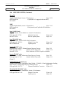
2-1
2.1
2.2
2.3
2.4
2.5
Input Data Range
Output Data Range
Dimensions
Power Requirements
Output Data
2.5.1 Serial Output Data Parameters
Limitations
2.6.1 Warm-up Time
2.6.2 Supplemental Equipment
2.6.3 Static/Pitot Source Error Correction (SSEC/PSEC)
2.6.4 SSEC/PSEC Listing
2.6.4 SSEC/PSEC Listing (Continued)
2.6.4 SSEC/PSEC Listing (Continued)
2.6.4 SSEC/PSEC Listing (Continued)
2-1
2-1
2-1
2-1
2-2
2-2
2-3
2-3
2-3
2-3
2-4
2-5
2-6
2-7
Part Numbering Scheme
2-8
2.6
2.7
3.0
CERTIFICATION
3-1
4.0
PLACING AN ORDER
4-1
IM2803
FILE: IM2803MG.DOC, DIR: 912802
Shadin Avionics
INSTALLATION MANUAL
DIGIDATA
P/N 912802-A, 912802-03A, 912802-03A-G
Rev: M
SECTION
NO.
5.0
DESCRIPTION
Page: ii of v
PAGE
INSTALLATION PROCEDURE
5-1
5.1
5.2
5.3
5.4
5.5
5.6
5.7
5.8
5.9
5.10
5-1
5-1
5-1
5-2
5-3
5-4
5-5
5-6
5-6
5-6
General
DigiData Panel Location Selection
Mounting the DigiData
Mounting the OAT Probe
Connection to the Fuel Flow Sensor
Connection to the Heading Source
Connection to the Pitot and Static Lines
Connection to the Navigation Management System
Connection to the DC Power Buss
Post Installation Checkout
6.0
BASIC OPERATING INSTRUCTIONS
6-1
7.0
INITIALIZATION
7-1
8.0
MAJOR COMPONENTS OF THE SYSTEM
8-1
9.0
CONFIGURING THE DIGIDATA
9-1
9.1
9-1
9-2
9-3
9-4
9-5
Configuring Manually (Loop-back)
Table of Configuration Selections
Table 1. Analog K-Factor Settings Table
Table 2. SSEC and PSEC Selections
Table 3. Navigational Receiver Types
IM2803
FILE: IM2803MG.DOC, DIR: 912802
Shadin Avionics
INSTALLATION MANUAL
DIGIDATA
P/N 912802-A, 912802-03A, 912802-03A-G
Rev: M
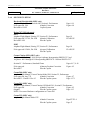
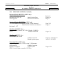
10.0
Drawing No.
4005-483
Page: iii of v
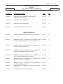
INSTALLATION DRAWINGS AND INSTALL KIT PARTS LISTS
Description/Part Number
Installation, DigiData, Hi/Lo Freq. Input TTL FF
P/N 912802, Page 1 of 2
DATE
REV
05/06/99
E
4005-479
Installation, DigiData, Hi/Lo Freq. Input TTL FF
P/N 912802, Page 2 of 2
07/30/98
D
4005-546
Installation, DigiData, Analog FF Option
P/N 912802-03, Page 1 of 2
05/06/99
D
4005-548
Installation, DigiData, Analog FF Option
P/N 912802-03, Page 2 of 2
07/30/98
C
4028-A23
Installation, DigiData, Analog FF, Grey Face
P/N 912802-03-G, Page 1 of 2
05/6/99
A
4028-A24
Installation, DigiData, Analog FF, Grey Face
P/N 912802-03-G, Page 2 of 2
07/30/98
–
4070-005
Installation, Serial to Argus 5000/7000 Converter
P/N 937000-03
02/14/05
B
4005-642
Installation, Sine/Squarewave Converter
P/N 631201
03/03/03
A
4028-005
Installation, OAT Probe Assembly Kit, P/N 681201-1
02/14/05
C
N/A
Parts List, OAT Probe Assembly Kit
P/N 681201-1
Parts List, Install Kit, DigiData,
P/N IK9128
04/06/07
H
07/23/98
–
N/A
4028-A19
Installation Wiring, DigiData to NAV Receivers
W/RS-232
03/03/03
B
4028-A20
Installation Wiring, DigiData and Shadin Converter to
Eventide Argus
07/30/98
–
4028-A21
Installation Wiring, DigiData to NAV Receivers
W/RS-422, RS-485
03/03/03
A
IM2803
FILE: IM2803MG.DOC, DIR: 912802
Shadin Avionics
INSTALLATION MANUAL
DIGIDATA
P/N 912802-A, 912802-03A, 912802-03A-G
Rev: M
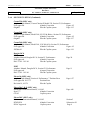
10.0
Page: iv of v
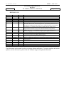
INSTALLATION DRAWINGS AND INSTALL KIT PARTS LISTS (continued)
Drawing No.
Description/Part Number
DATE
REV
4028-A22
Installation Wiring, DigiData, Sine to Digital FF
Converter, Various Aircraft
03/11/03
A
4028-207
Installation Wiring, DigiData FF
07/30/98
G
4028-373
Installation Wiring, DigiData FF
03/11/03
E
4028-716
Installation Wiring, Loop Back Harness
03/11/96
–
AIRCRAFT SPECIFIC
4028-820
Installation Wiring, DigiData with Analog FF Indicators
03/11/03
B
4028-936
Installation Wiring, F/ADC200, 2000 or DigiData with
DC FF to Cessna Citation 500, 501, 550, S550, 551, 552
02/14/05
A
4028-937
Installation Wiring, F/ADC200, 2000 or DigiData with
DC FF to Cessna Citation 525 Jet
02/14/05
A
4028-938
Installation Wiring, F/ADC200, 2000 or DigiData with
Digital FF to BomBardier Learjet 24, 25D
01/17/05
A
4028-940
Installation Wiring, F/ADC200, 2000 or DigiData with
DC FF to Raytheon Beechjet 400A Aircraft
02/14/05
A
4028-941
Installation Wiring, F/ADC200, 2000 or DigiData with
DC FF to Westwind 1124 Models
02/14/05
A
4028-A29
Installation Wiring, F/ADC200, 2000 or DigiData with
DC FF Piper Cheyenne PA31T
01/17/05
C
4028-E68
Installation Wiring, Digidata Freq. Input, FF TransducerConverters
03/11/03
–
4028-E69
Installation Wiring, Connectors, Digidata
03/11/03
–
IM2803
FILE: IM2803MG.DOC, DIR: 912802
Shadin Avionics
INSTALLATION MANUAL
DIGIDATA
P/N 912802-A, 912802-03A, 912802-03A-G
Rev: M
Page: v of v
REVISION LOG
REV.
A
B
C
D
E
DATE
10/21/93
09/09/94
08/07/95
05/09/96
08/07/98
06/10/99
APP’D
RR
SES
KCL
KCL
KCL
EDJ
F
01/31/00
EDJ
G
09/12/00
KCL
H
J
09/12/00
04/18/03
KCL
EDJ
K
L
M
02/25/05
01/05/06
05/20/08
ZK
CB
ZK
CHANGE
Release
Miscellaneous updates
Miscellaneous updates
Miscellaneous updates
Format change, SSEC listing, software configuration update, new installation DWGs
Update Analog K-Factor table, correct SSEC/PSEC list and alphabetize, correct
SSEC/PSEC selection table, insert drawing 4028-716, replace drawings 4028-A29, 4005483, 4028-546 and 4028-A23 with current revision. Update descriptions in drawings 4005642 and 4028-373. Formatting changes made to manual reflecting current revision.
Add Garmin, FormatG, to page 9.3 Loran Output Type list. Page iv changed due to adding
Ragen Indicator/Transmitter to page 10-26, 4028-A29 installation wiring drawing.
Change page iii, 5-2, and 8-1 OAT probe to P/N 681201A-1, changed page 2-1 PALT to
50000 ft, change page 3-1 environmental categories, replace pages 10-10 and 10-11.
Update: Title page, pages i through v, page 5-1, page 5-4 and Drawing No 4028-A19.
Revised Section 9 to include Configuration Selection procedure and Tables. OAT probe
correction code selection was added. Updated Section 2.2.
Changed Company name. Updated Installation Dwg Section 10.
Updated Company Logo, Section 5.2, Section 2.2.
Added A to Digidata part numbers due to software change and RTCA/DO-178B Level D.
Changed Page 2-1.
The information in this manual is subject to change without notification. To ensure complete and current
updates, note the Revision Log above and call Technical Support for updated information.
IM2803
IM2803MG.DOC., DIR. 912802
Shadin Avionics
INSTALLATION MANUAL
DIGIDATA
P/N 912802-A, 912802-03A, 912802-03A-G
Rev: M
1.0
OVERVIEW
1.1
The Manual
Page: 1-1
This manual is designed to facilitate the installation of the Shadin DigiData (FUEL/AIRDATA
COMPUTER/INDICATOR).
1.2
Product Information
The Shadin DigiData system is designed to provide a combined source of fuel and airdata. The
data can be viewed on the DigiData, a navigational receiver or both. Listed below are the
navigational systems that the DigiData has been designed to be compatible with. Note that not all
navigational systems are capable of receiving fuel and airdata information from the DigiData but
provide data necessary for some fuel management and wind calculations.
Receives Serial Data from:
ARNAV
STAR 5000
FMS 7000
R5000
Trimble
2000/2000A
2100/3000
3100/2101
Bendix King
KLN90
KLN90A
KLN90B
KLN89/89B
KLN900
Garmin
150, 155, 155XL, 165
230, 230XL
300, 300XL
Northstar
M1, M2, M3
60/600 GPS
IIMorrow
611, 612, 618
NMS 2001
800, 820, 360
GX50, 55, 60
Transmits Serial Data to:
ARNAV
Bendix/King
Trimble
Garmin
IImorrow
Note: To find out which particular receiver
models have airdata receive capability,
contact the manufacturers.
IM2803
IM2803MG.DOC., DIR. 912802
Shadin Avionics
INSTALLATION MANUAL
DIGIDATA
P/N 912802-A, 912802-03A, 912802-03A-G
Rev: M
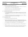
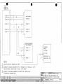
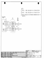
1.3
Page: 1-2
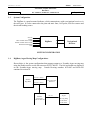
System Configuration
The DigiData is a panel mounted indicator, which communicates with a navigational receiver via
the serial port. It is also connected to the pitot and static lines, OAT probe, fuel flow sensors and
the aircraft heading source.
STATIC
PITOT
LEFT ENGINE FUEL FLOW
RIGHT ENGINE FUEL FLOW
MAGNETIC HEADING
OAT
DigiData
Navigational
Receiver
SYSTEM CONFIGURATION
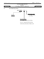
1.4
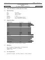
DigiData, Argus Moving Map Configurations.
Shown below is the system configuration that supports output to a Eventide Argus moving map
using the Shadin serial to serial data converter P/N 937000-03. The fuel and airdata are displayed
on the Eventide-Argus moving map. Consult Drawing numbers 4070-005 and 4028-A20
contained in section 10.
RS-232 or RS422
Shadin
DigiData
RS-232 or RS422
Shadin
Converter
P/N 937000-03
Navigational
Receiver
RS-232
Eventide
Argus
M oving M ap
P/N 5000
P/N 7000
IM2803
IM2803MG.DOC., DIR. 912802
Shadin Avionics
INSTALLATION MANUAL
DIGIDATA
P/N 912802-A, 912802-03A, 912802-03A-G
Rev: M
2.0
FUEL AND AIRDATA SYSTEM SPECIFICATIONS
2.1
Input Data Range
Pitot
Static
OAT
Heading
Fuel Flow
K Factor
2.2
20 to 350 kt.
-1000 to 50,000 ft.
-60°C to, +60°C
0 - 360°
1 to 450 GPH Range Selected
500 to 130000 PPG Continuous
Output Data Range
PARAMETER
IAS
P.ALT
P.ALT
P.ALT
P.ALT
P.ALT
P.ALT
P.ALT
P.ALT
P.ALT
OAT
HEADING
IVS
TAS
MACH
WIND SPEED
WIND DIRECTION
FUEL FLOW
Accuracy *
±1 Kt
±25 ft
±30 ft
±35 ft
±40 ft
±45 ft
±50 ft
±75 ft
±100 ft
±125 ft
±1°C
±1°
±40 ft
±2 Kts
±.01
±5 Kt
±10°
±2%
RANGE
20 to 350 Kt.
-1000 to 5000 ft
8000 ft
11000 ft
14000 ft
17000 ft
20000 ft
30000 ft
40000 ft
50000 ft
-60°C to +60°C
0 - 360 degrees
±10,000 ft/min.
20 - 600 kt.
.2 - .95
5 - 360 Kt.
0 - 360 degrees
1-450 GPH
* Listed accuracy’s are after warm-up is complete.
2.3
Dimensions
Size: 7.6" Deep x 3.3" Square (Face) x 3.14" Round (Can).
Mounting hole: Standard 3 1/8" Diameter.
Weight: 1.1 lbs.
2.4
Power Requirements
System Power required: 28 VDC @ 1300 mA 14 VDC @ 900 mA
Page: 2-1
IM2803
IM2803MG.DOC., DIR. 912802
Shadin Avionics
INSTALLATION MANUAL
DIGIDATA
P/N 912802-A, 912802-03A, 912802-03A-G
Rev: M
2.5
Page: 2-2
Output Data
Electric Format: RS-422 or RS-232
2.5.1
Serial Output Data Parameters
Fuel Group
L. ENG. Fuel Flow
R. ENG. Fuel Flow
Fuel Used Total
Total Fuel Used
Fuel Used L. ENG.
Fuel Used R. ENG.
Fuel Remaining
NM/Fuel Unit (ground)
Fuel to Destination
Fuel at Destination
Airdata Group
Pressure Altitude (PA)
Density Altitude (DA)
Barometric Corrected Altitude (BA)
Indicated Air Speed (IAS)
True Air Speed (TAS)
Vertical Speed (IVS)
True Air Temperature (TAT)
Outside Air Temperature (OAT)
Drift Angle
Magnetic Heading (HDG)
Rate of Turn (ROT)
MACH Number
Wind Direction and Speed
Note: Not all parameters will be available to all navigational receivers. Contact the manufacturer
for display capabilities.
IM2803
IM2803MG.DOC., DIR. 912802
Shadin Avionics
INSTALLATION MANUAL
DIGIDATA
P/N 912802-A, 912802-03A, 912802-03A-G
Rev: M
2.6
Limitations
2.6.1
Warm-up time
The DigiData requires a warm-up time that varies with ambient temperature:
70°C ambient
15°C ambient
-20°C ambient
-40°C ambient
Page: 2-3
5 minutes warm-up required
10 minutes warm-up required
15 minutes warm-up required
20 minutes warm-up required
If the DigiData has been configured for a fuel flow delay, fuel flow and thus fuel used information
shall be unavailable at startup for the duration of the selected delay.
2.6.2
Supplemental Equipment
All Shadin F/ADC(s) and ADC(s) (including the DigiData) are not designed to replace factory
installed airdata fuel flow systems or other gauges. They are not intended to be used as a primary
system to drive altimeters or airspeed indicators. The F/ADC fuel section is not a fuel quantity
system and therefore reports only what was manually entered by the operator.
2.6.3
Static Source Error Correction (SSEC),
Pitot Source Error Correction (PSEC)
For certain models of aircraft, the Fuel/Airdata System will make corrections to pressure altitude
by compensating for static source error. For some of these models, the Fuel/Airdata System will
make corrections to indicated airspeed by compensating for pitot source error.
The System does not provide true and absolute readings for all circumstances. It makes no
altitude corrections when the uncorrected IAS is below 100 knots, and it makes no airspeed
corrections when the uncorrected IAS is below 150 knots. It does not account for other factors,
such as the current useful weight, that contribute to static source error and pitot source error.
Rather, the Fuel/Airdata System performs calculations based solely on indicated airspeed and
pressure altitude. The SSEC / PSEC corrections were derived from specific aircraft data referred
to in section 2.6.4. To configure the Shadin DigiData for a specific aircraft model refer to section
9.
IM2803
IM2803MG.DOC., DIR. 912802
Shadin Avionics
INSTALLATION MANUAL
DIGIDATA
P/N 912802-A, 912802-03A, 912802-03A-G
Rev: M
Page: 2-4
2.6.4 SSEC/PSEC LISTING
Beechcraft Beechjet-400 (SSEC only)
Airplane Flight Manual, BeechJet 400, Section 6, Performance
FAA approved 1/86
Altitude Correction
Revision A9 14/92
Copilot System
Boeing 707-321B Advanced
SSEC
Airplane Flight Manual, Boeing 707, Section IV, Performance
FAA approved 3/27/69, D6-1588
Altitude Calibration
Revision 2/4/69
Pilot & Copilot
PSEC
Airplane Flight Manual, Boeing 707, Section IV, Performance
FAA approved 9/20/66, D6-1588
Airspeed Calibration
Pilot & Copilot
Page 6-14
Figure 6-8
Page 19
FLAPS UP
Page 18
FLAPS UP
Cessna Citation S550 (SSEC only)
Airplanes -0115 through -0160 Except Airplanes Incorporating SBS550-32-7 and
Airplanes -0001 through-0114 Incorporating SBS550-32-1 but not SBS550-32-7.
Section IV - Performance, Standard Charts
FAA approved
Altimeter Position Correction
Revision 37
Pilot & Copilot
Pages 4-17, 4-18
Figure 4-5
Cessna 500 (SSEC only)
Airplane Flight Manual, Cessna/Citation Model 500, Section IV, Performance
FAA approved Aug 7/74
Altitude Correction
Figure 4-7
Revision 53 - Dated 11 Dec 85
Pilot & Copilot system
Page 4-17.1
Cessna 501 (SSEC only)
Airplane Flight Manual, Cessna/Citation I SP Model 501, Section IV, Performance
FAA approved
Altitude Correction
Figure 4-5
Original
Pilot & Copilot system
Page 4-15
NOTE: Uses same Hardware configuration as Cessna 500
Cessna 525 (SSEC only)
Airplane Flight Manual Model 525
Altitude Correction
Pilot & Copilot system
Rept FT525-4
Page 47
IM2803
IM2803MG.DOC., DIR. 912802
Shadin Avionics
INSTALLATION MANUAL
DIGIDATA
Rev: M
P/N 912802-A, 912802-03A, 912802-03A-G
Page: 2-5
2.6.4 SSEC/PSEC LISTING (Continued)
Cessna 550 (SSEC only)
Airplane Flight Manual, Cessna/Citation II Model 550, Section IV, Performance
FAA approved
Altitude Correction
Figure 4-5
Original
Pilot & Copilot system
Page 4-15
Cessna 560 (SSEC only)
Airplane Flight Manual, Model 560, S/N 259 & Below, Section IV, Performance
FAA approved
Altitude Correction
Figure 4-5
Original
Pilot & Copilot system
Page 4-17
Cessna 560 (SSEC only)
Airplane Flight Manual, Model 560 , S/N 260 & Up, Section IV, Performance
FAA approved
Altitude Correction
Figure 4-5
56FMA-00
Pilot & Copilot system
Page 4-19
Douglas DC-8
SSEC
Airplane Manual, Douglas DC-8, Section IV, Performance
FAA approved
Altitude Correction
DAC-33161 10/1/66
Pilot & Copilot system
PSEC
Airplane Manual, Douglas DC-8, Section IV, Performance
FAA approved
Airspeed Correction
DAC-33161 10/1/66
Pilot & Copilot system
Falcon 10 (SSEC only)
Airplane Flight Manual, Section 6. Performance, 7 Position Error
FAA approved 10/17/73
Position Error
Revision 14, 6/6/78
Pilot & Copilot
Falcon 20-C, D, E (SSEC only)
Maintenance Instruction Manual, 34-18-03
Sept 1/77
Altitude Correction
CS-143
Copilot system
Falcon 20-F (SSEC only)
Maintenance Instruction Manual, 34-18-03
DTM30528
Altitude Correction
DGAC Approved
Copilot system
Page 20
Page 11
Page 6-27
Page A48
Section 5
Subsection 20
Page 4
IM2803
IM2803MG.DOC., DIR. 912802
Shadin Avionics
INSTALLATION MANUAL
DIGIDATA
Rev: M
P/N 912802-A, 912802-03A, 912802-03A-G
Page: 2-6
2.6.4 SSEC/PSEC LISTING (Continued)
Falcon 50
SSEC
Airplane Flight Manual, Section 5. Performance
Page 5.25.2
DGAC approved
Copilot (for A/C equipped with one ADC)
Revision 24
PSEC
Airplane Flight Manual, Section 5. Performance
Page 5.25.2
DGAC approved
Pilot (normal) and Copilot MACH Indicators
Revision 24
Lear 24 (SSEC only)
Airplane Manual, LearJet Model 24, Section IV, Performance
FAA approved 3/17/66
Altitude Correction
Revised 7/19/68
Pilot & Copilot system
Figure 4-10
Page 4-16
Lear 25D (SSEC only)
Airplane Manual, LearJet 25D/F AFM, Performance
FAA approved 10/14/86
Altitude Correction
FM-018 Release A
Copilot system
Figure 5-10
Page 5-18
Learjet 35 (SSEC only)
Flight Manual, LearJet 35, Normal System, Flaps up, Gear up
Page 5-18
FAA approved, 4/30/76
Altitude Position Correction
Figure 5-10
Reissued 2/25/81
Pilot’s Altimeter- STBY & Copilot’s Altimeter
Learjet 55 (SSEC only)
Gates Learjet 55, APM, Performance Data, Flaps up, Gear up
FAA approved, 3-17-81
Altitude Position Correction
Change 13
Page 5-20
Figure 5-11
Lockheed Jetstar II (SSEC only)
Airplane Flight Manual, Performance Data, Weight = 32,000 Lb., Clean Configuration: Leading
Edge Flaps up, Trailing Edge Flaps up, Landing Gear up
Page 4-25
FAA approved, 12/14/76
Altimeter Installation Correction
Figure 4-15
Mitsubishi MU-300 (SSEC only)
Airplane Flight Manual, Diamond IA, Section 6, Performance
FAA approved Jan 11/84
Altitude Correction
Copilot system
Figure 6-8
Page 6-20
IM2803
IM2803MG.DOC., DIR. 912802
Shadin Avionics
INSTALLATION MANUAL
DIGIDATA
Rev: M
P/N 912802-A, 912802-03A, 912802-03A-G
Page: 2-7
2.6.4 SSEC/PSEC LISTING (Continued)
Raytheon Hawker HS125-3A (SSEC only)
Airplane Manual,
Document No. H.S.1.10
Static Position Error
CAA Approved
Correction to Altimeter
Raytheon Hawker HS125-700A (SSEC only)
125 Crew Manual, First Officer, Section 2, Flaps Retracted
Static Position Correction to Altimeter
Revision: G, 4/77
Sabreliner 60 (SSEC only)
Sabreliner Pilot’s Manual, SR 75-064, Weight = 16,000 Lb.
9/1/76
Altitude Calibration
Section 5
Figure 5-4
Page 13
Page 2-30
Figure 6
Figure 7-2
Sabreliner 65 (SSEC only)
Pilots Manual, SR-78-028
Altitude Correction
Pilot & Copilot system
Westwind 1124A (SSEC only)
Airplane Flight Manual, 1124A, Section V, Performance
CAA approved
Altitude Correction
Figures 5-13, Flaps 0
Copilot system
NOTE: Gross Weight averaged at 18,750 lbs.
Figures 7-1 through 7-5
265-65-7-31,32A,33
Pages V-25
IM2803
IM2803MG.DOC., DIR. 912802
Shadin Avionics
INSTALLATION MANUAL
DIGIDATA
P/N 912802-A, 912802-03A, 912802-03A-G
Rev: M
2.7
Part Numbering Scheme
P/N 912802 – XX – Y
Display Face Color
Y= “Blank”, Black
Y= G, Gray
DigiData
Fuel Sensor Type
XX= “Blank”, DIGITAL Fuel Flow
XX= 03, ANALOG (DC) Fuel Flow
XXX=XXA, RTCA/DO-178B Level D
Page: 2-8
IM2803
IM2803MG.DOC., DIR. 912802
Shadin Avionics
INSTALLATION MANUAL
DIGIDATA
P/N 912802-A, 912802-03A, 912802-03A-G
Rev: M
3.0
CERTIFICATION
TSO-C106, TSO-C44a
Environmental Categories RTCA/DO-160B
Temp. ALT
Temp. Variation
Humidity
Shock & Vibration
Magnetic Effect
Power Input
Voltage Spike
AF Conducted Susceptibility
Induced Signal Susceptibility
RF Susceptibility
RF Emission
D1
B
A
P,K,S
B
B
B
B
B
A
B
Page: 3-1
IM2803
IM2803MG.DOC., DIR. 912802
Shadin Avionics
INSTALLATION MANUAL
DIGIDATA
P/N 912802-A, 912802-03A, 912802-03A-G
Rev: M
4.0
Page: 4-1
PLACING AN ORDER
Please know the aircraft year and model number, its serial number, and the engine make and
model number when you call to place orders. Information on the fuel flow system previously
installed in the aircraft and any communication interface (RS-232 or RS-422) information may
also prove useful.
We may request a wiring diagram of the aircraft fuel flow system and transducer and/or K-factors.
IM2803
IM2803MG.DOC., DIR. 912802
Shadin Avionics
INSTALLATION MANUAL
DIGIDATA
P/N 912802-A, 912802-03A, 912802-03A-G
Rev: M
5.0
INSTALLATION PROCEDURE
5.1
General
Page: 5-1
All work must conform to AC43.13-1B or later.
5.2
DigiData Panel Location Selection
The DigiData should be panel mounted in a dry, temperature stable location with enough distance
from motors, pulse generating equipment, relays and cables carrying high DC or AC current.
It may be installed in a non-pressurized and non-controlled temperature location. In considering
the location, keep in mind that the DigiData requires signals from the fuel flow, the OAT probe,
heading system (Arinc 407) and the pitot and static lines.
Remember to provide ample space behind the DigiData for the mating connectors and pitot and
static lines.
5.3
Mounting the DigiData
Depending on the DigiData part number mount per Drawing 4005-483 and 4005-479, 4005-546
and 4005-548 or 4028-A23 and 4028-A24 found in section 10. Make sure that the DigiData is not
the lowest point in the pitot and static system, to reduce the chances of collecting moisture or
water in it. Form a water trap, if necessary.
IM2803
IM2803MG.DOC., DIR. 912802
Shadin Avionics
INSTALLATION MANUAL
DIGIDATA
P/N 912802-A, 912802-03A, 912802-03A-G
Rev: M
5.4
Page: 5-2
Mounting the OAT Probe
1.
Refer to Drawing 4028-005 and OAT Probe Assy Kit 681201-1. Use the supplied stiffener to
support the probe. Keep the probe away from transmitting antennas and static ports to avoid
interference.
2.
Refer to Drawing 4028-207: +5V is supplied to the OAT probe from (red wire) P3:8. The
OAT signal is the white (or black) wire from P3:9.
3.
The sun shield must be installed for proper indication of OAT.
4.
For single engine installation, avoid mounting the OAT probe on the belly of the aircraft to
avoid erroneous reading due to the presence of hot exhaust gases.
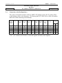
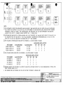
5. Below is a OAT °C to mirco-ampere conversion chart. The amperage can be measured by
connecting an ammeter in series between the signal wire of the OAT probe and the DigiData.
This information is provided for trouble shooting purposes only.
OAT ºC
-60
-50
-40
-30
Input µA
213
223
233
243
OAT ºC
-20
-10
0
+10
Input µA
253
263
273
283
OAT ºC
+20
+30
+40
+50
Input µA
293
303
313
323
1°C = 1 μA
IM2803
IM2803MG.DOC., DIR. 912802
Shadin Avionics
INSTALLATION MANUAL
DIGIDATA
P/N 912802-A, 912802-03A, 912802-03A-G
Rev: M
5.5
Page: 5-3
Connection to the Fuel Flow Sensor
1.
If the aircraft is not equipped with a fuel flow source, refer to the STC covering the
installation of the fuel flow transducer on the engine.
2.
When connecting to any fuel transducer, Shadin recommends using a 3 conductor, 22 gauge,
shielded wire with the shield terminated at the DigiData only.
3.
Note that for single engines all fuel flow types should use left side inputs only.
4.
*Install the transducers according to the engine STC. Use Drawing 4028-207 (Freq. Option)
to connect the fuel flow transducer to the DigiData.
5.
*If the aircraft is equipped with a digital fuel flow transducer (P/N 680501), use Drawing
4028-207 and the STC drawing covering the installation of the fuel flow transducer in the fuel
line.
6.
*If the aircraft is equipped with an existing digital fuel flow transducer (P/N 6605XX), use
Drawing 4028-207 and the STC drawing covering the interconnection of the fuel totalizer to
the existing fuel flow system.
7.
Before hooking to an existing fuel system in a turbine or jet application, consult all
installation drawings contained in this manual.
8.
*If the aircraft is equipped with a Analog (DC) fuel flow system, use Drawing 4005-546,
4005-548, 4028-A23, 4028-A24 and 4028-207.
9.
*If the aircraft is equipped with a sine wave pickup coil type of fuel flow transducer, use
Drawing 4028-373 (Sine Wave Signal). Use the converter, SHA P/N 631201 (Drawing 4005642).
10. Make sure that the system is initialized with the proper K factor. Consult the DigiData
Operating Manual OM2802 and section 9.1 of this manual for setup.
* Consult section 10 of this manual for specific aircraft installation wiring drawings.
IM2803
IM2803MG.DOC., DIR. 912802
Shadin Avionics
INSTALLATION MANUAL
DIGIDATA
P/N 912802-A, 912802-03A, 912802-03A-G
Rev: M
5.6
Page: 5-4
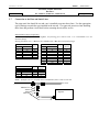
Connection to the Heading Source
The system is designed to interface with any ARINC-407 heading system (X,Y,Z) with no effect
on the heading system or the bootstrap. Use Drawing 4005-479, 4005-548, or 4028-A24 and the
table below when connecting to the bootstrap.
XYZ
Heading
ARINC
407
DigiData
P3
X
Y
Z
H
C
5
4
7
6
7
Collins
328A-2A
2P1
11
4
3
26
22
Collins
HSI331A
P1
S
T
U
V
W
Collins
MCS 65
P1
25
40
24
6
5
Collins
328A-5
32
22
12
53
57
King
KI525A
P2
s
v
t
r
u
King
KSG105
P1
t
p
k
c
f
Sperry
Gyrosyn
Comp.
P1
Sigma-Tek
DG
L
M
K
H
J
A
B
D
E
H
Sandel
SN3308
P2
The C (AC common) and Z leads are connected together internally in the DigiData.
P1
25
6
4
4
4
IM2803
IM2803MG.DOC., DIR. 912802
Shadin Avionics
INSTALLATION MANUAL
DIGIDATA
P/N 912802-A, 912802-03A, 912802-03A-G
Rev: M
5.7
Page: 5-5
Connection to the Pitot and Static Lines
The pitot static line should be cut and a tee is installed to tap into these lines. Use the appropriate
type of fittings to match the type installed in the aircraft. Use approved practices when installing
these lines and perform a leak check before returning the aircraft to service.
PITOT/STATIC adapter helpful hints
To make an adapter for the Shadin DigiData, the following parts could be used. It is recommended to use all
aluminum fittings.
Existing Pitot/Static lines
AN910-1D
AN816-2D
#2 Hose(with female fittings)
AN910 DASH NUMBER
BRASS
ALUM. ALLOY
-1
-2
-3
-4
-6
-8
-1D
-2D
-3D
-4D
-6D
-8D
MS20825 TEE
STEEL
ALUM. ALLOY
-2
-3
-4
-5
-2D
-3D
-4D
-5D
PIPE
SIZE
AN816 DASH NUMBER
STEEL ALUM. ALLOY
1/8”
1/4”
3/8”
1/2”
3/4”
1”
-2
-3
-4
-5
-6
-8
-10
-12
-16
TUBE
O. D.
PIPE
THREAD
1/8”
3/16”
1/4”
5/16”
1/8”
1/8”
1/8”
1/8”
-2D
-3D
-4D
-5D
-6D
-8D
-10D
-12D
-16D
TUBE
O. D.
PIPE
THREAD
1/8”
3/16”
1/4”
5/16”
3/8”
1/2”
5/8”
3/4”
1”
1/8”
1/8”
1/8”
1/8”
1/4”
3/8”
1/2”
3/4”
1”
HOSE: Stratoflex 193-2 or Aeroquip 306-2 with MS27404 (P/N 311-2D) on each end.
Air source
MS20825 Tee
AN910
AN816
MS27404
DigiData
IM2803
IM2803MG.DOC., DIR. 912802
Shadin Avionics
INSTALLATION MANUAL
DIGIDATA
P/N 912802-A, 912802-03A, 912802-03A-G
Rev: M
5.8
5.9
5.10
Page: 5-6
Connection to the Navigation Management System
1.
Use the appropriate installation wiring diagram (4028-A19 or 4028-A21) to connect the
DigiData Connector P1 to the navigation management system.
2.
Keep the cables away from power cables, DME and transponder cables.
3.
Refer to the specific Nav Receiver Installation Manuals for details.
Connection to the DC Power buss
1.
Consult Installation Drawing P/N 912802 for a DigiData with digital fuel flow, P/N 91280203 for a DigiData with DC fuel flow, or P/N 912802-03-G for a DigiData with DC fuel flow
and a gray face.
2.
Install a 2 amp. circuit breaker between P1:1 of the DigiData and the power buss. Mark the
circuit breaker by engraving, painting or other approved method.
Post Installation Checkout
1.
The pitot and static system must be checked for leaks.
2.
Operate the Navigation Management System; select the altitude and airspeed pages. Use a
static and pitot test system to verify the accuracy. Compare the pressure altitude and
indicated air speed between the DigiData and Navigation Management System pages.
3.
Select heading page. Slew compass through 360°. The error should be within ±1°.
4.
Select the OAT page. Compare to the reported ambient temperature. The error should be ±1
½ °C.
5.
Run the engines and select the fuel flow page. Compare the fuel flow readout with the engine
manufacturer's fuel flow charts under the ambient temperature and pressure conditions.
IM2803
IM2803MG.DOC., DIR. 912802
Shadin Avionics
INSTALLATION MANUAL
DIGIDATA
P/N 912802-A, 912802-03A, 912802-03A-G
Rev: M
6.0
Page: 6-1
BASIC OPERATING INSTRUCTIONS
1.
For a complete set of operating instructions consult the DigiData Operating Manual P/N
OM2802.
2.
Power the DigiData and the Navigation Management System.
3.
After the warm-up period density altitude and PALT are available. IAS will be available but
will be out of range until actual airspeed is available. Winds aloft will be available if the IAS
is greater than 40 Kts and magnetic heading is within 40° of magnetic track.
4.
Fuel Flow, Fuel Used, Fuel Remaining, Heading and OAT will be available after power-up.
5.
Refer to the specific Nav Receiver Operator's Manual for page selection of various data.
IM2803
IM2803MG.DOC., DIR. 912802
Shadin Avionics
INSTALLATION MANUAL
DIGIDATA
P/N 912802-A, 912802-03A, 912802-03A-G
Rev: M
7.0
Page: 7-1
INITIALIZATION
1. The DigiData is preprogrammed (Initialized) prior to shipping. If changes are required in the
DigiData setup, use Drawing 4028-716 to create a configuration harness (“Loop-Back”
harness). Refer to the Operating Manual P/N OM2802 and the Tables listed in section 9 of
this manual for programming instructions. Before making changes it is advisable to record the
current settings.
2. Refer to the Navigational Receiver manual for serial port setup. It is necessary to have both
the DigiData and the Receiver configured correctly.
3. If you need to change the K-factor and or Offset for P/N (s) 912802-03A or 912802-03A-G
refer to the “DigiData Analog Fuel Flow Chart” Table 1 contained in Section 9.1.
IM2803
IM2803MG.DOC., DIR. 912802
Shadin Avionics
INSTALLATION MANUAL
DIGIDATA
Rev: M
8.0
P/N 912802-A, 912802-03A, 912802-03A-G
MAJOR COMPONENTS OF THE SYSTEM
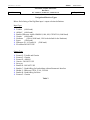
1. DigiData.
2. Outside Air Temperature Probe Assembly, SHA P/N 681201-1
3. Navigational Receiver
Page: 8-1
IM2803
IM2803MG.DOC., DIR. 912802
Shadin Avionics
INSTALLATION MANUAL
1
DIGIDATA
Rev: M
9.0
P/N 912802-A, 912802-03A, 912802-03A-G
Page: 9-1
CONFIGURING THE DIGIDATA
The DigiData Fuel Airdata Computer comes configured from the factory for a particular
installation. The procedure contained in this Installation Manual is for software versions 93.10.75
and above.
9.1
Configuring Manually (Loop-back)
The unit is powered using the loop-back harness (consult drawing number 4028-716 contained in
section 10). The purpose of the loop-back harness is to tie the RS-232 transmit and receive ports
together. This allows the software, when the unit is powered on, to allow configuration of the unit
through the front panel switches and displays.
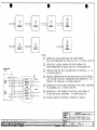
To enter the configuration mode:
1. Connect the special configuration harness to the DigiData and connect to power source.
2. Set the rotary switch knob to Airdata position and apply power to the unit.
3. After the unit has completed the Start Up self test mode, press and hold the TEST/ENTER
button until the DigiData enters the test mode. At the end of the normal test mode displays,
the unit will display “System Setup” and enter the configuration mode.
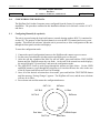
4. The ADD/FULL switch is used to page through the options per figure below. Use the USED
and REM buttons to scroll through the selections (or to increase/decrease the value in the case
of the K-Factors and Offsets and Low Fuel Warning).
5. Once all of the desired selections have been made, press and hold the TEST/ENTER button
until the message “Saving Changes” appears. The DigiData will reset, and the new selections
will now be in effect.
6. Power down unit and disconnect the configuration harness.
OAT C=0
LKFactor
OAT B=0
L Offset
OAT A=0
RKFactor
ADD
FULL
End. Warn
PALTCorr
LORAN Output
Baud Rate
IM2803
IM2803MG.DOC., DIR. 912802
Shadin Avionics
INSTALLATION MANUAL
DIGIDATA
Rev: M
P/N 912802-A, 912802-03A, 912802-03A-G
Page: 9-2
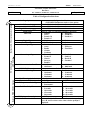
Table of Configuration Selections
Airdata Page Options
Rotate to OAT Correction Code Option
Left K-Factor (in ppg)
Left Offset
Right K-Factor (in ppg)
Right Offset
Fuel Units
Engine Type
Fuel Filter Type
Loran Input Type
Rotate to PSSEC/SSEC Option
FULL Switch →
ADD Switch ←
Loran Output Type
Serial Communication Baud Rate
SSEC/PSEC Corrections
Endurance Warning Time
Low Fuel Warning (in fuel units)
Barometric Preference
OAT Temperature Probe Types
Fuel Flow Delay Time
ARINC Output Status Options
OAT Correction Codes
Configuration Selections
(USED/REM Pushbuttons used to select option)
Refer to Table 1 or fuel flow transducer data sheet.
Refer to Table 1 or fuel flow transducer data sheet.
Refer to Table 1 or fuel flow transducer data sheet.
Refer to Table 1 or fuel flow transducer data sheet.
1. Gallons
5. Kilogram
2. Liters
6. Pounds 6.5
3. Pounds 5.8
7. Pounds 6.3
4. Pounds 6.7
1. Single
2. Twin
1. Normal (Injector)
2. Carburetor
1. Trimble
6. Foster
2. Arnav
7. IIMorrow
3. Bendix
8. FlowMeter
4. Garmin
5. Northstar
1. Format Z
6. Bendix D
2. Format X
7. Shadin S
3. Generic
8. Bendix B
4. Surveyor
9. Garmin G
5. Bendix C
1. 9600 baud
3. 2400 baud
2. 1200 baud
4. 4800 baud
Refer to Table 2
1. 45 minutes
5. 25 minutes
2. 10 minutes
6. 30 minutes
3. 15 minutes
7. 35 minutes
4. 20 minutes
8. 40 minutes
Select desired value when value is displayed.
1. In Hg
2. Millibars
1. Shadin=0
3. Rosemount 2
2. Rosemount 1
1. 0 seconds
6. 25 seconds
2. 5 seconds
7. 30 seconds
3. 10 seconds
8. 35 seconds
4. 15 seconds
9. 40 seconds
5. 20 seconds
10. 45 seconds
1. NCD status
2. OK status
Refer to Shadin OAT correction code marked on package.
Set A, B, and C to those codes when selection prompt is
displayed.
IM2803
IM2803MG.DOC., DIR. 912802
Shadin Avionics
INSTALLATION MANUAL
DIGIDATA
P/N 912802-A, 912802-03A, 912802-03A-G
Rev: M
Page: 9-3
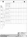
Analog K-Factor Settings Table
Manufacturer
Beech
Beech
Beech
Beech
Beech
Beech
Beech
Beech
Beech
Beech
Beech
Cessna
Cessna
Cessna
Cessna
Cessna
Piper
Piper
Lear
Lear
Lear
Boeing
British Aero
British Aero
British Aero
Canadian
Canadian
Dornier
Daussault
Daussault
Daussault
Swearngen
Gulfstream
Gulfstream
Aerospatiale
DHC
IAI
IAI
Sikorsky
Sikorsky
Sabre
DigiData Analog Fuel Flow Chart
Model
KingAir B200
KingAir A100
KingAir C90
KingAir F90
KingAir C90A
KingAir 200
BeechJet
KingAir B100
Beech 600
Beech 750
Beech 800
Citation, Ametek Gauge, 02C208E
Citation, Simmons Gauge, 393002-009
Citation II/SII
Citation III
Model 525
Cheyenne III
Cheyenne IV
Learjet
Model 36 (5V)
Model 36 (10V)
Boeing-737-300
BAE ATP
BAE-125-800
HS-125
CL600
CL601
DO-228
FALCON 10
FALCON 20
TFE-371
MERLIN
GULFSTREAM II
GULFSTREAM
III
PUMA
DHC DASH 8
ASTRA 1125
WESTWIND 1124
S-76A
S-76B
SABRE 65
Table 1
K-Factor
77000
26150
26150
77000
77000
77000
11530
26150
38460
30770
28840
16270
14300
16260
9610
21970
41950
46150
15380
11530
23070
1790
15380
8240
10480
6590
5120
46150
11530
7690
7690
38460
2880
2300
Offset
445
938
938
445
445
445
0
938
0
0
0
0
0
0
1172
0
0
0
0
0
0
405
0
0
0
0
0
0
0
0
0
0
0
0
76920
19230
9230
10480
46150
28840
9230
0
0
2344
0
0
0
2344
IM2803
IM2803MG.DOC., DIR. 912802
Shadin Avionics
INSTALLATION MANUAL
DIGIDATA
Rev: M
P/N 912802-A, 912802-03A, 912802-03A-G
Page: 9-4
SSEC and PSEC Selections Table
The following SSEC and PSEC corrections and available for the following aircraft with the listed
DigiData software versions. If your aircraft model is not listed in Table 2, select “no correction”.
CORRECTION For SSEC/PSEC Select:
- No correction
- MITSUBISHI MU-300
- CESSNA CITATION 500/501
- CESSNA 525
- CESSNA 550
- Citation 560 SN <=259
- Citation 560 SN >=260
- Citation 650
- Sabreliner 65
- WestWind 1124A
- Lear 24
- HS 125-3A
- Falcon 20-F
- Falcon 20-C, D, E
- Lear 25D
- Douglas DC-8
- Beechjet 400
- Boeing 707-321B
- Cessna Citation S550
- Falcon 10
- Falcon 50
- Hawker HS125-700A
- Learjet 35
- Learjet 55
- Sabreliner 60
- Lockheed Jetstar II
DigiData Display
None
MU-300
Cit. 501
Cess 525
Cess 550
Ces 560a
Ces 560b
Cit. 650
Sabre 65
WestWind
Lear 24
HS125-3A
Falc20-F
F20-CDE
Lear 25D
Doug DC8
Bchjt400
707321BA
Cit. S550
Falcon 10
Falcon 50
125-700A
Lear 35
Lear 55
Sabre 60
JetStar2
Table 2
DigiData Software Version:
ALL
93.10.29 - and up
93.10.29 - and up
93.10.29 - and up
93.10.29 - and up
93.10.29 - and up
93.10.29 - and up
93.10.29 - and up
93.10.29 - and up
93.10.29 - and up
93.10.29 - and up
93.10.29 - and up
93.10.29 - and up
93.10.29 - and up
93.10.29 - and up
93.10.58-and up
93.10.63-and up
93.10.63-and up
93.10.63-and up
93.10.63-and up
93.10.63-and up
93.10.63-and up
93.10.63-and up
93.10.63-and up
93.10.63-and up
93.10.63-and up
IM2803
IM2803MG.DOC., DIR. 912802
Shadin Avionics
INSTALLATION MANUAL
DIGIDATA
P/N 912802-A, 912802-03A, 912802-03A-G
Rev: M
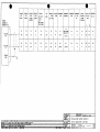
Navigational Receiver Types
Below find a listing of the DigiData input / output selection definitions.
Input Type:
4
4
4
4
4
4
4
4
Trimble (9600 baud)
ARNAV (9600 baud)
Bendix (IIMorrow Apollo NMS2001, 800, 820, GX50/55/60, 9600 baud)
Garmin (9600 baud)
Northstar
(1200 or 9600 baud, 1200 is the default for the Northstar)
Foster
(1200 baud)
IIMorrow 611, 612 and 618 (1200 baud)
FlowMeter DO NOT USE
Output Type:
4
4
4
4
4
4
4
4
4
4
Format Z - Trimble and Garmin
Format G - Garmin
Format X - ARNAV
Generic - DO NOT USE
Surveyor
Bendix D - DO NOT USE
Bendix C - Bendix/King fuel and airdata without Barometric Interface
Shadin S - IIMorrow GX50, 55, 60, CNX 80
Bendix B - Bendix/King fuel data
Format G - Garmin
Table 3
Page: 9-5
IM2803
IM2803MG.DOC., DIR. 912802
INSTALLATION MANUAL
DIGIDATA
P/N 912802-A, 912802-03A, 912802-03A-G
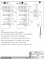
SECTION 10
INSTALLATION DRAWINGS AND
INSTALL KIT PARTS LISTS
Shadin Avionics
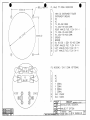
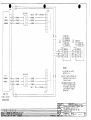
•
NOTES:
.&.
£
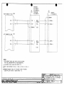
Pla3, TRANSDUCER PO\JER FOR LEFT AND RIGHT ENGINE.
FOR SINGLE ENGINE APPLICATION USE P111S LEFT FUEL
FLO\J DIGITAL SIGNAL IN ONLY.
l~
•
DRILL #18 (4)
Pi- MALE 'D' CONN. INDICATOR
1
2
3
4
5
6
7
.~?
\ 'j,S ;~~
eJ))'
•
8
9
10
11
12
13
14
15
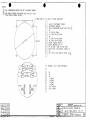
+28V DC INSTRUMENT PO\JER
INSTRUMENT GROUND
FLO\J TRANSDUCER PO\JER (+12V OUT)
NC
TX, RS-232 COMM.
TX, SDA+ RS-422 COMM,
NC
TX, SDB- RS-422 COMM,
RX, SDA+ RS-422 COMM,
SIGNAL GROUND, RIGHT FF
SIGNAL GROUND, LEFT FF
RX, RS-232 / SDB- RS-422 COMM,
RIGHT FUEL FLO\J DIGITAL SIGNAL IN
NC
LEFT FUEL FLO\J DIGITAL SIGNAL IN
&
£
<±)
P3, HEADING I
1
2
3
4
5
6
7
8
9
~07/021
D
7130/98
;05/020
C
5/15/96
N/A
B
9/9/94
N/A
I A
O,A,T. CONN, (OPTIONAL)
NC
NC
NC
Y SIGNAL
X SIGNAL
H SIGNAL
C SIGNAL
O,A, T.
PO\JER
O.A,T,
SIGNAL
""'9iio/9r'
APPROVED
RR
F'ILE NAME:
912802EJ.D'WG
8/30/94
DIR~.~TJ!~Y
SHAPIN
MINNEAPOLIS, HN
55426
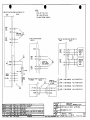
INST ALLA TIDN, DIGIDATA,
HI/LD FREQ INPUT TTL FF
DRA 'WING NO.
4005-479
Sr:,E
PIN 912802
IREV
D"
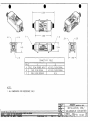
•
I
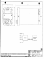
3.300
•I
•
I·
3,300
••
7,600
I
I
~
¢3.l4
HEADIN·G
1/
-STATIC
OAT
--
NAVIGATIONAL
RECEIVER
DIGIDAT A
-- RS-232 /
--
422 -
iI\
r
FUEL FLOw
9904/038 I E I 5/6/99
I PAB I pg
IREMOVED 'LEFT'
REV. I PAGE
r. 'RIGHT' FROM FACEPLATE 'VIEIJ, ADDED LOGO, SIJITCH BOOTS, AND BEZEL SCREIJ
9807/021
D
7/30/98
PAB
KCL IREMOVE SPECS,. ADD DIMENSIONS
9605/020
C
5/15/96
\IMP
RR
ICORRECT lAS, P.ALT, ADD RATE OF TURN, 'AIRDATA' TO 'DIGIDATA'
NlA
B
9/9/94
DAP
RR
IREMOVED CDNNECTOR INF"DRHAlIDN
D 1.2
E 1'1
PAGE HISTORY
SHAPfH
MINNEAPOLIS. MN
55426
INSTALLATION) DIGIDATA)
HI/LD FREQ· INPUT TTL FF
DRAIJING NO.
4005-483
SIZE
P/ 'N' 912 802
A
.
REV
E
·'r-===
2,500±02
~
DRILL
fll~-+)
PL MALE uD" CONN,
1
2
3
4
5
6
7
8
9
10
11
12
13
14
15
2.500±.02
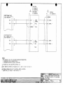
+28V DC INSTRUMENT PO\JER
INSTRUMENT GROUND
NC
NC
TX) RS-232 COMM,
TX) SDA+ RS-422 COMM.
RIGHT ANALOG FUEL FLD\J IN (-)
TX) SDB- RS-422 COMM.
RX) SDA+ RS-422' COMM,
GROUND
GROUND
RX) RS-232 I SDB- RS-422 COMM,
RIGHT ANALOG ,FUEL FLO\J IN (+)
"LEFT ANALOG FUEL FLO\J IN (-)
LEFT ANALOG FUEL FLO\J IN (+)
P3) HEADING I
1
4
5
6
®
®
®
®0
7
STATI
8
9
0®
O,A,T. CONN, (OPTIONAL)
NC
NC
NC
Y SIGNAL
X SIGNAL
H SIGNAL
C SIGNAL
O,A,T, PO\JER
O,A,T, SIGNAL
2
3
®
t
SHAPIN
"n,
APPROVED
_. - ..~rin
LIM
MINNEAPOLIS. MN
55426
IINST ALLA TION, DIGIDATA,
ANALOG FF OPTION
DRA'WING NO.
i
•
IN,DICATOR
~h,,? nD"Or.u:l~ur"~~5~USnr"~ I 4005-548
I A IPIN
SIZE
IC '
REV
912802-03
I
•
3.300
I
..
I·
3,300
•
7,600
,
@.
(l)3.14
HEADING
PIToT
STATIC
t
DIGIDATA
OAT
RS-232 / 422
NA VIGA TIONAL
RECEIVER
FUEL FLOW'
DRAVING-DATE
7/30/98
r---r-----.....,;,------------------------------1 APPRDVED
1----.---"""'T"---..r__
REMOVE 'LEFT'S. 'RIGHT' FROM FACEPLATE VIEW', ADDED LOGO, SW'ITCH BOOTS, AND BEZEL SCRE'"
7/30/'38 I PAD
KCL IBASELINE RELEASE
ALIe.
FIL~C~AHE
SHA.IJ./H
MINNEAPOLIS. MN
55426
INSTALLA TION DIGIDA TAl
ANALOG FF GREY FACE
I
I
1280203GAJ.DW'l4------"""'T"--r----------r'----1
REV
DIRECTORY
DRAIJING NO.
SIZE
EEl 1 DF 2
A
912802-03-G
4028-A23
I
P/ N
A
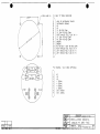
•
•
DRILL #18 (4)
l/2~
.ll?
N
~
\ 7,0J~~\
o
o
0::>'
10
N
U
EB
PI, MALE 'D' CONN, INDICATOR
1
2
3
4
5
6
7
8
9
10
11
12
13
14
15
+28V DC INSTRUMENT POW'ER
INSTRUMENT GROUND
NC
NC
TX, RS-232 COMM,
TX, SDA+ RS-422 COMM.
RIGHT ANALOG FUEL FLOW' IN (-)
TX, SDB RS-422 COMM,
RX, SDA+ RS-422 COMM,
GROUND
GROUND
RX, RS-232 / SDB RS-422 COMM,
RIGHT ANALOG FUEL FLOW' IN (+)
LEFT ANALOG FUEL FLOW' IN (-)
LEFT ANALOG FUEL FLOW' IN (+)
P3, HEADING /
1
2
3
4
5
6
®
®
®
®
®0
STATI
0®
7
8
9
O,A,T, CONN. (OPTIONAL)
NC
NC
NC
Y SIGNAL
X SIGNAL
H SIGNAL
C' SIGNAL
O,A,T, POW'ER
O,A,T, SIGNAL
DRAIJING DATE:
7/30/98
IDR1ATBER
APPROVED
KCL
9807/021
.,.
7/30/98
ECll •
REV,
DATE
•
~~~2~~J.DIJ
DI~f2";g~Y
:seA_E' NONE
SHEET
2 Of 2
SHA.lJIH MINNEAPOLIS, HN 55426
INST ALLATIDN, DIGIDATA,
ANALOG FF, GREY FACE
DRAIJING NC.
4028-A24
I IP / N
SIZE
A
912802-03-G
IREV
•
o
•
,0
'
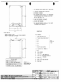
1.
•
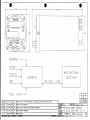
THE CONVERTER CAN BE MOUNTED IN ANY ORIENTATION
2, 4' SPACING IS REQUIRED ABOVE CONNECTOR
3. NO COOLING IS REQUIRED
2,94
(3.18)
4. THE CONVERTER CAN BE INSTALLED IN A PRESSURIZED
OR NON-PRESSURIZED AREA, PROVIDING TEMPERATURE
DOES NOT DROP BELO'vl -20°C
5. 1 AMP CIRCUIT BREAKER IS REQUIRED
6. NO SHOCK MOUNT REQUIRED
7, USE HARD'vIARE PROVIDED IN .INSTALL KIT PIN IK9337
TO ASSEMBLE MArING CONNECTOR.
CONNECTOR KEY
MATING CONNECTOR:
SHADIN PIN 230036, 17-DA15S
SHADIN PIN 230038, HOOD: #: DA-246
PIN
15 PIN MALE CONNECTOR
RS232 DR RS422 SELECT
1
1
(3.05)
<3.24)
2
TVIN OR SINGLE ENGINE SELECT
3
N,C,
4
N:C.
5
N,C.
N,C,
8
+14 TO 28 V DC
N.C,
SELECT PoVER (OUTPUn
10
RX+~
13
RS422
RS422 RXRS232 RX
14
RS232 TX, TO ARGUS 5000/7000
15
PoVER GND
12
RS422 RX
DEF AUL T <NO JUMPER REQ'D)
SINGLE ENGINE I Jl:7 TO Jl:2
I
T\v'IN ENGINE
I
'vIEIGHT: 8 oz.
PO'vlER CONSUMPTIONI
210 MO.. @ 28v DC
DIMENSIONS ARE IN INCHES
TOLERANCES:
9801/025
9707/023
EOO •
B
A
-
I REV.
", H-o.r
."
10112198
PAS
DMD
71 5/97
PAS
PC
RV
lAPP'£:
IlATE
PG
FROM SHADIN ADC
(USE RS-232 OR RS-422,
NOT BOTH)
DEFAUL T (NO JUMPER REQ'D)
UNL£SS OlHER'MSE NOTED
0501/032
PoVER' IN
SIGNAL GROUND
11
RS232 RX : TIE Jl:7 ~o Jl:l
SEE
SELECTOR
TABLE
6
7
9
SELECTOR TABLE
FUNCTION
UPDATED 11M BLOCK; CONVERTER WAS TXMTR
ADDED NOlE 7. CORREClID HEIGHT. PROV1DED SHAOIN PIN FOR t.lA11NG CONN.
BASEUNE RELEASE
SH:
x.x
:to.l
x.xx • :to.Ol
go
N/A
MATERIAL;
N/A
SCA1..£:
NONF'
DR~'~/f_A
7 14 97 TE
IU~1~?
APPROVED
PG
FIt£: NAME
37000-03BJ.DWG
DIRECTORY
937000-03
I~I
lot'
SHAPIN
t.lINNEAPOUS. loAN
55426
INSTALLATION, SERIAL TO
ARGUS 5000/7000 CONVERTER
4070 N°b05Is~ Ip IN 937000
031l3'
•
I.
•
5.228
•
-I
~
Th
J1: C
J1: A
J1: 8
CONNECTIVITY TABLE
PIN
A
B
C
J1
FUEL FLOW POWER INPUT
FUEL FLOW SIGNAL
FUEL FLOW ,GROUND
J2
AC FUEL FLO,W SIGNAL
AC FUEL FLOW SIGNAL
N/A
NOTES:
1. ALL DIMENSIONS FOR REFERENCE ONLY.
SHAD/IV
NINNE~OUS. I.lN
55426
INSTALLATION, SINE/
SQUAREWAVE CONVERTER
ADDED OlNENSlONS at ISONElRIC VIEW: REORAYtt4.
BASEUNE RElEASE
DRAWING NO.
4005-642.
f¥l p / N
A
631201
fEY
A
•
•
•
NOTES:
1.
REFERENCE PIN 681201-1 OAT PROBE
ASSEMBL Y KIT
2, AVOID INSTALLING OAT PROBE
IN OR NEAR:
PROP AIRSTREAM
ENGINE EXHAUST FLUW PATH
·CABIN HEATERS EXHAUST FLOW PATH
TRANSMITTING ANTENNAS (DME, TXP, COMM,)
DARK PAINTED AREAS
.&
OAT PROBE, PIN 681201
&
TORQUE NUT, FN 25, TO 1.3 IN-LBS (MAX)
@&
10 )4X
DRILL 0:098¢
AIRCRAFT FUSELAGE
(#40) 4 PL
DRILL 0.359¢
o
30
(23/64")
DETAIL A
MOUNTING HOLE DETAIL
~~;f~;IO~1H~~~I~~ ~~~fs Ut<~~~NJ91UAIt.
TOLE:RANCES'
10501/032 1 C 1 2,W·rJS'1 PAB 1"'-.,0 IUPDATED TIRE BLOCK a. NOTE ., ADDED 'KIT' TO TITLE
10lll/00t l s i 11/14/01 1 PAS r KCL -rSTANDARDIZED D'JG FORHAT TO MIHIC D'JG NO. 4012-177
IOOOU036 I A 1 3/11/96.1 WHP 1 Pu -rCONVERT TO CADI ADD NOTES 1 AND 3
It"·
_
- .• m m.
_ ......
_
~.. ~ -BASELINE RELEASE
SCRIPTION
rINISH.
:1:
0.01
N/A
MATERIAL·
N/A
~A~ 1'lQN~
F7
SHA.f)IN
HINNEAPl1.IS. MN
I
55.26
INS TAL LATID N)
DRAn pER
APPROVED
SES
FILE NAME
681201-1CJ.DW·
DIRf~;~~~:!:1
DRA'JINu. NO.
JSIZE
·
0 AT PRO BE ASS EMBL Y KIT
SHE:E:T
1 Or 1
4028-005
A
Ip / N68 20 _
I
1 1 1
(REV
C
•
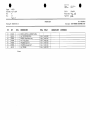
Report:
ECO Date:
Rev:
Sec.:
•
40320
April 4, 2007
H
IX
Page 1 of 1
Shadin Avionics
/0
511201
543216
670503
670504
670505
670506
681201
/5
20
25
30
35
40
681201-1
1-- IJ-
~
QTY.
4
I
I
1
1
1
1
DESCRIPTION
RIVET, AN4703-4 or MS20470AD3-4
OAT STIFFENER RING
SHIELD, Temp Sensor Assy
NUT, Temp Sensor
WASHER, Flat OAT
W ASHER, Shoulder OAT
OAT PROBE
10 items
MFG.
SHA
SHA
SHA
SHA
SHA
SHA
MFG.#
4032-082
4005-265
4005-266
4005-303
4005-304
4005-794
-::r
•
Pal1 #: 681201-1
Description: OAT PROBE ASSEMBLY KIT
PARTS LIST
PIN
68120 I-I IiP.doc
0704/002
ECO#:
Release date:
0
Approved:
Drawing #s: 4028-005 Rev C
FN
Filename:
DIRECTORY:
DESIGNATION
COM MENTS
•
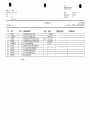
Report:
ECO Date:
Rev:
Sec.:
•
4028A
June 5, 1997
IX
Page 1 of I
Shadin
FILE NAME: IK9128-P.DOC
DIRECTORY: IKXXXX
ECO#
Release date:
Approved:
5
10
15
20
25
30
35
40
45
50
PIN
230018
230020-4
230036
230038
230019H-I
511002
512007
541001
PKI002
PKI005
QTY.
1
1
1
I
4
4
4
4
1
1
DESCRIPTION
CONNECTOR, 9 Pin D-Sub
HOOD 9 Pin D SUB Cinch
CONNECTOR, 15 Pin D SUB Socket
CONNECTOR, Hood 15 Pin D SUB
LATCH Clip Modified
SCREW, 4-40XI/4" Phil Pan HD SS
NUT, 4-40 3/16XlI16X.062 SS
WASHER. #4 Split Lock SS
BAG, 3X4X4 Mil Zip Lock
BAG, 4X6X4 Mil
22 items
MFG.
MFG.#
APH
I17-DE-9S
DE-24657
17D-A15S
DA-24658
17-529
••
OY23~8
PG
Pan ft.: lK9128
Description: INSTALL KIT, DIGlDATA
PARTS LIST
Drawing #s: nla
FN
97061013
DESIGNATION
COMMENTS
•
•
'
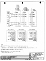
GARMIN
430
GARMIN
530
P4001
P5001
912802
912802-03
912802-03-G
BENDIX!
KING
BENDIX!
KING
KLN90
KLN90B
KLN89
GARMIN
LNS
150. 155.
155XL.
165.
250. 250XL
300. 300XL
6000
BENDIX!
KING
FOSTER IIMORRO'w'
360
7000
IIMORRO'w'
NMS2001
IIMORROV
820
KLN 900
IIMORROV
GX 50.
60
ARNAV
FMS7000.
R5000
STAR5000
•
MAGELLAN IIMDRRDV
SKYNAV
GX 55
5000
A
B
P1
RS-232
RX
'"
TX
\
I
12
\
\
,I
I
I
I
I
\
\
\
5
56
I
I
,
RX
I
I
I
57
I
RS-232
TX
TX
TX
TX
TX
TX
TX
TX
TX
13
2
24
25
6
A
8/1
RX
RX
RX
RX
RX
RX
RX
36
1
17
26
38
R
20/14
,,-..
-.
56
RX
57
TX
<SOFT'w'ARE
SELECT>
19/37
RX
21/38
TX
TX
TX
TX
TX
TX
6
5
3
12
25
6
RX
RX
RX
RX
RX
RX
7
4
4
11
23
7
\
I
I
SIGNAL
GND
2
-
1
"
--L
V
"
DRA7~~~~9~ATE
I
DR~I,lnEJ~
APPROVED
0211/004
0009/004
9807/021
E:
•
B
A
-
IRFV,
3/3/03
9/12/00
7/30/98
. DATE:
PAB
PAB
IlHD
BY
BAL PIN 2 \lAS PIN 10, ADDED' GND TO PIN 2
KCL ADDED GARHIN 430 .. 530 COLUMNS
I<CL BASELINE RELEASE
DE:S:CR P 'lllN
APP'D
rn
SCALE
:Ii~t-
I
MINNEAPOLIS, HN
55426
INSTALLAnON \JIRING. DIGIDAT A
KCL
f"lLE NAME
4028-AI9BJ.D\lG
DIRECTORY
4028
NOT
SHAPIN
[]f'
TO NAV REC~IVERS \J/RS-232
DRAWING NO.
4028-A19
I Ip / N
SIZE
A
IRf:r
•
•
912802
912802-03
912802-03-G
•
PI
1\
/
,-,
RS232 RX 12
RS422 RX+ 9
RS422 RX 12
RS232 TX
\
'
I
,'f
NAVIGATIONAL
&
¥
:
RECEIVER
¥
&
&.
,,-,
RS422 TX+ IS
I
RS422 RX+
\
I
I
I
RS422 'rX
RS232 RX
1\
5
8
RS422 RX
~
'-
J1
,
I
I
.p IN 937000-03
12
RS422 RX
11
RS422 RX+
I
~
\ j
.r..
13
14
'='
RS232 TX
"-
&
EVENTIDE
ARGUS
,PIN 5000
16 PIN 7000
'-I
,-,
¥
r
NOTES:
/
I
r
\
&&
\
I
\
V
/
SHADIN CONVERTER
r
4
RS232 INPUT HI
RS232 INPUT LOW'
"
JR RS422 NOT BOTH.
~
&
CONNECT SHADIN CONVERTER PIN 937000-03 IN PARALLEL WITH
NAVIGATIONAL ,RECEIVERS SERIAL DATA INPUT.
CONSULT DRAWING NUMBER' 4070-005 FOR WIRING AND
STRAPPING INFORMATION,
SHAPIN
i i i
9[2:°21
IRN I 711;18 I Di:
••
i
i
~L
~p
KCL
'w'IRING, DIGIDATA AND
SHADIN CONVERTER TO EVENTIDE ARGUS,
DRAIJING NO.
I BASEUNE RELEASE
55426
IINSTALLATION
IAP~~nOMVED
I
MINNEAPOLIS. loiN
4028-A20
I
SIZE
A
I
P/ N
REV
•
I
•
.~.
912802
912802-03
912802-03-G
TRIMBLE
TRIMBLE
NORTSTAR
1000,
2100,
MIA
2000,
2101.
3000
3100
RX, SDA+
RX, SDA+
•
'.
'.
M2
M3
60/600
P1
1""\
/-,
I
RS-422
TX, SDA+
\
\
I
I
6
\
I
\I
I
I
I
I
I
I
I
I
I
I
I
I
I
I
I
I
I
I
,
,
8
I
I
I
)
I
\
I
I
9
RX, SDB
4
8
IX, SDA+
IX, SDA+.
IX, SDA+
15
37
11
TX, SDB
TX, SDB
TX, SDB
3
5
6
. \\
I
I
I
I
I
I
I
I
I
I
I
I
I
I
RS-422
RX, SDB
RX, SDB
N/A
I
.I
\\
\
RS-422
RX, SDA+
7
I
I
RS-422
TX, SDB
N/A
16
I
I
I
I
I
I
,
I
I
I
I
I
12
I
I
\
\
I
\
~I
I
I
I
_
GND
2
• .1'
/
.........- -L
-
L.../
DRA7~~~~9~ATE
IDRArillJ-R
APPROVED
0211/004
9807/021
F"CIJ
•
A
-
I REV.
7/30/98
PAD
JlMD
DArE
R'
3/3/03
SAL
KCL
IAPP'D
DIRECTORY
icn;:CALE
ISHEE:
:5:5426
TO NAV RECEIVERS 'w'/RS-422, RS-485
DRA'WING NO.
4029
NDT
MINNEAPOLIS. MN
INSTALLAnON 'w'IRING, DIGIDA TA
KCL
IrJ~ij-~r;J.D'WG
PIN 2 ""AS PIN 10J ADDED GND TO PIN 2
BASELINE RELEASE
SHAPIN
I:Ir I
4028 A21
I Ip/ N
SIZE
A
IA
•
+~
/1
-+
~
ill
-
fUEL FLOW
TRAHSlolITTER
~
H
.&
SIGNAL
CONDI1lONER
+~
-
A
I
/1
-
-
fUEL flOW
INDICATOR
+9
ffi
FUEl.. FLOW
TRAHSlolITTER
+~
&
H
I
/1
+
.
•
LEFT
ENGINE
SIGNAL
CONDl11ONER
/"1
~~
&
A
&
FUEL FLOW
INDICATOR
&
RIGHT
ENGINE
SIGNAL
CONDI11ONER
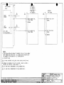
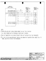
NOTES:
ill
ffi
DICITAL/FREQUEHCY
912802
&
P1
GROUND
RIGHT
FUEl..
FLOW
LEFT
FUEL
FLOW
2
SlG
GND
10
+12Vdc
"-
\ I
v
15
GND
11
,
,
I \
I \
II
I ,
W
\
I
R ENGINE
\.
.
SINE TO
SQUARE WAVE
1\
CONVERTER: :
SHADIN PIN
631201
\:
&
+
-
•
L. ENGINE
SINE· TO
SQUARE WAVE
1\
+
CONVERTER: I
.
I I
SHADIN PIN
t-~\-t',------
n
S1G
ill
/'---------:..-----------',,-
,,/
3 I-M-t-----.;..n1---I
/ I
13
~W
'-"......
!
&
&
ill
AEROSPATIALE AS332 SUPER PUMA WITH FAURE-HERMAN
FUEL FLOW TRANSMITTERS piN TN(A)-512-231-1. K-FACTOR=1.940 PPG.
AEROSPATIALE AS365N2 DAUPHIN WITH FAURE-HERMAN FUEL
FLOW TRANSMITTERS PIN TN(A)S-1024-118. K-FACTOR=3.880 PPG.
FAIRCHILD SA226 WITH FUEL FLOW INDICATOR PIN DSF1549-2, -4. -5.
K-FACTOR=26,800 PPG.
ROCKWELL COMMANDER 690 AND 695 WITH INDICATOR PIN(S) 850590-1.
-507, DSF1549 OR 05154-9. TRANSMITTER PIN(S) 850590-513. -515,
TFF2905-11 OR 151-906-001. K-FACTOR=27,600 PPG.
MITSUBISHI MU-300 AND MODEL 400 BEECH JET WITH SIGNAL CONDITIONER
PIN 45AS86801-003. K-FACTOR 5,150 PPG.
MITSUBISHI MU-2 WITH FOXBORO PC-620 FUEL FLOW SYSTEM PIN
PC-620-0098 SIGNAL CONDITIONER. K-FACTOR=33,800 PPG.
SHIELDING SHOULD' BE CONTINUOUS. TERMINATE AT DIGIDATA.
,/
- _----------------~"
.... ....
DRAWNG DATE
7/30/98 .
[n'R"AFlffi
"PAR
APPROVEO KCL
SHA.lJ././V
~71021
ECO- ,
A
3/11/03
-
7/30/98
REV.
DATE
PAS
DMD
JlY
BAL
402&-A22AJ.OWG
DIRECTORY
ADDED'NOTE 7 &: P1:2
Ket.. BASEUNE RElE~
~
~-'X
•
~
:..I:rnHt.
4028
~
..l.2E.l
55426
INSTALLAllON WIRING, DIGIDATA, SINE
TO DIGITAL FF CONV, VARIOUS AIRCRAFT
n~N~E
)211/004
MINNEAPOLIS. t.lN
DRAWNG NO.
4028- A22
lSiZE
A
Ip/N
1A
. I
REV
I
•
~.:----------.
.~
HIliH LEVEl.. FUEL FLOW' OPTION CHI/LO FREQ INPUT TTL>
USE LEFT FUEL FLOW'
ONLY W'HEN INSTALLING
ON SINGLE ENGINE AIRCRAFT
1.
<DIGITAU
912802
I
I
....
P1
RIGHT
FUEL
FLO'W
LEFT
D.C. FUEL FLO'W OPTION (ANALOG)
912802 -03
FUEl..
FLO'W
FREQ. FUEL FLOW' OPTION <HI/LO FREQ INPUT TTL>
912802
<DIGITAL>
P1
GROUND
~
P3
I-
I,
DAT [ 5::1 :
RIGHT
FUEL
FLO'W
26V 400Hz
Y
+SIG
.$IG 15.
9602/050
9502/007
9409/004
n/o.
n/o.
Eca _
SIG
13
GND
10
TRANSDUCER
SHADIN PIN
680501-X
DR
6605XX
LEFT
FUEL
FLOW'
2
GND.
SO
j
TRANSDUCER
SHADIN PIN
680501-X
DR
6605XX
1'5R
11
14
TEMP
PRaBE
z.Hcl:~
7/30/98
B
7-12-94
A
6-23-94
PAD
WMP
'w'MP
SES
WMP
DAP
DAP
REV.
DATE
BY
E
·D
C
/I
.,2T
X I 5 1-1-+1-+1--
FREQ. FUEL FLO'W aPTION (HI/LO F"REQ INPUT TTL>
~/N
9'2802
PI
3/26/96
3-11-96
2-9~95
9 8-94
KCL
SES
SES
SES
. SES
sES
SES
. APP'D
J:DIGlT~
HAGNESEN F.F.
Te FREQ. CONVERTER
J1
PIN 930503
P1
L.
FF. SIGNAL
R. F.F. SIGNAl..
GROUND
G
F"
13
-siG 1141
RIGHT
FUEL
FLOW'
>
-SIG 17
,--t-f--
~
9807/021'
%03/066
111
5TDmYDC
F"DR
FULL SCALE
(HODEL DEPENDANT>
LEFT
FUEL
FLO'W
COtoPASS
HEADING
P1
1'5 ~
~1l IL.
13
FREQ. F.F. OUT
12 R. FREQ. F F. OUT
11
13
~RIP~
1 COND SHIELDED
-MIL-C-27500-22TGITI4
£.-'w'IRE'
2 CqND SHIELDED
-MIL-C-27500-22TG2TI4
.&.-'w'IRE'
3 CDND SHIELDED
-MIL-C-27500-22TG3TI4
ill-IJIREI
4 CDND SHIELDED
-MIL-C-27500-22TG4TI4
GROUND
DRA'WING DATC
7-14-92
. REMOVE PAGE 2, P113· VAS 15V
REMOVE LIST OF" MATERIALS
ADD GND'5 ON PI
CORRECT PIN's
LABEL CONtIGURATIDNS & WIRE spECS. +12V BECOMF'S +~
ADDED ' . ' NOTE.
MOVED XDCR PO'w'ER TO PIN 3
£-'w'IREI
UI<~J. I ~~~LLA'"
APPROVED
SES
I~:2~2~GJJ),r
.
...m-tiWZftLE~
PIR~~~RY
SHEff 1 1lF"1
SHAPIN
MINNEAPOLIS HN
55426
INST ALLATIDN 'WIRING)
DIGIDATA FF
DRAWING NO.
4028-207
IA
SIZE
~
-
IN
IRGV.
i
•
•
•
NOTES:
.& \-lIRE:
£ \-lIRE:
SH~ELDED
2 CDND ,
MIL -C-27500-22TG2T14
3 CDND , SHIELDED MIL -C-27500-22TG3T14
~SHIELD
SHOULD BE CONTINUOUS GROUNDED BACK TO
DIGIDATA.
DIGITAL/FREQUENCY
912802
PI
~-_
GROUND
RIGHT
~~~
LEFT
~~5~
{
-~
_
SINE
IJAVE
FUEL
FLOIJ
PICKUPS
..
2 t--e::Jo:-----,
+12V
3
SIG
'GND
13
10
SINE TO
SQUARE 'WAVE
CONVERTER
SHADIN PIN
631201
R. ENGINE
SINE TO
SQUARE IJAVE
<
SIG 115
GND 11
CONVERTER
'SHADIN PIN
631201
................................. __
..
IDRA'JING ,DATE
9-9-94
0211/004
9807/021
9602/050
19502/007
19409/012
19409/004
Ern It
E
D
C
B
A
-
REV.
3/11/03
7/30/98
3/11/96
2-9-95
9-21-94
'9-9-94
DATE
PAB
PAB
IJHP
DAP
DAP
DAP
BY
BAL
KCL
SES
SES
SES
SES
APP'D
' ADDED PIN 2 &. NOTE 3) MODIFIED SHIELD GROUND CDNFIGJ 'EDllED NOTES 1 &. 2
SEPARATE FROM 4028-207 DRAIJING
ADD GND ON PI
CORRECT PINS
LABEL CONFIGURATION 12VDC TO 15VDC
:
RELEASE
DESCRIPTION
SHAPIN
MINNEAPOLIS HN
55426
i1JI<A~~~I'IAN
INST ALLA lION YJIRING)
APPROVED
SES
DIG IDA TA) FF
ILE NAME
4028-373EJ.DIJG
DRAIJING NO.
IR~~~2RY
ISIZE II
A PIN
4028-373
DO NOT SCALE DRAIJING SHEET l
OF l
I REV.
•
•
•
NOTES:
1 CONSULT OPERATIONS MANUAL FOR
DIGIDATA PROGRAMMING INSTRUCTIONS.
PI
+28VDC I 1
GND
2
TX
J
RS232 I 5
RX
J
RS232 I 12
---L
:.:~~
[DRAlJING DATr-1
2/23/96
_--,----,-_--r_,-......
crUA nrw
JJ~.t1.u1J
HINN£APOLIS, HN
55426
::RDr::D "HP
INST ALLA TION \JIRING
~------___1~"":'T':":':;=SES::....t
LOOP BACK HARNESS
DRA'JING NO.
SIZE P/ N
4028-716
A
J
REV
------
.
------=,....--------------------------_.
. -------------------------
o-sue:
~12802~'·.·
12l102-03-C
;«
~"D
r-.
(;ROUND
/1
12 t-e::::k
....L
-SIC
+SlG
;===1~
I'cd
13
&
'
PART NUW8ER
. NUW8ER
101-384153-1
PC900-XAXXXXPH
~,-e). (A,.). (1,2).
OR
llC)- 38()()()8-~
\
I
DC
RIGHT
FUEl
FlOW
/1
PART NUWIIER
llC)-38()()()8- 2
OR
101-384153-3
;==1~
'-.
-9J
+
&
CUR't€D
PC9OO-XAXXXXPH
~P_~.~
(1 -8). (A,.). o.
PC9OO-XAXXXXPH
~PAAT~~
(A,.), (1.2)~7.8),
FAa:)
(CUR~,Jn.AT"FACE)
FlAT FAa:)
+
K
L
K
&&
+
&&
\
I
-SiG
+SlG
1::1
.
(i
\
J
~
\
r1
90-380009-2
OR
90-380009-~
-9J
+
,I
PART HOWSER
c
-~
+
&
~ . PC9QO-XAXXXXPH
PAAT~_
P-6).
(A,·). (1,2).
PART NUWBER
101-384153-1
OR
CUR~
101-384153-3
-
+
J
(CUR~,Jn.AT
FlAT FAa:)
-
P
K
+
L
-
K
+
-~
FACE)
l
K
&&
&&
&
PAAT~.~
(1-8). (.....). O.
1PAAm~
•
&&
PC9OO-XAXXX)(PH
PC9OO-XAXXXXPH
~7,8), (.....). (1,2).
FAa:)
I
1
'J
~
DC
lfFT
FUEl.
flOW
L
K
+
&&
E
RAGEN PART
NUWBERS
IHOlCATOR
J265013-0601
.&
lRAHSWITIDf
3268011-01 01
NOTES:
.& THIS
SCHEMATIC IS USED FOR KNOWN
BEECH KING AIR MODELS. SOME INDICATORS ARE NOT LISTED BUT MAY BE INTERFACED.
CALL SHADIN TECH SUPPORT IF YOU DO NOT SEE THE PART NUMBER OF YOUR INDICATOR LISTED. INDICATOR PART NUMBERS
POSSESSING A PREFIX OF "PC900-" ARE XOTECHNOLOGIES TYPE INDICATORS. THE LAST DIGIT REPRESENTS THE INDICATOR
AUXILIARY RATE OUTPUT (1 NUMBER). SHADIN SUPPORTS THE "-1" MODELS ONLY.
.& XOTECHNOLOGIES INDICATOR
P /N PC900-XAXXXXPH-XXO IS NOT SUPPORTED. THE AUXILIARY RATE OUTPUT OF THIS UNIT IS 0-1
rnA. INDICATOR P/NS THAT END WITH .A "-XX2" WILL ENCOUNTER A DEGRADATION IN PERFORMANCE DUE TO THE AUX. RATE
OUTPUT OF 0-5.333 VDC. INDICATOR P/NS ENDING WITH AN "." ARE UNKNOWN.
&
&
&
THE FOLLOWING XOTECHNOLOGIES INDICATOR P/NS POSSESS A K-F ACTOR KNOWN TO SHADIN:
ADC200/2000 SWITCH SETTINGS
SW1
SW2
SW3
SW4
PART NUMBER
K-FACTOR/OFFSET
AUX RATE OUTPUT
PC900-1 A0600-XX1
PC900-1A0750-XX1
38,460/0
30,770/0
0-5 VDC
0-5 VDC
0
0
4
5
0
0
PC900-1 A0800-XX1
28,850/0
0-5 VDC
0
6
0
o
o
o
THE FOLLOWING BEECH INDICATOR PINS POSSESS A K-FACTOR KNOWN TO SHADIN:
P ART NUMBER.
~CTOR 10FFSET
90-380009-2
90-380009-5
10l-384153-1
101-384153-3
77,000/416
77,000/416
30,777/0
30,777/0
ADC200!2000 SWITCH SETTINGS
SW1
SW2
SW3
SW4
000
000
050
050
1
1
0
0
L~FT
PROGRAM DIGIDATA FOR
/RIGHT K-FACTOR TO 46160 PPG, LEFT/RIGHT OFFSET TO O. THIS CONFIGURATION. IS TYPICAL FOR
PIPER CHEYENNE MODEL PA 31T.
6. USE SHIELDED WIRE, BUT GROUND ONLY ON ADC UNIT END TO PREVENT A GROUND LOOP.
IOR~'~~9~A 1£
,Url:Ar" /;)MAn
PAe
"
"'~~'JEO
BASEUNE RELEASE
SHAD/IV
UINNEAPOUS. loAN
55426
INST WIRING, OIGIOATA WITH ANALOG
FUEL FLOW INDICA TORS
DRAWING NO.
4028-820
SIZE
A
P IN
REV
B
~.~
-.
I
P13
P76
J5G P5G
f------.,.
SIGNAL
V
'vi
~ EO.8A20
E06A20
GROUND
U
E05A20
R/H
•
=ill'vl=
GND 8
i11P--
T
E08B20
E06B20
-------lE
S
E05B20 - - - - - - - l C
E04A20N
G
r-
B
I--
K
J
I
L
'-
l=l
L:I
Z
..
0::
0::
L:I
CI)
F IADC-200,
PIN 962810-3,
PIN 962820-3.
£
F IADC-2000,
&
DIGIDATA
PIN 912802-03
PIN 912802-03-G
P IN 962830-3,
P1
J1
.,.------, 3
-+-'1-------1 2
L----~r-------1 1
--r=r---I10
+----,1---1 9
GROUND
RIH SIG.
R/H SIG.
L/H SIG,
L/H SIG,
11
13
7
15
14
+
+
GROUND
R/H SIG.
R/H SIG,
L/H SIG..
L/H SIG.
+
+
NOTESI
L/H
GROUND
D
F
SIGNAL
~
.
E
~u
J49 P49
E15A20
T
E15B20
E16A20
U
E16B20
E18A20·
V
E18B20
'IIP--
GND 7
l=l
V;
I.:J
.J
.J
£. SET
z
a
E14A20N
~I
L
P77
~
FUEL FLD\J
OFFSET IS 0,
L:I
E
~II
IND. 15
1. K FACTOR IS 16,270,
F I AUC S\./ITCHES AS
FOLLO\./S S'W1=0, S\./2=C,
S'vI3=0, S\./4=0.
PROGRAM DIGIDA TA FOR
LEFT K-FACTOR= RIGHT
K:"'FACTOR= 16,270 PPG,
LEFT OFFSET= RIGHT
OFFSET=O.
INDICATOR
~INGDATEI
3/24/98 . I
IDR1RTBER
no-..
A
-
I ~v.
Z."·Il~
3/26/98
..MI.E.
.
PAB
SRB
..IY
. " , UPDATED TITLE BLOCK
KCL BASELINE RELEASE
~
..K..sgyP~
..I!L.K~
55426
r6ki~~~J.D'WG
. DRA'WING NO.
4028
Jill!
MINNEAPOLIS, loiN
DIRECTORY
APPROVED
KCL
0501/032
9803/025
SHAPIN
INSTALLATION VIRING, F I ADC200, 2000
OR DIGIDATA 'WITH DC FF TO
CESSNA CITATION 500, 50L 550,
S550, 551, 552.
~.!.~.!
4028- 936
lSlZElp /
A
N
~
IREV
A
/-.
PIO02
,7.
A
I
PC048
r------.
R/H
CFUEL FLO\J P.C.BJ
:t2
SIGNAL
GROUND
•
\.J
12
14
l-J--
I
+
8
8'
V?
V?
~
~
F IADC-:-200,
PIN 962810-3
PIN 9.62820-3.
£
&
F I ADC-2000,
PIN 962830-3.
P1
J1
3
-(-t-----1 2
L------'=':f-----1 1
---r=........----110
--t-+-----1 9
~--,
r-
I-
DIGIDATA
PIN 912802-03
PIN 912802-03-G
GROUND
R/H SIG.
RI H SIG.
L/H SIG.
L/H SIG.
11 GROUND
13 R/H SIG.
7 R/H SIG.
15 L/H SIG.
14 L/H SIG.
+
+
+
'-l
I
'--l
+
I
PIOOl
NOTES:
':rts
GROUND
SIGNAL
I ~~
1. K FACTOR IS 21,980
OFFSET IS O.
+
PC047
L/H
8
LJ
.....
V?
V?
.J
.J
&
CFUEL FLOW' P.C.BJ
&
~
v-r"\ n
(EIOOD
FUEL FLO\J
INDICATOR
'7
I
3/24/99
DRA~TJfR
APPROVED
.
KCL
A
-
--reDI
I
REV.
~·''¥.,S PAB
3/26/98
JlAK
PROGRAM DIGIDATA FOR
LEFT K-FACTOR= RIGHT
K-FACTOR= 21,980,
LEFT OFFSET= RIGHT
OFFSET=O.
~
DRA'l1TNUDATE
0501/032
9803/025
SET FIADC S\JITCHES AS
FDLLO\JSj S\Jl=O, S\J2=E.
S\J3=0, S\J4=O.
SRB
. " UPDATED TITLE BLOCK
KCL BASELINE RELEASE
~~
~fUP.I.lON
rJM-~;~.D~G
DIRECTORY
4028
'
..1!lll~CAL~
~
.!.!!!:....l
cr LTA n
TW
AJ.Ll.dU.L.i
MINNEAPOLIS. HN
55426
INSTALLATION W'IRING, F IADC200, 2000
DR iHGIDA TA 'WITH DC FF TO
CESSNA CITATION 525 JET
DRA'WING NO.
4028- 9 3 7
jSIZElp
A
j'N
jREV
.A
~07
' .
FUEL'l',wNITOR
<TAIl)
I·
! RIGHT
! ENGINE
!
I
SIG! 11 :
Z
!
i
i
AA
I
!
l:
! i
!
I
!
I
!
LEFT
ENGINE
SIG
·
!
i
I
i
!
!
'I
12!
I
I·: J.E.T. CARD
:!I !!.
I PIN 54·2....:1158.:...02 I
I
£
t-t-+-+---
F IADC-2000
PIN 962830-1
J1
. ill
DIGIDATA
P1
PIN 912802
I
i
I
&
r---r'
I
!
I
PIN 962810-1
PIN .962820-1
--r
I~-
•
F/ _ _ OO
I
i
2
RIGHT 'ENGINE FUEL
FLOV SIGNAL
3
GROUND
-----------8-1
-1 3 1. RIGHT FUEL FLO'W
SIGNAL
(\&
:lJl
o
I
l1D. LEFT ENGINE FUEL
FLO\J SIGNAL
1------
:
~
151 SIGNAL
LEFT FUEL
FLOW'
I"
.1l I GROUND·
.1---------'
~
1. THIS INSTALLATION APPLICABLE TO AIRCRAFT \JITH JET, FUEL MODULE
PART NUMBER .542-1158-02 ONLY. J.LT. MODULE NOS. 542-1158--01 MAY
BE CHANGED TO 542-1158-02 BY J.E.T. SB542-1158-7B.
2. K-FACTOR IS 860.
&
~
SET F IADC S\JITCHES AS FDLLO\JSJ S\Jl=D, S\l2=D, S\J3=D, S\J4=D.
=
&
PROGRAM THE DIGIDATA FOR LEFT K-FACTOR
RIGHT K-FACTOR
860 PPG, LEFT OFFSET = RIGHT OFFSET
Q
J.E.T. CARD PIN 11 CORRESPONDS TO FUEL MONITOR PIN Z.
&
J.E.T. CARD PIN 12 CORRESPONDS TO FUEL MONITOR PIN X.
=
In~~Jl8ATE1
DR~
APPROVED tea..
1F'Jl.E ~~
0:501/006
98031025
-rm.
-
V17/03.
3126/98
I REV.
DATE
A
. PAD
SRB
~
ZK
CORRECTED NOTES 1. 5. .. 6
KCL
BASEUNE RELEASE
~
~
rwa&-93SAJ.'DVG
DJRECltJRY
.
...!!Ll.lll~
4029
~
.!...Qf.1
·SHA.f}..IJV
MINNEAPOLlS. MN
55426
INSTALLAnON 'vIIRING, F I ADC200, 2000
OR DIGIDATA 'WITH DIGITAL FF to
l
4028- 938
BOMBARDIER LEARJET 24', 25D.
DRA'JING NO.
sIZE
A
I /N
Ip
1.
.
A
I
.
REV
•.
.,
.'
:
F IA'DC-200
PIN 962810-3
&
RIGHT ENGINE F IF IND. P080
PIN 962820-3
&
FIADC-2000
PIN 962830-3
Jl
~I
SIG. -Ip
111 GROUND
M
I .
SIG. +1 L~
LEFT ENGINE F IF IND.
SIG. -
ENGINE
I
II
~
DIGIDATA
PIN 912802-03
PI
J
2
SIG +
FUEL
3 GROUND
.1
J
--------------1.;. ----~ 131 R.
SIGNAL +
FLO'w'
P079
~I
I
W----P: I
P
SIG. + I L
1 J j 9 SIG I
10 .SIG +
~
>
LEFT
ENGINE
FUEL
t---------------~---~
14 I L
'
I I
I
I
---------..;-----tj-----! 15 I L.
SIGNAL
SIGNAL +
FU~W'
~
-
~
1. FOR AIRCRAFT SERIAL NOS. RK-45, RK-49 AND AFTER
\tilTH FUEL INDICATOR PART NO. PC900-3B2000-PHl.
2. K-F ACTOR IS 11.54 (11,540 PPG), OFFSET IS O.
&
SET F I ADC S\JITCHES TOt S\Jl :;; 0, S\J2 :;; 2, S\J3
= 0,
S'w' 4
= O.
~PRDGRAM DIGIDATA FOR .LEFT K~FACTbR :;; RIGHT K-FACTOR ~
11,540 PPG, LEFT OFFSET
= RIGHT
OFFSET:;; O.
IDAA\JING ·DATE
3/24/98
JJ~'At.K
APPROVED
.
ICCL
.
0501/032
A
98031025 . ECD.
'REV.
I·~·W-m
31261'8
VAJ.J;;
PAB
SRB
Jf1
~
UPDATED TITLE BLDCK
~
~ lAM
KQ.
ImE
.
BASELINE REUASE
.
...mn Jll.~
NAYl'
~'JG
_CIiJ((
«128
1.R!l:&l.J..J.!!: ...l
I
. C'LTA nTJIT .
JJJ-IJ1.1/~.LY
HINNEAPDUS. HN
554~
INSTALLATION 'WIRING, F IADC-:200, 2000.
OR DIGIDATA 'WITH DC FF TO RAYTHEON
BEECHJET 400A AIRCRAFT
DRA'JIHG
No.
40?B-940
. - - -
-
'
lSIZElp/N
A
.
I
IREVI.
lA
".
.,.
'-'
~
~
r.
~i
SIG.+IK~
,'-'"
SIG. -IL
I
I
.1
I SIG
~ 21 SIG
I
I I
-
}
+
3 GROUND
~I--
ill
F/ADC-2000
PIN 962830-3
Jl
RIGHT ENGINE FUEL
FLOV INDICATOR
'e·
- F I ADC-200
PIN 962810-3
PIN 962820-3
RIGHT
ENGINE
FUEL
DIGIDATA
PIN 912802-03
PI,
t--------------- / 1 1 1 IGROUND
---------------D-----I- I R. SIGNAL
~ 7
- --
SIGNA~
131 R.
+
FLO'v/
LEFT ENGINE FUEL
FLOV INDICATOR
~.
SIG.-IL~
SIG. +1
I
I
DI j 9, S I G - }
I
K~
,
,10
SIG
+
LEFT
ENGINE
FUEL
t-------------l---~ 14 I L. SIGNAL
-------------L----~
151 L. SIGNAL +
I:
I
FLOV
I,
L--- ---- ,-
~
1. FOR A'IRCRAFT VITH THE FOLLOVING INDICATOR/TRANSMITTERSJ
A. INDICATOR PART NO. <RAGEN) 1291-2
B. TRANSMITTER PART NO. (GULU 151-909-001
2. K-FACTOR IS 10.49 <10.490 PPG), OFFSET IS O.
&SET AIRDATA SVITCHES AS FOLLDVSJ SVI
=L
S'v/2
= 8,
SV3 = 0, SV4
~PROGRAM DIGIDATA FOR LEFT K-FACTOR = RIGHT k-FACTOR
= O.
=
10.490 PPG, LEFT OFFSET ::: RIGHT OFFSET ::: 0.'
DAAVIRUllATEI
3/25/98
DRAFTeR
UPDATED IDLE Bl:DCK'
BASElINE RELEASE
,. I
-
C'LTA
nrw
AJ.L~.a.L;/.L.I
MINNEAPl1..IS. MN
5Sf26
INSTALLATION 'WIRI~ F IADC-200i 2000
DR DIGIDA TA 'WITH DC FF TO 'vIEST\r/IND
1124 MODELS
DRAIJING tm,;
4028-941
SIZE
A
P/ N
REV
A
•
•
F/ADC-200
PIN 962810-3
PIN 962820-3
~
&
Jl
RIGHT
ENGINE
FF
INDICATOR
m
LEFT [ A
ENGINE
FF
INDICATOR
, FI ADC-2000
PIN 962830-3
PIN 962830-3-S-5
3 GROUND
~
...
I :
:!
i
1 SIG-}
RIGHT
ENGINE
2 SIG +
FUEL
FLO'w'
9
:
!
SIG - } LEFT
ENGINE
10 SIG +
mE
RAGEN PIN 3265013-0601
' FUEL
FLO'w'
•
:
£
Jl
I
FIADC-2POO
PIN 962830A-3
-----{-+---~
43 I R. SIGNAL
1,1
-----!::.~---~ 24 I R.
[----r----,26I
---- J---~
SIGNAL +
L. SIGNAL
,12 I L. SIGNAL +
J1
E
G·
J
B
F
C
A
D
H
K
Pt
n
( 1 2 3 I GROUND
11 I GROUND
-----r£---J 7 I R. SIGNAL
I .
-:-----ld----l 131 R.
SIGNAL +
1------F-l---'l'14 I L. SIGNAL
I------'-J----l
15 I L. SIGNAL +
RAqEN PIN 3265013-1201
Jl
FLO\ol SIGNAL FROM FLOVMETER
FLO\ol SIGNAL TO TOTALIZER
AL T FLO'w' SIGN~L TO TOTALlZER
+28 VDC INPUT
REF SUPPLY TO TOTALIZER
REF SUPPLY TO FLO\oIMETER
28 VDC RETURN,
SIGNAL RETURN FROM FLO'w'METER
SIGNAL RETURN TO TOTALIZER
CASE GROUND
DIGIDATA
PIN 912802-03
I
RAGEN PIN 3265013-0801
FLO'w' SIGNAL FROM FLO'w'METER
FLO'w' SIGNAL TO TOTALlZER
INTERNAL TEST PQINT
+28 VDC INPUT
REF SUPPLY TO TOTALIZER
REF SUPPLY TO FLO'w'METER
28 VDC RETURN
INTERNAL TEST POINT
SIGNAL RETURN TO TOTALIZER
CASE GROUND
&
PIN 962830A-3-S-4
PIN 962830A-3-S-5
'E
,G
J
B
F
'C
A
D
H
K
I
Jl
FLO'" SIGNAL FROM FLO'\V'METER' E
FLO\ol SIGNAL TO TOTALlZER G
ALT FLO'w' SIGNAL TO TOTALIZER J
+28 VDC INPUT B
REF SUPPL.Y TO TOTALIZER ' F'
REF SUPPLY TO, "FLO\olMETER C
28 VDC RETURN A
SIGNAL RETURN FROM FLO\olMETER D
. SIGNAL RETURN TO TOTALIZER 'H
CASE GROUND K
~,
ill FOR
AIRCRAFT \lITH THE FoLlo'WING INDICATOR/TRANSMITTERS; SEE TABLE FOR INDlcATOR 'WIRING.
INDICATOR PART NO. (RAGEN) 3265013-0601 w/TRANSMITTER PART NO. (RAGEN) 32'68011-0101.
INDICATOR PART NO. (RAGEN) 3265013-0801 + 3265013-1201 w/TRANSMITTER PART NO. (RAGE~) TFF-2905-9 OR PIPER PIN. 489-487.
~SET AIRDATA SVITCHES AS FOLLO\lS; S'Wl =
1, S'W2 = 1, S'W3 = 0, S'W4
m.PROGRAM DIGIDATA FOR LEFT K-FACTOR = RIGHT K..:'FACTOR = 46,160
PPG, LEFT OFFSET = RIGHT OFFSET = O.
= O.
•
••
SHADIN PIN
912802 OR 912802-G
.ill
+28VDC INSTRUMENT PO'WER
SHIELD/INSTRUMENT GROUND
FUEL FLO'W TRANSDUCER PO'WER
LEFT FUEL FLO'W SIGNAL
LEFT FUEL FLO'W GROUND
SHADIN F/F
~--
"'
1
2
3
15
11
L..c::k..
~
I~
I, )
-b
1\
I\
I I
'
~
v
I
680600D
LEFT
A
B
C
&
SHADIN F/F
&
•
&
1\
I\
,
I I
\
V
RED
'WHITE
BLACK
\
+
I
RIGHT FUEL FLO'W SIGNAL 13
RIGHT FUEL FLO'W GROUND 10
RIGHT
RIGHT
~
1\
i:
i:
I I
I ,
I I
\ I
v
v
1\
A
B
C
I\
\I
v
RED
'WHITE
BLACK
NOTES:
&
W'HEN INSTALLING UNIT IN
SINGLE ENGINE AIRCRAFT) USE LEFT FUEL FLOW' ONL Y.
2. ALL SHIELD GROUNDS MUST BE' CONTINUOUSL..y ROUTED BACK TD DIGIDATA.
.ill PIN
3 OF CONNECTOR Pl (Pl:3) SUPPLIES PDW'ER TO BOTH LEFT AND RIGHT FUEL FLD\J TRANSDUCERS,
~IF
A FUEL FLOW' HAS BEEN PREVIOUSLY INSTALLED AND CONNECTED TO ANOTHER SYSTEM) CONNECT ONLY THE
SIGNAL L~NES (Pl:13 ~ Pl:15) OF THE TRANSDUCERS.
DR~J~~/8~ TE
DRAF'TER
PAS
APPROVED
SAL
I
1211/004 I
F
•
I
-
I
• REV..
I
I
filE NAME
4028-E68-J.D'Jc;
I
DIRECI~:J
3111/03 I PAS I SAL I BASELINE RELEASE
DATE
•
II
._t"'JJ
r
JJL~LI(I"
UN
sCALE. HIlNE
ISH££T
t Of' t
SHAD/H
MINNEAPOLIS. MN
'55426
INSTALLATION 'WIRING, DIGIDATA FREQ
INPUT, FUEL FLO\J TRANSDUCER
CONVERTERS
DRA'JING NO.
4028-E68
I IP/ N
SIZE
A
------
IR~V
DIGIDA TA '.~L/FREQUENCY
SHADl
.~ 912802
DIGIDA TA •
SHADIN P/N 912802-0
&
&
JG
.< 912a02-03-G
;r2A'-
+28VDC INSTRUMENT POW'ER
1
SHIELD/INSTRUMENT GROUND
2
FUEL FLOW' TRANSDUCER POW'ER
3
;r2A'--
+28VDC INSTRUMENT POW'ER
1
NC
1
SHIELD/INSTRUMENT GROUND
2
NC
2
3
LEFT FUEL FLOW' SIGNAL 15
NC
3
Y SIGNAL
FUEL FLOW' TRANSDUCER POVER
LEFT FUEL FLOW' SIGNAL
15
kJ3\
-
LEFT FUEL FLOW' GROUND
11
h\M
LEFT FUEL FLOW' GROUND 11
--
X SIGNAL
H SIGNAL
7
RIGHT FUEL FLOW' SIGNAL 13
C SIGNAL
RIGHT FUEL FLOW' GROUND
10
NC
'4
RIGHT FUEL FLOW' GROUND 10
O.A.T. PW'R
a
4
OAT. SIG
9
NC
TX, RS-232 COMM,
5
TX, RS-232 CoMM,
TX, SDA+ RS-422 COMM,
6
TX, SDA+ RS-422 CoMM.
Ii'W\
-
NC
7
I
5
6
- SIGNAL 7
TX, SDB
RS-422 CoMM.
."
~fE)&
RIGHT FUEL FLOW' SIGNAL
13
TX, SDB- RS-422 CoMM.
a
RX, SDA+ RS-422 CoMM.
,9
&
J3 P3
Jl
\f
\J
I
v
Mh\
8
RX, SDA+ RS-422 COMM,
RX, RS-232/SDB- RS-422 CoMM.
12
V'
RX, RS-232/SDB
9
RS-422 CoMM, 12
W'HITE
OR
BLACK
- SIGNAL 14
NC
14
NOTES:
&
£
SEE SHADIN DRA\JING # 4028-A19 FOR RS 232 CONNECTIONS.
ill SEE
& ALL
& NO
SHADIN DRAW'ING # 4028-373 FOR FUEL FLOW' CONNECTIONS.
RECEPTACLES MUST HAVE PINS INSERTED 1 INCLUDING THOSE LABELED 'NC".
Z IS SHOW'N ON CONNECTOR. TIE Z & C TOGETHER AT ARINC 407 SOURCE.
6. SEE SHAD IN DRAWING
&. SEE
#
4028-820 FOR ANALOG FUEL FLOW INDICATORS.
DRA\JING # 4012-177 FOR SHAD IN PIN 681201-1 FOR OAT PROBE INSTALLATION.
DRA~J~~/8~TE
DRAFTER
APPROVED
I
)211/004 I E
•
ill
SEE EACH DRA \JING TO GROUP SHIELD- \JIRES. TERMINATE AT DIGIDAT A INDICATOR END,
DAIT
•
BY
IAPP'D I
SHAlJIN
DlREC~J
SCALE, NIlNE
ISHEET
I OF I
MINNEAPOLIS. !'IN
SS4l6
INSTALLATION \.fIRING/CONNECTORS,
BAl
DIGIDATA
~J~~-E~:J.DIJG
I
I
I
I
I 3/11/03 I PAB I BAl I BASELINE RELEASE
• REV..
PAB
DRAIJING NO.
4028 E69
I Ip / N
SIZE:
A
,
1
REV