1
INSTALLATION &
OWNER’S MANUAL
Burner Systems:
DESIGN CERTIFIED
G52- ** -(P)A
G52- ** -17(P)
G52- ** -2V(P)A
to
Vented Decorative Appliance
ANSI Z21.60-2012
CSA 2.26-2012
** Sizes:
(18/20, 24/30)
FOR INSTALLATION IN
SOLID-FUEL BURNING
FIREPLACES*
Regulated burner
system for use with
propane or natural gas
G52 VENTED BURNER SYSTEMS
IMPORTANT: READ THESE INSTRUCTIONS
CAREFULLY BEFORE STARTING
INSTALLATION OF THE UNIT.
WARNING
If the information in this manual is not
followed exactly, a fire or explosion
may result, causing property damage,
personal injury, or loss of life.
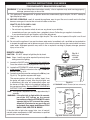
The Real-Fyre burner system is to be installed only in
a solid-fuel burning fireplace with a working flue and
constructed of noncombustible material.The installation,
including provisions for combustion and ventilation air
must conform with the National Fuel Gas Code, ANSI
Z223.1/NFPA 54, or the CSA B149.1, Natural Gas
and Propane Installation Code, and applicable local
building codes.
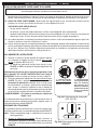
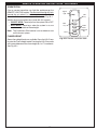
A damper clamp is included to maintain the minimum
permanent vent opening and to prevent full closure
of the damper blade. The chimney damper MUST
be fully opened when burning the unit. The unit is
designed to burn with yellow flames; thus adequate
ventilation is absolutely necessary.
To comply with certification, listings, and building
code acceptances, and for safe operation and proper
performance of this burner system, you must use ONLY
Peterson parts and accessories. Use of any other
controls, parts, or accessories not designed for use with
Real-Fyre burner systems is prohibited. This will void
all warranties, certifications, listings, and building code
approvals, and may cause property damage, personal
injury, or loss of life. Peterson will not be liable for any
damages caused by this misuse.
*Note: Solid-fuels shall not be burned in a fireplace
where a decorative appliance is installed.
Do not store or use gasoline or other
flammable vapors and liquids in the
vicinity of this or any other appliance.
WHAT TO DO IF YOU SMELL GAS:
• Open a window.
• Do not try to light any appliance.
• Do not touch any electrical switch; do
not use any phone in the building.
• Immediately call the gas supplier
from a neighbor’s phone. Follow gas
supplier’s instructions.
• If you cannot reach the gas supplier,
call the fire department.
Installation and service must be performed
by a qualified professional installer,
service agency, or the gas supplier.
This appliance is only for use with the type
of gas indicated on the rating plate.
INSTALLER:
Leave this manual with the appliance.
CONSUMER:
Retain this manual for future reference.
13-085
Robert H. Peterson Co. • 14724 East Proctor Avenue • City of Industry, CA 91746
REV 1 - 1502040950
1
L-A2-380
INSTALLATION ET
MODE D'EMPLOI
Systèmes De Brûleur:
CONCEPTION CERTIFIÉE
G52- ** -(P)A
G52- ** -17(P)
G52- ** -2V(P)A
à
Vented Decorative Appliance
ANSI Z21.60-2012
CSA 2.26-2012
** Tailles:
(18/20, 24/30)
POUR L'INSTALLATION DANS
LE COMBUSTIBLE SOLIDE DE
BRÛLANT FIREPLACES*
Système de brûleur
réglementé l'usage du
propane ou du gaz naturel
G52 VENTED BURNER SYSTEMS
IMPORTANT: L I S E Z C E S I N S T RU C T I O N S
SOIGNEUSEMENT AVANT DE
COMMENCER L'INSTALLATION DE
L'UNITÉ.
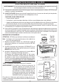
Le Vrai-Fyre système de brûleur doit être installée
seulement dans une cheminée brûlante de combustible
solide avec une conduite de cheminée fonctionnante
et être construit avec du matériel non-combustible.
L'installation, y compris des dispositions pour l'air de
combustion et de ventilation doit se conformer au code
national de gaz de carburant, la norme ANSI Z223.1/
NFPA 54, ou le CSA B149.1, code d'installation de gaz
naturel et de propane, et codes du bâtiment locaux
applicables.
Une bride plus humide est incluse pour maintenir
l’ouverture permanente minimum de passage et pour
empêcher la pleine fermeture de la lame plus humide.
L'amortisseur de cheminée DOIT être entièrement
ouvert en brûlant l'unité. L'unité est conçue pour
brûler avec les flammes jaunes; ainsi à ventilation
proportionnée est absolument nécessaire.
Pour se conformer à la certification, listings, et de
renforcement des acceptations de code, et pour un
fonctionnement sûr et une bonne performance de ce
système de brûleur, vous devez utiliser uniquement
des pièces et accessoires Peterson. L'utilisation
d'autres contrôles, de pièces ou accessoires non
conçu pour une utilisation avec les systèmes de
brûleurs Real-Fyre est interdite. Ceci annulera toutes
les garanties, les certifications, les annonces et les
approbations du code du bâtiment, et peut causer des
dommages matériels, des blessures ou des pertes de
vie. Peterson ne sera pas responsable des dommages
causés par ce détournement.
*Note: des Plein-carburants ne seront pas brûlés
dans une cheminée où un appareil décoratif
est installé.
AVERTISSEMENT
Si l’information en ce manuel n’est pas suivie
exactement, une incendie ou une explosion
peut résulter, entraînant des dégats
matériels, des blessures, ou la perte de la vie.
Ne stockez pas ou n’employez pas l’essence
ou d’autres vapeurs et liquides inflammables
à proximité de ceci ou d’aucun autre appareil.
CE QUI À FAIRE SI VOUS SENTEZ LE GAZ:
• Ouvrez une fenêtre.
• N’essayez pas de n’allumer aucun appareil.
• Ne touchez aucun commutateur
électrique; n’utilisez aucun téléphone
dans le bâtiment.
• Appelez immédiatement le fournisseur
de gaz du téléphone du voisin. Suivez les
instructions du fournisseur de gaz.
• Si vous ne pouvez pas atteindre le
fo u r n i s s e u r d e g a z , a p p e l e z l e
département de feu.
L’installation et le service doivent être assurés
par un installateur qualifié et professionnel,
l’agence de service, ou le fournisseur de gaz.
Cet appareil sert seulement avec le type de
gaz indiqué de la plaque de contrôle.
INSTALLATEUR :
Laissez ce manuel avec l'appareil.
CONSOMMATEUR:
Maintenez ce manuel pour la future référence.
13-085
Robert H. Peterson Co. • 14724 East Proctor Avenue • City of Industry, CA 91746
REV 1 - 1502040950
2
L-A2-380
TABLE OF CONTENTS
GETTING STARTED
IMPORTANT PRE-INSTALLATION AND FIREPLACE SAFETY INFORMATION ...............................5
SPECIFICATIONS AND DIMENSIONS......................................................................................................6
DAMPER CLAMP INSTRUCTIONS ...........................................................................................................8
BURNER PARTS LIST - MANUAL SERIES ..............................................................................................9
BURNER PARTS LIST - 17 SERIES ......................................................................................................... 10
BURNER PARTS LIST - 2VA SERIES .......................................................................................................11
LOGS PARTS LIST .................................................................................................................................... 12
INSTALLATION
INSTALLATION......................................................................................................................................... 14
BURNER INSTALLATION ...................................................................................................................... 14
LAVA GRANULES (DECORATIVE) ........................................................................................................ 15
SAND/VERMICULITE PLACEMENT...................................................................................................... 15
INITIAL GLOWING EMBERS PLACEMENT ........................................................................................... 15
LOG SET (& ADDITIONAL EMBERS) PLACEMENT .............................................................................. 16
INSTALLING/REPLACING BATTERIES (if applicable) ........................................................................ 20
REMOTE TRANSMITTER BATTERY ...................................................................................................... 20
REMOTE RECEIVER / SWITCH BOX BATTERIES .................................................................................. 20
USE, CARE, & SERVICE
LIGHTING INSTRUCTIONS - MANUAL SERIES ................................................................................. 21
LIGHTING THE PILOT ......................................................................................................................... 21
LIGHTING THE BURNER ..................................................................................................................... 23
SHUTTING DOWN ................................................................................................................................ 23
PILOT BURNER CHECK/ADJUSTMENT ............................................................................................... 23
LIGHTING INSTRUCTIONS - 17 SERIES .............................................................................................. 25
LIGHTING THE PILOT ......................................................................................................................... 25
REMOTE LIGHTING ............................................................................................................................. 25
MANUAL LIGHTING ............................................................................................................................. 27
SHUTTING DOWN ................................................................................................................................ 29
PILOT BURNER CHECK/ADJUSTMENT ............................................................................................... 29
REMOTE OPERATING INSTRUCTIONS - 17 SERIES .......................................................................... 29
ORIENTATION ...................................................................................................................................... 29
FLAME HEIGHT ................................................................................................................................... 29
LIGHTING INSTRUCTIONS - 2VA SERIES ........................................................................................... 31
REMOTE LIGHTING ............................................................................................................................. 31
MANUAL LIGHTING ............................................................................................................................. 33
SHUTTING DOWN ................................................................................................................................ 33
PILOT APPEARANCE ........................................................................................................................... 33
REMOTE OPERATING INSTRUCTIONS - 2VA SERIES ....................................................................... 35
ORIENTATION ...................................................................................................................................... 35
FLAME HEIGHT ................................................................................................................................... 35
CLEANING AND SERVICING ................................................................................................................. 37
TO CLEAN THE BURNER SYSTEM........................................................................................................ 37
FLAME DESCRIPTION ............................................................................................................................ 38
SYNCING THE REMOTE SYSTEM ......................................................................................................... 38
TROUBLESHOOTING .............................................................................................................................. 39
NOTES PAGE ............................................................................................................................................. 41
WARRANTY .............................................................................................................................................. 42
REV 1 - 1502040950
3
L-A2-380
L'INFORMATION DE SÛRETÉ IMPORTANTE DE PRÉINSTALLATION ET DE CHEMINÉE
ATTENTION:
L'installation et la réparation doivent être faites par un NFI certifié ou tout autre installateur professionnel qualifié.
Installateur:
A.
B.
C.
D.
E.
F.
G.
H.
I.
J.
K.
L.
M.
N.
O.
Lisez soigneusement ces instructions avant d'installer ce système de brûleur à gaz. Soyez sûr que vous comprenez
tous les mesures de sécurité et avertissements contenus en ce manuel.
Adultes doivent être présents lors de cet appareil au gaz est en marche. Cette unité ne doit pas être laissé sans surveillance
ou brûlure lorsque tout quelqu'un dort.
Cet appareil sert seulement avec le type de gaz indiqué de la plaque de contrôle. Cet appareil n'est pas CONVERTIBLE de
CHAMP pour l'usage avec d'autres gaz.
VÉRIFIEZ LE TYPE de GAZ (normal ou propane) : La fourniture de gaz doit être identique qu'indiquée de votre plaque de
contrôle de système de brûleur. Si la fourniture de gaz est différente, N'INSTALLEZ PAS. Contactez votre revendeur pour l'aide
immédiate.
FAITES ATTENTION: Sinon installé, entretenu, et utilisé correctement par ces instructions, ce produit peut causer le
dommage corporel, les dégats matériels, ou les pertes humaines sérieux.
AVERTISSEMENT: Avant l'installation dans une cheminée plein-carburant-brûlante, la conduite de cheminée, l'amortisseur, et
le foyer de cheminée doivent ÊTRE COMPLÈTEMENT NETTOYÉS de la suie, de la créosote, des cendres, et de la peinture
lâche, et doivent être inspectés par un décapant qualifié de cheminée. Quelques cheminées plus anciennes peuvent ont besoin
de réparation avant d'installer cet appareil.
Gardez le domaine du clair réglé de notation de gaz et libérez des matériaux combustibles, l'essence, et d'autres vapeurs et
liquides inflammables.
LA PRESSION DE GAZ INSUFFISANTE GARDERA LE PILOTE DU FONCTIONNEMENT CORRECTEMENT (SI ÉQUIPÉ).
N'EMPLOYEZ PAS SI LA PRESSION DE GAZ EST INFÉRIEURE À LA CONDITION MINIMUM.
L'admission minimum gaz-fournissent la pression aux fins de l'ajustement d'entrée est 5" ; colonne d'eau (w.c.) sur le gaz
naturel et le 11" ; w.c. sur le gaz de propane. La pression de gaz insuffisante affectera l'opération appropriée du pilote (si
équipé). N'installez pas cet appareil à gaz si la pression minimum n'est pas disponible. L'admission maximum gaz-fournissent
la pression est 10.5" ; w.c. sur le gaz naturel et le 13" ; w.c. sur le gaz de propane. La source de propane doit être réglée. (Ne
pas connecter cet appareil directement à un réservoir de gaz propane non -. Cela peut provoquer une explosion) Ne
pas brancher cet appareil à une bouteille de gaz propane portable.
Le système sifflant de gaz doit être classé pour fournir la pression d'admission minimum au débit maximum (BTU/hr).
La perte de pression anormale se produira si la pipe est trop petite, ou la course est trop longue. La pipe de fourniture de gaz
doit être 1/2" ; diamètre intérieur minimum. Si la ligne de gaz est plus longue que 20' ; une ligne de plus grand diamètre peut
être nécessaire. Reportez-vous aux directives NFPA 54 pour plus de détails.
Les estimations d'entrée montrées en Btu par heure sont pour des altitudes jusqu'à 2.000 pi. Pour des altitudes au-dessus de
2.000 pi, référez-vous au code national de gaz de carburant ou entrez en contact avec le fabricant avant d'installer ce produit.
Cet appareil à gaz et son clapet à gaz principal doivent être disconnected du gaz-fournissent le système sifflant pendant tout
vérificateur de pression de ce système aux pressions d'essai au-dessus de 1/2 psig.
Cet appareil à gaz doit être isolé dans gaz-fournissent le système sifflant en fermant le robinet d'isolement d'équipement relié
au gaz-fournissent la ligne pendant tout vérificateur de pression du gaz-fournissent le système sifflant aux pressions d'essai
égales à ou moins d'à 1/2 psig.
N'employez pas cet appareil si n'importe quelle partie a été sous-marine. Appelez immédiatement un technicien qualifié de service
pour inspecter l'appareil et pour remplacer n'importe quelle partie du système de contrôle et de n'importe quelle commande de
gaz qui a été sous-marine.
Una pantalla de la chimenea debe ser en el lugar cuando el sistema está quemando. Las provisiones para el aire de
combustión adecuado deben ser mantenidas. A menos que otras provisiones para el aire de combustión se proporcionen, la
pantalla tendrá una abertura para la introducción de aire de combustión. El aire de combustión es adecuado cuando todas las
llamas se encrespan en la chimenea y lejos de la pantalla. Cuando se utiliza un recinto de cristal de la chimenea (puerta),
deje las puertas completamente abiertas cuando el sistema es en funcionamiento.
Pour installer l'appareil à gaz dans votre foyer, la cheminée doit répondre aux exigences minimales de taille (voir tableau
minimum cheminée dimension en section CARACTÉRISTIQUES TECHNIQUES).
Cet appareil peut être installé dans un marché des accessoires, maison (mobile) de manière permanente située et manufacturée,
où non interdit par des codes locaux. L'installation des appareils a conçu pour la maison manufacturée (États-Unis seulement)
ou installation de caravane résidentielle doit se conformer au CAN/CSA standard Z240 MH, logement mobile, au Canada, ou à
la construction et au standard de sécurité à la maison manufacturés, intitulent 24 CFR, la partie 3280, aux Etats-Unis, ou quand
une telle norme ne s'applique pas, à ANSI/NCSBCS A225.1/NFPA 501A, installations à la maison manufacturées standard.
4
IMPORTANT PRE-INSTALLATION AND FIREPLACE SAFETY INFORMATION
CAUTION: Installation and repair must be done by an NFI Certified or other qualified professional installer.
Installer:
Carefully read these instructions before installing this gas burner system. Be sure you understand
all safety precautions and warnings contained in this manual.
A. Adults shall be present when this gas appliance is operating. This unit shall not be left burning when unattended or
while anyone is sleeping.
B. This appliance is only for use with the type of gas indicated on the rating plate.This appliance is NOT FIELD CONVERTIBLE
for use with other gasses.
CHECK GAS TYPE (natural or L.P.): The gas supply must be the same as stated on your burner system rating plate. If
gas supply is different, DO NOT INSTALL. Contact your dealer for immediate assistance.
C. BE CAREFUL: If not installed, serviced, and used correctly per these instructions, this product can cause serious
personal injury, property damage, or loss of life.
D. WARNING: Before installing in a solid-fuel-burning fireplace, the chimney flue, damper, and firebox must be thoroughly
CLEANED of soot, creosote, ashes, and loose paint, and must be inspected by a qualified chimney cleaner. Some older
fireplaces may need repair prior to installing this appliance.
E. Keep the area of the gas burner system clear and free from combustible materials, gasoline, and other flammable
vapors and liquids.
F. INSUFFICIENT GAS PRESSURE WILL KEEP THE PILOT (IF EQUIPPED) FROM OPERATING PROPERLY. DO NOT
USE IF GAS PRESSURE IS LOWER THAN THE MINIMUM REQUIREMENT.
G. The minimum inlet gas-supply pressure for purposes of input adjustment is 5" water column (w.c.) on natural gas and
11" w.c. on L.P. gas. Insufficient gas pressure will affect proper operation of the pilot (if equipped). Do not install this gas
appliance if minimum pressure is not available. The maximum inlet gas-supply pressure is 10.5" w.c. on natural gas and
13" w.c. on L.P. gas. The L.P. source must be regulated. (Do not connect this appliance directly to an unregulated
L.P. gas tank - this can cause an explosion.) Do not connect this appliance to a portable L.P. gas cylinder.
H. The gas piping system must be sized to provide minimum inlet pressure at the maximum flow rate (BTU/hr).
Undue pressure loss will occur if the pipe is too small, or the run is too long. Gas supply pipe must be 1/2" minimum
interior diameter. If the gas line is longer than 20', a larger diameter line may be necessary. Refer to the NFPA 54
guidelines for further details.
I. Input ratings shown in BTU per hour are for elevations up to 2,000 ft. For elevations above 2,000 ft., refer to the National
Fuel Gas Code or contact manufacturer before installing this product.
J. This gas appliance and its main gas valve must be disconnected from the gas-supply piping system during any pressure
testing of that system at test pressures in excess of 1/2 psig.
K. This gas appliance must be isolated from the gas-supply piping system by closing the equipment shutoff valve connected to
the gas-supply line during any pressure testing of the gas-supply piping system at test pressures equal to or less than 1/2 psig.
L. Do not use this appliance if any part has been underwater. Immediately call a qualified service technician to inspect the
appliance and to replace any part of the control system and any gas control that has been underwater.
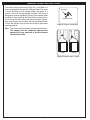
M. A fireplace screen must be in place when the system is burning. Provisions for adequate combustion air must be
maintained. Unless other provisions for combustion air are provided, the screen shall have an opening(s) for introduction
of combustion air. Combustion air is adequate when all flames curl into the fireplace and away from the screen. When
a glass fireplace enclosure (door) is used, leave the doors fully open when the system is in operation.
N. To install the gas appliance in your fireplace, the fireplace MUST meet the minimum size requirements (see
minimum fireplace dimension table in SPECIFICATIONS section).
O. This appliance may be installed in an aftermarket, permanently located, manufactured (mobile) home, where not prohibited
by local codes. Installation of appliances designed for manufactured home (U.S. only) or mobile home installation must
conform with the Standard CAN/CSA Z240 MH, Mobile Housing, in Canada, or with the Manufactured Home Construction
and Safety Standard, Title 24 CFR, Part 3280, in the United States, or when such a standard is not applicable, ANSI/
NCSBCS A225.1/NFPA 501A, Manufactured Home Installations Standard.
5
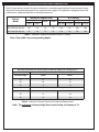
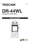
SPECIFICATIONS AND DIMENSIONS
Real-Fyre gas burner systems must be installed only in a wood burning fireplace with the minimum firebox
dimensions and venting requirements met (see table on this page). This appliance is designed to burn with
yellow flames; adequate ventilation is absolutely necessary.
Minimum Fireplace Size
Burner
Model
Width
Depth
Height
Front
Rear
G52-18/20
24"
20"
15"
G52-24/30 (24" log set)
32"
24"
G52-24/30 (30" log set)
34"
28"
BTU Rating
Low Setting
High Setting
Nat. Gas
L.P. Gas
Nat. Gas
L.P. Gas
16"
20k
18k
46k
36k
15"
16"
23k
21k
55k
46k
15"
16"
23k
21k
55k
46k
Table 1 - Minimum Fireplace Dimensions and BTU ratings
Note: Rear width is at corresponding depth.
Minimum permanent free opening area of chimney damper for venting (sq. in.)
For factory-built fireplaces
Chimney height
18/20"
24/30"
15'
21
24
20'
18
21
30'
14
16
For masonry-built fireplaces
15'
30
35
20'
27
32
30'
25
29
Table 2 - Minimum Chimney Damper Vent Opening Requirements
Note: The minimum chimney height from hearth to top of chimney is 15'.
6
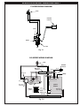
SPECIFICATIONS AND DIMENSIONS (cont.)
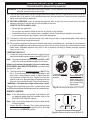
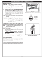
17 SERIES WIRING DIAGRAM
Pilot
Remote
receiver
Inlet
Outlet
Valve
Fig. 7-1
2VA SERIES WIRING DIAGRAM
Pilot
White
ON/OFF
Switch
Orange
Main wire
harness
Green
Brown
White
(Main out)
Black
Orange
(Pilot out)
Step motor
main flame
Brown
Main
(Inlet)
Ignition
module
Valve
Battery
pack
Red
Black
Motor wire
harness
Fig. 7-2
7
S
I
Main flame
step output
(GND)
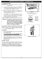
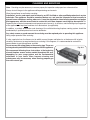
DAMPER CLAMP INSTRUCTIONS
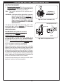
The damper clamp with hex bolt (Fig. 8-1) is provided as a
means to prevent full closure of the damper blade. The clamp
is easily attached to most damper blades with pliers or a
wrench, and must be permanently installed. The clamp is
designed to prevent accidental closure of the damper when
installed as illustrated (Fig. 8-2). Should the clamp not fit, or
fail to provide the permanent vent opening listed in Table 2,
have a permanent stop installed, remove the damper blade,
or have the damper cut to provide the minimum permanent
opening required.
Set screw
Damper clamp
Fig. 8-1 Damper clamp detail
Note: These are minimum damper opening specifications.
The damper must be completely opened when
operating this gas appliance to achieve the best
ventilation possible.
Open
Closed
Fig. 8-2 Damper open / closed
8
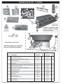
BURNER PARTS LIST - MANUAL SERIES
6
7
Pilot
8
5
Thermocouple
9
1
24/30" burner model shown
10
11
3
Note: Photos not to scale
2
Replacement parts can be ordered
from your local Real-Fyre dealer.
4
Bottom view
18/20" model
24/30" model
Description
Part No.
Qty.
Part No.
Qty.
1.
or
Pilot assembly (natural)
Pilot assembly (propane)
PAC-1NAT
PAC-1LP
1
1
PAC-1NAT
PAC-1LP
1
1
2.
Control valve (natural or propane models)
SV-19
1
SV-19
1
3.
Valve extension kit
(includes extension rod, knob, bracket & nut)
EH-12
1
EH-12
1
4.
Flex connector (w/ adapter), 1/2" O.D. x 24"
3035
1
3035
1
5.
Radiant booster grid
SC-10
1
SC-15
1
6.
Glowing embers A
EM-22A
1
EM-21A
1
7.
Glowing embers B
EM-22B
1
EM-21B
1
8.
Bryte coals
EM-11
1
EM-11
1
9.
or
Sand (natural gas)
Vermiculite (propane gas)
CS-4
LF-15-3.5
2
1
CS-10
LF-15-7
1
1
10.
Lava granules
LF-4
1
LF-4
1
11.
Damper clamp
DC-1
1
DC-1
1
Item
9
BURNER PARTS LIST - 17 SERIES
8
7
9
5
Pilot
4
Thermocouple
11
1
24/30" burner
model shown
10
12
Remote transmitter and
receiver batteries included
with burner system.
13
3
Note: Photos not to scale
Replacement parts can be ordered
from your local Real-Fyre dealer.
2
6
Bottom view
18/20" model
24/30" model
Description
Part No.
Qty.
Part No.
Qty.
1.
or
Pilot assembly (natural)
Pilot assembly (propane)
PAC-1NAT
PAC-1LP
1
1
PAC-1NAT
PAC-1LP
1
1
2.
Control valve (natural or propane models)
SV-37
1
SV-37
1
3.
Valve extension kit
(includes extension rod, knob, bracket & nut)
EH-12
1
EH-12
1
4.
Remote kit
(includes receiver, transmitter, batteries, plastic cover)
VR-1A
1
VR-1A
1
5.
Remote transmitter (only)
AT-V1-1
1
AT-V1-1
1
6.
Flex connector (w/ adapter), 1/2" O.D. x 24"
3035
1
3035
1
7.
Radiant booster grid
SC-10
1
SC-15
1
8.
Glowing embers A
EM-22A
1
EM-21A
1
9.
Glowing embers B
EM-22B
1
EM-21B
1
10.
Bryte coals
EM-11
1
EM-11
1
11.
or
Sand (natural gas)
Vermiculite (propane gas)
CS-4
LF-15-3.5
2
1
CS-10
LF-15-7
1
1
12.
Lava granules
LF-4
1
LF-4
1
13.
Damper clamp
DC-1
1
DC-1
1
Item
10
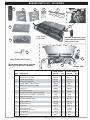
BURNER PARTS LIST - 2VA SERIES
9
12
11
10
8
Electrode
Pilot
Heat sensor
1
13
24/30" burner
model shown
14
Remote transmitter and
switch box batteries included
with burner system.
6
15
5
Note: Photos not to scale
7
4
Replacement parts can be ordered
from your local Real-Fyre dealer.
Item
2
3
Description
Bottom view
18/20" model
24/30" model
Part No.
Qty.
Part No.
Qty.
1.
or
Pilot assembly (natural)
Pilot assembly (propane)
PAC-9
PAC-9P
1
1
PAC-9
PAC-9P
1
1
2.
or
Control valve (natural)
Control valve (propane)
SV-47
SV-47P
1
1
SV-47
SV-47P
1
1
3.
Control module / remote receiver
IMP-4
1
IMP-4
1
4.
Main & motor harness assembly
WH-02
1
WH-02
1
5.
Battery box
BAT-02
1
BAT-02
1
6.
Switch box assembly
(includes battery box, switch, heat shield)
SBA-02
1
SBA-02
1
7.
Flex connector (w/ adapter), 1/2" O.D. x 24"
3035
1
3035
1
8.
Radiant booster grid
SC-10
1
SC-15
1
9.
Remote transmitter (only)
AT-2VA-1
1
AT-2VA-1
1
10.
Glowing embers A
EM-22A
1
EM-21A
1
11.
Glowing embers B
EM-22B
1
EM-21B
1
12.
Bryte coals
EM-11
1
EM-11
1
13.
or
Sand (natural gas)
Vermiculite (propane gas)
CS-4
LF-15-3.5
2
1
CS-10
LF-15-7
1
1
14.
Lava granules
LF-4
1
LF-4
1
15.
Damper clamp
DC-1
1
DC-1
1
11
LOGS PARTS LIST
Note: The log set is purchased and packaged separately.
EN(O,S)-18 Log Sets
Evergreen Oak (ENO)
Item Description
Charred Evergreen Split Oak (ENS)
Part No.
Qty.
Part No.
Qty.
1.
Rear log
ENOL-16BR
1
ENOL-16BR
1
2.
Front log (left & right pieces)
ENOL-18BF
1
ENSL-18BF
1
3.
Left middle log
ENOL-13TL
1
ENSL-12T
1
4.
Right middle log
ENOL-12T
1
ENSL-11T
1
5.
Center middle log
ENOL-8T
1
ENOL-8T
1
6.
Right top log
ENOL-13T
1
ENSL-13T
1
7.
Left top log
ENOL-7T
1
ENSL-9T
1
ENO-18
ENS-18
6
5
7
6
5
7
4
3
4
3
1
1
2
2
EN(O,S)-24 Log Sets
Evergreen Oak (ENO)
Item Description
Charred Evergreen Split Oak (ENS)
Part No.
Qty.
Part No.
Qty.
1.
Rear log
ENOL-21BR
1
ENOL-21BR
1
2.
Front log (left & right pieces)
ENOL-24BF
1
ENSL-24BF
1
3.
Left middle log
ENOL-15T
1
ENOL-15T
1
4.
Right middle log
ENOL-16T
1
FTSOL-14T
1
5.
Center middle log
ENOL-8T
1
ENOL-8T
1
6.
Center top log
ENOL-13T
1
ENSL-13T
1
7.
Left top log
ENOL-9T
1
ENSL-10T
1
ENO-24
ENS-24
6
7
6
7
5
4
3
5
4
3
1
1
2
2
12
LOGS PARTS LIST (cont.)
Note: The log set is purchased and packaged separately.
EN(O,S)-30 Log Sets
Evergreen Oak (ENO)
Item Description
Charred Evergreen Split Oak (ENS)
Part No.
Qty.
Part No.
Qty.
1.
Rear log
ENOL-23BR
1
ENOL-23BR
1
2.
Front log (left & right pieces)
ENOL-30BF
1
ENSL-30BF
1
3.
Left middle log
ENOL-15T
1
ENOL-15T
1
4.
Right middle log
ENOL-16T
1
FTSOL-14T
1
5.
Center middle log
ENOL-8T
1
ENOL-8T
1
6.
Left top log
ENOL-9T
1
ENSL-7T
1
7.
Right top log
ENOL-10T
1
ENSL-9T
1
8.
Center top log
ENOL-13T
1
ENSL-14TY
1
ENO-30
ENS-30
8
8
7
6
7
6
5
3
4
5
3
4
1
1
2
2
13
INSTALLATION
The Real-Fyre burner system must be installed by a qualified professional service technician. Instructions must
be followed carefully to ensure proper performance and full benefit from the burner system. Check to be sure
the burner system is designed and labeled for the type of gas (natural or propane gas) supplied to the
fireplace. Fireplace floor must be level, clean, and smooth.
WARNING: Failure to position the parts in accordance with these diagrams or failure to use only parts
specifically approved with this appliance may result in property damage or personal injury.
REFER TO THE PARTS LIST WHEN FOLLOWING INSTALLATION
INSTRUCTIONS.
24" 2VA burner model shown here.
Gas supply stub
Flex connector
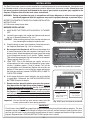
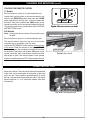
BURNER INSTALLATION
1. MAKE SURE THE FIREPLACE GAS SUPPLY IS TURNED
OFF.
Adapter
2. Locate the gas-supply stub inside the fireplace and remove
the cap, if attached (reference Fig. 14-1).
CAUTION:
When removing the cap, make sure the stub does not
turn, loosening the connection inside the wall.
Fig. 14-1 Connect gas supply
3. Place the burner system in the fireplace. Center the burner in
the fireplace. (Reference Fig. 14-2 for orientation.)
(2VA model shown here)
4. Be sure gas to the fireplace is off. Remove the adapter that
is loosely connected to the flex connector (coming off of the
burner system). Attach the adapter to the gas-supply stub using
a pipe compound resistant to all gasses. Tighten securely.
Then attach the open end of the flex connector to the adapter.
Tighten securely (see Fig. 14-1).
5. LEAK TEST: Turn on the fireplace gas supply, and test at
all connections for leaks using the appropriate soapy water
solution. If bubbles appear, a leak is present. Turn off the
gas and tighten at all connections. Repeat until no leaks are
present. If a leak persists, turn off the gas supply and contact
the local gas company or dealer. NEVER USE A FLAME TO
CHECK FOR LEAKS.
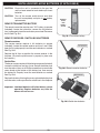
Fig. 14-2 Place switch box / receiver
Place switch box / receiver
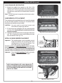
6. At this stage the burner system batteries are to be installed
(if applicable). Reference the INSTALLING/REPLACING
BATTERIES section for details.
7. Remote receiver: place the plastic cover over the receiver,
then place at the rear right corner of the fireplace. Place as
far from the burner system as possible. See Fig. 14-2 & Fig. 14-3.
Switch box: Place on its side, at the rear right corner of
the fireplace. It should rest with its bottom as near as possible
and facing the fireplace wall. It must not be placed directly
next to the burner pan area to avoid damage to the batteries.
See Fig. 14-2 & Fig. 14-3.
Important: Ensure that the box wire remains away from the
burner system and its flame during operation.
DO NOT
place box
in this area
Place switch box:
•
•
Rt rear corner,
on side,
exposed side against
fireplace wall
Place receiver:
•
•
Rt rear corner
Ensure plastic
cover is in place
Fig. 14-3 Proper box/receiver placement
IMPORTANT
For all valves, the air MUST be purged from the gas line before the pilot will light and burn properly. The time
needed to purge will depend on the length of the gas line to the unit and the amount of time since the unit or
gas line was last used. It may take several minutes before all the air is purged and the pilot will light and burn
properly. Reference the LIGHTING INSTRUCTIONS section in this manual.
14
INSTALLATION (cont.)
LAVA GRANULES (DECORATIVE)
1. Spread the supplied lava granules on the floor of the
fireplace, around the front and sides of the burner system
(see Fig. 15-1). The lava granules may be placed around
the switch box. Leave the front of the box clear for control
access.
Note: DO NOT place any lava granules on the burner system,
or behind it.
Fig. 15-1 Place lava granules
SAND/VERMICULITE PLACEMENT
The sand/vermiculite supplied with the unit is specially selected
for use with either propane or natural gas. It maximizes flame
distribution and reduces carbon buildup.
CAUTION: Use only sand for natural gas burners and
vermiculite for propane gas burners.
1. Fill the burner pan completely with the sand/vermiculite
(see Fig. 15-2). Avoid spilling the sand/vermiculite on
the pilot assembly.
2. Slope the sand/vermiculite at the same angle as the burner
pan. This is important to ensure quiet lighting and even
flame distribution. See Fig. 15-3.
Fig. 15-2 Place sand/vermiculite
INITIAL GLOWING EMBERS PLACEMENT
Important: The supplied embers are to be applied at several
stages of installation. You may end up with some
unused embers at the end of installation. If so,
store them for later use/replacement.
Sprinkle a portion of the glowing embers A lightly and evenly
over the entire surface of the sand/vermiculite as shown in Fig.
15-4. Break up any clumps that may have developed during
shipment. Store unused embers for later use/replacement.
Fill pan
with sand/
vermiculite
Fig. 15-3 Sand/vermiculite detail
Important: Place the glowing embers A lightly and evenly
exactly as shown. DO NOT over apply.
Place embers A exactly as shown
KEEP SAND/VERMICULITE, LAVA GRANULES,
AND ALL FOREIGN OBJECTS AWAY FROM THE
PILOT ASSEMBLY DURING MEDIA PLACEMENT
AND AT ALL TIMES.
Fig. 15-4 Place glowing embers A
KEEP CLEAR
Fig. 15-5 Keep pilot clear
15
INSTALLATION (cont.)
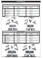
LOG SET (& ADDITIONAL EMBERS) PLACEMENT
You must position and maintain the log layout as shown here to ensure optimal operation of the burner system.
24" log set shown below for generic placement steps. Final steps are separated by log set size. ENO log sets
shown. Design may slightly vary; placement is the same.
CAUTION: BURN HAZARD! Logs will remain hot for some time after use. If you need to reposition
any log to maintain the proper layout, use heat-resistant gloves or allow logs adequate time
to cool before handling.
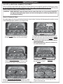
Generic Placement Steps
All models begin with the log and ember placement shown below. Continue with the appropriate section (on one
of the following pages) specific to your log set size.
1A
Ember stop
(part of frame)
1
Place embers B exactly as shown
Place the rear log (log #1) as shown.The log should
be slid back on the burner until it hits the backstop.
The ember stop at the front of the shelf serves to confine
the embers B in place. Place a level amount of embers
B on the shelf in front of the rear log exactly as shown.
• Pack the embers down (to reduce heat transfer to
components below).
• Save a small amount of embers for placement on
the radiant booster grid.
1C
1B
Place remaining embers B exactly as shown
Place the radiant booster grid as shown. The grid
should rest against the rear log. The ember stop
has notches to properly align the grid in place.
Place the remaining amount of embers B across
the grid exactly as shown.
2A
2
2
Gently compress the rear and front logs to create
a tight fit around the grid.
Place the left and right front log pieces (log #2) as shown.
The two logs should be touching and centered on the burner.
16
INSTALLATION (cont.)
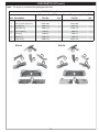
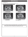
18" Log Sets Only
For 18" log sets, continue with the steps below to complete placement.
For 24" or 30" log sets, proceed to the following pages.
3
5
4
Place the left and right middle logs (logs #3 & #4)
as shown.
Place the center middle log (log #5) as shown.
6
7
Separate the bryte coals into small pieces and
evenly place them over the glowing embers in
the area shown.
Place the left and right top logs (logs #6 & #7)
as shown.
Note: The conditions/environment of each setup will slightly vary. After installation of your unit is
complete, follow the LIGHTING INSTRUCTIONS section to light the burner. The burner system
will reach optimal performance and appearance after approximately 20 minutes.
17
INSTALLATION (cont.)
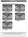
24" Log Sets Only
For 24" log sets, continue with the steps below to complete placement.
For 18" log sets, go back to the previous page. For 30" log sets, proceed to the following page.
3
5
4
Place the center middle log (log #5) as shown.
Place the left and right middle logs (logs #3 & #4)
as shown.
6
7
Place the center top log (log #6) as shown.
Place the left top log (log #7) as shown.
Separate the bryte coals into small pieces and
evenly place them over the glowing embers in
the area shown.
Note: The conditions/environment of each setup will slightly vary. After installation of your unit is
complete, follow the LIGHTING INSTRUCTIONS section to light the burner. The burner system
will reach optimal performance and appearance after approximately 20 minutes.
18
INSTALLATION (cont.)
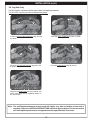
30" Log Sets Only
For 30" log sets, continue with the steps below to complete placement.
For 18" or 24" log sets, go back to the previous pages.
5
3
4
Place the left and right middle logs (logs #3 & #4)
as shown.
Place the center middle log (log #5) as shown.
8
7
6
Place the left and right top logs (logs #6 & #7)
as shown.
Place the center top log (log #8) shown.
Separate the bryte coals into small pieces and
evenly place them over the glowing embers in
the area shown.
Note: The conditions/environment of each setup will slightly vary. After installation of your unit is
complete, follow the LIGHTING INSTRUCTIONS section to light the burner. The burner system
will reach optimal performance and appearance after approximately 20 minutes.
19
INSTALLING/REPLACING BATTERIES (IF APPLICABLE)
CAUTION: Ensure the unit is connected to the gas line
and has been tested for leaks before you insert
batteries.
CAUTION: Turn off the remote and/or burner and allow
the unit to completely cool prior to any battery
replacements.
REMOTE TRANSMITTER BATTERY
The remote transmitter requires one "12V" battery to operate
(included). Locate the transmitter, remove the lid (found on
rear), and properly insert the new battery as marked. Re-secure
the lid. See Fig. 20-1.
REMOTE RECEIVER / SWITCH BOX BATTERIES
Remove
lid for
"12V"
battery
access
Fig. 20-1 Transmitter battery
Remote receiver
The remote receiver requires 4 AA batteries to operate
(included). Locate the remote receiver and turn it over. Slide
open the lid, and properly insert the new batteries as marked.
See Fig. 20-2.
"AA" batteries
Replace the lid, then re-position the remote receiver in the
fireplace. (Ensure the plastic cover is properly in place over
the receiver.)
Switch Box
The burner system requires 4 AA batteries to operate (included).
Locate the switch box and turn it over. Detach the battery box
from the velcro. Use a small Phillips screwdriver to remove the
screw found on the bottom of the battery box, then remove
the battery lid. Properly insert the new batteries as marked.
See Fig. 20-3.
Fig. 20-2 Remote receiver batteries
"AA" batteries
Replace the battery lid using the screw, replace the battery box
onto the velcro, and re-position the switch box in the fireplace.
Important: Low/dead batteries will affect burner system
operation. Replace batteries any time the
burner will not turn on.
Fig. 20-3 Switch box batteries
20
LIGHTING INSTRUCTIONS - MANUAL SERIES
FOR YOUR SAFETY READ BEFORE LIGHTING
WARNING: If you do not follow these instructions exactly, a fire or explosion may result causing property
damage, personal injury or loss of life.
A. Use only your hand to push in or turn the gas control knob. Never use tools. If the knob will not push in
or turn by hand, don't try to repair it. Call a qualified professional service technician. Excessive force or
attempted repair may result in fire or explosion.
B. BEFORE OPERATING, smell all around the appliance area for gas. Be sure to smell next to the floor
because some gas is heavier than air and will settle on the floor.
WHAT TO DO IF YOU SMELL GAS
• Do not light any appliance.
• Do not touch any electric switch; do not use any phone in your building.
• Immediately call your gas supplier from a neighbor's phone. Follow the gas supplier's instructions.
If you cannot reach your gas supplier, call the fire department.
C. The burner system has a pilot that can be lit by hand using a match or long-necked lighter. When lighting
the pilot, follow these instructions exactly.
D. Do not use this appliance if any part has been under water. Immediately call a qualified service technician
to inspect the appliance and to replace any part of the control system and any gas control which has been
under water. Attempted operation may result in fire or explosion resulting in property damage, personal
injury or loss of life.
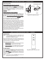
2. Turn the control knob counterclockwise to PILOT
(Fig. 21-1). Push the control knob firmly and fully in
and hold. Hold a long fireplace match or lighter near
the thermocouple to light the pilot. Continue to hold
the control knob in for approximately 60 seconds
after the pilot is lit, then release the knob. The pilot
will remain lit.
WARNING: If the pilot fails to light repeat steps 1
and 2.
If the pilot fails to light after several tries, turn the control
knob to OFF and contact a qualified professional service
technician.
21
1.
Turn knob
clockwise to OFF
prior to lighting
the pilot.
ON
PILOT
OFF
PILOT
ON
Allow five (5) minutes for any gas in the unit to dissipate.
IF YOU SMELL GAS, SEE STEP B ABOVE. If you don’t
smell gas, go on to step 2.
OFF
PILOT
ON
Note: The control knob cannot be turned from PILOT
to OFF unless the knob is pushed in slightly. Do
not force.
OFF
PILOT
1. Locate the valve on the side of the unit. Push in the
gas control knob slightly and turn clockwise to OFF
(Fig. 21-1).
OFF
LIGHTING THE PILOT
2.
Tu r n k n o b
counterclockwise to
PILOT position. With
match ready, press
knob in and hold for
60 seconds while
lighting pilot.
Fig. 21-1 Control knob detail (OFF, PILOT)
INSTRUCTIONS D'ALLUMAGE - SÉRIE MANUEL
POUR VOTRE SÉCURITÉ LISEZ AVANT D'ALLUMER
AVERTISSEMENT: Si vous ne suivez pas ces instructions à la lettre, un incendie ou une explosion entraînant
des dommages matériels, des blessures ou des pertes de vie.
A. N'utilisez que votre main pour enfoncer ou tourner le bouton de contrôle du gaz. Ne jamais utiliser d'outils. Si
le bouton ne sera pas enfoncer ou à tourner à la main, n'essayez pas de le réparer. Appelez un technicien
de service qualifié. Une force excessive ou une tentative de réparation pourrait provoquer un incendie ou
une explosion.
B. AVANT DE FAIRE FONCTIONNER, sentez autour de l'appareil pour le gaz. Assurez-vous de sentir près
du plancher, car certains gaz sont plus lourds que l'air et se déposent sur le sol.
QUE FAIRE SI UNE ODEUR DE GAZ
• Ne pas allumer l'appareil.
• Ne touchez à aucun interrupteur électrique; n'utilisez aucun téléphone dans votre bâtiment.
• Appelez immédiatement votre fournisseur de gaz à partir du téléphone d'un voisin. Suivez les instructions
du fournisseur de gaz. Si vous ne pouvez joindre votre fournisseur de gaz, appeler les pompiers.
C. Le système de brûleur a un pilote qui peut être allumée à la main à l'aide d'une allumette ou long cou léger.
Pour allumer la veilleuse, suivez ces instructions à la lettre.
D. Ne pas utiliser cet appareil si une partie quelconque a été submergée. Appelez immédiatement un technicien
de service qualifié pour inspecter l'appareil et pour remplacer toute pièce du système de contrôle et toute
commande de gaz qui a été sous l'eau. Tentative d'opération peut entraîner un incendie ou une explosion
entraînant des dommages matériels, des blessures ou des pertes de vie.
2. TTournez le bouton de réglage dans le sens antihoraire
pour PILOTE (Fig. 22-1). Appuyez sur le bouton de
commande fermement et pleinement enfoncée.Tenir
un long match de cheminée ou un briquet à proximité
du thermocouple pour allumer la veilleuse. Continuez
à tenir le bouton de commande pendant environ 60
secondes après que le pilote est allumé, puis relâchez
le bouton. Le pilote reste allumé.
AVERTISSEMENT: Si le pilote ne s'allume pas, répétez
les étapes 1 et 2.
Si la télécommande ne fonctionne pas, et des batteries avec
un niveau de puissance adéquate sont installés, reportezvous à la synchronisation des section REMOTE.
22
1. Tourner le bouton
dans le sens horaire
en position OFF avant
d'allumer la veilleuse.
ON
PILOT
OFF
PILOT
ON
Attendez cinq (5) minutes pour n'importe quel gaz dans
l'unité de se dissiper. S'IL YA UNE ODEUR DE GAZ,
voir l'étape B CI-DESSUS. Si vous ne sentez pas de gaz,
passez à l'étape 2.
OFF
PILOT
PILOTE
ON
Note: Le bouton de commande ne peut être activée à
partir PILOTE sur OFF si le bouton est enfoncé
légèrement. Ne pas forcer.
OFF
OFF
PILOT
1. Localiser la vanne sur le côté de l'appareil. Appuyer
sur le bouton légèrement de contrôle du gaz et tourner
dans le sens horaire à OFF (Fig. 22-1).
FF
ALLUMAGE DU PILOTE
2. Tournez le bouton
vers la position PILOT.
Avec une allumette
prêt, appuyez sur le
bouton et maintenez
pendant 60 secondes
tandis que d'allumer
la veilleuse.
Fig. 22-1 Détail bouton de commande
(OFF, PILOTE)
LIGHTING INSTRUCTIONS - MANUAL SERIES (cont.)
LIGHTING THE BURNER
ON
OFF
ON
PILOT
WARNING: If the burner fails to light within 5 seconds,
turn the control knob clockwise to
PILOT. Allow five (5) minutes for any
gas in the unit to dissipate, then repeat
step 2 above. IF YOU SMELL GAS, SEE
STEP B AT BEGINNING OF LIGHTING
INSTRUCTIONS.
ON
PILOT
OFF
PILOT
Note: The ignition sequence will take approximately
5
seconds.
OFF
1. Ensure the pilot is burning. Turn the gas control knob
counterclockwise to ON (Fig. 23-1) to ignite the burner.
The valve will open and the burner will light.
For Manual
Lighting, turn knob
counterclockwise to
ON position.
Fig. 23-1 Control knob detail (ON)
Pilot adjustment screw
ON
If the burner fails to light after several tries, push in the
control knob slightly and turn clockwise to OFF, and contact
a qualified professional service technician.
Thermocouple
SHUTTING DOWN
MAIN BURNER ONLY (pilot will remain lit):
Turn the control knob clockwise to PILOT.
BURNER AND PILOT (total shutdown):
PILOT
If you do not plan on using your burner system for an
extended period (one week or more), you may extinguish
the pilot. This will conserve energy and save you money.
Push in the control knob slightly and turn clockwise to OFF.
PILOT BURNER CHECK/ADJUSTMENT
With the pilot burner lit and the control knob in the pilot
position, check the pilot system for proper flame size and
appearance (see Fig. 23-2). The pilot adjustment screw is
located on the front of the gas valve (see Fig. 23-2). Using a
small flat head screwdriver, adjust the pilot screw to properly
size the flames. Turning the screw clockwise will lower the
flames, and turning it counterclockwise will raise them. Be
careful not to back the screw out of its threads.
The pilot flame should be a quiet, soft blue flame with yellow
tipping that encircles the thermocouple tip.
23
VALVE
Fig. 23-2 Pilot adjustment detail
INSTRUCTIONS D'ALLUMAGE - SÉRIE MANUEL (SUITE)
Note: La séquence d'allumage dure environ 5 secondes.
WARNING: Si le brûleur ne s'allume pas dans
les 5 secondes, tournez le bouton de
commande vers la droite pour PILOT.
Permettre aux cinq (5) minutes pour tout
gaz de l'unité de dissiper, puis répétez
l'étape 2 ci-dessus. SI VOUS UNE ODEUR
DE GAZ, voir l'étape B AU DÉBUT DE
instructions d'allumage.
ON
SUR
ON
PILOT
OFF
ON
PILOT
1. Assurer la veilleuse est allumée.Tournez le bouton de
contrôle du gaz dans le sens antihoraire sur ON (Fig.
24-3) pour allumer le brûleur.
OFFLa vanne s'ouvre et le
PILOT
brûleur s'allume.
OFF
ALLUMER LE BRÛLEUR
Pour l'éclairage
manuel, tournez
le bouton dans le
sens antihoraire à la
position ON.
Fig. 24-1 Détail bouton de commande (SUR)
Vis de réglage de
ON
Si le brûleur ne s'allume pas après plusieurs tentatives,
appuyez sur le bouton de commande et tournez légèrement
à OFF et contactez un technicien qualifié.
Thermocouple
ARRÊT
BRULEUR SEULEMENT (pilote reste allumé):
Tournez le bouton de commande vers la droite pour PILOT.
BRÛLEUR ET LA VEILLEUSE (arrêt total):
PILOTE
Si vous ne prévoyez pas d'utiliser votre système de brûleur
pour une longue période (une semaine ou plus), vous
pouvez éteindre le pilote. Ce sera de conserver l'énergie
et économiser de l'argent.
Enfoncez légèrement le bouton de commande et tournez
dans le sens horaire sur OFF.
VEILLEUSE CONTROLE/REGLAGE
Avec le brûleur de la veilleuse allumée et le bouton de
commande dans le poste de pilotage, vérifier le système
de pilotage de la taille de la flamme correspondant et
l'apparence (voir Fig. 24-1). La vis de réglage de la veilleuse
se trouve sur la face de la soupape à gaz (voir Fig. 24-1).
L'aide d'un petit tournevis à tête plate, ajustez la vis de la
veilleuse pour dimensionner correctement les flammes.
Tourner la vis dans le sens horaire réduira les flammes, et
en tournant dans le sens antihoraire leur susciterai. Veillez
à ne pas desserrer la vis de ses fils.
La flamme de la veilleuse devrait être tranquille, flamme
bleu pâle avec des pointes jaunes qui entoure la pointe du
thermocouple.
24
VANNE
Fig. 24-2 Détail réglage de la veilleuse
LIGHTING INSTRUCTIONS - 17 SERIES
FOR YOUR SAFETY READ BEFORE LIGHTING
WARNING: If you do not follow these instructions exactly, a fire or explosion may result causing property
damage, personal injury or loss of life.
A. Use only your hand to push in or turn the gas control knob. Never use tools. If the knob will not push in or turn
by hand, don't try to repair it. Call a qualified professional service technician. Excessive force or attempted
repair may result in fire or explosion.
B. BEFORE OPERATING, smell all around the appliance area for gas. Be sure to smell next to the floor
because some gas is heavier than air and will settle on the floor.
WHAT TO DO IF YOU SMELL GAS
• Do not light any appliance.
• Do not touch any electric switch; do not use any phone in your building.
• Immediately call your gas supplier from a neighbor's phone. Follow the gas supplier's instructions.
If you cannot reach your gas supplier, call the fire department.
C. The burner system has a pilot that can be lit by hand using a match or long-necked lighter. When lighting
the pilot, follow these instructions exactly.
D. Do not use this appliance if any part has been under water. Immediately call a qualified service technician
to inspect the appliance and to replace any part of the control system and any gas control which has been
under water. Attempted operation may result in fire or explosion resulting in property damage, personal
injury or loss of life.
LIGHTING THE PILOT
WARNING: If the pilot fails to light repeat steps 1 and 2.
If the pilot fails to light after several tries, turn the control knob
to OFF and contact a qualified professional service technician.
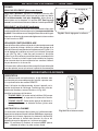
1. Turn knob clockwise
to OFF prior to lighting
the pilot.
OFF
2.
Tu r n k n o b
counterclockwise to
PILOT position. With
match ready, press
knob in and hold for
60 seconds while
lighting pilot.
Fig. 25-1 Control knob detail (OFF, PILOT)
REMOTE LIGHTING
Note: If the remote does not function, and batteries with
an adequate power level are installed, refer to the
SYNCING THE REMOTE section.
LEARN
Note: Step 1 may not be required if previously done during
an earlier lighting.
1. Ensure the pilot is burning. Then locate the 3-position
switch on the remote receiver (see Fig. 25-2), and slide
the switch to the REMOTE position.
OFF REMOTE
ON
Fig. 25-2 Remote receiver detail (REMOTE)
25
ON
PILOT
PILOT
ON
2. Turn the control knob counterclockwise to PILOT (Fig.
25-1). Push the control knob firmly and fully in and
hold. Hold a long fireplace match or lighter near the
thermocouple to light the pilot. Continue to hold the
control knob in for approximately 60 seconds after the
pilot is lit, then release the knob. The pilot will remain lit.
OFF
PILOT
Allow five (5) minutes for any gas in the unit to dissipate.
IF YOU SMELL GAS, SEE STEP B ABOVE. If you don’t smell
gas, go on to step 2.
ON
Note: The control knob cannot be turned from PILOT to OFF
unless the knob is pushed in slightly. Do not force.
PILOT
OFF
F
1. Locate the valve on the side of the unit. Push in the gas
control knob slightly and turn clockwise to OFF (Fig. 25-1).
INSTRUCTIONS D'ALLUMAGE - 17 SÉRIE
POUR VOTRE SÉCURITÉ LISEZ AVANT D'ALLUMER
AVERTISSEMENT: Si vous ne suivez pas ces instructions à la lettre, un incendie ou une explosion entraînant
des dommages matériels, des blessures ou des pertes de vie.
A. N'utilisez que votre main pour enfoncer ou tourner le bouton de contrôle du gaz. Ne jamais utiliser d'outils. Si le
bouton ne sera pas enfoncer ou à tourner à la main, n'essayez pas de le réparer. Appelez un technicien de service
qualifié. Une force excessive ou une tentative de réparation pourrait provoquer un incendie ou une explosion.
B. AVANT DE FAIRE FONCTIONNER, sentez autour de l'appareil pour le gaz. Assurez-vous de sentir près du
plancher, car certains gaz sont plus lourds que l'air et se déposent sur le sol.
QUE FAIRE SI UNE ODEUR DE GAZ
• Ne pas allumer l'appareil.
• Ne touchez à aucun interrupteur électrique; n'utilisez aucun téléphone dans votre bâtiment.
• Appelez immédiatement votre fournisseur de gaz à partir du téléphone d'un voisin. Suivez les instructions du
fournisseur de gaz. Si vous ne pouvez joindre votre fournisseur de gaz, appeler les pompiers.
C. Le système de brûleur a un pilote qui peut être allumée à la main à l'aide d'une allumette ou long cou léger. Pour
allumer la veilleuse, suivez ces instructions à la lettre.
D. Ne pas utiliser cet appareil si une partie quelconque a été submergée. Appelez immédiatement un technicien de
service qualifié pour inspecter l'appareil et pour remplacer toute pièce du système de contrôle et toute commande
de gaz qui a été sous l'eau. Tentative d'opération peut entraîner un incendie ou une explosion entraînant des
dommages matériels, des blessures ou des pertes de vie.
ALLUMAGE DE LA VEILLEUSE
AVERTISSEMENT: Si le pilote ne s'allume pas, répétez les
étapes 1 et 2.
Si la télécommande ne fonctionne pas, et des batteries avec un
niveau de puissance adéquate sont installés, reportez-vous à la
synchronisation des section REMOTE.
1. Tourner le bouton
dans le sens horaire
en position OFF avant
d'allumer la veilleuse.
OFF
2. Tournez le bouton
vers la position PILOT.
Avec une allumette
prêt, appuyez sur le
bouton et maintenez
pendant 60 secondes
tandis que d'allumer
la veilleuse.
Fig. 26-1 Détail bouton de commande
(OFF, PILOTE)
LEARN
DISTANCE DE L'ÉCLAIRAGE
Si la télécommande ne fonctionne pas, et que les batteries sont
installées, reportez-vous à la synchronisation des section REMOTE.
Note: Étape 1 ne peut être exigé s'il a déjà été fait au cours d'un
éclairage plus tôt.
1. Assurer la veilleuse est allumée. Ensuite, localisez le
commutateur à 3 positions sur le récepteur de la télécommande
(voir Fig. 26-2), Et faites glisser le commutateur sur la position
REMOTE.
26
ON
PILOT
PILOT
ON
2. Tournez le bouton de réglage dans le sens antihoraire pour
PILOTE (Fig. 26-1). Appuyez sur le bouton de commande
fermement et pleinement enfoncée. Tenir un long match
de cheminée ou un briquet à proximité du thermocouple
pour allumer la veilleuse. Continuez à tenir le bouton de
commande pendant environ 60 secondes après que le pilote
est allumé, puis relâchez le bouton. Le pilote reste allumé.
OFF
ON
Attendez cinq (5) minutes pour n'importe quel gaz dans l'unité
de se dissiper. S'IL YA UNE ODEUR DE GAZ, voir l'étape B
CI-DESSUS. Si vous ne sentez pas de gaz, passez à l'étape 2.
PILOT
PILOTE
PILOT
Note: Le bouton de commande ne peut être activée à partir
PILOTE sur OFF si le bouton est enfoncé légèrement. Ne
pas forcer.
OFF
OFF
FF
1. Localiser la vanne sur le côté gauche de l'appareil. Appuyer
sur le bouton de contrôle du gaz et tourner dans le sens
horaire en position OFF (Fig. 26-1).
OFF REMOTE
ON
Fig. 26-2 Détail récepteur de télécommande
(REMOTE)
LIGHTING INSTRUCTIONS - 17 SERIES (cont.)
2. Locate the remote transmitter and press and hold the
ON/HI button (see Fig. 27-1). The ignition sequence
will begin.
Note: Continue holding the button to increase the flame.
A click will be heard when max flame height is
reached.
ON/HI
LO/OFF
Note: Upon initial use or after an extended period of no
use, the ON/HI button may have to be pressed for
up to 3 seconds prior to functioning.
The remote receiver will emit an audible "beep";
then the valve will automatically open and the burner
will light. Adjust to the desired setting(s) with the
remote transmitter. See the REMOTE OPERATING
INSTRUCTIONS section for details.
Note: The ignition sequence will take approximately 5
seconds.
Fig. 27-1 Remote transmitter detail
WARNING: If the burner fails to light within 5 seconds,
press and hold the OFF button on the
remote transmitter and/or slide the switch
to the OFF position. Allow five (5) minutes
for any gas in the unit to dissipate, then
repeat steps 1 and 2 above. IF YOU SMELL
GAS, SEE STEP B AT BEGINNING OF
LIGHTING INSTRUCTIONS.
1. Ensure the pilot is burning. Then locate the 3-position
switch on the remote receiver (see Fig. 27-2), and slide
the switch to the OFF position.
OFF
PILOT
PILOT
counterclockwise to ON
ON
OFF
2. Turn the gas control knob
(Fig. 27-3) to ignite the burner. The valve will open and
the burner will light.
ON
Note: The ignition sequence will take approximately 5
seconds.
WARNING: If the burner fails to light within 5 seconds,
turn the control knob clockwise to
PILOT. Allow five (5) minutes for any
gas in the unit to dissipate, then repeat
step 2 above. IF YOU SMELL GAS, SEE
STEP B AT BEGINNING OF LIGHTING
INSTRUCTIONS.
If the burner fails to light after several tries, push in the
control knob slightly and turn clockwise to OFF, and contact
a qualified professional service technician.
27
ON
Fig. 27-2 Remote receiver (OFF for Manual Light)
ON
ON
PILOT
MANUAL LIGHTING
OFF REMOTE
OFF
If the burner fails to light after several tries, turn all system
components to OFF and contact a qualified professional
service technician.
LEARN
For Manual
Lighting, turn knob
counterclockwise to
ON position.
Fig. 27-3 Control knob detail (ON)
INSTRUCTIONS D'ALLUMAGE - 17 SÉRIE (cont.)
2. Localiser la télécommande et appuyez sur le bouton
ON/HI (voir Fig. 28-1). La séquence d'allumage
commence.
Note: Continuez à maintenir le bouton pour augmenter la
flamme. Un clic se fait entendre lorsque la hauteur
max de flamme est atteinte.
ON/HI
LO/OFF
Note: Dès la première utilisation ou après une longue
période de non utilisation, le bouton ON/HI
peut être pressée pour 3 secondes avant de
fonctionnement.
Le récepteur de la télécommande émettra un «bip»
sonore, puis la vanne s'ouvre automatiquement et le
brûleur s'allume. Choisissez le réglage souhaité (s) avec
la télécommande. Voir la section INSTRUCTIONS DE
FONCTIONNEMENT A DISTANCE pour plus de détails.
Si le brûleur ne s'allume pas après plusieurs essais, tournez
tous les composants du système à OFF et contactez un
technicien qualifié.
ALLUMAGE MANUEL
OFF
ON
PILOT
1. Assurer la veilleuse est allumée. Ensuite, localisez
OFFsur le récepteur de la
le commutateur à 3 positions
PILOT
télécommande (voir Fig. 28-2), Et faites glisser
le
commutateur sur la position OFF.
2. Tournez le bouton de contrôle du gaz dans le sens
antihoraire sur ON (Fig. 28-3) pour allumer le brûleur.
La vanne s'ouvre et le brûleur s'allume.
ON
Note: La séquence d'allumage dure environ 5 secondes.
WARNING: Si le brûleur ne s'allume pas dans
les 5 secondes, tournez le bouton de
commande vers la droite pour PILOT.
Permettre aux cinq (5) minutes pour tout
gaz de l'unité de dissiper, puis répétez
l'étape 2 ci-dessus. SI VOUS UNE ODEUR
DE GAZ, voir l'étape B AU DÉBUT DE
instructions d'allumage.
Si le brûleur ne s'allume pas après plusieurs tentatives,
appuyez sur le bouton de commande et tournez légèrement
à OFF et contactez un technicien qualifié.
28
LEARN
OFF REMOTE
ON
Fig. 28-2 Récepteur de la télécommander
(OFF pour Light Manuel)
ON
SUR
ON
PILOT
WARNING: Si le brûleur ne s'allume pas dans les
5 secondes, appuyez et maintenez le
bouton OFF de la télécommande et /
ou faites glisser le commutateur à la
position OFF. Permettre aux cinq (5)
minutes pour tout gaz dans l'unité à se
dissiper, puis répétez les étapes 1 et 2
ci-dessus. SI VOUS UNE ODEUR DE GAZ,
voir l'étape B AU DÉBUT DE DIRECTIVES
D'ALLUMAGE.
Fig. 28-1 Détail télécommande
OFF
Note: La séquence d'allumage dure environ 5 secondes.
Pour l'éclairage
manuel, tournez
le bouton dans le
sens antihoraire à la
position ON.
Fig. 28-3 Détail bouton de commande (SUR)
LIGHTING INSTRUCTIONS - 17 SERIES (cont.)
SHUTTING DOWN
Pilot adjustment screw
MAIN BURNER ONLY (pilot will remain lit):
Thermocouple
For remote shut down, press and hold the LO/OFF button
on the remote transmitter until the burner shuts off. If remote
is unavailable, slide the switch on the receiver to the OFF
position. For manual shutdown, turn the control knob
clockwise to PILOT.
BURNER AND PILOT (total shutdown):
If you do not plan on using your burner system for an
extended period (one week or more), you may extinguish
the pilot. This will conserve energy and save you money.
PILOT
VALVE
Fig. 29-1 Pilot adjustment detail
Push in the control knob slightly and turn clockwise to OFF.
PILOT BURNER CHECK/ADJUSTMENT
With the pilot burner lit and the control knob in the pilot
position, check the pilot system for proper flame size and
appearance (see Fig. 29-1). The pilot adjustment screw is
located on the front of the gas valve (see Fig. 29-1). Using a
small flat head screwdriver, adjust the pilot screw to properly
size the flames. Turning the screw clockwise will lower the
flames, and turning it counterclockwise will raise them. Be
careful not to back the screw out of its threads.
The pilot flame should be a quiet, soft blue flame with yellow
tipping that encircles the thermocouple tip.
REMOTE OPERATING INSTRUCTIONS - 17 SERIES
ORIENTATION
Note: If the remote does not function, and batteries with
an adequate power level are installed, refer to the
SYNCING THE REMOTE section.
Prior to remote transmitter use, light the appliance per the
REMOTE LIGHTING section. Familiarize yourself with the
transmitter buttons, as illustrated in Fig. 29-2.
ON/HI
LO/OFF
Identify the transmitter buttons:
• ON/HI BUTTON: This button turns the burner ON (when
the pilot is lit), and increases the flame height.
• LO/OFF BUTTON: This button decreases the flame
height and turns the burner OFF (pilot will remain lit).
FLAME HEIGHT
The flame height may be adjusted via the remote transmitter.
Press and hold the ON/HI button to increase the flame
height. Press and hold the LO/OFF button to decrease the
flame height. A click will be heard when the max/minimum
setting is reached.
Note: Continuing to hold the LO/OFF button will turn off
the burner. The pilot will remain lit.
29
Fig. 29-2 Remote transmitter detail
INSTRUCTIONS D'ALLUMAGE - 17 SÉRIE (cont.)
FERMER
Vis de réglage de
BRULEUR SEULEMENT (pilote reste allumé):
Pour arrêt à distance, appuyez et maintenez le bouton LO /
OFF sur la télécommande jusqu'à ce que le brûleur est éteint.
Si la télécommande n'est pas disponible, faites glisser le
commutateur sur le récepteur à la position OFF. Pour un arrêt
manuel, tournez le bouton de commande vers la droite pour PILOT.
Thermocouple
BRÛLEUR ET LA VEILLEUSE (arrêt total):
Si vous ne prévoyez pas d'utiliser votre système de brûleur pour
une longue période (une semaine ou plus), vous pouvez éteindre
le pilote. Ce sera de conserver l'énergie et économiser de l'argent.
PILOTE
VANNE
Fig. 30-1 Détail réglage de la veilleuse
Appuyer sur le bouton de commande légèrement et tournez dans
le sens horaire sur OFF.
VEILLEUSE CONTROLE/REGLAGE
Avec le brûleur de la veilleuse allumée et le bouton de commande
dans le poste de pilotage, vérifier le système de pilotage de la
taille de la flamme correspondant et l'apparence (voir Fig. 30-1). La
vis de réglage de la veilleuse se trouve sur la face de la soupape
à gaz (voir Fig. 30-1). L'aide d'un petit tournevis à tête plate,
ajustez la vis de la veilleuse pour dimensionner correctement les
flammes. Tourner la vis dans le sens horaire réduira les flammes,
et en tournant dans le sens antihoraire leur susciterai. Veillez à
ne pas desserrer la vis de ses fils.
La flamme de la veilleuse devrait être tranquille, flamme bleu pâle
avec des pointes jaunes qui entoure la pointe du thermocouple.
MODE D'EMPLOI À DISTANCE
ORIENTATION
Si la télécommande ne fonctionne pas, et des batteries avec
un niveau de puissance adéquate sont installés, reportez-vous
à la synchronisation des section REMOTE.
Avant l'utilisation de télécommande, allumer l'appareil par la
section de distance de l'éclairage. Familiarisez-vous avec les
boutons de l'émetteur, comme illustré sur la Fig. 30-2.
ON/HI
LO/OFF
Identifier les boutons de l'émetteur:
• TOUCHE ON/HI: Ce bouton active le brûleur ON (lorsque
le pilote est allumé), et augmente la hauteur de la flamme.
• TOUCHE LO/OFF: Cette touche permet de diminuer la
hauteur des flammes et éteindre l'brûleur (pilote reste
allumé).
HAUTEUR DE LA FLAMME
La hauteur de flamme peut être ajustée via la télécommande.
Appuyez et maintenez enfoncé le bouton ON / HI pour augmenter
la hauteur de la flamme. Appuyez et maintenez le bouton LO/
OFF pour diminuer la hauteur des flammes. Un clic se fait
entendre lorsque le réglage max / minimum est atteint.
Note: En continuant à maintenir le bouton LO/OFF permet
d'éteindre le brûleur. Le pilote restera allumé.
30
Fig. 30-2 Détail télécommande
LIGHTING INSTRUCTIONS - 2VA SERIES
FOR YOUR SAFETY READ BEFORE LIGHTING
WARNING: If you do not follow these instructions exactly, a fire or explosion may result causing property
damage, personal injury or loss of life.
A. This appliance is equipped with an ignition device that automatically lights the pilot. DO NOT attempt to
light the pilot by hand.
B. BEFORE OPERATING, smell all around the appliance area for gas. Be sure to smell next to the floor
because some gas is heavier than air and will settle on the floor.
WHAT TO DO IF YOU SMELL GAS
• Do not light any appliance.
• Do not touch any electric switch; do not use any phone in your building.
• Immediately call your gas supplier from a neighbor's phone. Follow the gas supplier's instructions.
If you cannot reach your gas supplier, call the fire department.
C. Use only the control system or remote to light the pilot. This valve will not operate if the pilot is not lit and
stable.
D. Do not use this appliance if any part has been under water. Immediately call a qualified service technician
to inspect the appliance and to replace any part of the control system and any gas control which has been
under water. Attempted operation may result in fire or explosion resulting in property damage, personal
injury or loss of life.
ON
REMOTE LIGHTING
Fig. 31-1
I
O
CAUTION: DO NOT attempt to light the pilot by hand.
Note: Steps 1 and 2 may not be required if previously done
during an earlier lighting.
Switch box,
ON/OFF
switch detail
OFF
1. Locate the ON/OFF switch at the front of the switch box.
Press the switch to the OFF (O) position. See Fig. 31-1.
Remote receiver
2. Locate the OFF/REMOTE switch actuator on the left rear
of the burner. Slide the actuator to the right / REMOTE
position. See Fig. 31-2.
3. Locate the remote transmitter and press the ON key (see
Fig. 31-3). The ignition sequence will begin.
The remote receiver will emit an audible "beep"; then
the igniter will begin to spark. After the pilot lights and
is established, the valve will automatically open and
the burner will light. Adjust to the desired setting with
the remote transmitter. See the REMOTE OPERATING
INSTRUCTIONS section for details.
Note: The ignition sequence will take approximately 5
seconds.
WARNING: If the pilot fails to light within 10 seconds,
press the OFF button on the remote
transmitter or slide the OFF/REMOTE switch
actuator (left) to OFF to turn off the system.
Allow five (5) minutes for any gas in the unit
to dissipate, then repeat step 2 above. IF YOU
SMELL GAS, SEE STEP B ABOVE.
If the pilot fails to light after several tries, turn all control/
remote system components to OFF and contact a qualified
professional service technician.
31
Fig. 31-2
OFF/REMOTE switch actuator (left rear of burner)
Signal
light
ON
key
ON
OFF
key
OFF
HI
LO
N/A
HI/LO
flame
adjustment
key
ON/OFF
Continuous Pilot
Fig. 31-3 Remote transmitter detail
INSTRUCTIONS D'ALLUMAGE - 2VA SÉRIE
POUR VOTRE SÉCURITÉ LISEZ AVANT D'ALLUMER
AVERTISSEMENT: Si vous ne suivez pas ces instructions à la lettre, un incendie ou une explosion entraînant
des dommages matériels, des blessures ou des pertes de vie.
A. Cet appareil est équipé d'un dispositif d'allumage qui allume automatiquement la veilleuse. NE PAS essayer
d'allumer la veilleuse manuellement.
B. AVANT D'UTILISER, Sentez tout autour de l'appareil pour le gaz. Assurez-vous de sentir près du plancher,
car certains gaz sont plus lourds que l'air et se déposent sur le sol.
QUE FAIRE SI UNE ODEUR DE GAZ
• Ne pas allumer l'appareil.
• Ne touchez à aucun interrupteur électrique; n'utilisez aucun téléphone dans votre bâtiment.
• Appelez immédiatement votre fournisseur de gaz à partir du téléphone d'un voisin. Suivez les instructions
du fournisseur de gaz. Si vous ne pouvez joindre votre fournisseur de gaz, appeler les pompiers.
C. Utilisez uniquement le système de commande ou de la télécommande pour allumer la veilleuse. Cette valve
ne fonctionne pas si le pilote n'est pas éclairé et stable.
D. Ne pas utiliser cet appareil si une partie quelconque a été submergée. Appelez immédiatement un technicien
de service qualifié pour inspecter l'appareil et pour remplacer toute pièce du système de contrôle et toute
commande de gaz qui a été sous l'eau. Tentative d'opération peut entraîner un incendie ou une explosion
entraînant des dommages matériels, des blessures ou des pertes de vie.
ON (SUR)
DISTANCE DE L'ÉCLAIRAGE
ATTENTION: NE PAS essayer d'allumer la veilleuse manuellement.
I
O
Note: Les étapes 1 et 2 ne peuvent être tenus si elle a déjà fait au
cours d'un éclairage plus tôt.
1. Repérez l'interrupteur ON/OFF sur le devant de la boîte de
commutation. Appuyez sur l'interrupteur en position OFF (O).
Voir Fig. 32-1.
Fig. 32-1
Boîte de
commutation,
ON/OFF
passer détail
OFF (éteindre)
récepteur à distance
2. Localisez l'actionneur de l'interrupteur OFF/REMOTE sur le
côté gauche du brûleur. Faites glisser l'actionneur à la position
REMOTE droit. Voir Fig. 32-2.
3. Localisez la télécommande et appuyez sur la touche ON (voir
Fig. 32-3). La séquence d'allumage commence.
Le récepteur de la télécommande émettra un "bip" sonore,
puis l'allumeur commence à susciter. Après les veilleuses et
est établie, la vanne s'ouvre automatiquement et le brûleur
s'allume. Choisissez le réglage souhaité avec la télécommande.
Voir la section INSTRUCTIONS DE FONCTIONNEMENT A
DISTANCE pour plus de détails.
Note: La séquence d'allumage dure environ 5 secondes.
AVERTISSEMENT: Si le pilote ne s'allume pas dans les 10
secondes, appuyez sur le bouton OFF de la
télécommande ou faites glisser l'actionneur de
l'interrupteur OFF/REMOTE (à gauche) sur OFF
pour éteindre le système. Accordez cinq (5)
minutes pour tout gaz dans l'unité à se dissiper,
puis répétez l'étape 2 ci-dessus. S'IL YA UNE
ODEUR DE GAZ, voir l'étape B ci-dessus.
Si le pilote ne s'allume pas après plusieurs essais, tournez tout
contrôle / composants du système à distance sur OFF et contactez
un technicien qualifié.
32
Fig. 32-2
OFF/REMOTE levier de commande
(côté gauche du brûleur)
Feu de
signalisation
ON
(sur)
clé
ON
OFF
(éteindre)
clé
OFF
HI
LO
Non
appliacable
ON/OFF
HI/LO
(haute/
basse)
réglage de
la flamme
clé
Continuous Pilot
Fig. 32-3 Détail de la télécommande
LIGHTING INSTRUCTIONS - 2VA SERIES (cont.)
MANUAL LIGHTING
Remote receiver
CAUTION: DO NOT attempt to light the pilot by hand.
1. Locate the OFF/REMOTE switch actuator on the left
rear of the burner. Slide the actuator to the left / OFF
position. See Fig. 33-1.
2. Locate the ON/OFF switch at the front of the switch box.
Press the switch to the ON (I) position. See Fig. 33-2.
The remote receiver will emit an audible "beep"; then
the igniter will begin to spark. After the pilot lights and
is established, the valve will automatically open and
the burner will light.
Note: The ignition sequence will take approximately 5
seconds.
WARNING: If the pilot fails to light within 10 seconds,
turn OFF the system. Allow five (5) minutes
for any gas in the unit to dissipate, then
repeat step 2 above. IF YOU SMELL GAS,
SEE STEP B ABOVE.
Fig. 33-1
OFF/REMOTE switch actuator (left rear of burner)
ON
I
O
Fig. 33-2
Switch box,
ON/OFF
switch detail
OFF
If the pilot fails to light after several tries, turn the system
OFF and contact a qualified professional service technician.
Note: In manual mode, the remote transmitter will not
operate the burner system.
SHUTTING DOWN
• For remote shut down, press the OFF button on the
remote transmitter.
If remote is unavailable, slide the OFF/REMOTE
switch actuator (on left rear of burner) to the left /
OFF position.
• For manual shutdown, press the ON/OFF switch
on the front of the switch box to the OFF (O) position.
PILOT APPEARANCE
Periodically check the pilot for proper flame pattern. The
pilot flame should encircle the electrode tip, and is preset
at the factory (see Fig. 33-3).
If the pilot flame burns incorrectly; shut down completely
and contact a qualified professional service technician.
33
Fig. 33-3 Proper pilot flame
INSTRUCTIONS D'ALLUMAGE - 2VA SÉRIE (cont.)
ALLUMAGE MANUEL
récepteur à distance
ATTENTION: NE PAS essayer d'allumer la veilleuse
manuellement.
1. Localisez l'actionneur de l'interrupteur OFF/REMOTE
sur le côté gauche du brûleur. Glisser le servomoteur
sur la position gauche / OFF. Voir Fig. 34-1.
2. Repérez l'interrupteur ON/OFF sur le devant de la
boîte de commutation. Appuyez sur l'interrupteur sur
la position ON (I). Voir Fig. 34-2.
Le récepteur de la télécommande émettra un
"bip" sonore, puis l'allumeur commence à susciter.
Après les veilleuses et est établie, la vanne s'ouvre
automatiquement et le brûleur s'allume.
Note: La séquence d'allumage dure environ 5 secondes.
WARNING: Si le pilote ne s'allume pas dans les 10
secondes, éteignez le système. Attendez
cinq (5) minutes pour n'importe quel gaz
dans l'unité à se dissiper, puis répétez
l'étape 2 ci-dessus. S'IL YA UNE ODEUR
DE GAZ, voir l'étape B CI-DESSUS.
Fig. 34-1
OFF/REMOTE levier de commande
(côté gauche du brûleur)
ON (SUR)
I
O
Fig. 34-2
Boîte de
commutation,
ON/OFF
passer détail
OFF (éteindre)
Si le pilote ne s'allume pas après plusieurs essais, mettez
le système hors tension et contactez un technicien qualifié.
Note: En mode manuel, la télécommande ne fonctionne
pas du système de brûleur.
ÉTEINDRE
• Pour un arrêt à distance, appuyez sur le bouton OFF
de la télécommande.
Si la télécommande n'est pas disponible, glisser
l'actionneur de l'interrupteur OFF/REMOTE (sur le
côté gauche du brûleur) à la position gauche / OFF.
• Pour un arrêt manuel, appuyez sur l'interrupteur sur
le devant de la boîte de commutation sur la position
OFF (O) ON/OFF.
ASPECT PILOTE
Vérifiez périodiquement le pilote pour le modèle de la flamme.
La flamme de la veilleuse devrait encercler la pointe du
générateur, et est préréglé en usine (voir Fig. 34-2).
Si la flamme de la veilleuse brûle mal; complètement
arrêté et contacter un technicien de service qualifié.
34
Fig. 34-3 Veilleuse bon
REMOTE OPERATING INSTRUCTIONS - 2VA SERIES
ORIENTATION
Prior to remote transmitter use, light the appliance per the
REMOTE LIGHTING section. The remote transmitter will only
operate the unit when it is in the remote mode. Familiarize
yourself with the transmitter keys, as illustrated in Fig. 35-1.
Signal
light
Identify the four transmitter keys (used with this system):
• ON/OFF KEYS: These keys turn the system ON or OFF.
• HI/LO KEYS: These keys, when the system is on, are
used to set the desired flame height.
Note: The Continuous Pilot function is not available for use
on this burner system.
ON
key
ON
OFF
key
OFF
HI
LO
N/A
HI/LO
flame
adjustment
key
ON/OFF
Continuous Pilot
FLAME HEIGHT
Seven flame height levels are available. Press the HI/LO keys
to enter the Flame Height mode. Pressing the HI/LO key once
will increase/decrease the flame height by 1 of 7 increments.
See Fig. 35-1.
35
Fig. 35-1 Remote transmitter detail
MODE D'EMPLOI À DISTANCE - 2VA SÉRIE
ORIENTATION
Avant la première utilisation télécommande, allumez l'appareil
pour la section d'éclairage à distance. La télécommande
ne fonctionne que l'appareil quand il est en mode distant.
Familiarisez-vous avec les touches de l'émetteur, comme
illustré dans la Fig. 36-1.
Identifier les quatre touches de l'émetteur (utilisé avec ce
système):
• ON/OFF TOUCHES: Ces touches mettre le système sous
ou hors tension.
• HI/LO TOUCHES: Ces touches, lorsque le système est
en service, servent à régler la hauteur de flamme désirée.
Note: La fonction de pilote en continu n'est pas disponible
pour une utilisation sur ce système de brûleur.
HAUTEUR DE LA FLAMME
Sept niveaux de hauteur de flamme sont disponibles. Appuyez
sur les touches HI/LO pour entrer dans le mode hauteur des
flammes. Appuyant sur la touche HI/LO fois va augmenter/
diminuer la hauteur de la flamme par 1 sur 7 paliers. Voir Fig.
36-1.
36
Feu de
signalisation
ON
(sur)
clé
ON
OFF
(éteindre)
clé
OFF
HI
LO
Non
appliacable
ON/OFF
HI/LO
(haute/
basse)
réglage de
la flamme
clé
Continuous Pilot
Fig. 36-1 Détail de la télécommande
CLEANING AND SERVICING
Note: Servicing may be necessary to ensure proper pilot operation and proper burn characteristics.
Always shut off the gas to the appliance while performing service work.
Allow the appliance to cool before servicing.
Installation, service, and repair must be done by an NFI Certified or other qualified professional service
technician. The appliance should be examined before use, and must be inspected at least annually to
prevent burner shutdown, sooting, odors, etc. It must be checked for clean burning operation and proper
pilot appearance, with the correct tools to service this unit. More frequent servicing may be required. It is
imperative that all control components and compartments, burner(s), air shutters, and circulating air passageways
of the appliance be kept clean and free of all obstructions (as applicable).
In addition, a periodic examination and cleaning of the solid-fuel-burning fireplace venting system should be
conducted by a qualified professional service technician.
Any safety screen or guard removed for servicing must be replaced prior to operating this appliance.
Verify proper operation after servicing.
If, after a period of use, the flames start to exhibit unusual shapes and behavior, or the burners fail to ignite
smoothly, the burner may require cleaning or servicing. If this happens, it is recommended to contact the
nearest dealer to get the appliance serviced.
Do not remove the rating plates or the warning tags. These are
an integral safety and identification component of this appliance.
Fig. 37-1
We recommend following these instructions at the beginning
of each fireplace season and as needed throughout the year,
depending on your usage pattern and the environmental
conditions in your home. More frequent cleaning and
maintenance may be necessary when burning propane gas
than with natural gas.
24" 2VA model shown
37
CLEANING AND SERVICING (cont.)
SYNCING THE REMOTE SYSTEM
LEARN
17 Models
Ensure the burner system is off and completely cool.
Locate the 3-position switch on the remote receiver and
slide it to the REMOTE position. Next press the LEARN
button and release. See Fig. 38-1. A series of beeps will
be heard. Then press and hold the ON/HI button on the
remote transmitter, until a second set of beeps are heard.
The remote system is now synced. Refer to the LIGHTING
INSTRUCTIONS to test.
OFF REMOTE
ON
Fig. 38-1 Remote receiver sync detail
2VA Models
Note: Syncing the remote system will cause the burner
to ignite.
(rear of burner assy)
Remote receiver
Ensure the burner system is off and completely cool.
The remote receiver (found on the rear of the burner
assembly) has a sync button (see Fig. 38-2).
Locate the OFF/REMOTE switch actuator on the left rear
of the burner. Slide the actuator to the right / REMOTE
position, then press the sync button and release. One beep
will be heard. Then press and hold the ON button on the
remote transmitter, until 4 rapid beeps are heard and the
pilot begins to spark. The remote system is now synced.
SYNC button
Fig. 38-2 Sync Detail
If ignition is not desired, press OFF on the remote to shut off.
FLAME DESCRIPTION
Observe the flames. The main burner flames should be blue
at the base and a combination of blue/yellow at the body
and at the tips. They should be approximately 5-8" above
the logs, with the center flame being the tallest. The ember
flames should be 1/4" to 5" above the embers (See 38-3
for example.)
Fig. 38-3 Flame appearance
38
TROUBLESHOOTING
POSSIBLE CAUSE
1
SOLUTIONS
BURNER SHUTTING DOWN DURING OPERATION
A. Insufficient or excessive gas
pressure
A1. Check gas pressure (Read G.- I. of IMPORTANT PRE-INSTALLATION AND
FIREPLACE SAFETY INFORMATION section, & check with local gas company).
A2. Other gas appliances may be on the same gas line, dropping gas pressure
to log set. Check pressures with everything operating to ensure adequate
pressure.
B. Log placement
B. Reference the LOG PLACEMENT section in this manual for recommended
log positioning.
C. Flue area, fireplace, or
damper dirty from soot
C. Clean around, above, and under damper thoroughly. Clean fireplace, removing
loose material, including soot and creosote.
D. Fireplace too small for unit
D. Ensure minimum requirements are met. (See FIREPLACE SIZE
REQUIREMENT section in this owner’s manual.)
E. P i l o t f l a m e l i f t i n g o f f
thermocouple/generator
E. Check gas pressure (see section A1).
F. Pilot (remote compatible)
F. Contact your dealer for instructions on replacement.
G. Blockages on burner
G. Vacuum any lava granules or material that may have fallen onto burner pipe area.
2
PILOT WILL NOT LIGHT
A. P i l o t f l a m e l i f t i n g o f f
thermocouple/generator
A. Check gas pressure (see Section 1, A1 of this table).
B. Electronic spark not lighting
pilot
B. Check to ensure sparking when activated.
Note: You may need to turn or press ignitor several times to ignite pilot. See
LIGHTING INSTRUCTIONS for your control valve.
C. Ignitor electrode wire loose
C. Check wiring and reconnect any loose wiring.
D. Gas supply off/manual
shutoff valve closed
D. Turn on gas supply or open manual shutoff valve.
E. Air in gas line
E. Bleed the gas supply line and repeat LIGHTING INSTRUCTIONS until air is
removed.
F. Pilot hood blocked
F. Check for debris or dirt / Clean pilot
G. Dead batteries (electronic
pilots only)
G. Replace batteries as needed.
3
LOW FLAME HEIGHT
A. Gas pressure
A. Check gas pressure (see Section 1, A1 of this table).
B. Propane tank running low
B. Fill tank completely.
4
BURNER NOT BURNING EVENLY
A. Burner orifice clogged
A. Clean burner orifice.
B. Top burner lights; bottom
burner has delayed ignition.
B1. Check gas pressure. Can be caused by too small of a gas line (see Section
1, A1 of this table).
B2. Low propane tank level. Vacuum burner tube for soot blockage and fill propane
tank.
5
ODORS
A. Gas leak
A. Shut off gas, if possible. Follow instructions on front page. Have a qualified
professional installer or the gas company correct all leaks.
B. New home, new carpet, or
new paint
B. When these odors are drawn into the fireplace, this may cause objectionable
odors. Thoroughly ventilate the area before restarting your log set.
39
TROUBLESHOOTING (Cont.)
POSSIBLE CAUSE
SOLUTIONS
SOOTING
6
A. On logs, in firebox, or room
A. Check gas pressure (see Section 1, A1 of this table).
B. Drafts in room
B. Eliminate drafts by closing heating and air conditioning
vents, returns, and outside air vents. Fans blowing directly
into fireplace should be turned off when set is operating.
C. Air shutters blocked (if applicable)
C. Air shutters are blocked with debris. Vacuum debris away
from air shutter.
D. Log placement
D. See solution in Section 1, B.
E. Using natural-gas burner on propane gas or
propane burner on natural gas
E. If the gas listed on the nameplate does not match the gas
you are burning, shut down the burner system immediately.
Then call your dealer.
F. Adding any accessories to log sets
F. Shut down log set and take off any logs or accessories that
do not belong with the set.
PILOT WILL NOT STAY LIT
7
A. Valve won’t hold
A. Contact your dealer for instructions on replacement.
B. Pilot hood not aimed at thermocouple
B. Pilot hood bent; replace pilot or angle pilot hood properly so
pilot flame hits thermocouple.
C. Pilot line bent
C. Replace pilot line.
D. Thermocouple is loose
D. Tighten thermocouple nut at gas control valve.
E. Thermocouple cracked or worn out
E. Replace thermocouple.
F. Excessive down draft
F. Install chimney cap / Outside chimney too close to other
peaks / Check chimney flue for proper height / Poorly
designed chimney
BURNER WILL NOT TURN ON
8
A. Low/dead batteries in remote transmitter
AND/OR remote receiver / switch box
(select models only)
9
A. Replace batteries as needed (if applicable).
BURNER TURNS OFF AFTER EXTENDED USE
A. Thermal safety device activated
(electronic models only)
A. Allow unit to cool. Turn off unit then turn back on.
(Burner will function when control module is at 160˚ F or
below.)
40
NOTES PAGE
Please use this page to record any information that you may want to have at hand.
41
WARRANTY
PETERSON VENTED DECORATIVE GAS APPLIANCE
LIMITED WARRANTY
Robert H. Peterson Co. ("RHP") warrants your Real Fyre® vented decorative gas appliance to be free from defects in material and
workmanship.
Peterson vented ceramic refractory gas logs are warranted for as long as you own them (lifetime).
Peterson vented burner assemblies are WARRANTED for TEN (10) YEARS. Peterson vented outdoor stainless-steel burner
assemblies are warranted for FIVE (5) YEARS.
Peterson glass, gems, nuggets, and fiber-ceramic blend gas logs are warranted for FIVE (5) YEARS.
SPK-26 controls are warranted for THREE (3) YEARS.
APK-17 controls (including -17 valve) are warranted for TWO (2) YEARS.
All other Peterson valves, pilots, and controls are warranted for ONE (1) YEAR (excluding batteries).
A COPY OF YOUR SALES SLIP FOR PROOF OF PURCHASE IS REQUIRED
This warranty applies to the original purchaser for products which are installed in the United States or Canada and which are operated and maintained
as intended for single family residential usage. This warranty is valid only with proof of purchase, shall commence on the date of purchase, and shall
terminate (both as to original and any replacement products) on the anniversary date of the original purchase of the product stated on the above schedules.
This warranty covers defects in material and workmanship. This warranty does not cover parts which become defective as a result of negligence, misuse,
use not in compliance with the Owner’s Manual/Installation Instructions, accidental damage, improper handling, improper storage, improper installation,
lack of required routine maintenance (as specified in the Owner’s Manual/Installation Instructions), electrical damage, local gas impurities or failure to
protect against combustibles. Product must be installed (and gas must be connected) as specified in the Owner’s Manual/Installation Instructions by
a qualified professional installer. Modifications to products which are not specifically authorized will void this warranty. Accessories, parts, valves,
remotes, etc. when used must be Peterson products or this warranty is void. Warrantied items will be repaired or replaced at Peterson’s sole discretion.
This warranty does not apply to rust, corrosion, oxidation, or discoloration unless the affected part becomes inoperable.
This warranty does not cover labor or labor related charges, except as provided by separate specific written programs from the Peterson Co. All repair
work must be performed by a qualified professional service person and requires prior approval of Peterson.
Peterson may require the defective product or part to be returned to the factory to determine the cause of failure. Peterson will pay freight charges if
the product or part is determined to be defective. This warranty does not cover breakage in shipment from our (Independent) distributor to its customer
if the damage is determined to have occurred during that shipment.
This warranty specifically excludes liability for indirect, incidental, or consequential damages. Some states and provinces do not allow the exclusion
or limitation of incidental or consequential damages, so the above exclusion may not apply to you. This warranty gives you specified legal rights, and
you may have other rights that vary from state to state or province.
For additional information regarding this warranty, or to place a warranty claim, contact the R. H. Peterson dealer where the product was purchased.
TO REGISTER YOUR PRODUCT ONLINE GO TO: WWW.RHPETERSON.COM,
AND CLICK ON PRODUCT REGISTRATION. THANK YOU FOR YOUR PURCHASE.
FOR USE IN THE COMMONWEALTH OF MASSACHUSETTS
INSTALLATION OF THIS APPLIANCE MUST BE PERFORMED BY A MASSACHUSETTS
LICENSED PLUMBER OR GAS FITTER ONLY.
CONNECTOR KITS USED FOR INSTALLATION AND OPERATION OF THIS APPLIANCE
MUST NOT BE MORE THAN 36" IN LENGTH.
FIREPLACE DAMPER MUST BE REMOVED OR PERMANENTLY FIXED/WELDED IN FULL
OPEN POSITION PRIOR TO INSTALLING THIS PRODUCT.
Quality Check
Burner Orifices Nat.
Date:_________________
L.P.
Leak Test: ___________ Model#:
___________________
Main:
____ ____
Burn Test: ___________ Serial#:
___________________
Other:
____ ____
Gas Type:
Nat. / L.P.
Air Shutter: ___________________
Inspector:
___________________
Robert H. Peterson Co. • 14724 East Proctor Avenue • City of Industry, CA 91746
42