1
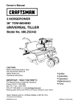
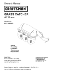
Owner's Manual
®
36" TOW-BEHIND
U IVERSAL TILLE
DO NOT RETURN
TO STORE
For Missing Parts or Assembly
Questions Call 1-866-576-8388
Model No. 486.24003
IMPORTANT!
The engine is shipped without oil. Oil must be added before starting
the engine. See Engine Maintenance on page 9 of this manual for instructions.
CAUTION:
,,
,,
,,
,,
,,
Before using this product, read
this manual and follow all Safety
Rules and Operating Instructions.
Sears, Roebuck
and Co., Hoffman
Estates,
Safety
Assembly
Operation
Maintenance
Parts
IL 60179 U.S.A.
www.sears.com/craftsman
PRINTED IN U.S.A.
FORM NO. 42488 (11/16/12)
WARRANTY ....................................................................
SAFETY RULES .............................................................
ASSEMBLY .....................................................................
OPERATION ................................................................
MAINTENANCE ...........................................................
CRAFTSMAN
2
3
4
5-7
8-9
SERVICE AND ADJUSTMENT ................................ 10-11
STORAGE .....................................................................
11
TROUBLESHOOTING ..................................................
12
REPAIR PARTS ........................................................
13-15
PARTS ORDERING/SERVICE ........................ Rear Cover
FULL WARRANTY
FOR ONE YEAR from the date of purchase, this product is warranted against defects in material or workmanship, A
defective product will receive free in-home repair or replacement if repair is unavailable,
WARRANTY SERVICE
For warranty coverage details to obtain free repair or replacement, call 1-800-659-5917 or visit the web site: www.
craftsman.corn
All of the above warranty coverage is void if this riding equipment is ever used while providing commercial services or if
rented to another person.
This warranty covers ONLY defects in material and workmanship. Warranty coverage does NOT include:
Expendable parts that can wear out from normal use within the warranty period, including but not limited to spark
plugs, air cleaners, belts, and oil filters.
Standard maintenance servicing, oil changes, or tune-ups.
Tire replacement or repair caused by punctures from outside objects, such as nails, thorns, stumps, or glass.
Tire or wheel replacement or repair resulting from normal wear, accident, or improper operation or maintenance.
Repairs necessary because of operator abuse, including but not limited to damage caused impacting objects that
bend the frame, axle assembly or crankshaft, or over-speeding the engine.
Repairs necessary because of operator negligence, including but not limited to, electrical and mechanical damage
caused by improper storage, failure to use the proper grade and amount of engine oil, failure to keep the product clear of
flammable debris, or failure to maintain the equipment according to the instructionscontained in the operator's manual.
Engine (fuel system) cleaning or repairs caused by fuel determined to be contaminated or oxidized (stale). In general,
fuel should be used within 30 days of its purchase date.
Normal deterioration and wear of the exterior finishes, or product label replacement.
This warranty gives you specific legal rights, and you may also have other rights which vary from state to state.
Sears Brands Management Corporation, Hoffman Estates, IL 60179
Record serial number and date of purchase in space
provided below.
MODEL NUMBER: 486.24003
SERIAL NUMBER:
DATE OF PURCHASE:
The model and serial number will be found on the
model plate attached to the right hand chassis.
You should record both serial number and date of
purchase and keep in a safe place for future reference.
PRODUCT SPECIFICATIONS
GASOLINETYPE
OIL (20 oz. Capacity):
Regular Unleaded
Above 32 F: SAE 20
Below 32 F: SAE 5W30
SPARK
TILLING
TILLING
TILLING
Gap: .030"
Approx. 2 MPH
36 in.
230 RPM
PLUG
GROUND SPEED:
WIDTH:
TINE SPEED:
DANGER:Thiscuttingmachineis capableofamputating
handsandfeet,andthrowingobjects.Failureto
observethefollowingsafetyinstructions
couldresultin seriousinjuryor death.
iMPORTANT
Look for this symbol to point out important
safety precautions. It means -- Attention!
Become Alert! Your safety is involved.
•
•
TRAINING
•
•
•
•
Read opening and service instructions carefully. Be
thoroughly familiar with the controls and the proper
use of the equipment.
Never allow children to operate the machine. Do not
allow adults to operate the machine without proper
instruction.
Keep the area of operation clear of all bystanders,
particularly small children and pets.
•
•
•
•
making adjustments, except for those which must
be done with the engine running.
Never place hands or feet under or into rotating
parts or concealed areas. Keep hands and feet
clearly away from auger elements, belts, pulleys,
etc. while engine is running.
Wear substantial shoes and eye protection while
using tiller.
Never attempt to make a maintenance adjustment
while engine is running, except on the carburetor.
Never run the engine indoors.
Never operate machine without proper guards,
plates, or other safety protective devices in place.
Disengage the tine clutch lever and stop the tiller
and tractor engines before getting off the tractor.
Disengage the tine clutch lever and stop the tiller
engine before transporting tiller.
PREPARATION
MAINTENANCE
•
•
•
•
•
•
•
Check fuel and lubrication before starting the engine.
Do not fill the gasoline tank while the engine is
running or still hot.
Do not fill the gasoline tank indoors.
Wipe off any spilled gasoline before starting the
engine.
Inspect the area to be tilled. Remove glass, wire,
metal objects, large sticks, and stones. Avoid
underground pipes and wiring.
Have a complete working knowledge of your tractor
and know how to handle your tractor with a tiller or
other attachment attached.
OPERATION
•
•
•
•
•
•
•
Give complete and undivided attention to the job at
hand. Operate the tiller in daylight or good artificial
light.
Always proceed slowly and carefully while operating
tiller.
Personal injury may result from contact with the
augers or debris thrown by this machine. Always stay
a safe distance away from the augers.
Shut off engine before leaving tiller unattended.
Check for loose fasteners or parts before each use.
Never store tiller inside a building while gasoline is
in the tank. Allow engine to cool before storing in an
enclosure.
Stop engine and disconnect spark plug lead wire
before cleaning augers, removing obstacles, or
•
•
•
AND STORAGE
Follow maintenance
instructions
as outlined in this
manual and the engine owner's manual.
Disconnect spark plug wire before making a
maintenance adjustment or repair.
Store gasoline in UL-approved non-spill containers.
Only use manufacturer replacement parts.
WARNING: This unit is equipped with an
internal combustion engine and should not
be used on or near any unimproved forestcovered or grass-covered land unless the engine's
exhaust system is equipped with a spark attester
meeting applicable local or state laws (if any). If a
spark attester is used, it should be maintained in
effective working order by the operator.
In the state of California, the above law is required by
law (Section 4442 of the California Public Resources
Code). Other states may have similar laws. Federal
laws apply on Federal lands. A spark attester for the
muffler is available through your nearest Sears
Authorized Service Center.
IMPORTANT! Add oil before starting engine. See Engine
Maintenance on page 9.
REMOVE
•
UNiT FROM CARTON
Cut all four corners of the carton from top to bottom
and lay panels flat. (See Figure 1)
Remove the lag screw that holds the floating hitch to
the packing skid.
Remove wooden top and side supports.
Remove four hex bolts, hex nuts, and flat washers
from the hold down brackets at the rear of the carton.
Remove and save the two flat washers and cotter
pins from the rear axle. Reuse when attaching gauge
wheels.
Discard all other packing hardware.
LAG SCREW
WOOD TOP
SUPPORTS
iNSTALL TILLER
TINE ASSEMBLIES
Attach floating hitch to tractor draw bar (Refer to
OPERATING iNSTRUCTiONS on page 6.)
Remove the pre-assembled 3/8" x 2" hex bolt and
3/8" nylock nut from the left hand tine assembly. Slide
the tine assembly onto the transmission axle on the
left side of the tiller and secure with the hex bolt and
nylock nut. (See Figure 3.) Repeat for opposite side.
3/8" NYLOCK
NUT
HOLD DOWN
BRACKET
EDGE
3/8" x 2"
HEX BOLT
AXLE
FIGURE
iNSTALL (WHEEL)
L
WOOD SIDE
SUPPORTS
"_-_
PACKING
SKID
FIGURE
iNSTALL TILLER
HEX BOLT
HEX NUT
FLAT WASHER
1
3
WEIGHTS
TO TILLER
NOTE: Weights are not furnished with the tiller. Wheel
weights may be purchased to mount to the tiller if extra
weight is required. (Refer to the OPERATION section of
this manual.)
Remove the four hex bolts and nuts located
approximately 3-1/2" from the front edge of the tine
shields. See Figure 4.
Secure (wheel) weights to tine shield using bolts and
nuts furnished with the weights. See Figure 4.
GAUGE WHEELS
Assemble gauge wheels onto rear axle with the
extended end of the hub facing inward. Secure with
the flat washers and cotter pins that were removed
from the axle during unpacking. (See Figure 2.)
WHEEL
LONG_
__
/
WEIGHT
/
TINE
SHIELD
REAR AXLE
COTTER PIN
NUTS
GAGE WHEELS
FLAT WASHER
FIGURE
2
FIGURE
4
RIGHT HAND (RH) AND LEFT HAND
DETERMINED
FROM THE DRIVERS
WHILE SEATED ON THE TRACTOR.
(LH) ARE
POSiTiON
REMOVE THE MOWER DECK FROM THETRACTOR
BEFORE USING THE TILLER. REFER TO YOUR
TRACTOR OWNER'S MANUAL.
KNOW YOU R TILLER
Compare the illustration below with your tiller to familiarize yourself with the location of various controls and adjustments.
CHOKE
CONTROL
TINE
CLUTCH
LEVER
FUEL
SHUT
OFF
LIFT HANDLE
FLOATING HITCH
\
THROTTLE
DEPTH STAKE
PULL START
FIGURE
SAFETY SWITCH - prevents engine from starting while
tine clutch lever is engaged
5
RECOIL START HANDLE - used to start the engine
THROTTLE CONTROL - controls engine speed
LiFT HANDLE - selects tilling or transport position by
moving gage wheels
FUEL SHUT OFF - shuts of fuel to engine
TINE CLUTCH LEVER - starts and stops tine rotation
CHOKE CONTROL - used when starting a cold engine
FLOATING HITCH - telescoping hitch limits shock loads
to tractor
DEPTH STAKE - controls tilling/cultivating depth
WARNING:
Flying debris can cause
starting and while operating tiller.
eye injury. Always
HOW TO USE YOUR TILLER
BEFORE
STARTING
YOUR TILLER
FILL
THE ENGINE WITH OIL! Your tiller engine is shipped
without oil or gasoline. Add oil as instructed in ENGINE
MAINTENANCE on page 9 of this manual. Add gas as
instructed in the engine manual.
WARNING: Never fill fuel tank indoors, with
the engine running, or while the engine is hot.
Do not smoke while filling tank.
STOPPING YOUR TILLER
•
wear eye protection
before
Repeat instructions in two preceding paragraphs until
engine starts. After engine starts, move choke control
gradually to RUN position.
Allow engine to warm up for a few minutes before
engaging tines.
ATTACHING TILLER TO TRACTOR
(See Figure 6)
Rear wheel weights and tire chains can be used on
tractor if additional traction is required for tilling.
Place tiller on level ground and back tractor up to it.
Attach hitch bracket extension to floating hitch of tiller
using a hitch pin and hair cotter pin.
•
Fasten hitch bracket extension to tractor drawbar with
a 1/2-13 x 1-1/4" hex bolt and 1/2" nylock nut.
TINES
•
Raise tiller to transport position.
Pull forward on tine clutch lever.
ENGINE (Refer to separate engine manual.)
•
Move throttle control to "STOP" position.
Turn shut off to "OFF" position.
Never use choke to stop engine.
HITCH BRACKET EXTENSION CAN BE ATTACHED
AS SHOWN iN FIGURE 6 OR TURNED UPSIDE
DOWN FOR TRACTORS WiTH LOWER DRAWBARS.
I
STARTING YOUR TILLER
(Refer to separate engine manual.)
CAUTION:
are hot!
III
HEX BOLT,
li2-13 X 1-1/4"
HITCH
TRACTOR
DRAWBAR
The muffler and adjacent areas
HITCH
1/2" NYLOCK
Check oil and gas in tiller engine.
Attach spark plug wire to spark plug.
Pull forward on tine clutch lever to disengage tines.
A safety switch prevents engine from starting while
tines are engaged.
Turn shut off to "ON" position.
Move choke lever on engine to CHOKE position. (A
warm engine may not require choking.)
Move throttle control lever on engine to FAST
position.
Grasp starter handle and pull rope out slowly until
engine reaches start of compression cycle (rope will
pull slightly harder at this point). Let the rope rewind
slowly.
Keep a firm grip on starter handle and pull rope with
a rapid, continuous, full arm stroke. Let rope rewind
slowly. Do not let starter handle snap back against
starter.
NUT
_
/
HAIR COTTER PIN
FIGURE
BREAKING
6
iN YOUR TILLER
Break-in your belts, pulleys, and the control before you
actually begin tilling.
Start engine with tiller attached to tractor in transport
position. Engage tine clutch lever to start tine rotation.
Allow tines to rotate for five minutes.
Check tine operation and adjust if necessary. See
TINE OPERATION CHECK in the SERVICE AND
ADJUSTMENTS section of this manual.
TRANSPORTING
YOUR TILLER
Extremely hard and dry soil will need to be cross
tilled at a shallow depth first, then tilled in the
direction of planting rows on the second pass at the
final depth.
Till in a pattern similar to that shown in Figure 7.
Make the first pass, skip a space equal to the width
of the tiller and make the return pass, then till the
skipped area. Tilling in this pattern will enable you to
maintain better control, if the passes are made sideby-side, the tractor and tiller will pull toward the tilled
(soft) side.
Check ground moisture. The ground is too wet if you
can make it into a ball with your hand. Tilling soil
when it is too wet will cause lumps which are difficult
to work up.
in soil that was tilled the year before, select the tilling
depth at which the tiller engine runs comfortable and
does not stall or pull down. Lower depth for additional
passes if great depth is desired.
Whenever working multiple passes, go perpendicular
to the previous tilling direction.
in cases where the soil is too hard to get proper
penetration or if tiling action causes tiller to hop or
bounce, it will be necessary to purchase a set of tiller
(wheel) weights.
AROUND THE YARD
•
Pull forward on lift handle until it locks in the transport
(up) position.
AROUND TOWN
Disconnect spark plug wire.
Drain fuel tank.
Transport in upright position to prevent oil leakage.
TO ADJUST DEPTH STAKE
•
The top depth stake hole selects a till depth of 1"
with each lower hole increasing till depth by 1" to a
maximum of 5".
•
To change till depth, remove the hair cotter pin from
the clevis pin which is connecting the depth stake to
the stake support bracket.
Grasp the top of the depth stake, remove the clevis
pin and reposition the depth stake. Insert clevis pin
and hair cotter pin.
•
iMPORTANT: THE DEPTH STAKE SHOULD NEVER BE
REMOVED FROM THE TILLER. IT IS DESIGNED TO
PROTECT THE TRACTOR TRANS AXLE FROM THE
THRUSTING ACTION OF THE TILLER.
CULTiVATiNG
TiLLiNG
Tilling should be done with the tiller engine full
throttle. If tiller engine seems to be overloaded or
stalls out, lower gauge wheels for shallower tilling.
Operate tiller engine at full throttle and operate tractor
in slowest forward speed with tractor engine at idle
speed or just above idle.
Soil conditions will determine how deep tiller can
penetrate on the first pass. In extremely hard ground,
several passes may be necessary to till to a depth of
6 inches. While in soft ground, tiller may penetrate to
a depth of 6 inches in the first pass.
TiLLiNG
A minimum of two (2) inches of soil penetration is
required for cultivating.
Set depth stake so the tiller penetrates soil to a depth
of 2 to 3 inches.
Run the tiller engine at full throttle except when
cultivating small plants. A slower engine speed
is necessary to prevent burying small plants.
See Figure 8.
HINTS
iMPORTANT OPERATING HINTS
NOTE: The following are general guidelines for tilling, but
may vary depending upon soil conditions.
in virgin soil, the tiller should be started in shallowest
depth position and lowered one position at a time
after each pass in each direction.
i=
----
-5
m
u
FIGURE
7
FIGURE
8
GENERAL
RECOMMENDATIONS
Once a year you should replace the spark plug, clean
or replace the air filter, and check tines and belts for
wear. A new spark plug and clean air filter ensure
proper air-fuel mixture and help your engine run
better and last longer.
The warranty on this tiller does not cover items that
have been subjected to operator abuse or negligence.
To receive full value from the warranty, operator must
maintain unit as instructed in this manual.
BEFORE
Some adjustments will need to be made periodically to
properly maintain your unit.
All adjustments in the SERVICES AND ADJUSTMENTS
section of this manual should be checked at least once
each season.
•
EACH USE
Check engine oil level.
Check tine operation.
Check for loose fasteners
LUBRICATION
Keep unit well lubricated. See LUBRICATION
CHART.
Refer to the engine manual for instructions on engine maintenance.
MAINTENANCE
SCHEDULE
Fill in dates as you
complete regular service.
Chgck 9ngin 9 o!! !9v9!
_
_o
._
. Q, _._
/,_/4,_
/__/___/_.-X
/
/__- / :_<_"/!o',_/._,_Y
_b_,e-"/_._-/
/ _
/ ,'V'_/ _o-_/ _-_j _J _
X
_
.
_ervlce Dates
Change engine oil
Service air cleaner pre-cleaner
Service air cleaner cartridge
Replace spark plug
Clean cooling system
Check valve clearance
Check for loose fasteners
Lubricate tiller
X**
X
X**
X
X
X
*Change oil every 25 hours when operating the engine under heavy load or in high temperatures.
**Clean more often under dusty conditions or when airborne debris is present. Replace air cleaner parts, if very dirty.
(_)
REFER TO SEPARATE ENGINE OPERATING &
MAINTENANCE INSTRUCTIONS
(_
REFER TO MAINTENANCE, TILLER
LUBRICATION SECTION
(_)
GENERAL PURPOSE GREASE
(_ ENGINE_
IMPORTANT: DO NOT OIL OR GREASE PIVOT POINTS.
VISCOUS LUBRICANTS WILL ATTRACT DUST AND
DIRT THAT CAN CAUSE WEAR ON PIVOT POINTS. IF
YOU FEEL THEY MUST BE LUBRICATED, USE ONLY A
DRY POWDERED GRAPHITE TYPE LUBRICANT.
TINE SHAFT
@TILLER
@AXLE
SHAFT_
FIGURE
9
TRANSMiSSiON
LUBRiCATiON
Check the transmission oil level after first 5 hours of
operation. Remove oil fill plug (figure 10). Oil level must
be even with the plug hole (with tiller level). Add oil if
necessary. Use SAE 30 non-detergent motor oil. Replace
oil fill plug.
MUFFLER
Do not operate tiller without muffler. Do not tamper with
exhaust system. Damaged mufflers or spark attesters
could create a fire hazard. Inspect periodically and
replace if necessary. If your engine is equipped with a
spark attester screen assembly, remove every 50 hours
for cleaning and inspection. Replace if damaged.
Check the transmission oil level after each 10 hours of
operation.
NOTE: It is not necessary to change the oil in this tiller
transmission. If for any reason it must be changed, oil
capacity is 22 oz.
BEARING
LUBRICATION
Grease the tine shaft bearings every 8-10 hours. Use a
grease gun to apply about 10 pumps of General Purpose
grease in the grease fittings. Wipe off excess grease
that is forced out of the bearings. Perform this lubricating
)rocedure more often in dry and dusty environments.
OIL FILL PLUG
ENGINE MAINTENANCE
WARNING:
Always stop engine and
disconnect spark plug wire before cleaning,
lubricating, or before performing any repairs
or maintenance.
Check oil level before each use and every 8 hours.
Maintain oil at level shown in figure 11 below.
Service air cleaner every 25 hours under normal
conditions. Clean every few hours under extremely
dusty conditions. Poor engine performance and
flooding usually indicates that the air cleaner should
be serviced. Refer to separate engine manual to
service the air cleaner.
Spark plug replacement is recommended every 100
hours or yearly. Check the engine manual for correct
plug type and gap specifications.
ENGINE
MUST BE LEVEL
GREASE FITTING
REMOVE OIL CAP
FIGURE
10
CLEANING
•
CAP
AFTER FILLED
Clean engine as instructed in the engine manual.
Clean wheels, finish, etc. of all foreign matter.
Keep finished surfaces and wheels free of all
gasoline, oil, etc.
Protect painted surfaces with automotive type wax.
OiL LEVEL
Do not use a garden hose to clean your unit unless the
muffler, air filter, and carburetor are covered to keep water
out. Water in the engine will result in shorter engine life.
FIGURE
11
WARNING: Shut off (disengage) the Tine
Clutch Lever, the Tiller Engine, and the
Tractor Engine before making any repairs.
BELT GUIDE
TRANSMISSION
PULLEY
CLUTCHING
PULLEY
TO REPLACE V-BELT
ENGINE
PULLEY
Replace V-belt if it has been damaged considerably from
slipping under heavy loads or if it show cracks or frayed
edges. Refer to figures 12 and 13.
IMPORTANT: Do not move or remove the belt guide.
If the position of the belt guide is accidentally altered,
return it to the correct setting (6-1/2" above the tine shield
support plate).
•
TINE SHIELD
SUPPORT
PLATE
Remove the screw from the top of the belt guard.
Remove the hex nut from the rear of the guard.
Remove the belt guard to allow access to drive belt.
Disengage tine clutch lever and remove belt.
Reverse above procedures for installation of new belt.
BELT ROUTING
FIGURE
BELT GUIDE
DRIVE BELT
SCREW
"_-_
BELT GUARD
TINE SHIELD SUPPORT
FIGURE
10
PLATE
12
13
SPARE TINE DRIVE BOLTS
WARNING:Shutoff(disengage)
theTine
ClutchLever,theTillerEngine,andthe
TractorEnginebeforemakinganyrepairs.
•
TINE CARE
For best results -- tine blades should be kept
reasonably sharp. The tine blade can be sharpened
on a grinding wheel. Do not attempt to sharpen tines
while they are mounted to tiller.
Prepare your tiller for storage at the end of the season or
if the unit will not be used for 30 days or more.
The tiller drive components are protected from
damage by (shearable) grade 5 hex bolts in the
tine assemblies. The hex bolts drive the tines and
hold them in the proper location. Should the tine
assemblies strike or pick up a large hidden object
or become jammed, the hex bolts will break and the
drive components will not be damaged.
Two extra tine hex bolts and nuts are included with
the tiller. They are located in the tiller stake support
bracket on the rear of the tiller.
The tine hex bolts are designed to be loose fit. Do not
attempt to use a bolt or pin that is larger or harder
than the original grade 5 hex bolts.
Touch up all rusted or chipped paint surfaces; sand
lightly before painting.
Store tiller indoors and cover it to protect from dust
and dirt.
Cover tiller with a suitable protective cover that does
not retain moisture. Do not use plastic. Plastic allows
condensation to form and will cause your unit to rust.
CAUTION: Never store the tiller with
gasoline in the tank inside a building, where
fumes may reach an open flame or spark.
Allow the engine to cool before storing in any
enclosure.
ENGINE
Follow instructions in the Engine Manual.
WARNING: Never cover tiller while engine
and exhaust areas are still warm.
TILLER
Clean entire tiller (See CLEANING in the
MAINTENANCE section of the manual).
Inspect belts and replace if necessary (See belt
replacement instructions in the SERVICE AND
ADJUSTMENTS section of this manual.
Lubricate as instructed in the MAINTENANCE
section of this manual.
Check that all nuts, bolts, and screws are securely
fastened. Inspect moving parts for damage,
breakage, and wear. Replace if necessary.
11
Follow the instructions in the Engine Manual when performing
any work on the engine.
PROBLEM
Probable
Cause
_
Possible
Remedy
WILL NOT START OR HARD TO START
No gasoline in fuel tank
Fill tank with gasoline
Choke not set properly
Place choke control in choke position
Place throttle control in fast position
Throttle control not set properly
Choked improperly, flooded engine
Move choke control to run position, place throttle control in fast
position and pull starter several times to clear out gas
Dirty air cleaner
Remove to inspect, replace if dirty
Loose spark plug wire
Make sure spark plug wire is seated properly on spark plug
Spark plug dirty or improper gap
Replace spark plug and adjust gap
Water in gasoline or old fuel
Drain fuel tank and carburetor, use fresh fuel and replace spark plug
Remove and clean
Clogged fuel tank
ENGINE MISSES OR LACKS POWER
Engine overloaded
Set depth stake and wheels for shallower tilling
Partially plugged air cleaner
Remove and clean or replace
Clean air screen
Dirty air screen
Spark plug dirty, improper gap or wrong type
Replace spark plug and adjust gap
Drain and refill tank and carburetor
Oil in gasoline
Clogged fuel tank
Remove and clean
Poor compression
Major engine overhaul
ENGINE OVERHEATS
Low oil level or dirty oil
========-_Add or change oil
Clean air screen
Dirty air screen
Dirty engine
Clean cylinder fins air screen and muffler area
Remove and clean muffler
Partially plugged muffler
EXCESSIVE
BOUNCE
Wheels and depth stake incorrectly adjusted
HANDLING
Adjust wheels and depth stake
Ground too dry and hard
Moisten ground or wait for more favorable soil conditions
SOIL BALLS
Ground too wet
AND DIFFICULT
_
UP OR CLUMPS
Wait for more favorable soil conditions
ENGINE RUNS WELL BUTTILLER
Tine control not engaged
_
Engage tine control
V-belt off of pulleys
_
Check v-belt
WON'T MOVE
ENGINE RUNS WELL BUT LABORS WHEN TILLING
Tilling too deep
_
Adjust depth stake
Throttle control not properly adjusted
_
Check throttle control setting
12
REPAIR PARTS FOR MODEL 486.24003
36" TOW=BEHIND
15
UNIVERSAL
_10
TILLER
9
16
\
21
1
\
\
21
2
13
14
4
\
25
\
\
12
5
18
\
24
\
17
\
7
22
6
5
3
1
REF.
1
2
3
4
5
6
7
8
9
10
11
12
13
PART NO. QTY.
DESCRiPTiON
HA20125
2
Felt Washer
26707
2
Cap
49983
8
Flanged Lock Nut, 5/16-18
67559
2
Flange and Bearing Assembly
HA20122
2
Flange Gasket
66721
1
Drive Housing (LH)
(includes items 9 & 10)
HA20136
1
Drive Gasket
HA20130
1
Oil Plug
HA20138
3
Bearing Cap
HA20137
4
Roller Bearing
47598
19 Washer Faced Lock Nut, 1/4-20
66269
1
Tine Shaft and Sprocket Assembly
42088
1
Roller Chain (Short)
REF.
15
16
17
18
PART NO. QTY.
1
66270
1
66271
1
HA20145
1
42087
1
66720
19
20
HA20134
40560
21
22
23
24
25
HA20129
66225
66224
43054
HA21362
14
13
1
19
4
1
1
4
4
DESCRiPTiON
Idler Shaft Assembly
i Input Shaft Assembly
Seal
Roller Chain (Long)
Drive Housing (RH)
j(includes items 9 & 10)
Belt Guard and Idler Bracket
Washer Head Bolt, 1/4-20 x 5/8"
Thrust Washer
Tine
Tine
Bolt,
Nut,
Assembly (LH)
Assembly (RH)
3/8-16 x 2" (2 spare)
Hex Nylock 3/8-16 (2 spare)
75
76
rn
24
13
m
77
-t
2
78
0
5
27
/
\
10
32
0
47
84
m
y
67
44
73
\
/
\
36
14
69
o
o
62
\
\
\\
16
\
\ 66
54
28
0
') 54
\
m
\
80
60
z
23
64
rn
23
80
49
r-
.-!
rrm
REPAIR PARTS FOR MODEL 486.24003
36" TOW=BEHIND
REF.
PART NO.
QTY.
DESCRiPTiON
REF.
PART NO.
QTY.
1
2
3
4
42463
48346
43085
HA115321
1
1
4
2
Engine (50 State)
Guide - Belt
Bolt, 5/16-18 x 1-1/2" Hex Head
Set Screw, 5/16-18 x 5/16"
47
48
49
50
47600
HA5236
43062
HA20918
1
1
1
2
5
6
7
8
9
10
11
12
13
14
15
16
17
18
HAl1154
40906
48733
HA124934
HA19860
64282
43063
43064
64343
48840
43081
HA20135
HA20184
HA20178
1
1
1
1
1
1
5
1
1
3
2
2
1
1
Key, Square 1/4" x 2"
Pulley
Nut, 1/2-12 Nylock Jam
Nut, 1/2-12 Hex Jam
Spring, Depth Extension
Hitch Bracket Assembly
Bolt, 5/16-18 x 1" Hex Head
Locknut, 5/16-18 Hex
Lift Handle Assembly
Screw, Self-Tapping 1/4" x 1/2"
Washer, 5/16" Std. Wrt.
Ring, Retainer
Pulley, input
Bolt - Shoulder
51
52
53
54
55
56
57
58
59
60
61
62
63
64
R74780828
HA20670
26568
HA20725
HA3433
HA20690
HA20932
HA20940
43001
47810
41576
R74760884
44326
24849
1
1
1
2
2
1
2
1
8
11
5
1
2
1
19
20
47189
40843
2
1
Nut, Hex Nylock 1/4-20
Clutch Rod
65
66
HA14306
HA20691
1
1
21
22
HA23199
24847
1
1
Switch, Safety interlock
Lever, Clutch
67
68
712-3083
HA20938
4
2
23
24
25
26
27
28
HA21362
HA20170
49152
HA20134
47630
43661
15
1
2
1
4
5
Nut, Hex Nylock 3/8-16
Grip, Handle
Rivet, Pop
Belt Guide & idler Mounting Bracket
Screw, 5/16-18 x 3/4" Self Tap
Bolt, 1/4-20 x 1" Hex Head
69
70
71
72
73
74
HA20942
HA5713
HA15200
712-0261
HA7974
48278
1
1
2
1
2
1
29
30
31
32
33
34
35
HA20185
24863
67558
24843
HA20186
24844
26124
1
1
1
1
1
1
1
Key, Woodruff No. 61
Cover, Drive
Transmission - Complete
Chassis, Left
Spring, Extension
Chassis, Right
Bracket, idler
75
76
77
78
79
80
81
43010
HA20688
HA19649
R19171616
40699
HA456151
HA20481
6
1
1
1
1
4
2
36
37
38
39
40
41
42
43
44
HA11496
HA20187
47598
66397
43182
26559
714-0117
26366
43910
1
1
8
1
1
1
1
1
2
Pulley, idler
V-Belt
Washer Faced Lock Nut, 1/4-20
Module
Hex Bolt, 5/16-18 x 3/4"
Hitch Bracket Extension
Pin - Hair Cotter 5/32"
Fender Plate
#10 Washer
82
83
84
85
86
87
88
89
90
43070
43012
43178
HA20692
R19212113
43346
47171
40710
HA3090
16
4
2
1
1
1
1
1
1
45
46
43351
40711
1
1
Bolt, Hex 1/2-13 x 1-1/4"
Nylock Nut, 8-32
42488
1
15
UNIVERSAL
TILLER
DESCRiPTiON
Bolt, Hex 5/16-24 x 1"
Pin, Hitch
Bolt, 3/8-16 x 1-1/2" Hex Head
Wheel
Bolt, 1/2-13 x 1-3/4" Hex Head
Pivot Axle Assembly
Anchor
Strap Frame Extension
Pin, Clevis
Stake, Drag
Bracket -- Wheel Weight Support
Decal, Danger
Hex Bolt, 3/8-16 x 1"
Nut, Hex 5/16-18 Nylock
Bolt - 3/8-16 x 1-3/4" Hex Head
Bolt, 1/2-13 x 5-1/2" Hex Head
Bolt, 5/16-18 x 1" Carriage
Belt Guard (incl. #69)
Washer
Strap-Frame Extension Brace
Nut, 1/2-13 Nylock
Decal, Danger
Decal
Spacer
Washer
Nut, Hex 5/18-11 Nylock
Spacer
Bolt, Hex 5/8-11 x 7-1/2"
Pin - 1/8"x 1-1/4" Cotter
Rod - Lift
Anchor - Adjustment
Washer, .531 x 1 x .059"
Plastic Tie w/#8 Screw Hole
Washer, 13/16" x 1-1/2" x .134" Flat
Pin - Hair Cotter
Washer, 3/8"
Hex Bolt, 1/4-20 x 3/4"
Nut, 1/4-20 Hex
Hitch Tube Assem. (incl. with #10)
Washer, 5/8"
Slot Truss Bolt, 10-32 x 5/8"
Nylock Nut, 10-32
Screw, 8-32 x .625
Pin - Hair Cotter
Owner's Manual
Riding Equipment
questions or problems?
Satisfaction with your purchase
is our number one concern!
To troubleshoot problems,
get answers to questions, order parts,
or schedule repair service for your
Riding Equipment, call the number below.
Para respuestas a preguntas o problemas,
y ordenar piezas o pedir servicio para la
reparacibn de su equipo, Ilame el n_mero abajo.
1-800-659-5917
Craftsman Help Line
www.craftsman.com
® Registered Trademark /
® Marca
Registrada
TM
Trademark of KCD IP, LLC in the United States, or Sears Brands, LLC in other countries
/ TM Marca
de Fabrica
de KCD
IP, LLC en Estados
Unidos,
o Sears
Brands,
LLC in otros paises