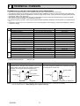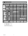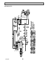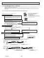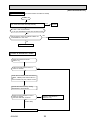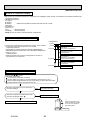
1
SPLIT-TYPE, HEAT PUMP AIR CONDITIONERS
October 2012
No.OCH530
HFC
utilized
TECHNICAL & SERVICE MANUAL
R410A
R410A
Outdoor unit
[Model names]
SUZ-KA25VA3
SUZ-KA35VA3
SUZ-KA50VA3
SUZ-KA60VA3
SUZ-KA71VA3
NOTE:
• This service manual describes
technical data of the outdoor
units.
[Service Ref.]
SUZ-KA25VA3.TH
SUZ-KA35VA3.TH
SUZ-KA50VA3.TH
SUZ-KA60VA3.TH
SUZ-KA71VA3.TH
CONTENTS
Indication of
model name
SUZ-KA25VA3.TH
SUZ-KA35VA3.TH
1. COMBINATION OF INDOOR AND OUTDOOR UNITS.......2
2. TECHNICAL CHANGES ....................................3
3. PART NAMES AND FUNCTIONS......................6
4. SPECIFICATION................................................. 7
5. NOISE CRITERIA CURVES............................... 9
6. OUTLINES AND DIMENSIONS........................10
7. WIRING DIAGRAM...........................................12
8. REFRIGERANT SYSTEM DIAGRAM.............. 15
9. ACTUATOR CONTROL....................................18
10. SERVICE FUNCTIONS.....................................19
11. TROUBLESHOOTING...................................... 19
12. DISASSEMBLY INSTRUCTIONS..................... 49
PARTS CATALOG (OCB530)
1
COMBINATION OF INDOOR AND OUTDOOR UNITS
INDOOR UNIT SERVICE MANUAL
Outdoor unit
Heat pump type
Indoor unit
SUZService Ref.
Service
KA25VA3.TH KA35VA3.TH KA50VA3.TH KA60VA3.TH KA71VA3.TH
Manual No.
—
SLZ-KA25VA(L).TH
—
SLZ-KA35VA(L).TH
SLZ-KA50VA(L).TH
Heat pump without electric heater
SLZ-KA25VAL2.TH
OC320
—
—
SLZ-KA50VALR3.TH
—
—
OCH493
SLZ-KA50VAQR2.TH
—
HWE0711
SEZ-KD50VA(L)R2.TH
BWE102050
SEZ-KD60VA(L)R2.TH
SEZ-KD71VA(L)R2.TH
—
—
HWE1008
SEZ-KD50VAQR2.TH
BWE102040
SEZ-KD60VAQR2.TH
SEZ-KD71VAQR2.TH
—
—
—
—
—
—
—
—
—
—
—
—
—
—
—
—
—
—
—
—
—
—
—
—
—
—
—
—
—
—
—
—
—
—
—
—
—
—
—
—
—
—
—
—
—
—
SEZ-KD25VAQR2.TH
SEZ-KD35VAQR2.TH
—
—
—
SEZ-KD25VA(L)R2.TH
SEZ-KD35VA(L)R2.TH
—
—
SLZ-KA25VAQ2.TH
SLZ-KA35VAQR2.TH
—
—
—
SLZ-KA35VALR3.TH
—
—
—
—
—
—
—
—
—
—
—
—
—
(NOTE) Please refer to the service manual of indoor unit or the technical data book for the combination data.
OCH530
2
2
TECHNICAL CHANGES
INFORMATION FOR THE AIR CONDITIONER WITH R410A REFRIGERANT
oil
Refrigerant
Refrigerant
• This room air conditioner adopts an HFC refrigerant (R410A) which never destroys the ozone layer.
• Pay particular attention to the following points, though the basic installation procedure is same as that for R22 conditioners.
1 As R410A has working pressure approximate 1.6 times as high as that of R22, some special tools and piping parts/materials
are required. Refer to the table below.
2 Take sufficient care not to allow water and other contaminations to enter the R410A refrigerant during storage and installation, since it is more susceptible to contaminations than R22.
3 For refrigerant piping, use clean, pressure-proof parts/materials specifically designed for R410A. (Refer to 2. Refrigerant piping.)
4 Composition change may occur in R410A since it is a mixed refrigerant. When charging, charge liquid refrigerant to prevent
composition change.
Refrigerant
Composition (Ratio)
Refrigerant handling
Chlorine
Safety group (ASHRAE)
Molecular weight
Boiling point (°C)
Steam pressure [25°C](Mpa)
Saturated steam density [25°C](Kg/*)
Combustibility
ODP *1
GWP *2
Refrigerant charge method
Additional charge on leakage
Kind
Color
Smell
*1: Ozone Depletion Potential
*2: Global Warming Potential
New refrigerant
R410A
HFC-32: HFC-125 (50%:50%)
Pseudo-azeotropic refrigerant
Not included
A1/A1
72.6
-51.4
1.557
64
Non combustible
0
1730
From liquid phase in cylinder
Possible
Incompatible oil
None
None
: based on CFC-11
: based on CO2
New Specification
Compressor
Previous refrigerant
R22
R22 (100%)
Single refrigerant
Included
A1
86.5
-40.8
0.94
44.4
Non combustible
0.055
1700
Gas phase
Possible
Compatible oil
Light yellow
None
Current Specification
The incompatible refrigerant oil easily separates from
Since refrigerant and refrigerant oil are compatible with
refrigerant and is in the upper layer inside the suction muffler. each other, refrigerant oil backs to the compressor through
Raising position of the oil back hole enables to back the
the lower position oil back hole.
refrigerant oil of the upper layer to flow back to the
compressor.
Suction muffler
Suction muffler
Compressor
Oil back hole
Compressor
Refrigerant oil
Refrigerant
Oil back hole
Refrigerant oil /Refrigerant
NOTE : The unit of pressure has been changed to MPa on the international system of units (SI unit system).
The conversion factor is: 1 (MPa [Gauge]) =10.2 (kgf/cm2 [Gauge])
OCH530
3
Conversion chart of refrigerant temperature and pressure
(MPa [Gauge])
4.0
Saturated liquid pressure
3.5
R410A
3.0
R22
2.5
2.0
NOTE: The unit of pressure has been changed to MPa on the
international system of units (SI unit system).
1.5
1.0
The conversion factor is: 1 (MPa [Gauge]) =10.2 (kgf/cm2 [Gauge])
0.5
0.0
-0.5
-30 -20 -10
0
10
20
30
40
50
60
()
1. Tools dedicated for the air conditioner with R410A refrigerant
The following tools are required for R410A refrigerant. Some R22 tools can be substituted for R410A tools.
The diameter of the service port on the stop valve in outdoor unit has been changed to prevent any other refrigerant being
charged into the unit. Cap size has been changed from 7/16 UNF with 20 threads to 1/2 UNF with 20 threads.
R410A tools
Description
Can R22 tools be used?
R410A has high pressures beyond the measurement range of existing
gauges. Port diameters have been changed to prevent any other refrigerant
from being charged into the unit.
Gauge manifold
No
Charge hose
No
Gas leak detector
No
Hose material and cap size have been changed to improve the pressure
resistance.
Dedicated for HFC refrigerant.
Yes
6.35 mm and 9.52 mm
No
12.7 mm and 15.88 mm
Flare tool
Yes
Clamp bar hole has been enlarged to reinforce the spring strength in the tool.
Flare gauge
Vacuum pump
adapter
Electronic scale for
refrigerant charging
New
Provided for flaring work (to be used with R22 flare tool).
Provided to prevent the back flow of oil. This adapter enables you to use
vacuum pumps.
It is difficult to measure R410A with a charging cylinder because the
refrigerant bubbles due to high pressure and high-speed vaporization
Torque wrench
New
New
No: Not substitutable for R410A
OCH530
Yes: Substitutable for R410A
4
2. Refrigerant piping
1 Specifications
Use the refrigerant pipes that meet the following specifications.
Outside diameter
mm
6.35
9.52
9.52
12.7
15.88
Pipe
For liquid
For gas
Wall thickness
mm
0.8
0.8
0.8
0.8
1.0
Insulation material
Heat resisting foam plastic
Specific gravity 0.045
Thickness 8 mm
• Use a copper pipe or a copper-alloy seamless pipe with a thickness of 0.8 mm. Never use any pipe with a thickness less
than 0.8mm, as the pressure resistance is insufficient.
2 Flaring work and flare nut
Flaring work for R410A pipe differs from that for R22 pipe.
For details of flaring work, refer to Installation manual “FLARING WORK”.
Dimension of flare nut (mm)
Pipe diameter (mm)
R410A
6.35
9.52
12.7
15.88
R22
17
22
24
27
17
22
26
29
3. Refrigerant oil
Apply the special refrigerant oil (accessories: packed with indoor unit) to the flare and the union seat surfaces.
4. Air purge
Do not discharge the refrigerant into the atmosphere.
Take care not to discharge refrigerant into the atmosphere during installation, reinstallation, or repairs to the refrigerant
circuit.
Use the vacuum pump for air purging for the purpose of environmental protection.
5. Additional charge
For additional charging, charge the refrigerant from liquid phase of the gas cylinder.
If the refrigerant is charged from the gas phase, composition change may occur in the refrigerant inside the cylinder and
the outdoor unit. In this case, ability of the refrigerating cycle decreases or normal operation can be impossible. However,
charging the liquid refrigerant all at once may cause the compressor to be locked. Thus, charge the refrigerant slowly.
Union
Stop valve
Indoor unit
Liquid pipe
Gas pipe
Refrigerant gas
cylinder
operating valve
Outdoor unit
Service port
Gauge manifold
valve (for R410A)
Charge hose (for R410A)
Refrigerant gas cylinder
for R410A with siphon
Refrigerant (liquid)
Electronic scale for refrigerant charging
OCH530
5
3
PART NAMES AND FUNCTIONS
SUZ-KA25VA3.TH
SUZ-KA35VA3.TH
Air inlet
(back and side)
Piping
Drain hose
Air outlet
Drain outlet
SUZ-KA50VA3.TH
SUZ-KA60VA3.TH
SUZ-KA71VA3.TH
Air inlet
(back and side)
Piping
Drain hose
Air outlet
Drain outlet
Model
Drain socket
OCH530
SUZ-KA·VA3.TH
1
6
4
SPECIFICATION
Outdoor model
SUZ-KA25VA3.TH SUZ-KA35VA3.TH SUZ-KA50VA3.TH SUZ-KA60VA3.TH SUZ-KA71VA3.TH
Power supply
Single phase 230V, 50Hz
Model
KNB073FKFMC
Output
W
Cooling
Compressor Current
*1
Heating
Refrigeration oil
(Model)
A
L
Dimensions W × H × D
mm
Weight
kg
Cooling
Sound level *1
6.62
8.02
3.24
4.09
5.75
6.37
8.13
0.31 (FV50S)
0.27 (FV50S)
Fan
speed
RC0J60-BD
RC0J60-BC
0.24
0.29
0.84
0.84
0.83
0.27
0.28
0.93
0.93
0.82
800 × 550 × 285
35
840 × 880 × 330
50
53
3,492
3,426
Med.
1,806
2,868
3,066
3,006
1,602
1,692
1,512
2,778
2,952
2,892
2,892
m³/h
30
1,170
1,038
2,106
Med.
1,806
1,770
2,778
2,952
Low
1,452
1,326
2,124
2,226
Cooling
47
49
52
55
48
50
52
55
740
810
840
950
Heating
dB(A)
Med.
740
810
Low
740
490
860
900
rpm
Med.
740
770
Low
600
610
Fan speed regulator
Refrigerant filling capacity
(R410A)
2,280
840
480
450
810
810
620
650
3
kg
0.80
1.15
NOTE : Test conditions are based on ISO 5151
Cooling : Indoor D.B. 27°C
W.B. 19°C
Outdoor D.B. 35°C
Heating : Indoor D.B. 20°C
Outdoor D.B. 7°C
W.B. 6°C
Refrigerant piping length (one way): 5 m
*1 Measured under rated operating frequency.
OCH530
0.4 (FV50S)
54
High
Heating
0.35 (FV50S)
2,868
High
Cooling
1,200
5.58
1,806
High
Heating
900
650
4.06
High
Low
Air flow
*1
Special remarks
A
SNB172FEKMT
550
RC0J50-FA
Current Cooling
*1
Heating
SNB130FGBMT
2.76
Model
Fan motor
KNB092FFAMC
7
1.45
1.55
1.90
Specifications and rating conditions of main electric parts
SUZ-KA25VA3.TH SUZ-KA35VA3.TH
SUZ-KA50VA3.TH SUZ-KA60VA3.TH
SUZ-KA71VA3.TH
Model
Item
(C61)
Smoothing
capacitor
Diode module
Fuse
—
—
620+ 420V
(C62, C63)
620+ 420V
620+ 420V
620+ 420V
—
—
(CB1, 2, 3)
—
—
—
560μF 450V
560μF 350V
15A 600V
15A 600V
25A 600V
—
—
(F61)
T20A L250V
T20A L250V
T20A L250V
—
—
(F62)
—
—
—
T20A L250V
T20A L250V
T3.15A L250V
T3.15A L250V
T3.15A L250V
—
—
15A 600V
15A 600V
20A 600V
—
—
—
—
8A 600V
8A 600V
8A 600V
5A 600V
5A 600V
(DB61)
(F701, F801, F901)
(IC700)
(IPM)
Inteligent power
module
(IC932)
Power factor
controller
(IC820)
(PFC)
Expansion valve
coil
(L61)
(L)
R.V. coil
—
—
20A 600V
20A 600V
20A 600V
—
—
DC12V
18mH
23mH
23mH
—
—
—
—
—
340μH 20A
340μH 20A
33Ω
(TB1, TB2)
—
—
—
3P
3P
(TB)
5P
5P
5P
—
—
(X63)
3A 250V
3A 250V
3A 250V
—
—
(X601)
—
—
—
3A 250V
3A 250V
(X602)
—
—
—
3A 250V
3A 250V
20A 250V
(21S4)
OCH530
—
20A 600V
20A 600V
(X64)
Relay
—
—
(PTC64, PTC65)
Terminal block
—
20A 600V
(LEV)
Reactor
Current-Limiting
PTC thermistoe
SUZ-KA25VA3.TH SUZKA35VA3.TH SUZ-KA50VA3.TH SUZ-KA60VA3.TH SUZ-KA71VA3.TH
AC220-240V
8
5
NOISE CRITERIA CURVES
SUZ-KA35VA3.TH
SUZ-KA25VA3.TH
OCTAVE BAND SOUND PRESSURE LEVEL, dB re 0.0002 MICRO BAR
High
Med.
SPL(dB(A))
COOLING
47
HEATING
48
FAN SPEED FUNCTION
LINE
High
Med.
OCTAVE BAND SOUND PRESSURE LEVEL, dB re 0.0002 MICRO BAR
FAN SPEED FUNCTION
90
80
70
NC-70
60
NC-60
50
NC-50
40
NC-40
30
NC-30
20
NC-20
NC-10
10
63
125
250
500
1000
2000
4000
8000
COOLING
52
HEATING
52
70
NC-70
60
NC-60
50
NC-50
40
NC-40
30
NC-30
20
10
63
125
80
NC-70
60
NC-60
50
NC-50
40
NC-40
30
NC-30
20
10
63
125
250
250
500
1000
2000
NC-20
4000
500
1000
2000
4000
8000
SPL(dB(A))
COOLING
55
HEATING
55
LINE
90
80
70
NC-70
60
NC-60
50
NC-50
40
NC-40
30
NC-30
20
NC-20
NC-10
10
63
125
BAND CENTER FREQUENCIES, Hz
250
500
1000
2000
4000
8000
BAND CENTER FREQUENCIES, Hz
Test conditions
Cooling: Dry-bulb temperature 35°C
Heating: Dry-bulb temperature 7°C
Wet-bulb temperature 6°C
OUTDOOR UNIT
1m
MICROPHONE
OCH530
8000
SUZ-KA71VA3.TH
FAN SPEED FUNCTION
LINE
90
NC-10
NC-20
NC-10
High
70
50
80
SUZ-KA60VA3.TH
OCTAVE BAND SOUND PRESSURE LEVEL, 0dB re 0.0002 MICRO BAR
OCTAVE BAND SOUND PRESSURE LEVEL, dB re 0.0002 MICRO BAR
High
HEATING
LINE
BAND CENTER FREQUENCIES, Hz
SUZ-KA50VA3.TH
SPL(dB(A))
49
90
BAND CENTER FREQUENCIES, Hz
FAN SPEED FUNCTION
SPL(dB(A))
COOLING
9
6
OUTLINES AND DIMENSIONS
SUZ-KA25VA3.TH
SUZ-KA35VA3.TH
Unit: mm
REQUIRED SPACE
Basically open 100mm or more
without any obstruction in front
and on both sides of the unit.
Bolt pitch for
installation
304~325
44
Air in
40
2-Oval holes 10×21
Open two sides of left,
right, or rear side.
Air out
22.3
ore
or m
mm
0
0
2
17.5
Service panel
23
Liquid refrigerant pipe joint
Refrigerant pipe (flared) :6.35
Handle
35
69
302.5
Gas refrigerant pipe joint
Refrigerant pipe (flared) :9.52
99.5
10
164.5
280
150
170.5
Service port
500 Bolt pitch for installation
800
OCH530
43
285
100
mm
or m
ore
Drain hole :42
550
344.5
400
Air in
10
re
r mo
mo
m
100
350
mm
or m
ore
SUZ-KA50VA3.TH
SUZ-KA60VA3.TH
SUZ-KA71VA3.TH
Unit: mm
Open as a rule
500mm or more if
the front and both
sides are open
REQUIRED SPACE
417.5
Drain hole
40
50
Bolt pitch for
installation
360
42
Air in
100
mm
100mm or more
200mm or more if
there are obstacles
to both sides
or m
ore
Air out
2-Oval holes 10 21
175
350
500
840
Open as a rule
500mm or more if the back,
both sides and top are open
81
109
mm
or m
ore
Service panel
Liquid refrigerant
pipe joint
Refrigerant pipe
(flared)
Ø 6.35...(SUZ-KA50, 60VA3)
Ø 9.52...(SUZ-KA71VA3)
880
35
164.5
99.5
44
452
330
Air in
195
OCH530
11
Gas refrigerant
pipe joint
Refrigerant pipe
(flared)
Ø 12.7...(SUZ-KA50VA3)
Ø 15.88...(SUZ-KA60, 71VA3)
7
WIRING DIAGRAM
SUZ-KA25VA3.TH
SUZ-KA35VA3.TH
OCH530
12
SUZ-KA50VA3.TH
OCH530
13
SUZ-KA60VA3.TH
SUZ-KA71VA3.TH
OCH530
14
8
REFRIGERANT SYSTEM DIAGRAM
SUZ-KA25VA3.TH
Unit: mm
Refrigerant pipe ø9.52
(with heat insulator)
4-way valve
Muffler
Stop valve
(with service port)
Discharge
temperature
thermistor
RT62
Flared connection
Outdoor
heat
exchanger
Muffler
Outdoor heat
exchanger
temperature
thermistor
RT68
Ambient
temperature
thermistor
RT65
Compressor
Defrost
thermistor
RT61
Flared connection
Refrigerant pipe ø6.35
(with heat insulator)
Strainer
#100
LEV
Capillary tube
ø3.0×ø2.0×240
R.V. coil
heating ON
cooling OFF
Stop valve
(with strainer)
Refrigerant flow in cooling
Refrigerant flow in heating
SUZ-KA35VA3.TH
Unit: mm
Refrigerant pipe ø9.52
(with heat insulator)
4-way valve
Muffler
Stop valve
(with service port)
Discharge
temperature
thermistor
RT62
Flared connection
Outdoor
heat
exchanger
Muffler
Outdoor heat
exchanger
temperature
thermistor
RT68
Ambient
temperature
thermistor
RT65
Compressor
Defrost
thermistor
RT61
Capillary tube
ø3.0×ø1.8×600(×2)
Flared connection
Refrigerant pipe ø6.35
(with heat insulator)
OCH530
Strainer
#100
Capillary tube
ø3.0×ø2.0×240
LEV
Stop valve
(with strainer)
R.V. coil
heating ON
cooling OFF
Refrigerant flow in cooling
Refrigerant flow in heating
15
SUZ-KA50VA3.TH
Unit: mm
Muffler
4-way valve #100
Refrigerant pipe ø12.7
(with heat insulator)
Stop valve
(with service port)
Flared connection
Discharge
temperature
thermistor
RT62
Outdoor
heat
exchanger
Defrost
thermistor
RT61
Ambient
temperature
thermistor
RT65
Compressor
Outdoor heat
exchanger
temperature
thermistor
RT68
Flared connection
Strainer
#100
Stop valve
Refrigerant pipe ø6.35
(with heat insulator)
LEV
Muffler
Strainer
#100
Capillary tube
ø4.0×ø2.4×100
R.V. coil
heating ON
cooling OFF
Refrigerant flow in cooling
Refrigerant flow in heating
SUZ-KA60VA3.TH
SUZ-KA71VA3.TH
Unit: mm
Refrigerant pipe
(with heat insulator)
ø15.88
Muffler
4-way valve #100
Stop valve
(with service port)
Flared connection
Discharge
temperature
thermistor
RT62
Defrost
thermistor
RT61
Outdoor
heat
exchanger
Ambient
temperature
thermistor
RT65
Compressor
Outdoor heat
exchanger
temperature
thermistor
RT68
Flared connection
Strainer
#100
Stop valve
Refrigerant pipe
(with heat insulator)
ø6.35...(SUZ-KA60VA3)
ø9.52...(SUZ-KA71VA3)
OCH530
LEV
Strainer
#100
Capillary tube
ø4.0×ø2.4×100
R.V. coil
heating ON
cooling OFF
Refrigerant flow in cooling
Refrigerant flow in heating
16
SUZ-KA25VA3.TH
SUZ-KA60VA3.TH
SUZ-KA35VA3.TH
SUZ-KA71VA3.TH
SUZ-KA50VA3.TH
MAX. REFRIGERANT PIPING LENGTH
Refrigerant piping: m
Max. Height difference B
Max. Length A
Models
SUZ-KA25VA3.TH
SUZ-KA35VA3.TH
SUZ-KA50VA3.TH
SUZ-KA60VA3.TH
SUZ-KA71VA3.TH
20
12
Gas
Piping size O.D: mm
Liquid
9.52
12.7
30
30
15.88
6.35
9.52
MAX. HEIGHT DIFFERENCE
Indoor
unit
* Max. Height
difference
B
Max. Length
A
Outdoor unit
* Height difference limitations are binding regardless of which unit, indoor or outdoor, is position high.
ADDITIONAL REFRIGERANT CHARGE (R410A: g)
Models
SUZ-KA25VA3.TH
SUZ-KA35VA3.TH
Outdoor unit
precharged
800
1,150
7m
0
0
Refrigerant piping length (one way)
9m
10m
11m
12m
13m
14m
60
90
120
150
180
210
60
90
120
150
180
210
8m
30
30
15m
240
240
20m
390
390
Calculation: Xg=30g/mo(Refrigerant piping length(m)-7)
Models
SUZ-KA50VA3.TH
SUZ-KA60VA3.TH
Outdoor unit
precharged
1,600
1,800
7m
0
0
10m
60
60
Refrigerant piping length (one way)
15m
20m
25m
160
260
360
160
260
360
30m
460
460
Calculation : Xg=20g/m o (Refrigerant piping length(m)–7)
Models
SUZ-KA71VA3.TH
Outdoor unit
precharged
1,800
7m
0
10m
165
Refrigerant piping length (one way)
15m
20m
25m
440
715
990
30m
1,265
Calculation : Xg=55g/m o (Refrigerant piping length(m)-7)
OCH530
17
9
ACTUATOR CONTROL
SUZ-KA25VA3.TH
SUZ-KA60VA3.TH
SUZ-KA35VA3.TH
SUZ-KA71VA3.TH
SUZ-KA50VA3.TH
9-1. OUTDOOR FAN MOTOR CONTROL
The fan motor turns ON/OFF, interlocking with the compressor.
[ON] The fan motor turns ON 5 seconds before the compressor starts up.
[OFF] The fan motor turns OFF 15 seconds after the compressor has stopped running.
5 seconds
15 seconds
ON
Compressor
OFF
ON
Outdoor fan
OFF
9-2. R.V. COIL CONTROL
Heating . . . . . . . . . . . . . . . . . ON
Cooling . . . . . . . . . . . . . . . . . OFF
Dry . . . . . . . . . . . . . . . . . . . . OFF
NOTE: The 4-way valve reverses for 5 seconds
right before start-up of the compressor.
<COOL>
<HEAT>
5 seconds
Compressor
ON
OFF
R.V.coil
ON
OFF
5 seconds
Outdoor fan ON
OFF
motor
9-3. RELATION BETWEEN MAIN SENSOR AND ACTUATOR
Sensor
Discharge temperature
thermistor
Purpose
Protection
Cooling: Coil frost prevention
Indoor coil temperature
thermistor
Heating: High pressure protection
Defrost thermistor
Heating: Defrosting
Fin temperature thermistor
Ambient temperature
thermistor
Protection
Outdoor heat exchanger
temperature thermistor
OCH530
Cooling: Low ambient temperature operation
Cooling: Low ambient temperature operation
Cooling: High pressure protection
18
Compressor
LEV
○
○
○
○
○
○
○
○
○
○
○
○
○
○
Actuator
Outdoor fan
motor
○
○
○
○
○
R.V.coil
Indoor fan
motor
○
○
10
SERVICE FUNCTIONS
SUZ-KA25VA3.TH
SUZ-KA50VA3.TH
SUZ-KA35VA3.TH
SUZ-KA60VA3.TH
SUZ-KA71VA3.TH
CHANGE IN DEFROST SETTING
Changing defrost finish temperature
<JS> To change the defrost finish temperature, cut/solder the JS wire of the outdoor inverter P.C. board. (Refer to 11-6-1.)
Defrost fi nish temperature (°C)
Jumper wire
JS
11
Soldered (Initial setting)
None (cut)
SUZ-KA25VA3.TH
SUZ-KA35VA3.TH
5
10
SUZ-KA50VA3.TH
9
18
SUZ-KA60VA3.TH
SUZ-KA71VA3.TH
10
18
TROUBLESHOOTING
SUZ-KA25VA3.TH
SUZ-KA50VA3.TH
SUZ-KA35VA3.TH
SUZ-KA60VA3.TH
SUZ-KA71VA3.TH
11-1. CAUTIONS ON TROUBLESHOOTING
1. Before troubleshooting, check the following:
1) Check the power supply voltage.
2) Check the indoor/outdoor connecting wire for miswiring.
2. Take care the following during servicing.
1) Before servicing the air conditioner, be sure to turn OFF the main unit first with the remote controller, and turn off the breaker.
2) Be sure to turn OFF the power supply before removing the front panel, the cabinet, the top panel, and the electronic
control P.C. board.
3) When removing the electrical parts, be careful of the residual voltage of smoothing capacitor.
4) When removing the electronic control P.C. board, hold the edge of the board with care NOT to apply stress on the
components.
5) When connecting or disconnecting the connectors, hold the housing of the connector. DO NOT pull the lead wires.
Lead wire
Housing point
3. Troubleshooting procedure
1) First, check if the OPERATION INDICATOR lamp is blinking on and off to indicate an abnormality. To make sure,
check how many times the abnormality indication is blinking on and off before starting service work.
2) Before servicing check that the connector and terminal are connected properly.
3) If the electronic control P.C. board is supposed to be defective, check the copper foil pattern for disconnection and
the components for bursting and discoloration.
4) When troubleshooting, refer to 11-2. and 11-3.
OCH530
19
11-2. FAILURE MODE RECALL FUNCTION
As this air conditioner has a function to memorize all the failures that had happened, the latest failure detail can be
recalled by following the procedures below.
Use this function when the check code is not displayed with wired remote controller or the remote controller at use is
wireless type.
11-2-1. Flow chart of the indoor/outdoor unit failure mode recall function
Operational procedure (For wireless remote controller)
TO O
While pressing both OPERATION SELECT
button and TOO COOL button on the
remote controller at the same time,
press RESET button.
First, release RESET button.
And release the other two buttons since all LCD
in operation display section of the remote controller
is displayed after 3 seconds.
TO O
CO OL
CT
FAN
Setting up the failure mode recall function
AUTO
COOL
HEAT
DRY
VANE
SELE
TIME
ET
RES
Turn ON the power supply.
While pressing both OPERATION SELECT button and TOO COOL
button on the remote controller at the same time, press RESET button.
First, release RESET button.
And release the other two buttons since all LCD in operation display
section of the remote controller is displayed after 3 seconds.
h
*1
Press OPERATE/STOP (ON/OFF) button of the remote controller
(the set temperature is displayed).
No
(OFF)
Does OPERATION INDICATOR lamp on the indoor
unit blink at the interval of 0.5 seconds?
Blinks: Either indoor or outdoor unit is abnormal.
Beep sounds are emitted at the same timing of the
blinking of OPERATION INDICATOR lamp. *2
Judgment of indoor/outdoor abnormality
ON/OFF
TOO
WARM
TOO
COOL
*1. Regardless of normal or abnormal, a short
beep is emitted once as the signal is received.
Indoor unit is normal.
There is a possibility that the plasma or outdoor unit is abnormal.
Confirm the failure detail on the LED display of the outdoor
controller board.(refer to 11-2-4.)
Yes
(Blinks)
Before blinking, does POWER
lamp stay ON for 3 seconds?
Stays ON for 3 seconds (without beep):
The outdoor unit is abnormal.
Yes
No
The indoor unit is abnormal.
Check the blinking pattern, and confirm the
abnormal point.
Make sure to check at least two consecutive blinking cycles. *2
The outdoor unit is abnormal.
Check the blinking pattern, and confirm the abnormal
point (11-2.3.).
Make sure to check at least two consecutive blinking cycles. *3
Releasing the failure mode recall function
Release the failure mode recall function by the following procedures.
With the remote controller headed towards the indoor unit, press any button
that is not used in this failure mode recall function (e.g. TIMER button) .
OR
Turn OFF the power supply and turn ON it again.
Press RESET button of the remote controller.
OPERATION INDICATOR lamp
Repair the defective parts.
Note1. Make sure to release the failure mode recall function once it is set up, otherwise the unit cannot operate properly.
2. If the abnormal condition is not deleted from the memory, the last abnormal condition is kept memorized.
*2. Blinking pattern when the indoor unit is abnormal:[Output pattern A]
Beeper sounds
OPERATION
INDICATOR
lamp blink
pattern
Beep
Beep Beep Beep
1st
2nd
Beep
3 rd
n
Beep
th
1 st
Beep
2 nd · · · Repeated
Off
On
On
On
On
On
Off
On
0.5 sec. Approx. 2.5 sec. 0.5 sec. 0.5 sec.
Self-check Approx. 2.5 sec.0.5 sec. 0.5 sec. 0.5 sec.
starts
(Start signal
Number of blinks/beeps in pattern indicates the check
Number of blinks/beeps in pattern indicates
received)
code in the next page (i.e., n=5 for “P5”)
the check code in the next page
*3.Blinking pattern when the outdoor unit is abnormal:[Output pattern B]
Beeper sounds
OPERATION
INDICATOR
lamp blink
pattern
Beep
Beep Beep Beep
1 st
Off
Self-check Approx. 2.5 sec.
starts
(Start signal
received)
OCH530
On
Approx. 3 sec.
2 nd
3 rd
On
On
On
0.5 sec. 0.5 sec.0.5 sec.
Beep
Beep
n th
1
On
Off
0.5 sec. Approx. 2.5 sec.
Number of blinks/beeps in pattern indicates the check
code in the next page (i.e., n=5 for “U2”)
20
On
Approx. 3 sec.
st
Beep
2
nd
· · · Repeated
On
On
0.5 sec. 0.5 sec.
Number of blinks/beeps in pattern indicates
the check code in the next page
11-2-2. Wired remote controller
■ PAR-30MAA
The functions of the function buttons change depending on
the screen. Refer to the button function guide that appears
at the bottom of the LCD for the functions they serve on a
given screen.
When the system is centrally controlled, the button function
guide that corresponds to the locked button will not appear.
<Main display>
<Main menu>
Fri
Room
Cool
Set temp.
Auto
Mode
Temp.
Fan
Function buttons
F1
F2
F3
Main menu
Vane·Louver·Vent. (Lossnay)
High power
Timer
Weekly timer
OU silent mode
Main display:
Cursor
Page
Function guide
F4
ON / OFF lamp
ON / OFF button
This lamp lights up in green while the unit is in operation.
It blinks while the remote controller is starting up or when
there is an error.
Press to turn ON/OFF the indoor unit.
SELECT button
Press to save the setting.
Function button F1
Main display : Press to change the operation mode.
Main menu : Press to move the cursor down.
RETURN button
Press to return to the previous screen.
Function button F2
MENU button
Main display : Press to decrease temperature.
Main menu : Press to move the cursor up.
Press to bring up the Main menu.
Backlit LCD
Function button F3
Operation settings will appear.
When the backlight is off, pressing any button turns the
backlight on and it will stay lit for a certain period of time
depending on the screen.
When the backlight is off, pressing any button turns
the backlight on and does not perform its function.
(except for the
(ON / OFF) button)
OCH530
Main
21
Main display : Press to increase temperature.
Main menu : Press to go to the previous page.
Function button F4
Main display : Press to change the fan speed.
Main menu : Press to go to the next page.
Self check operation
1 Select "Service" from the Main menu, and press the
button.
Select "Self check" with the F1 or F2 button, and press the
Service menu
Test run
Input maintenance info.
Function setting
Check
Self check
button.
Main menu:
Cursor
F1
2 With the F1 or F2 button, enter the refrigerant address, and press the
button.
F2
F3
F4
Self check
Ref. address
Select:
Address
3 Error code, unit number, attribute will appear.
Self check
Ref. address
"-" will appear if no error history is available.
Error
Unt #
Grp.IC
Return:
Reset
When there is no error history
Self check
M-NET address
---Error
Contact
-
Grp. --
Return:
Reset
4 Resetting the error history.
Self check
Ref. address
Press the F4 button (Reset) on the screen that shows the error history.
Delete error history?
A confirmation screen will appear asking if you want to delete the error history.
Cancel
Press the F4 button (OK) to delete the error history.
Self check
Ref. address
If deletion fails, "Request rejected" will appear.
"Unit not exist" will appear if no indoor units that are correspond to the entered
address are found.
Error history deleted
Return:
Navigating through the screens
• To go back to the Main menu ..........
• To return to the previous screen .......
OCH530
button
button
22
OK
■ PAR-21MAA
°C
°C
SIMPLE
TEMP.
MENU
BACK
MONITOR/SET
ON/OFF
ON/OFF
CLOCK
PAR-21MAA
FILTER
DAY
CHECK button
Refrigerant address
TEMP. button
IC: Indoor unit
OC: Outdoor unit
Check code
Turn on the power.
Press the [CHECK] button twice.
Set refrigerant address with [TEMP] button
if system control is used.
Press the [ON/OFF] button to stop the self-check.
CHECK TEST
OPERATION
CLEAR
11-2-3. Failure mode table (Wireless remote controller/Wired remote controller)
[Output pattern A] Errors detected by indoor unit
Wired remote controller Wireless remote controller
Beeper sounds/OPERATION INDICATOR
Symptom
lamp blinks
(Number of times)
1
Intake sensor error
P1
Pipe (TH2) sensor error
P2
2
Pipe (TH5) sensor error
P9
3
Indoor/outdoor unit communication error
E6,E7
4
Drain sensor error/Float switch connector open
P4
5
Drain pump error
P5
6
Freezing/Overheating protection operation
P6
7
Communication error between indoor and outdoor units
EE
8
Pipe temperature error
P8
9
Remote controller signal receiving error
E4, E5
10
–
–
11
–
–
12
Indoor unit control system error (memory error, etc.)
Fb (FB) *
14
Refrigerant circuit abnormal
PL
–
Remote controller transmission error
E0, E3
–
Remote controller control board error
E1, E2
[Output pattern B] Errors detected by unit other than indoor unit (outdoor unit, etc.)
Check code
Remark
Wired remote controller Wireless remote controller
Check code
E9
UP
U3,U4
UF
U2
U1,Ud (UD) *
U5
U8
U6
U7
Beeper sounds/OPERATION INDICATOR
lamp blinks
(Number of times)
1
2
3
4
5
6
7
8
9
10
U9,UH
11
–
–
Others
12
13
14
Symptom
Remark
Indoor/outdoor unit communication error (Transmitting error) (Outdoor unit)
Compressor overcurrent interruption
Open/short of outdoor unit thermistors
Compressor overcurrent interruption (When compressor locked)
Abnormal high discharging temperature/insufficient refrigerant
Abnormal high pressure (63H worked)/Overheating protection operation
Abnormal temperature of heat sink
For details, check the LED display
Outdoor unit fan protection stop
of the outdoor controller board.
Compressor overcurrent interruption/Abnormal of power module
Abnormality of super heat due to low discharge temperature
Abnormality such as overvoltage or voltage shortage and abnormal
synchronous signal to main circuit/Current sensor error
–
–
Other errors
• If the beeper does not sound again after the initial two beeps to confirm the self-check start signal was received and the OPERATION INDICATOR lamp
does not come on, there are no error records.
• If the beeper sounds three times continuously “beep, beep, beep (0.4 + 0.4 + 0.4 sec.)” after the initial two beeps to confirm the self-check start signal
was received, the specified refrigerant address is incorrect.
• On wireless remote controller
The continuous buzzer sounds from receiving section of indoor unit.
Blink of operation lamp
• On wired remote controller
Check code displayed in the LCD.
* The check code in the parenthesis indicates PAR-30MAA model.
OCH530
23
11-2-4. Outdoor unit failure mode table
SUZ-KA25VA3.TH
Check code
(Wired remote
contoller)
—
—
SUZ-KA35VA3.TH
Abnormal point
(Failure mode/protection)
LED indication
(Outdoor P.C. board)
Condition
Remedy
None (Normal)
—
—
—
Indoor/outdoor
communication, receiving
error
—
Any signals from the inverter P.C.
•Refer to 11-5. How
board cannot be received normally for to check miswiring and
3 minutes.
serial signal error.
Indoor/outdoor
communication, receiving
error
—
Although the inverter P.C. board sends •Refer to 11-5. How
signal "0", signal "1" has been received to check miswiring and
30 consecutive times.
serial signal error.
Outdoor power system
—
UP
U3
U4
Discharge temperature
thermistor
Defrost thermistor
1-time flash every
2.5 seconds
Fin temperature thermistor
3-time flash
2.5 seconds OFF
P.C. board temperature
thermistor
4-time flash
2.5 seconds OFF
Ambient temperature
thermistor
2-time flash
2.5 seconds OFF
Outdoor heat exchanger
temperature thermistor
Overcurrent
UF
Compressor synchronous
abnormality (Compressor
start-up failure protection)
U2
11-time flash
2.5 seconds OFF
12-time flash
2.5 seconds OFF
—
High pressure
—
UD
Fin temperature
U5
7-time flash
2.5 seconds OFF
P.C. board temperature
Outdoor fan motor
U8
FC
—
Waveform of compressor current is
distorted.
—
—
○
○
○
○
○
○
• Reconnect
compressor connector.
• Refer to 11-5. "How
to check inverter/
compressor".
• Check stop valve.
—
○
• Reconnect
compressor connector.
• Refer to 11-5. "How
to check inverter/
compressor".
—
○
—
○
—
○
—
○
—
○
○
○
—
○
—
○
○
○
• Reconnect
connectors.
• Refer to 11-5. "How
to check inverter/
compressor".
• Check stop valve.
• Refer to 11-5.
"Check of outdoor
thermistors".
Defective outdoor
thermistors can be
identified by checking
the blinking pattern of
LED.
Temperature of discharge temperature
thermistor exceeds 116°C, compressor
stops.
Compressor can restart if discharge
temperature thermistor reads 100°C or
less 3 minutes later.
• Check refrigerant
circuit and refrigerant
amount.
• Refer to 11-5. "Check
of LEV".
Temperature indoor coil thermistor
exceeds 70°C in HEAT mode.
Temperature defrost thermistor
exceeds 70°C in COOL mode.
• Check refrigerant
circuit and refrigerant
amount.
• Check stop valve.
Temperature of fin temperature
thermistor on the inverter P.C. board
exceeds 75 ~ 86°C.
• Check around outdoor
unit.
• Check outdoor unit air
passage.
Temperature of P.C. board temperature • Refer to 11-5. "Check
of outdoor fan motor".
thermistor on the inverter P.C. board
exceeds 72 ~ 85°C.
Outdoor fan has stopped 3 times in a • Refer to 11-5. "Check
row within 30 seconds after outdoor
of outdoor fan motor".
fan start-up.
Refer to 11-5. "Check
of inverter P.C. board".
Nonvolatile memory data cannot be
read properly.
Power module
6-time flash
2.5 seconds OFF
• Replace the inverter
P.C. board.
DC voltage
8-time flash
2.5 seconds OFF
Each phase current of
compressor
9-time flash
2.5 seconds OFF
The interface short circuit occurs in the • Refer to 11-5. "How
output of the intelligent power module
to check inverter/
(IC700).
compressor".
The compressor winding shorts circuit.
Temperature of discharge temperature • Refer to 11-5. "Check
thermistor has been 50°C or less for
of LEV".
20 minutes.
• Check refrigerant
circuit and refrigerant
amount.
DC voltage of inverter cannot be
• Refer to 11-5. "How
detected normally.
to check inverter/
compressor".
Each phase current of compressor
cannot be detected normally.
Stop valve (Closed valve)
14-time flash
2.5 seconds OFF
Closed valve is detected by
compressor current.
U7
UE
Large current flows into intelligent
power module.
5-time flash
2.5 seconds OFF
Discharge temperature
UH
Thermistor shorts or opens during
compressor running.
Nonvolatile memory data
U6
UJ
Overcurrent protection cut-out
operates 3 consecutive times within
1 minute after the compressor gets
started.
—
• Check stop valve
NOTE: Blinking patterns of this mode differ from the ones of Troubleshooting check table (11-3.).
OCH530
Indoor/outdoor Outdoor unit
unit failure
failure mode
mode recall recall
function
function
—
Discharge temperature
UB
SUZ-KA50VA3.TH
24
SUZ-KA60VA3.TH
Check code
(Wired remote
controller)
—
SUZ-KA71VA3.TH
Abnormal point
(Failure mode / protection)
None (Normal)
LED indication
(Outdoor P.C. board)
—
Outdoor power system
UP
U3
U4
—
Discharge temperature
thermistor
Defrost thermistor
1-time flash every
2.5 seconds
Fin temperature thermistor
3-time flash
2.5 seconds OFF
P.C. board temperature
thermistor
4-time flash
2.5 seconds OFF
Ambient temperature
thermistor
2-time flash
2.5 seconds OFF
Outdoor heat exchanger
temperature thermistor
Overcurrent
Condition
—
Overcurrent protection cut-out
operates 3 consecutive times within
1 minute after the compressor gets
started.
Thermistor shorts or opens during
compressor running.
12-time flash
2.5 seconds OFF
Fin temperature
U5
Power module
7-time flash
2.5 seconds OFF
5-time flash
2.5 seconds OFF
6-time flash
2.5 seconds OFF
Discharge temperature
U7
UJ
UH
—
DC voltage
8-time flash
2.5 seconds OFF
Each phase current of
compressor
9-time flash
2.5 seconds OFF
Overcurrent Compressor
open-phase
10-time flash
2.5 seconds OFF
UO
Stop valve (Closed valve)
UE
○
Large current flows into intelligent
power module.
• Reconnect
compressor connector.
• Refer to 11-5. a"How
to check inverter/
compressor".
• Check stop valve.
—
○
Waveform of compressor current is
distorted.
• Reconnect
compressor connector.
• Refer to 11-5. a"How
to check inverter/
compressor".
—
○
—
○
—
○
—
○
—
○
○
○
—
○
—
○
—
○
○
○
—
—
U6
○
• Check refrigerant
circuit and refrigerant
amount.
• Check stop valve.
Outdoor fan motor
Nonvolatile memory data
○
Temperature of indoor coil thermistor
exceeds 70°C in HEAT mode.
Temperature of outdoor heat
exchanger temperature thermistor
exceeds 70°C in COOL mode.
P.C. board temperature
FC
○
—
UB
U8
—
• Check refrigerant
circuit and refrigerant
amount.
• Refer to 11-5.
k"Check of LEV".
High pressure
UD
—
• Reconnect
connectors.
• Refer to 11-5. a"How
to check inverter/
compressor".
• Check stop valve.
• Refer to 11-5.
g"Check of outdoor
thermistors".
Defective outdoor
thermistors can be
identified by checking
the blinking pattern
of LED.
Temperature of discharge temperature
thermistor exceeds 116°C, compressor
stops.
Compressor can restart if discharge
temperature thermistor reads 100°C or
less 3 minutes later.
Discharge temperature
U2
—
14-time flash
2.5 seconds OFF
Temperature of fin temperature
thermistor on the inverter P.C. board
exceeds 75 - 80°C
• Check around outdoor
unit.
• Check outdoor unit air
passage.
Temperature of P.C. board
• Refer to 11-5.i"Check
temperature thermistor on the inverter of outdoor fan motor".
P.C. board exceeds 70 - 75°C.
Outdoor fan has stopped 3 times in a
row within 30 seconds after outdoor
fan start-up.
• Refer to 11-5.i"Check
of outdoor fan motor".
Refer to 11-5.l"Check
of inverter P.C. board".
• Replace the inverter
P.C. board.
• Refer to 11-5. a"How
to check inverter/
compressor".
Nonvolatile memory data cannot be
read properly.
The interphase short circuit occurs
in the output of the intelligent power
module (IPM).
The compressor winding shorts circuit.
Temperature of discharge temperature • Refer to 11-5.
thermistor has been 50°C or less for
k"Check of LEV".
20 minutes.
• Check refrigerant
circuit and refrigerant
amount.
DC voltage of inverter cannot be
• Refer to 11-5. a"How
detected normally.
to check inverter/
compressor".
Each phase current of compressor
cannot be detected normally.
Large current flows into intelligent
• Reconnect
power module (IPM).
compressor connector.
The open-phase operation of
• Refer to 11-5. a"How
compressor is detected.
to check inverter/
The interphase short circuit occurs
compressor".
in the output of the intelligent power
module (IPM).
The compressor winding shorts circuit.
Closed valve is detected by
compressor current.
• Check stop valve
NOTE: Blinking patterns of this mode differ from the ones of Troubleshooting check table (11-3.).
OCH530
Indoor/outdoor Outdoor unit
unit failure
failure mode
mode recall recall
function
function
—
11-time flash
2.5 seconds OFF
UF
Compressor synchronous
abnormality (Compressor
start-up failure protection)
Remedy
25
11-3. TROUBLE SHOOTING CHECK TABLE
SUZ-KA25VA3.TH
SUZ-KA35VA3.TH
SUZ-KA50VA3.TH
No.
1
Symptom
Outdoor unit
does not operate.
Abnormal point/
Condition
1-time flash every Outdoor power sys2.5 seconds
tem
LED indication
3
6-time flash
2.5 seconds OFF
11-time flash
2.5 seconds OFF
14-time flash
2.5 seconds OFF
5
6
7
8
Overcurrent protection cut-out operates 3 consecutive times
within 1 minute after the compressor gets started.
Outdoor control sys- Nonvolatile memory data cannot be read properly.
tem
(The left lamp of OPERATION INDICATOR lamp of the indoor
unit lights up or flashes 7-time.)
Serial signal
The communication fails between the indoor and outdoor unit
for 3 minutes.
Stop valve/
Closed valve is detected by compressor current.
Closed valve
Outdoor unit
Outdoor unit is defective.
(Other abnormality)
Discharge temperature overheat protection
Temperature of discharge temperature thermistor exceeds
• Check refrigerant circuit and refrig116°C, compressor stops. Compressor can restart if discharge erant amount.
temperature thermistor reads 100°C or less 3 minutes later.
• Refer to 11-5. "Check of LEV".
4-time flash
2.5 seconds OFF
Fin temperature
/P.C. board temperature thermistor
overheat protection
High pressure protection
Temperature of fin temperature thermistor on the heat sink
exceeds 75 ~ 86°C or temperature of P.C. board temperature
thermistor on the inverter P.C.board exceeds 72 ~ 85°C.
11
8-time flash
2.5 seconds OFF
Compressor synThe waveform of compressor current is distorted.
chronous abnormality
10-time flash
2.5 seconds OFF
Outdoor fan motor
12
12-time flash
2.5 seconds OFF
13-time flash
2.5 seconds OFF
1-time flash
2.5 seconds OFF
3-time flash
2.5 seconds OFF
Each phase current
of compressor
DC voltage
13
14
Outdoor unit
operates.
16
Frequency drop by
current protection
Frequency drop by
high pressure protection
Frequency drop by
defrosting in COOL
mode
17
18
Outdoor unit
operates.
Indoor coil thermistor exceeds 70°C in HEAT mode. Defrost
thermistor exceeds 70°C in COOL mode.
• Reconnect connector of compressor.
• Refer to 11-5. "How to check inverter/compressor".
• Check stop valve.
• Check around outdoor unit.
• Check outdoor unit air passage.
• Refer to 11-5. "Check of outdoor
fan motor".
• Check refrigerant circuit and refrigerant amount.
• Check stop valve.
• Reconnect connector of compressor.
• Refer to 11-5. "How to check inverter/compressor".
Outdoor fan has stopped 3 times in a row within 30 seconds
after outdoor fan start-up.
• Refer to 11-5. "Check of outdoor
fan motor.
• Refer to 11-5. "Check of inverter
P.C. board.
Each phase current of compressor cannot be detected nor• Refer to 11-5. "How to check inmally.
verter/compressor".
DC voltage of inverter cannot be detected normally.
• Refer to 11-5. "How to check inverter/compressor".
When the input current exceeds approximately 7A(KA25)/
The unit is normal, but check the
8A(KA35)/9A(KA42)/12A(KA50), compressor frequency lowers. following.
Temperature of indoor coil thermistor exceeds 55°C in HEAT • Check if indoor filters are clogged.
• Check if refrigerant is short.
mode, compressor frequency lowers.
• Check if indoor/outdoor unit air
circulation is short cycled.
Indoor coil thermistor reads 8°C or less in COOL mode, compressor frequency lowers.
Temperature of discharge temperature thermistor exceeds
111°C, compressor frequency lowers.
• Check refrigerant circuit and refrigerant amount.
• Refer to 11-5. "Check of LEV".
• Refer to 11-5. "Check of outdoor
thermistors".
• Refer to 11-5. Check of outdoor
thermistors.
4-time flash
2.5 seconds OFF
Frequency drop by
discharge temperature protection
5-time flash
2.5 seconds OFF
Outside temperature When the outside temperature thermistor shorts or opens,
thermistor protecprotective operation without that thermistor is performed.
tion
7-time flash
2.5 seconds OFF
Low discharge temperature protection
Temperature of discharge temperature thermistor has been
50°C or less for 20 minutes.
• Refer to 11-5. "Check of LEV".
• Check refrigerant circuit and refrigerant amount.
8-time flash
2.5 seconds OFF
PAM protection
PAM: Pulse Amplitude Modulation
The overcurrent flows into PFC (Power factor correction :
IC820) or the bus-bar voltage reaches 394 V or more, PAM
stops and restarts.
9-time flash
2.5 seconds OFF
Inverter check mode The connector of compressor is disconnected, inverter check
mode starts.
This is not malfunction. PAM protection will be activated in the following cases:
1 Instantaneous power voltage
drop. (Short time power failure)
2 When the power supply voltage
is high.
• Check if the connector of the compressor is correctly connected.
Refer to 11-5. "How to check
inverter/compressor".
20
NOTE: 1. The location of LED is illustrated at the right figure. Refer to 11-6-1.
2. LED is lighted during normal operation.
Inverter P.C. board
The flashing frequency shows the number of times the LED blinks after every 2.5-second OFF.
(Example) When the flashing frequency is “2”.
ON
2.5-second OFF
OCH530
Flashing →
0.5-second ON
0.5-second ON
OFF
• Refer to 11-2-1. "Flow chart of the
detailed outdoor unit failure mode
recall function".
Large current flows into intelligent power module.
5-time flash
2.5 seconds OFF
21
• Refer to 11-5. "How to check
miswiring and serial signal error.
• Check stop valve.
Overcurrent protection
10
19
• Replace inverter P.C. board.
'Outdoor unit 2-time flash
stops and
2.5 seconds OFF
restarts 3
minutes later'
is repeated.
3-time flash
2.5 seconds OFF
9
15
Remedy
• Reconnect connector of compressor.
• Refer to 11-5. "How to check inverter/compressor".
• Check stop valve.
Outdoor thermistors Discharge temperature thermistor, fin temperature thermistor, • Refer to 11-5. "Check of outdoor
defrost thermistor, P.C. board temperature thermistor, outdoor thermistors".
heat exchanger temperature thermistor or ambient temperature thermistor shorts or opens during compressor running.
2
4
Condition
2.5-second OFF
26
LED
SUZ-KA60VA3.TH
No.
1
Symptom
Outdoor unit
does not
operate.
Abnormal point/
Condition
1-time flash every Outdoor power
2.5 seconds
system
LED indication
2
3
6-time flash
2.5 seconds OFF
11-time flash
2.5 seconds OFF
14-time flash
2.5 seconds OFF
4
5
6
7
8
'Outdoor unit 2-time flash
stops and
2.5 seconds OFF
restarts 3
minutes later'
is repeated.
3-time flash
2.5 seconds OFF
4-time flash
2.5 seconds OFF
9
SUZ-KA71VA3.TH
Condition
Overcurrent protection cut-out operates 3 consecutive times
within 1 minute after the compressor gets started.
Outdoor thermistors Discharge temperature thermistor, fin temperature thermistor,
defrost thermistor, outdoor heat exchanger temperature
thermistor, P.C. board temperature thermistor or ambient
temperature thermistor shorts or opens during compressor
running.
Outdoor control
Nonvolatile memory data cannot be read properly.
system
(The upper lamp of OPERATION INDICATOR lamp of the
indoor unit lights up or flashes 7-time.)
Serial signal
The communication fails between the indoor and outdoor unit
for 3 minutes.
Stop valve/
Closed valve is detected by compressor current.
Closed valve
Outdoor unit
Outdoor unit is defective.
(Other abnormality)
Overcurrent
protection
Discharge
temperature
overheat protection
Fin temperature /P.C.
board temperature
thermistor overheat
protection
High pressure
protection
Temperature of fin temperature thermistor on the heat sink
exceeds 75 - 80°C or temperature of P.C. board temperature
thermistor on the inverter P.C.board exceeds 70 - 75°C.
11
8-time flash
2.5 seconds OFF
Compressor
synchronous
abnormality
10-time flash
2.5 seconds OFF
Outdoor fan motor
12
Outdoor fan has stopped 3 times in a row within 30 seconds
after outdoor fan start-up.
12-time flash
2.5 seconds OFF
13-time flash
2.5 seconds OFF
1-time flash
2.5 seconds OFF
3-time flash
2.5 seconds OFF
Each phase current
of compressor
DC voltage
Each phase current of compressor cannot be detected
normally.
DC voltage of inverter cannot be detected normally.
Frequency drop by
current protection
Frequency drop
by high pressure
protection
Current from power outlet is nearing breaker capacity.
PFC module stops due to overcurrent.
Temperature of indoor coil thermistor exceeds 55°C in HEAT
mode, compressor frequency lowers.
Frequency drop by
defrosting in COOL
mode
Indoor coil thermistor reads 8°C or less in COOL mode,
compressor frequency lowers.
4-time flash
2.5 seconds OFF
Frequency drop
by discharge
temperature
protection
Temperature of discharge temperature thermistor exceeds
111°C, compressor frequency lowers.
7-time flash
2.5 seconds OFF
Low discharge
temperature
protection
Temperature of discharge temperature thermistor has been
50°C or less for 20 minutes.
8-time flash
2.5 seconds OFF
Zero cross detecting Zero cross signal for PAM control cannot be detected.
circuit
9-time flash
2.5 seconds OFF
Inverter check mode The connector of compressor is disconnected, inverter check
mode starts.
15
Outdoor unit
operates.
16
17
18
Outdoor unit
operates.
Temperature of indoor coil thermistor exceeds 70°C in HEAT
mode. Temperature of outdoor heat exchanger temperature
thermistor exceeds 70°C in COOL mode.
The waveform of compressor current is distorted.
19
20
• Replace inverter P.C. board.
• Refer to 11-5. m "How to check
miswiring and serial signal error.
• Check stop valve.
• Refer to 11-2.1. "Flow chart of the
detailed outdoor unit failure mode
recall function".
• Reconnect connector of
compressor.
• Refer to 11-5. a "How to check
inverter/compressor".
• Check stop valve.
Temperature of discharge temperature thermistor exceeds
• Check refrigerant circuit and
116°C, compressor stops. Compressor can restart if discharge refrigerant amount.
temperature thermistor reads 100°C or less 3 minutes later.
• Refer to 11-5. k "Check of LEV".
5-time flash
2.5 seconds OFF
14
• Reconnect connector of
compressor.
• Refer to 11-5. a "How to check
inverter/compressor".
• Check stop valve.
• Refer to 11-5. g "Check of outdoor
thermistors".
Large current flows into intelligent power module.
10
13
Remedy
NOTE: 1. The location of LED is illustrated at the right figure. Refer to 11-6-3.
2. LED is lighted during normal operation.
• Check refrigerant circuit and
refrigerant amount.
• Refer to 11-5. k "Check of LEV".
• Refer to 11-5. g "Check of outdoor
thermistors".
• Refer to 11-5. k "Check of LEV".
• Check refrigerant circuit and
refrigerant amount.
This is not malfunction. PAM
protection will be activated in the
following cases:
1 Instantaneous power voltage
drop. (Short time power failure)
2 When the power supply voltage
is high.
• Check if the connector of the
compressor is correctly connected.
Refer to 11-5. a "How to check
inverter/compressor".
Inverter P.C. board
The flashing frequency shows the number of times the LED blinks after every 2.5-second OFF.
(Example) When the flashing frequency is “2”.
0.5-second ON
0.5-second ON
• Check around outdoor unit.
• Check outdoor unit air passage.
• Refer to 11-5. i "Check of outdoor
fan motor".
• Check refrigerant circuit and
refrigerant amount.
• Check stop valve.
• Reconnect connector of
compressor.
• Refer to 11-5. a "How to check
inverter/compressor".
• Refer to 11-5. i "Check of outdoor
fan motor.
• Refer to 11-5. l "Check of inverter
P.C. board.
• Refer to 11-5. a "How to check
inverter/compressor".
• Refer to 11-5. a "How to check
inverter/compressor".
The unit is normal, but check the
following.
• Check if indoor filters are clogged.
• Check if refrigerant is short.
• Check if indoor/outdoor unit air
circulation is short cycled.
Flashing
→
LED
ON
OFF
2.5-second OFF
OCH530
2.5-second OFF
27
11-4. TROUBLE CRITERION OF MAIN PARTS (1)
SUZ-KA25VA3.TH
SUZ-KA35VA3.TH
Part name
Check method and criterion
Figure
Defrost thermistor (RT61)
Fin temperature
thermistor (RT64)
Measure the resistance using a tester.
Ambient temperature
thermistor (RT65)
Refer to 11-6. “Test point diagram and voltage”, 11-6-1.
“Inverter P.C. board”, for the chart of thermistor.
Outdoor heat exchanger
temperature thermistor(RT68)
Discharge temperature
thermistor (RT62)
Measure the resistance using a tester.
Before measurement, hold the thermistor with your hands to warm it up.
Refer to 11-6. “Test point diagram and voltage”, 11-6-1.
“Inverter P.C. board”, for the chart of thermistor.
Measure the resistance between terminals using a tester.
(Temperature : -20°C ~ 40°C)
Normal
Compressor
U-V
U-W
V-W
SUZ-KA25VA3.TH
SUZ-KA35VA3.TH
1.36 ~ 1.93 1.52 ~ 2.17 Measure the resistance between terminals using a tester.
(Temperature : -20°C ~ 40°C)
Outdoor fan motor
Normal
Color of the lead wire
WHT - BLK
BLK - RED
RED - WHT
WHT
RED BLK
W
V
WHT
U
RED BLK
W
29 ~ 42 V
U
Measure the resistance between terminals using a tester.
(Temperature : -20°C ~ 40°C)
R.V. coil (21S4)
Normal
1.19 k ~ 1.78 k
Measure the resistance using a tester.
(Temperature : -20°C ~ 40°C)
OCH530
WHT
28
BLU
37 ~ 54 LEV
RED
ORN
YLW
Normal
BRN
Expansion valve coil
(LEV)
Color of the lead wire
WHT - RED
RED - ORN
YLW - BRN
BRN - BLU
11-4. TROUBLE CRITERION OF MAIN PARTS (2)
SUZ-KA50VA3.TH
SUZ-KA60VA3.TH
SUZ-KA71VA3.TH
Part name
Check method and criterion
Defrost thermistor
(RT61)
Fin temperature
thermistor (RT64)
Ambient temperature
thermistor (RT65)
Outdoor heat exchanger
temperature thermistor
(RT68)
Measure the resistance using a tester.
Discharge temperature
thermistor (RT62)
Measure the resistance using a tester.
Before measurement, hold the thermistor with your hands to warm it up.
Figure
Refer to 11-6. “Test point diagram and voltage”, 11-6-4. “Outdoor
electronic control P.C. board” or 11-6-2, 11-6-3. “Inverter P.C. board”,
for the chart of thermistor.
Refer to 11-6. “Test point diagram and voltage”, 11-6-4. “Outdoor
electronic control P.C. board” or 11-6-2, 11-6-3. “Inverter P.C. board”,
for the chart of thermistor.
Measure the resistance between terminals using a tester.
(Temperature : -10°C ~ 40°C)
WHT
RED BLK
Normal
Compressor
W
SUZ-KA50/60VA3.TH
SUZ-KA71VA3.TH
0.78 ~ 1.11 0.92 ~ 1.12 V
U
Measure the resistance between lead wires using a tester.
(Temperature : -10°C ~ 40°C)
Outdoor fan motor
Color of the lead wire
Normal
SUZ-KA50/60/71VA3.TH
RED - BLK
BLK - WHT
WHT - RED
12 ~ 17 WHT
RED BLK
W
V
U
Measure the resistance using a tester.
(Temperature : -10°C ~ 40°C)
R.V. coil (21S4)
Expansion valve coil
(LEV)
Normal
SUZ-KA50/60/71VA3.TH
1.19 k ~ 1.78 k
Measure the resistance using a tester.
(Temperature : -10°C ~ 40°C)
SUZ-KA50/60VA3.TH
Normal
Color of the lead wire
WHT - RED
RED - ORN
37 ~ 54 YLW - BRN
BRN - BLU
SUZ-KA71VA3.TH
Color of the lead wire
RED - ORN
RED - WHT
RED - BLU
RED - YLW
OCH530
Normal
37 ~ 54 WHT
LEV
RED
ORN
YLW BRN BLU
WHT
LEV
ORN
RED
YLW
29
BLU
[SUZ-KA25/35/50VA3.TH]
11-5. TROUBLESHOOTING FLOW
A How to check inverter/compressor
Disconnect the connector between compressor
and the intelligent power module (IC700).
See 11-5. B “Check of open phase”.
Check the voltage between terminals.
Are the voltages balanced?
Yes
No
Replace the inverter P.C. board.
See 11-5. C “Check of compressor”.
Check the compressor.
B Check of open phase
With the connector between the compressor and the intelligent power module disconnected, activate the inverter and check if
the inverter is normal by measuring the voltage balance between the terminals.
Output voltage is 50 - 130V. (The voltage may differ according to the tester.)
<< Operation method (Test run operation)>>
1. Press the EMERGENCY OPERATION switch or the Test button to COOL or HEAT mode.
2. Test run operation starts and continues to operate for 30 minutes.
3. Compressor starts at rated frequency in COOL mode or 58Hz in HEAT mode.
4. Indoor fan operates at High speed.
5. After 30 minutes, test run operation finishes and EMERGENCY OPERATION starts.
6. To cancel test run operation (EMERGENCY OPERATION), press the EMERGENCY OPERATION switch or the ON/OFF
button on remote controller.
<<Measurement point>>
At 3 points
BLK (U) - WHT (V)
BLK (U) - RED (W)
WHT (V) - RED (W)
* Measure AC voltage between the lead wires at 3 points.
NOTE: 1. Output voltage varies according to power supply voltage.
2. Measure the voltage by analog type tester.
3. During this check, LED of the inverter P.C. board flashes 9 times. (Refer to 11-6-1.)
C Check of compressor
Refer to 11-5. D “Check of compressor
winding”.
Is the compressor normal?
Yes
Refer to 11-5. E “Check of compressor
operation time”.
Does the compressor operate continuously?
Yes
No
No
Replace the compressor.
Refer to 11-5. F"Check of compressor start failure".
OK
OCH530
30
[SUZ-KA25/35/50VA3.TH]
D Check of compressor winding
Disconnect the connector between the compressor and intelligent power module, and measure the resistance between the
compressor terminals.
<<Measurement point>>
at 3 points
BLK-WHT
* Measure the resistance between the lead wires at 3 points.
BLK-RED
WHT-RED
<<Judgement>>
Refer to 11-4.
0 [Ω] ················Abnormal [short]
Infinite [Ω] ·······Abnormal [open]
NOTE: Be sure to zero the ohmmeter before measurement.
<<Judgement>>
E Check of compressor operation time
Connect the compressor and activate the inverter. Then measure the
time until the inverter stops due to over current.
<<Operation method>>
Start heating or cooling operation by pressing EMERGENCY
OPERATION switch on the indoor unit.
(TEST RUN OPERATION : Refer to 11-5 B.)
<<Measurement>>
Measure the time from the start of compressor to the stop of
compressor due to overcurrent.
0 second
Compressor starts
1 second
Abnormal
(IPM failure)
(Compressor winding short)
2 seconds
Abnormal
(Compressor lock out)
(Starting defect)
10 seconds
Abnormal
(Poor contact,)
(Outdoor P.C. board defect)
(Disconnected connector)
Abnormal
(Refrigerant circuit defect)
(Closed valve)
10 minutes
Normal
F Check of compressor start failure
Confirm that 1~4 is normal.
• Electrical circuit check
1 Contact of the compressor connector
2 Output voltage of inverter P.C. board and balance of them (See 11-5.B)
3 Direct current voltage between DB61(+) and (-) on the inverter P.C. board
4 Voltage between outdoor terminal block S1-S2
Does the compressor run for 10 seconds or
more after it starts?
After the compressor is heated with a drier,
does the compressor start?
Yes
No
Yes
Compressor start failure. Activate pre-heat control.
(Refer to 10-2. "PRE-HEAT CONTROL SETTING")
Check the refrigerant circuit.
Check the stop valve.
Replace the compressor.
*1 Heat the compressor with a drier for
about 20 minutes. Do not recover
refrigerant gas while heating.
Heating part
OCH530
31
[SUZ-KA25/35/50VA3.TH]
G Check of outdoor thermistors
Disconnect the connector of thermistor in the outdoor P.C. board (see
below table), and measure the resistance of thermistor.
Is the resistance of thermistor normal?
(Refer to 11-6-1.)
Yes
Replace the thermistor except RT64.
When RT64 is abnormal, replace the inverter
P.C. board.
No
Reconnect the connector of thermistor.
Turn ON the power supply and press EMERGENCY OPERATION switch.
Does the unit operate for 10 minutes or more
without showing thermistor abnormality?
Yes
No
Replace the inverter P.C. board.
OK.
(Cause is poor contact.)
Thermistor
Defrost
Discharge temperature
Fin temperature
Ambient temperature
Outdoor heat exchanger temperature
Symbol
RT61
RT62
RT64
RT65
RT68
Connector, Pin No.
Between CN641 pin1 and pin2
Between CN641 pin3 and pin4
Between CN642 pin1 and pin2
Between CN643 pin1 and pin2
Between CN644 pin1 and pin3
Board
Inverter P.C. board
H Check of R.V. coil
First of all, measure the resistance of R.V. coil to check if the coil is defective. Refer to 11-4.
In case CN721 is not connected or R.V. coil is open, voltage is generated between the terminal pins of the connector
although any signal is not being transmitted to R.V. coil.
Check if CN721 is connected.
Unit operates COOL mode even if it is set to HEAT mode.
Disconnect connector between
the compressor and the intelligent
power module.
Turn ON the power supply and
press EMERGENCY OPERATION
switch twice (HEAT mode).
Is there 230 VAC between CN721 and
on the inverter P.C. board 3 minutes
after the power supply is turned ON?
No
Replace the inverter
P.C. board.
Yes
Replace the 4-way valve.
Unit operates HEAT mode even if it is set to COOL mode.
Disconnect connector between
the compressor and the intelligent
power module.
Turn ON the power supply and
press EMERGENCY OPERATION
switch once (COOL mode).
Is there 230 VAC between CN721 and
on the inverter P.C. board 3 minutes
after the power supply is turned ON?
No
Replace the 4-way valve.
OCH530
32
Replace the inverter
Yes P.C. board.
[SUZ-KA25/35/50VA3.TH]
I Check of outdoor fan motor
Disconnect the connectors CN931
and CN932 from the inverter P.C.
board. Check the connection between
the connector CN931 and CN932.
Is the resistance between each terminal of outdoor fan motor normal?
(Refer to 11-4.)
No
Yes
Disconnect CN932 from outdoor electronic control P.C. board or the inverter
P.C. board, and turn on the power supply.
Rotate the outdoor fan motor manually and measure the voltage of CN931.
Between 1(+) and 5(-)
Between 2(+) and 5(-)
Between 3(+) and 5(-)
(Fixed to either 5 or 0 VDC)
No
No
Replace the outdoor fan motor.
Does the voltage between each terminal become 5 and 0
VDC repeatedly?
Yes
Does the outdoor fan motor rotate smoothly?
Yes
Replace the outdoor electronic control P.C. board or the inverter P.C. board.
260 - 370 VDC
J Check of power supply
DB61
Disconnect the connector between
compressor and intelligent power
module.
Turn ON power supply and press
EMERGENCY OPERATION switch.
Does the left lamp of OPERATION
INDICATOR lamp on the indoor unit
light up?
Yes
Is there voltage 260 - 370 VDC
between DB61 (+) and DB61 (–) on
the inverter P.C. board?
(Refer to 11-6-1.)
No
Check the electric parts in main circuit.
OCH530
Rectify indoor/outdoor
connecting wire.
No
Yes
Yes
Is there voltage 230 VAC
between the indoor terminal
block S1 and S2?
Does LED on the inverter P.C.
board light up or flash?
(Refer to 11-6-1.)
Yes
If lights up, OK.
If flashes, refer to 11-3.
33
Inverter P.C. board
(Solder side)
No
No
Replace the indoor
electronic control P.C.
board.
Replace the inverter
P.C. board.
[SUZ-KA25/35/50VA3.TH]
K Check of LEV
(For wireless remote controller use model)
Turn ON the power supply.
<Preparation of the remote controller>
While pressing both OPERATION SELECT button
and TOO COOL button on the remote controller at the
same time, press RESET button.
First, release RESET button.
And release the other two buttons after all LCD except
the set temperature in operation display section of the
remote controller is displayed after 3 seconds.
ON/O
FF
TO O
WA RM
TO O
CO OL
CT
FAN
COOL
AUTO
DRY
HEAT
SELE
TIME
VANE
E
MOD
T
RESE
Press OPERATE/STOP (ON/OFF) button of the remote
controller (the set temperature is displayed) with the
remote controller headed towards the indoor unit. 1
h
ON/OFF
TOO
WARM
TOO
COOL
Expansion valve operates in full-opening direction.
Do you hear the expansion valve "click,
click·······"?
Do you feel the expansion valve vibrate
on touching it ?
No
Is LEV coil properly fixed to
the expansion valve?
No
Yes
Does the resistance of LEV
coil have the characteristics? Yes
(Refer to 11-4.)
No
Replace the LEV coil.
*1. Regardless of normal or abnormal condition, a short beep is
emitted once the signal is received.
Yes
OK
Properly fix the LEV coil to the expansion valve.
Measure each voltage between connector
pins of CN724 on the inverter P.C. board.
1. Pin (-) — Pin (+)
2. Pin (-) — Pin (+)
3. Pin (-) — Pin (+)
4. Pin (-) — Pin (+)
Is there about 3 ~ 5 VAC between each?
NOTE: Measure the voltage by an analog
tester.
Yes
Replace the expansion valve.
NOTE : After check of LEV, do the undermentioned operations.
1. Turn OFF the power supply and turn ON it again.
2. Press RESET button on the remote controller.
OCH530
34
No
Replace the inverter P.C.
board.
[SUZ-KA25/35/50VA3.TH]
K Check of LEV
(For wired remote controller use model)
Start
Turn on power supply to the outdoor unit after checking
LEV coil is fixed to the LEV body securely.
Yes
Normal
Is "click - click" sound heard?
Or, do you feel vibration of the LEV coil with a hand?
No
Disconnect the connector CN724 is there normal resistance to LEV coil?
Yes
Replace the inverter P.C. board.
No
Replace the LEV coil.
L Check of inverter P.C. board
Check the outdoor fan motor.
(Refer to H.)
Is the fuse (F901) blown on the inverter P.C. board?
Yes
No
Check the connection of the connectors
(CN931, CN932) of the outdoor fan motor.
If the connection is poor, make it correct.
Operate the outdoor unit by starting
EMERGENCY OPERATION.
Check the LED indication on the inverter P.C. board.
Does the LED flash 10 times?
Yes
(10-time flash)
No
Check the corresponding parts
following LED indication.
(Refer to 11-3.)
Replace the inverter P.C. board.
OCH530
35
[SUZ-KA25/35/50VA3.TH]
M How to check miswiring and serial signal error
(For wireless remote controller use model)
Turn OFF the power supply.
Is there rated voltage in the
power supply?
Yes
Check the power supply.
No
Turn ON the power supply.
Is there rated voltage between outdoor terminal block S1 and S2?
Yes
No
Check the wiring.
Press EMERGENCY OPERATION switch once.
Does the left lamp of OPERATION INDICATOR lamp light up? <Confirmation of the
power to the indoor unit>
Yes
No
Is serial signal error indicated 6 minutes later?
Yes
Is there any miswiring, poor
contact, or wire disconnection
of the indoor/outdoor connecting wire?
No
Yes
Correct them.
No
A
As for indoor unit.
Turn OFF the power supply.
Check once more if the indoor/outdoor
B connecting wire is not miswiring.
Short-circuit outdoor terminal block S2
and S3. *1
*1. Miswiring may damage indoor electronic control P.C. board
during the operation.
Be sure to confirm the wiring is correct before the operation
starts.
*3. Be sure to check this within 3 minutes after turning ON. After
3 minutes, LED blinks 6 times. Even when the inverter P.C.
board or the outdoor electronic control P.C. board is normal,
LED blinks 6 times after 3 minutes.
Turn ON the power supply.
Does the LED on the inverter P.C. board or
the outdoor electronic control P.C. board
repeat "3.6-second-OFF and 0.8-secondON quick blinking"? *3
Yes
A
• Turn OFF inverter-controlled lighting
equipment.
• Turn OFF the power supply and then
turn ON again.
• Press EMERGENCY OPERATION
switch.
Is serial signal
error indicated 6
minutes later?
Yes
B
• Reinstall
either the unit
or the light
away from
each other.
• Attach a filter
No on remote
control receiving section
of the indoor
unit.
OCH530
Turn OFF the power supply.
Remove the short-circuit between
outdoor terminal block S2 and S3.
Turn ON the power supply.
Is there amplitude of 10 to 20 VDC
between outdoor terminal block S2 and
S3? <Confirmation of serial signal>
Yes
Is there rated voltage between
indoor terminal block S1 and S2?
<Confirmation of power voltage>
Yes
No
(Lighted
or not
lighted)
Is there any error of the indoor/outdoor connecting wire,
such as the damage of the wire,
Yes
intermediate connection, poor
contact to the terminal block?
No
No
No
Replace the inverter P.C. board or the
outdoor electronic control P.C. board.
*2
*2. Be careful of the residual voltage of smoothing
capacitor.
Is there any error of the indoor/outdoor connecting wire,
such as the damage of the wire,
Yes
intermediate connection, poor
contact to the terminal block?
No
Replace the indoor electronic control P.C. board.
Be sure to release the failure-mode recall function after checking.
36
Replace the indoor/
outdoor connecting
wire.
Replace the indoor/
outdoor connecting
wire.
[SUZ-KA25/35/50VA3.TH]
M How to check miswiring and serial signal error
(For wired remote controller use model)
Turn OFF the power supply.
Is there rated voltage in the
power supply?
Yes
Check the power supply.
No
Turn ON the power supply.
Is there rated voltage between outdoor terminal block S1 and S2?
Yes
No
Check the wiring.
Press TEST button once.
Does the left lamp of OPERATION INDICATOR lamp light up? <Confirmation of the
power to the indoor unit>
Yes
No
Is serial signal error indicated 6 minutes later?
Yes
Is there any miswiring, poor
contact, or wire disconnection
of the indoor/outdoor connecting wire?
No
Yes
Correct them.
No
A
As for indoor unit.
Turn OFF the power supply.
Check once more if the indoor/outdoor
B connecting wire is not miswiring.
Short-circuit outdoor terminal block S2
and S3. *1
*1. Miswiring may damage indoor electronic control P.C. board
during the operation.
Be sure to confirm the wiring is correct before the operation
starts.
*3. Be sure to check this within 3 minutes after turning ON. After
3 minutes, LED blinks 6 times. Even when the inverter P.C.
board or the outdoor electronic control P.C. board is normal,
LED blinks 6 times after 3 minutes.
Turn ON the power supply.
Does the LED on the inverter P.C. board or
the outdoor electronic control P.C. board
repeat "3.6-second-OFF and 0.8-secondON quick blinking"? *3
Yes
A
• Turn OFF inverter-controlled lighting
equipment.
• Turn OFF the power supply and then
turn ON again.
• Press EMERGENCY OPERATION
switch.
Is serial signal
error indicated 6
minutes later?
Yes
B
OCH530
• Reinstall
either the unit
or the light
away from
each other .
• Attach a filter
No on remote
control receiving section
of the indoor
unit.
Turn OFF the power supply.
Remove the short-circuit between
outdoor terminal block S2 and S3.
Turn ON the power supply.
Is there amplitude of 10 to 20 VDC
between outdoor terminal block S2 and
S3? <Confirmation of serial signal>
Yes
Is there rated voltage between
indoor terminal block S1 and S2?
<Confirmation of power voltage>
Yes
No
(Lighted
or not
lighted)
Is there any error of the indoor/outdoor connecting wire,
such as the damage of the wire,
Yes
intermediate connection, poor
contact to the terminal block?
No
No
No
Replace the inverter P.C. board or the
outdoor electronic control P.C. board.
*2
*2. Be careful of the residual voltage of smoothing
capacitor.
Is there any error of the indoor/outdoor connecting wire,
such as the damage of the wire,
Yes
intermediate connection, poor
contact to the terminal block?
No
Replace the indoor electronic control P.C. board.
Be sure to release the failure-mode recall function after checking.
37
Replace the indoor/
outdoor connecting
wire.
Replace the indoor/
outdoor connecting
wire.
[SUZ-KA25/35/50VA3.TH]
N Electromagnetic noise enters into TV sets or radios
Is the unit earthed?
Yes
Is the distance between the antennas
and the indoor unit within 3 m, or is the
distance between the antennas and the
outdoor unit within 3 m?
No
Earth the unit.
No
Yes
Extend the distance between the antennas and
the indoor unit, and/or the antennas and the
outdoor unit.
Is the distance between the TV sets or
radios and the indoor unit within 1 m, or
is the distance between the TV sets or
radios and the outdoor unit within 3 m?
No
Yes
Extend the distance between the TV sets and/or
radios and the indoor unit, or the TV sets or
radios and the outdoor unit.
Are the antennas damaged?
Is the coaxial cable damaged?
Is there any poor contact in the antenna wiring?
No
Yes
Replace or repair the antenna.
Replace or repair the coaxial cable.
Yes
Extend the distance between the indoor/outdoor
connecting wire of the air conditioner and the wiring of the antennas.
Is the indoor/outdoor connecting wire
of the air conditioner and the wiring of
the antennas close?
No
Even if all of the above conditions are fulfilled, the electromagnetic noise may enter, depending on the electric field strength
or the installation condition (combination of specific conditions such as antennas or wiring).
Check the following before asking for service.
1. Devices affected by the electromagnetic noise
TV sets, radios (FM/AM broadcast, shortwave)
2. Channel, frequency, broadcast station affected by the electromagnetic noise
3. Channel, frequency, broadcast station unaffected by the electromagnetic noise
4. Layout of ;
indoor/outdoor unit of the air conditioner, indoor/outdoor wiring, earth wire, antennas, wiring from antennas, receiver
5. Electric field intensity of the broadcast station affected by the electromagnetic noise
6. Presence or absence of amplifier such as booster
7. Operation condition of air conditioner when the electromagnetic noise enters in
1) Turn OFF the power supply once, and then turn ON the power supply. In this situation, check for the electromagnetic
noise.
2) Within 3 minutes after turning ON the power supply, press OPERATE/STOP (ON/OFF) button on the remote controller
for power ON, and check for the electromagnetic noise.
3) After a short time (3 minutes later after turning ON), the outdoor unit starts running. During operation, check for the
electromagnetic noise.
4) Press OPERATE/STOP (ON/OFF) button on the remote controller for power OFF, when the outdoor unit stops but the
indoor/outdoor communication still runs on. In this situation, check for the electromagnetic noise.
OCH530
38
[SUZ-KA60/71VA3.TH]
a How to check inverter/compressor
Disconnect the connector between
compressor and the intelligent power module
(IPM).
See 11-5. b “Check of open phase”.
Check the voltage between terminals.
Are the voltages balanced?
Yes
No
Replace the inverter P.C. board.
See 11-5. c “Check of compressor”.
Check the compressor.
b Check of open phase
● With the connector between the compressor and the intelligent power module disconnected, activate the inverter and check if
the inverter is normal by measuring the balance of voltage between the terminals.
Output voltage is 50 - 130 V. (The voltage may differ according to the tester.)
<< Operation method(Test run operation)>>
1. Press EMERGENCY OPERATION switch to start COOL or HEAT mode (COOL: Press once, HEAT: Press twice).
2. Test run operation starts and continues to operate for 30 minutes.
3. Compressor operates at rated frequency in COOL mode or 74 Hz in HEAT mode.
4. Indoor fan operates at High speed.
5. After 30 minutes, test run operation finishes and EMERGENCY OPERATION starts (operation frequency of compressor varies).
6. To cancel test run operation (EMERGENCY OPERATION), press EMERGENCY OPERATION switch or any button on
remote controller.
<<Measurement point>>
At 3 points
* Measure AC voltage between the lead wires at 3 points.
BLK (U)-WHT (V)
BLK (U)-RED (W)
WHT(V)-RED (W)
NOTE: 1. Output voltage varies according to power supply voltage.
2. Measure the voltage by analog type tester.
3. During this check, LED of the inverter P.C. board flashes 9 times. (Refer to 11-6-3.)
c Check of compressor
Refer to 11-5. d“Check of compressor
winding”.
Is the compressor normal?
Yes
Refer to 11-5. e“Check of compressor
operation time”.
Does the compressor operate continuously?
Yes
No
No
Replace the compressor.
Refer to 11-5. f“Check of compressor start failure”.
OK.
OCH530
39
[SUZ-KA60/71VA3.TH]
d Check of compressor winding
●Disconnect the connector between the compressor and intelligent power module, and measure the resistance between the
compressor terminals.
<<Measurement point>>
at 3 points
BLK-WHT
* Measure the resistance between the lead wires at 3 points.
BLK-RED
WHT-RED
<<Judgement>>
Refer to 11-4.
0 [Ω] ················Abnormal [short]
Infinite [Ω] ·······Abnormal [open]
NOTE: Be sure to zero the ohmmeter before measurement.
e Check of compressor operation time
<<Judgement>>
● Connect the compressor and activate the inverter. Then measure
the time until the inverter stops due to over current.
<<Operation method>>
Start heating or cooling operation by pressing EMERGENCY
OPERATION switch on the indoor unit. (TEST RUN OPERATION:
Refer to 11-5 b.)
<<Measurement>>
Measure the time from the start of compressor to the stop of
compressor due to overcurrent.
0 second
Compressor starts
1 second
Abnormal
(IPM failure)
(Compressor winding short)
2 seconds
Abnormal
(Compressor lock out)
(Starting defect)
10 seconds
Abnormal
(Poor contact,)
(Outdoor P.C. board defect)
(Disconnected connector)
Abnormal
(Refrigerant circuit defect)
(Closed valve)
10 minutes
Normal
f Check of compressor start failure
Confirm that ~ is normal.
•Electrical circuit check
. Contact of the compressor connector
. Output voltage of inverter P.C. board and balance of them (See 11-5 b.)
. Direct current voltage between JP715(+) and JP30(-) on the inverter P.C.board
. Voltage between outdoor terminal block S1-S2
Does the compressor run for 10 seconds or
more after it starts?
Yes
Check the refrigerant circuit.
Check the stop valve.
No
After the compressor is heated with a drier,
does the compressor start? 1
No
Replace the compressor.
Yes
*1
Heat the compressor with
a drier for about 20 minutes.
Do not recover refrigerant
gas while heating.
Compressor start failure. Activate pre-heat control.
Heating part
OCH530
40
[SUZ-KA60/71VA3.TH]
g Check of outdoor thermistors
Disconnect the connector of thermistor in the outdoor P.C. board (see
below table), and measure the resistance of thermistor.
Is the resistance of thermistor normal?
(Refer to 11-6-3.)
Yes
No
Replace the thermistor except RT64.
When RT64 is abnormal, replace the inverter P.C.
board.
Reconnect the connector of thermistor.
Turn ON the power supply and press EMERGENCY OPERATION switch.
Does the unit operate for 10 minutes or more
without showing thermistor abnormality?
Yes
No
Replace the inverter P.C. board.
OK.
(Cause is poor contact.)
Thermistor
Symbol
Connector, Pin No.
Defrost
RT61 Between CN671 pin1 and pin2
Discharge temperature
RT62 Between CN671 pin3 and pin4
Fin temperature
RT64 Between CN673 pin1 and pin2
Ambient temperature
RT65 Between CN672 pin1 and pin2
Outdoor heat exchanger temperature RT68 Between CN671 pin5 and pin6
Board
Inverter P.C. board
h Check of R.V. coil
* First of all, measure the resistance of R.V. coil to check if the coil is defective. Refer to 11-4.
* In case CN602 is disconnected or R.V. coil is open, voltage is generated between the terminal pins of the connector
although no signal is being transmitted to R.V. coil.
Check if CN602 is connected.
Unit operates COOL mode even if it is set to HEAT mode.
Disconnect connector between the
compressor and the intelligent power
module.
Turn ON the power supply and press
EMERGENCY OPERATION switch
twice (HEAT mode).
Is there 230 VAC between CN602 and
on the inverter P.C. board 3 minutes
after the power supply is turned ON?
No
Replace the inverter
P.C. board.
Yes
Replace the 4-way valve.
Unit operates HEAT mode even if it is set to COOL mode.
Disconnect connector between
the compressor and the intelligent
power module.
Turn ON the power supply and
press EMERGENCY OPERATION
switch once (COOL mode).
Is there 230 VAC between CN602 and
on the inverter P.C. board 3 minutes
after the power supply is turned ON?
No
Replace the 4-way valve.
OCH530
41
Replace the inverter
Yes P.C. board.
[SUZ-KA60/71VA3.TH]
i Check of outdoor fan motor
Disconnect the connectors CN931
and CN932 from the inverter P.C.
board.
Check the connection between the
connector CN931 and CN932.
Is the resistance between each terminal of outdoor fan motor normal?
(Refer to 11-4.)
No
Yes
Disconnect CN932 from the inverter P.C. board, and turn on the
power supply.
Rotate the outdoor fan motor manually and measure the voltage
of CN931.
Between 1(+) and 5(-)
Between 2(+) and 5(-)
Between 3(+) and 5(-)
(Fixed to either 5 or 0 VDC)
No
No
Does the voltage between each terminal become 5 and 0
VDC repeatedly?
Yes
Does the outdoor fan motor rotate smoothly?
Yes
Replace the inverter P.C. board.
Replace the outdoor fan motor.
J Check of power supply
Disconnect the connector between
compressor and intelligent power
module.
Turn ON power supply and press
EMERGENCY OPERATION switch.
Does the upper lamp of
OPERATION INDICATOR on the
indoor unit light up?
Yes
Is there bus-bar voltage 325 - 370
VDC between JP715 (+) and JP30
(–) on the inverter P.C. board?
(Refer to 11-6.3.)
No
Check the electric parts in main circuit.
Rectify indoor/outdoor
connecting wire.
No
Yes
Yes
Is there voltage 230 VAC
between the indoor terminal
block S1 and S2?
Does LED on the inverter P.C.
board light up or flash? (Refer
to 11-6.3.)
Yes
No
No
Replace the indoor
electronic control P.C.
board.
Replace the inverter
P.C. board.
If lights up, OK.
If flashes, refer to 11-3.
JP30 JP715
325 -370 VDC
OCH530
42
[SUZ-KA60/71VA3.TH]
k Check of LEV
(For wireless remote controller use model)
Turn ON the power supply.
<Preparation of the remote controller>
While pressing both OPERATION SELECT button and
TOO COOL button on the remote controller at the same
time, press RESET button.
First, release RESET button.
And release the other two buttons after all LCD except the
set temperature in operation display section of the remote
controller is displayed after 3 seconds.
ON/O
FF
TO O
WA RM
TO O
CO OL
CT
FAN
COOL
AUTO
DRY
HEAT
VANE
SELE
TIME
E
MOD
T
RESE
Press OPERATE/STOP (ON/OFF) button of the remote
controller (the set temperature is displayed) with the
remote controller headed towards the indoor unit. *1
h
ON/OFF
TOO
WARM
TOO
COOL
Expansion valve operates in full-opening direction.
*1. Regardless of normal or abnormal condition, a short beep is
emitted once the signal is received.
Do you hear the expansion valve "click,
click·······"?
Do you feel the expansion valve vibrate
on touching it ?
No
Is LEV coil properly fixed to
the expansion valve?
No
Yes
Does the resistance of LEV
coil have the characteristics? Yes
(Refer to 11-4.)
No
Replace the LEV coil.
Yes
OK
Properly fix the LEV coil to the expansion valve.
Measure each voltage between connector
pins of CN724 on the inverter P.C. board.
1. Pin (-) — Pin (+)
2. Pin (-) — Pin (+)
3. Pin (-) — Pin (+)
4. Pin (-) — Pin (+)
Is there about 3 - 5 VAC between each?
NOTE: Measure the voltage by an analog
tester.
Yes
No
Replace the inverter P.C.
board.
Replace the expansion valve.
NOTE: After check of LEV, do the undermentioned operations.
1. Turn OFF the power supply and turn it ON again.
2. Press RESET button on the remote controller.
k Check of LEV
(For wired remote controller use model)
Start
Turn on power supply to the outdoor unit after checking
LEV coil is fixed to the LEV body securely.
Yes
Normal
Is "click - click" sound heard?
Or, do you feel vibration of the LEV coil with a hand?
No
Disconnect the connector CN724 is there normal resistance to LEV coil?
No
Replace the LEV coil.
OCH530
43
Yes
Replace the inverter P.C. board.
[SUZ-KA60/71VA3.TH]
l Check of inverter P.C. board
Check the outdoor fan motor.
(Refer to 11-5.i.)
Is the fuse (F901) blown on the inverter P.C. board?
Yes
No
Check the connection of the connectors
(CN931, CN932) of the outdoor fan motor.
If the connection is poor, make it correct.
Operate the outdoor unit by starting
EMERGENCY OPERATION.
Check the LED indication on the inverter P.C. board.
Does the LED flash 10 times?
Yes
(10-time flash)
No
Check the corresponding parts
following LED indication.
(Refer to 11-3.)
Replace the inverter P.C. board.
OCH530
44
[SUZ-KA60/71VA3.TH]
m How to check miswiring and serial signal error
Turn OFF the power supply.
Is there rated voltage in the power supply?
Yes
Check the power supply.
No
Turn ON the power supply.
Is there rated voltage between outdoor terminal block S1 and S2?
Yes
No
Check the wiring.
Press EMERGENCY OPERATION switch once.
Does the upper lamp of OPERATION INDICATOR lamp light up? <Confirmation of the power
to the indoor unit>
Yes
Is serial signal error indicated 6 minutes
later?
Yes
A
Turn OFF the power supply.
Check once more if the indoor/outdoor
B connecting wire is not miswiring.
Short-circuit outdoor terminal block S2
and S3. *1
No
No
Is there any miswiring,
poor contact, or wire
disconnection of the
indoor/outdoor connecting wire?
No
Yes
Correct them.
*1. Miswiring may damage indoor electronic control P.C.
board during the operation.
Be sure to confirm the wiring is correct before the operation starts.
*3. Be sure to check this within 3 minutes after turning ON.
After 3 minutes, LED blinks 6 times. Even when the
inverter P.C. board is normal, LED blinks 6 times after 3
minutes.
Turn ON the power supply.
Is the bus-bar voltage of the inverter P.C. board normal?
(Refer to "TEST POINT DIAGRAM AND VOLTAGE" of the outdoor unit.)
No
Yes
Does the LED on the inverter P.C. board repeat "3.6-second-OFF and 0.8-second-ON quick blinking"? 3
Yes
No
(Lighted
or not
lighted)
Turn OFF the power supply.
Remove the short-circuit between outdoor terminal block S2 and S3.
Replace the indoor electronic control P.C. board.
A
• Turn OFF inverter-controlled lighting
equipment.
• Turn OFF the power supply and then
turn ON again.
• Press EMERGENCY OPERATION
switch.
Is serial signal
error indicated 6
minutes later?
Yes
B
OCH530
• Reinstall
either the unit
or the light
away from
each other.
• Attach a filter
No on remote
control receiving section
of the indoor
unit.
45
Replace the inverter P.C. board. 2
*2. Be careful of the residual voltage of smoothing
capacitor.
[SUZ-KA60/71VA3.TH]
n Electromagnetic noise enters into TV sets or radios
Is the unit earthed?
Yes
Is the distance between the antennas
and the indoor unit within 3 m, or is the
distance between the antennas and the
outdoor unit within 3 m?
No
Earth the unit.
No
Yes
Extend the distance between the antennas and
the indoor unit, and/or the antennas and the
outdoor unit.
Is the distance between the TV sets or
radios and the indoor unit within 1 m, or
is the distance between the TV sets or
radios and the outdoor unit within 3 m?
No
Yes
Extend the distance between the TV sets and/or
radios and the indoor unit, or the TV sets or
radios and the outdoor unit.
Are the antennas damaged?
Is the coaxial cable damaged?
Is there any poor contact in the antenna wiring?
No
Yes
Replace or repair the antenna.
Replace or repair the coaxial cable.
Yes
Extend the distance between the indoor/outdoor
connecting wire of the air conditioner and the wiring of the antennas.
Is the indoor/outdoor connecting wire
of the air conditioner and the wiring of
the antennas close?
No
Even if all of the above conditions are fulfilled, the electromagnetic noise may enter, depending on the electric field strength
or the installation condition (combination of specific conditions such as antennas or wiring).
Check the following before asking for service.
1. Devices affected by the electromagnetic noise
TV sets, radios (FM/AM broadcast, shortwave)
2. Channel, frequency, broadcast station affected by the electromagnetic noise
3. Channel, frequency, broadcast station unaffected by the electromagnetic noise
4. Layout of:
indoor/outdoor unit of the air conditioner, indoor/outdoor wiring, earth wire, antennas, wiring from antennas, receiver
5. Electric field intensity of the broadcast station affected by the electromagnetic noise
6. Presence or absence of amplifier such as booster
7. Operation condition of air conditioner when the electromagnetic noise enters in
1) Turn OFF the power supply once, and then turn ON the power supply. In this situation, check for the electromagnetic
noise.
2) Within 3 minutes after turning ON the power supply, press OPERATE/STOP (ON/OFF) button on the remote controller
for power ON, and check for the electromagnetic noise.
3) After a short time (3 minutes later after turning ON), the outdoor unit starts running. During operation, check for the
electromagnetic noise.
4) Press OPERATE/STOP (ON/OFF) button on the remote controller for power OFF, when the outdoor unit stops but the
indoor/outdoor communication still runs on. In this situation, check for the electromagnetic noise.
OCH530
46
11-6. TEST POINT DIAGRAM AND VOLTAGE
11-6-1. Inverter P.C. board
SUZ-KA25VA3.TH
Back side of unit
SUZ-KA35VA3.TH
DB61
260 - 370 VDC
(-)
(+)
SUZ-KA50VA3.TH
Smoothing
Smoothing
capacitor
capacitor (C63) (C62)
Smoothing
capacitor
(C61)
R.V.coil
(CN721)
230 VAC
Fuse (F701)
T3.15AL250V
Fuse (F801)
T3.15AL250V
230 VAC
Heater connector
(CN722)
Fuse (F901)
T3.15AL250V
Output to
drive outdoor
fan motor
(CN932)
230 VAC
Output to
drive
compressor
(LDU,
LDV,
LDW)
100
Jumper wire for
changing defrost
setting (JS)
LEV connector
(CN724)
Outdoor heat exchanger
temperature thermistor
/RT68 (CN644)
Discharge temperature
thermistor/RT62
(CN641)
Defrost thermistor
/RT61(CN641)
Ambient temperature
thermistor/RT65
(CN643)
Signal of outdoor
fan motor (CN931)
Front side of unit
Fin temperature
thermistor/RT64
(CN642)
LED
Defrost thermistor(RT61)
Ambient temperature thermistor(RT65)
Outdoor heat exchanger temperature thermistor(RT68)
200
80
160
Discharge temperature thermistor(RT62)
700
60
600
50
40
30
20
10
-10
0
10 20 30
Temperature( )
OCH530
40
140
Resistance(k )
70
Resistance(k )
Resistance(k )
Fin temperature thermistor(RT64)
180
90
0
-20
Jumper wire
for pre-heat
control setting
(JK)
500
400
300
120
100
80
60
200
40
100
20
0
0
10
20
30
40
50
60
70
80
Temperature( )
47
90 100 110 120
0
0
10 20 30 40 50 60 70 80
Temperature( )
11-6-2. Inverter P.C. board
SUZ-KA60VA3.TH
SUZ-KA71VA3.TH
Fuse (F62)
T2.0AL250V
Fuse (F601)
T3.15AL250V
R.V. coil (CN602)
230VAC
Jumper wire for
changing defrost
setting (JS)
Jumper wire for
pre-heat control
setting (JK)
Signal of outdoor fan motor
(CN931)
Defrost thermistor
/RT61 (CN671)
Discharge temperature
thermistor/RT62
(CN671)
Outdoor heat exchanger
temperature thermistor
/RT68 (CN671)
Ambient temperature
thermistor/RT65
(CN672)
Fin temperature
thermistor/RT64
(CN673)
LED
Output to
drive outdoor
fan motor
(CN932)
Fuse (F901)
T3.15AL250V
Fuse (F880)
T3.15AL250V
LEV connector (CN724)
JP715 (+)
325 - 370 VDC
100
JP30 (-)
Defrost thermistor(RT61)
Ambient temperature thermistor(RT65)
Outdoor heat exchanger temperature thermistor(RT68)
200
180
90
80
160
Discharge temperature thermistor(RT62)
60
600
50
40
30
20
10
0
-20
-10
0
10 20 30
Temperature( )
OCH530
40
140
Resistance(k )
70
700
Resistance(k )
Resistance(k )
Fin temperature thermistor(RT64)
500
400
300
120
100
80
60
200
40
100
20
0
0
10
20
30
40
50
60
70
80
Temperature( )
48
90 100 110 120
0
0
10 20 30 40 50 60 70 80
Temperature( )
12
DISASSEMBLY INSTRUCTIONS
<"Terminal with locking mechanism" Detaching points>
The terminal which has the locking mechanism can be detached as shown below.
There are two types ( Refer to (1) and (2)) of the terminal with locking mechanism.
The terminal without locking mechanism can be detached by pulling it out.
Check the shape of the terminal before detaching.
(1) Slide the sleeve and check if there is a locking lever or not.
Sleeve
Locking lever
SUZ-KA25VA3.TH
OUTDOOR UNIT
(2) The terminal with this connector has the
locking mechanism.
Slide the sleeve.
Pull the terminal while
pushing the locking
lever.
Hold the sleeve, and
pull out the terminal
slowly.
Connector
SUZ-KA35VA3.TH
NOTE: Turn OFF power supply before disassembling.
OPERATING PROCEDURE
PHOTOS
1. Removing the cabinet
Photo 1
(1) Remove the screw fixing the service panel.
(2) Pull down the service panel and remove it.
(3) Disconnect the power supply and indoor/outdoor connecting wire.
(4) Remove the screws fixing the top panel.
(5) Remove the top panel.
(6) Remove the screws fixing the cabinet.
(7) Remove the cabinet.
(8) Remove the screws fixing the back panel.
(9) Remove the back panel.
Screws of the
top panel
Screws of
the top panel
Back
panel
Screws
of the back
panel
Screws of
the cabinet
Photo 2
Screw of the
cabinet
Service
panel
Screw of the
service panel
Direction to
remove
Screws of
the cabinet
OCH530
49
Hooks
OPERATING PROCEDURE
PHOTOS
2. Removing the inverter assembly, inverter P.C. board
Photo 3
(1) Remove the cabinet and panels. (Refer to procedure 1.)
(2) Disconnect the lead wire to the reactor and the following connectors:
<Inverter P.C. board>
CN721 (R.V. coil)
CN932 (Fan motor)
CN641 (Defrost thermistor and discharge temperature thermistor)
CN643 (Ambient temperature thermistor)
CN644 (Outdoor heat exchanger temperature thermistor)
CN724 (LEV)
(3) Remove the compressor connector (CN61).
(4) Remove the screws fixing the relay panel. (Photo 3)
(5) Remove the inverter assembly. (Photo 4)
(6) Remove the screw of the earth wire and screw of the
T.B.support. (Photo 4)
(7) Remove the relay panel from the inverter assembly.
(8) Remove the inverter P.C. board from the relay panel.
Screws of the
relay panel
Photo 4 (Inverter assembly)
Inverter
P.C. board
Heat sink
3. Removing R.V. coil
Screw of the
T.B.support
T.B.support
(1) Remove the cabinet and panels. (Refer to procedure 1.)
(2) Disconnect the following connectors:
<Inverter P.C. board>
CN721 (R.V. coil)
(3) Remove the R.V. coil. (Photo 5)
Relay panel
4. Removing the discharge temperature thermistor,
defrost thermistor, outdoor heat exchanger temperature thermistor and ambient temperature thermistor
Photo 5
Screw of the
earth wire
R.V. coil
(1) Remove the cabinet and panels. (Refer to procedure 1.)
(2) Disconnect the lead wire to the reactor and the following connectors:
<Inverter P.C. board>
CN641 (Defrost thermistor and discharge temperature thermistor)
CN643 (Ambient temperature thermistor)
CN644 (Outdoor heat exchanger temperature thermistor)
(3) Pull out the discharge temperature thermistor from its holder.
(Photo 5)
(4) Pull out the defrost thermistor from its holder. (Photo 6)
(5) Pull out the outdoor heat exchanger temperature thermistor
from its holder. (Photo 6)
(6) Pull out the ambient temperature thermistor from its holder.
Discharge temperature thermistor
OCH530
50
OPERATING PROCEDURE
PHOTOS
5. Removing outdoor fan motor
Photo 6
(1) Remove the cabinet and panels. (Refer to procedure 1.)
(2) Disconnect the following connectors:
<Inverter P.C. board>
CN932 (Fan motor)
(3) Remove the propeller nut. (Photo 7)
(4) Remove the propeller. (Photo 7)
(5) Remove the screws fixing the fan motor. (Photo 7)
(6) Remove the fan motor.
Outdoor heat
exchanger temperature thermistor
6. Removing the compressor and 4-way valve
(1) Remove the cabinet and panels. (Refer to procedure 1.)
(2) Remove the inverter assembly. (Refer to procedure 2.)
(3) Recover gas from the refrigerant circuit.
NOTE: Recover gas from the pipes until the pressure gauge
shows 0 kg/cm² (0 MPa).
(4) Detach the welded part of the suction and the discharge pipe
connected with compressor.
(5) Remove the nuts of compressor legs.
(6) Remove the compressor.
(7) Detach the welded part of pipes connected with 4-way valve.
(Photo 8)
Defrost thermistor
Photo 7
Propeller
Screws of the outdoor fan motor
Propeller nut
Photo 8
Welded parts of 4-way valve
OCH530
51
SUZ-KA50VA3.TH
NOTE: Turn OFF power supply before disassembly.
OPERATING PROCEDURE
PHOTOS
1. Removing the cabinet
Photo 1
(1)
(2)
(3)
(4)
(5)
(6)
(7)
Remove the screws of the service panel.
Remove the screws of the top panel.
Remove the screw of the valve cover.
Remove the service panel.
Remove the top panel.
Remove the valve cover.
Disconnect the power supply and indoor/outdoor connecting wire.
(8) Remove the screws of the cabinet.
(9) Remove the cabinet.
(10) Remove the screws of the back panel.
(11) Remove the back panel.
Screws of the top panel
Screws
of the
cabinet
Screws of the
cabinet
Screws of the
cabinet
Photo 2
Screw of the back panel
Screws of the top panel
Screws of the
cabinet
Screws
of the
cabinet
Screws of the
service panel
Screw of
the valve
cover
OCH530
52
Screws of the
back panel
OPERATING PROCEDURE
PHOTOS
2. Removing the inverter assembly, inverter P.C. board
Photo 3
Screw of the terminal
(1) Remove the cabinet and panels. (Refer to procedure 1.)
Screw of the heat sink
block support and the
(2) Disconnect the lead wire to the reactor and the following con- support and the separator
back panel
nectors:
<Inverter P.C. board>
CN721 (R.V. coil)
CN931, CN932 (Fan motor)
CN641 (Defrost thermistor and discharge temperature thermistor)
CN643 (Ambient temperature thermistor)
CN644 (Outdoor heat exchanger temperature thermistor)
CN724 (LEV)
(3) Remove the compressor connector.
(4) Remove the screws fixing the heat sink support and the separator.
(5) Remove the fixing screws of the terminal block support and
the back panel.
(6) Remove the inverter assembly.
(7) Remove the screw of the earth wire, screw of the P.C. board
cover and screws of the terminal block support.
Photo 4
(8) Remove the heat sink support from the P.C. board support.
(9) Remove the screw of the inverter P.C. board and the inverter
Heat sink
Heat sink
P.C. board from the P.C. board support.
support
P.C. board
support
3. Removing R.V. coil
(1) Remove the cabinet and panels. (Refer to procedure 1.)
(2) Disconnect the following connector:
<Inverter P.C. board>
CN721 (R.V. coil)
(3) Remove the R.V. coil.
Screw of the
P.C. board
cover
Screw of
the inverter
P.C. board
Screw of the
earth wire
Screws of the
terminal block
support
Photo 5
Screw of the
R.V. coil
Brazed
parts of
4-way
valve
OCH530
53
OPERATING PROCEDURE
PHOTOS
4. Removing the discharge temperature thermistor,
defrost thermistor, outdoor heat exchanger temperature thermistor and ambient temperature thermistor
(1) Remove the cabinet and panels. (Refer to procedure 1.)
(2) Disconnect the lead wire to the reactor and the following
connectors:
<Inverter P.C. board>
CN641 (Defrost thermistor and discharge temperature thermistor)
CN643 (Ambient temperature thermistor)
CN644 (Outdoor heat exchanger temperature thermistor)
(3) Pull out the discharge temperature thermistor from its holder.
(4) Pull out the defrost thermistor from its holder.
(5) Pull out the outdoor heat exchanger temperature thermistor
from its holder.
(6) Pull out the ambient temperature thermistor from its holder.
Photo 6
Ambient temperature
thermistor
Outdoor heat
exchanger temperature thermistor
5. Removing outdoor fan motor
(1) Remove the top panel, cabinet and service panel. (Refer to
procedure 1.)
Defrost thermistor
(2) Disconnect the following connectors:
<Inverter P.C. board>
CN931 and CN932 (Fan motor)
(3) Remove the propeller nut.
(4) Remove the propeller.
(5) Remove the screws fixing the fan motor.
(6) Remove the fan motor.
Photo 7
Propeller nut
6. Removing the compressor and 4-way valve
Screws of the
outdoor fan motor
Photo 8
(1) Remove the top panel, cabinet and service panel. (Refer to
procedure 1.)
(2) Remove the back panel. (Refer to procedure 1.)
(3) Remove the inverter assembly. (Refer to procedure 2.)
(4) Recover gas from the refrigerant circuit.
NOTE: Recover gas from the pipes until the pressure gauge
shows 0 kg/cm² (0 MPa).
(5) Detach the brazed part of the suction and the discharge
pipe connected with compressor.
(6) Remove the compressor nuts.
(7) Remove the compressor.
(8) Detach the brazed part of 4-way valve and pipe. (Photo 5)
Brazed part of the
discharge pipe
Discharge temperature
thermistor
Brazed part of the
suction pipe
OCH530
54
SUZ-KA60VA3.TH
SUZ-KA71VA3.TH
NOTE: Turn OFF power supply before disassembling.
OPERATING PROCEDURE
PHOTOS
1. Removing the cabinet
Photo 1
(1)
(2)
(3)
(4)
(5)
(6)
(7)
Remove the screws of the service panel.
Remove the screws of the top panel.
Remove the screw of the valve cover.
Remove the service panel.
Remove the top panel.
Remove the valve cover.
Disconnect the power supply and indoor/outdoor connecting wire.
(8) Remove the screws of the cabinet.
(9) Remove the cabinet.
(10) Remove the screws of the back panel.
(11) Remove the back panel.
Screws of the top panel
Screws of the
cabinet
Screws of the
cabinet
Photo 2
Screw of the back panel
Screws of the top panel
Screws of the
cabinet
Screws
of the
cabinet
Screws of the
service panel
Screw of
the valve
cover
OCH530
55
Screws of the
back panel
OPERATING PROCEDURE
PHOTOS
2. Removing the inverter assembly, inverter P.C. board
(1) Remove the cabinet and panels. (Refer to procedure 1.)
(2) Disconnect the lead wire to the reactor and the following connectors:
<Inverter P.C. board>
CN602 (R.V. coil)
CN931, CN932 (Fan motor)
CN671 (Defrost thermistor, discharge temperature thermistor
and outdoor heat exchanger temperature thermistor)
CN672 (Ambient temperature thermistor)
CN724 (LEV)
(3) Remove the compressor connector.
(4) Remove the screws fixing the relay panel.
(5) Remove the relay panel.
(6) Remove the earth wires and the lead wires of the inverter P.C.
board.
(7) Remove the screw of the PB support.
(8) Remove the inverter P.C. board from the relay panel.
Photo 3
Screw of the
relay panel
Inverter P.C
board
Earth wires
Screws of the
PB support
Screws
of the PB
support
Screws of
the relay
panel
3. Removing R.V. coil
(1) Remove the cabinet and panels. (Refer to procedure 1.)
(2) Disconnect the following connector:
<Inverter P.C. board>
CN602 (R.V. coil)
(3) Remove the R.V. coil.
Photo 4
Screw of the
R.V. coil
Welded parts of
4-way valve
OCH530
56
OPERATING PROCEDURE
PHOTOS
4. Removing the discharge temperature thermistor,
defrost thermistor, outdoor heat exchanger temperature thermistor and ambient temperature thermistor
(1) Remove the cabinet and panels. (Refer to procedure 1.)
(2) Disconnect the lead wire to the reactor and the following
connectors:
<Inverter P.C. board>
CN671 (Defrost thermistor, discharge temperature thermistor and outdoor heart exchanger temperature thermistor)
CN672 (Ambient temperature thermistor)
(3) Pull out the discharge temperature thermistor from its holder. (Photo 7)
(4) Pull out the defrost thermistor from its holder.
(5) Pull out the outdoor heat exchanger temperature thermistor
from its holder.
(6) Pull out the ambient temperature thermistor from its holder.
Photo 5
Outdoor heat
exchanger temperature thermistor
Ambient temperature
thermistor
5. Removing outdoor fan motor
(1) Remove the top panel, cabinet and service panel. (Refer to 1.)
(2) Disconnect the following connectors:
<Inverter P.C. board>
CN931 and CN932 (Fan motor)
Defrost thermistor
Photo 6
(3) Remove the propeller.
(4) Remove the screws fixing the fan motor.
(5) Remove the fan motor.
6. Removing the compressor and 4-way valve
Photo 7
(1) Remove the top panel, cabinet and service panel. (Refer to
procedure 1.)
(2) Remove the back panel. (Refer to procedure 1.)
(3) Remove the inverter assembly. (Refer to procedure 2.)
(4) Recover gas from the refrigerant circuit.
NOTE: Recover gas from the pipes until the pressure gauge
shows 0 kg/cm² (0 MPa).
(5) Detach the welded part of the suction and the discharge
pipe connected with compressor.
(6) Remove the compressor nuts.
(7) Remove the compressor.
(8) Detach the welded part of 4-way valve and pipe. (Photo 4)
Screws of the
outdoor fan motor
Welded part of the
discharge pipe
Discharge temperature
thermistor
Welded part of the
suction pipe
OCH530
57
HEAD OFFICE: TOKYO BLDG., 2-7-3, MARUNOUCHI, CHIYODA-KU, TOKYO100-8310, JAPAN
cCopyright 2012 MITSUBISHI ELECTRIC CORPORATION
Distributed in Oct. 2012 No.OCH530
Made in Japan
New publication, effective Oct. 2012
Specifications are subject to change without notice.