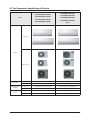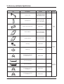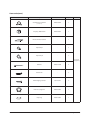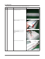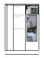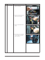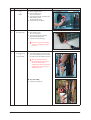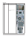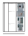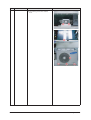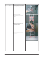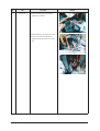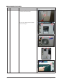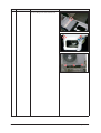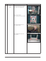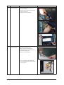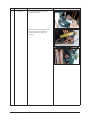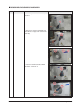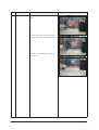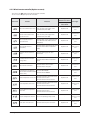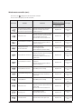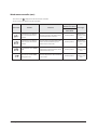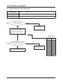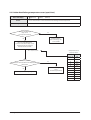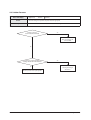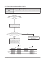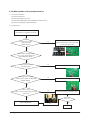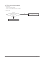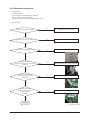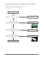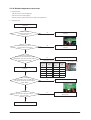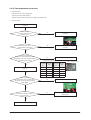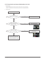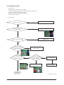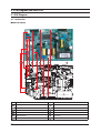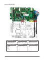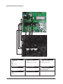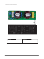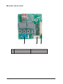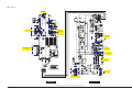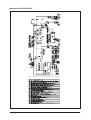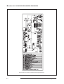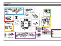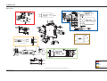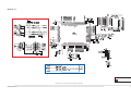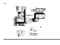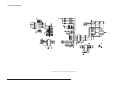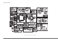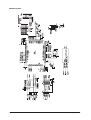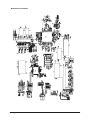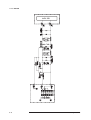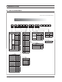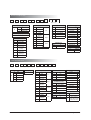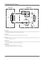
1
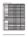
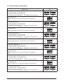
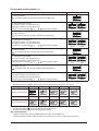
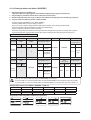
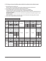
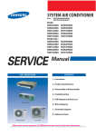
SPLIT-TYPE AIR CONDITIONER
Basic :
MH026FNEA/UH026EAV1
MH052FNEA/UH052EAV1
Model : NS026NHXEA/UH026EAV1
NS035NHXEA/UH035EAV1
NS052NHXEA/UH052EAV1
NS070NHXEA/UH070EAV2
NS026NDXEA/ RC026DHXEA
NS035NDXEA/RC035DHXEA
NS052NDXEA/ RC052DHXEA
NS071NDXEA/RC071DHXEA
Model Code : NS026NHXEA/UH026EAV1
NS035NHXEA/UH035EAV1
NS052NHXEA/UH052EAV1
NS070NHXEA/UH070EAV2
NS026NDXEA/ RC026DHXEA
NS035NDXEA/RC035DHXEA
NS052NDXEA/ RC052DHXEA
NS071NDXEA/RC071DHXEA
SERVICE
AIR CONDITIONER
Manual
CONTENTS
1. Precautions
2. Product Specifications
NS026NHXEA/NS035NHXEA/ NS026NDXEA/ NS035NDXEA
3. Disassembly and Reassembly
4. Troubleshooting
5. PCB Diagram and Parts List
NS052NHXEA/ NS052NDXEA/NS070NHXEA/NS071NDXEA
6. Wiring Diagram
7. Schematic Diagram
8. Reference Sheet
UH026EAV1/UH035EAV1
UH070EAV2/RC071DHXEA
UH052EAV1
RC026/035/052DHXEA
Refer to the service manual in the GSPN(see the rear cover) for the more information.
Contents
11. Precautions ........................................................................................................................................ 1-1
1-1 Precautions for the Service .............................................................................................................
1-1
................................................................................
1-1
...............................................................................................................
1-1
.......................................................................................................................
1-2
.................................................................................................................................................
1-2
1-2 Precautions for the Static Electricity and PL
1-3 Precautions for the Safety
1-4 Disposing of the unit
1-5 Others
12. Product Specifications ............................................................................................................... 2-1
....................................................................................................................
2-1
................................................................................................................
2-2
................................................................................
2-8
2-4 Accessory and Option Specifications ........................................................................................................
2-9
2-1 The Feature of Product
2-2 Specifications of Product
2-3 The Comparative Specifications of Product
3. Disassembly and Reassembly
..............................................................................................
3-1
3-1 Indoor Unit .........................................................................................................................................
3-2
3-2 Outdoor Unit
3-5
.....................................................................................................................................
4. Troubleshooting
............................................................................................................................
4-1
.......................................................................................................
4-1
4-1 Setting Option Setup Method
4-2 Things to check before diagnosis .................................................................................................. 4-10
4-3 Fault Diagnosis by Symptom
.........................................................................................................
5. PCB Diagram and Parts List
4-14
...................................................................................................
5-1
.....................................................................................................................................
5-1
5-1-1 Indoor Unit ..............................................................................................................................
5-1
5-1-2 Outdoor Unit ...........................................................................................................................
5-3
5-1 PCB Diagram
6. Wiring Diagram
..............................................................................................................................
6-1
7. Schematic Diagram ...................................................................................................................... 7-1
8-1 Indoor Unit
........................................................................................................................................
7-1
.....................................................................................................................................
7-2
8-2 Outdoor Unit
1
8. Reference Sheet .............................................................................................................................. 8-1
9-1 Index for Model Name .....................................................................................................................
8-1
..........................................................................................................
8-3
9-2 Refrigerating Cycle Diagram
2
Samsung Electronics
1. Precautions
1-1 Precautions for the Service
OUse the standard parts when replacing the electric parts.
– Confirm the model name, rated voltage, rated current of the electric parts.
ORepair the disconnection of HARNESS securely when repairing the break down.
– If there is any connection error, it causes an abnormal noise and incorrect operation.
OIn case that you assemble or disassemble the products with laying it on the side, do work on the work cloth.
– If not, the exterior of products can be scratched.
ORemove dust and foreign materials from harness, connection part, and inspection part thoroughly when repairing the break
down.
– It protects the danger of fire such as tracking and short.
OTighten tightly the service valve of outdoor unit and the cap of charging valve with a monkey spanner.
OCheck the assembly status of parts after repairing the break down.
– It should be same as the status before repairing.
1-2 Precautions for the Static Electricity and PL
O As the PCB power terminal has a weakness for the static electricity, pay attention to it during the repair and measurement.
– Work with insulation gloves during the repair and measurement of PCB.
O Check the distance between the product and the other electronic appliances such as TV, video, and audio.
It should be over 2m.
– If not, it causes a bad picture quality or a noise.
O Repairing the products by consumer should be strictly prohibited.
– There is a danger of electric shock or fire due to incorrect disassembly.
1-3 Precautions for the Safety
O Do not pull any electric wires and do not touch an auxiliary power switch with a wet hand.
– There is a danger of electric shock or fire.
O In case any wire or power plug has been damaged, replace it to eliminate any possible danger.
O Do not bend the power cord by force and do not put any heavy object on the power cord.
– There is a danger of electric shock or fire.
O Do not use multi socket.
– There is a danger of electric shock or fire.
O Ground the product if necessary.
– Be sure to ground the product if there is any danger of electric leakage due to water or moisture.
O Be sure to turn off the auxiliary power switch or pull out the power plug during replacement or repair
of electric parts.
– There is a danger of electric shock.
O In case the product will not be in use for a long time, the battery of remote control should be kept separately.
– Leakage of inside fluid can cause break down of remote control.
Samsung Electronics
1-1
1-4 Disposing of the unit
O Before throwing out the air conditioner, remove the batteries from the remote control.
O When you dispose of the air conditioner, consult your dealer. If pipes are removed incorrectly, refrigerant may blow out and cause
air pollution. When it contacts with your skin, it can cause skin injury.
O The package of the air conditioner should be recycled or disposed of properly for environmental reasons.
1-5 Others
O
O
O
O
Never store or load the air conditioner upside down or sideways to prevent the damage to the compressor.
Young children or infirm persons should be always supervised when they use the air conditioner.
Max current is measured according to IEC standard for safety.
Current is measured according to ISO standard for energy efficiency.
When installing, make sure there is no leakage. When recovering the refrigerant, ground the compressor first before removing the
connection pipe.If the refrigerant pipe is not properly connected and the compressor works with the service valve open, the pipe
inhales the air and it makes the pressure inside of the refrigerant cycle abnormally high. It may cause explosion and injury.
O Pump Down Procedure (When removing the product)
1) Turn on the air conditioner and select Cool mode to run the compressor for 3 minutes.
2) Release the valve caps on High and Low pressure side.
3) Use L wrench to close the valve on the high pressure side.
4) Approximately 2 minutes after, close the valve on the low pressure side.
5) Stop operation of the air conditioner.
6) Disconnect the pipes.
1-2
Samsung Electronics
2. Product Specifications
2-1 The Feature of Product
Q Catechin Filter
Catechin, extracted from the green tea, is contained in the filter and deactivates captured bacteria and unpleasant odors.
Q Silver Nano Evaporator
Q Deodorizing Filter
Activated carbon is incorporated in the filter, efficiently absorbing cigarette smoke, pet odors, and other unpleasant smells, replacing
them with clean, refreshing air.
Q Anti-Bacterial Cross Fan
Samsung Electronics
2-1
2-2 The Specifications of Product
common
Model
Indoor Unit
Outdoor Unit
Capacity(Min/Nor/ Cooling
Max)
Heating
Cooling
Input
Heating
Cooling
Running Current
Heating
Cooling
Heating
Running Frequency
Cooling(Low/Std/Max)
Heating(Low/Std/Max)
Cooling
Max Capacity
Heating
Cooling
Max Input
Heating
Cooling
Max Running Current
Heating
Power Supply
Cooling
EER
Heating
Refrigerant Control
Refrigerant Charge
extention length ( total )
extention length ( elevation )
standard
Additional Refrigerant Charge
Operation range
Indoor fan motor
Indoor
Indoor Fan
Indoor Fan RPM
Temperature
Controller
Indoor Coil
Set Dimensions
(W*H*D)
Sound Level
2-2
Model
Input
Running Current
Capacitor
Type
No. Used / Diameter
Cooling(H/M/L)
Heating(H/M/L)
NS026NHXEA
UH026EAV1
W
1,200/2,600/3,500
W
1,030/3,500/3,800
W
245/650/1,500
W
200/970/1,150
A
1.6/3.4/7.0
A
1.3/5.0/5.4
Hz
20~85
Hz
20~90
Hz
20/48/85
Hz
20/71/90
W
3,500
W
3,800
W
1,500
W
1,150
A
7.00
A
5.40
Ø,V,Hz 1,220~240,50
W/W
4.00(A)
W/W
3.61(A)
EEV
g, type 950, R410a
m
20
m
15
m
5
g/m
0
-10~43
ć
-15~24
YDK-016S4140-01
W
40
A
0.2
μF/Vac 1.2uF(SSR)
Sirocco Fan
EA/mm 92
rpm
1140 / 1035 / 930
rpm
1210 / 1105 / 1000
Tube Size (OD)
Fin pitch
No. of Rows & Column
Net
Gross
Weight (Net/Gross)
Pressure Level (Cool/Heat)
mm
mm
mm
kg
dB(A)
NS035NHXEA
UH035EAV1
1,200/3,500/3,700
1,040/4,000/4,400
245/1,050/1,500
210/1,170/1,400
1.6/5.1/7.0
1.3/5.8/6.5
20~90
20~95
20/73/90
20/81/95
3,700
4,400
1,500
1,400
7.00
6.50
1,220~240,50
3.33(A)
3.42(B)
EEV
950,R410a
20
15
5
0
-10~43
-15~24
YDK-016S4140-01
40
0.2
1.2uF(SSR)
Sirocco Fan
92
1210 / 1105 / 1000
1280 / 1175 / 1070
Thermistor
Thermistor
7.0
1.3
2*10*640+2*4*620
825x285x189
900×349×252
9/11
43/43
7.0
1.3
2*10*640+2*4*620
825x285x189
900×349×252
9/11
43/43
Samsung Electronics
Model
Compressor
Outdoor
Outdoor Coil
Outdoor fan motor
Outdoor Fan
Indoor Unit
Outdoor Unit
Locked Rotor Amp.
Type
Model
Capacity
Motor Type
Motor Input
Oil Type
Oil Charge
Tube Size (OD)
Fin pitch
No. of Rows & Column
Output
Model
No. of Poles
Running Current
Type
No. Used / Diameter
Discharge
Speed
Other
Sound Level
A
Btu/hr
W
g
mm
w
A
EA/mm
Top / Side
rpm
Pressure Level (Cool/Heat) dB(A)
Net
mm
Set Dimensions
Gross
mm
(W*H*D)
Weight (Net/Gross)
kg
Power supply Cable No.* mm2
Communication Cable
No.* mm2
Liquid Side
inch(mm)
inch(mm)
Connecting Tube (Ø Gas Side
Socket Flare)
Length, std
m
Max length/elevation
m
In Diameter
mm
Drain hose
Out Diameter
mm
mm
Packing Dimension Indoor Unit
(W*H*D)
Outdoor Unit
mm
OPTION CODE
Samsung Electronics
NS026NHXEA
UH026EAV1
Single BLDC
G4C090LUDER
9,300
BLDC
861
FREOL α 68ES-T
320
Φ8
G-Fin, FP1.3
1R24C
25
SIC-52FV-F726-2
8
0.1
Propeller
1/401
Side
800 / 700 / 500(C)
900 / 700 / 600(H)
51/51
790X548X285
938X610X382
35.5/38
1/2.5
1/1.25
1/4’(6.35)
3/8’(9.52)
5
20/15
Φ19
Φ18
810X710X295
938X610X382
027770-13022C
200000-300000
NS035NHXEA
UH035EAV1
Single BLDC
G4C090LUDER
9,300
BLDC
861
FREOL α 68ES-T
320
Φ8
G-Fin, FP1.3
1R24C
25
SIC-52FV-F726-2
8
0.1
Propeller
1/401
Side
850 / 750 / 500(C)
900 / 750 / 600(H)
53/53
790X548X285
938X610X382
35.5/38
1/2.5
1/1.25
1/4’(6.35)
3/8’(9.52)
5
20/15
Φ19
Φ18
810X710X295
938X610X382
027770-15024E
200000-300000
2-3
Indoor Unit
Outdoor Unit
Capacity(Min/Nor/ Cooling
Max)
Heating
Cooling
Input
Heating
Cooling
Running Current
Heating
Cooling
Heating
Running Frequency
Cooling(Low/Std/Max)
Heating(Low/Std/Max)
Cooling
Max Capacity
Heating
Cooling
Max Input
Heating
Cooling
Max Running Current
Heating
Power Supply
Cooling
EER
Heating
Refrigerant Control
Refrigerant Charge
extention length ( total )
extention length ( elevation )
standard
Additional Refrigerant Charge
common
Model
Indoor
Indoor Fan
Indoor Fan RPM
Model
Input
Running Current
Capacitor
Type
No. Used / Diameter
Cooling(H/M/L)
Heating(H/M/L)
W
A
μF/Vac
EA/mm
rpm
rpm
Temperature
Controller
Indoor Coil
Set Dimensions
(W*H*D)
Sound Level
2-4
g, type
m
m
m
g/m
ć
Operation range
Indoor fan motor
W
W
W
W
A
A
Hz
Hz
Hz
Hz
W
W
W
W
A
A
Ø,V,Hz
W/W
W/W
Tube Size (OD)
Fin pitch
No. of Rows & Column
Net
Gross
Weight (Net/Gross)
Pressure Level (Cool/Heat)
mm
mm
mm
kg
dB(A)
NS052NHXEA
UH052EAV1
1,900/5,000/6,050
1,500/6,000/6,250
400/1,400/2,200
340/1,760/3,150
2.6/6.3/9.8
2.3/8.3/14.0
15~65
15~85
15/48/65
15/57/85
6,050
6,250
2,200
3,150
9.80
14.00
1,220~240,50
3.57(A)
3.41(B)
EEV
1450,R410a
50
30
5
30
-15~43
-20~24
KFD-30SX
73
0.33
2.0uF(SSR)
Sirocco Fan
92
1245 / 1070 / 930
1280 / 1105 / 965
NS070NHXEA
UH070EAV2
2,400/7,100/7,600
2,150/8,000/9,950
530/2,350/3,100
500/2,750/4,050
3.2/10.7/14.0
3.0/12.7/17.5
15~73
15~85
15/59/73
15/58/85
7,600
9,950
3,100
4,050
14.00
17.50
1,220~240,50
3.02(B)
2.91(D)
EEV
1900, R410a
50
30
5
30
-15~50
-20~24
KFD-30SX
73
0.33
2.0uF(SSR)
Sirocco Fan
92
1280 / 1105 / 930
1340 / 1140 / 1000
Thermistor
Thermistor
7.0
1.3
2*10*850+2*6*830
1065x298x218
1137X377X299
13/16
48/48
7.0
1.3
2*10*850+2*6*830
1065x298x218
1137X377X299
13/16
50/50
Samsung Electronics
Model
Compressor
Outdoor
Outdoor Coil
Outdoor fan motor
Outdoor Fan
Indoor Unit
Outdoor Unit
Locked Rotor Amp.
Type
Model
Capacity
Motor Type
Motor Input
Oil Type
Oil Charge
Tube Size (OD)
Fin pitch
No. of Rows & Column
Output
Model
No. of Poles
Running Current
Type
No. Used / Diameter
Discharge
Speed
Other
Sound Level
Pressure Level (Cool/Heat)
Net
Set Dimensions
Gross
(W*H*D)
Weight (Net/Gross)
Power supply Cable Communication Cable
Liquid Side
Connecting Tube (Ø Gas Side
Socket Flare)
Length, std
Max length/elevation
In Diameter
Drain hose
Out Diameter
Packing Dimension Indoor Unit
(W*H*D)
Outdoor Unit
OPTION CODE
Samsung Electronics
A
Btu/hr
W
g
mm
w
A
EA/mm
Top / Side
rpm
dB(A)
mm
mm
kg
No.* mm2
No.* mm2
inch(mm)
inch(mm)
m
m
mm
mm
mm
mm
NS052NHXEA
UH052EAV1
11.0
Twin BLDC
G8T200FUAEW
20,000
BLDC
1852
POE
700
Φ7
1.3
2R28C
40
SIC-67FV-F135-2/3
4
0.25
Propeller
1/420
Side
1000 / 850 / 520(C)
1000 / 900/ 600(H)
58/58
880x638x310
1023x704x413
50 / 53
2x3.5
4x1.25
1/4”(6.35)
1/2”(12.7)
5
50/30
Φ19
Φ18
1074x294x726
1023x704x413
026770-19025C
200000-300000
NS070NHXEA
UH070EAV2
13.0
Twin BLDC
G8T260FUAEW
26,500
BLDC
2454
POE
700
Φ7
1.3
2R36C
65
DL-95835SSOA-5
4
0.45
Propeller
1/460
Side
1000 / 850/ 650(C)
1000 / 780 / 650(H)
58/58
880x798x310
1038x861x406
57 / 61
2x3.5
4x1.25
1/4”(6.35)
5/8”(15.88)
5
50/30
Φ19
Φ18
1390x345x575
1038x861x406
027770-1C026C
200000-300000
2-5
Indoor Unit
Outdoor Unit
Capacity(Min/Nor/ Cooling (Low/Std/Max)
Max)
Heating (Low/Std/Max)
Cooling (Low/Std/Max)
Input
Heating (Low/Std/Max)
Cooling (Low/Std/Max)
Running Current
Heating (Low/Std/Max)
Cooling(Low/Std/Max)
Running Frequency
Heating(Low/Std/Max)
Power Supply
Cooling
EER
Heating
Refrigerant Control
Refrigerant Charge
extention length ( total )
extention length ( elevation )
standard
Model
Indoor fan motor
Capacitor
Type
Indoor Fan
Diameter
Cooling(H/M/L)
Indoor Fan RPM
Heating(H/M/L)
Temperature
Controller
Tube Size (OD)
Fin pitch
Indoor Coil
No. of Rows & Column
Indoor
common
Model
Set Dimensions
(W*H*D)
Sound Level
Compressor
Outdoor Coil
Outdoor Motor
Outdoor Fan
Sound Level
Set Dimensions
(W*H*D)
2-6
W
W
W
W
A
A
Hz
Hz
Ø,V,Hz
W/W
W/W
g, type
m
m
m
μF/Vac
mm
rpm
rpm
mm
NS026NDXEA
RC026DHXEA
1,200/2,600/3,500
1,030/3,500/3,800
245/650/1500
200/970/1150
1.6/3.4/7.0
1.3/5.0/5.4
20/50/75
20/71/90
1,220~240,50
4.00
3.61
EEV
950, R410a
20
15
5
KSFD-18SX
1.2uF
Cross flow
Φ92
1140/1035/930
1210/1105/1000
NS035NDXEA
RC035DHXEA
1,200/3,500/3,700
1,040/4,000/4,400
245/1050/1500
210/1170/1400
1.6/5.1/7.0
1.3/5.8/6.5
20/73/88
20/81/95
1,220~240,50
3.33
3.42
EEV
950, R410a
20
15
5
KSFD-18SX
1.2uF
Cross flow
Φ92
1210/1105/1000
1280/1175/1070
Thermistor
Thermistor
7.0
1.3
Φ7*2R*10S*L640&
Φ7*2R*4S*L620
825*189*285
904*263*353
9/11
43/43
Single BLDC
G4C090LUDJR
320cc, POE
Φ8
1.3
2R24S
7.0
1.3
Φ7*2R*10S*L640&
Φ7*2R*4S*L620
825*189*285
904*263*353
9/11
43/43
Single BLDC
G4C090LUDJR
320cc, POE
Φ8
1.3
2R24S
SIC-67FV-F135-8
SIC-67FV-F135-8
Net
Gross
Weight (Net/Gross)
Pressure Level (Cool/Heat)
Type
Model
Oil Type
Tube Size (OD)
Fin pitch
No. of Rows & Column
Model
Type
No. Used / Diameter
Discharge
mm
mm
kg
dB(A)
Propeller
EA/mm
1/460
Top / Side Side
Propeller
1/460
Side
Speed
rpm
900/760/150(C/H)
900/800/150(C/H)
Pressure Level (Cool/Heat)
Net
Gross
Weight (Net/Gross)
dB(A)
mm
mm
kg
51/51
790*548*285
926*655*382
33/37
53/53
790*548*285
926*655*382
33/37
mm
Samsung Electronics
Indoor Unit
Outdoor Unit
Capacity(Min/Nor/ Cooling (Low/Std/Max)
Max)
Heating (Low/Std/Max)
Cooling (Low/Std/Max)
Input
Heating (Low/Std/Max)
Cooling (Low/Std/Max)
Running Current
Heating (Low/Std/Max)
Cooling(Low/Std/Max)
Running Frequency
Heating(Low/Std/Max)
Power Supply
Cooling
EER
Heating
Refrigerant Control
Refrigerant Charge
extention length ( total )
extention length ( elevation )
standard
Model
Input
Indoor fan motor
Running Current
Capacitor
Type
Indoor Fan
No. Used / Diameter
Cooling(H/M/L)
Indoor Fan RPM
Heating(H/M/L)
Temperature
Controller
Tube Size (OD)
Fin pitch
Indoor Coil
No. of Rows & Column
Indoor
common
Model
Set Dimensions
(W*H*D)
Sound Level
Compressor
Outdoor
Outdoor Coil
Outdoor Motor
Outdoor Fan
Sound Level
Set Dimensions
(W*H*D)
Samsung Electronics
W
W
W
W
A
A
Hz
Hz
Ø,V,Hz
W/W
W/W
g, type
m
m
m
W
A
μF/Vac
EA/mm
rpm
rpm
mm
NS052NDXEA
RC052DHXEA
1,900/5,000/6,050
1,500/6,000/6,250
400/1560/2200
340/1760/315
2.6/7.2/9.8
2.3/8.3/14.0
15/67/82
15/72/100
1,220~240,50
3.21
3.41
EEV
1800, R410a
30
20
5
KFD-30SX
73
0.33
2.0uF(SSR)
Sirocco Fan
8Pole, Φ94
1245/1070/930
1280/1105/965
NS071NDXEA
RC071DHXEA
2,200/7,100/8,000
1,900/8,000/9,000
350/2360/4000
350/2850/4000
2.0/10.5/21.0
2.0/13.0/21.0
15/77/82
15/83/105
1,220~240,50
3.01
2.81
EEV
1800, R410a
50
30
5
KFD-30SX
73
0.33
2.0uF(SSR)
Sirocco Fan
8Pole, Φ94
900/820/130
900/790/130
Thermistor
Thermistor
7.0
1.3
Φ7*2R*10S*L850&
Φ7*2R*6S*L830
1065x298x218
1137X377X299
13/16
48/48
13.0
Twin BLDC
UG4T150FUDJQ
650cc, POE
Φ8
1.3
2R24C
7.0
1.3
Φ7*2R*10S*L850&
Φ7*2R*6S*L830
1065x298x218
1137X377X299
13/16
50/50
13.0
Twin BLDC
UG4T200FUAE4
26,500
650cc, POE
Φ7
1.3
2R36C
FMBC531SSK
Propeller
1/460
Side
900/820/130
1000 / 780 / 650(H)
58/58
880x798x310
1023×891×413
54.5/59
Net
Gross
Weight (Net/Gross)
Pressure Level (Cool/Heat)
Locked Rotor Amp.
Type
Model
Capacity
Oil Type
Tube Size (OD)
Fin pitch
No. of Rows & Column
Model
Type
No. Used / Diameter
Discharge
mm
mm
kg
dB(A)
A
EA/mm
Top / Side
Propeller
1/460
Side
Speed
rpm
1000/1000/320(C/H)
Pressure Level (Cool/Heat)
Net
Gross
Weight (Net/Gross)
dB(A)
mm
mm
kg
58/58
790*548*285
926*655*382
38.5/42.5
Btu/hr
mm
SIC-67FV-F135-8
2-7
2-3 The Comparative Specifications of Product
NS026NDXEA/RC026DHXEA
NS035NDXEA/RC035DHXEA
Item
NS052NDXEA/RC052DHXEA
NS071NDXEA/RC071DHXEA
NS026NHXEA/UH026EAV1
NS035NHXEA/UH035EAV1
NS052NHXEA/UH052EAV1
NS070NHXEA/UH070EAV2
(Basic)
Indoor Unit
Design
Outdoor Unit
Indoor Unit
9.0kg /13kg
9.0kg/13kg
Outdoor Unit
33kg/42.5kg/54.5kg
51kg/53kg/58kg
Indoor Unit
825*189*285 mm / 1065*218*298mm
825*189*285 mm / 1065*218*298mm
Outdoor Unit
790*548*285mm/ 880x798x310mm
790*548*285mm/880*638*310mm/880*798*310mm
Indoor Unit
43dB↓/ 48dB↓
43dB↓/ 45dB↓/ 50dB↓
Outdoor Unit
51dB↓/ 53dB↓/ 58dB↓
51dB↓/ 53dB↓/ 58dB↓
Net Weight
Outer Dimension
(WxHtxD)
Noise
2-8
Samsung Electronics
2-4 Accessory and Option Specifications
Item
Descriptions
Code-No.
Q'TY
Installation Plate
DB97-02851C(7726/3577)
DB90-02738A(7752/7077)
DB90-02738A(7707177)
1
Remote Control
DB93-06335T(*NHXEA)
DB93-11115N(*NDXEA)
1
Batteries for Remote Control
DB47-90024A
2
Owner’s Manual
DB98-31944A(*NHXEA)
DB98-32405A(*NDXEA)
1
Installation Manual
DB98-31943A(*NHXEA)
DB98-32736A(*NDXEA)
1
Drain Plug
DB67-00477A
1
'JMUFS
3FTFU
TIONS
OWNER'S INSTRUC
INSTRUCCIONES
MANUAL DE
PER L'USO
ISTRUZIONIINSTRU‚Í
ES
MANUAL DE ATION
MANUEL D'UTILISEISUNG
GEBRAUCHSANW
Air ConditionerSplit
Splut-type Room
domĿstico sistema
ad unitˆ Separate
Aire acondicionado
d'aria per ambienti
Split
Condizionatorede ar condicionado tipo
Aparelho
type sĿparĿ
Climatiseur de
e
Geteilte raumklimaanlag
Remark
Indoor
Unit
Outdoor
Unit
Rubber Leg
DB73-20134A
4
Assembly Pipe, ø6.35mm
(6626/35/52/70/07166)
DB62-02672D
1
3-wire Assembly Cable
-
1
5-wire Assembly Cable
-
1
DB62-02672E
1
Assembly Pipe, ø9.52mm
(6626/3566)
Assembly Pipe, ø12.70mm
(665266)
Samsung Electronics
Accessory
Box(option)
DB62-02672F
2-9
Accessories(cont.)
Item
Descriptions
Code-No.
Q'TY
DB62-02672H
1
Vinyl Tape, Width 80mm
DB72-00459A
1
PE T3 Foam Tube insulation
-
1
Pipe Clamp A
-
3
Pipe Clamp B
-
3
Assembly Pipe, ø15.88mm
(667066)
Remark
Accessory
Box(option)
2-10
Cable-Tie
DB65-10088C
4
Cement Nail
-
6
M4x16 Tapping ScrewsO
6002-000215
6
Drain Hose, length 2m
DB67-00274A
1
Putty 100g
DB98-10568A
1
Samsung Electronics
3. Disassembly and Reassembly
QNecessary Tools
Item
Remark
+SCREW DRIVER
MONKEY SPANNER
Samsung Electronics
3-1
3-1 Indoor Unit
Stop operation of the air conditioner and remove the power cord before repairing the unit.
No
Parts
1
Front Grille
Procedure
Remark
1) Stop the air conditioner operation and
shut off the main power.
2) Open the Front Grille by pulling right and
left sides of the hook.
3) Loosen 1 of the right screw and detach
the Terminal Cover.
4) Detach the thermistor from the Front
Grille.
5) Loosen 3 fixing screws of Front Grille.
3-2
Samsung Electronics
No
Parts
Procedure
Remark
6) Unlock 3 hooks to fix Panel Front and
Tray Drain.
7) Unlock 3 hooks to fix Panel Front and
Back-Body.
2
Control-In
(Main PCB)
1) Take all the connector of PCB upper side
out. (Inclusion Power Cord)
2) Detach the outdoor unit connection wire
from the Terminal Block.
3) Loosen 4 fixing screws of Ass’y Control-In.
3
Tray Drain
1) Pull Tray Drain out from the Back Body.
Samsung Electronics
3-3
No
Parts
4
Heat Exchanger
Procedure
Remark
1) Loosen 2 fixing earth screws of right side.
2) Detach the Connection Pipe.
3) Detach the Holder Pipe at the rear side.
4) Loosen the 4 fixing screws of right and left
side.
5) Lifting the Heat Exchanger up a little to
push the up side for separation from the
indoor unit.
5
3-4
Fan Motor
&
Cross Fan
1) Loosen the fixing screw.
2) Detach the Fan Motor from the Fan.
3) Detach the Fan From the left Holder
Bearing.
Samsung Electronics
3-2 Outdoor Unit
Stop operation of the air conditioner and remove the power cord before repairing the unit.
Q UH035EAV1/UH026EAV1
No
Parts
1
Common Work
Procedure
Remark
Before disassembly, please make sure to
shut off the power.
1) Separate fixing screw in the Cover Side.
(Use +Screw Driver.)
2) Undo the 4 fixing screws on the left
and right cabinet Side Edges then
undo the screws on the lower front to
separate the Cabinet Front.
(Use +Screw Driver.)
3) Separate the Cabinet Front as shown on
the right picture.
4) Undo fixing screw to remove Plate
Control Out on the Cabinet Side RH.
(Use +Screw Driver.)
Samsung Electronics
3-5
No
Parts
Procedure
Remark
5) Undo 2 fixing screws on the backside
of the Cabinet Side RH.
(Use +Screw Driver.)
6) Undo 3 fixing screws to assemble
Bracket Valve on the Cabinet Side RH.
(Use +Screw Driver.)
7) Undo 2 fixing screws on the Cabinet
Side LF. (Use +Screw Driver.)
3-6
Samsung Electronics
No
Parts
2
Ass'y Control Out
Procedure
Remark
1) Separate the Motor wire from the PCB
of the Ass’y Control Out.
2) Separate several Connectors from the
PCB of the Ass’y Control Out.
3) Separate 2 Connect Wires from the
Reactor.
4) Undo a fixing screw to assemble the
Ass’y Control Out on the Partition.
(Use +Screw Driver.)
Samsung Electronics
3-7
No
Parts
Procedure
3
Fan
&
Motor
1) Release refrigerant first.
2) Undo the fixing screw.
(Use +Screw Driver.)
3) Separate the induction and outlet pipes
with a Welding Torch.
(Use Monkey Spanner.)
4) Separate the Fan and Motor.
4
Heat Exchanger
Remark
1) Undo 2 fixing screws.
(Use +Screw Driver.)
2) Separate the induction and outlet
pipes with a Welding Torch.
3) Separate the Heat Exchanger.
Please wear gloves when working
as there is a possibility of cutting
your hand.
5
Ass'y Valve 4 way
&
Ass'y Valve EEV
1) Undo 4 fixing bolts to assemble a Valve
Service on the Bracket Valve as shown in
the right picture. (Use Monkey Spanner.)
When separating Compressor,
Heat Exchanger and pipes please
ensure that Compressor is
completely free from any remaining
refrigerant then separate all pipes
with welding torch.
Q Ass'y Valve 4 Way
1) Separate 3 welded parts.
3-8
Samsung Electronics
No
Parts
Procedure
Remark
Q Ass'y Valve EEV
1) Separate 1 welded parts.
6
Compressor
Samsung Electronics
1) Undo nuts on the Terminal Cover.
2) Separate the Terminal Cover and then
Connect Wires from the Compressor.
3) Separate the Felt Comp Sound.
4) Undo 3 bolts on the flow of the
Compressor as shown in the right-hand
picture. (Use Monkey Spanner.)
3-9
Q UH052EAV1
No
Parts
1
Common Work
Procedure
Remark
1) Loosen 1 fixing screw of the CoverControl and detach the Cover Control.
2) Loosen fixing screws and detach the
Cabinet-Upper.
3-10
Samsung Electronics
No
Parts
Procedure
Remark
3) Loosen 1 screw fixed to assemble Control
Box with Cabinet-Side RH.
4) Loosen 6 fixing screws and detach the
Cabinet-Side RH.
5) Loosen 2 screws fixed on the Guide
Condenser.
Samsung Electronics
3-11
No
Parts
Procedure
Remark
6) Loosen fixing screws of the Cabinet
Front.
3-12
Samsung Electronics
No
Parts
Procedure
2
Fan
&
Motor
1) Detach the Nut Flange like the picture
on the right side. (Turn counterclockwise
because the screw is right-handed.)
Remark
2) Detach the Fan Propeller.
3) Loosen 4 fixing screws to detach the
Motor.
4) Disconnect the wire between ASS’Y
Control Out and Motor.
5) Loosen 2 fixing bolts and detach the
Bracket Motor.
Samsung Electronics
3-13
No
Parts
3
ASS’Y Control Out
Procedure
Remark
1) Detach several connectors from the
ASS’Y Control Out.
2) Detach several connectors from the PCB
of ASS’Y Control Out.
3) Pull up the ASS’Y Control Out.
4
Heat Exchanger
1) Release the refrigerant at first.
2) Loosen fixing screw.
3) Disassemble the pipes in both inlet and
outlet with welding torch.
4) Detach the Heat Exchanger.
5) Loosen 4 bolts fixed to assemble Valve
Service with Bracket Valve like the picture
on the right side.
3-14
Samsung Electronics
No
Parts
5
Compressor
Procedure
Remark
1) Loosen the fixing nut and detach the
Compressor Lead Wire.
2) Disassemble the Felt Compressor Sound.
3) Loosen the 3 bolts at the bottom of
Compressor like the picture on the right
side.
Samsung Electronics
3-15
QUH070EAV2/RC071DHXEA
No
Parts
Procedure
1
Common Work
1) Loosen 1 fixing screw of the Cover-Control
and detach the Cover Control.
Remark
2) Loosen each 7 fixing screws and detach
the Cabinet Upper.
3-16
Samsung Electronics
No
Parts
Procedure
Remark
3) Loosen 1 screw fixed to assemble
Control Box with Cabinet-Side RH.
4) Loosen fixing screws and detach the
Cabinet-Side RH.
5) Loosen 2 screws fixed on the Guide
Condenser.
Samsung Electronics
3-17
No
Parts
Procedure
Remark
6) Loosen fixing screws of the Cabinet Front.
3-18
Samsung Electronics
No
Parts
2
Fan
&
Motor
Procedure
Remark
1) Detach the Nut Flange like the picture on
the right side. (Turn counter clockwise
because the screw is right-handed.)
2) Detach the Fan Propeller.
3) Loosen 4 fixing screws to detach the Motor.
4) Disconnect the wire between ASS'Y
Control Out and Motor.
5) Loosen 2 fixing bolts and detach the
Bracket Motor.
Samsung Electronics
3-19
No
Parts
Procedure
3
ASS'Y Control Out
1) Detach several connectors from the
ASS'Y Control Out.
2) Detach several connectors from the PCB
of ASS'Y Control Out.
3) Pull up the ASS'Y Control Out.
4
Heat Exchanger
1) Release the refrigerant at first.
2) Loosen fixing screw on both sides.
3) Disassemble the pipes in both inlet and
outlet with welding torch.
4) Detach the Heat Exchanger.
Remark
5) Loosen 4 bolts fixed to assemble Valve
Service with Bracket Valve like the picture
on the right side.
3-20
Samsung Electronics
No
Parts
5
Compressor
Procedure
Remark
1) Loosen the fixing nut and detach the
Compressor Lead Wire.
2) Disassemble the Felt Compressor Sound.
3) Loosen the 3 bolts at the bottom of
Compressor like the picture on the
right side.
Samsung Electronics
3-21
QRC026DHXEA/ RC035DHXEA/ RC052DHXEA
No
Parts
Procedure
1
common work
1) loosen 1 pcs screw of cover control,and
detach it.
Remark
2) loosen 5 pcs screws on both right and
left cabniet side edges and to detach the
cover-top
3) Loosen 7 screwsfixed to disassemble
cabi-front , and detach it.
3-22
Samsung Electronics
No
Parts
common work
Procedure
Remark
4) loosen 7 screws to disassemble the cabiright ,and detach it.
5) loosen 2 screws to disassemble steel-bar.
6) loosen 3 screws to disassemble cabi-left.
Samsung Electronics
3-23
No
Parts
Procedure
2
fan&motor
1) loosen 1 screw as indication and detached
the fan.
Remark
2) loosen 4 pcs motor screws and disconnect
the wire betwwen assy control out and motor.
3) loosen 2 pcs bracket-motor screw and
detach it.
3-24
Samsung Electronics
No
Parts
3
assy control out
1) lossen fixing 1 screw from cover -control
2) detach several connections from assy control out, take out assy control out.
4
Heat exchanger
1) Release the refrigerant at first
2) Looosen fixing screw on both side.
3) disaessembly the pipes in both inlet and
outlet with welding torch.
4) detach the heat exchanger.
Samsung Electronics
Procedure
Remark
3-25
No
Parts
5
compressor
Procedure
Remark
1) disconnect the compressor lead wire .
2)disassembly the felt comp sound.
loosen the 3 bolts at the bottom of
3-26
Samsung Electronics
4. Troubleshooting
4-1 Setting Option Setup Method
4-1-1 Type A (Setting Option)
ex) Option No. :
Step 1 : Enter the Option Setup mode.
1st Take out the batteries of remote control.
2nd Press the temperature
the battery again.
button simultaneously and insert
3rd Make sure the remote control display shown as
.
'JMUFS
3FTFU
Step 2 : Enter the Option Setup mode and select your option according to the following procedure.
Feature
1
Display
Auto
The default value is
.
Auto
button, the display panel reads
Auto °Cool
Every time you push the
°Dry °Fan °Heat , OFF Auto °Cool °Dry °Fan °Heat repeatedly.
Auto
2
Push the
button to set the display panel to
.
Every time you push the button, the display panel reads
°...... ° ° ° ° ° ° ° repeatedly.
'JMUFS
3FTFU
3
button to
Push the
Cool
Auto
° ° °
.
Cool
2
4
4
6
1
6
3
Push the
5
Every time you push the 10button, the display panel reads
°...... ° ° ° ° ° ° ° repeatedly.
4
Push the
button to set the display panel to
button to set the display panel to
.
.
Every time you push the button, the display panel reads
°...... ° ° ° ° ° ° ° repeatedly.
5
° ° °
Cool
° ° °
Dry
Push the
button to
.
Dry
button to set the display panel to
Push the
Every time you push the
°...... °
6
Push the
° ° °
° ° ° ° ° ° repeatedly.
Every time you push the
Samsung Electronics
button, the display panel reads
button to set the display panel to
°...... °
.
.
button, the display panel reads
Dry
° ° °
° ° ° ° ° ° repeatedly.
4-1
Feature
7
Display
Fan
Push the
button to
.
Fan
button to set the display panel to
Push the
.
Fan
Every time you push the
°...... °
8
'JMUFS
3FTFU
8
8
10
button to set the display panel to .
°...... °
7
9
° ° °
° ° ° ° ° ° repeatedly.
Every time you push the
11
10
Push the
button, the display panel reads
Fan
button, the display panel reads
° ° °
° ° ° ° ° ° repeatedly.
Heat
Push the
button to
.
9
Push the
button to set the display panel to
Every time you push the
°...... °
10
button, the display panel reads
° ° °
° ° ° ° ° ° repeatedly.
Auto
Push the
button to
Push the
°...... °
Push the
.
button to set the display panel to
Every time you push the
11
Heat
.
button, the display panel reads
° ° °
° ° ° ° ° ° repeatedly.
button to set the display panel to
Every time you push the
°...... °
Auto
.
.
Auto
button, the display panel reads
° ° °
° ° ° ° ° ° repeatedly.
Step 3 : Upon completion of the selection, check you made right selections.
Press the Mode
Selection key to set the display part and check the display part.
° The display part shows like below when each time you press Mode button .
Auto
Cool
Dry
Fan
Heat
Auto
Step 4 : Pressing the ON/OFF button (
)
When pressing the operation ON/OFF key with the direction of remote control for unit, the sound ’’Ding’’ or ’’Diriring’’
is heard and the OPERATION ICON(
) lamp of the display is flickering at the same time, then the input of option is completed.
(If the diriring sound isn’t heard, try again pressing the ON/OFF button.)
Step 5 : Unit operation test-run
First, Remove the battery from the remote control.
Second, Re-insert the battery into the remote control.
Third, Press ON/OFF key with the direction of remote control for set.
t&SSPS.PEF
1st
2nd
4-2
If all lamps of indoor unit are flickering, Plug out, plug in power plug again and press ON/OFF key to retry.
If the unit is not working properly or all lamps are continuously flickering after setting the option code, see if the
correct option code is set up for its model.
Samsung Electronics
4-1-2 Setting an indoor unit address and installation option
▶ Set the indoor unit address and installation option with remote controller option.
Set the each option separately since you cannot set the ADDRESS setting and indoor unit installation setting option at the
same time.You need to set twice when setting indoor unit address and installation option.
▶ Please use the proper wireless remocon which can set 24 digit option code. Following is the instructions of setting option
code with wireless remocon of MR-DH00. (MR-AH01 can be used for operating but cannot be used for setting the installation
option because only 12 digit option setting is available.
▶ Please refer to the wired remocon installation manual for setting with the wired remocon.
4-1-2-1 The procedure of setting option
Entering mode for
setting option
Option setting mode
Mode change
High Temp Button
High Fan Button
Low Temp Button
Low Fan Button
Step 1. Entering mode to set option
1. Remove batteries from the remote controller.
2. Insert batteries and enter the option setting mode while pressing High Temp button and Low Temp button.
3.
Check if you have entered the option setting status.
Step 2. The procedure of option setting
After entering the option setting status, select the option as listed below.
Option setting is available from SEG1 to SEG 24
t 4 &(4&(4&(4&(BSFOPUOFFEUPCFTFUBU.3%)5IFZBSFUIFQBHFPQUJPOTXIJDIXFSFVTFEBUUIF
previous other remocons.
t 4FUUIFFBDICJUPQUJPODPEFJOPSEFSFYDFQUQBHFPQUJPOT
For example : SEG2, 3 SEG4, 5 SEG6, 8 SEG9, 10 SEG11, 12 SEG 14, 15 SEG 16, 17 SEG 18, 20
SEG 21, 22 SEG23, 24.
SEG1 SEG2 SEG3 SEG4 SEG5 SEG6 SEG7 SEG8 SEG9 SEG10 SEG11 SEG12
0
X
X
X
X
X
1
X
X
X
X
X
SEG13 SEG14 SEG15 SEG16 SEG17 SEG18 SEG19 SEG20 SEG21 SEG22 SEG23 SEG24
2
X
X
X
X
X
3
X
X
X
X
X
Samsung Electronics
On(SEG1~12)
Off(SEG13~24)
4-3
4-1-2-2 The procedure of setting option
Option setting
1. Setting SEG2, SEG3 option
Press Low Fan button(∨) to enter SEG2 value.
Press High Fan button(∧) to enter SEG3 value.
Each time you press the button,
…
will be selected in rotation.
Status
SEG2
SEG3
SEG4
SEG5
SEG6
SEG8
SEG9
SEG10
SEG11
SEG12
SEG14
SEG15
2. Setting Cool mode
Press Mode button to be changed to Cool mode in the ON status.
3. Setting SEG4, SEG5 option
Press Low Fan button(∨) to enter SEG4 value.
Press High Fan button(∧) to enter SEG5 value.
Each time you press the button,
…
will be selected in rotation.
4. Setting Dry mode
Press Mode button to be changed to DRY mode in the ON status.
5. Setting SEG6, SEG8 option
Press Low Fan button(∨) to enter SEG6 value.
Press High Fan button(∧) to enter SEG8 value.
…
Each time you press the button,
will be selected in rotation.
6. Setting Fan mode
Press Mode button to be changed to FAN mode in the ON status.
7. Setting SEG9, SEG10 option
Press Low Fan button(∨) to enter SEG9 value.
Press High Fan button(∧) to enter SEG10 value.
Each time you press the button,
…
will be selected in rotation.
8. Setting Heat mode
Press Mode button to be changed to HEAT mode in the ON status.
9. Setting SEG11, SEG12 option
Press Low Fan button(∨) to enter SEG11 value.
Press High Fan button(∧) to enter SEG12 value.
…
will be selected in rotation.
Each time you press the button,
10. Setting Auto mode
Press Mode button to be changed to AUTO mode in the OFF status.
11. Setting SEG14, SEG15 option
Press Low Fan button(∨) to enter SEG14 value.
Press High Fan button(∧) to enter SEG15 value.
Each time you press the button,
…
will be selected in rotation.
4-4
Samsung Electronics
The procedure of setting option (cont.)
Option setting
Status
12. Setting Cool mode
Press Mode button to be change to Cool mode in the OFF status.
13. Setting SEG16, SEG17 option
Press Low Fan button(∨) to enter SEG16 value.
Press High Fan button(∧) to enter SEG17 value.
…
will be selected in rotation.
Each time you press the button,
SEG16
SEG17
SEG18
SEG20
SEG21
SEG22
SEG23
SEG24
14. Setting Dry mode
Press Mode button to be change to Dry mode in the OFF status.
15. Setting SEG18, SEG20 option
Press Low Fan button(∨) to enter SEG18 value.
Press High Fan button(∧) to enter SEG20 value.
Each time you press the button,
…
will be selected in rotation.
16. Setting Fan mode
Press Mode button to be change to Fan mode in the OFF status.
17. Setting SEG21, SEG22 option
Press Low Fan button(∨) to enter SEG21 value.
Press High Fan button(∧) to enter SEG22 value.
…
will be selected in rotation.
Each time you press the button,
18. Setting Heat mode
Press Mode button to be change to HEAT mode in the OFF status.
19. Setting SEG23, SEG24 mode
Press Low Fan button(∨) to enter SEG23 value.
Press High Fan button(∧) to enter SEG24 value.
…
will be selected in rotation.
Each time you press the button,
Step 3. Check the option you have set
After setting option, press
Option
button to check whether the option code you input is correct or not.
[SEG2,3]
[SEG4,5]
[SEG6,8]
[SEG9,10]
[SEG11,12]
[SEG14,15]
[SEG16,17]
[SEG18,20]
[SEG21,22]
[SEG23,24]
Remote Controller Display
Option
Remote Controller Display
Step 4. Input option
with the direction of remote control for set.
Press operation button
For the correct option setting, you must input the option twice.
Step 5. Check operation
1. Reset the indoor unit by pressing the RESET button of indoor unit or outdoor unit.
2. Take the batteries out of the remote controller and insert them again and then press the operation button.
Samsung Electronics
4-5
4-1-2-3 Setting an indoor unit address (MAIN/RMC)
1. Check whether power is supplied or not.
- When the indoor unit is not plugged in, there should be additional power supply in the indoor unit.
2. The panel(display ) should be connected to an indoor unit to receive option.
3. Before installing the indoor unit, assign an address to the indoor unit according to the air conditioning system plan.
4. Assign an indoor unit address by wireless remote controller.
-The initial indoor unit ADDRESS is set as "MAIN : 0, RMC : 0".
-Set Main and RMC Address only the setting is required.
-There is no need to assign the indoor unit Main Address if the outdoor unit is addressing automatically.
The indoor unit Main address will follow the outdoor unit's automatically.
-Assign 12 digit when setting the indoor unit address.
-No need to assign SEG4, 5, 8, 10 which are non applicable. Even though those segments are set, they will be ignored.
-If you set the applicable segments with numbers other than the indiciated, the initial setting will be maintained.
Option No. : 0AXXXX-1XXXXX-2XXXXX-3XXXXX
Option
SEG1
SEG2
SEG3
Explanation
PAGE
MODE
Setting Main address
Indication Details Indication Details
Indication
and Details
0
Option
SEG7
Explanation
PAGE
Details
0
No Main
address
1
Main address
setting mode
A
SEG8
SEG9
RESERVED
Indication
Details
0
No RMC address
1
RMC address
setting mode
1
SEG5
SEG6
The unit digit of
an indoor unit
Indication Details
RESERVED
RESERVED
0~3
SEG10
Setting RMC address
Indication Details
Indication
and Details
Indication
SEG4
A single
digit
SEG11
SEG12
Group
channel(*16)
Group address
Indication Details Indication Details
RESERVED
RMC1
0~2
RMC2
0~F
t8IFOi"w_w'wJTFOUFSFEUP4&(_UIFJOEPPSVOJU."*/"%%3&44JTOPUDIBOHFE
t*GZPVTFUUIF4&(BTUIFJOEPPSVOJUXJMMNBJOUBJOUIFQSFWJPVT."*/"%%3&44FWFOJGZPVJOQVUUIFPQUJPOWBMVFPG4&(
t*GZPVTFUUIF4&(BTUIFJOEPPSVOJUXJMMNBJOUBJOQSFWJPVT3.$"%%3&44FWFOJGZPVJOQVUUIFPQUJPOWBMVFPG4&(_
Example) If you want to set as "MAIN : 3, CHANNEL : 1, RMC : B",
SEG1
SEG2
SEG3
SEG4
0
A
1
SEG7
SEG8
SEG9
SEG10
1
1
assign option codes except SEG 1, 7 which are page options.
4-6
SEG5
SEG11
1
SEG6
3
SEG12
B
Samsung Electronics
4-1-2-4 Setting an indoor unit installation option (suitable for the condition of each installation location)
1. Check whether power is supplied or not.
- When the indoor unit is not plugged in, there should be additional power supply in the indoor unit.
2. The panel(display ) should be connected to an indoor unit to receive option.
3. Set the installation option according to the installation condition of an air conditioner.
- The default setting of an indoor unit installation option is “02000-100000-200000-300000”.
- Individual control of a remote controller(SEG20) is the function that controls an indoor unit individually when there is
more than one indoor unit.
- No need to assign SEG3, 6, 9, 10, 11, 16, 21, 22, 23, 24 which are non applicable. Even though those segments are set,
they will be ignored.
- If you set the applicable segments with numbers other than the indiciated, the initial setting will be maintained.
4. Set the indoor unit option by wireless remote controller.
Option No. : 02XXXX-1XXXXX-2XXXXX-3XXXXX
Option
SEG1
SEG2
Explanation
PAGE
MODE
Indication Indication Details Indication Details
and
0
2
Details
Option
SEG7
SEG8
Explanation
PAGE
Use of drain pump
SEG3
RESERVED
SEG9
SEG4
SEG5
SEG6
Use of external
temperature sensor
Use of central
control
RPM setting
compensation
Indication Details Indication Details
0
Disuse
0
Disuse
1
Use
1
Use
SEG10
SEG11
0. Not used
1. High ceiling mode
2. High ceiling kit
3. Low noise operation
mode
SEG12
Master / Slave
Indication Details Indication Details
Indication Details
RESERVED
RESERVED
RESERVED
0
Disuse
0
slave
Indication
1
Use
1
master
and
1
Details
Use +
2
3minute
delay
Option
SEG13
SEG14
SEG15
SEG16
SEG17
SEG18
Use
of
external
Setting
the
output
Number
of hours
Explanation
PAGE
S-Plasma ion
Buzzer control
control
of external control
using filter
Indication Details Indication Details Indication Details Indication Details Indication Details Indication Details
Thermo
0
Disuse
0
Use of buzzer
2
1000 Hour
0
Disuse
0
Indication
on
and
ON/OFF
2
1
Details
Control
Operation
Non use
2000
1
1
Use
1
6
on
of buzzer
Hour
OFF
2
Control
Samsung Electronics
4-7
Option
SEG19
SEG20
Individual control of
Explanation
PAGE
a remote controller
Indication Details Indication Details
0 or 1 Indoor 1
2
Indoor 2
3
Indoor 3
Indication
and
Details
SEG21
SEG22
RESERVED
RESERVED
3
4
Indoor 4
SEG23
Motion detect
sensor
Indication Details
SEG24
0.No Use (Factory Setting)
1.Standard Mode/Auto
Set OFF30 Min.
2.Standard Mode/Auto
Set OFF60 Min.
3.Standard Mode/Auto
Set OFF 120 Min.
4.Standard Mode/Auto
Set OFF 180 Min.
5.Premium Mode/
Auto Set OFF30
Min.6.Premium Mode/
Auto Set OFF60 Min.
7.Premium Mode/Auto
Set OFF 120 Min.
8.Premium Mode/Auto
Set OFF 180 Min.
RESERVED
X If you input a number other than 0~4 on the individual control of the indoor unit(SEG 20), the indoor is
set as "Indoor 1".
Example) If you want to set as "Exterior temperature sensor : USE, External control : USE, Number of hours
using filer : 2000hr",
SEG1
SEG2
SEG3
SEG4
0
2
1
SEG7
SEG8
SEG9
SEG10
1
0
SEG13
SEG14
SEG15
SEG16
2
1
0
SEG19
SEG20
SEG21
SEG22
3
0
assign option codes except SEG 1, 7, 13, 19 which are page options.
SEG5
0
SEG11
SEG17
0
SEG23
-
SEG6
SEG12
0
SEG18
6
SEG24
-
4-3-3-5 Changing a particular option
You can change each digit of set option.
Option
SEG1
SEG2
Explanation
PAGE
MODE
Indication
and
Details
Indication Details Indication
0
Details
D
SEG3
SEG4
SEG5
SEG6
The option mode The tens’ digit of an The unit digit of
you want to
option SEG you will an option SEG you The changed value
change
change
will change
Indication Details Indication Details Indication Details Indication Details
The
Option
Tens’ digit
Unit digit
0~F
0~9
0~9 changed 0~F
mode
of SEG
of SEG
value
t 8IFODIBOHJOHBEJHJUPGBOJOEPPSVOJUBEESFTTTFUUJOHPQUJPOTFUUIF4&(BTA"
t 8IFODIBOHJOHBEJHJUPGJOEPPSVOJUJOTUBMMBUJPOPQUJPOTFUUIF4&(BTA
Ex) When setting the 'buzzer control' into disuse status.
4-8
Option
SEG1
SEG2
Explanation
PAGE
MODE
Indication
0
D
SEG3
SEG4
SEG5
SEG6
The option The tens’ digit of The unit digit of
mode you want an option SEG an option SEG
you will change you will change
to change
2
1
7
The changed
value
1
Samsung Electronics
Q Option Items
MODEL
OPTIONAL CODE
NS026NHXEA
027770-13022C-200000-300000
NS035NHXEA
027770-15024E-200000-300000
NS052NHXEA
026770-19025C-200000-300000
NS070NHXEA
027770-1C026C-200000-300000
NS026NDXEA
019057-17622C-271A23-370010
020000-100000-200000-300000
034143-103247-241433-324700
NS035NDXEA
019057-17624E-272328-370010
020000-100000-200000-300000
034B4A-104951-24B4A4-395100
NS052NDXEA
019057-16625C-27343C-370010
020000-100000-200000-300000
034B4B-104348-24B4B4-334800
NS071NDXEA
019037-1562AC-274750-370010
XIf you are going to use up to SEG 24, please refer to following instruction.
SEG 17 : 0 1: Using high ceiling kit for 4way.
SEG 18 :
Change temperature display
Sound Mute
Mixed operation control
Not in use
0(Celsius)
0
0
Use
1(Fahrenheit)
2
4
X*GZPVXBOUUPVTFNVMUJQMFGVODUJPOTBEEFBDIPGUIFAVTFWBMVFPGUIFGVODUJPOZPVXBOUUPVTFEBOEJOQVUUIFGJOBMBEEJUJPOBT
option value.(Use Fahrenheit + Sound mute + Mixed operation control : 1 + 2 + 4 = 7)
Ex) 044217-1d00e6-200000-300000
When using Sound mute : 044217-1d00e6-200002-300000
When using high ceiling kit for 4way and mixed operation error preventing function : 044217-1d00e6-200014-300000
Samsung Electronics
4-9
4-2 Things to check before diagnosis
X If an error occurs during the operation, one or more LED flickers and the operation is stopped except the LED.
X If you re-operate the air conditioner, it operates normally at first, then detect an error again.
4-2-1 Display Error mode
LAMP
Description
OPERATION
Communication error between indoor units
X
Error of temperature sensor
in the indoor unit (Open/Short)
X
TIMER
X
Error of heat exchanger sensor
in the indoor unit
Indoor fan motor mal function
DEFROST
X
X
X
EEPROM error
EEPROM option error
OOn
Flickering
X Off
K If you turn off the air conditioner when the LED is flickering, the LED is also turned off.
4-10
Samsung Electronics
4-2-2 Wired remote controller(Option resource)
- If an error occurs is displayed on the wired remote controller.
- To see an error code, please press the test button.
Product operation
status in case of error
Error mode
Content
Error type
Measures
Outdoor unit compressor/
outdoor unit fan
Indoor unit communication error
Check the communication line for indoor
units, check the power supply of the
communication phase (DC)
Operation-off
Communication
error
Communication time-out error
between indoor/outdoor unit
6-packet over error
Check the communication line for indoor
units, check the power supply of the
communication phase (DC)
Operation-off
Communication
error
Indoor temperature sensor
(open/short error)
Check the temp. sensor of the indoor unit
room. Check the indoor PCB connector
CN21(white)
Operation-off
Indoor sensor
error
Indoor unit Eva In sensor
(open/short)
Check the indoor unit drainage pipe sensor
Check the indoor PCB connector CN21
(white)
Operation-off
Indoor sensor
error
Dismount of indoor unit Eva In
sensor
Check the drainage pipe has been
dismounted
Operation-off
Indoor sensor
error
Secondary detection of indoor
floating switch
Check the indoor unit’s float sensor
Check the indoor PCB connector CN51
(black)
Operation-off
Self-diagnosis
error
Indoor unit not connected
Check the indoor unit connection
Check the indoor unit option
Operation-off
Communication
error
-
Communication
error
Check the connection status of the sensor
Outdoor temperature sensor error Check the sensor location
Check the resistance values of sensor
Operation-off
Outdoor sensor
error
Cond. temperature sensor error
Check the connection status of the sensor
Check the sensor location
Check the resistance values of sensor
Operation-off
Outdoor sensor
error
[inverter] Emission temperature
sensor error
Check the connection status of the sensor
Check the sensor location
Check the resistance values of sensor
Operation-off
Outdoor sensor
error
Excessive temperature emission
Not an error (discharge temp. control)
-
Outdoor unit
protection control
error
Power cable connection error
Check the status of power connection
Operation-off
Outdoor sensor
error
Communication error between
Check the Main MICOM
indoor/outdoor unit INV and Main
Check the inverter MICOM
Micom (1 min.)
Samsung Electronics
4-11
Wired remote controller (cont.)
- If an error occurs is displayed on the wired remote controller.
- To see an error code, please press the test button.
Product operation
status in case of error
Error mode
Content
Error type
Measures
Outdoor unit compressor/
outdoor unit fan
4-12
Non-connection error of indoor
and outdoor Communication wire
(connected to the power terminal)
Check the status of power connection
Check the connection status of the
communication line
Operation-off
Self-diagnosis
error
Outdoor fan 1 error
Check the input power connection status
Check the connection status between the
motor and PCB in outdoor unit
Check the fuse of indoor/outdoor units
Operation-off
Self-diagnosis
error
[inverter] Compressor operation
error
Check the connection status of the compressor
Check the resistance between different
phases in compressor
Operation-off
Outdoor unit
protection control
error
Discharge current error/
PFC over-current error
Check the input power
Check refrigerant is filled
Check outdoor fan operates normally
Operation-off
Outdoor unit
protection control
error
[inverter] IPM over current error
Check refrigerant is filled
Check the connection status of compressor
and if it operates normally
Check for any obstacles around indoor/
outdoor units
Operation-off
Outdoor unit
protection control
error
[inverter] Compressor rotation
error
Check the connection status of the
compressor
Check the resistance between different
phases in compressor
Operation-off
Outdoor unit
protection control
error
[inverter] Current sensor error
Check PCB operates normally
Operation-off
Outdoor unit
protection control
error
[inverter] DC link voltage sensor
error
Check the connection of input power
Check the status of RY21 and R2000 of
Inverter PCB
Operation-off
Outdoor unit
protection control
error
[inverter] OTP error
Check PCB operates normally
Operation-off
Outdoor unit
protection control
error
Outdoor fan 2 error
Check the connection status of input power
Check the connection status of motor and
outdoor PCB
Check the fuse of indoor/outdoor unit
Operation-off
Self-diagnosis
error
Gas leakage error
Check refrigerant is filled
Check the indoor EVA sensor
Operation-off
Self-diagnosis
error
Inconsistent volume
Check the indoor unit’s option code
Operation-off
Outdoor unit
protection control
error
Samsung Electronics
Wired remote controller (cont.)
- If an error occurs is displayed on the wired remote controller.
- To see an error code, please press the test button.
Product operation
status in case of error
Error mode
Content
Error type
Measures
Outdoor unit compressor/
outdoor unit fan
Communication error between
indoor unit and wired remote
controller
Check the connection wire linking indoor
unit and wired remote controller
Normal operation
Wired remote
controller control
error
Communication error between
master and slave wired remote
controller
Check the option switch that distinguishes
master and slave (Available only for 1
master unit and 1 slave unit)
Normal operation
Wired remote
controller control
error
Cross installation error of COM1/
COM2
Check the connection of outdoor unit and
wired remote controller is linked to Com2
terminal of the indoor unit
Normal operation
Wired remote
controller control
error
Wired remote controller COM2
setting option error
Check the Dip switch for Com1 and Com2
is set to Com2
Normal operation
Wired remote
controller control
error
Samsung Electronics
4-13
4-3 Fault Diagnosis by Symptom
4-3-1 Indoor temperature sensor (open/short)
Indoor unit display
Criteria
X(Operation)
(Timer)
X(Defrost)
In case of disconnection or short-circuit of the indoor temperature sensors
Cause of problem
Disconnection or short-circuit of the relevant sensors
Is indoor temp. sensor
connector disconnected?
Yes
Resume operation
after connecting to the
connector PCB
No
Disconnect the PCB from the
connector of the internal temp. sensor
and then measure the resistance
between the two terminals.
ex) Room temperature
26°C~ resistance 09.26KΩ
At that time,
does the resistance value deviate from the
temp. table beside?
No
Resume operation after replacing PCB
4-14
<Temperature sensor
resistance values>
Yes
Indoor temp. sensor
self-defect (replacement)
Current
Temp. (°C)
Resistance
(KΩ)
40
5.800
35
6.900
30
8.300
25
10.00
20
12.10
15
14.70
10
18.00
5
22.00
0
28.30
-5
33.90
-10
42.30
Samsung Electronics
4-3-2 Indoor Heat Exchange temperature sensor (open/short)
Indoor unit display
Criteria
(Operation)
(Timer)
X(Defrost)
In case of disconnection or short-circuit of the heat exchanger of indoor temperature
Cause of problem
Disconnection or short-circuit of the relevant sensors
Is indoor Heat Exchange
temp. sensor
connector disconnected?
Yes
Resume operation
after connecting to the
connector PCB
No
Disconnect the PCB from the
connector of the internal temp. sensor
and then measure the resistance
between the two terminals.
ex) Room temperature
24°C~ resistance 10.93KΩ
At that time, does the
resistance value deviate from the temperature
table beside?
No
Resume operation after replacing PCB
Samsung Electronics
<Temperature sensor
resistance values>
Yes
Indoor Heat Exchange temp.
sensor
self-defect (replacement)
Current
Temp. (°C)
Resistance
(KΩ)
40
5.800
35
6.900
30
8.300
25
10.00
20
12.10
15
14.70
10
18.00
5
22.00
0
28.30
-5
33.90
-10
42.30
4-15
4-3-3 Indoor Fan error
Indoor unit display
Criteria
X(Operation)
X(Timer)
(Defrost)
Indoor fan being non-operative/ stop after excessive high speed
Cause of problem
Check for motor connector disconnect/ check motor fan fastening
Is Motor connector
disconnected from the PCB?
Yes
Resume operation
after connecting to the
connector PCB
No
Is there any clogging (binding)
of foreign substances in the MotorFan?
No
Yes
Resume operation after
removing the foreign
substances.
Resume operation after replacing PCB
4-16
Samsung Electronics
4-3-4 Communication error after completion of tracking
Indoor unit display
X(Operation)
Criteria
(Timer)
(Defrost)
If communication between indoor and outdoor units has been blocked for 2 minutes during operation
Cause of problem
Communication error between indoor and outdoor unit
Replace PCB of
indoor unit after checking out the communication line
After removing the communication line
that links outdoor to indoor units measure
2 lines of the outdoor unit with scope.
At this time, the voltage between
lines is a square wave that is above DC±0.7V as
shown in the picture below
No
Replace PCB after checking the
communication line of the outdoor unit
PCB and connector
Yes
After reconnecting the communication
line that links outdoor and indoor units,
remove communication connector in the
indoor PCB. If communication does not
work during operation, replace PCB of
the indoor unit.
Good
defect
+0.7V
-0.7V
Samsung Electronics
4-17
4-3-5 EEPROM circuit part defect
Indoor unit display
Criteria
(Operation)
(Timer)
(Defrost)
EEPROM circuit part defect
Cause of problem
EEPROM component defect/ necessary component missing in EEPROM circuit part/ damage/ soldering
If the circuit part of the
EEPROM is okay
(necessary component missing in
EEPROM
circuit part/ damage/
soldering defect)
No
Yes
Resume operation after repairing
it according to P8-2 circuit diagram’s
EEPROM part, P6~6-10
component list.
KIf problem occurs during
re-operation, replace PCB
Resume operation after replacing PCB
4-18
Samsung Electronics
4-3-6 When outdoor units cannot be turned on
1. Cause of the breakdown
1) Is power voltage 220V?
2) Is AC power properly connected?
3) Are the LEDs of Main PCB and inverter PCB of the outdoor unit on?
4) Is the power supply of the outdoor unit 220V?
2. Inspection order
Switch off the main power (breaker or power
outlet) then turn on again after 30 seconds.
Is the voltage of N-L of the
outdoor unit’s PCB
AC187V~AC253V?
Check and replace the wire that connects the
outdoor terminal block to outdoor unit’s PCB
(contact point, short-circuit)
No
Yes
Is the voltage of the both side of
#%i_wBOEi_wPGUIFPVUEPPSVOJUT
Main PCB AC187V~AC253V?
Yes
Is the resistance value of
R001 180Ω~220Ω?
No
R001 Resistance replacement
Yes
Is the voltage of C101 chemical
condenser of the outdoor units’ Main PCB
DC265V~DC357V?
No
Bridge 10de replacement (DB300)
Yes
Is reactor 1 and 2
(reactor connection wire) properly connected
to the reactor?
No
Connect the connection wire of the reactor
Yes
Yes
Power ok?
Replace outdoor unit PCB for
Outdoor MICOM defect.
No
Yes
Finish
Samsung Electronics
4-19
4-3-7 DC link and over/lower voltage error
1. Inspection items
1) Is compressor operating properly?
2) Is there a connection between input power and power?
2. Inspection order
Is EMI PCB and
Inverter PCB connected
properly?
No
Turn off the power then reconnect
Yes
Replace PCB
4-20
Samsung Electronics
4-3-8 IPM and over current error
1. Inspection items
1) Is refrigerant filled?
2) Is the compressor operating without a problem?
3) Is the compressor connected properly?
4) Are there any obstacles around the indoor/outdoor units?
2. Inspection order
Are outdoor units installed correctly?
No
Reinstall after removing obstacles
Yes
Are indoor units installed correctly?
No
Reinstall after removing obstacles
Yes
Is service valve completely opened?
No
Open valves
Yes
Is the compressor
connection line properly connected to the
compressor?
No
Check the connection status of the compressor
Yes
Are the values for R418
current sensing resistance within
19mΩ-21mΩ?
No
Resistance replacement
Yes
Is resistance value of the
different compressor phases
(U¤V, V¤ W, W¤U)
less than 2Ω?
No
Compressor replacement
Yes
Continue
(continued on the back)
Samsung Electronics
4-21
IPM and over current error (cont.)
Continued
Is the resistance between the
Compressor body and chassis Maga Ω?
No
Replace compressor
Yes
Are the location of the
temperature sensor and measurement value
normal?
No
Turn off the power then
reconnect the cable
No
Turn off the power then
correct the sensor location or replace it
Yes
Is the connection
cable between the compressor and PCB
properly connected?
Yes
Replace PCB
4-22
Samsung Electronics
4-3-9 Compressor starting error, compressor locking error, compressor revolving error
1. Inspection items
1) Is the connection line between power and the compressor properly connected?
2) Is the resistance between different compressor phases normal?
2. Inspection order
Restart after turning off the power
Did error occur?
No
Terminate the service
Yes
Is resistance value of the different
Compressor phases (UV, V W, W U)
less than 2Ω?
No
Replace the Compressor
Yes
Is the resistance
between the Compressor body and
chassis Maga Ω?
No
Replace the Compressor
Yes
Is the Compressor
connection line properly connected to the
Compressor?
No
Check the connection line
Yes
Replace the outdoor unit’s PCB
Samsung Electronics
4-23
4-3-10 Outdoor temperature sensor error
1. Inspection items
1) Are the sensors connected properly?
2) Are the sensors located properly?
3) Do the resistance values of the sensors satisfy each temperature?
2. Inspection order
Power off
Are connectors
properly connected to the
relevant colors?
No
Reconnect the temperature sensor
connector
No
Reconnect the temperature sensor
connector
Yes
Are temperature sensors
connected without separation?
Yes
When measuring
the resistance of both sides with a single
temperature sensor, does it indicate 10KΩ at
room temperature of 25°C?
Yes
Power on
Yes
After assembling
the temperature sensors on PCB check
the voltage of both sides. Do they indicate
DC1V~DC4V?
No
Replace temperature sensor
<Temperature sensor resistance values>
Current
Current
Resistance
Resistance
temperature
temperature
(KΩ)
(KΩ)
(°C)
(°C)
70
4
20
12
60
5
10
20
50
6
0
30
40
7
-10
40
30
8
No
ex) Room temperature
24°C ~ resistance 10.28kΩ
Replace PCB after turning off the power
Yes
Is there a
short circuit or defective contact in
the sensor wires?
No
Replace temperature sensor after turning
off the power
Yes
Replace PCB after turning off the power
4-24
Samsung Electronics
4-3-11 Emission temperature sensor error
1. Inspection items
1) Are the sensors connected properly?
2) Are the sensors located properly?
3) Do the resistance values of the sensors satisfy each temperature?
2. Inspection order
Power off
Are connectors
properly connected to the
relevant colors?
No
Reconnect the temperature sensor
connector
No
Reconnect the temperature sensor
connector
Yes
Are temperature sensors
connected without separation?
Yes
When measuring
the resistance of both sides with a single
temperature sensor, does it indicate 200KΩ at
room temperature of 25°C?
Yes
Power on
Yes
After assembling
the temperature sensors on PCB check
the voltage of both sides. Do they indicate
DC1V~DC4V?
No
Replace temperature sensor
<Temperature sensor resistance values>
Current
Current
Resistance
Resistance
temperature
temperature
(KΩ)
(KΩ)
(°C)
(°C)
80
40
30
180
70
50
20
220
60
60
10
320
50
90
0
550
40
110
No
ex) Room temperature
23°C ~ resistance 205.4kΩ
Replace PCB after turning off the power
Yes
Is there a
short circuit or defective contact in
the sensor wires?
No
Replace temperature sensor after turning
off the power
Yes
Replace PCB after turning off the power
Samsung Electronics
4-25
4-3-12 Cond temperature sensor error
1. Inspection items
1) Are the sensors connected properly?
2) Are the sensors located properly?
3) Do the resistance values of the sensors satisfy each temperature?
2. Inspection order
Power off
Are connectors
properly connected to the
relevant colors?
No
Reconnect the temperature sensor
connector
No
Reconnect the temperature sensor
connector
Yes
Are temperature sensors
connected without separation?
Yes
When measuring
the resistance of both sides with a single
temperature sensor, does it indicate 10KΩ at
room temperature of 25°C?
Yes
Power on
Yes
After assembling
the temperature sensors on PCB check
the voltage of both sides. Do they indicate
DC1V~DC4V?
No
Replace temperature sensor
<Temperature sensor resistance values>
Current
Current
Resistance
Resistance
temperature
temperature
(KΩ)
(KΩ)
(°C)
(°C)
70
4
20
12
60
5
10
20
50
6
0
30
40
7
-10
40
30
8
No
ex) Room temperature
24.5°C ~ resistance 10.17kΩ
Replace PCB after turning off the power
Yes
Is there a
short circuit or defective contact in
the sensor wires?
No
Replace temperature sensor after turning
off the power
Yes
Replace PCB after turning off the power
4-26
Samsung Electronics
4-3-13 Communication error between indoor/outdoor units (1min.)
1. Inspection items
1) Is the communication line between indoor and outdoor units connected properly?
2) Is there a communication connection between power line and communication line?
2. Inspection order
Restart after turning off the power
Is there a communication error?
No
Terminate service
Yes
Is there a communication
connection between power line and
communication line?
No
Connection line checkup
Yes
Is the outdoor terminal
block F1–F2, less than DC5V?
No
Replace PCB of the outdoor unit
after turning off.
Yes
When measuring F1–F2, the outdoor
terminal block, if the voltage varies
(communicates) below DC5V, the connection
status of the connection line is normal.
Samsung Electronics
4-27
4-3-14 Outdoor fan error
1. Inspection items
1) Is input power and power connected properly?
2) Is motor connection line properly connected to the PCB of the outdoor unit?
3) Is the fuse for indoor/outdoor unit connected?
4) Are there any obstacles around Motor or Propeller?
5) Is Motor Driver out of order?
2. Inspection order
No
Check fan is locked
Remove the Fan lock
Yes
No
Is the connection between Fan
and PCB proper?
Reconnect the connector
Yes
No
Replace the Fan
Does the color of fire wire match?
Yes
Is the voltage of the
No.1 and No. 3 pin of the CN71
between 250V~350V?
No
Check if the outdoor unit’s power
supply is defective
Yes
Is the voltage of the
No.1 and No. 3 pin of the
CN01 between 1V~5V?
Is there any change in
the voltage of the no.13 pin of
the IC01 (MICOM)?
No
Replace the main PCB of
the outdoor unit
Yes
Yes
Replace the main PCB of the
outdoor unit
Defective MICOM
Continue
(continued on the back)
4-28
Samsung Electronics
Outdoor fan error (cont.)
Continued
Is there any
change in the voltage
of the no 3 pin and no.6 pin
of the IC01 (MICOM)?
Yes
No
30 seconds after turning off
the power, separate BLDC Fan
connector CN71
Is there any
change in the voltage of the
no.13 pin of the IC01
(MICOM)?
No
Replace the main PCB of the
outdoor unit
Yes
Replace the main PCB of the
outdoor unit
Samsung Electronics
Replace BLDC fan motor
4-29
4-3-15 Discharge current error/ PFC over-current error
1. Inspection items
1) Is input power correct?
2) Is refrigerant filled?
3) Is the outdoor fan spinning correctly?
4) Are there any obstacles around indoor/outdoor units?
2. Inspection order
Is the outdoor unit installed correctly?
No
Reinstall after removing obstacle
Yes
Is indoor unit installed correctly?
No
Reinstall after removing obstacle
Yes
Is the compressor operating normally?
No
Replace the compressor
Yes
Is the service valve open completely?
No
Open valves
Yes
Replace PCB
4-30
Samsung Electronics
4-3-16 Gas leakage error
1. Inspection items
1) Is refrigerant filled?
2) Is the indoor EVA sensor connected properly?
2. Inspection order
Restart after turning off the power
Did error occur?
No
Terminate the service
Yes
Is resistance value
RIWKHGLIIHUHQW&RPSUHVVRUSKDVHV8ļ9
9ļ::ļ8OHVVWKDQȍ"
No
Replace the compressor
Yes
No
Open valves
Is the service valve open completely?
Yes
No
Is the indoor EVA sensor connected properly?
Reconnect the sensor connector
Yes
No
Is refrigerant filled?
Readd the refrigerant
Yes
Replace the outdoor unit’s PCB
Samsung Electronics
4-31
4-3-17 Other
1. Current sensor error
Check PCB operates normally then replace the PCB
2. Compressor V limit error
Check the compressor operates normally then replace the compressor. If an error still occurs after the replacement of the
compressor, replace the PCB
3. OTP error
Check PCB operates normally then replace the PCB
4. DC link Voltage Sensor Error
Check the connection between input power and the power is okay then replace the PCB
5. AC zero Crossing signal out error
Check the connection between input power and the power is okay then replace the PCB
6. Inconsistent volume
Check the option code of the indoor unit.
4-32
Samsung Electronics
5. PCB Diagram and Parts List
5-1 PCB Diagram
5-1-1 Indoor Unit
QMAIN PCB(*NDXEA)
2
1
3
4
5
6
7
NO. DESCRIPTION
8
9
12
10 11
NO.
DESCRIPTION
1
FAN-MOTOR FEEDBACK
7
UP/DOWN STEP MOTOR
2
ROOM & PIPE-IN TEMPERATURE SENSOR
8
DISPLAY PBA
3
DC12V
9
POWER IN
4
COMMUNICATION 1
10
FAN MOTOR
5
COMMUNICATION 2
11
DISPLAY PBA
6
CHECK & CONTROL SIGNAL
12
MICOM DOWNLOAD
5-1
Samsung
Electronics
5-1
QMAIN PCB(*NDXEA)
2
1
3
4
5
6
7
NO. DESCRIPTION
8
9
11
10
NO.
DESCRIPTION
1
FAN-MOTOR FEEDBACK
7
UP/DOWN STEP MOTOR
2
ROOM & PIPE-IN TEMPERATURE SENSOR
8
DISPLAY PBA
3
DC12V
9
POWER IN
COMMUNICATION 1
10
FAN MOTOR
COMMUNICATION 2
11
MICOM DOWNLOAD
4
5
6
CHECK & CONTROL SIGNAL
5-2
Samsung Electronics
5-1-2 Outdoor Unit
QINVERTER PCB(UH026/035EAV1)
3
① CN01 (7PIN/WHT) : BLDC Fan
#1 : DC link voltage
#2 : Not used
#3 : GND
#4 : 16V
#5 : Detect FAN RPM
#6 : FAN FG
#7 : Detect fan counter rotation
Samsung Electronics
1
② RY503 : Power Relay
# Upper Pin : Power Input
# Lower pin : Send power to the circuit
③ CN55(7PIN/WHT) : Main PCB
#1 : TXD_Main
#2 : RXD_Main
#3 : GND
#4 : DC5V
#5 : 12V
#6 : Fan relay
#7 : 4 way relay
5-3
Q MAIN PCB(UH026/035EAV1)
1
5-4
4
3
5
6
① CN61(5PIN/WHT) : Display
#1~2 : Display the operation status on LED
#3 : Transmit the S/W inputs to MAIN
#4~5 : Transmit signals to the display
② CN51(4PIN/RED) : Temperature Sensor
#1 : Transmit detected temperature outside
#3 : Transmit detected discharge temperature
#2, 4 : GND
③ CN50(4PIN/WHT) : Temperature Sensor
#1~2 : Not used
#3 : Transmit detected COND temperature
#4 : GND
④ CN03(7PIN/WHT) : Inverter PCB
#1 : TXD_MAIN
#2 : RXD_MAIN
#3 : GND
#4 : DC5V
#5 : 12V
#6 : Fan relay
#7 : 4 way relay
⑤ CN30(6PIN/WHT) : EEV
#1~4 : Teceive EEV motion signal
#5~6 : 12V
⑥ CN01(2PIN/BLU) : Transmitter
#1 : 12V
#2 : GND
Samsung Electronics
QMAIN PCB(UH052EAV1/UH070EAV2)
4
3
2
1
5
6
7
8
① CN71(6P/WHT)-BLDC FAN
#1 : DC LINK VOLTAGE
#2 : NOT USED
#3 : GND
#4 : 16V
#5 : DETECT FAN RPM
#6 : FAN FG
② CN51(4P/RED)-SENSOR
#1 : OUT TEMP. SENSOR SIGNAL
#2, 4 : GND
#3 : DISCHARGE TEMP. SENSOR SIGNAL
③ CN50(4P/WHT)-SENSOR
#1 : OLP TEMP. SENSOR SIGNAL
#2, 4 : GND
#3 : TEMP TEMP. SENSOR SIGNAL
④ CN30(6P/WHT)-EEV
⑤ CN20(4P/WHT)-DISPLAY
#1~4 : RECEIVE SIGNAL FROM THE MAIN
⑥ CN21(10P/WHT)-DISPLAY
#1~7 : 7-SEGMENT SIGNAL
#8~10 : RECEIVE KEY OPERATION
SIGNALS FROM THE MAIN
⑦ CN01(2PIN/BLU)-12V
#1 : 12V
#2 : GND
⑧ REACTOR1,2(TAB)-REACTOR
Samsung Electronics
5-5
Q
Display PCB(UH026/35/52EAV1&UH070EAV2)
1
① CN952(4PIN/WHT) : Display
#1~4 : Receive signals from the Main
5-6
② CN951(10PIN/WHT) : Display
#1~7 : 7-SEGMENT signal
#8~10 : Receive KEY operation signals from the Main
Samsung Electronics
QEMI(UH026/35/52EAV1&UH070EAV2)
2
① L(TAB)-POWER
AC(L)
Samsung Electronics
1
② N(TAB)-POWER
AC(N)
5-7
■ OUTDOOR MAIN PCB(*DHXEA)
1
2
3
4
5
6
5-8
7
8
9
10
11
1
OLP /COND THERMISTOR CONNECTOR
SMAW250A-04 WHT
OUT/DISCHARGE THERMISTOR CONNECTOR
SMAW250A-04 RE
3
BLDC-FAN CONNETCOR
YAN396-06V WHT
4
EEV-A CONNECTOR
SMAW250A-05 RED
5
DISPLAY CONNECTOR
SMW200-10 NTR
6
DISPLAY CONNECTOR
SMAW250A-03 RED
7
PC DOWNLOADCONNECTOR
SMW200-10 BLK
8
S NE T CONNECTOR
SMW200-04 NTR
9
AS-PRO DOWNLOAD CONNECTOR
SMAW200A-07 WHT
10
DISPLAY CONNE CTORS
MW200-05 NTR
11
DOWNLOAD-INV CONNECTOR S
MW200-10 RED
Samsung Electronics
■ OUTDOOR SUB PCB(*DHXEA)
1
2
1
12V POWER CONNECTOR
YW396-02V BLU
MAIN -SUB SIGNAL CONNECTOT
SMW250-04 WHT
3
MAIN -SUB SIGNAL CONNECTOT
SMW200-15NTR
Samsung Electronics
3
5-9
6. Wiring Diagram
Q 77726/35777
SMPS Part
Electronic Expansion
Valve Part
Dip S/W
Fan motor
BLDC Part
Display. Part
Temp.Sensor
Part
BLDC Fan
Motor Part
Micom Download
Part
4way. Part
Comp. Part
Outdoor Unit
Intdoor Unit
This Document can not be used without Samsung’s authorization.
Samsung Electronics
6-1
Q 77752/70777
SMPS Part
Dip S/W
Fan motor
BLDC Part
Temp.Sensor
Part
BLDC Fan
Motor Part
Micom Download
Part
4way. Part
Display. Part
Comp. Part
Electronic Expansion
Valve Part
Outdoor Unit
Intdoor Unit
This Document can not be used without Samsung’s authorization.
Samsung Electronics
6-2
QIndoor Unit (777NDXEA)
6-3
Samsung Electronics
QOutdoor Unit (RC071DHXEA)
Samsung Electronics
6-4
QOutdoor Unit : RC026DHXEA/RC035DHXEA/ RC052DHXEA
This Document can not be used without Samsung’s authorization.
6-5
16
Samsung Electronics
7. Schematic Diagram
7-1 Indoor Unit
7-1-1 MAIN PCB
POWER SMPS PART
STEP MOTOR CONTROL PART
ROOM & PIPE IN TEMP SENSOR PART
COMMUNICATION PART
UP/DOWN&AUTO AGRILLE PART
DISPLAY PART
CHECK & CONTROL SIGNAL PART
This Document can not be used without Samsung's authorization.
Samsung Electronics
7-1
7-2 Outdoor Unit
7-2-1 INVERTER PCB
QUH026/035EAV1
Fan Motor Drive Unit
Inverter
PFC
SMPS
Micom Communication
This Document can not be used without Samsung's authorization.
Samsung Electronics
7-2
QINVERTER (cont.)
Temp. Sensor Part & EEV part
485 Communication Circuit Part
This Document can not be used without Samsung’s authorization.
Samsung Electronics
7-3
QSUB PCB
RC071DHXEA
Samsung Electronics
7-4
SUB PCB (RC035/052DHXEA)
This Document can not be used without Samsung’s authorization.
Samsung Electronics
7-5
7-2-2 MAIN PCB
QRC071DHXEA
Samsung Electronics
7-6
MAIN PCB (RC035/052DHXEA)
This Document can not be used without Samsung’s authorization.
Samsung Electronics
7-7
QUH026/035EAV1
7-8
Samsung Electronics
QUH052EAV1/UH070EAV2
Samsung Electronics
7-9
7-2-3 EMI PCB
7-10
34
Samsung Electronics
8. Reference Sheet
8-1 Index for Model Name
K Project model code for New Built-in Product.
Model Code
U
H
0
3
5
E
A
V
1
/
Buyer code
Product Type(I)
Indoor
Unit
&
Outdoor
Unit
Product Type(ll)
Capacity
1 way
K
BTU
kwx10
Slim 1 way
S
9K
A
SEC
None
26
Outdoor
X
SSEC
C
Indoor
M
TSE
T
Outdoor
M
Normal
Cassette 2 way
G
12K
35
4 way
C
14K
40
Universal
(DPM)
Mini 4 way
T
18K
52
Inverter
Silhouette
D
21K
60
HSP
H
24K
70
LSP
L
28K
82
Buint-in
Duct
B
32K
94
Ceiling -
F
36K
105
Console -
J
44K
128
PAC
-
P
48K
140
Split
-
W
60K
175
U
72K
210
80K
230
96K
280
Universal Outdoor Unit(DPM)
Plant
Indoor
V
Version
Refrigerant
R-22
Z
R407C
C
R410A
A
Power Supply
Normal
N
115V,60Hz
A
H
-
220V,60Hz
B
TB
208~230V,60Hz
C
-
C/O
C
200~220V,50Hz
D
-
H/P
H
220~240V,50Hz
E
TE
H/P+Heater
E
220V,60Hz,3ø
F
TF
C/O+Heater
G
380~415V,50Hz,3ø
G
TG
C/O+Hydronic
N
-
127V, 50Hz
H
220~240V,50/60Hz,1ø
M
-
380V,60Hz,3ø
H
-
Inverter 1ø
V
Inverter 3ø
W
Samsung Electronics
Mode
8-1
Ountdoor Unit Model Code
RC
140
D
(1)
(2)
(3)
(4)
H
X
E
A
(5)
(6)
(7)
(8)
(I)Product Type
DVM
J
FJM
C
SINGLE(CAC)
1
(2)Capacity
H
C/O
Normal
N
H/P
115V,60Hz
A
M
MINI 4 WAY
E
H/P+HEATER
220V,60Hz
B
4
4WAY
G
C/O+HEATER
208~230V,60Hz
C
H
T
TROPICAL C/O
200~220V,50Hz
D
TROPICAL H/P
220~240V,50Hz
E
208~230V,60Hz,3Φ
F
L
D
Inverter DLX
C
CEILING
S
Inverter DLX
J
CONSOLE
Constant rate (value)
F
PAC
P
Constant rate
(7)Power Supply
(5)MODE
C
Inverter RPM
Z
Buyer code
2WAY
(3)Chassis
X
-
2
S
F
-
1WAY
High Static
Pressure
Middle Static
Pressure
Low Static
Pressure
HP / KW / BTU / TON
P
-
(4) Separator
D
R
/
CST
Q
DUCT
380~415V,50Hz,3Φ
G
127V, 50Hz
M
380V/60Hz,3Φ
H
460V,60Hz,3Φ
J
(6)Refrigerant
CONV
FAC
R22
R
R410A
X
(8) VERSION
(tender)
1~9
KOREAN
Flagship
A~Z
EXPORT
Tower (Top
T
Discharge)
U
Ice box
Indoor Unit Model Code
NS
071
L
D
X
E
A
(1)
(2)
(3)
(4)
(5)
(6)
(7)
(I)Product Type
N
D
DVM
1
-
-
Buyer code
FJM
2
2WAY
MULTI
M
MINI 4 WAY
S
SINGLE(CAC)
4
4WAY
H
Hydro-Box
H
L
High Static
Pressure
Middle Static
Pressure
Low Static
Pressure
C
CEILING
J
CONSOLE
F
PAC
P
C/O
Normal
N
H
H/P
115V,60Hz
A
T
Tender
220V,60Hz
B
V
Value
208~230V,60Hz
C
200~220V,50Hz
D
220~240V,50Hz
E
C
J
(6)Power Supply
(4)MODE
1WAY
M
S
8-2
-
(3)Chassis
(2)Capacity
HP / KW / BTU / TON
/
CST
When grade
DUCT
CONV
classification is necessary
Z
H/P (Flagship)
P
H/P (Premium)
D
H/P (Deluxe)
S
H/P (Standard)
CP
H/P (Premium)
208~230V,60Hz,3Φ
F
380~415V,50Hz,3Φ
G
127V, 50Hz
M
380V/60Hz,3Φ
H
460V,60Hz,3Φ
J
FAC
B
Mont Blabc
V
VIVACE
Q
NEOFORTE(EEV)
N
NEO-FORTE
(7) VERSION
(5)Refrigerant
RAC
R22
R
R410A
X
1~9
KOREAN
A~Z
EXPORT
Z
The Z version is a
high-efficiency EEV
Mode indoor unit.
Samsung Electronics
8-2 Refrigerating Cycle Diagram
Outdoor Unit
Indoor Unit
※Note
Capillary tube
T1
2 way valve
Check valve
Liquid side
Heat
Exchanger
(Condenser)
Cross Fan
Heat
Exchanger
(Evaporator)
Propeller Fan
Capillary tube
T2
Gas side
3 way valve
4 way valve
Cooling
Compressor
Heating
Gas Leak Check Point
OCondenser
Gas refrigerant discharged from the compressor is cooled down in the condenser of the outdoor unit by means of thermal emission
and turned into a liquid refrigerant before being sent to the evaporator.
OCompressor
It compresses the low-temperature, low-pressure refrigerant to let it flow to the Cycle.
OEvaporator
As the liquid refrigerant that has been absorbed via capillary tubes evaporates (from liquid to gas), it absorbs heat from the surroundings, thereby cooling the indoor area.
OService Valve
Using a hex wrench, turn the needle valve counterclockwise to open the valve. It is used for vacuuming, gas drain, refrigerant
injection, refrigerant purge, and indoor-outdoor units connection.
OAccumulator
It prevents liquid refrigerant from flowing into the compressor.
(If liquid refrigerant enters the compressor, it becomes overloaded)
Samsung Electronics
8-3
ELECTRONICS
GSPN(Global Service Partner Network)
Area
Web Site
Europe
http://gspn1.samsungcsportal.com
CIS
http://gspn1.samsungcsportal.com
Mideast & Africa
http://gspn1.samsungcsportal.com
Asia
http://gspn2.samsungcsportal.com
North America
http://gspn3.samsungcsportal.com
Latin America
http://gspn3.samsungcsportal.com
China
http://china.samsungportal.com
This Service Manual is a property of Samsung Electronics Co., Ltd.
Any unauthorized use of Manual can be punished under applicable
International and/or domestic law.
© Samsung Electronics Co., Ltd. 2012.
Printed in China.
Code No. DB98-32061B-3