1
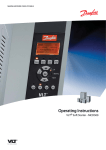
Ramsey Electronics Model No.
STC1
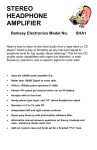
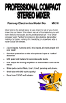
Now you can give your home stereo transmitter all of the features
found in a professional radio station! Control and prevent
overmodulation, interference from high frequency signals such as
TVs and older CD players, and “sweeten” the mix with Bass,
Presence, and Brilliance. A perfect companion for the FM10A and
the FM25 or any other FM radio transmitter!
•
Gives your station that professional sound with real “Punch!”
•
Ideal companion for FM10A and FM25
•
Requires any DC voltage from 9 to 12VDC
•
Uses line levels from CD players, tape decks, mixers etc.
•
Bass, Presence, and Brilliance controls
•
Dynamic range limiter to prevent overmodulation.
•
15kHz 8th order butterworth low pass filters on each output to
prevent high frequency interference with the stereo carrier.
•
Clear, concise assembly instructions lead you to a finished product
that works FIRST time!
•
Add our case and knob set for a finished ‘Pro’ look. Cases match all
Ramsey products.
STC1• 1
RAMSEY TRANSMITTER KITS
• FM10A, FM25B FM Stereo Transmitters
• TV6 Television Transmitter
• FM100B Super Pro FM Stereo Transmitter
RAMSEY RECEIVER KITS
• FR1 FM Broadcast Receiver
• AR1 Aircraft Band Receiver
• SR2 Short-wave Receiver
• AA7 Active Antenna
• SC1 Short-wave Converter
RAMSEY HOBBY KITS
• SP1 Speakerphone
• MD3 Microwave Motion Detector
• PH14,15,16 Peak hold Meters, great for VU meters!
• LC1 Inductance-Capacitance Meter
• TFM3 Tri-Field Meter
• ECG1 Heart Monitor
• LABC1 Lead Acid Battery Charger
RAMSEY AMATEUR RADIO KITS
• DDF1 Doppler Direction Finder
• HR Series HF All Mode Receivers
• QRP Series HF CW Transmitters
• VLF1 Low Bander Low Frequency SWL Converter
• CPO3 Code Practice Oscillator
• QRP Power Amplifiers
RAMSEY MINI-KITS
Many other kits are available for hobby, school, Scouts and just plain FUN. New
kits are always under development. Write or call for our free Ramsey catalog.
STC1 STEREO TRANSMITTER COMPANION INSTRUCTION MANUAL
Ramsey Electronics publication No. MSTC1 Revision 1.3
First printing: Jan. 1996 MRW
COPYRIGHT 1996 by Ramsey Electronics, Inc. 590 Fishers Station Drive, Victor, New York
14564. All rights reserved. No portion of this publication may be copied or duplicated without the
written permission of Ramsey Electronics, Inc. Printed in the United States of America.
STC1• 2
Ramsey Publication No. STC1
Price $5.00
KIT ASSEMBLY
AND INSTRUCTION MANUAL FOR
STC1 STEREO TRANSMITTER
COMPANION
TABLE OF CONTENTS
Introduction .....................................4
How Does It Work? .........................5
Learn As You Build .........................7
Parts List .........................................8
Construction..................................10
Schematic Diagram ......................14
Setup And Testing ........................21
Using The STC1 ...........................22
Parts Layout Diagram ...................24
Parts Value Diagram.....................25
Troubleshooting ............................26
RAMSEY ELECTRONICS, INC.
590 Fishers Station Drive
Victor, New York 14564
Phone (585) 924-4560
Fax (585) 924-4555
STC1• 3
INTRODUCTION TO THE STEREO TRANSMITTER COMPANION
Knowing how troublesome different audio sources can be when trying to
transmit them over the air, we have come up with a product that will eliminate
many of the problems. This kit allows the FM10A and the FM25 stereo
transmitters to have the same quality audio and transmission that the
professional radio stations have. The STC1 has many of the same features the
professional sound processors have, and will be sure to please your listening
audience when used with your home brew transmitter.
If you have experienced a steady whine while trying to transmit a television
signal or audio from an older CD player, this kit will help to reduce the problem.
The cause of this problem is the horizontal sweep frequency in a television, or
the 44kHz sampling frequency of the CD player mixing with the 38kHz stereo
carrier. What you are hearing is the sum and the difference frequencies that are
the result of the mixing process. The same occurs with high frequency audio
such as cymbals and when someone says the letter ‘s’.
To help control this problem, this kit incorporates a 16kHz 8th order Butterworth
low-pass filter. This helps to eliminate interference with high frequencies, such
as cheap CD players and other high frequency interference. Some of you may
ask what 8th order means? Well, put simply it means a steep cutoff curve
above 16kHz. The more orders in a filter, the greater the slope of the cutoff
curve. Butterworth is the name given to the description of the curve’s shape. A
Butterworth curve means there are no dips or peaks in the audio response
before the cutoff point’s frequency. This means there is no “coloration” added to
the audio being processed in the circuit.
To prevent overmodulation in your transmitter, this kit incorporates a soft
limiter. This limiter prevents the audio from going over a certain set level. Since
the audio is limited, so will be your modulation. There are indicator LEDs
included so that when the limiter is activated, you will know. When an audio
signal is limited, it introduces distortion into the audio causing the sound to
become rather distorted. The idea is to run your audio just under the limiting
level so that the LEDs blink very rarely. It also is a good way to keep all of your
audio levels close to the same for sound volume consistency.
To add a little more functionality to the STC1, and make it difficult for the
engineer to stuff all the parts on a small, single-sided board with a very few
jumpers, a set of tone controls were added in. This allows you to compensate
for a lack or surplus of bass, treble or midrange before the sound is transmitted.
Some people don’t like a nice flat response in their sound, they like the bass
turned up to give a nice full sound to their listeners. Needless to say these tone
controls allow you to custom tailor your sound to your own tastes.
STC1• 4
HOW DOES IT WORK?
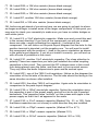
To help you understand where we are in the circuit you will want to look at the
circuit diagram in the center of the manual. We will work from the input of the
left channel to the output of the left channel. We don’t need to look at the right
channel since it is identical to the left half.
The audio signal coming into J1 is a line level signal at about 1 volt peak-topeak, which is a 0dB line level signal (standard). The audio level is cut in half
by resistors R63 and R28. This is necessary due to the lower voltages supplied
in the circuit. This keeps the signal level well inside the operating range of the
opamps later in the circuit to prevent distortion.
The signal then enters into U1:A and surrounding capacitors and resistors. This
is an active low pass filter to prevent any signals from outside the audio range
from entering into our circuit. This keeps high frequency signals from interfering
with our special filters later in the circuit.
The low pass filter output is then fed into what appears to be three feedback
loops in an opamp circuit. Each branch is a different type of filter. One for low
pass, one for midrange, and one for high pass. Yes, you have it, it’s the tone
controls for the left channel of the circuit. This arrangement allows us to boost
or cut frequencies from +/-12dB in three bands.
The output of our tone controls are then fed to the limiter circuit. This is where a
little magic comes into play when you see the two diodes in the feedback path
of the opamp. As you may know, diodes only conduct in one direction, but what
you may not know is that it takes about .5 to .7 volts to begin to conduct in the
forward direction. This is called the forward voltage drop of the diode. This .7
volt drop is used as our limiting voltage reference.
During signal levels under .5 volts peak-to-peak on the output pin 1 of U2:A ,
U2:A acts like a simple inverting amplifier with its gain controlled by R23, R18,
and the feedback resistor of R15. For example if we had R23 set at 7.8K ohms,
the gain of the circuit would be -1 in these signal conditions. The change comes
with signal levels over .5 volts. The diodes D1 and D2 begin to conduct on either positive or negative going signals since they are connected in opposite directions. This allows R51 to come into the gain equation. When the diodes are
on the gain lowers dramatically. In this case the gain goes to less than -.1. Now
the gain is 1/10 of what it used to be, and it prevents the output of this stage
from going much over .7 volts peak-to-peak.
The output of this limiter stage is then fed to two different stages, one of which
is the clip detector. This clip detector is set to detect any signal over .6 volts
peak-to-peak at the output of the limiter, which is where significant sound distortion begins. D6, C4, R55, and R58 make up a simple peak hold circuit by
rectifying the AC audio output of the limiter into a DC level related to volume.
STC1• 5
When this voltage on pin 5 of U2:B goes higher than 5 volts of the supply on pin
6 of U2:B, the output of U2:B goes high, thus lighting the LED clip indicator.
The other part of the signal goes to U3, a switched capacitor lowpass 8th order
Butterworth filter. These filters are really neat since they don’t need any high
accuracy frequency dependent parts, and don’t require pancakes. All that is
needed is a good steady TTL clock signal to set the cutoff frequency. Internally
these chips have a divide by 100 cutoff in relation to the clock frequency, so to
get a cutoff frequency of 15KHz, we needed a clock frequency of 1.5MHz.
Since 555 timers don’t like to run at this speed, a stable source was needed
that was better than a CMOS oscillator. Well, a little overkill never hurt anyone,
so now there is a crystal oscillator running at 6MHz, and divided by 4 by U6:A
and U6:B to give us 1.5MHz. Now we have a cutoff frequency right at 15kHz
with very little drifting in frequency.
There is also an internal opamp inside of U3, which allows us to filter the clock
frequency out of the audio signal before going out to J2 and then on to your
transmitter. R14,16,17, C9, and C16 are the parts included for this filter (Notice
similar part values around U1:A)
Well, that about sums it all up. Now we will get on to the fun stuff, and make
ourselves a really great kit that we understand!
NOTE TO NEWCOMERS: If you are a first time kit builder you may find this
manual easier to understand than you may have expected. Each part in the kit
is checked off as you go, while a detailed description of each part is given. If
you follow each step in the manual in order, and practice good soldering and kit
building skills, the kit is next to fail-safe. If a problem does occur, the manual
will lead you through step by step in the troubleshooting guide until you find the
problem and are able to correct it.
STC1• 6
RAMSEY “LEARN-AS-YOU-BUILD” ASSEMBLY STRATEGY
Be sure to read through all of the steps, and check the boxes as you go to be
sure you didn't miss any important steps. Although you may be in a hurry to see
results, before you switch on the power check all wiring and capacitors for
proper orientation. Also check the board for any possible solder shorts, and/or
cold solder joints. All of these mistakes could have detrimental effects on your
kit - not to mention your ego!
Kit building tips:
Use a good soldering technique - let your soldering iron tip gently heat the
traces to which you are soldering, heating both wires and pads simultaneously.
Apply the solder on the iron and the pad when the pad is hot enough to melt the
solder. The finished joint should look like a drop of water on paper, somewhat
soaked in.
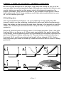
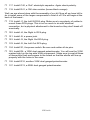
Mount all electrical parts on the top side of the board provided. This is the side
that has little or no traces on it. When parts are installed, the part is placed flat
to the board, and the leads are bent on the backside of the board to prevent the
part from falling out before soldering (1). The part is then soldered securely to
the board (2-4), and the remaining lead length is then clipped off (5). Notice
how the solder joint looks on close up, clean and smooth with no holes or sharp
points (6).
STC1• 7
RAMSEY STC1 PARTS LIST
Semiconductors
❒ 2 LF347 Quad Op-Amps (U1,2)
❒ 1 74HC74 Dual type ‘D’ flip-flops (U6)
❒ 2 MAX291 8th order Butterworth Switched Capacitor Filters (U3,5)
❒ 6 1N4148 small signal diodes (small glass body with black stripe)
(D1,2,3,4,6,8)
❒ 1 4.9 to 5.1 volt zener diode (small black or grey body with stripe on one
end) (D5)
❒ 2 7805 three terminal regulators (marked 78L05) (VR1,2)
❒ 1 2N3904 NPN transistor (Q1)
❒ 2 LEDs (D7,9)
Resistors
❒ 1 100 ohm resistor (brown-black-brown) (R47)
❒ 5 270 ohm resistors (red-violet-brown) (R40,56,57,60,61)
❒ 8 1K ohm resistors (brown-black-red) (R19,43,44,46,48,50,51,54)
❒ 4 1.8K ohm resistors (brown-gray-red) (R11,12,36,37)
❒ 2 2.2K ohm resistors (red-red-red) (R18,27)
❒ 4 3.3K ohm resistors (orange-orange-red) (R8,9,31,32)
❒ 6 4.7K ohm resistors (yellow-violet-red) (R28,35,38,39,63,64)
❒ 12 10K ohm resistors (brown-black-orange) (R4,5,7,15,24,25,26,30,41,
42,52,53)
❒ 8 15K ohm resistors (brown-green-orange) (R1,2,14,17,20,21,29,34)
❒ 6 47K ohm resistors (yellow-violet-orange) (R3,16,22,33,55,59)
❒ 1 100K ohm resistor (brown-black-yellow) (R45)
❒ 2 4.7M ohm resistors (yellow-violet-green) (R58,62)
STC1• 8
Capacitors
❒ 5 100pF ceramic capacitors (marked 100, or 101) (C1,9,18,27,45)
❒ 1 470pF ceramic capacitor (marked 470 or 471) (C46)
❒ 4 .001uF ceramic capacitors (marked .001, 102, or 1n) (C6,16,25,32)
❒ 4 .0047uF or .005uF ceramic capacitors (marked .0047, 472, .005, or 502)
(C7,10,29,34)
❒ 2 .01uF ceramic capacitors (marked .01, 103, or 10n) (C38,42)
❒ 2 .022uF or .02uF ceramic capacitors (marked .022, 223, .02 or 203)
(C8,C31)
❒ 2 .047uF or .05uF ceramic capacitors (marked .047, 473, .05 or 503)
(C2,20)
❒ 1 .1uF ceramic capacitors (marked .1, 104, or 100n) (C44)
❒ 15 10uF electrolytic capacitors (marked 10uF) (C3,4,5,11,12,13,21,23,
26,28,35,37,40,41,43)
❒ 2 100uF electrolytic capacitors (marked 100uF) (C36,39)
Miscellaneous
❒ 1 DPDT power switch (S1)
❒ 1 Power jack (J5)
❒ 4 RCA jacks (J1,2,3,4)
❒ 2 100K trimmer pots (orange tops marked 104) (R23,49)
❒ 2 100K dual ganged potentiometers (R6,10)
❒ 1 500K dual ganged potentiometers (R13)
❒ 1 6.00MHz crystal (marked 6.000) (X1)
❒ 1 12” piece of hookup wire.
STC1• 9
CONSTRUCTION OF THE STEREO TRANSMITTER COMPANION
Sort out all of your parts to begin with, making sure you have all of the parts
required. You can use old egg cartons to hold various parts to make them
easier to find. We will begin building the kit from the back end of the board
where all the jacks will eventually be placed. Make sure to mount parts on the
correct side! You will want to use the parts layout diagram to assist you in
finding where the parts go.
This is a fairly tightly packed in board so we will be installing some of the lower
profile parts before we begin on the higher profile components like capacitors
and regulators. Have some patience and take the steps in order and we will
have a working kit in the end.
For each part, our word "Install" always means these steps:
1. Pick the correct part value to start with.
2. Insert it into the correct PC board location.
3. Orient it correctly, follow the PC board drawing and the written
directions for all parts - especially when there's a right way and a wrong
way to solder it in. (Diode bands, electrolytic capacitor polarity, transistor
shapes, dotted or notched ends of IC's, and so forth.)
4. Solder all connections unless directed otherwise. Use enough heat and
solder flow for clean, shiny, completed connections.
❒
1. Orient the board in the same direction as the parts layout diagram.
❒
2. Install R63, a 4.7K ohm resistor (yellow-violet-red).
Note that this resistor and many others are installed in a
“stand up” position. Keep the component nice and
vertical for neatness, but the lead lengths as short as
possible for proper operation. Notice the relationship of
the mounting of the part and the way it is shown on the parts layout
diagram.
❒
3. Install R28, another 4.7K ohm resistor (yellow-violet-red).
❒
4. Install R35, a 4.7K ohm resistor (yellow-violet-red).
❒
5. Install R64, a 4.7K ohm resistor (yellow-violet-red).
❒
6. Install R38, yet another 4.7K ohm resistor (yellow-violet-red).
❒
7. Install R39, even another 4.7K ohm resistor (yellow-violet-red).
❒
8. Install R53, a 10K ohm resistor (brown-black-orange).
❒
9. Install D5, the 4.7 or 5.1 volt zener diode. The easiest way of identifying
this diode is by comparing it to the rest of the diodes in your kit. This is the
only one of its kind, so it will look quite a bit different than the 1N4148 type
STC1• 10
diodes in the kit. Since the appearance of this part is likely to change as we
order these parts in the factory, this is how we will need to identify them.
Make sure the banded end of the diode is installed in the same direction as
shown in the parts layout diagram.
❒
10. Using a piece of scrap component lead from the parts you have
installed earlier, install JMP3, a jumper. Jumpers act as “bridges” over other
circuit paths on the PC board, allowing for a better routing of the board.
❒
11. Again using a piece of scrap component lead, install JMP1, another
jumper.
❒
12. Install R47, a 100 ohm resistor (brown-black-brown).
❒
13. Install the 74HC74 dual type D flip flop. Be careful to observe the
correct orientation of this device before you begin soldering. Notice the
notch indicated in your parts layout diagram. This notch corresponds to pin
1 of the IC, and your part should be installed in the same orientation as
shown. Pin 1 may also be indicated by a white dot on the IC or a dimple.
Make sure all 14 pins are through the PC board before soldering.
❒
14. Install R21, a 15K ohm resistor (brown-green-orange).
❒
15. Install R2, another 15K ohm resistor (brown-green-orange).
❒
16. Install R1, a 15K ohm resistor (brown-green-orange).
❒
17. Install R3, a 47K ohm resistor (yellow-violet-orange).
❒
18. Install R20, a 15K ohm resistor (brown-green-orange).
❒
19. Install R22, a 47K ohm resistor (yellow-violet-orange).
❒
20. Install R48, a 1K ohm resistor (brown-black-red).
❒
21. Install R45, a 100K ohm resistor (brown-black-yellow).
❒
22. Install R40, a 270 ohm resistor (red-violet-brown).
❒
23. Install R43, a 1K ohm resistor (brown-black-red).
❒
24. Install R46, another 1K ohm resistor (brown-black-red).
❒
25. Using a scrap piece of component lead, install JMP4, a jumper.
❒
26. Install U1, a LM347 quad op-amp. Make sure all 14 pins are through the
board before soldering, and that the notch or dot indicating pin one of the IC
is in the same orientation as shown on the parts layout diagram. Double
check your work when you are done.
❒
27. Install R50, a 1K ohm resistor (brown-black-red).
STC1• 11
❒
28. Install R25, a 10K ohm resistor (brown-black-orange).
❒
29. Install R26, a 10K ohm resistor (brown-black-orange).
❒
30. Install R30, a 10K ohm resistor (brown-black-orange).
❒
31. Install R7, another 10K ohm resistor (brown-black-orange).
❒
32. Install R5, a 10K ohm resistor (brown-black-orange).
OK, before we get ahead of ourselves here, we are going to go back to where
we began and begin to install some of the larger components. At this point you
may want to check your assembly to make sure you have no solder bridges or
cold solder joints.
❒
33. Install C3, a 10uF electrolytic capacitor. Make sure and mount this part
in the correct direction! If you look at the component you will see a stripe
down one side, usually indicating the negative (-) terminal of the
component. You will notice on the parts layout diagram that the hole for the
positive terminal is denoted, not the negative one. You will want to install
this component with the positive (+) lead in the same orientation as shown
in the parts layout diagram. If you do not install it correctly, you will end up
with all sorts of problems in the circuit.
❒
34. Install C21, another 10uF electrolytic capacitor. Pay close attention to
polarity! These two capacitors you have just installed are called coupling
capacitors in this circuit. They prevent the DC voltages seen in this circuit
from being placed upon the jacks, and then sent to your musical source.
They only allow the audio frequencies to pass and be worked upon.
❒
35. Install VR1, one of the 7805 5 volt regulators. Notice on the diagram the
orientation of the flat side of the device. The flat side should be facing in the
same direction as shown after installed.
❒
35. Install VR2, the other 7805 5 volt regulator. Again note its orientation in
comparison to the parts layout diagram.
❒
36. Install C39, a 100uF electrolytic capacitor. Notice the orientation since
this capacitor is part of the power supply and will not do its job if inserted
backwards. This capacitor helps “smooth” out the noises and ripple in the
power supply so that it isn’t as apparent in the audio.
❒
37. Install C42, a .01uF ceramic capacitor (Marked 10n, .01, or 103). Note
that these capacitors are not choosy in what direction they are installed.
❒
38. Install C46, a 470pF ceramic capacitor (Marked 470 or 471).
❒
39. Install C45, a 100pF ceramic capacitor (Marked 101).
❒
40. Install C25, a .001uF ceramic capacitor (Marked .001 or 102).
STC1• 12
❒
41. Install C6, a .001uF ceramic capacitor (Marked .001 or 102).
❒
42. Install X1, the 6.00MHz crystal (Metal can marked 6.000).
❒
43. Install Q1, the 2N3904 type small signal transistor. Observe the correct
orientation of the flat side.
You have just completed the 6MHz oscillator section of the PC board. This
circuit is called a Colpitts oscillator, and is very good at producing the voltage
levels and frequency we need to see at the inputs of U6, the CMOS type ‘D’ flipflop. Also notice that this circuit’s accuracy is not important when it comes to
filtering audio, and can be off by as much as 10% with no problems at all, but
this oscillator will run at better than .01% accuracy without even aligning it!
Now we will begin installing the sound processing circuitry which allows us to
control bass, midrange, and highs.
❒
44. Install C1, a 100pF ceramic capacitor (Marked 100 or 101).
❒
45. Install C18, another 100pF ceramic capacitor (Marked 100 or 101).
❒
46. Install C23, a 10uF electrolytic capacitor. Pay close attention to polarity!
❒
47. Install C38, a .01uF ceramic capacitor (Marked .01, 10n, or 103).
❒
48. Install C20, a .047uF or .05uF ceramic capacitor (Marked .047,
473, .05, or 503).
❒
49. Install C5, a 10uF electrolytic capacitor. Polarity!
❒
50. Install C36, a 100uF electrolytic capacitor. Again pay close attention to
polarity. This is another capacitor that helps to “smooth” out the power
supply.
❒
51. Install C2, a .047uF or .05uF ceramic capacitor (marked 473, .047, .05,
or 503).
❒
52. Install R4, a 10K ohm resistor (brown-black-orange).
❒
53. Install R9, a 3.3K ohm resistor (orange-orange-red).
❒
54. Install R32, another 3.3K ohm resistor (orange-orange-red).
❒
55. Install C7, a .0047uF or .005uF ceramic capacitor (marked .0047,
472, .005, or 502).
❒
56. Install C8, a .022uF or .02uF ceramic capacitor (marked .022 or 223).
❒
57. Install C29, a .0047uF or .005uF ceramic capacitor (marked .0047,
472, .005, or 502).
STC1• 13
STC1• 14
STC1• 15
❒
58. Install C31, a .022uF ceramic capacitor (marked .022 or 223).
❒
59. Install R8, a 3.3K ohm resistor (orange-orange-red).
❒
60. Install R11, a 1.8K ohm resistor (brown-gray-red).
❒
61. Install R12, a 1.8K ohm resistor (brown-gray-red).
❒
62. Install C10, a .0047uF or .005uF ceramic capacitor (marked
472, .0047, .005, or 502).
❒
63. Install R37, a 1.8K ohm resistor (brown-gray-red).
Whew! I thought we were never going to quit installing parts! Now would be a
great time to go grab a soda or whatever meets you palette, relax, and then
come back to check on errors. You may be amazed at all the mistakes that the
gremlins caused you to make during the install process. Check all of your
soldering for cold solder joints, solder bridges, and correct part installment
before continuing. Especially check your capacitors, many people get confused
when they see the positive pin on the parts layout diagram, but the negative
one is denoted on the part itself, and should not be installed in the same hole.
❒
64. Install C34, a .0047uF or .005uF ceramic capacitor (marked .0047,
472, .005, or 502).
❒
65. Install R31, a 3.3K ohm resistor (orange-orange-red).
❒
66. Install R36, a 1.8K ohm resistor (brown-gray-red).
❒
67. Install R51, a 1K ohm resistor (brown-black-red).
❒
68. Install D1, one of the 1N4148 type diodes (clear body with black stripe
on one end). Make sure that this part is installed in the correct way since it
only conducts in one direction. Notice the banded end and make sure it is
installed in the same direction as in the parts layout diagram.
❒
69. Install D2, another 1N4148 type diode (clear body with black stripe on
one end). Again note its orientation!
These previous two diodes are responsible for the limiting that occurs in our
limiting circuit of the left channel. The next diode is used in a peak hold circuit to
detect the signal level at where limiting occurs.
❒
70. Install D6, another 1N4148 type diode (clear body with black stripe on
one end). Orientation!
❒
71. Install R56, a 270 ohm resistor (red-violet-brown).
❒
72. Install R15, a 10K ohm resistor (brown-black-orange).
STC1• 16
❒
73. Install C13, a 10uF electrolytic capacitor. Again note proper orientation.
❒
74. Install R18, a 2.2K ohm resistor (red-red-red).
❒
75. Install R23, one of the 100K ohm trimmer potentiometers (orange top
marked 104). This trimmer allows us to adjust the output level of the STC1
where clipping begins.
❒
76. Install U2, the other LM347 quad op-amp. Make sure all 14 pins are
through the PC board before soldering it to the board. Also make sure the
part is installed in the correct orientation with the notch, hole, or dot indicating
pin one of the IC on the parts layout.
❒
77. Install D3, a 1N4148 type diode. Pay close attention to orientation of the
striped end of the diode!
❒
78. Install D4, another 1N4148 type diode. Again check orientation as it is
opposite that of D3.
❒
79. Install D8, the last 1N4148 type diode. Orientation!
❒
80. Install R27, a 2.2K ohm resistor (red-red-red).
❒
81. Install C26, a 10uF electrolytic capacitor. Pay close attention to
orientation again!
❒
82. Install C35, yet another 10uF electrolytic capacitor. Polarity!
❒
83. Install R49, a 100K ohm trimmer potentiometer (orange top marked 104).
❒
84. Install R24, a 10K ohm resistor (brown-black-orange).
❒
85. Install R54, a 1K ohm resistor (brown-black-red).
❒
86. Install R60, a 270 ohm resistor (red-violet-brown).
❒
87. Install C12, a 10uF electrolytic capacitor. Orientation!
❒
88. Install R61, a 270 ohm resistor (red-violet-brown).
❒
89. Install R57, another 270 ohm resistor (red-violet-brown).
❒
90. Install R55, a 47K ohm resistor (yellow-violet-orange).
❒
91. Install C4, a 10uF electrolytic capacitor. Again check your orientation so
that the positive marked hole is opposite the negative marked capacitor.
❒
92. Install R58, a 4.7M ohm resistor (yellow-violet-green).
❒
93. Install C28, a 10uF electrolytic. Orientation!
❒
94. Install R59, a 47K ohm resistor (yellow-violet-orange).
STC1• 17
❒
95. Install R62, a 4.7M ohm resistor (yellow-violet-green).
Guess what? we have just completed the limiter circuitry and the peak hold
detectors that let us know when clipping occurs. Now we are on to complete the
remainder of the kit, the 8th order switched capacitor filters.
❒
96. Install R19, a 1K ohm resistor (brown-black-red).
❒
97. Install R44, a 1K ohm resistor (brown-black-red).
❒
98. Install R52, a 10K ohm resistor (brown-black-orange).
❒
99. Install C43, a 10uF electrolytic. In case you forgot, check polarity!
❒
100. Install C11, another 10uF electrolytic capacitor.
❒
101. Install U5, one of the MAX291 8 pin ICs. Make sure all 8 pins are
through the PC board before soldering, and that the part is correctly
oriented.
❒
102. Install C44, a .1uF ceramic capacitor (marked 104 or .1).
❒
103. Install C27, a 100pF ceramic capacitor (marked 101).
❒
104. Install R34, a 15K ohm resistor (brown-green-orange).
❒
105. Install R33, a 47K ohm resistor (yellow-violet-orange).
❒
106. Install R29, a 15K ohm resistor (brown-green-orange).
❒
107 Install C32, a .001uF ceramic capacitor (marked .001 or 102).
❒
108. Install C41, a 10uF electrolytic capacitor. Check the direction of your
installation!
❒
109. Install U3, the other MAX291. Make sure all eight pins are through the
board before soldering, and that the part is installed in the correct direction
in relation to the parts layout diagram.
❒
110. Install C9, a 100pF ceramic capacitor (marked 101).
❒
111. Install R14, a 15K ohm resistor (brown-green-orange).
❒
112. Install C37, a 10uF electrolytic capacitor. Polarity!
❒
113. Install R16, a 47K ohm resistor (yellow-violet-orange).
❒
114. Install R17, a 15K ohm resistor (brown-green-orange).
❒
115. Install R42, a 10K ohm resistor (brown-black-orange).
❒
116. Install C16, a .001uF ceramic capacitor (marked 102 or .001).
STC1• 18
❒
117. Install C40, a 10uF electrolytic capacitor. Again check polarity.
❒
118. Install R41, a 10K ohm resistor (brown-black-orange).
Well, we are almost done with the assembly of our kit. Now all we have left to
do is install some of the larger components to finish it off. We will begin at the
back of the board...
❒
119. Install J1, the Left IN RCA plug. Make sure to use plenty of solder to
mount these RCA plugs. This is not so much to do with electrical
connection, but a physical attachment to the board so they don't break off
eventually.
❒
120. Install J4, the Right In RCA plug.
❒
121. Install J5, a power jack.
❒
122. Install J3, the Right Out RCA plug.
❒
123. Install J2, the Left Out RCA plug.
❒
124. Install S1, the power switch. Be sure and solder all six pins.
❒
125. Install R6, a 100K dual ganged potentiometer. You will see the 100K
marked right on the top side of the component. Make sure to seat all three
of these pots flush and square to the board so that the shafts will line up
properly with the holes in the case.
❒
126. Install R10, another 100K dual ganged potentiometer.
❒
127. Install R13, a 500K dual ganged potentiometer.
STC1• 19
Wow! we are finally finished installing parts into the board. You may of noticed
that you have two LEDs left over. This is where you get to make a choice of
how and where you want to mount these. If you have bought the case with this
kit, follow the following directions so that the LEDs line up with the case front
panel. Otherwise you can put them anywhere you want, just make sure that
they are installed in the correct direction so they will light. LEDs are Light
Emitting Diodes, and like diodes, they only conduct in one direction. In the case
of an LED, they give off light as they conduct.
❒
a. Locate the supplied hook-up wire and cut it in half.
❒
b. Strip both ends of each wire back 1/4”.
❒
b. Solder one wire into the hole marked D7 for the left LED.
❒
c. Solder the other wire into the hole marked D9 for the right LED.
❒
d. Install the shorter end of one of the LEDs into the hole near the switch
marked D9. The shorter lead is the cathode connection of the LED and if
you have cut the leads, it is also the larger base inside the LED. To do this,
bend the cathode lead at a 90 degree angle from the LED. Stand the center
of the LED up about .7”-.75” from the surface of the PC board as shown
above.
❒
e. Install the cathode end of the other LED into the hole marked D7 using
the same procedure.
❒
f. Connect the D9 wire to the free end of D9.
❒
g. Connect the D7 wire to the free end of D7.
❒
h. All done!
STC1• 20
SETUP AND TESTING:
You can test your STC1 by simply hooking it up and trying it or by using test
equipment.
For a test with testing equipment you will need:
❍ Audio Signal Generator
❍ DMM or oscilloscope
❍ 9 to 15 volt DC power supply.
All we want to do here is verify that our assembly has been done correctly, and
calibrate the unit for proper operation. Before we begin, make sure that all
controls are set in the center position, all capacitors are mounted in the correct
direction, and the board has been checked at least twice for any errors.
❒
1. Check Pin 4 of U1 for +10 volts DC.
❒
2. Check Pin 10 of U1 for +5 volts DC.
❒
3. Connect your oscilloscope probe to pin 9 of U6. Verify that there is a
good clean square wave at 1.5MHz. This means the switched capacitor
filters should be operating, as well as the oscillator and dividers.
❒
4. Connect the signal generator to the left channel input, J1. Set it at 1kHz.
❒
5. Using the DMM or oscilloscope, set the input voltage to about 1 volt
peak.
❒
6. Adjust R23 until the left clip LED barely lights.
❒
7. Check the output voltage of the left channel at J2, it should be
between .5 and 1 volts peak.
❒
8. Perform the same for the right channel, using R49 to adjust the LED.
❒
9. Any troubles? Check out the troubleshooting guide for help in finding a
problem.
STC1• 21
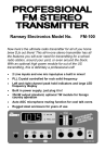
USING THE STC1:
The STC1 is simply a sound processor. It is installed in series to process the
audio right before it goes to the transmitter itself. No more processing should be
done on the audio between the STC1 and the transmitter, otherwise it throws
off the clipping settings. If you have an equalizer connected to your transmission setup, connect it before the STC1.
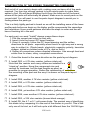
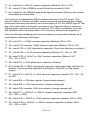
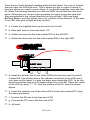
An example setup is shown to give you an idea of a setup that we have here at
Ramsey. Any mixer can be in place of the MX10, but the MX10 gives you all
the goodies you need for a good solid radio show such as smooth panning,
LED peak hold bargraph, and low noise. In specific, it was designed for use
with stereo transmitters.
To get the right sound levels and proper deviation out of the stereo transmitter,
you will most likely need to turn up the gain controls in the transmitter itself. The
reason for this is the non-clipped audio on the output of the STC1 is actually
about one-half the voltage level of actual line level (about .5 volts peak-topeak). This level is where the good clean sound is available. The easiest way to
do this is just compare your sound level to that of adjacent radio stations on a
good FM receiver. Just adjust the levels until they sound about the same.
The most fun part of this kit is custom tailoring your sound to you own specific
desires. The Bass, Presence, and Brilliance controls allow you to do this with a
great range of flexibility. For you hard rocker types, you will want to turn the
Presence back a bit, then crank the Bass and the Brilliance to emphasize the
drums and guitar. For you country music buffs, you will want to turn up the
presence to emphasize the vocals. For soft rock you may want to turn back the
Brilliance to give the music a more warm and cozy sound. Lets not forget the
R&B and RAPP, this is where the Bass control comes in handy.
When you adjust the sound to your tastes, and have turned up any of the controls on the STC1, you may want to consider turning down the gain on the clip
controls of the STC1. Since you are increasing the gain in a particular band of
audio frequencies, this band will be more likely to cause clipping distortion due
to the higher audio levels produced. The LEDs on the front panel should be a
good indication of when this occurs, so just turn back the gain until they don’t
blink anymore.
Enjoy your new addition to your micropower radio station, happy transmitting!
STC1• 22
EXAMPLE HOOKUP
STC1• 23
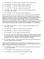
PARTS LAYOUT DIAGRAM
STC1• 24
PARTS VALUE DIAGRAM
STC1• 25
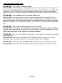
TROUBLESHOOTING TIPS
PROBLEM: No 1.5MHz oscillator signal.
SOLUTION: First check your testing procedures to make sure your scope is on
the correct settings and that you have the power on the STC-1. If so, check the
collector of Q1 for 6MHz. If you do not have signal there, check surrounding
parts for shorts or cold solder joints. Otherwise, check U6 for power on it’s pins,.
PROBLEM: One channel is out, the other works OK.
SOLUTION: You may have a short or open somewhere through the circuit.
This is where an oscilloscope would come in handy. Insert an audio signal into
both of the inputs, then trace through the circuit with the probe. When you have
gazinda (input) with no gazada (output), you will then know where the problem
lies.
PROBLEM: The sound is distorted before the LEDs light.
SOLUTION: Back down the settings on the clip level adjusters. High frequency
sounds aren’t registered as quickly on the indicators as is low frequencies. The
LEDs should almost never light on the proper settings.
PROBLEM: Any one of the LEDs never lights, even when turning the clip adjust
all the way up.
SOLUTION: Check the orientation of the installed LED to make sure it was
installed in the correct direction. Try reversing it and see if it lights.
PROBLEM: I just can’t get the #@%*$#&! thing to work! It’s Ramsey’s fault!
SOLUTION: Read the warranty information towards the back of this manual.
STC1• 26
The Ramsey Kit Warranty
Please read carefully BEFORE calling or writing in about your kit. Most problems can be
solved without contacting the factory.
Notice that this is not a "fine print" warranty. We want you to understand your rights and ours too!
All Ramsey kits will work if assembled properly. The very fact that your kit includes this new manual
is your assurance that a team of knowledgeable people have field-tested several "copies" of this kit
straight from the Ramsey inventory. If you need help, please read through your manual carefully. All
information required to properly build and test your kit is contained within the pages!
1. DEFECTIVE PARTS: It's always easy to blame a part for a problem in your kit, Before you conclude that a part may be bad, thoroughly check your work. Today's semiconductors and passive
components have reached incredibly high reliability levels, and it’s sad to say that our human construction skills have not! But on rare occasions a sour component can slip through. All our kit parts
carry the Ramsey Electronics Warranty that they are free from defects for a full ninety (90) days
from the date of purchase. Defective parts will be replaced promptly at our expense. If you suspect
any part to be defective, please mail it to our factory for testing and replacement. Please send only
the defective part(s), not the entire kit. The part(s) MUST be returned to us in suitable condition for
testing. Please be aware that testing can usually determine if the part was truly defective or damaged by assembly or usage. Don't be afraid of telling us that you 'blew-it', we're all human and in
most cases, replacement parts are very reasonably priced.
2. MISSING PARTS: Before assuming a part value is incorrect, check the parts listing carefully to
see if it is a critical value such as a specific coil or IC, or whether a RANGE of values is suitable
(such as "100 to 500 uF"). Often times, common sense will solve a mysterious missing part problem. If you're missing five 10K ohm resistors and received five extra 1K resistors, you can pretty
much be assured that the '1K ohm' resistors are actually the 'missing' 10 K parts ("Hum-m-m, I
guess the 'red' band really does look orange!") Ramsey Electronics project kits are packed with
pride in the USA. If you believe we packed an incorrect part or omitted a part clearly indicated in
your assembly manual as supplied with the basic kit by Ramsey, please write or call us with information on the part you need and proof of kit purchase
3. FACTORY REPAIR OF ASSEMBLED KITS:
To qualify for Ramsey Electronics factory repair, kits MUST:
1. NOT be assembled with acid core solder or flux.
2. NOT be modified in any manner.
3. BE returned in fully-assembled form, not partially assembled.
4. BE accompanied by the proper repair fee. No repair will be undertaken until we have received
the MINIMUM repair fee (1 hour labor) of $50.00, or authorization to charge it to your credit
card account.
5. INCLUDE a description of the problem and legible return address. DO NOT send a separate letter; include all correspondence with the unit. Please do not include your own hardware
such as non-Ramsey cabinets, knobs, cables, external battery packs and the like. Ramsey
Electronics, Inc., reserves the right to refuse repair on ANY item in which we find excessive
problems or damage due to construction methods. To assist customers in such situations,
Ramsey Electronics, Inc., reserves the right to solve their needs on a case-by-case basis.
The repair is $50.00 per hour, regardless of the cost of the kit. Please understand that our technicians are not volunteers and that set-up, testing, diagnosis, repair and repacking and paperwork
can take nearly an hour of paid employee time on even a simple kit. Of course, if we find that a part
was defective in manufacture, there will be no charge to repair your kit (But please realize that our
technicians know the difference between a defective part and parts burned out or damaged through
improper use or assembly).
4. REFUNDS: You are given ten (10) days to examine our products. If you are not satisfied, you
may return your unassembled kit with all the parts and instructions and proof of purchase to the factory for a full refund. The return package should be packed securely. Insurance is recommended.
Please do not cause needless delays, read all information carefully.
STC1• 27
STC1 Stereo Transmitter Companion
Quick Reference Page Guide
Introduction ..................................... 4
How Does It Work? ........................ 5
Learn As You Build ......................... 7
Parts List ........................................ 8
Construction ................................. 10
Schematic Diagram ...................... 14
Setup And Testing ........................ 21
Using The STC1 ........................... 22
Parts Layout Diagram ................... 24
Parts Value Diagram .................... 25
Troubleshooting ............................ 26
REQUIRED TOOLS
• Soldering Iron Ramsey WLC100
• Thin Rosin Core Solder Ramsey RTS12
• Needle Nose Pliers Ramsey MPP4 or
RTS05
• Small Diagonal Cutters Ramsey RTS04
<OR> Technician’s Tool Kit TK405
ADDITIONAL SUGGESTED ITEMS
• Holder for PC Board/Parts Ramsey HH3
• Desoldering Braid Ramsey RTS08
• Digital Multimeter Ramsey M133
Price: $5.00
Ramsey Publication No. MSTC1
Assembly and Instruction manual for:
RAMSEY MODEL NO. STC1
STEREO TRANSMITTER COMPANION KIT
RAMSEY ELECTRONICS, INC.
590 Fishers Station Drive
Victor, New York 14564
Phone (585) 924-4560
Fax (585) 924-4555
www.ramseykits.com
STC1• 28
TOTAL SOLDER POINTS
415
ESTIMATED ASSEMBLY
TIME
Beginner ............ 10 hrs
Intermediate......... 6 hrs
Advanced ............. 4.5 hrs