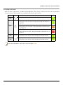
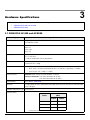
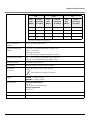
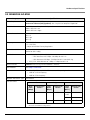
1
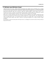
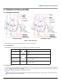
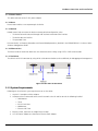
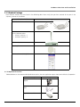
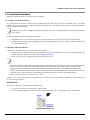
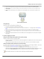
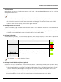
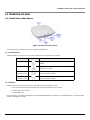
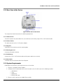
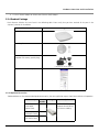
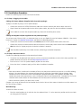
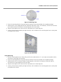
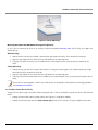
ORiNOCO® 802.11n Access Points
Hardware Installation Guide
Products Covered
ORiNOCO® AP-800
ORiNOCO® AP-8000
ORiNOCO® AP-8100
Copyright
© 2012 Proxim Wireless Corporation, Milpitas, CA. All rights reserved. Covered by one or more of the following U.S. patents: 5,231,634;
5,875,179; 6,006,090; 5,809,060; 6,075,812; 5,077,753. This guide and the software described herein are copyrighted with all rights reserved. No
part of this publication may be reproduced, transmitted, transcribed, stored in a retrieval system, or translated into any language in any form by any
means without the written permission of Proxim Wireless Corporation.
Trademarks
ORiNOCO® and the Proxim logo are the trademarks of Proxim Wireless Corporation. All other trademarks mentioned herein are the property of
their respective owners.
Disclaimer
Proxim reserves the right to revise this publication and to make changes in the content from time-to-time without obligation on the part of Proxim
to provide notification of such revision or change. Proxim may make improvements or changes in the product(s) described in this guide at any time.
When using these devices, basic safety precautions should always be followed to reduce the risk of fire, electric shock and injury to persons.
ORiNOCO® 802.11n Access Points - Hardware Installation Guide
Documentation Version: 4.1
P/N 765-00154, June 2012
ORiNOCO® 802.11n Access Points - Hardware Installation Guide
2
Contents
Preface . . . . . . . . . . . . . . . . . . . . . . . . . . . . . . . . . . . . . . . . . . . . . . . . . . . . . . . . . . . . . . . . . . . . . . . . . . .
1
4
Introduction . . . . . . . . . . . . . . . . . . . . . . . . . . . . . . . . . . . . . . . . . . . . . . . . . . . . . . . . . . . . . . . . . . . . . . . . . 6
About ORiNOCO® 802.11n Access Points . . . . . . . . . . . . . . . . . . . . . . . . . . . . . . . . . . . . . . . . . . . . . . . . . . . . . . . . . . . 6
Salient Features . . . . . . . . . . . . . . . . . . . . . . . . . . . . . . . . . . . . . . . . . . . . . . . . . . . . . . . . . . . . . . . . . . . . . . . . . . . . . . . 6
Multiple-Input-Multiple-Output . . . . . . . . . . . . . . . . . . . . . . . . . . . . . . . . . . . . . . . . . . . . . . . . . . . . . . . . . . . . . . . . . . . 7
2
Hardware Overview and Installation. . . . . . . . . . . . . . . . . . . . . . . . . . . . . . . . . . . . . . . . . . . . . . . . . . . . . 8
ORiNOCO® AP-800 and AP-8000 . . . . . . . . . . . . . . . . . . . . . . . . . . . . . . . . . . . . . . . . . . . . . . . . . . . . . . . . . . . . . . . . . 9
Hardware Overview . . . . . . . . . . . . . . . . . . . . . . . . . . . . . . . . . . . . . . . . . . . . . . . . . . . . . . . . . . . . . . . . . . . . . . . . . . . . . . . . . . . . 9
System Requirements . . . . . . . . . . . . . . . . . . . . . . . . . . . . . . . . . . . . . . . . . . . . . . . . . . . . . . . . . . . . . . . . . . . . . . . . . . . . . . . . . . 10
Product Package . . . . . . . . . . . . . . . . . . . . . . . . . . . . . . . . . . . . . . . . . . . . . . . . . . . . . . . . . . . . . . . . . . . . . . . . . . . . . . . . . . . . . . 11
Installation Procedure . . . . . . . . . . . . . . . . . . . . . . . . . . . . . . . . . . . . . . . . . . . . . . . . . . . . . . . . . . . . . . . . . . . . . . . . . . . . . . . . . . 12
ORiNOCO® AP-8100 . . . . . . . . . . . . . . . . . . . . . . . . . . . . . . . . . . . . . . . . . . . . . . . . . . . . . . . . . . . . . . . . . . . . . . . . . . 15
Front View of the Device. . . . . . . . . . . . . . . . . . . . . . . . . . . . . . . . . . . . . . . . . . . . . . . . . . . . . . . . . . . . . . . . . . . . . . . . . . . . . . . .
Rear View of the Device . . . . . . . . . . . . . . . . . . . . . . . . . . . . . . . . . . . . . . . . . . . . . . . . . . . . . . . . . . . . . . . . . . . . . . . . . . . . . . . .
System Requirements . . . . . . . . . . . . . . . . . . . . . . . . . . . . . . . . . . . . . . . . . . . . . . . . . . . . . . . . . . . . . . . . . . . . . . . . . . . . . . . . . .
Product Package . . . . . . . . . . . . . . . . . . . . . . . . . . . . . . . . . . . . . . . . . . . . . . . . . . . . . . . . . . . . . . . . . . . . . . . . . . . . . . . . . . . . . .
Installation Procedure . . . . . . . . . . . . . . . . . . . . . . . . . . . . . . . . . . . . . . . . . . . . . . . . . . . . . . . . . . . . . . . . . . . . . . . . . . . . . . . . . .
3
15
16
16
17
18
Hardware Specifications . . . . . . . . . . . . . . . . . . . . . . . . . . . . . . . . . . . . . . . . . . . . . . . . . . . . . . . . . . . . . . 22
ORiNOCO® AP-800 and AP-8000 . . . . . . . . . . . . . . . . . . . . . . . . . . . . . . . . . . . . . . . . . . . . . . . . . . . . . . . . . . . . . . . . 22
ORiNOCO® AP-8100 . . . . . . . . . . . . . . . . . . . . . . . . . . . . . . . . . . . . . . . . . . . . . . . . . . . . . . . . . . . . . . . . . . . . . . . . . . 24
A
Glossary and Abbreviations . . . . . . . . . . . . . . . . . . . . . . . . . . . . . . . . . . . . . . . . . . . . . . . . . . . . . . . . . . . 26
B
Statement of Warranty . . . . . . . . . . . . . . . . . . . . . . . . . . . . . . . . . . . . . . . . . . . . . . . . . . . . . . . . . . . . . . . 30
C
Technical Services and Support . . . . . . . . . . . . . . . . . . . . . . . . . . . . . . . . . . . . . . . . . . . . . . . . . . . . . . . . 32
ORiNOCO® 802.11n Access Points - Hardware Installation Guide
3
Preface
Preface
This chapter contains information on the following:
•
About this Guide
•
Products Covered
•
Audience
•
Prerequisites
•
Documentation Conventions
•
Related Documents
About this Guide
This guide gives a jump-start working knowledge on the ORiNOCO® 802.11n Access Points and details on their hardware
specifications and installation procedures.
Products Covered
Listed below are the products covered in this guide.
•
ORiNOCO® AP-800
•
ORiNOCO® AP-8000
•
ORiNOCO® AP-8100
Audience
The intended audience for this guide is the Network Administrator who installs and/or manages the device.
Prerequisites
The reader of this guide should have working knowledge of Wireless Networks, Local Area Networking (LAN) concepts,
Network Access Infrastructures and Client-Server Applications.
Documentation Conventions
Icon Representation
Name
Image
Description
Note
A special instruction that draws attention of a user.
Important
A note of significant importance that a user should be aware of.
Caution
A warning that cautions a user of the possible danger.
ORiNOCO® 802.11n Access Points - Hardware Installation Guide
4
Preface
Related Documents
For more information, please refer to the following additional documents that are available at proxim’s support site
http://support.proxim.com.
•
Quick Installation Guide (QIG) - A quick reference guide that provides essential information to install and configure
the device.
•
Software Management Guide - A guide that provides instructions on how to configure, manage and monitor the
device by using Web Interface.
•
Reference Guide - A guide that provides instructions on how to configure, manage and monitor the device by using
Command Line Interface.
•
Safety and Regulatory Compliance Guide - A guide that provides country specific safety and regulatory norms to
be followed while installing the devices.
: For regulatory information and latest product updates, visit our support site http://support.proxim.com.
ORiNOCO® 802.11n Access Points - Hardware Installation Guide
5
1
Introduction
This chapter contains information on the following:
•
About ORiNOCO® 802.11n Access Points
•
Salient Features
•
Multiple-Input-Multiple-Output
1.1 About ORiNOCO® 802.11n Access Points
Proxim’s ORiNOCO® 802.11n Access Point family comprises the following products, that are designed to deliver flexible,
scalable and reliable Data, Voice, and Video for small and medium Enterprise WLAN deployments.
Product(s)
Description
ORiNOCO® AP-800
An indoor 802.11n Access Point with dual-band, 3x3 MIMO
(Multiple Input and Multiple Output) single radio which operates
either in 2.4 or 5 GHz. This connectorized unit comes with 3
omni-directional antennas.
ORiNOCO® AP-8000
An indoor 802.11n Access Point with dual-band, 3x3 MIMO
(Multiple Input and Multiple Output) dual-radio, where one
operates in 5GHz and other in 2.4GHz. This connectorized unit
comes with 6 omni-directional antennas, 3 per radio.
ORiNOCO® AP-8100
An indoor 802.11n Access Point with 2x2 MIMO (Multiple Input
and Multiple Output) dual-radio, where one operates in 5GHz
and other in 2.4GHz. This unit comes with 4 integrated
antennas, 2 per radio.
Image
1.2 Salient Features
•
Industry-leading throughput in 802.11b/g/n and 802.11a/n modes in 2.4GHz and 5GHz respectively.
•
Highest throughput with single radio rates of 150 - 170 Mbps and dual radio rates of 250 - 320 Mbps.
•
Advanced WPA/WPA2 support for enterprise-grade security.
•
Wi-Fi certified to interoperate with any Wi-Fi certified client access product.
•
Provides wall or ceiling mounting options for flexible device installation.
•
Centralized Management with distributed WLANs.
•
Management through a Web Interface (HTTP), Command Line Interface (CLI), Simple Network Management Protocol
(SNMP) and Network Management System (ProximVision ES v2.3 and above).
: Managing the device through Network Management System (ProximVision ES) is applicable only to AP-800 and
AP-8000.
ORiNOCO® 802.11n Access Points - Hardware Installation Guide
6
Introduction
1.3 Multiple-Input-Multiple-Output
ORiNOCO® Access Point devices support Multiple-Input-Multiple-Output (MIMO) antenna technology that uses multiple
antennas at both the transmitting end and receiving end to improve communication performance. The underlying technology
of these access point radio(s) are based on a combination of MIMO and OFDM (Orthogonal Frequency Division Multiplexing).
MIMO-OFDM combination radios solve interference, fading and multipath problems. Having multiple receivers at the
receiving end, increases the amount of received power and also reduces multipath problems by combining the received
signals for each frequency component separately. Hence, MIMO significantly improves the overall gain.
MIMO also uses Spatial multiplexing transmission technique to transmit independent and separately encoded data signals
from each of the multiple transmit antennas while reusing or multiplexing in the space dimension. These independent data
signals are called Spatial streams. The transmitting end of the device uses multiple radio Tx chains and signal paths to
simultaneously transmit different data streams, whereas the receiving end combines the Rx signals resulting in higher
throughput.
By increasing the number of receiving and transmitting antennas, the throughput of the channel increases linearly resulting in
high spectral efficiency.
ORiNOCO® 802.11n Access Points - Hardware Installation Guide
7
Hardware Overview and Installation
2
This chapter covers the hardware overview and installation procedures of the following products:
•
ORiNOCO® AP-800 and AP-8000
— Hardware Overview
— System Requirements
— Product Package
— Installation Procedure
•
ORiNOCO® AP-8100
— Front View of the Device
— Rear View of the Device
— System Requirements
— Product Package
— Installation Procedure
:
• All the interface (radio) 2 parameters discussed in this chapter are applicable only to a dual-radio device.
• For a quick reference on how to install and mount the device, please refer to the ORiNOCO® AP-800,
AP-8000, and AP-8100 Quick Installation Guides respectively.
ORiNOCO® 802.11n Access Points - Hardware Installation Guide
8
Hardware Overview and Installation
2.1 ORiNOCO® AP-800 and AP-8000
2.1.1 Hardware Overview
ORiNOCO® AP-800
ORiNOCO® AP-8000
Figure 2-1 Device Overview
Following sections give you a hardware overview of AP-800 and AP-8000.
2.1.1.1 LED Indicators
Tabulated below are the four LEDs, that are available on the top panel of the device:
LED
Symbol
Description
Power LED
This LED indicates whether the device is switched
on/off.
Ethernet LED
This LED signals the traffic on the wired ethernet
LAN.
Wireless Interface
(Radio) 1 LED
This LED provides the status of the traffic on wireless
interface (radio) 1.
Wireless Interface
(Radio) 2 LED
This LED provides the status of the traffic on wireless
interface (radio) 2.
2.1.1.2 Antennas
The device comes with 3x3 MIMO omni-directional antennas that are easy to install. Proxim also recommends you an optional
accessory- Range Extender Antenna (REA), which has 3 x RP SMA plug, that can be easily connected to the device. See
Installation Procedure, for details on installation of antennas.
: AP-800 comes with a single radio and 3 omni-directional external antennas. AP-8000 comes with two radios and 6
omni-directional antennas, 3 per radio.
ORiNOCO® 802.11n Access Points - Hardware Installation Guide
9
Hardware Overview and Installation
2.1.1.3 Power Socket
This socket connects to the 5 VDC power adapter.
2.1.1.4 Reset
Reset button enables a user to powercycle the device.
2.1.1.5 Reload
Reload feature helps to restore the device to factory default configuration, when:
–
The device cannot be accessed through web interface or command line interface.
–
The device does not initialize.
–
The password is lost.
For more details, see Recovery Procedures and Forced Reload procedures, detailed in the ORiNOCO® 802.11n Access Points Software Management Guide.
2.1.1.6 Ethernet Port
The Ethernet Port of the device allows the user to connect to the LAN by using CAT5e / CAT6 ethernet cable.
2.1.1.7 Serial Port
The device has RS-232 connector by using which serial communication can be established, for debugging and management.
Figure 2-2 Rear View of the Device
2.1.2 System Requirements
Following are the minimum system requirements to use the device:
1. Any 802.11 compliant wireless adapter.
2. A computer that is connected to the same IP network as the AP and has one of the following installed:
— Web Browser
— Telnet
— RS-232 Serial Port
— MIB Browser
— Ethernet NIC Card
3. Ethernet switch, cross-over or straight Ethernet cable.
4. A 5V DC Power Adapter or a Power over Ethernet (PoE) Adapter
ORiNOCO® 802.11n Access Points - Hardware Installation Guide
10
Hardware Overview and Installation
2.1.3 Product Package
Each shipment includes the items listed in the following table. Please verify that you have received all the parts in the
shipment, prior to the installation.
What’s in the Kit
Image
ORiNOCO® AP-800 or AP-8000
OR
Omni-directional Antennas with
reverse SMA connectors.
•
AP-800 : Quantity - 3
•
AP-8000: Quantity - 6
Cable Security Cover
Mounting Kit
Quick Installation Guide (QIG)
2.1.3.1 Optional Accessories
Tabulated below are the recommended optional accessories, that are supplied on request from Proxim Wireless Corporation.
Accessory
Image
110-220V worldwide Power
Adapter
Range Extender Antenna
(REA)
Gigabit Ethernet PoE
ORiNOCO® 802.11n Access Points - Hardware Installation Guide
11
Hardware Overview and Installation
2.1.4 Installation Procedure
Perform the following steps to install and mount the device.
2.1.4.1 Step 1: Install the Antennas
The omni-directional antennas supplied with the product do not require any professional installation. Only, the regular
outdoor antennas connected via a pigtail conversion cable, offering a standard connector type for antenna connection,
require a professional installation.
: Optionally, you can use the Range Extended Antenna (REA), which has 3 x RP SMA plug, that can be easily connected
to the device.
Perform the following steps to assemble the antennas:
1. Hand-tighten the antennas clockwise, onto the external connectors of the device until they are attached firmly.
2. Position the antennas close to the horizontal surface (ceiling or wall), so as to get the maximum signal coverage of the
omni-directional antenna.
2.1.4.2 Step 2: Mount the Device
Consider the following precautions, before mounting the device:
•
The device must be protected from exposure, and the environmental conditions must be within those specified in the
product datasheet, that can be found at http://support.proxim.com.
•
Ensure to use a +5V/3.5 A power adapter, to power on the device.
:
• Note that the device is build with fire retardant ATX200 resin and can be installed in the plenum. In an office building,
plenum is the space between the structural ceiling and the tile ceiling that is provided to help air circulate. Many
companies also use the plenum to house communication equipment and cables. These products and cables must
comply with certain safety requirements, such as Underwriter Labs (UL) and Standard 2043: “Standards for Fire Test for
Heat and Visible Smoke Release for Direct Products and Their Accessories installed in Air-Handling Spaces”.
• When installed in a plenum, the device must use PoE.
Conduct a site survey to determine the best location for the device. You can either mount the device to a wall or mount it to
the T-bar ceiling, as follows:
Wall-Mounting:
To mount the device to a wall, follow the following steps:
1. If the device is powered on, unplug all the power cables.
2. Place the mounting plate on the wall with the embossed inverted letter “L” facing your right, as shown below:
Figure 2-3 Mounting Plate
ORiNOCO® 802.11n Access Points - Hardware Installation Guide
12
Hardware Overview and Installation
3. Fasten the mounting plate by using a pair of plastic anchors and screws provided with the product package.
4. Hold the device with its rear panel facing up. Next, align two keyholes on the device with the two holders on the
mounting plate.
5. Carefully slide the device down until the holders on the mounting plate fasten securely onto the keyholes of the
device.
Figure 2-4 Mount the Device
Ceiling Mounting:
To mount the device to ceiling, follow the following steps:
1. If the device is powered on, unplug all the power cables.
2. Place the mounting plate onto the ceiling with the embossed inverted letter “L” facing your right. Refer Mounting
Plate
3. Fasten the mounting plate by using a pair of plastic anchors and screws provided with the product package.
4. Hold the device with its rear panel facing front. Next, align two keyholes on the device with the two holders on the
mounting plate.
5. Carefully slide the device towards rear side until the holders on the mounting plate fasten securely onto the keyholes
of the device.
2.1.4.3 Step 3: Plugging in the Cables
Cabling with Power Adapter (Not supplied with the product package)
To plug in the cables by using a 5V DC power adapter:
•
Connect one end of the CAT5e/CAT6 Ethernet cable (not supplied with the product) to the device’s ethernet port and
the other end to a PC.
•
Plug the barrel of the power cable into the device’s power socket, only after the device installation is complete.
Cabling with Gigabit PoE (Not supplied with the product package)
To use Power over Ethernet (PoE), we recommend you to use our Gigabit Ethernet PoE adapter ORiNOCO 1-Port Active
Ethernet DC Injector (See Optional Accessories) and follow the following guidelines:
•
Connect one end of the ethernet cable to the Data In port of the DC Injector and the other end to a PC.
•
Connect one end of the second ethernet cable (not supplied with the product) to the device’s ethernet port, and the
other end to the Data & Power Out Port of the DC Injector, only after the device installation is complete.
: PoE should be installed only in an indoor network, maintaining a controlled temperature.
ORiNOCO® 802.11n Access Points - Hardware Installation Guide
13
Hardware Overview and Installation
Serial Connection
Optionally, you can connect a nine-pin, male-to-female serial cable to the console port/DB9 connector of the device for
debugging and management.
:
• Use a straight-through ethernet cable, if you intend to connect the device to a switch, hub, or patch panel.
• Use a cross-over ethernet cable or adapter if you intend to connect the device to a single computer.
• The pin6 on RJ11 connector is used for power consumption and debugging. This connects internally to the 12VDC.
• If power is drawn from this input pin, then the radio might malfunction.
2.1.4.4 Step 4: Power On the Device
To power on the device, plug in the power cord into a power outlet. There is no ON/OFF switch on the device. To disconnect
power:
•
Unplug the RJ45 connector from the Data & Power Out port on the DC injector, if using the Gigabit Ethernet PoE.
•
Unplug the power cable from the power socket of the device, if using power adapter.
2.1.4.5 Step 5: View LEDs
When the device is powered on, it performs startup diagnostics. When startup is complete, the LEDs show the operational
state of the device. Tabulated below is the behavior of the four LEDs on the device:
LED
Power LED
Ethernet LED
Behavior
Color
Glows green when the device is switched ON.
Glows red when the ethernet interface is connected to a 100 Mbps
link.
Glows green when the ethernet interface is connected to a 1000 Mbps
link.
Wireless Interface
(Radio) 1 LED
• The Wireless LEDs glow steady green in operational status.
• Blinks green, if wireless traffic is being transmitted or received.
Wireless Interface
(Radio) 2 LED
: The LEDs glow ‘orange’ when the device initializes.
2.1.4.6 Step 6: Install Cable Security Cover (Optional)
When the RS-232 cable is not connected, we recommend you to install a cable security cover to prevent the power socket,
LAN ports, reset and reload buttons from getting tampered. Follow the following procedure to install the cable security cover:
1. Open the split end of the security cover just enough to slide the power cable (if the Gigabit Ethernet PoE is not used)
and the CAT6 ethernet cable through the opening until they fit inside the straight clamping portion of the cover.
2. Exercise care, as you slide the cable(s) so that you do not accidently break the cover.
3. Slide the hinging end of the security cover and insert the latch into the hole at the rear end of the device.
4. Insert the two screws into the screw holes near serial port and fasten the security cover on the device.
ORiNOCO® 802.11n Access Points - Hardware Installation Guide
14
Hardware Overview and Installation
2.2 ORiNOCO® AP-8100
2.2.1 Front View of the Device
Figure 2-5 Front View of the Device
The front panel of the device contains the following components:
2.2.1.1 LED Indicators
Tabulated below are the four LEDs, that are available on the front panel of the device:
LED
Symbol
Description
Power LED
This LED indicates whether the device is switched
ON/OFF.
Ethernet LED
This LED indicates the status of the traffic over the
wired ethernet LAN.
2.4G (Wireless
Interface 2) LED
This LED indicates the status of the traffic over the
wireless interface (radio) 2.
5G (Wireless
Interface 1) LED
This LED indicates the status of the traffic over the
wireless interface (radio) 1.
2.2.1.2 Reload
Reload feature helps to restore the device to factory default configuration, when:
–
The device cannot be accessed through web interface or command line interface.
–
The device does not initialize.
–
The password is lost.
For more details, see Recovery Procedures and Forced Reload procedures, detailed in the ORiNOCO® 802.11n Access Points Software Management Guide.
ORiNOCO® 802.11n Access Points - Hardware Installation Guide
15
Hardware Overview and Installation
2.2.2 Rear View of the Device
Figure 2-6 Rear View of the Device
The rear panel of the device contains the following components:
2.2.2.1 Ethernet Port
The Ethernet port of the device allows the user to connect to the LAN by using CAT5e / CAT6 ethernet cable.
2.2.2.2 Power Socket
This socket connects to the 12 VDC power adapter.
2.2.2.3 Keyhole
A provision to fix the device onto the mounting plate.
2.2.2.4 Kensington Lock
A security slot to lock the device.
2.2.2.5 Cable Route
A slot for the CAT5e / CAT6 ethernet cable and the power cable to rest securely.
2.2.2.6 Vent-Holes
Ventilation holes on the device allow heat dissipation.
2.2.3 System Requirements
Following are the minimum system requirements to use the device:
1. Any 802.11 compliant wireless adapter.
2. A computer that is connected to the same IP network as the AP and has one of the following installed:
— Web Browser
— Telnet
— MIB Browser
— Ethernet NIC Card
3. Ethernet switch, cross-over or straight Ethernet cable.
ORiNOCO® 802.11n Access Points - Hardware Installation Guide
16
Hardware Overview and Installation
4. A 12V DC Power Adapter or a Power over Ethernet (PoE) Adapter.
2.2.4 Product Package
Each shipment includes the items listed in the following table. Please verify that you have received all the parts in the
shipment, prior to the installation.
What’s in the Kit
Image
ORiNOCO® AP-8100
Mounting Kit
Power Adapter
(Supplied with country specific plug)
* Supplied only with the WD SKU.
Quick Installation Guide (QIG)
2.2.4.1 Optional Accessories
Tabulated below are the recommended optional accessories, that are supplied on request from Proxim Wireless Corporation.
Accessory
Part
Number
PoE Adapter
(US/CAN/JP
Power Cord)
76282
PoE Adapter
(EU Power Cord)
76288
PoE Adapter
(UK Power Cord)
76287
ORiNOCO® 802.11n Access Points - Hardware Installation Guide
Image
Description
PoE module helps you
to power ON the device
via ethernet cabling.
17
Hardware Overview and Installation
2.2.5 Installation Procedure
Perform the following steps to mount and install the device.
2.2.5.1 Step 1: Plugging in the Cables
Cabling with Power Adapter (Supplied with the product package)
To plug in the cables by using a 12V DC power adapter:
•
Connect one end of the CAT5E/CAT6 Ethernet cable to the device’s ethernet port and the other end to a PC.
•
Plug the barrel of the power cable into the device’s power socket, only after the device installation is complete.
: Use a cable-tie to ensure that the power cable stays intact with the device power socket.
Cabling with Gigabit PoE (Not supplied with the product package)
To use Power over Ethernet (PoE), we recommend you to use our Gigabit Ethernet PoE adapter ORiNOCO 1-Port Active
Ethernet DC Injector (See Optional Accessories) and follow the following guidelines:
•
Connect one end of the ethernet cable to the Data In port of the DC Injector and the other end to a PC.
•
Connect one end of the second ethernet cable to the device’s ethernet port, and the other end to the Data & Power
Out Port of the DC Injector, only after the device installation is complete.
: PoE should be installed only in an indoor network, maintaining a controlled temperature.
2.2.5.2 Step 2: Mount the Device
Consider the following precautions, before mounting the device:
•
The device must be protected from exposure, and the environmental conditions must be within those specified in the
product datasheet that can be found at http://support.proxim.com.
•
Ensure to use a +12V/1.25 A power adapter, to power on the device.
•
Ensure that there is no power supply, until the device installation is complete.
:
• Note that the device is build with fire retardant ATX200 resin and can be installed in the plenum. In an office building,
plenum is the space between the structural ceiling and the tile ceiling that is provided to help air circulate. Many
companies also use the plenum to house communication equipment and cables. These products and cables must
comply with certain safety requirements, such as Underwriter Labs (UL) and Standard 2043: “Standards for Fire Test for
Heat and Visible Smoke Release for Direct Products and Their Accessories installed in Air-Handling Spaces”.
• When installed in a plenum, the device must use PoE.
Conduct a site survey to determine the best location for the device. You can either mount the device to a wall or mount it to
the T-bar ceiling, as follows:
Wall-Mounting:
To mount the device to a wall:
1. Place the mounting plate on the wall such that the embossed letter ‘L’ is at the top-center position and the vent-holes
are facing your left hand side.
ORiNOCO® 802.11n Access Points - Hardware Installation Guide
18
Hardware Overview and Installation
Figure 2-7 Mounting Plate
2. Fasten the mounting plate by using a pair of plastic anchors and screws provided with the product package.
3. Hold the device in the upright position (with ‘Reload’ on top and the ‘LEDs’ at the bottom), such that the vent-holes
on the device and the vent-holes on the mounting plate rest on each other.
4. Align the two keyholes on the device with the two holders on the mounting plate.
5. Carefully, slide the device towards your right hand side, until the holders on the mounting plate fasten securely onto
the keyholes of the device.
Figure 2-8 Wall Mounting
Ceiling Mounting:
1. Place the mounting plate on the T-bar ceiling such that the embossed letter ‘L’ is at the top-center position and the
vent-holes are facing your left hand side.
2. Fasten the mounting plate by using a pair of plastic anchors and screws provided with the product package.
3. Hold the device with its rear panel facing the mounting plate, such that the vent-holes on the device and the
vent-holes on the mounting plate rest on each other.
4. Align the two keyholes on the device with the two holders on the mounting plate.
5. Carefully, slide the device towards your right hand side, until the holders on the mounting plate fasten securely onto
the keyholes of the device.
ORiNOCO® 802.11n Access Points - Hardware Installation Guide
19
Hardware Overview and Installation
Figure 2-9 Ceiling Mounting
Mounting AP-8100 to AP-800/8000 mounting plate (Optional)
In case, you are mounting AP-8100 to an already installed AP-800/8000 Mounting Plate (P/N 67439), then follow the
following steps.
Wall Mounting:
1. Hold the device such that the ‘Reload’ is towards your right hand side and the ‘LEDs’ towards left hand side.
2. Align the two keyholes on the device with the two holders on the mounting plate.
3. Carefully, slide down the device until the holders on the mounting plate fasten securely onto the keyholes of the
device.
Ceiling Mounting:
1. Hold the device such that the rear panel of the device is facing the mounting plate, with ‘Reload’ towards your right
hand side and ‘LEDs’ towards left hand side.
2. Align the two keyholes on the device with the two holders on the mounting plate.
3. Carefully, slide the device backwards until the holders on the mounting plate fasten securely onto the keyholes of the
device.
: Ensure that the mounting plate is fixed in the similar fashion, as described in AP-800/AP-8000 mounting procedures
(See Installation Procedure).
2.2.5.3 Step 3: Power On the Device
To power on the device, plug in the power cord into a power outlet. There is no ON/OFF switch on the device. To disconnect
power:
•
Unplug the power cable from the power socket of the device, if using power adapter.
•
Unplug the RJ45 connector from the Data & Power Out port on the DC injector, if using the Gigabit Ethernet PoE.
ORiNOCO® 802.11n Access Points - Hardware Installation Guide
20
Hardware Overview and Installation
2.2.5.4 Step 4: View LEDs
When the device is powered on, it performs startup diagnostics. When startup is complete, the LEDs show the operational
state of the device. Tabulated below is the behavior of the four LEDs on the device.
LED
Power
LED
Symbol
Behavior
Color
Glows green when the device is switched ON.
• Glows green when the device is connected to a 1 Gbps link.
• Blinks green when the traffic is being transmitted or received on the 1
Gbps link.
Ethernet
LED
• Glows amber when the device is connected to a 100 Mbps link.
• Blinks amber when the traffic is being transmitted or received on the
100 Mbps link.
• Glows red when the device is connected to a 10 Mbps link.
• Blinks red when the traffic is being transmitted or received on the 10
Mbps link.
2.4 GHz
LED
5 GHz
LED
• Glows green when the wireless interface 2 is in operational state.
• Blinks green when wireless traffic is being transmitted or received.
• Glows green when the wireless interface 1 is in operational state.
• Blinks green when wireless traffic is being transmitted or received.
: When the Reload button is pressed, the Power LED glows amber.
ORiNOCO® 802.11n Access Points - Hardware Installation Guide
21
3
Hardware Specifications
This chapter covers the hardware specifications of the following products:
•
ORiNOCO® AP-800 and AP-8000
•
ORiNOCO® AP-8100
3.1 ORiNOCO® AP-800 and AP-8000
Category
Specification
Radio Module
Single Radio Access Point (AP-800) / Dual Radio Access Point (AP-8000)
3x3 MIMO per radio
Wireless Protocol
802.11a/n
802.11a
802.11g/n
802.11g
Frequency
5.150 - 5.850 GHz*
2.4 - 2.483 GHz*
* Subject to Individual Country Regulations
Channel bandwidth
20MHz and 40MHz for 802.11n
20MHz for 802.11a/b/g
Modulation
•
MCS0 - MCS15 for 802.11n (6.5 Mbps -300 Mbps)
•
BPSK, QPSK, 16-QAM and 64-QAM for 802.11a and 802.11g (6 Mbps - 54 Mbps)
•
DSSS for 802.11b (1 Mbps -11 Mbps)
Device Interface
Ethernet: Auto-sensing 10/100/1000BASE-T Ethernet
Antenna Connector: 3 RP-SMA connectors for AP-800
6 RP-SMA connectors for AP-8000
LED Indicators
Refer Step 5: View LEDs
Antennas
3 Single-Band (AP-800) / 6 Dual-Band (AP-8000) Omni-Antennas and reverse SMA connector
with 3 dBi gain.
Network Architecture Type
Infrastructure
Transmit Power
Operational
Modes
Transmit Power*
(dBm)
20 MHz
40 MHz
802.11b
19
-
802.11a/g
17
-
802.11na/ng
16
14
* Combined Tx Power values
ORiNOCO® 802.11n Access Points - Hardware Installation Guide
22
Hardware Specifications
Receive Sensitivity
11b
11a/g
11n
Data
Rate
(Mbps)
Receive
Sensitivity
(2.4-5Ghz)
Data
Rate
(Mbps)
Receive
Sensitivity
(2.4-5Ghz)
Data
Rate
(MCS*)
Receive
Sensitivity
(2.4-5Ghz)
1
-94
6
-96
MCS 0
-90
11
-91
36
-87
MCS 8
-91
-
-
48
-83
MCS 10
-83
-
-
54
-82
MCS 15
-72
*MCS refers to Modulation Coding Scheme.
Local Configuration
Support
RS-232 Serial port, DB9 Female
Remote Configuration
Support
Telnet and SSH, Web GUI (http) and SSL (https), TFTP
SNMP v1, v2c and v3
SNMP trap and Syslog
PVES (ProximVision ES Network Management Systems)
Message Authentication
802.11i AES message authentication with 128 bit keys
TKIP with 128 bit Michael Message Integrity Check
Intrusion detection
Detect MIC intrusion attacks
Certifications
Wi-Fi Certification - Enterprise 802.11 a/b/g/n
Dimensions
(L x W x H)
11.1 x 6.85 x 1.89 in. (282 x 174 x 48 mm)
: These dimensions exclude the antennas.
Weight
AP-800 - 0.7 Kgs (1.54 lbs)
AP-8000 - 0.75 Kgs (1.65 lbs)
Environmental
Operating Temperatures:
0 to 55ºC
5 to 95 percent (non-condensing)
Storage Temperature:
-20º to 75ºC
MTBF
43,800 hrs
Warranty
One year parts/labor
ORiNOCO® 802.11n Access Points - Hardware Installation Guide
23
Hardware Specifications
3.2 ORiNOCO® AP-8100
Category
Specification
Power Requirements
Power Adapter: 12V/1.25A
Power over Ethernet (PoE) (optional): 48V / Any 803.3af compliant Gigabit PoE
Radio Module
Dual Radio Access Point, 2x2 MIMO per radio
Radio1: IEEE 802.11a/n
Radio2: IEEE 802.11b/g/n
Wireless Protocol
802.11a/n
802.11a
802.11g/n
802.11g
Frequency
5.150 - 5.850 GHz*
2.4 - 2.483 GHz
* Subject to Individual Country Regulations
Channel bandwidth
20MHz and 40MHz for 802.11n
20MHz for 802.11a/b/g
Modulation
•
BPSK, QPSK, 16-QAM and 64-QAM:
– With data rates of 6.5 Mbps -300 Mbps for 802.11n
– With data rates of 6 Mbps - 54 Mbps for 802.11a and 802.11g
•
DSSS, CCK: With data rates of 1 Mbps -11 Mbps for 802.11b
Device Interface
Ethernet: Auto-sensing 10/100/1000BASE-T Ethernet
LED Indicators
Refer Step 4: View LEDs
Antennas
4 Modular High Efficiency built-in PIFA Antennas with a peak gain of:
– 3dBi for 2.4 GHz frequency.
– 4dBi for 5 GHz frequency.
Network Architecture Type
Infrastructure
Transmit Power
11b
11a/g
11n
Data
Rates
(Mbps)
Transmission
Power*
Data
Rates
(Mbps)
Transmission
Power*
Data
Rate
(MCS*)
Transmission
Power*
1 to 11
20
6 to 48
20
MCS
0 to 5
20
MCS 6
19
MCS 7
17
54
20
* Combined Tx Power values
* MCS refers to Modulation Coding Scheme.
ORiNOCO® 802.11n Access Points - Hardware Installation Guide
24
Hardware Specifications
Receive Sensitivity
11b
11a/g
11n
Data
Rate
(Mbps)
Receive
Sensitivity
(2.4-5Ghz)
Data
Rate
(Mbps)
Receive
Sensitivity
(2.4-5Ghz)
Data
Rate
(MCS*)
1
-93
6
-90
11
-90
54
-75
Receive Sensitivity
(2.4/5Ghz)
20 MHz
40 MHz
MCS 0
-87
-86
MCS 7
-70
-66
* MCS refers to Modulation Coding Scheme.
Remote Configuration
Support
Telnet and SSH, Web GUI (http) and SSL (https), TFTP
SNMP v1, v2c and v3
SNMP trap and Syslog
Message Authentication
802.11i AES message authentication with 128 bit keys
TKIP with 128 bit Michael Message Integrity Check
Intrusion detection
Detect MIC intrusion attacks
Certifications
Wi-Fi Certification - Enterprise 802.11 a/b/g/n
Dimensions (L x W x H)
6.69 x 6.69 x 1.74 in. (170 x 170 x 44.1 mm)
Weight
0.340 kg (0.75 lbs)
Environmental
Operating Temperatures:
0 to 45ºC
5 to 95 percent (non-condensing)
Storage Temperature:
- 40º to 70ºC
MTBF
>100,000 hrs
Warranty
One year parts/labor
ORiNOCO® 802.11n Access Points - Hardware Installation Guide
25
A
Glossary and Abbreviations
Glossary
A
Access point
A wireless network transceiver or “base station” hub, often used to
connect a local area network to one or more wireless devices. An access
point (also called AP) can provide a communication link to a wired local
area network also.
Advanced Encryption Standard (AES)
It is a symmetric-key encryption standard, containing three block ciphers
AES-128, AES-192, AES-256. Each of these ciphers has a 128-bit block
size, with key sizes of 128, 192 and 256 bits, respectively.
D
Dual-Band
Dual-band refers to a device's ability to function on two different
frequency bands.
H
HTTP/HTTPS
Hypertext Transfer Protocol (HTTP) is the protocol to transport Web pages.
When you access the Internet with your browser, the HTTP protocol is
used for data transport (http://www.Tsunamiwireless.com). When you
access the unit by using the Web Interface, HTTP is used to transport the
information. HTTPS is the Secure Hypertext Transfer Protocol.
M
Management Information Base (MIB)
A Management Information Base (MIB) is a formal description of a set of
network objects that can be managed with the Simple Network
Management Protocol (SNMP). A MIB can be loaded by a management
application so that it knows the unit specific objects.
O
Orthogonal Frequency Division
Multiplexing (OFDM)
OFDM is a frequency-division multiplexing (FDM) scheme, a method of
encoding digital data on multiple carrier frequencies. A large number of
closely spaced orthogonal sub-carrier signals are used to carry data. The
data is divided into several parallel data streams/channels, one for each
sub-carrier, maintaining total data rates similar to conventional
single-carrier modulation schemes in the same bandwidth.
ORiNOCO® 802.11n Access Points - Hardware Installation Guide
26
Glossary and Abbreviations
S
ScanTool
Proxim’s ScanTool is a software utility that runs on Microsoft Windows
machine. By using ScanTool, you can
•
Scan devices (Proxim devices only) available on the network
•
Obtain device’s IP address
•
Modify device’s IP Configuration parameters (IP Address, Address
Type, Gateway and so on)
•
Launch the Web interface
•
Switch between the network adapters, if there are multiple network
adapters in the Personal Computer
Simple Network Management
Protocol (SNMP)
A protocol used for the communication between a network management
application and the devices it is managing. The network management
application is called the SNMP manager and the devices it manages will
have SNMP agents. Not only the unit but also almost every network device
contains a SNMP agent. The manageable objects of a device are arranged
in a Management Information Base, also called MIB. The Simple Network
Management Protocol (SNMP) allows managers and agents to
communicate for accessing these objects.
Single-Band
Single-band refers to a device's ability to function only on one frequency
band.
T
TCP / IP
The TCP/IP internet-suite protocol describes a set of general design
guidelines and implementations of specific networking protocols to
enable computers to communicate over a network. TCP/IP provides
end-to-end connectivity specifying how data should be formatted,
addressed, transmitted, routed and received at the destination.
Telnet
Telnet is a network protocol used on the Internet or local area networks to
access the command-line interface, on a remote host. Most network
equipment and operating systems with a TCP/IP stack support a Telnet
service for remote configuration.
Trivial File Transfer Protocol (TFTP)
Trivial File Transfer Protocol (TFTP) is a lightweight protocol for transferring
files that is like a simple form of File Transfer Protocol (FTP). A TFTP client is
implemented on the unit. By using the upload and download commands,
the unit can copy a file to or from a TFTP server.
V
VLAN
The Virtual Local Area Network (VLAN) feature helps in logical grouping of
network host on different physical LAN segments, which can
communicate with each other as if they are all on the same physical LAN
segment.
ORiNOCO® 802.11n Access Points - Hardware Installation Guide
27
Glossary and Abbreviations
W
WPA
Wi-Fi Protected Access is a Wi-Fi security standard that provides a high
level of wireless network security. It uses data encryption through the
Temporal Key Integrity Protocol (TKIP). TKIP scrambles the keys and
ensures that the keys are not tampered with. User authentication is
performed through the Extensible Authentication Protocol (EAP), to
ensure that only authorized network users can access the network.
Abbreviations
A
AP
Access Point
AES
Advanced Encryption Standard
C
CLI
Command Line Interface
G
Gbps
Gigabit Per Second
GPL
General Public License
H
HTTP
HyperText Transfer Protocol
HTTPS
HyperText Transfer Protocol Secure
I
IEEE
Institute of Electrical and Electronics Engineers
IP
Internet Protocol
L
LAN
Local Area Network
LED
Light Emitting Diode
LGPL
Lesser General Public License
M
MAN
Metropolitan Area Networks
Mbps
Megabits Per Second
MIMO
Multiple-input and multiple-output
MCS
Modulation Coding Scheme
ORiNOCO® 802.11n Access Points - Hardware Installation Guide
28
Glossary and Abbreviations
O
OFDM
Orthogonal Frequency Division Multiplexing
P
PoE
Power Over Ethernet
PIFA
Planar Inverted ‘F’ Antenna
S
SKU
Stock Keeping Unit
SNMP
Simple Network Management Protocol
SNTP
Simple Network Time Protocol
T
TCP
Transmission Control Protocol
TFTP
Trivial File Transfer Protocol
TKIP
Temporal Key Integrity Protocol
U
USM
User Security Model
W
WLAN
Wireless Local Area Networks
WPA
Wi-Fi Protected Access
ORiNOCO® 802.11n Access Points - Hardware Installation Guide
29
Statement of Warranty
B
Warranty Coverage
Proxim Wireless Corporation warrants that its products are manufactured solely from new parts, conform substantially to
specifications, and will be free of defects in material and workmanship for a Warranty Period of 1 year from the date of
purchase.
Repair or Replacement
When Proxim determines that a returned product does not meet the warranted criteria during the warranty period, Proxim at
its option, will either: (a) repair the defective product; (b) replace the defective product with a new or refurbished product
that is at least equivalent to the original; or (c) refund the price paid for the defective product. Generally, products are
repaired or replaced within thirty (30) business days of receipt of the product at a Proxim Logistical/Repair Center. The
warranty period for repaired or replacement products is ninety (90) days or the remainder of the original warranty period,
whichever is longer. These three alternatives constitute the customer’s sole and exclusive remedy and Proxim’s sole and
exclusive liability under warranty provisions.
Limitations of Warranty
Proxim’s warranties do not apply to any product (hardware or software) which has (a) been subjected to abuse, misuse,
neglect, accident, or mishandling, (b) been opened, repaired, modified, or altered by anyone other than Proxim, (c) been used
for or subjected to applications, environments, or physical or electrical stress or conditions other than as intended and
recommended by Proxim, (d) been improperly stored, transported, installed, or used, or (e) had its serial number or other
identification markings altered or removed.
Buyers can contact Proxim Wireless Customer Service Center either by telephone or via web. Support and repair of products
that are out of warranty will be subject to a fee. Contact information is shown below. Additional support information can be
found at Proxim Wireless’s web site at http://support.proxim.com.
Contact technical support via telephone as follows:
USA and Canada Customers
Phone: +1-408-383-7700; +1-866-674-6626
Business Hours: 24x7 live response. Tier 3 support: 8 a.m. to 5 p.m. M-F PDT (UTC/GMT -7 hrs)
International Customers
Phone: +1-408-383-7700; 0800-916475 (France); 8-800-100-9485 (Russia)
Business Hours: 24x7 live response. Tier 3 support: 8 a.m. to 5 p.m. M-F PDT (UTC/GMT -7 hrs)
General Procedures
When contacting the Customer Service for support, Buyer should be prepared to provide the product description and serial
number and a description of the problem. The serial number should be on the product.
In the event the Customer Service Center determines that the problem can be corrected with a software update, Buyer might
be instructed to download the update from Proxim Wireless’s web site or, if that’s not possible, the update will be sent to
Buyer. In the event the Customer Service Center instructs Buyer to return the product to Proxim Wireless for repair or
replacement, the Customer Service Center will provide Buyer a Return Material Authorization (“RMA”) number and shipping
instructions. Buyer must return the defective product to Proxim Wireless, properly packaged to prevent damage, shipping
prepaid, with the RMA number prominently displayed on the outside of the container.
ORiNOCO® 802.11n Access Points - Hardware Installation Guide
30
Statement of Warranty
Calls to the Customer Service Center for reasons other than product failure will not be accepted unless Buyer has purchased a
Proxim Wireless Service Contract or the call is made within the warranty period. After the warranty period, Technical Support
is fee based (detailed in Technical Services and Support).
If Proxim Wireless reasonably determines that a returned product is not defective or is not covered by the terms of this
Warranty, Buyer shall be charged a service charge and return shipping charges.
Other Information
Search Knowledgebase
Proxim Wireless stores all resolved problems in a solution database at the following URL: http://support.proxim.com.
Ask a Question or Open an Issue
Submit a question or open an issue to Proxim Wireless technical support staff at the following URL:
http://support.proxim.com/cgi-bin/proxim.cfg/php/enduser/ask.php.
ORiNOCO® 802.11n Access Points - Hardware Installation Guide
31
Technical Services and Support
C
Obtaining Technical Service and Support
If you are having trouble using the Proxim product, please read this manual and the additional documentation provided with
your product. If you require additional support to resolve your issue, please be ready to provide the following information
before you contact Proxim’s Technical Services team:
•
Product information
– Part number and serial number of the suspected faulty device
•
Trouble/error information
– Trouble/symptom being experienced
– Activities completed to confirm fault
– Network information (What kind of network are you using?)
– Circumstances that preceded or led up to the error
– Message or alarms viewed
– Steps taken to reproduce the problem
•
ServPak information (if a Servpak customer):
– ServPak account number
•
Registration information
– If the product is not registered, date and location where you purchased the product
: Technical Support is free for the warranty period from the date of purchase.
Support Options
Proxim eService Web Site Support
The Proxim eService Web site is available 7x24x365 at http://support.proxim.com.
On the Proxim eService Web Site, you can access the following services:
•
Product Download Page: Provides quick link to product firmware, software and documentation.
•
New Product Registration: Register your product to gain access to technical updates, software downloads, and free
technical support for the warranty period from receipt of hardware purchase.
•
Your Stuff: Track status of your tickets, questions or RMAs and receive product update notifications.
•
Provide Feedback: Submit suggestion(s)/feedback on the support Web site.
•
Find Answers: A solution database of resolved problems, helps to find an answer to your problem.
•
Ask a Question: Submit a question to our technical support staff who will reply to you by email.
•
Live Assistance: Chat with a support technician on-line or request to call-back at a later time.
ORiNOCO® 802.11n Access Points - Hardware Installation Guide
32
Technical Services and Support
Telephone Support
Contact technical support via telephone as follows:
USA and Canada Customers
Phone: +1-408-383-7700; +1-866-674-6626
Business Hours: 24x7 live response. Tier 3 support: 8 a.m. to 5 p.m. M-F PDT (UTC/GMT -7 hrs)
International Customers
Phone: +1-408-383-7700; 0800-916475 (France); 8-800-100-9485 (Russia)
Business Hours: 24x7 live response. Tier 3 support: 8 a.m. to 5 p.m. M-F PDT (UTC/GMT -7 hrs)
ServPak Support
To provide even greater investment protection, Proxim Wireless offers a cost-effective support program called ServPak.
ServPak is a program of enhanced service support options that can be purchased as a bundle or individually, tailored to meet
your specific needs. Whether your requirement is round the clock technical support or advance replacement service, we are
confident that the level of support provided in every service in our portfolio will exceed your expectations.
•
Advanced Replacement of Hardware: Can you afford to be down in the event of a hardware failure? Our
guaranteed turnaround time for return to factory repair is 30 days or less. Those customers who purchase this service
are entitled to advance replacement of refurbished or new hardware guaranteed to be shipped out by the Next
Business Day. Hardware is shipped Monday – Friday, 8:00 AM – 2:00 PM (PST).
•
Extended Warranty: Extend the life of your networking investment by adding 1, 2, or 3 years to your products
standard warranty. This service coverage provides unlimited repair of your Proxim hardware for the life of the service
contract. The cost of an extended warranty is far less than the cost of a repair providing a sensible return on your
investment.
•
7x24x365 Technical Support: This service provides unlimited, direct access to Proxim’s world-class Tier 3 technical
support engineers 24 hours a day, 7 days a week, 365 days a year including Holidays. Customers who purchase this
service can rest assured that their call for technical assistance will be answered and a case opened immediately to
document the problem, troubleshoot, identify the solution and resolve the incident in a timely manner or refer to an
escalation manager for closure.
•
8x5 Technical Support: This service provides unlimited, direct access to Proxim's world-class technical support 8
hours a day, 5 days a week from 8:00AM - 5:00PM (PDT). Typically, technical support is provided for free for the entire
time the product is covered by a Proxim warranty. Beyond this period, technical support is available at cost on a per
incident basis. With the 8x5 Technical Support service, technical support will be available for the duration of the
ServPak contract at no additional costs.
•
Software Maintenance: It's important to maintain and enhance security and performance of wireless equipment
and Proxim makes this easy by providing a Software Maintenance program that enables customers to access new
features and functionality, rich software upgrades and updates. Customers will also have full access to Proxim's vast
knowledgebase of technical bulletins, white papers and troubleshooting documents.
•
Priority Queuing Phone Support: This service provides customers with a one hour response time for technical
phone support. There is no waiting in line for those urgent calls for technical support.
Packaged Services
•
24 x 7 Enhanced ServPak
–
24 x7 Technical Support
–
Software Maintenance
–
Advanced Hardware Replacement
–
Extends Warranty*
–
Knowledge Base Access
ORiNOCO® 802.11n Access Points - Hardware Installation Guide
33
Technical Services and Support
–
Priority Queuing
* if units are out of standard warranty
•
8 x 5 Enhanced ServPak
– 8 x 5 Technical Support
– Software Maintenance
– Advanced Hardware Replacement
– Extends Warranty*
– Knowledge Base Access
– Priority Queuing
* if units are out of standard warranty
ServPak Standalone Services
•
Extended Warranty ServPak
•
Advance Hardware Replacement ServPak
Proxim Warranty vs. ServPak Service
Service Features
ServPak
Warranty
Technical Support,
Configurations, Troubleshooting
Duration of Product Warranty.
8X5 Normal Business Hrs
Priority Queuing
Available
-
Knowledge Base Access
Available
Available
Software Upgrades
Available
-
Advance Replacement Service
8x5xNBD
-
Expert Technical Support
- Not a feature service option
To purchase ServPak support services, please contact your authorized Proxim distributor. To receive more information or for
questions on any of the available ServPak support options, please visit our website at
http://www.proxim.com/support/servpak, call Proxim Support (For telephone numbers, see Telephone Support) or send an
email to [email protected].
Technical Support Policy
Technical Support for Current Products during Warranty Period
All Customers are entitled to free technical support for the Proxim products they purchase from Proxim’s authorized resellers
or distributors. Technical Support is defined as communication via the Proxim Support website (http://support.proxim.com)
and/or via telephone. This technical support will be provided for free for the entire time the product is covered by a Proxim
warranty. The term of Proxim’s warranty is determined according to the agreement under which the product was sold and
generally varies from 3 months to 2 years depending on the product. If a Customer disagrees with Proxim’s determination of
warranty duration, a request for review supported by a copy of all product purchase documentation may be submitted.
ORiNOCO® 802.11n Access Points - Hardware Installation Guide
34
Technical Services and Support
Technical Support for Current Products after Warranty Period
After the warranty period, technical support on products then being sold by Proxim will be based upon one of the following
three options Customers can choose:
•
Customers can choose to purchase one of Proxim’s ServPak extended warranty and enhanced support packages for
the product
•
Customers can choose to purchase one-time per-incident technical support for the product for a fee
•
Customers can choose to call the reseller or distributor who sold them the product for technical support
Tech Support on Discontinued Products
Technical Support on some products that Proxim has declared as EOL (End of Life) or otherwise is no longer selling is available
based upon one of the following three options Customers can choose:
•
For some discontinued products, Customers can choose to purchase one of Proxim’s EOL ServPak support packages
for the product
– No EOL ServPak support package will be available for any product discontinued more than 5 years ago
– No EOL ServPak support package is available for certain discontinued products
•
Customers can choose to purchase one-time per-incident technical support for the product on a per hour basis at a
rate of $125 an hour (4 hours minimum payable in advance by major credit card). This fee is payable in addition to any
RMA fee that may be charged to subsequently repair the product.
•
Customers can choose to call the reseller or distributor who sold them the product for technical support
All Proxim technical support for discontinued products, whether through an EOL ServPak package or otherwise, is provided
on a “best effort” basis and is subject to the continued availability of necessary components, equipment, and other technical
resources.
Note that Proxim is unable to support or warrant any equipment that has been modified, whether this modification is
physical, or if third-party software codes have been loaded onto the product.
ORiNOCO® 802.11n Access Points - Hardware Installation Guide
35